Embed Size (px)
Citation preview
www.murata-ps.com
www.murata-ps.com/support
For full details go towww.murata-ps.com/rohs
UQQ SeriesWide Input Range Single Output DC-DC Converters
MDC_UQQ.D07 Page 1 of 19
FEATURES Standard quarter-brick package/pinout in through-hole version
Low cost; Low profile, 0.43" (10.92mm)
9-36V or 18-75V wide range inputs
Output current: 4 to 25 Amps
Output voltages: 3.3, 5, 12, 15 or 24V
Interleaved synchronous-rectifier topology Ultra high efficiency
Outstanding thermal performance
On/off control, trim & sense functions
Fully isolated, up to 2250Vdc (48 Vin)
Output overvoltage protection
Fully I/O protected; Thermal shutdown
Certified to UL/EN/IEC60950-1, 2nd Edition safety approvals
RoHS hazardous substance compliant
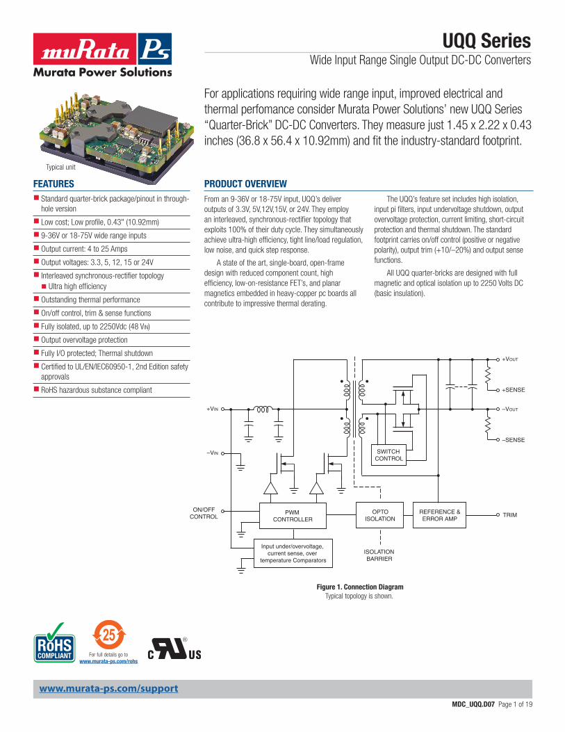
From an 9-36V or 18-75V input, UQQ’s deliver outputs of 3.3V, 5V,12V,15V, or 24V. They employ an interleaved, synchronous-rectifier topology that exploits 100% of their duty cycle. They simultaneously achieve ultra-high efficiency, tight line/load regulation, low noise, and quick step response.
A state of the art, single-board, open-frame design with reduced component count, high efficiency, low-on-resistance FET’s, and planar magnetics embedded in heavy-copper pc boards all contribute to impressive thermal derating.
The UQQ’s feature set includes high isolation, input pi filters, input undervoltage shutdown, output overvoltage protection, current limiting, short-circuit protection and thermal shutdown. The standard footprint carries on/off control (positive or negative polarity), output trim (+10/–20%) and output sense functions.
All UQQ quarter-bricks are designed with full magnetic and optical isolation up to 2250 Volts DC (basic insulation).
For applications requiring wide range input, improved electrical and thermal perfomance consider Murata Power Solutions’ new UQQ Series “Quarter-Brick” DC-DC Converters. They measure just 1.45 x 2.22 x 0.43 inches (36.8 x 56.4 x 10.92mm) and fit the industry-standard footprint.
PRODUCT OVERVIEW
Typical unit
SWITCH CONTROL
OPTOISOLATION
ISOLATIONBARRIER
PWM CONTROLLER
REFERENCE &ERROR AMP
Input under/overvoltage, current sense, over
temperature Comparators
+VIN
+VOUT
–VOUT
–VIN
ON/OFFCONTROL TRIM
–SENSE
+SENSE
Typical topology is shown.Figure 1. Connection Diagram
www.murata-ps.com/support
UQQ SeriesWide Input Range Single Output DC-DC Converters
MDC_UQQ.D07 Page 2 of 19
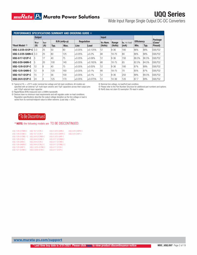
PERFORMANCE SPECIFICATIONS SUMMARY AND ORDERING GUIDE
*Root Model
Output Input
EfficiencyPackage (Case/ Pinout)
VOUT (V)
IOUT
(A)
R/N (mVp-p) Regulation VIN Nom. (Volts)
Range (Volts)
IIN, no load (mA)Typ. Max. Line Load Min. Typ.
UQQ-3.3/25-Q12P-C 3.3 25 50 80 ±0.05% ±0.125% 12 9-36 180 86% 88% C68,P32
UQQ-3.3/25-Q48N-C 3.3 25 80 125 ±0.05% ±0.2% 48 18-75 80 86% 88% C68,P32
UQQ-5/17-Q12P-C 5 17 40 75 ±0.05% ±0.06% 12 9-36 150 88.5% 90.5% C68,P32
UQQ-5/20-Q48N-C 5 20 100 140 ±0.05% ±0.165% 48 18-75 65 82.5% 84.5% C68,P32
UQQ-12/8-Q12P-C 12 8 40 75 ±0.05% ±0.05% 12 9-36 180 87% 89% C68,P32
UQQ-12/8-Q48N-C 12 8 120 160 ±0.05% ±0.1% 48 18-75 70 85% 87% C68,P32
UQQ-15/7-Q12P-C 15 7 56 100 ±0.05% ±0.1% 12 9-36 250 88% 89.5% C68,P32
UQQ-24/4-Q12P-C 24 4 125 170 ±0.05% ±0.075% 12 10-36 120 87.7 89% C68,P32
Typical at TA = +25°C under nominal line voltage and full-load conditions. All models are specified with an external 1μF multi-layer ceramic and 10μF capacitors across their output pins and 100μF external input capacitor.
Ripple/Noise (R/N) measured over a 20MHz bandwidth. Devices have no minimum-load requirements and will regulate under no-load conditions.
Regulation specifications describe the output voltage deviation as the line voltage or load is varied from its nominal/midpoint value to either extreme. (Load step = 50%.)
Nominal line voltage, no load/full load condition. Please refer to the Part Number Structure for additional part numbers and options. RoHS does not claim EU exemption 7B–lead in solder.
* Last time buy date is 3/31/2021. Please click here to view product discontinuance notice
* To Be Discontinued
UQQ-12/8-Q12NB9-C UQQ-15/7-Q12N-C UQQ-3.3/25-Q48N-C UQQ-5/20-Q48PB-C
UQQ-12/8-Q12NB-C UQQ-15/7-Q12N-Y UQQ-3.3/25-Q48PB-C UQQ-5/20-Q48P-CUQQ-12/8-Q12NBL1-C UQQ-24/4-Q12NB9-C UQQ-3.3/25-Q48P-CUQQ-12/8-Q12N-C UQQ-24/4-Q12NB-C UQQ-5/17-Q12NB9-CUQQ-12/8-Q48N-C UQQ-24/4-Q12N-C UQQ-5/17-Q12NB-CUQQ-12/8-Q48PB-C UQQ-24/4-Q12NL2-C UQQ-5/17-Q12NBL2-CUQQ-12/8-Q48P-C UQQ-3.3/25-Q12NB-C UQQ-5/17-Q12N-CUQQ-15/7-Q12NB-C UQQ-3.3/25-Q12N-C UQQ-5/17-Q12P-C
* NOTE: the following models are TO BE DISCONTINUED:
www.murata-ps.com/support
UQQ SeriesWide Input Range Single Output DC-DC Converters
MDC_UQQ.D07 Page 3 of 19
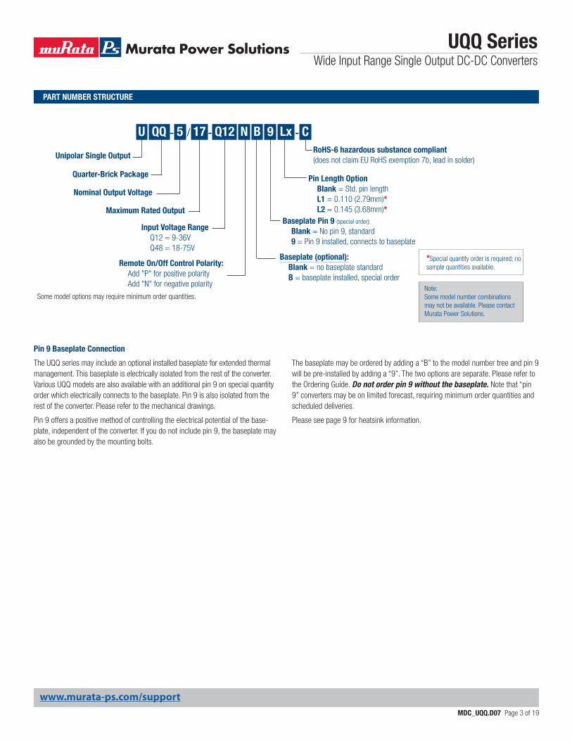
Maximum Rated Output
Quarter-Brick Package
Unipolar Single Output
Nominal Output Voltage
U QQ - / Q12-5 17 N Lx
Input Voltage Range Q12 = 9-36V Q48 = 18-75V
Remote On/Off Control Polarity: Add "P" for positive polarity Add "N" for negative polarity
Pin Length Option Blank = Std. pin length L1 = 0.110 (2.79mm)* L2 = 0.145 (3.68mm)*
CRoHS-6 hazardous substance compliant(does not claim EU RoHS exemption 7b, lead in solder)
-9
Baseplate (optional): Blank = no baseplate standard B = baseplate installed, special order
Baseplate Pin 9 (special order):
Blank = No pin 9, standard 9 = Pin 9 installed, connects to baseplate
Some model options may require minimum order quantities.
B
Pin 9 Baseplate Connection
The UQQ series may include an optional installed baseplate for extended thermal management. This baseplate is electrically isolated from the rest of the converter. Various UQQ models are also available with an additional pin 9 on special quantity order which electrically connects to the baseplate. Pin 9 is also isolated from the rest of the converter. Please refer to the mechanical drawings.
Pin 9 offers a positive method of controlling the electrical potential of the base-plate, independent of the converter. If you do not include pin 9, the baseplate may also be grounded by the mounting bolts.
The baseplate may be ordered by adding a “B” to the model number tree and pin 9 will be pre-installed by adding a “9”. The two options are separate. Please refer to the Ordering Guide. Do not order pin 9 without the baseplate. Note that “pin 9” converters may be on limited forecast, requiring minimum order quantities and scheduled deliveries.
Please see page 9 for heatsink information.
PART NUMBER STRUCTURE
Note:Some model number combinations may not be available. Please contact Murata Power Solutions.
*Special quantity order is required; no sample quantities available.
www.murata-ps.com/support
UQQ SeriesWide Input Range Single Output DC-DC Converters
MDC_UQQ.D07 Page 4 of 19
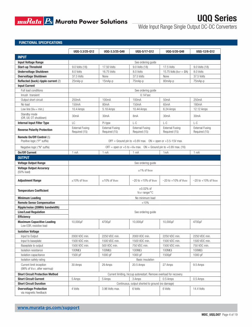
UQQ-3.3/25-Q12 UQQ-3.3/25-Q48 UQQ-5/17-Q12 UQQ-5/20-Q48 UQQ-12/8-Q12
INPUTInput Voltage Range See ordering guide
Start-up Threshold 9.0 Volts (18) 17.50 Volts 9.0 Volts (18) 17.5 Volts 9.0 Volts (18)
Undervoltage Shutdown 8.0 Volts 16.75 Volts 8.0 Volts 15.75 Volts (Iout = ØA) 8.0 Volts
Overvoltage Shutdown 37.5 Volts None 37.5 Volts None 37.5 Volts
Reflected (back) ripple current (2) 25mAp-p 15mAp-p 75mAp-p 80mAp-p 75mAp-p
Input Current Full load conditions See ordering guide
Inrush transient 0.1A2sec
Output short circuit 250mA 100mA 100mA 50mA 250mA
No load 150mA 80mA 150mA 65mA 180mA
Low line (VIN = min.) 10.4 Amps 5.18 Amps 10.44 Amps 6.24 Amps 12.12 Amps
Standby mode (Off, UV, OT shutdown) 30mA 30mA 8mA 30mA 30mA
Internal Input Filter Type LC Pi-type L-C L-C L-C
Reverse Polarity ProtectionExternal Fusing Required (15)
External Fusing Required (15)
External Fusing Required (15)
External Fusing Required (15)
External Fusing Required (15)
Remote On/Off Control (5) Positive logic (“P” suffix)
OFF = Ground pin to +0.8V max. ON = open or +3.5-15V max.
Negative logic (“N” suffix) OFF = open or +5 to +VIN max. ON = Ground pin to +0.8V max. (16)
On/Off Current 1 mA 1 mA 1 mA 1mA 1 mA
OUTPUTVoltage Output Range See ordering guide
Voltage Output Accuracy (50% load) ±1% of VNOM
Adjustment Range ±10% of VNOM ±10% of VNOM –20 to +10% of VNOM –20 to +10% of VNOM –20 to +10% of VNOM
Temperature Coefficient±0.02% of
VOUT range/°C
Minimum Loading No minimum load
Remote Sense Compensation +10%
Ripple/noise (20MHz bandwidth)See ordering guideLine/Load Regulation
Efficiency
Maximum Capacitive Loading Low ESR, resistive load
10,000μF 4700μF 10,000μF 10,000μF 4700μF
Isolation Voltage Input to Output 2000 VDC min. 2250 VDC min. 2000 VDC min. 2250 VDC min. 2250 VDC min.
Input fo baseplate 1500 VDC min. 1500 VDC min. 1500 VDC min. 1500 VDC min. 1500 VDC min.
Baseplate to output 1500 VDC min. 500 VDC min. 750 VDC min. 1500 VDC min. 750 VDC min.
Isolation resistance 100MW 100MW 100MW 100MW 100MW Isolation capacitance 1500 pF 1000 pF 1000 pF 1500pF 1000 pF
Isolation safety rating Basic insulation
Current limit inception (98% of Vout, after warmup)
30 Amps 29 Amps 20.5 Amps 27 Amps 9.5 Amps
Short Circuit Protection Method Current limiting, hiccup autorestart. Remove overload for recovery.
Short Circuit Current 5 Amps 5 Amps 3 Amps 0.5 Amps 0.5 Amps
Short Circuit Duration Continuous, output shorted to ground (no damage)
Overvoltage Protection via magnetic feedback
4 Volts 3.96 Volts max. 6 Volts 6 Volts 14.4 Volts
FUNCTIONAL SPECIFICATIONS
www.murata-ps.com/support
UQQ SeriesWide Input Range Single Output DC-DC Converters
MDC_UQQ.D07 Page 5 of 19
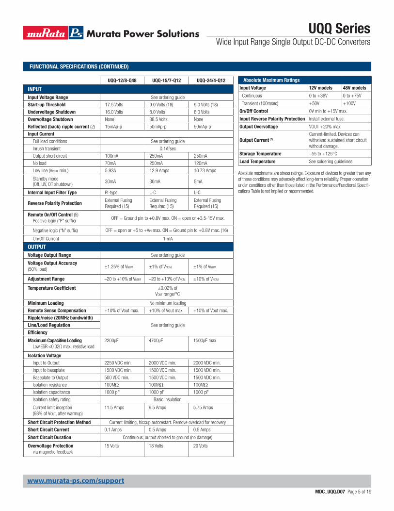
UQQ-12/8-Q48 UQQ-15/7-Q12 UQQ-24/4-Q12
INPUTInput Voltage Range See ordering guide
Start-up Threshold 17.5 Volts 9.0 Volts (18) 9.0 Volts (18)
Undervoltage Shutdown 16.0 Volts 8.0 Volts 8.0 Volts
Overvoltage Shutdown None 38.5 Volts None
Reflected (back) ripple current (2) 15mAp-p 50mAp-p 50mAp-p
Input Current Full load conditions See ordering guide
Inrush transient 0.1A2sec
Output short circuit 100mA 250mA 250mA
No load 70mA 250mA 120mA
Low line (VIN = min.) 5.93A 12.9 Amps 10.73 Amps
Standby mode (Off, UV, OT shutdown) 30mA 30mA 5mA
Internal Input Filter Type PI-type L-C L-C
Reverse Polarity ProtectionExternal Fusing Required (15)
External Fusing Required (15)
External Fusing Required (15)
Remote On/Off Control (5) Positive logic (“P” suffix) OFF = Ground pin to +0.8V max. ON = open or +3.5-15V max.
Negative logic (“N” suffix) OFF = open or +5 to +VIN max. ON = Ground pin to +0.8V max. (16)
On/Off Current 1 mA
OUTPUTVoltage Output Range See ordering guide
Voltage Output Accuracy (50% load) ±1.25% of VNOM ±1% of VNOM ±1% of VNOM
Adjustment Range –20 to +10% of VNOM –20 to +10% of VNOM ±10% of VNOM
Temperature Coefficient ±0.02% of VOUT range/°C
Minimum Loading No minimum loading
Remote Sense Compensation +10% of Vout max. +10% of Vout max. +10% of Vout max.
Ripple/noise (20MHz bandwidth)See ordering guideLine/Load Regulation
Efficiency
Maximum Capacitive Loading Low ESR <0.02Ω max., resistive load
2200µF 4700μF 1500μF max
Isolation Voltage Input to Output 2250 VDC min. 2000 VDC min. 2000 VDC min.
Input fo baseplate 1500 VDC min. 1500 VDC min. 1500 VDC min.
Baseplate to Output 500 VDC min. 1500 VDC min. 1500 VDC min.
Isolation resistance 100MW 100MW 100MW Isolation capacitance 1000 pF 1000 pF 1000 pF
Isolation safety rating Basic insulation
Current limit inception (98% of Vout, after warmup)
11.5 Amps 9.5 Amps 5.75 Amps
Short Circuit Protection Method Current limiting, hiccup autorestart. Remove overload for recovery
Short Circuit Current 0.1 Amps 0.5 Amps 0.5 Amps
Short Circuit Duration Continuous, output shorted to ground (no damage)
Overvoltage Protection via magnetic feedback
15 Volts 18 Volts 29 Volts
Absolute Maximum Ratings
Input Voltage 12V models 48V models
Continuous 0 to +36V 0 to +75V
Transient (100msec) +50V +100V
On/Off Control 0V min to +15V max.
Input Reverse Polarity Protection Install external fuse.
Output Overvoltage VOUT +20% max.
Output Current (7)Current-limited. Devices can withstand sustained short circuit without damage.
Storage Temperature –55 to +125°C
Lead Temperature See soldering guidelines
Absolute maximums are stress ratings. Exposure of devices to greater than any of these conditions may adversely affect long-term reliability. Proper operation under conditions other than those listed in the Performance/Functional Specifi-cations Table is not implied or recommended.
FUNCTIONAL SPECIFICATIONS (CONTINUED)
www.murata-ps.com/support
UQQ SeriesWide Input Range Single Output DC-DC Converters
MDC_UQQ.D07 Page 6 of 19
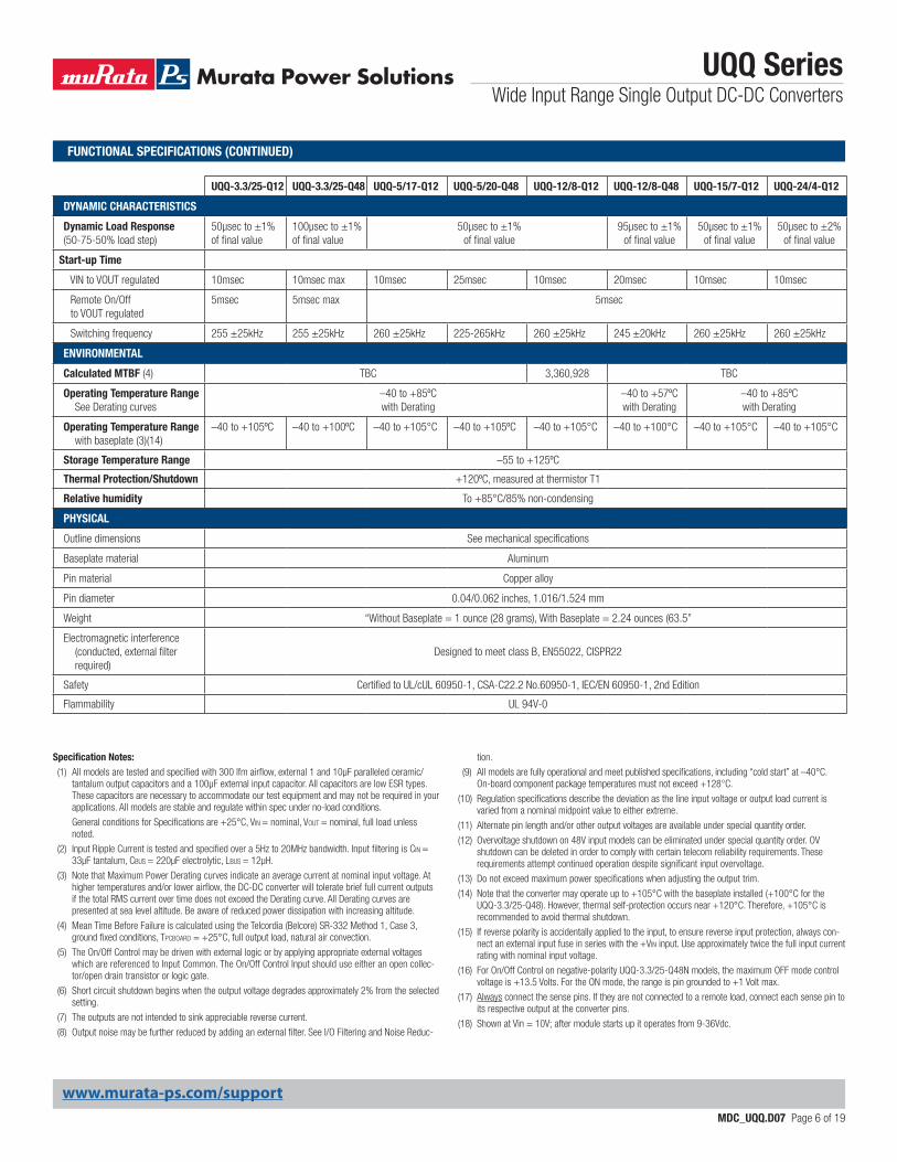
UQQ-3.3/25-Q12 UQQ-3.3/25-Q48 UQQ-5/17-Q12 UQQ-5/20-Q48 UQQ-12/8-Q12 UQQ-12/8-Q48 UQQ-15/7-Q12 UQQ-24/4-Q12
DYNAMIC CHARACTERISTICS
Dynamic Load Response (50-75-50% load step)
50μsec to ±1% of final value
100μsec to ±1% of final value
50μsec to ±1% of final value
95μsec to ±1% of final value
50μsec to ±1% of final value
50μsec to ±2% of final value
Start-up Time
VIN to VOUT regulated 10msec 10msec max 10msec 25msec 10msec 20msec 10msec 10msec
Remote On/Off to VOUT regulated
5msec 5msec max 5msec
Switching frequency 255 ±25kHz 255 ±25kHz 260 ±25kHz 225-265kHz 260 ±25kHz 245 ±20kHz 260 ±25kHz 260 ±25kHz
ENVIRONMENTAL
Calculated MTBF (4) TBC 3,360,928 TBC
Operating Temperature Range See Derating curves
–40 to +85ºC with Derating
–40 to +57ºC with Derating
–40 to +85ºC with Derating
Operating Temperature Range with baseplate (3)(14)
–40 to +105ºC –40 to +100ºC –40 to +105°C –40 to +105ºC –40 to +105°C –40 to +100°C –40 to +105°C –40 to +105°C
Storage Temperature Range –55 to +125ºC
Thermal Protection/Shutdown +120ºC, measured at thermistor T1
Relative humidity To +85°C/85% non-condensing
PHYSICAL
Outline dimensions See mechanical specifications
Baseplate material Aluminum
Pin material Copper alloy
Pin diameter 0.04/0.062 inches, 1.016/1.524 mm
Weight “Without Baseplate = 1 ounce (28 grams), With Baseplate = 2.24 ounces (63.5”
Electromagnetic interference (conducted, external filter required)
Designed to meet class B, EN55022, CISPR22
Safety Certified to UL/cUL 60950-1, CSA-C22.2 No.60950-1, IEC/EN 60950-1, 2nd Edition
Flammability UL 94V-0
Specification Notes:(1) All models are tested and specified with 300 lfm airflow, external 1 and 10µF paralleled ceramic/
tantalum output capacitors and a 100µF external input capacitor. All capacitors are low ESR types. These capacitors are necessary to accommodate our test equipment and may not be required in your applications. All models are stable and regulate within spec under no-load conditions.
General conditions for Specifications are +25°C, VIN = nominal, VOUT = nominal, full load unless noted.
(2) Input Ripple Current is tested and specified over a 5Hz to 20MHz bandwidth. Input filtering is CIN = 33µF tantalum, CBUS = 220µF electrolytic, LBUS = 12µH.
(3) Note that Maximum Power Derating curves indicate an average current at nominal input voltage. At higher temperatures and/or lower airflow, the DC-DC converter will tolerate brief full current outputs if the total RMS current over time does not exceed the Derating curve. All Derating curves are presented at sea level altitude. Be aware of reduced power dissipation with increasing altitude.
(4) Mean Time Before Failure is calculated using the Telcordia (Belcore) SR-332 Method 1, Case 3, ground fixed conditions, Tpcboard = +25°C, full output load, natural air convection.
(5) The On/Off Control may be driven with external logic or by applying appropriate external voltages which are referenced to Input Common. The On/Off Control Input should use either an open collec-tor/open drain transistor or logic gate.
(6) Short circuit shutdown begins when the output voltage degrades approximately 2% from the selected setting.
(7) The outputs are not intended to sink appreciable reverse current.
(8) Output noise may be further reduced by adding an external filter. See I/O Filtering and Noise Reduc-
tion.
(9) All models are fully operational and meet published specifications, including “cold start” at –40°C. On-board component package temperatures must not exceed +128°C.
(10) Regulation specifications describe the deviation as the line input voltage or output load current is varied from a nominal midpoint value to either extreme.
(11) Alternate pin length and/or other output voltages are available under special quantity order.
(12) Overvoltage shutdown on 48V input models can be eliminated under special quantity order. OV shutdown can be deleted in order to comply with certain telecom reliability requirements. These requirements attempt continued operation despite significant input overvoltage.
(13) Do not exceed maximum power specifications when adjusting the output trim.
(14) Note that the converter may operate up to +105°C with the baseplate installed (+100°C for the UQQ-3.3/25-Q48). However, thermal self-protection occurs near +120°C. Therefore, +105°C is recommended to avoid thermal shutdown.
(15) If reverse polarity is accidentally applied to the input, to ensure reverse input protection, always con-nect an external input fuse in series with the +VIN input. Use approximately twice the full input current rating with nominal input voltage.
(16) For On/Off Control on negative-polarity UQQ-3.3/25-Q48N models, the maximum OFF mode control voltage is +13.5 Volts. For the ON mode, the range is pin grounded to +1 Volt max.
(17) Always connect the sense pins. If they are not connected to a remote load, connect each sense pin to its respective output at the converter pins.
(18) Shown at Vin = 10V; after module starts up it operates from 9-36Vdc.
FUNCTIONAL SPECIFICATIONS (CONTINUED)
www.murata-ps.com/support
TYPICAL PERFORMANCE DATA
UQQ SeriesWide Input Range Single Output DC-DC Converters
MDC_UQQ.D07 Page 7 of 19
64
66
68
70
72
74
76
78
80
82
84
86
88
90
2 4 6 8 10 12 14 16 18 20 22 24 26
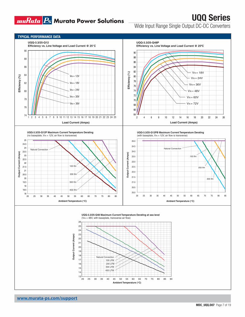
UQQ-3.3/25-Q48PEfficiency vs. Line Voltage and Load Current @ 25ºC
Load Current (Amps)
Eff
icie
ncy
(%
)
VIN = 72V
VIN = 60V
VIN = 48V
VIN = 36V
VIN = 24V
VIN = 18V
18
18.5
19
19.5
20
20.5
21
21.5
22
22.5
23
23.5
24
24.5
25
20 25 30 35 40 45 50 55 60 65 70 75 80 85
UQQ-3.3/25-Q12P Maximum Current Temperature Derating(no baseplate, VIN = 12V, air flow is transverse)
Natural Convection
300 lfm
Ou
tpu
t C
urr
ent
(Am
ps)
Ambient Temperature (°C)
400 lfm
200 lfm
100 lfm
13
14
15
16
17
18
19
20
21
22
23
24
25
26
20 25 30 35 40 45 50 55 60 65 70 75 80 85 90
Natural Convection
300 LFM
400 LFM
200 LFM
100 LFM
UQQ-3.3/25-Q48 Maximum Current Temperature Derating at sea level(VIN = 48V, with baseplate, transverse air flow)
Ou
tpu
t C
urr
ent
(Am
ps)
Ambient Temperature (°C)
20.0
20.5
21.0
21.5
22.0
22.5
23.0
23.5
24.0
24.5
25.0
20 25 30 35 40 45 50 55 60 65 70 75 80 85
Ou
tpu
t C
urr
ent
(Am
ps)
Ambient Temperature (°C)
UQQ-3.3/25-Q12PB Maximum Current Temperature Derating(with baseplate, VIN = 12V, air flow is transverse)
200 lfm
300 lfm
100 lfm
Natural Convection
UQQ-3.3/25-Q12Efficiency vs. Line Voltage and Load Current @ 25°C
Load Current (Amps)
Eff
icie
ncy
(%
)
VIN = 36V
VIN = 30V
VIN = 24V
90
88
86
84
82
80
78
76
741 2 3 4 5 6 7 8 9 10 11 12 13 14 15 16 17 18 19 20 21 22 23 24 25
VIN = 18V
VIN = 12V
www.murata-ps.com/support
TYPICAL PERFORMANCE DATA
UQQ SeriesWide Input Range Single Output DC-DC Converters
MDC_UQQ.D07 Page 8 of 19
94
92
90
88
86
84
82
80
78
76
74
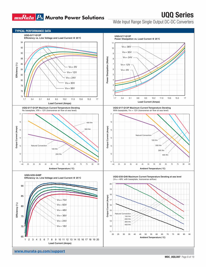
UQQ-5/17-Q12PEfficiency vs. Line Voltage and Load Current @ 25°C
Load Current (Amps)
Eff
icie
ncy
(%
)
1.7 3.4 5.1 6.8 8.5 10.2 11.9 13.6 15.3 17
VIN = 36V
VIN = 30V
VIN = 24V
VIN = 12V
VIN = 9V
65
70
75
80
85
90
1 2 3 4 5 6 7 8 9 10 11 12 13 14 15 16 17 18 19 20
VIN = 18V
VIN = 24V
VIN = 36V
VIN = 48V
VIN = 60V
VIN = 75V
UQQ-5/20-Q48PEfficiency vs. Line Voltage and Load Current @ 25°C
Load Current (Amps)
Eff
icie
ncy
(%
)
11
10
9
8
7
6
5
4
3
2
1
UQQ-5/17-Q12PPower Dissipation vs. Load Current @ 25°C
1.7 3.4 5.1 6.8 8.5 10.2 11.9 13.6 15.3 17
Load Current (Amps)
Po
wer
Dis
sip
atio
n (
Wat
ts)
VIN = 36V
VIN = 30V
VIN = 24V
VIN = 12V
VIN = 9V
Ou
tpu
t C
urr
ent
(Am
ps)
Ambient Temperature (°C)
–40 25 30 35 40 45 50 55 60 65 70 75 80 85
17
16
15
14
13
12
11
400 lfm
200 lfm
300 lfm
100 lfm
Natural Convection
UQQ-5/17-Q12P Maximum Current Temperature DeratingWith baseplate, VIN = 12V (transverse air flow at sea level)
11
12
13
14
15
16
17
18
19
20
20 25 30 35 40 45 50 55 60 65 70 75 80 85 90
400 lfm
200 lfm
300 lfm
100 lfmNatural Convection
UQQ-5/20-Q48 Maximum Current Temperature Derating at sea level(VIN = 48V, with baseplate, transverse airflow)
Ou
tpu
t C
urr
ent
(Am
ps)
Ambient Temperature (°C)
Ou
tpu
t C
urr
ent
(Am
ps)
Ambient Temperature (°C)
–40 25 30 35 40 45 50 55 60 65 70 75 80 85
17
16
15
14
13
12
11
400 lfm
200 lfm
300 lfm
100 lfm
Natural Convection
UQQ-5/17-Q12P Maximum Current Temperature DeratingNo baseplate, VIN = 12V (transverse air flow at sea level)
www.murata-ps.com/support
TYPICAL PERFORMANCE DATA
UQQ SeriesWide Input Range Single Output DC-DC Converters
MDC_UQQ.D07 Page 9 of 19
12
11
10
9
8
7
6
5
4
3
2
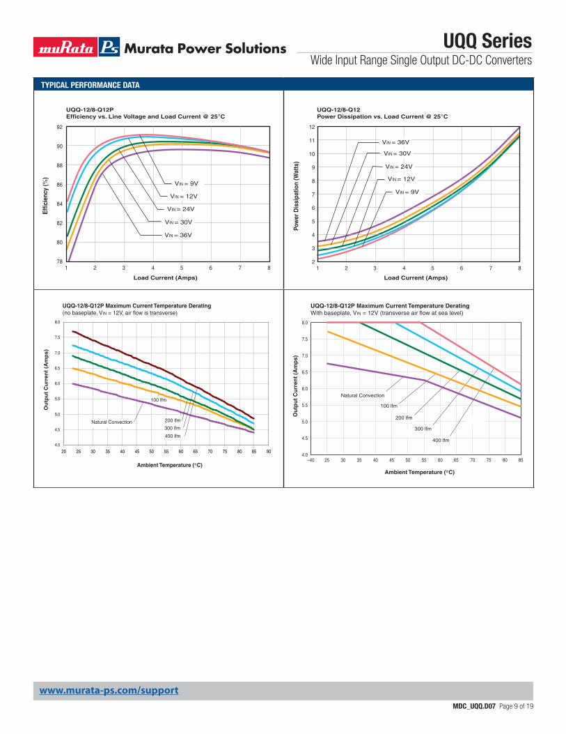
UQQ-12/8-Q12Power Dissipation vs. Load Current @ 25°C
1 2 3 4 5 6 7 8
Load Current (Amps)
Pow
er D
issi
patio
n (W
atts
)
VIN = 36V
VIN = 30V
VIN = 24V
VIN = 12V
VIN = 9V
Ou
tpu
t C
urr
ent
(Am
ps)
Ambient Temperature (°C)
–40 25 30 35 40 45 50 55 60 65 70 75 80 85
8.0
7.5
7.0
6.5
6.0
5.5
5.0
4.5
4.0
400 lfm
200 lfm
300 lfm
100 lfm
Natural Convection
UQQ-12/8-Q12P Maximum Current Temperature DeratingWith baseplate, VIN = 12V (transverse air flow at sea level)
4.0
4.5
5.0
5.5
6.0
6.5
7.0
7.5
8.0
20 25 30 35 40 45 50 55 60 65 70 75 80 85 90
UQQ-12/8-Q12P Maximum Current Temperature Derating(no baseplate, VIN = 12V, air flow is transverse)
Ou
tpu
t C
urr
ent
(Am
ps)
Ambient Temperature (°C)
Natural Convection
100 lfm
200 lfm
300 lfm
400 lfm
92
90
88
86
84
82
80
78
UQQ-12/8-Q12PEfficiency vs. Line Voltage and Load Current @ 25°C
Load Current (Amps)
Effic
ienc
y (%
)
1 2 3 4 5 6 7 8
VIN = 36V
VIN = 30V
VIN = 24V
VIN = 12V
VIN = 9V
www.murata-ps.com/support
TYPICAL PERFORMANCE DATA
UQQ SeriesWide Input Range Single Output DC-DC Converters
MDC_UQQ.D07 Page 10 of 19
74
76
78
80
82
84
86
88
90
92
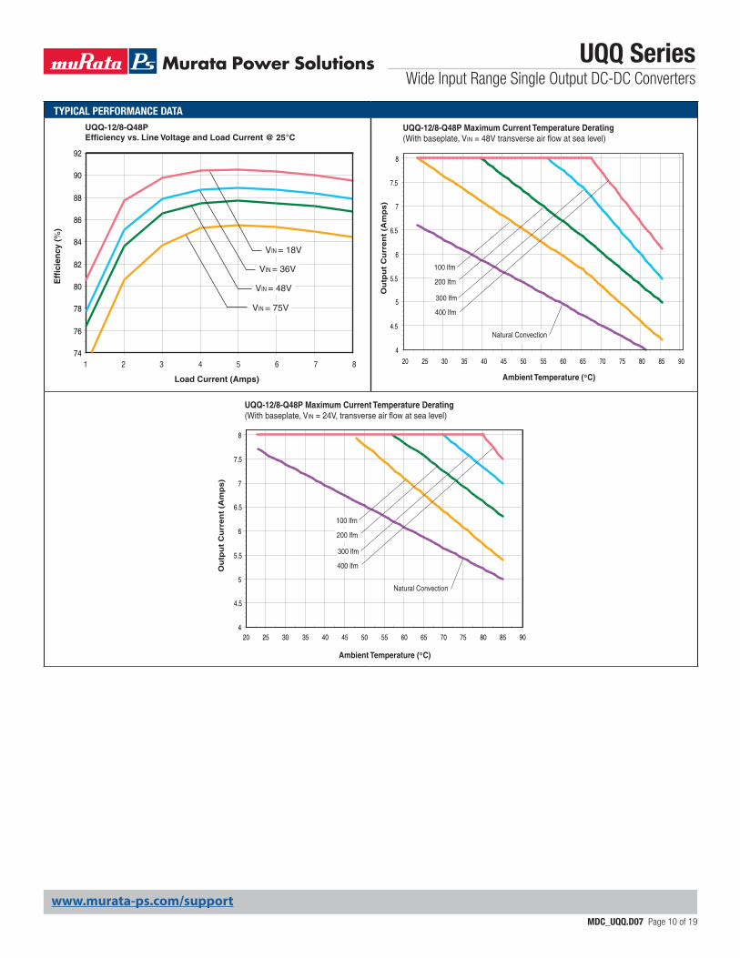
UQQ-12/8-Q48PEfficiency vs. Line Voltage and Load Current @ 25°C
Load Current (Amps)
Eff
icie
ncy
(%
)
1 2 3 4 5 6 7 8
VIN = 75V
VIN = 48V
VIN = 36V
VIN = 18V
4
4.5
5
5.5
6
6.5
7
7.5
8
20 25 30 35 40 45 50 55 60 65 70 75 80 85 90
Ou
tpu
t C
urr
en
t (A
mp
s)
Ambient Temperature (°C)
UQQ-12/8-Q48P Maximum Current Temperature Derating(With baseplate, VIN = 48V transverse air flow at sea level)
Natural Convection
100 lfm
200 lfm
300 lfm
400 lfm
4
4.5
5
5.5
6
6.5
7
7.5
8
20 25 30 35 40 45 50 55 60 65 70 75 80 85 90
Ou
tpu
t C
urr
en
t (A
mp
s)
Ambient Temperature (°C)
UQQ-12/8-Q48P Maximum Current Temperature Derating(With baseplate, VIN = 24V, transverse air flow at sea level)
Natural Convection
100 lfm
200 lfm
300 lfm
400 lfm
www.murata-ps.com/support
TYPICAL PERFORMANCE DATA
UQQ SeriesWide Input Range Single Output DC-DC Converters
MDC_UQQ.D07 Page 11 of 19
12
11
10
9
8
7
6
5
4
3
2
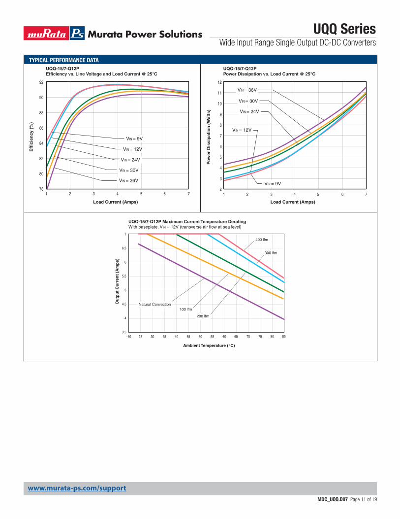
UQQ-15/7-Q12PPower Dissipation vs. Load Current @ 25°C
1 2 3 4 5 6 7
Load Current (Amps)
Po
wer
Dis
sip
atio
n (
Wat
ts)
VIN = 36V
VIN = 30V
VIN = 24V
VIN = 12V
VIN = 9V
92
90
88
86
84
82
80
78
UQQ-15/7-Q12PEfficiency vs. Line Voltage and Load Current @ 25°C
Load Current (Amps)
Eff
icie
ncy
(%
)
1 2 3 4 5 6 7
VIN = 36V
VIN = 30V
VIN = 24V
VIN = 12V
VIN = 9V
Ou
tpu
t C
urr
ent
(Am
ps)
Ambient Temperature (°C)
–40 25 30 35 40 45 50 55 60 65 70 75 80 85
7
6.5
6
5.5
5
4.5
4
3.5
200 lfm
300 lfm
100 lfm Natural Convection
400 lfm
UQQ-15/7-Q12P Maximum Current Temperature DeratingWith baseplate, VIN = 12V (transverse air flow at sea level)
www.murata-ps.com/support
TYPICAL PERFORMANCE DATA
UQQ SeriesWide Input Range Single Output DC-DC Converters
MDC_UQQ.D07 Page 12 of 19
Ou
tpu
t C
urr
ent
(Am
ps)
Ambient Temperature (°C)
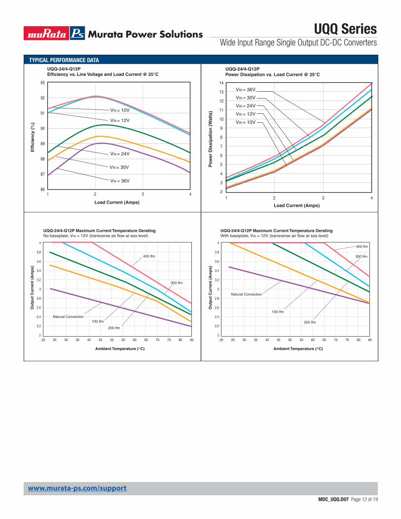
20 25 30 35 40 45 50 55 60 65 70 75 8580
4
3.8
3.6
3.4
3.2
3
2.8
2.6
2.4
2.2
2
200 lfm
300 lfm
100 lfmNatural Convection
400 lfm
UQQ-24/4-Q12P Maximum Current Temperature DeratingNo baseplate, VIN = 12V (transverse air flow at sea level)
Ou
tpu
t C
urr
ent
(Am
ps)
Ambient Temperature (°C)
20 25 30 35 40 45 50 55 60 65 70 75 8580
4
3.8
3.6
3.4
3.2
3
2.8
2.6
2.4
2.2
2
200 lfm
300 lfm
100 lfm
Natural Convection
400 lfm
UQQ-24/4-Q12P Maximum Current Temperature DeratingWith baseplate, VIN = 12V (transverse air flow at sea level)
93
92
91
90
89
88
87
86
UQQ-24/4-Q12PEfficiency vs. Line Voltage and Load Current @ 25°C
Load Current (Amps)
Eff
icie
ncy
(%
)
1 2 3 4
VIN = 36V
VIN = 30V
VIN = 24V
VIN = 12V
VIN = 10V
UQQ-24/4-Q12PPower Dissipation vs. Load Current @ 25°C
1
Load Current (Amps) P
ow
er D
issi
pat
ion
(W
atts
)
42 32
3
4
5
6
7
8
9
10
11
12
13
14
VIN = 36V
VIN = 30V
VIN = 24V
VIN = 12V
VIN = 10V
www.murata-ps.com/support
UQQ SeriesWide Input Range Single Output DC-DC Converters
MDC_UQQ.D07 Page 13 of 19
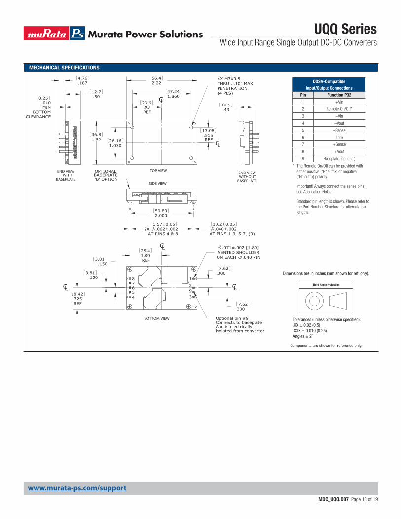
MECHANICAL SPECIFICATIONS
* The Remote On/Off can be provided with either positive ("P" suffix) or negative ("N" suffix) polarity.
Important! Always connect the sense pins; see Application Notes.
Standard pin length is shown. Please refer to the Part Number Structure for alternate pin lengths.
.4310.9
REF
25.41.00
7.62.300
7.62.300
3.81.150
3.81.150
.725REF
18.42
2.00050.80
.93REF
23.6
.515REF
13.08
END VIEWWITHOUT
BASEPLATE
CL
CL
CL
87654
1
29
Connects to baseplateAnd is electricallyisolated from converter
3
Optional pin #9BOTTOM VIEW
.071±.002 [1.80]VENTED SHOULDERON EACH .040 PIN
OPTIONAL BASEPLATE'B' OPTION
SIDE VIEW
AT PINS 1-3, 5-7, (9)
1.02±0.05.040±.0022X .062±.002
AT PINS 4 & 8
1.57±0.05
END VIEWWITH
BASEPLATE
12.7.50
4.76.187
.010MIN
BOTTOMCLEARANCE
0.25
CL
CL
TOP VIEW
2.2256.4
1.86047.24
1.03026.16
THRU , .10" MAXPENETRATION (4 PLS)
4X M3X0.5
1.4536.8
DOSA-Compatible Input/Output Connections
Pin Function P32
1 +Vin
2 Remote On/Off*
3 –Vin
4 –Vout
5 –Sense
6 Trim
7 +Sense
8 +Vout
9 Baseplate (optional)
Third Angle Projection
Dimensions are in inches (mm shown for ref. only).
Components are shown for reference only.
Tolerances (unless otherwise specified):.XX ± 0.02 (0.5).XXX ± 0.010 (0.25)Angles ± 2˚
www.murata-ps.com/support
UQQ SeriesWide Input Range Single Output DC-DC Converters
MDC_UQQ.D07 Page 14 of 19
Removal of Soldered UQQ’s from Printed Circuit Boards
Should removal of the UQQ from its soldered connection be needed, thoroughly de-solder the pins using solder wicks or de-soldering tools. At no time should any prying or leverage be used to remove boards that have not been properly de-soldered first.
Input Source Impedance
UQQ converters must be driven from a low ac-impedance input source. The DC-DC’s performance and stability can be compromised by the use of highly inductive source impedances. The input circuit shown in Figure 2 is a practical solution that can be used to minimize the effects of inductance in the input traces. For optimum performance, components should be mounted close to the DC-DC converter.
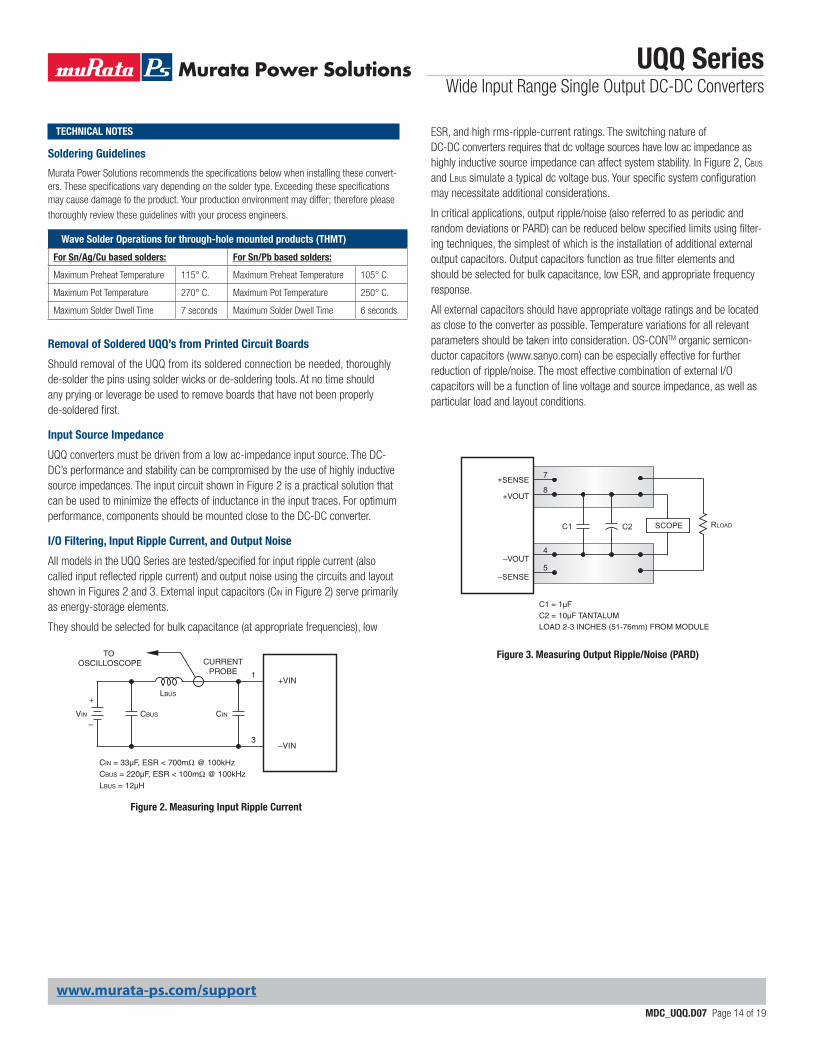
I/O Filtering, Input Ripple Current, and Output Noise
All models in the UQQ Series are tested/specified for input ripple current (also called input reflected ripple current) and output noise using the circuits and layout shown in Figures 2 and 3. External input capacitors (CIN in Figure 2) serve primarily as energy-storage elements.
They should be selected for bulk capacitance (at appropriate frequencies), low
Figure 2. Measuring Input Ripple Current
CINVIN CBUS
LBUS
CIN = 33µF, ESR < 700mΩ @ 100kHzCBUS = 220µF, ESR < 100mΩ @ 100kHzLBUS = 12µH
1
3
+VIN
–VIN
CURRENTPROBE
TO OSCILLOSCOPE
+
–
TECHNICAL NOTES ESR, and high rms-ripple-current ratings. The switching nature of DC-DC converters requires that dc voltage sources have low ac impedance as highly inductive source impedance can affect system stability. In Figure 2, CBUS and LBUS simulate a typical dc voltage bus. Your specific system configuration may necessitate additional considerations.
In critical applications, output ripple/noise (also referred to as periodic and random deviations or PARD) can be reduced below specified limits using filter-ing techniques, the simplest of which is the installation of additional external output capacitors. Output capacitors function as true filter elements and should be selected for bulk capacitance, low ESR, and appropriate frequency response.
All external capacitors should have appropriate voltage ratings and be located as close to the converter as possible. Temperature variations for all relevant parameters should be taken into consideration. OS-CONTM organic semicon-ductor capacitors (www.sanyo.com) can be especially effective for further reduction of ripple/noise. The most effective combination of external I/O capacitors will be a function of line voltage and source impedance, as well as particular load and layout conditions.
Figure 3. Measuring Output Ripple/Noise (PARD)
C1
C1 = 1µF C2 = 10µF TANTALUMLOAD 2-3 INCHES (51-76mm) FROM MODULE
C2 RLOAD
7
8
4
5
SCOPE
+VOUT
–VOUT
+SENSE
–SENSE
Soldering Guidelines
Murata Power Solutions recommends the specifications below when installing these convert-ers. These specifications vary depending on the solder type. Exceeding these specifications may cause damage to the product. Your production environment may differ; therefore please
thoroughly review these guidelines with your process engineers.
Wave Solder Operations for through-hole mounted products (THMT)
For Sn/Ag/Cu based solders: For Sn/Pb based solders:
Maximum Preheat Temperature 115° C. Maximum Preheat Temperature 105° C.
Maximum Pot Temperature 270° C. Maximum Pot Temperature 250° C.
Maximum Solder Dwell Time 7 seconds Maximum Solder Dwell Time 6 seconds
www.murata-ps.com/support
UQQ SeriesWide Input Range Single Output DC-DC Converters
MDC_UQQ.D07 Page 15 of 19
Start-Up Threshold and Undervoltage Shutdown
Under normal start-up conditions, the UQQ Series will not begin to regulate prop-erly until the ramping input voltage exceeds the Start-Up Threshold. Once operat-ing, devices will turn off when the applied voltage drops below the Undervoltage Shutdown point. Devices will remain off as long as the undervoltage condition continues. Units will automatically re-start when the applied voltage is brought back above the Start-Up Threshold. The hysteresis built into this function avoids an indeterminate on/off condition at a single input voltage. See Performance/Func-tional Specifications table for actual limits.
Start-Up Time
The VIN to VOUT Start-Up Time is the interval between the point at which a ramping input voltage crosses the Start-Up Threshold voltage and the point at which the fully loaded output voltage enters and remains within its specified accuracy band. Actual measured times will vary with input source impedance, external input capacitance, and the slew rate and final value of the input voltage as it appears to the converter. The On/Off to VOUT start-up time assumes that the converter is turned off via the Remote On/Off Control with the nominal input voltage already applied.
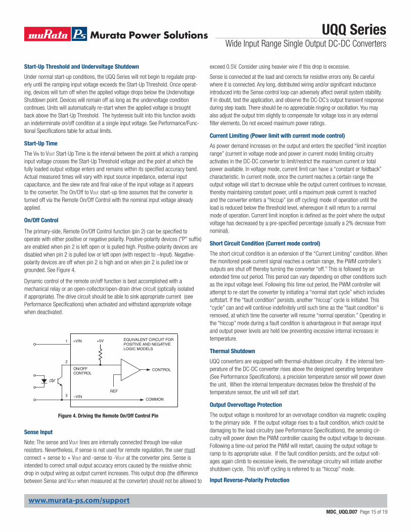
On/Off Control
The primary-side, Remote On/Off Control function (pin 2) can be specified to operate with either positive or negative polarity. Positive-polarity devices ("P" suffix) are enabled when pin 2 is left open or is pulled high. Positive-polarity devices are disabled when pin 2 is pulled low or left open (with respect to –Input). Negative-polarity devices are off when pin 2 is high and on when pin 2 is pulled low or grounded. See Figure 4.
Dynamic control of the remote on/off function is best accomplished with a mechanical relay or an open-collector/open-drain drive circuit (optically isolated if appropriate). The drive circuit should be able to sink appropriate current (see Performance Specifications) when activated and withstand appropriate voltage when deactivated.
Figure 4. Driving the Remote On/Off Control Pin
2
3
1 +5V
REF
+ VIN EQUIVALENT CIRCUIT FOR POSITIVE AND NEGATIVE LOGIC MODELS
CONTROL
–VIN
O N /O F F C O N TR O L
COMMON
exceed 0.5V. Consider using heavier wire if this drop is excessive.
Sense is connected at the load and corrects for resistive errors only. Be careful where it is connected. Any long, distributed wiring and/or significant inductance introduced into the Sense control loop can adversely affect overall system stability. If in doubt, test the application, and observe the DC-DC’s output transient response during step loads. There should be no appreciable ringing or oscillation. You may also adjust the output trim slightly to compensate for voltage loss in any external filter elements. Do not exceed maximum power ratings.
Current Limiting (Power limit with current mode control)
As power demand increases on the output and enters the specified “limit inception range” (current in voltage mode and power in current mode) limiting circuitry activates in the DC-DC converter to limit/restrict the maximum current or total power available. In voltage mode, current limit can have a “constant or foldback” characteristic. In current mode, once the current reaches a certain range the output voltage will start to decrease while the output current continues to increase, thereby maintaining constant power, until a maximum peak current is reached and the converter enters a “hiccup” (on off cycling) mode of operation until the load is reduced below the threshold level, whereupon it will return to a normal mode of operation. Current limit inception is defined as the point where the output voltage has decreased by a pre-specified percentage (usually a 2% decrease from nominal).
Short Circuit Condition (Current mode control)
The short circuit condition is an extension of the “Current Limiting” condition. When the monitored peak current signal reaches a certain range, the PWM controller’s outputs are shut off thereby turning the converter “off.” This is followed by an extended time out period. This period can vary depending on other conditions such as the input voltage level. Following this time out period, the PWM controller will attempt to re-start the converter by initiating a “normal start cycle” which includes softstart. If the “fault condition” persists, another “hiccup” cycle is initiated. This “cycle” can and will continue indefinitely until such time as the “fault condition” is removed, at which time the converter will resume “normal operation.” Operating in the “hiccup” mode during a fault condition is advantageous in that average input and output power levels are held low preventing excessive internal increases in temperature.
Thermal Shutdown
UQQ converters are equipped with thermal-shutdown circuitry. If the internal tem-perature of the DC-DC converter rises above the designed operating temperature (See Performance Specifications), a precision temperature sensor will power down the unit. When the internal temperature decreases below the threshold of the temperature sensor, the unit will self start.
Output Overvoltage Protection
The output voltage is monitored for an overvoltage condition via magnetic coupling to the primary side. If the output voltage rises to a fault condition, which could be damaging to the load circuitry (see Performance Specifications), the sensing cir-cuitry will power down the PWM controller causing the output voltage to decrease. Following a time-out period the PWM will restart, causing the output voltage to ramp to its appropriate value. If the fault condition persists, and the output volt-ages again climb to excessive levels, the overvoltage circuitry will initiate another shutdown cycle. This on/off cycling is referred to as “hiccup” mode.
Input Reverse-Polarity Protection
Sense Input
Note: The sense and Vout lines are internally connected through low-value resistors. Nevertheless, if sense is not used for remote regulation, the user must connect + sense to + Vout and -sense to -Vout at the converter pins. Sense is intended to correct small output accuracy errors caused by the resistive ohmic drop in output wiring as output current increases. This output drop (the difference between Sense and VOUT when measured at the converter) should not be allowed to
www.murata-ps.com/support
UQQ SeriesWide Input Range Single Output DC-DC Converters
MDC_UQQ.D07 Page 16 of 19
If the input-voltage polarity is accidentally reversed, an internal diode will become forward biased and likely draw excessive current from the power source. If the source is not current limited or the circuit appropriately fused, it could cause permanent damage to the converter.
Pre-Bias ProtectionFor applications where a pre-bias potential can be present at the output of the power module it is recommended that either blocking diodes are added in series with the Vout power lines or, a preferred solution is to use an OR-ing FET controller like the LM5050-1 High-Side & LM5051 Low-Side OR-ing FET Controller from TI. Starting the module into a pre-bias condition can cause permanent damage to the module.
Input Fusing
Certain applications and/or safety agencies may require the installation of fuses at the inputs of power conversion components. Fuses should also be used if the possibility of a sustained, non-current-limited, input-voltage polarity reversal exists. For MPS UQQ Series DC-DC Converters, fast-blow fuses are recommended with values no greater than twice the maximum input current.
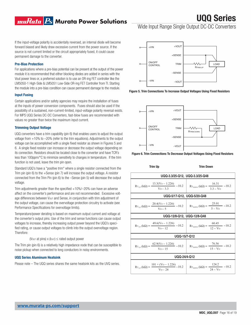
Trimming Output Voltage
UQQ converters have a trim capability (pin 6) that enables users to adjust the output voltage from +10% to –20% (refer to the trim equations). Adjustments to the output voltage can be accomplished with a single fixed resistor as shown in Figures 5 and 6. A single fixed resistor can increase or decrease the output voltage depending on its connection. Resistors should be located close to the converter and have TCR’s less than 100ppm/°C to minimize sensitivity to changes in temperature. If the trim function is not used, leave the trim pin open.
Standard UQQ’s have a "positive trim" where a single resistor connected from the Trim pin (pin 6) to the +Sense (pin 7) will increase the output voltage. A resistor connected from the Trim Pin (pin 6) to the –Sense (pin 5) will decrease the output voltage.
Trim adjustments greater than the specified +10%/–20% can have an adverse affect on the converter’s performance and are not recommended. Excessive volt-age differences between VOUT and Sense, in conjunction with trim adjustment of the output voltage, can cause the overvoltage protection circuitry to activate (see Performance Specifications for overvoltage limits).
Temperature/power derating is based on maximum output current and voltage at the converter’s output pins. Use of the trim and sense functions can cause output voltages to increase, thereby increasing output power beyond the UQQ’s speci-fied rating, or cause output voltages to climb into the output overvoltage region. Therefore:
(VOUT at pins) x (IOUT) ≤ rated output power
The Trim pin (pin 6) is a relatively high impedance node that can be susceptible to noise pickup when connected to long conductors in noisy environments.
UQQ Series Aluminum Heatsink
Please note – The UQQ series shares the same heatsink kits as the UVQ series.
LOADRTRIM DOWN
+VOUT+VIN
–VIN
ON/OFFCONTROL TRIM
+SENSE
–VOUT
–SENSE
LOADRTRIM UP
+VOUT+VIN
–VIN
ON/OFFCONTROL TRIM
+SENSE
–VOUT
–SENSE
Figure 5. Trim Connections To Increase Output Voltages Using Fixed Resistors
Figure 6. Trim Connections To Decrease Output Voltages Using Fixed Resistors
UP VO – 3.3RT (kΩ) = –10.2
13.3(VO – 1.226)
3.3 – VO RT (kΩ) = –10.2
16.31DOWN
UP VO – 5RT (kΩ) = –10.2
20.4(VO – 1.226)5 – VO
RT (kΩ) = –10.225.01
DOWN
UP VO – 12RT (kΩ) = –10.2
49.6(VO – 1.226)
12 – VO RT (kΩ) = –10.2
60.45DOWN
UP VO – 15RT (kΩ) = –10.2
62.9(VO – 1.226)15 – VO
RT (kΩ) = –10.276.56
DOWN
UQQ-3.3/25-Q12, UQQ-3.3/25-Q48
UQQ-5/17-Q12, UQQ-5/20-Q48
UQQ-12/8-Q12, UQQ-12/8-Q48
UQQ-15/7-Q12
UP VO – 24RT (kΩ) = –10.2
101 × (VO – 1.226)24 – VO
RT (kΩ) = –10.2124.2
DOWN
UQQ-24/4-Q12
Trim Up Trim Down
www.murata-ps.com/support
UQQ SeriesWide Input Range Single Output DC-DC Converters
MDC_UQQ.D07 Page 17 of 19
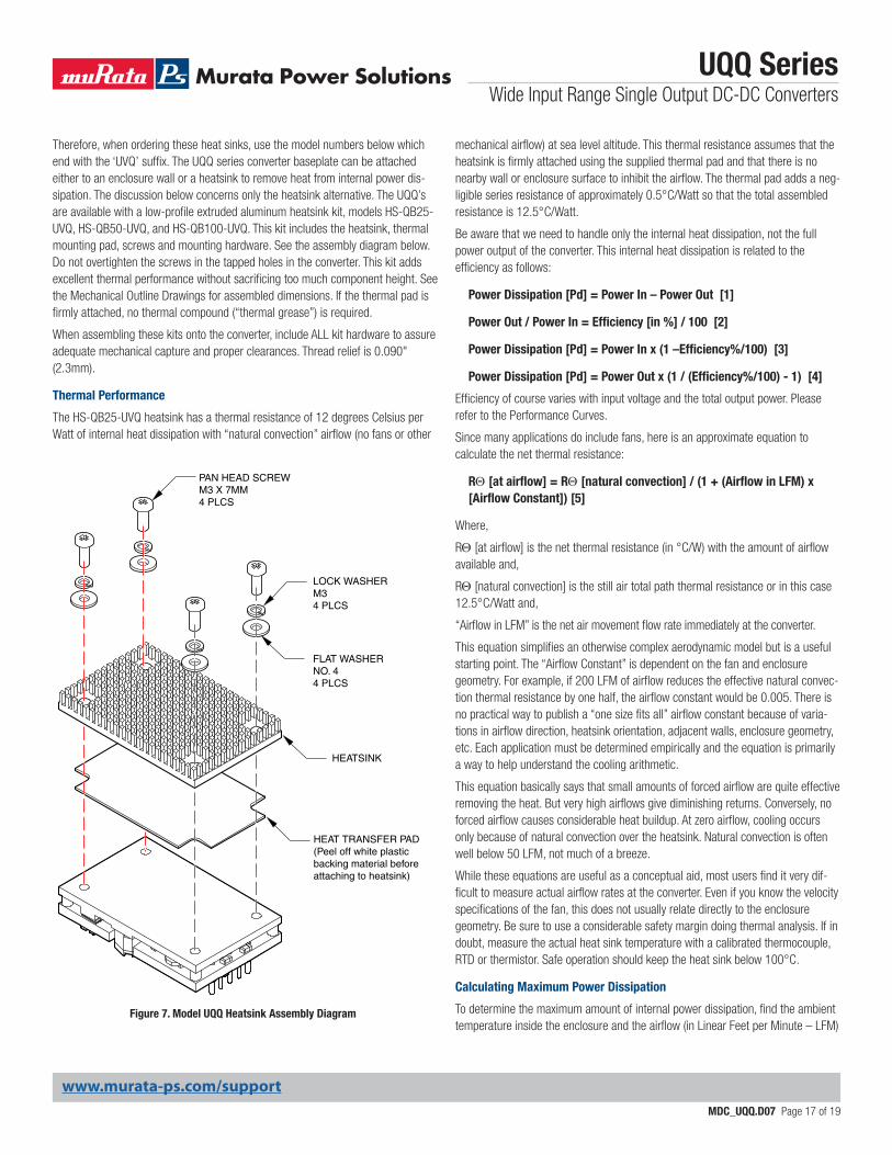
Figure 7. Model UQQ Heatsink Assembly Diagram
Therefore, when ordering these heat sinks, use the model numbers below which end with the ‘UVQ’ suffix. The UQQ series converter baseplate can be attached either to an enclosure wall or a heatsink to remove heat from internal power dis-sipation. The discussion below concerns only the heatsink alternative. The UQQ’s are available with a low-profile extruded aluminum heatsink kit, models HS-QB25-UVQ, HS-QB50-UVQ, and HS-QB100-UVQ. This kit includes the heatsink, thermal mounting pad, screws and mounting hardware. See the assembly diagram below. Do not overtighten the screws in the tapped holes in the converter. This kit adds excellent thermal performance without sacrificing too much component height. See the Mechanical Outline Drawings for assembled dimensions. If the thermal pad is firmly attached, no thermal compound (“thermal grease”) is required.
When assembling these kits onto the converter, include ALL kit hardware to assure adequate mechanical capture and proper clearances. Thread relief is 0.090" (2.3mm).
Thermal Performance
The HS-QB25-UVQ heatsink has a thermal resistance of 12 degrees Celsius per Watt of internal heat dissipation with “natural convection” airflow (no fans or other
mechanical airflow) at sea level altitude. This thermal resistance assumes that the heatsink is firmly attached using the supplied thermal pad and that there is no nearby wall or enclosure surface to inhibit the airflow. The thermal pad adds a neg-ligible series resistance of approximately 0.5°C/Watt so that the total assembled resistance is 12.5°C/Watt.
Be aware that we need to handle only the internal heat dissipation, not the full power output of the converter. This internal heat dissipation is related to the efficiency as follows:
Power Dissipation [Pd] = Power In – Power Out [1]
Power Out / Power In = Efficiency [in %] / 100 [2]
Power Dissipation [Pd] = Power In x (1 –Efficiency%/100) [3]
Power Dissipation [Pd] = Power Out x (1 / (Efficiency%/100) - 1) [4]
Efficiency of course varies with input voltage and the total output power. Please refer to the Performance Curves.
Since many applications do include fans, here is an approximate equation to calculate the net thermal resistance:
RQ [at airflow] = RQ [natural convection] / (1 + (Airflow in LFM) x [Airflow Constant]) [5]
Where,
RQ [at airflow] is the net thermal resistance (in °C/W) with the amount of airflow available and,
RQ [natural convection] is the still air total path thermal resistance or in this case 12.5°C/Watt and,
“Airflow in LFM” is the net air movement flow rate immediately at the converter.
This equation simplifies an otherwise complex aerodynamic model but is a useful starting point. The “Airflow Constant” is dependent on the fan and enclosure geometry. For example, if 200 LFM of airflow reduces the effective natural convec-tion thermal resistance by one half, the airflow constant would be 0.005. There is no practical way to publish a “one size fits all” airflow constant because of varia-tions in airflow direction, heatsink orientation, adjacent walls, enclosure geometry, etc. Each application must be determined empirically and the equation is primarily a way to help understand the cooling arithmetic.
This equation basically says that small amounts of forced airflow are quite effective removing the heat. But very high airflows give diminishing returns. Conversely, no forced airflow causes considerable heat buildup. At zero airflow, cooling occurs only because of natural convection over the heatsink. Natural convection is often well below 50 LFM, not much of a breeze.
While these equations are useful as a conceptual aid, most users find it very dif-ficult to measure actual airflow rates at the converter. Even if you know the velocity specifications of the fan, this does not usually relate directly to the enclosure geometry. Be sure to use a considerable safety margin doing thermal analysis. If in doubt, measure the actual heat sink temperature with a calibrated thermocouple, RTD or thermistor. Safe operation should keep the heat sink below 100°C.
Calculating Maximum Power Dissipation
To determine the maximum amount of internal power dissipation, find the ambient temperature inside the enclosure and the airflow (in Linear Feet per Minute – LFM)
PAN HEAD SCREWM3 X 7MM4 PLCS
LOCK WASHERM34 PLCS
FLAT WASHERNO. 44 PLCS
HEATSINK
HEAT TRANSFER PAD(Peel off white plasticbacking material before attaching to heatsink)
www.murata-ps.com/support
UQQ SeriesWide Input Range Single Output DC-DC Converters
MDC_UQQ.D07 Page 18 of 19
at the converter. Determine the expected heat dissipation using the Efficiency curves and the converter Input Voltage. You should also compensate for lower atmospheric pressure if your application altitude is considerably above sea level.
The general proceedure is to compute the expected temperature rise of the heat-sink. If the heatsink exceeds +100°C. either increase the airflow and/or reduce the power output. Start with this equation:
Internal Heat Dissipation [Pd in Watts] = (Ts – Ta)/RQ [at airflow] [6]
where “Ta” is the enclosure ambient air temperature and,
where “Ts” is the heatsink temperature and,
where “RQ [at airflow]” is a specific heat transfer thermal resistance (in degrees Celsius per Watt) for a particular heat sink at a set airflow rate. We have already estimated RQ [at airflow] in the equations above.
Note particularly that Ta is the air temperature inside the enclosure at the heatsink, not the outside air temperature. Most enclosures have higher internal tempera-tures, especially if the converter is “downwind” from other heat-producing circuits. Note also that this “Pd” term is only the internal heat dissipated inside the converter and not the total power output of the converter.
We can rearrange this equation to give an estimated temperature rise of the heatsink as follows:
Ts = (Pd x RQ [at airflow]) + Ta [7]These model numbers are correct for the UQQ series.
Heat Sink Example
Assume an efficiency of 92% and power output of 100 Watts. Using equation [4], Pd is about 8.7 Watts at an input voltage of 48 Volts. Using +30°C ambient tem-
perature inside the enclosure, we wish to limit the heat sink temperature to +90°C
maximum baseplate temperature to stay well away from thermal shutdown. The +90°C. figure also allows some margin in case the ambient climbs above +30°C or the input voltage varies, giving us less than 92% efficiency. The heat sink and airflow combination must have the following characteristics:
8.7 W = (90-30) / RQ[airflow] or, RQ[airflow] = 60/8.7 = 6.9°C/W
Since the ambient thermal resistance of the heatsink and pad is 12.5°C/W, we need additional forced cooling to get us down to 6.9°C/W. Using a hypothetical airflow constant of 0.005, we can rearrange equation [5] as follows:
(Required Airflow, LFM) x (Airflow Constant) = RQ[Nat.Convection] / RQ[at airflow] –1, or,
(Required Airflow, LFM) x (Airflow Constant) = 12.5/6.9 –1 = 0.81
and, rearranging again,
(Required Airflow, LFM) = 0.81/0.005 = 162 LFM
162 LFM is the minumum airflow to keep the heatsink below +90°C. Increase the airflow to several hundred LFM to reduce the heatsink temperature further and improve life and reliability.
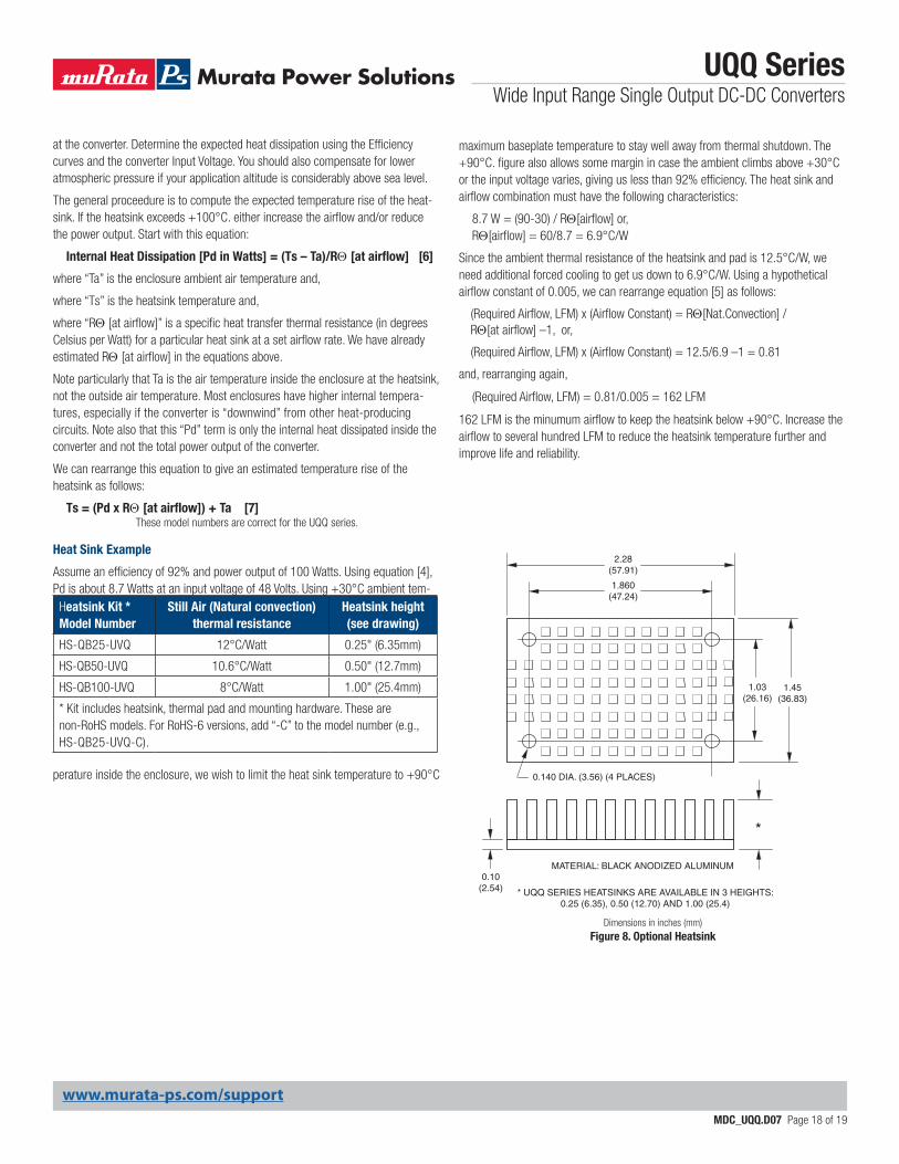
Heatsink Kit * Model Number
Still Air (Natural convection) thermal resistance
Heatsink height (see drawing)
HS-QB25-UVQ 12°C/Watt 0.25" (6.35mm)
HS-QB50-UVQ 10.6°C/Watt 0.50" (12.7mm)
HS-QB100-UVQ 8°C/Watt 1.00" (25.4mm)
* Kit includes heatsink, thermal pad and mounting hardware. These are non-RoHS models. For RoHS-6 versions, add “-C” to the model number (e.g., HS-QB25-UVQ-C).
0.10 (2.54)
*
* UQQ SERIES HEATSINKS ARE AVAILABLE IN 3 HEIGHTS:0.25 (6.35), 0.50 (12.70) AND 1.00 (25.4)
1.45 (36.83)
2.28 (57.91)
MATERIAL: BLACK ANODIZED ALUMINUM
1.03 (26.16)
1.860 (47.24)
0.140 DIA. (3.56) (4 PLACES)
Dimensions in inches (mm)Figure 8. Optional Heatsink
www.murata-ps.com/support
Murata Power Solutions, Inc. makes no representation that the use of its products in the circuits described herein, or the use of other technical information contained herein, will not infringe upon existing or future patent rights. The descriptions contained herein do not imply the granting of licenses to make, use, or sell equipment constructed in accordance therewith. Specifications are subject to change without notice. © 2020 Murata Power Solutions, Inc.
Murata Power Solutions, Inc. 129 Flanders Road, Westborough, MA 01581.ISO 9001 and 14001 REGISTERED
This product is subject to the following operating requirements and the Life and Safety Critical Application Sales Policy: Refer to: https://www.murata-ps.com/requirements/
UQQ SeriesWide Input Range Single Output DC-DC Converters
MDC_UQQ.D07 Page 19 of 19
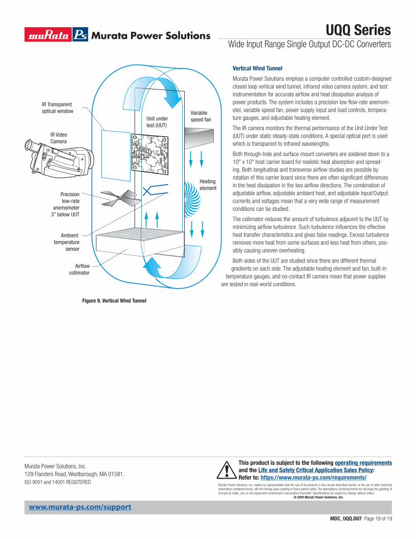
Figure 9. Vertical Wind Tunnel
IR Video Camera
IR Transparentoptical window Variable
speed fan
Heating element
Ambient temperature
sensor
Airflowcollimator
Precisionlow-rate
anemometer3” below UUT
Unit undertest (UUT)
Vertical Wind Tunnel
Murata Power Solutions employs a computer controlled custom-designed closed loop vertical wind tunnel, infrared video camera system, and test instrumentation for accurate airflow and heat dissipation analysis of power products. The system includes a precision low flow-rate anemom-eter, variable speed fan, power supply input and load controls, tempera-ture gauges, and adjustable heating element.
The IR camera monitors the thermal performance of the Unit Under Test (UUT) under static steady-state conditions. A special optical port is used which is transparent to infrared wavelengths.
Both through-hole and surface mount converters are soldered down to a 10" x 10" host carrier board for realistic heat absorption and spread-ing. Both longitudinal and transverse airflow studies are possible by rotation of this carrier board since there are often significant differences in the heat dissipation in the two airflow directions. The combination of adjustable airflow, adjustable ambient heat, and adjustable Input/Output currents and voltages mean that a very wide range of measurement conditions can be studied.
The collimator reduces the amount of turbulence adjacent to the UUT by minimizing airflow turbulence. Such turbulence influences the effective heat transfer characteristics and gives false readings. Excess turbulence removes more heat from some surfaces and less heat from others, pos-sibly causing uneven overheating.
Both sides of the UUT are studied since there are different thermal gradients on each side. The adjustable heating element and fan, built-in
temperature gauges, and no-contact IR camera mean that power supplies are tested in real-world conditions.