Embed Size (px)
Citation preview
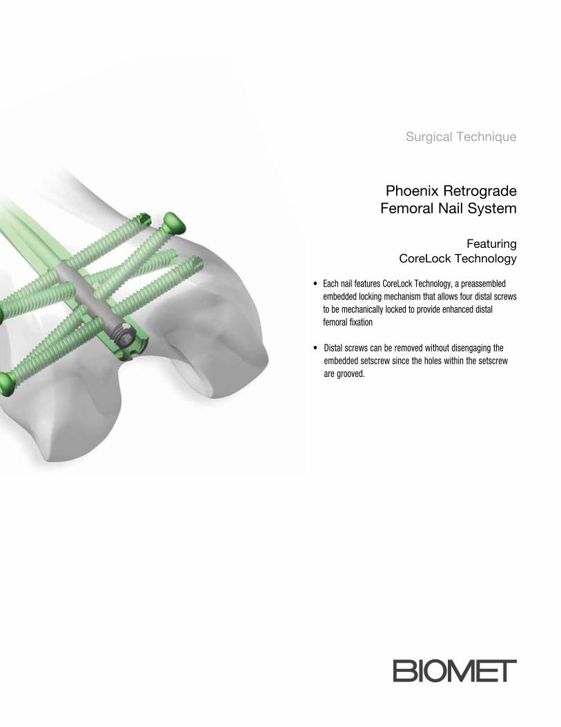
Surgical Technique
Phoenix Retrograde Femoral Nail System
Featuring CoreLock Technology
• Each nail features CoreLock Technology, a preassembled embedded locking mechanism that allows four distal screws to be mechanically locked to provide enhanced distal femoral fixation
• Distal screws can be removed without disengaging the embedded setscrew since the holes within the setscrew are grooved.

Contents
Introduction .................................................. Page 1
Design Features............................................ Page 3
Surgical Technique ...................................... Page 6
Product Ordering Information ....................... Page 21
Indications And Contraindications ................. Page 24

1
Introduction
The Phoenix Retrograde Femoral Nail System features CoreLock
Technology, a preassembled, embedded locking mechanism that
allows the four distal screws (2- transverse and 2-oblique) to be
mechanically locked to provide enhanced distal femoral fixation. This
universal retrograde femoral nail is composed of titanium alloy that
incorporates a 1.8m radius of curvature and a 5° distal bend, that is
initiated at 45mm from the driving end. Nails are available in outer
diameters of 9mm, 10.5mm, 12mm and 13.5mm for applications
in a wide variety of patients in lengths of 240mm-460mm in 20mm
increments. Additionally, the system features a strong, lightweight
Radiolucent Targeting Arm that permits radiographic visualization
in multiple planes and allows for accurate transverse and/or
oblique targeting. With its easy to use color-coded instrumentation
conveniently contained in a single tray and its innovative implant
design, the Phoenix Retrograde Femoral Nail System is designed to
address both patient and surgeon needs.
This material represents the surgical technique utilized by Michael
S. Sirkin, M.D., Cory A. Collinge, M.D. and Kenneth J. Koval,
M.D. Biomet does not practice medicine. The treating surgeon is
responsible for determining the appropriate treatment, technique(s),
and product(s) for each individual patient.
2
Indications and Contraindications
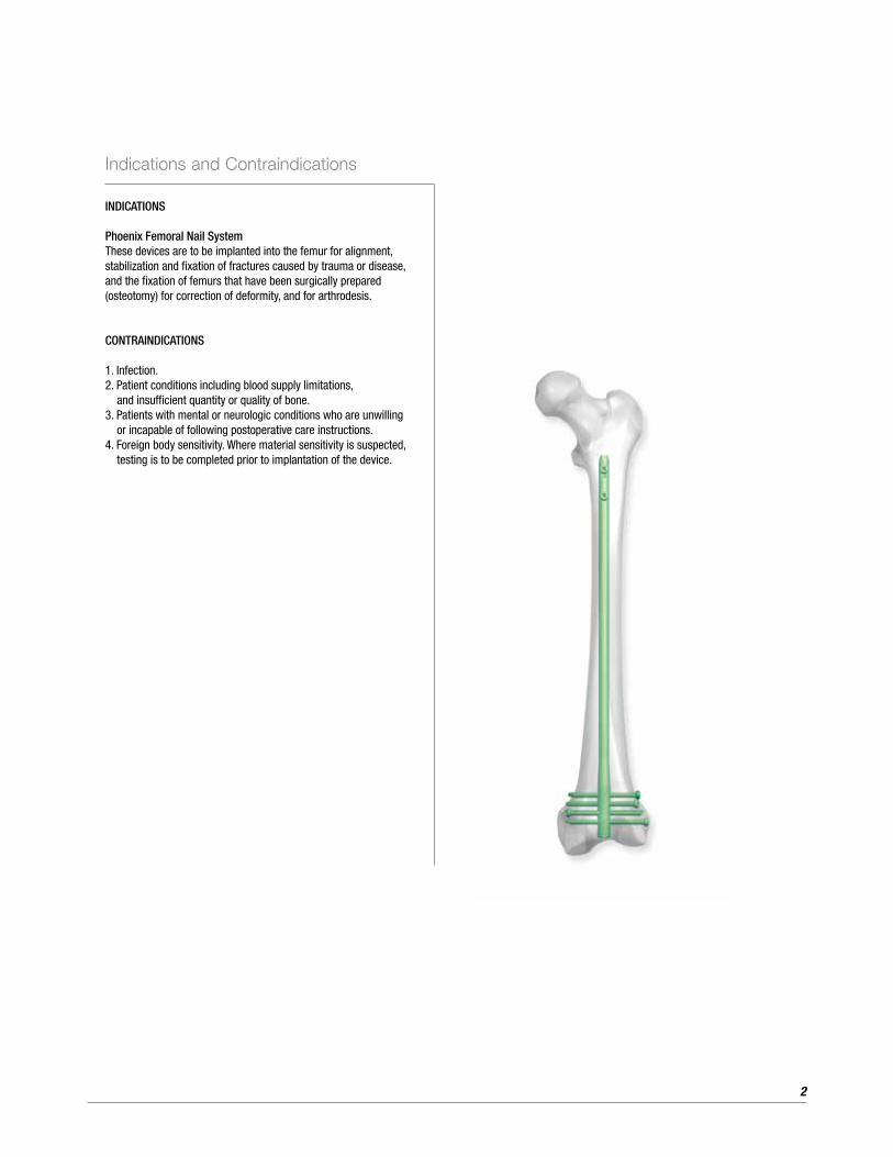
INDICATIONS
Phoenix Femoral Nail SystemThese devices are to be implanted into the femur for alignment, stabilization and fixation of fractures caused by trauma or disease, and the fixation of femurs that have been surgically prepared (osteotomy) for correction of deformity, and for arthrodesis.
CONTRAINDICATIONS
1. Infection.2. Patient conditions including blood supply limitations, and insufficient quantity or quality of bone.3. Patients with mental or neurologic conditions who are unwilling or incapable of following postoperative care instructions.4. Foreign body sensitivity. Where material sensitivity is suspected, testing is to be completed prior to implantation of the device.
3
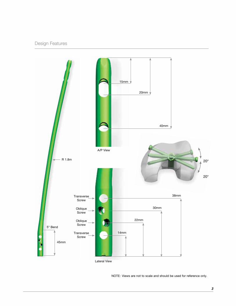
Design Features
5° Bend
30mm
45mm
22mm
14mmTransverse Screw
Oblique Screw
Oblique Screw
Transverse Screw
R 1.8m
NOTE: Views are not to scale and should be used for reference only.
20°
20°
15mm
20mm
40mm
38mm
A/P View
Lateral View

4
Design Features (Continued)
Nail diameters and length:
• 9mm, 10.5mm, 12mm and 13.5mm
• Offered in lengths ranging from 240mm - 460mm
(20mm increments)
• Distal diameter for 9mm, 10.5mm, and 12mm nails
is 12mm
• Distal diameter for 13.5mm nail is 13.5mm
9mm 10.5mm 12mm 13.5mm
The Phoenix Retrograde Femoral Nail features CoreLock
Technology, a preassembled embedded locking mechanism that
allows the four distal screws to be mechanically locked to provide
enhanced distal femoral fixation.
Since the holes within the embedded setscrew are
grooved, distal screw removal can be achieved
without disengaging the embedded setscrew.
5
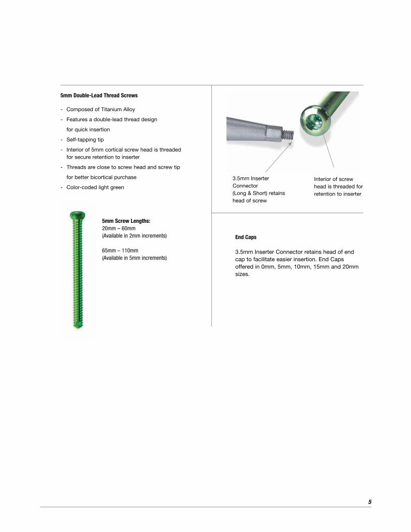
End Caps
3.5mm Inserter Connector retains head of end cap to facilitate easier insertion. End Caps offered in 0mm, 5mm, 10mm, 15mm and 20mm sizes.
5mm Screw Lengths:20mm – 60mm(Available in 2mm increments)
65mm – 110mm(Available in 5mm increments)
3.5mm Inserter Connector (Long & Short) retains head of screw
Interior of screw head is threaded for retention to inserter
5mm Double-Lead Thread Screws
- Composed of Titanium Alloy
- Features a double-lead thread design
for quick insertion
- Self-tapping tip
- Interior of 5mm cortical screw head is threaded for secure retention to inserter
- Threads are close to screw head and screw tip
for better bicortical purchase
- Color-coded light green
6
Surgical Technique
Step 2. Incision
Incise a 3-4cm midline incision from the inferior border to the
patella. Next, perform a medial parapatella capsular incision and
retract the patellar tendon laterally. Articular cartilage should be
visualized to allow for irrigation and removal of reaming debris.
Alternatively, the patella tendon can be split.
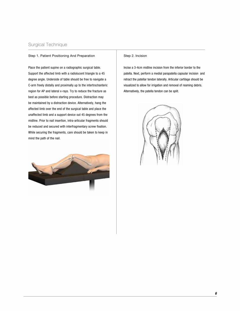
Step 1. Patient Positioning And Preparation
Place the patient supine on a radiographic surgical table.
Support the affected limb with a radiolucent triangle to a 45
degree angle. Underside of table should be free to navigate a
C-arm freely distally and proximally up to the intertrochanteric
region for AP and lateral x-rays. Try to reduce the fracture as
best as possible before starting procedure. Distraction may
be maintained by a distraction device. Alternatively, hang the
affected limb over the end of the surgical table and place the
unaffected limb and a support device out 45 degrees from the
midline. Prior to nail insertion, intra-articular fragments should
be reduced and secured with interfragmentary screw fixation.
While securing the fragments, care should be taken to keep in
mind the path of the nail.
7
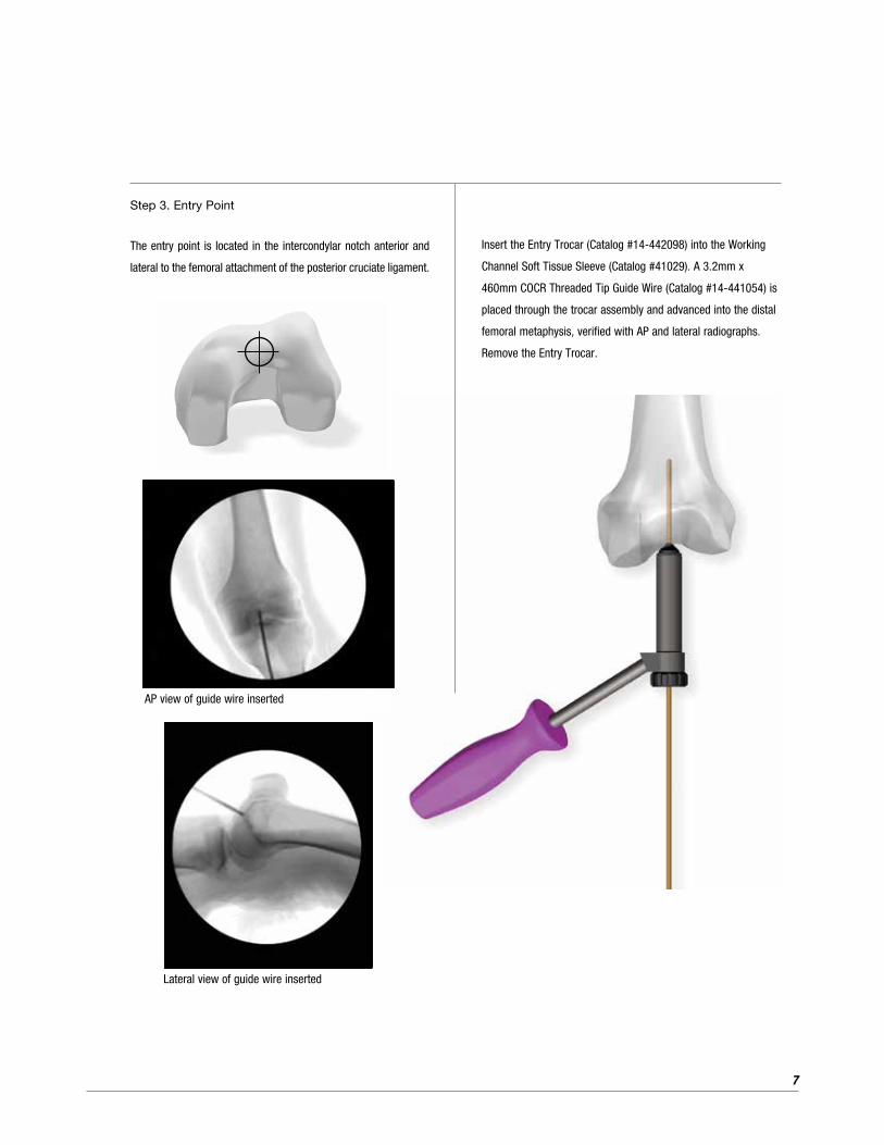
Insert the Entry Trocar (Catalog #14-442098) into the Working
Channel Soft Tissue Sleeve (Catalog #41029). A 3.2mm x
460mm COCR Threaded Tip Guide Wire (Catalog #14-441054) is
placed through the trocar assembly and advanced into the distal
femoral metaphysis, verified with AP and lateral radiographs.
Remove the Entry Trocar.
Step 3. Entry Point
The entry point is located in the intercondylar notch anterior and
lateral to the femoral attachment of the posterior cruciate ligament.
AP view of guide wire inserted
Lateral view of guide wire inserted
8
Surgical Technique (Continued)
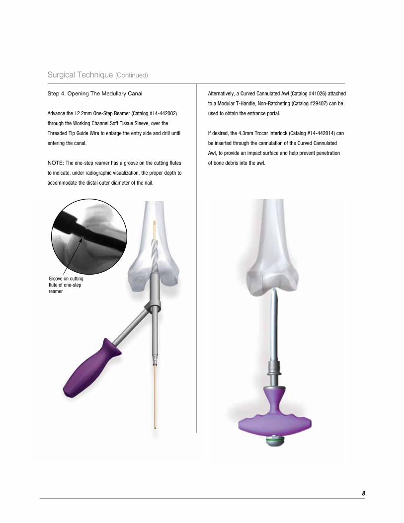
Alternatively, a Curved Cannulated Awl (Catalog #41026) attached
to a Modular T-Handle, Non-Ratcheting (Catalog #29407) can be
used to obtain the entrance portal.
If desired, the 4.3mm Trocar Interlock (Catalog #14-442014) can
be inserted through the cannulation of the Curved Cannulated
Awl, to provide an impact surface and help prevent penetration
of bone debris into the awl.
Step 4. Opening The Medullary Canal
Advance the 12.2mm One-Step Reamer (Catalog #14-442002)
through the Working Channel Soft Tissue Sleeve, over the
Threaded Tip Guide Wire to enlarge the entry side and drill until
entering the canal.
NOTE: The one-step reamer has a groove on the cutting flutes
to indicate, under radiographic visualization, the proper depth to
accommodate the distal outer diameter of the nail.
Groove on cutting flute of one-step reamer

9
Step 5. Fracture Reduction And Guide Wire Placement
Fracture reduction is performed manually, with use of radiograph
images to aide with positioning. If the canal is to be reamed, a
3.0mm x 98cm Bead Tip Guide Wire (Catalog #27922) is inserted
into the intramedullary canal and advanced past the fracture site,
into the proximal femur. Confirm position of Guide Wire to be
center – center in the AP and lateral views.
To help facilitate Guide Wire passage through the fracture site,
the Keyless Chuck T-Handle (Catalog #14-442078) can be used.

10
Surgical Technique (Continued)
In the case of a non-union, where the path to the canal is blocked
and unlikely to advance a guide wire or entry reamer across the
fracture site, a Pseudarthrosis Pin Straight (Catalog #14-442073)
or Curved (Catalog #14-442074) can be used to create an opening
for the passage of a guide wire for canal reaming.
5mm
In the event of a difficult fracture reduction, the 8.5mm Fracture
Reducer (Bowed) (Catalog #14-442068) can be used to facilitate
Guide Wire insertion and fracture reduction. In patients with tight
canals, reaming to 9.5mm may help facilitate passage of reducer.

11
40
39
38
Step 6. Determining Nail Length
A second Guide Wire of equal length can be used to measure the
length of the medullary canal or a Medullary Canal and Length
Estimator (Catalog #14-442075) can be used to determine nail
diameter and length. The appropriate nail length should be
inserted passed Blumensaat’s Line and usually approximating
1cm proximal to the lesser trochanter. The 98cm Telescoping
Nail Measuring Gage (Catalog #14-440067) is placed over the
3.0 Bead Tip Guide Wire with the foot resting on the articular
surface. With the Guide Wire resting in the desired proximal
femur, the telescoping tube is extended to the end of the Guide
Wire. To measure nail length, a direct reading can be made at
the junction of the two tubes. The nail should be countersunk to
prevent any impingement. The nail length chosen should be at
least 1cm shorter than the measured medullary canal to allow
countersinking of the nail.
12
Surgical Technique (Continued)
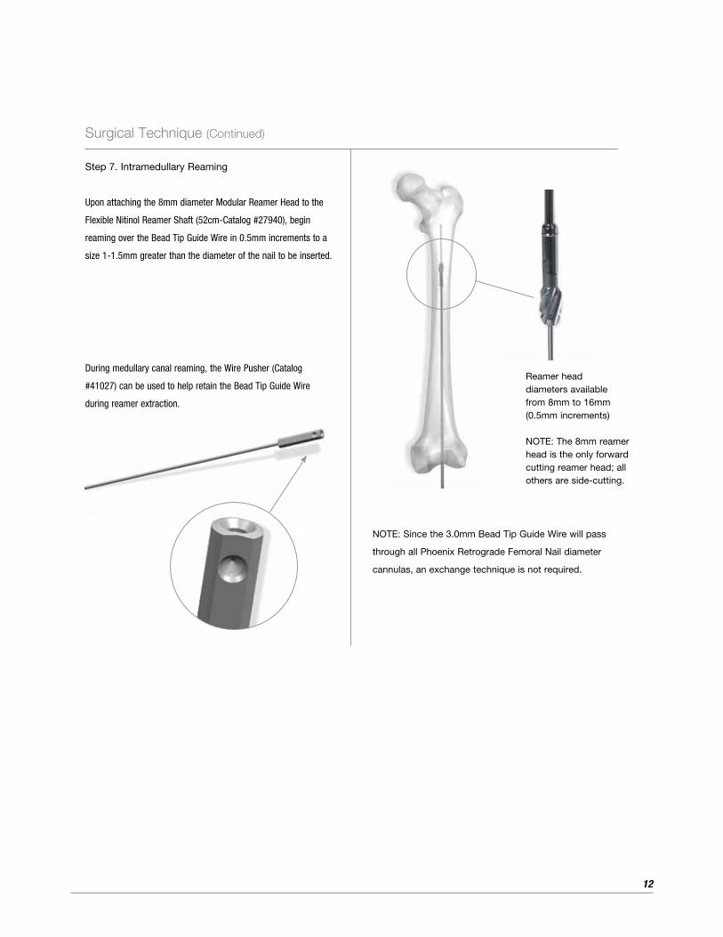
Step 7. Intramedullary Reaming
Upon attaching the 8mm diameter Modular Reamer Head to the
Flexible Nitinol Reamer Shaft (52cm-Catalog #27940), begin
reaming over the Bead Tip Guide Wire in 0.5mm increments to a
size 1-1.5mm greater than the diameter of the nail to be inserted.
Reamer head diameters available from 8mm to 16mm (0.5mm increments)
NOTE: The 8mm reamer head is the only forward cutting reamer head; all others are side-cutting.
During medullary canal reaming, the Wire Pusher (Catalog
#41027) can be used to help retain the Bead Tip Guide Wire
during reamer extraction.
NOTE: Since the 3.0mm Bead Tip Guide Wire will pass
through all Phoenix Retrograde Femoral Nail diameter
cannulas, an exchange technique is not required.
13
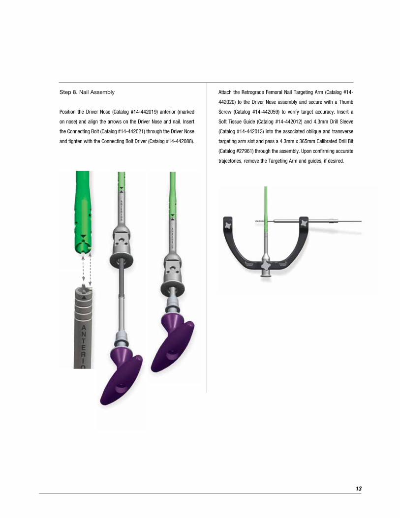
Step 8. Nail Assembly
Position the Driver Nose (Catalog #14-442019) anterior (marked
on nose) and align the arrows on the Driver Nose and nail. Insert
the Connecting Bolt (Catalog #14-442021) through the Driver Nose
and tighten with the Connecting Bolt Driver (Catalog #14-442088).
Attach the Retrograde Femoral Nail Targeting Arm (Catalog #14-
442020) to the Driver Nose assembly and secure with a Thumb
Screw (Catalog #14-442059) to verify target accuracy. Insert a
Soft Tissue Guide (Catalog #14-442012) and 4.3mm Drill Sleeve
(Catalog #14-442013) into the associated oblique and transverse
targeting arm slot and pass a 4.3mm x 365mm Calibrated Drill Bit
(Catalog #27961) through the assembly. Upon confirming accurate
trajectories, remove the Targeting Arm and guides, if desired.
14
Surgical Technique (Continued)
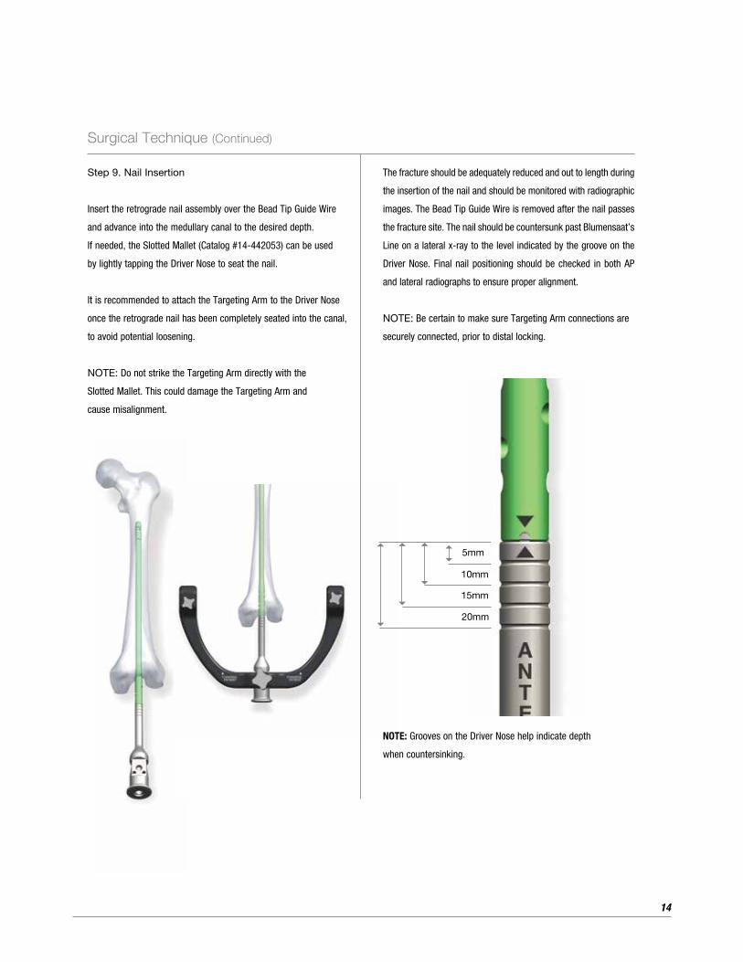
NOTE: Grooves on the Driver Nose help indicate depth
when countersinking.
5mm
10mm
15mm
20mm
The fracture should be adequately reduced and out to length during
the insertion of the nail and should be monitored with radiographic
images. The Bead Tip Guide Wire is removed after the nail passes
the fracture site. The nail should be countersunk past Blumensaat’s
Line on a lateral x-ray to the level indicated by the groove on the
Driver Nose. Final nail positioning should be checked in both AP
and lateral radiographs to ensure proper alignment.
NOTE: Be certain to make sure Targeting Arm connections are
securely connected, prior to distal locking.
56
5
6
5
6
5
6
Step 9. Nail Insertion
Insert the retrograde nail assembly over the Bead Tip Guide Wire
and advance into the medullary canal to the desired depth.
If needed, the Slotted Mallet (Catalog #14-442053) can be used
by lightly tapping the Driver Nose to seat the nail.
It is recommended to attach the Targeting Arm to the Driver Nose
once the retrograde nail has been completely seated into the canal,
to avoid potential loosening.
NOTE: Do not strike the Targeting Arm directly with the
Slotted Mallet. This could damage the Targeting Arm and
cause misalignment.
15
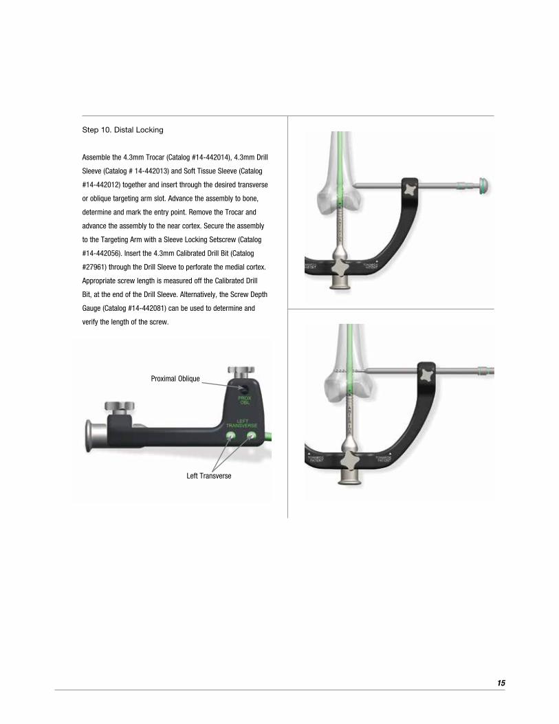
Proximal Oblique
Left Transverse
Step 10. Distal Locking
Assemble the 4.3mm Trocar (Catalog #14-442014), 4.3mm Drill
Sleeve (Catalog # 14-442013) and Soft Tissue Sleeve (Catalog
#14-442012) together and insert through the desired transverse
or oblique targeting arm slot. Advance the assembly to bone,
determine and mark the entry point. Remove the Trocar and
advance the assembly to the near cortex. Secure the assembly
to the Targeting Arm with a Sleeve Locking Setscrew (Catalog
#14-442056). Insert the 4.3mm Calibrated Drill Bit (Catalog
#27961) through the Drill Sleeve to perforate the medial cortex.
Appropriate screw length is measured off the Calibrated Drill
Bit, at the end of the Drill Sleeve. Alternatively, the Screw Depth
Gauge (Catalog #14-442081) can be used to determine and
verify the length of the screw.

16
Surgical Technique (Continued)
The line marked “Femoral” on the 3.5mm Inserter, Long indicates
when the screw head is fully seated (Ensure the Soft Tissue Sleeve
is firmly against bone).
Attach the 3.5mm Inserter Connector, Long (Catalog #14-441043)
through the cannula of the either the Straight or T-Handle and
connect the 3.5mm Inserter, Long (Catalog #14-441044). Retain
the screw to the threaded hex tip of the Inserter Connector and
turn the knob in a clockwise fashion. Insert the screw through the
Soft Tissue Guide and into bone. Repeat the locking procedure to
insert additional screws.
When distal screw insertion is complete, insert the 4mm Hex
Driver through the Driver Nose into the distal aspect of the nail
and turn in a clockwise motion to lock the distal screws with the
preassembled, embedded setscrew/locking mechanism. When
complete, remove the hex driver and targeting arm assembly.
NOTE: For final tightening 5mm screws, the 3.5mm Solid Inserter-
Long (Catalog #14-441051) or the 3.5mm Solid Inserter-Short
(Catalog #14-441052) should be used.
17
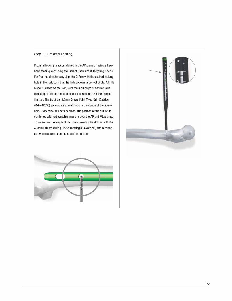
Step 11. Proximal Locking
Proximal locking is accomplished in the AP plane by using a free-
hand technique or using the Biomet Radiolucent Targeting Device.
For free-hand technique, align the C-Arm with the desired locking
hole in the nail, such that the hole appears a perfect circle. A knife
blade is placed on the skin, with the incision point verified with
radiographic image and a 1cm incision is made over the hole in
the nail. The tip of the 4.5mm Crowe Point Twist Drill (Catalog
#14-442095) appears as a solid circle in the center of the screw
hole. Proceed to drill both cortices. The position of the drill bit is
confirmed with radiographic image in both the AP and ML planes.
To determine the length of the screw, overlay the drill bit with the
4.5mm Drill Measuring Sleeve (Catalog #14-442096) and read the
screw measurement at the end of the drill bit.
50
40
30
18
Surgical Technique (Continued)
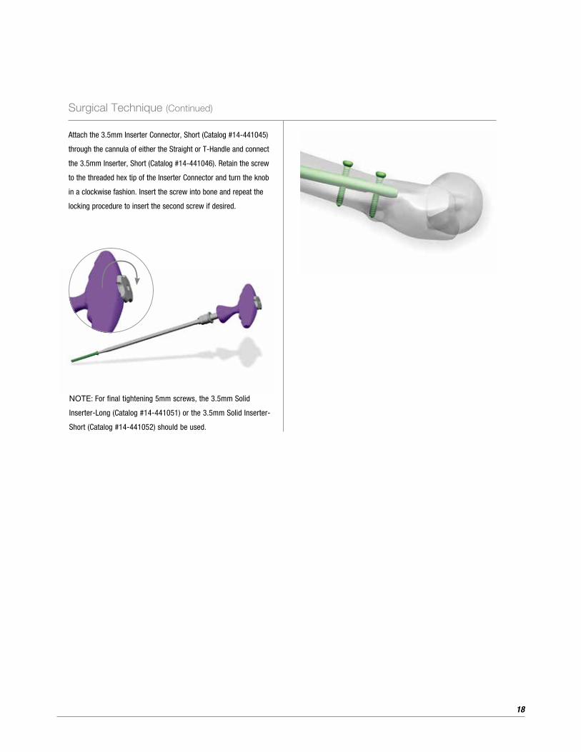
Attach the 3.5mm Inserter Connector, Short (Catalog #14-441045)
through the cannula of either the Straight or T-Handle and connect
the 3.5mm Inserter, Short (Catalog #14-441046). Retain the screw
to the threaded hex tip of the Inserter Connector and turn the knob
in a clockwise fashion. Insert the screw into bone and repeat the
locking procedure to insert the second screw if desired.
NOTE: For final tightening 5mm screws, the 3.5mm Solid
Inserter-Long (Catalog #14-441051) or the 3.5mm Solid Inserter-
Short (Catalog #14-441052) should be used.

19
End Cap Insertion
If desired, one of five different profile end caps ranging from 0mm
to 20mm (available in 5mm increments) can be inserted into the
distal end the Phoenix Retrograde Femoral Nail to prevent bony
in-growth. Retain the end cap to the Inserter Connector assembly
and insert into the distal end of the nail.
NOTE: For final tightening end caps, the 3.5mm Solid Inserter-
Long (Catalog #14-441051) or the 3.5mm Solid Inserter-Short
(Catalog #14-441052) should be used.
20
Surgical Technique (Continued)
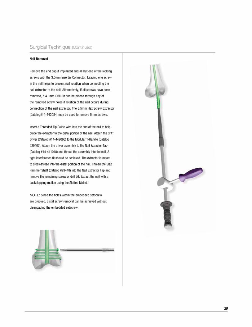
Nail Removal
Remove the end cap if implanted and all but one of the locking
screws with the 3.5mm Inserter Connector. Leaving one screw
in the nail helps to prevent nail rotation when connecting the
nail extractor to the nail. Alternatively, if all screws have been
removed, a 4.3mm Drill Bit can be placed through any of
the removed screw holes if rotation of the nail occurs during
connection of the nail extractor. The 3.5mm Hex Screw Extractor
(Catalog#14-442084) may be used to remove 5mm screws.
Insert a Threaded Tip Guide Wire into the end of the nail to help
guide the extractor to the distal portion of the nail. Attach the 3/4”
Driver (Catalog #14-442066) to the Modular T-Handle (Catalog
#29407). Attach the driver assembly to the Nail Extractor Tap
(Catalog #14-441048) and thread the assembly into the nail. A
tight interference fit should be achieved. The extractor is meant
to cross-thread into the distal portion of the nail. Thread the Slap
Hammer Shaft (Catalog #29448) into the Nail Extractor Tap and
remove the remaining screw or drill bit. Extract the nail with a
backslapping motion using the Slotted Mallet.
NOTE: Since the holes within the embedded setscrew
are grooved, distal screw removal can be achieved without
disengaging the embedded setscrew.

21
Product Ordering Information
9mm Retrograde Femoral Nails
Catalog# Description
14-444124 Retrograde Femoral Nail, 9.0mm x 240mm
14-444126 Retrograde Femoral Nail, 9.0mm x 260mm
14-444128 Retrograde Femoral Nail, 9.0mm x 280mm
14-444130 Retrograde Femoral Nail, 9.0mm x 300mm
14-444132 Retrograde Femoral Nail, 9.0mm x 320mm
14-444134 Retrograde Femoral Nail, 9.0mm x 340mm
14-444136 Retrograde Femoral Nail, 9.0mm x 360mm
14-444138 Retrograde Femoral Nail, 9.0mm x 380mm
14-444140 Retrograde Femoral Nail, 9.0mm x 400mm
14-444142 Retrograde Femoral Nail, 9.0mm x 420mm
14-444144 Retrograde Femoral Nail, 9.0mm x 440mm
14-444146 Retrograde Femoral Nail, 9.0mm x 460mm
10.5mm Retrograde Femoral Nails
Catalog# Description
14-444224 Retrograde Femoral Nail, 10.5mm x 240mm
14-444226 Retrograde Femoral Nail, 10.5mm x 260mm
14-444228 Retrograde Femoral Nail, 10.5mm x 280mm
14-444230 Retrograde Femoral Nail, 10.5mm x 300mm
14-444232 Retrograde Femoral Nail, 10.5mm x 320mm
14-444234 Retrograde Femoral Nail, 10.5mm x 340mm
14-444236 Retrograde Femoral Nail, 10.5mm x 360mm
14-444238 Retrograde Femoral Nail, 10.5mm x 380mm
14-444240 Retrograde Femoral Nail, 10.5mm x 400mm
14-444242 Retrograde Femoral Nail, 10.5mm x 420mm
14-444244 Retrograde Femoral Nail, 10.5mm x 440mm
14-444246 Retrograde Femoral Nail, 10.5mm x 460mm
12mm Retrograde Femoral Nails
Catalog# Description
14-444324 Retrograde Femoral Nail, 12mm x 240mm
14-444326 Retrograde Femoral Nail, 12mm x 260mm
14-444328 Retrograde Femoral Nail, 12mm x 280mm
14-444330 Retrograde Femoral Nail, 12mm x 300mm
14-444332 Retrograde Femoral Nail, 12mm x 320mm
14-444334 Retrograde Femoral Nail, 12mm x 340mm
14-444336 Retrograde Femoral Nail, 12mm x 360mm
14-444338 Retrograde Femoral Nail, 12mm x 380mm
14-444340 Retrograde Femoral Nail, 12mm x 400mm
14-444342 Retrograde Femoral Nail, 12mm x 420mm
14-444344 Retrograde Femoral Nail, 12mm x 440mm
14-444346 Retrograde Femoral Nail, 12mm x 460mm
13.5mm Retrograde Femoral Nails
Catalog# Description
14-444424 Retrograde Femoral Nail, 13.5mm x 240mm
14-444426 Retrograde Femoral Nail, 13.5mm x 260mm
14-444428 Retrograde Femoral Nail, 13.5mm x 280mm
14-444430 Retrograde Femoral Nail, 13.5mm x 300mm
14-444432 Retrograde Femoral Nail, 13.5mm x 320mm
14-444434 Retrograde Femoral Nail, 13.5mm x 340mm
14-444436 Retrograde Femoral Nail, 13.5mm x 360mm
14-444438 Retrograde Femoral Nail, 13.5mm x 380mm
14-444440 Retrograde Femoral Nail, 13.5mm x 400mm
14-444442 Retrograde Femoral Nail, 13.5mm x 420mm
14-444444 Retrograde Femoral Nail, 13.5mm x 440mm
14-444446 Retrograde Femoral Nail, 13.5mm x 460mm

22
Product Ordering Information (Continued)
End Caps
Catalog# Description
14-444180 0mm Offset End Cap
14-444181 12mm x 5mm Offset End Cap
14-444182 12mm x 10mm Offset End Cap
14-444183 12mm x 15mm Offset End Cap
14-444184 12mm x 20mm Offset End Cap
14-444191 13.5mm x 5mm Offset End Cap
14-444192 13.5mm x 10mm Offset End Cap
14-444193 13.5mm x 15mm Offset End Cap
14-444194 13.5mm x 20mm Offset End Cap
Disposables
Catalog# Description
27922 3.0mm x 98mm Bead Tip Guide Wire
27961 4.3mm x 365mm Calibrated Drill
471830 Radiolucent Targeting Device
471847 4.5mm Radiolucent Targeting Device Twist Drill
14-442002 12.2mm One-Step Reamer
14-442095 4.5mm Crowe Point Twist Drill
14-441054 3.2mm x 460mm COCR Thd Tip
5mm Double-Lead Thread Screws
Catalog# Description
14-405020 5mm x 20mm screw
14-405022 5mm x 22mm screw
14-405024 5mm x 24mm screw
14-405026 5mm x 26mm screw
14-405028 5mm x 28mm screw
14-405030 5mm x 30mm screw
14-405032 5mm x 32mm screw
14-405034 5mm x 34mm screw
14-405036 5mm x 36mm screw
14-405038 5mm x 38mm screw
14-405040 5mm x 40mm screw
14-405042 5mm x 42mm screw
14-405044 5mm x 44mm screw
14-405046 5mm x 46mm screw
14-405048 5mm x 48mm screw
14-405050 5mm x 50mm screw
14-405052 5mm x 52mm screw
14-405054 5mm x 54mm screw
14-405056 5mm x 56mm screw
14-405058 5mm x 58mm screw
14-405060 5mm x 60mm screw
14-405065 5mm x 65mm screw
14-405070 5mm x 70mm screw
14-405075 5mm x 75mm screw
14-405080 5mm x 80mm screw
14-405085 5mm x 85mm screw
14-405090 5mm x 90mm screw
14-405095 5mm x 95mm screw
14-405100 5mm x 100mm screw
14-405105 5mm x 105mm screw
14-405110 5mm x 110mm screw

23
Instruments
Catalog# Description
27939 NiTi Reamer Extension
27940 52cm Reamer Shaft
27977 Stryker†/AO Power Adapter
29407 Modular T-Handle, Non-Ratcheting
29408 Modular Straight Handle, Ratcheting
29448 Slap Hammer Shaft
41024 Hex Driver 4mm
41026 Curved Cannulated Awl
41027 Wire Pusher
41029 Working Channel Soft Tissue Sleeve
467534 8.0mm Reamer Head
467536 8.5mm Reamer Head
467538 9.0mm Reamer Head
467540 9.5mm Reamer Head
467542 10.0mm Reamer Head
467544 10.5mm Reamer Head
467546 11.0mm Reamer Head
467548 11.5mm Reamer Head
467550 12.0mm Reamer Head
467552 12.5mm Reamer Head
467554 13.0mm Reamer Head
467556 13.5mm Reamer Head
467558 14.0mm Reamer Head
467560 14.5mm Reamer Head
467562 15mm Reamer Head
467564 15.5mm Reamer Head
467566 16mm Reamer Head
14-440067 98cm Nail Measuring Gage
14-441043 3.5mm Inserter Connector, Long
14-441044 3.5mm Inserter, Long
14-441045 3.5mm Inserter Connector, Short
14-441046 3.5mm Inserter, Short
* Available sterile packed
Instruments (Continued)
Catalog# Description
14-441048 Nail Extractor Tap*
14-441051 3.5mm Solid Inserter Long
14-441052 3.5mm Solid Inserter Short
14-442012 Soft Tissue Sleeve
14-442013 4.3mm Drill Sleeve
14-442014 4.3mm Trocar Interlock
14-442019 Retro Fem NL Driver Nose
14-442020 Retro Fem NL Carbon Targeting Arm
14-442021 Retro Fem NL Connecting Bolt
14-442053 Slotted Mallet
14-442056 Sleeve Locking Setscrew
14-442059 Retro Fem NL Thumb Screw
14-442066 3/4” Hex Driver
14-442068 8.5mm Fracture Reducer Bowed
14-442073 Pseudarthrosis Pin Straight
14-442074 Pseudarthrosis Pin Curved
14-442075 Medullary Canal and Length Estimator
14-442078 Keyless Chuck T-Handle
14-442081 Screw Depth Gauge (Extra Long)
14-442084 3.5mm Hex Screw Extractor*
14-442088 Retrograde Fem NL Connecting Bolt Driver
14-442089 Hall/Stryker† Power Adapter
14-442096 4.5mm Drill Measuring Sleeve
14-442098 Entry Trocar
14-444000 Retrograde Femoral Nail Tray (fully kitted)
14-444001 Retrograde Femoral Nail Instrument Tray (empty)
†Stryker is a registered trademark of the Stryker Corp.

24
Indications/Contraindications
INDICATIONSPhoenix Femoral Nail SystemThese devices are to be implanted into the femur for alignment, stabilization and fixation of fractures caused by trauma or disease, and the fixation of femurs that have been surgically prepared (osteotomy) for correction of deformity, and for arthrodesis.
CONTRAINDICATIONS1. Infection.2. Patient conditions including blood supply limitations, and
insufficient quantity or quality of bone.3. Patients with mental or neurologic conditions who are
unwilling or incapable of following postoperative care instructions.
4. Foreign body sensitivity. Where material sensitivity is suspected, testing is to be completed prior to implantation of the device.
Additional contraindications for Phoenix Ankle Arthrodesis Nail System:
1. Dysvascular limb.2. Severe longitudinal deformity.3. Insufficient plantar heel pad.4. Where an isolated ankle or subtalar fusion can be performed.


At Biomet, engineering excellence is our heritage and
our passion. For over 35 years, through various
divisions worldwide, we have applied the most
advanced engineering and manufacturing technology
to the development of highly durable systems for a
wide variety of surgical applications.
Phoenix Retrograde Femoral Nail System Featuring CoreLock Technology
To learn more about this product,
contact your local Biomet Sales Representative today.
This material is intended for health care professionals and the Biomet sales force only. Distribution to any other recipient is prohibited. All content herein is protected by copyright, trademarks and other intellectual property rights owned by or licensed to Biomet Inc. or its affiliates unless otherwise indicated. This material must not be redistributed, duplicated or disclosed, in whole or in part, without the express written consent of Biomet.
Check for country product clearances and reference product specific instructions for use. For complete product information, including indications, contraindications, warnings, precautions, and potential adverse effects, see the package insert and Biomet’s website.
This technique was prepared in conjunction with a licensed health care professional. Biomet does not practice medicine and does not recommend any particular orthopedic implant or surgical technique for use on a specific patient. The surgeon is responsible for determining the appropriate device(s) and technique(s) for each individual patient.
Not for distribution in France.
Legal ManufacturerBiomet Trauma 56 East Bell DriveP.O. Box 587Warsaw, Indiana 46581 USA
www.biomet.com
Authorised RepresentativeBiomet UK Ltd.Waterton Industrial EstateBridgend, South WalesCF31 3XA UK
0086
©2014 Biomet Trauma • Form No. BMET0334.0-GBL • REV0714