Embed Size (px)
Citation preview
CONCRETE PAVEMENT
Reference Manual
Prepared for
Federal Highway Administration Office of Pavement Technology 400 7th Street AW HIPT 20 Washington, D.C. 20590
PRESERVATION WORKSHOP February 2008
Prepared by
National Concrete Pavement Technology Center at Iowa State University 2711 South Loop Drive, Suite 4700 Ames, IA 50010-8664


Technical Report Documentation Page 1. Report No. 2. Government Accession No. 3. Recipient's Catalog No.
4. Title and Subtitle 5. Report DateFebruary 2008
Concrete Pavement Preservation Workshop 6. Performing Organization Code
8. Performing Organization Report No. 7. Author(s)
9. Performing Organization Name and Address 10. Work Unit No. (TRAIS)
National Concrete Pavement Technology Center2711 South Loop Drive, Suite 4700 11. Contract or Grant No.
Ames, IA 50010 13. Type of Report and Period Covered
12. Sponsoring Agency Name and Address Final Federal Highway Administration January 2007 to February 2008 1200 New Jersey Avenue, SE Washington, DC 20590 14. Sponsoring Agency Code
15. Supplementary Notes
16. Abstract
17. Key Words 18. Distribution Statement
concrete pavement, pavement preservation, pavement evaluation, slab stabilization, partial-depth repair, full-depth repair, edge drains, load transfer restoration, diamond grinding, joint sealing, life-cycle cost analysis
19. Security Classify. (of this report) 20. Security Classify. (of this page) 21. No of Pages 22. Price
Unclassified Unclassified 222
Form DOT F 1700.7 (8-72) Reproduction of completed page authorized
No restrictions. This document is available to the public through the National Technical Information Service, Springfield, Virginia 22161.
FHWA COTR: Gina Ahlstrom Project Manager: Dale Harringtonx
Technical Advisory Panel: Gary Aamold, Angel Correa, Andy Gisi, Joe Gregory, Terry Kraemer, John Roberts, Wouter Gulden
This document serves as the Reference Manual for the 1½-day FHWA workshop on concrete pavement preservation. Thepurpose of the document is to provide the most up-to-date information available on the design, construction, and selection ofcost-effective concrete pavement preservation strategies. It concentrates primarily on strategies and methods that areapplicable at the project level, and not at the network level, where pavement management activities function and address suchissues as prioritizing and budgeting.
Detailed information is presented on seven specific concrete pavement preservation treatments: slab stabilization, partial-depth repairs, full-depth repairs, retrofitted edge drains, load transfer restoration, diamond grinding, and joint resealing. Inaddition, information is provided on pavement evaluation techniques and strategy selection procedures.
Kurt D. Smith, Todd E. Hoerner, and David G. Peshkin
ii
Concrete Pavement Preservation Workshop Table of Contents
Reference Manual iii
TABLE OF CONTENTS CHAPTER 1. INTRODUCTION .................................................................................. 1.1
1. OVERALL LEARNING OUTCOMES .............................................................................. 1.1 2. INTRODUCTION ............................................................................................................. 1.1
3. DOCUMENT ORGANIZATION ....................................................................................... 1.2
4. COURSE MATERIALS ................................................................................................... 1.3
5. ADDITIONAL INFORMATION ........................................................................................ 1.3 CHAPTER 2. PREVENTIVE MAINTENANCE AND PAVEMENT PRESERVATION CONCEPTS .................................................................................... 2.1
1. LEARNING OUTCOMES ................................................................................................ 2.1
2. INTRODUCTION ............................................................................................................. 2.1
3. DEFINITIONS .................................................................................................................. 2.1
4. BENEFITS OF PREVENTIVE MAINTENANCE.............................................................. 2.3 Higher Customer Satisfaction ...................................................................................... 2.3 Better Informed Decisions ............................................................................................ 2.4 Improved Preventive Maintenance Strategies and Techniques................................ 2.4 Improved Pavement Condition..................................................................................... 2.5 Cost Savings .................................................................................................................. 2.5 Increased Safety ............................................................................................................ 2.6
5. RECENT INITIATIVES/STATE DOT EXPERIENCES .................................................... 2.7
6. SUMMARY ...................................................................................................................... 2.8
7. REFERENCES ................................................................................................................ 2.9 CHAPTER 3. CONCRETE PAVEMENT EVALUATION .................................. 3.1
1. LEARNING OUTCOMES ................................................................................................ 3.1
2. INTRODUCTION ............................................................................................................. 3.1
3. DATA REQUIRED TO ACCOMPLISH A PAVEMENT EVALUATION........................... 3.1
4. PAVEMENT EVALUATION OVERVIEW ........................................................................ 3.2 Step 1: Historical Data Collection and Records Review ............................................ 3.5 Step 2: Initial Site Visit and Assessment..................................................................... 3.5 Step 3: Field Testing Activities..................................................................................... 3.6 Step 4: Laboratory Materials Characterization ........................................................... 3.6 Step 5: Data Analysis .................................................................................................... 3.6 Step 6: Final Field Evaluation Report .......................................................................... 3.7
5. PAVEMENT DISTRESS AND DRAINAGE SURVEYS................................................... 3.7 Distress Survey Procedures......................................................................................... 3.9 Guidelines for Conducting Manual Distress Surveys ................................................ 3.9 Guidelines for Conducting Pavement Drainage Surveys ........................................ 3.13 Collective Evaluation of Distress and Drainage Survey Results ............................ 3.14
Table of Contents Concrete Pavement Preservation Workshop
iv Reference Manual
6. DEFLECTION TESTING ............................................................................................... 3.15 Concrete Pavement Response ................................................................................... 3.15 Deflection Testing Equipment .................................................................................... 3.16 Factors That Influence Measured Deflections .......................................................... 3.17 Guidelines for Conducting Deflection Testing ......................................................... 3.21 Interpretation of Deflection Testing Data .................................................................. 3.22
7. ROUGHNESS AND SURFACE FRICTION TESTING .................................................. 3.25 Definitions .................................................................................................................... 3.25 Roughness Surveys .................................................................................................... 3.26 Surface Friction Surveys ............................................................................................ 3.28 Measuring Pavement Surface Texture....................................................................... 3.30 Evaluation of Roughness, Friction, and Texture Survey Results ........................... 3.30
8. FIELD SAMPLING AND TESTING ............................................................................... 3.31 Introduction.................................................................................................................. 3.31 Common Field Sampling and Testing Methods........................................................ 3.31 Common Laboratory Testing Methods...................................................................... 3.34
9. SUMMARY .................................................................................................................... 3.40
10. REFERENCES .............................................................................................................. 3.42 CHAPTER 4. SLAB STABILIZATION AND SLAB JACKING ...................... 4.1
1. LEARNING OUTCOMES ................................................................................................ 4.1
2. INTRODUCTION ............................................................................................................. 4.1
3. PURPOSE AND PROJECT SELECTION ....................................................................... 4.1
4. LIMITATIONS AND EFFECTIVENESS .......................................................................... 4.1 Slab Stabilization ........................................................................................................... 4.1 Slab Jacking................................................................................................................... 4.2
5. MATERIALS AND DESIGN CONSIDERATIONS........................................................... 4.2 Determining the Repair Area ........................................................................................ 4.2 Selecting an Appropriate Injection Hole Pattern ........................................................ 4.5 Selecting an Appropriate Material................................................................................ 4.7
6. CONSTRUCTION CONSIDERATIONS .......................................................................... 4.9 Slab Stabilization ........................................................................................................... 4.9 Slab Jacking................................................................................................................. 4.10
7. QUALITY CONTROL .................................................................................................... 4.12 Slab Stabilization ......................................................................................................... 4.12 Slab Jacking................................................................................................................. 4.13
8. TROUBLESHOOTING .................................................................................................. 4.14
9. SUMMARY .................................................................................................................... 4.14 Slab Stabilization ......................................................................................................... 4.14 Slab Jacking................................................................................................................. 4.14
10. REFERENCES .............................................................................................................. 4.15
CHAPTER 5. PARTIAL-DEPTH REPAIRS........................................................... 5.1
1. LEARNING OUTCOMES ................................................................................................ 5.1
2. INTRODUCTION ............................................................................................................. 5.1
Concrete Pavement Preservation Workshop Table of Contents
Reference Manual v
3. PURPOSE AND PROJECT SELECTION ....................................................................... 5.1
4. LIMITATIONS AND EFFECTIVENESS .......................................................................... 5.2
5. DESIGN AND MATERIALS CONSIDERATIONS........................................................... 5.2 Determining Repair Boundaries................................................................................... 5.2 Repair Material Types.................................................................................................... 5.3 Repair Material Selection Considerations................................................................... 5.5 Bonding Agents ............................................................................................................. 5.6 Material Cost Considerations ....................................................................................... 5.6
6. CONSTRUCTION CONSIDERATIONS .......................................................................... 5.6 Step 1: Repair Dimension Selection ............................................................................ 5.6 Step 2: Concrete Removal ............................................................................................ 5.7 Step 3: Repair Area Preparation................................................................................... 5.9 Step 4: Joint Preparation .............................................................................................. 5.9 Step 5: Bonding Agent Application ........................................................................... 5.10 Step 6: Patch Material Placement .............................................................................. 5.11 Step 7: Curing .............................................................................................................. 5.12 Step 8: Optional Diamond Grinding........................................................................... 5.12 Step 9: Joint Resealing ............................................................................................... 5.12
7. QUALITY CONTROL .................................................................................................... 5.13 Preliminary Responsibilities....................................................................................... 5.13 Project Inspection Responsibilities ........................................................................... 5.16 Clean Up Responsibilities........................................................................................... 5.17
8. TROUBLESHOOTING .................................................................................................. 5.17
9. SUMMARY .................................................................................................................... 5.17
10. REFERENCES .............................................................................................................. 5.17
CHAPTER 6. FULL-DEPTH REPAIRS ................................................................... 6.1
1. LEARNING OUTCOMES ................................................................................................ 6.1
2. INTRODUCTION ............................................................................................................. 6.1
3. PURPOSE AND PROJECT SELECTION ....................................................................... 6.1 Jointed Concrete Pavements ....................................................................................... 6.1 CRCP...............................................................................................................................6.2
4. LIMITATIONS AND EFFECTIVENESS .......................................................................... 6.3
5. MATERIALS AND DESIGN CONSIDERATIONS........................................................... 6.3 Selecting Repair Locations and Boundaries .............................................................. 6.3 Selecting Repair Materials ............................................................................................ 6.8 Load Transfer Design in Jointed Concrete Pavements ............................................. 6.9 Restoring Reinforcing Steel in CRCP ....................................................................... .6.10 Opening to Traffic........................................................................................................ 6.11
6. CONSTRUCTION.......................................................................................................... 6.12 Step 1: Concrete Sawing............................................................................................. 6.13 Step 2: Concrete Removal .......................................................................................... 6.15 Step 3: Repair Area Preparation................................................................................. 6.16 Step 4: Restoration of Load Transfer in JCP or Reinforcing Steel in CRCP.......... 6.17 Step 5: Concrete Placement and Finishing............................................................... 6.17 Step 6: Curing .............................................................................................................. 6.19 Step 7: Diamond Grinding (Optional) ........................................................................ 6.19
Table of Contents Concrete Pavement Preservation Workshop
vi Reference Manual
Step 8: Joint Sealing on Jointed Concrete Pavements............................................ 6.19
7. QUALITY CONTROL .................................................................................................... 6.19 Preliminary Responsibilities....................................................................................... 6.20 Project Inspection Responsibilities ........................................................................... 6.22 Clean Up Responsibilities .......................................................................................... 6.23
8. TROUBLESHOOTING .................................................................................................. 6.23
9. SUMMARY .................................................................................................................... 6.25
10. REFERENCES .............................................................................................................. 6.26
CHAPTER 7. RETROFITTED EDGE DRAINS .................................................... 7.1
1. LEARNING OUTCOMES ................................................................................................ 7.1
2. INTRODUCTION ............................................................................................................. 7.1
3. PURPOSE AND PROJECT SELECTION ....................................................................... 7.1 Purpose of an Effective Drainage System................................................................... 7.1 Project Selection for Retrofitting Edge Drains ........................................................... 7.2
4. LIMITATIONS AND EFFECTIVENESS .......................................................................... 7.3 Research Study Results................................................................................................ 7.3 Agency Experience with Retrofitted Edge Drains ...................................................... 7.4
5. MATERIALS AND DESIGN CONSIDERATIONS........................................................... 7.6 Materials Considerations .............................................................................................. 7.6 Design Considerations.................................................................................................. 7.9
6. CONSTRUCTION CONSIDERATIONS ....................................................................... 7.13 Pipe Edge Drains ......................................................................................................... 7.13 Geocomposite Edge Drains........................................................................................ 7.15
7. TROUBLESHOOTING .................................................................................................. 7.15
8. SUMMARY .................................................................................................................... 7.16
9. REFERENCES .............................................................................................................. 7.17
CHAPTER 8. LOAD TRANSFER RESTORATION............................................ 8.1
1. LEARNING OUTCOMES ................................................................................................ 8.1
2. INTRODUCTION ............................................................................................................. 8.1
3. PURPOSE AND PROJECT SELECTION ...................................................................... .8.1 Load Transfer Efficiency (LTE)..................................................................................... 8.1 Selecting Candidate Projects for Load-Transfer Restoration ................................... 8.2
4. LIMITATIONS AND EFFECTIVENESS .......................................................................... 8.3
5. MATERIALS AND DESIGN CONSIDERATIONS........................................................... 8.4 Load Transfer Device Type........................................................................................... 8.4 Repair (Filler) Materials ................................................................................................. 8.4 Dowel Bar Design and Layout ...................................................................................... 8.6
6. CONSTRUCTION CONSIDERATIONS .......................................................................... 8.6 Step 1: Slot Creation ..................................................................................................... 8.7 Step 2: Slot Preparation ................................................................................................ 8.7 Step 3: Dowel Bar Placement ....................................................................................... 8.8 Step 4: Repair Material Placement ............................................................................... 8.9
Concrete Pavement Preservation Workshop Table of Contents
Reference Manual vii
Step 5: Diamond Grinding (Optional) .......................................................................... 8.9 Step 6: Re-establishment of Joint and Joint Sealing ................................................. 8.9
7. QUALITY CONTROL ...................................................................................................... 8.9 Preliminary Responsibilities......................................................................................... 8.9 Project Inspection Responsibilities ........................................................................... 8.12
8. TROUBLESHOOTING .................................................................................................. 8.14
9. CROSS-STITCHING ..................................................................................................... 8.14 Introduction.................................................................................................................. 8.14 Purpose and Application ............................................................................................ 8.16 Construction Considerations ..................................................................................... 8.17
10. SUMMARY .................................................................................................................... 8.18
11. REFERENCES .............................................................................................................. 8.18
CHAPTER 9. DIAMOND GRINDING AND GROOVING.................................. 9.1
1. LEARNING OUTCOMES ................................................................................................ 9.1
2. INTRODUCTION ............................................................................................................. 9.1
3. PURPOSE AND PROJECT SELECTION ....................................................................... 9.1 Diamond Grinding ......................................................................................................... 9.1 Diamond Grooving ........................................................................................................ 9.3
4. LIMITATIONS AND EFFECTIVENESS .......................................................................... 9.4 Diamond Grinding ......................................................................................................... 9.4 Diamond Grooving ........................................................................................................ 9.6
5. DESIGN CONSIDERATIONS ......................................................................................... 9.7 Diamond Grinding ......................................................................................................... 9.7 Diamond Grooving ........................................................................................................ 9.8
6. CONSTRUCTION CONSIDERATIONS ......................................................................... 9.8 Diamond Grinding ......................................................................................................... 9.8 Diamond Grooving ........................................................................................................ 9.9 Slurry Removal .............................................................................................................. 9.9
7. QUALITY CONTROL ...................................................................................................... 9.9 Preliminary Responsibilities....................................................................................... 9.10 Project Inspection Responsibilities ........................................................................... 9.11 Weather Requirements................................................................................................ 9.11 Traffic Control .............................................................................................................. 9.11
8. TROUBLESHOOTING .................................................................................................. 9.12
9. SUMMARY .................................................................................................................... 9.12
10. REFERENCES .............................................................................................................. 9.12 CHAPTER 10. JOINT RESEALING AND CRACK SEALING..................... 10.1
1. LEARNING OUTCOMES .............................................................................................. 10.1
2. INTRODUCTION ........................................................................................................... 10.1
3. PURPOSE AND PROJECT SELECTION .................................................................... .10.1 Application of Joint Resealing .................................................................................. .10.2 Application of Crack Sealing ...................................................................................... 10.2
Table of Contents Concrete Pavement Preservation Workshop
viii Reference Manual
4. MATERIAL SELECTION............................................................................................... 10.2 Available Material Types ............................................................................................. 10.2 Sealant Properties ....................................................................................................... 10.4 Cost Considerations.................................................................................................... 10.5
5. DESIGN CONSIDERATIONS ....................................................................................... 10.5 Transverse Joints ........................................................................................................ 10.5 Longitudinal Joints...................................................................................................... 10.6 Sealant Configurations ............................................................................................... 10.7
6. CONSTRUCTION CONSIDERATIONS ........................................................................ 10.8 Transverse Joint Resealing ........................................................................................ 10.8 Longitudinal Joint Resealing.................................................................................... 10.11 Crack Sealing ............................................................................................................. 10.12 Construction Equipment........................................................................................... 10.12
7. QUALITY CONTROL .................................................................................................. 10.13 Preliminary Responsibilities..................................................................................... 10.13 Construction Inspection Responsibilities............................................................... 10.15 Clean Up ..................................................................................................................... 10.17
8. TROUBLESHOOTING ................................................................................................ 10.17
9. SUMMARY .................................................................................................................. 10.17
10. REFERENCES ............................................................................................................ 10.19 CHAPTER 11. STRATEGY SELECTION ............................................................ 11.1
1. LEARNING OUTCOMES .............................................................................................. 11.1
2. INTRODUCTION ........................................................................................................... 11.1
3. TREATMENT SELECTION PROCESS ........................................................................ 11.1 Overview of the Selection Process ............................................................................ 11.1 Step 1. Conduct a Thorough Pavement Evaluation ................................................. 11.2 Step 2. Determine Causes of Distresses and Deficiencies...................................... 11.3 Step 3. Identify Treatments That Address Deficiencies........................................... 11.3 Step 4. Identify Constraints and Key Selection Factors .......................................... 11.6 Step 5. Develop Feasible Treatment Strategies........................................................ 11.6 Step 6. Assess the Life-Cycle Costs Associated With Treatment Strategies ........ 11.7 Step 7. Select Preferred Strategy ............................................................................... 11.9
4. SUMMARY .................................................................................................................. 11.10
5. REFERENCES ............................................................................................................ 11.10
Concrete Pavement Preservation Workshop List of Figures
Reference Manual ix
LIST OF FIGURES Figure 2.1. Representation of definitions of pavement preservation, rehabilitation, and reconstruction...................................................................................................................... 2.3 Figure 2.2. Illustration of typical effects of preventive maintenance and rehabilitation on pavement performance ........................................................................................................ 2.5 Figure 2.3. Comparison of treatment costs at different conditions/ages (Zimmerman and Wolters 2003)...................................................................................................................... 2.6 Figure 2.4. Change in network conditions in Kansas during preventive maintenance implementation ................................................................................................................... 2.8 Figure 3.1. Example LTPP field data collection form (Miller and Bellinger 2003)............................ 3.12 Figure 3.2. Example project strip chart ............................................................................................... 3.14 Figure 3.3. Illustration of pavement responses to moving wheel loads............................................... 3.16 Figure 3.4. Schematic of FWD device ................................................................................................ 3.17 Figure 3.5. Pavement deflection as a function of dynamic load.......................................................... 3.18 Figure 3.6. Variation in backcalculated k-value due to variation in temperature gradient (Khazanovich and Gotlif 2003)......................................................................................... 3.19 Figure 3.7. Daily variation in the calculated load transfer efficiencies (leave side of joint)
(Khazanovich and Gotlif 2003)......................................................................................... 3.20 Figure 3.8. Seasonal variation in LTE and concrete surface temperature (Khazanovich and Gotlif 2003) ................................................................................................................ 3.20 Figure 3.9. Recommended deflection testing locations for jointed concrete pavements..................... 3.21 Figure 3.10. Illustration of deflection variation along a project ............................................................ 3.22 Figure 3.11. Concept of deflection load transfer ................................................................................... 3.24 Figure 3.12. Example void detection plot using FWD data .................................................................. 3.24 Figure 3.13. Illustration of the differences between microtexture and macrotexture (Shahin 1994) .... 3.26 Figure 3.14. Dynamic cone penetrometer (US ARMY 1989)............................................................... 3.32 Figure 3.15. Correlations between DPI and CBR (Webster, Brown, and Porter 1994) ........................ 3.33 Figure 3.16. Approximate correlations between soil classification and subgrade soil parameters (PCA 1992) ....................................................................................................................... 3.36 Figure 3.17. CBR testing procedures and load penetration curves for typical soils (Oglesby and Hicks 1982) ................................................................................................................ 3.37 Figure 3.18. Subgrade resilient modulus test apparatus ........................................................................ 3.38 Figure 3.19. Indirect tension test (Mindess and Young 1981) .............................................................. 3.39 Figure 4.1. Typical stages in the deterioration of a concrete pavement (Darter, Barenberg, and Yrjanson 1985) ................................................................................................................... 4.3 Figure 4.2. Example profile of corner deflections (Darter, Barenberg, and Yrjanson 1985) ............... 4.4 Figure 4.3. Typical hole pattern for jointed concrete pavements (Darter, Barenberg, and Yrjanson 1985) ................................................................................................................... 4.6 Figure 4.4. Hole pattern used on a continuously reinforced concrete pavement (Barnett, Darter, and Laybourne 1980).......................................................................................................... 4.7 Figure 4.5. Pattern of grout pumping holes used to correct a settlement.............................................. 4.7 Figure 4.6. Stringline method of slab jacking..................................................................................... 4.11 Figure 4.7. Order of grout pumping used to correct a settlement ....................................................... 4.12 Figure 4.8. Example of load versus deflection plot before and after slab stabilization (Darter, Barenberg, and Yrjanson 1985) .......................................................................... 4.13 Figure 4.9. Profile of bridge approach slab before and after slab jacking (Gaspard and Morvant 2004) . 4.14 Figure 5.1. Partial-depth repair details (ACPA 2006) .......................................................................... 5.7 Figure 5.2. Transverse and longitudinal milling options ...................................................................... 5.8 Figure 5.3. Compressible insert placement (Wilson, Smith, and Romine 1999b).............................. 5.10
List of Figures Concrete Pavement Preservation Workshop
x Reference Manual
LIST OF FIGURES (continued) Figure 6.1. Illustration of potential extent of deterioration beneath a joint .......................................... 6.4 Figure 6.2. Example selection of full-depth repair boundaries (ACPA 2006)...................................... 6.6 Figure 6.3. Potential deterioration of subbase near CRCP structural distress (punchout) .................... 6.7 Figure 6.4. Example of repair recommendations for a CRCP .............................................................. 6.7 Figure 6.5. Example dowel bar layout ................................................................................................ 6.10 Figure 6.6. Details of welded or mechanical connection for CRCP repair (FHWA 1985) ................ 6.11 Figure 6.7. Types of sawed transverse joints: (a) rough-faced (b) smooth-faced............................... 6.13 Figure 6.8. Sawcut locations for full-depth repair of JCP .................................................................. 6.14 Figure 6.9. Required sawcuts for CRCP (Gagnon, Zollinger, and Tayabji 1998) .............................. 6.15 Figure 6.10. Illustration of dowel bar anchoring in slab face ............................................................... 6.18 Figure 6.11. Recommended finishing direction depending on size of repair (ACPA 2006) ................ 6.18 Figure 7.1. Longitudinal drain added to shorten flow path................................................................... 7.2 Figure 7.2. Recommended design for retrofitted pipe edge drains (NHI 1999) ................................... 7.6 Figure 7.3. Typical prefabricated geotextile edge drain design (Fleckenstein, Allen, and Harison 1994) ..................................................................................................................... 7.7 Figure 7.4. Recommended installation detail for geocomposite edge drains (Koerner et al. 1994) ..... 7.7 Figure 7.5. Outlet pipe design (FHWA 1992) .................................................................................... 7.11 Figure 7.6. Precast headwall with rodent screen (FHWA 1992) ........................................................ 7.12 Figure 7.7. Recommended outlet detail to facilitate system cleaning and video camera inspections (FHWA 1992)................................................................................................ 7.13 Figure 7.8. Automated equipment for installing pipe edge drains (NHI 1999) .................................. 7.14 Figure 8.1. Illustration of deflection load transfer concept................................................................... 8.2 Figure 8.2. Recommended dowel bar configuration (ACPA 2006) ..................................................... 8.6 Figure 8.3. Retrofitted dowel installation details (ACPA 2006)........................................................... 8.7 Figure 8.4. Construction procedures for retrofitted dowel bar installation (Larson, Peterson, and Correa 1998) ................................................................................................................ 8.8 Figure 8.5. Cross-stitching of longitudinal crack (ACPA 1995) ........................................................ 8.14 Figure 8.6. Schematic of cross-stitch tiebar installation (ACPA 2001a) ............................................ 8.17 Figure 9.1. Survivability of diamond ground pavements in California (Stubstad et al. 2005) ............. 9.4 Figure 9.2. Time history faulting data (since diamond grinding) for diamond ground projects (Rao, Yu, and Darter 1999) .................................................................................. 9.5 Figure 9.3. Effect of concurrent CPR techniques on pavement roughness over time (Snyder et al. 1989) ............................................................................................................ 9.6 Figure 9.4. Wet weather crashes (crashes/million vehicle kilometers) for a selected California pavement before and after longitudinal grooving (Ames 1981)........................ 9.6 Figure 9.5. Typical dimensions for diamond grinding operations (ACPA 2006)................................. 9.7 Figure 9.6. Typical dimensions for diamond grooving operations ....................................................... 9.8 Figure 10.1. Relative effect of shape factor on sealant stresses............................................................ 10.5 Figure 10.2. Illustration of sealant shape factor.................................................................................... 10.6 Figure 10.3. Joint sealant configurations .............................................................................................. 10.7 Figure 11.1. Example of an expenditure stream diagram ..................................................................... 11.8 Figure 11.2. Recommended sequence of restoration activities (ACPA 2006) ................................... 11.10
Concrete Pavement Preservation Workshop List of Tables
Reference Manual xi
LIST OF TABLES Table 1.1. Sources of additional information....................................................................................... 1.4 Table 3.1. Suggested data collection needs for concrete pavement treatment alternatives (AASHTO 1993)................................................................................................................. 3.3 Table 3.2. Example critical trigger and limit values (adapted from ACPA 1997)............................... 3.8 Table 3.3. Concrete distress types defined in LTPP Distress Identification manual (Miller and Bellinger 2003) ................................................................................................................. 3.10 Table 3.4. Relationship between IRI and condition (FHWA 2006a) ................................................. 3.28 Table 3.5. Approximate relationship between undrained shear strength and N-value as determined from the Standard Penetration Test method...................................................................... 3.34 Table 3.6. Summary of key materials-related distresses (Van Dam et al. 2002a).............................. 3.41 Table 4.1. Maximum corner deflection criteria used by selected States for assessing the presence of voids (Taha et al. 1994) .................................................................................................. 4.4 Table 4.2. Potential slab stabilization-related problems and associated solutions ............................. 4.15 Table 5.1. Potential partial-depth repair-related construction problems and associated solutions (FHWA 2005; ACPA 2006).............................................................................................. 5.19 Table 6.1. JCP distresses addressed by full-depth repairs (Hoerner et al. 2001) ................................. 6.2 Table 6.2. Candidate CRCP distresses addressed by full-depth repairs (Hoerner et al. 2001) ............ 6.2 Table 6.3. Maximum distance between full-depth repairs to maintain cost-effectiveness (Correa and Wong 2003; ACPA 2006) ............................................................................... 6.5 Table 6.4. Examples of high early-strength mix designs (ACPA 1994; Jones 1988; Whiting et al. 1994) ............................................................................................................ 6.9 Table 6.5. Dowel size requirements for full-depth repairs in jointed concrete pavements ................ 6.10 Table 6.6. Minimum opening strengths for full-depth repairs (ACPA 2006) .................................... 6.12 Table 6.7. Advantages and disadvantages of concrete removal methods .......................................... 6.16 Table 6.8. Potential full-depth repair construction problems and associated solutions (FHWA 2005; ACPA 2006).............................................................................................. 6.24 Table 6.9. Potential full-depth repair performance problems and prevention techniques.................. 6.25 Table 8.1. Dowel size requirements for dowel bar retrofit projects (ACPA 2006).............................. 8.4 Table 8.2. Recommended properties of repair materials (Jerzak 1994)............................................... 8.5 Table 8.3. Potential LTR-related construction problems and associated solutions (FHWA 2005; ACPA 2006).............................................................................................. 8.15 Table 8.4. Potential LTR-related performance problems and prevention techniques ........................ 8.16 Table 8.5. Cross-stitching bar dimensions and angles/locations or holes (ACPA 2006)................... 8.17 Table 9.1. Trigger values for diamond grinding (Correa and Wong 2001) ......................................... 9.3 Table 9.2. Limit values for diamond grinding (Correa and Wong 2001)............................................. 9.3 Table 9.3. Potential diamond grinding construction/performance problems and associated solutions (ACPA 2000; ACPA 2006; FHWA 2005) ........................................................ 9.13 Table 9.4. Potential diamond grooving construction problems and associated solutions (ACPA 2000) .................................................................................................................... 9.14 Table 10.1. Common sealant types and related specifications for sealants used on concrete pavements (ACPA 2006) .................................................................................................. 10.3 Table 10.2. Typical recommended shape factors (Evans, Smith, and Romine 1999).......................... 10.7 Table 10.3. Potential joint resealing and crack sealing construction problems and associated solutions (FHWA 2002; ACPA 2006)........................................................... 10.18

List of Tables Concrete Pavement Preservation Workshop
xii Reference Manual
LIST OF TABLES (continued) Table 11.1. Areas of overall condition assessment and corresponding data sources (adapted from NCHRP 2004)............................................................................................ 11.2 Table 11.2. Concrete pavement distress types and causes (adapted from Hall et al. 2001)................. 11.4 Table 11.3. Concrete pavement restoration treatments best suited for concrete pavement distresses (adapted from Hall et al. 2001) ......................................................................... 11.5

Concrete Pavement Preservation Acknowledgments
Reference Manual xiii
ACKNOWLEDGMENTS
The project team is grateful to the Federal Highway Administration (FHWA) for its generous support and sponsorship. In particular, we would like to thank Gina Ahlstrom, Office of Pavement Technology, who gave this project significant attention and energy during the course of the manual’s development and publication.
A pilot training course featuring the draft training materials was presented in Oklahoma in December 2007. The feedback received by the 40 participants who attended that training course went into the development of the revised course materials. We thank them for their comments.
We also gratefully acknowledge the contributions of the project’s technical advisory committee. The members of this committee were responsible for the technical direction of the manual and accompanying materials. Their feedback and suggestions were invaluable. The committee members were the following:
• Mr. Gary Aamold, Penhall Company • Ms. Gina Ahlstrom, Federal Highway Administration • Mr. Angel Correa, Federal Highway Administration Resource Center • Mr. Andy Gisi, Kansas Department of Transportation • Mr. Joseph Gregory, Federal Highway Administration • Mr. Wouter Gulden, American Concrete Pavement Association, Southeast Chapter • Mr. Terry Kraemer, Diamond Surface, Inc. • Mr. John H. Roberts, International Grooving & Grinding Association • Mr. Paul Wiegand, National Concrete Pavement Technology Center, Iowa State University
Dale Harrington Kurt Smith Principal Investigators

Acknowledgments Concrete Pavement Preservation
xiv Reference Manual
Concrete Pavement Preservation Workshop Chapter 1. Introduction
Reference Manual 1.1
CHAPTER 1. INTRODUCTION 1. OVERALL LEARNING OUTCOMES This reference manual and the accompanying course materials have been prepared to provide guidance on the design, construction, and selection of concrete pavement preservation treatments. The overall learning outcomes of this training course are:
1. Define pavement preservation.
2. List the major components of the pavement evaluation process and the types of information gained from each.
3. Identify the purpose and suitable application of various concrete pavement preservation treatments.
4. Describe recommended materials and construction/installation practices for each preservation treatment.
5. List critical factors to consider in the selection of concrete pavement preservation treatments. 2. INTRODUCTION The need for the effective management of transportation assets has never been greater. In an era of an aging infrastructure, ever-increasing traffic demands, and shrinking budgets, transportation agencies are continually being asked to “do more with less” in maintaining the condition of their facilities. Pavements represent a large part of that transportation infrastructure, and the need for their effective management is just as acute. Pavements that are left to deteriorate without timely preservation or maintenance treatments are likely to require major rehabilitation and reconstruction much sooner, and those are costly and disruptive activities. Pavement preservation activities may be applied for a variety of reasons, including:
Reduce water infiltration in the pavement structure.
Prevent the intrusion of incompressibles into joints or cracks.
Correct localized distress.
Improve slab support conditions.
Improve load transfer capabilities.
Reduce roughness.
Improve friction. For concrete pavements, there are a variety of preservation treatments available to help agencies effectively manage their pavement network. However, in order for these treatments to be most effective, they must be:
Applied to the right pavement at the right time.
Effectively designed for the existing design conditions and prevailing design constraints.
Properly constructed or installed using proven construction practices and procedures.
Chapter 1. Introduction Concrete Pavement Preservation Workshop
1.2 Reference Manual
This document provides guidance on these and other critical concrete pavement preservation issues. The purpose of the document is to provide the most up-to-date information available on the design, construction, and selection of cost-effective concrete pavement preservation strategies. It concentrates primarily on strategies and methods that are applicable at the project level, and not at the network level, where pavement management activities function and address such issues as prioritizing and budgeting. The intended audience for the accompanying training course is quite diverse, and includes design engineers, quality control personnel, contractors, suppliers, technicians, and trades people. While the course is aimed at those who have some familiarity with concrete pavements and pavement preservation, it should also be of value to those that are new to the pavement field. 3. DOCUMENT ORGANIZATION This Reference Manual contains eleven chapters (including this one), which mirrors the sessions presented in the training course. These chapters include:
Chapter 1. Introduction.
Chapter 2. Preventive Maintenance and Pavement Preservation.
Chapter 3. Concrete Pavement Evaluation.
Chapter 4. Slab Stabilization.
Chapter 5. Partial-Depth Repairs.
Chapter 6. Full-Depth Repairs.
Chapter 7. Retrofitted Edge Drains.
Chapter 8. Load Transfer Restoration.
Chapter 9. Grinding and Grooving.
Chapter 10. Joint Resealing
Chapter 11. Strategy Selection. Chapter 2 provides general background information on pavement maintenance and pavement preservation, including an overview of anticipated benefits and current initiatives. This is followed by a chapter on pavement evaluation, which includes discussions on condition surveys, nondestructive testing, roughness and friction assessment, and materials and laboratory testing. These two chapters establish a strong foundation for the discussions on concrete pavement preservation treatments, which are covered in chapters 4 through 10. Each of these chapters shares the following elements:
Learning Outcomes.
Introduction.
Purpose and Project Selection.
Limitations and Effectiveness.
Materials and Design Considerations.
Construction.
Quality Control.
Troubleshooting.
Summary.
References.
Concrete Pavement Preservation Workshop Chapter 1. Introduction
Reference Manual 1.3
Finally, chapter 11 describes factors to be considered in the selection of concrete pavement preservation strategies, and provides an approach to help identify suitable pavement preservation strategies for a given concrete pavement project. 4. COURSE MATERIALS The materials for this course consist of two documents, this Reference Manual and the Participant Workbook. This Reference Manual is a stand-alone, technical document that has been developed to serve as a long-term reference for participants. It has been developed as a course textbook, following the same modular format as the course presentation material, and includes the most up-to-date technical information available at the time of its development. The Reference Manual contains complete detail about treatment design, construction, and inspection, and also includes references to sources of additional information. The Participant Workbook has been developed to help participants to follow the presentations, and it contains the following information:
General course information, including an introduction, learning objectives, and class schedule.
Introduction to each training module.
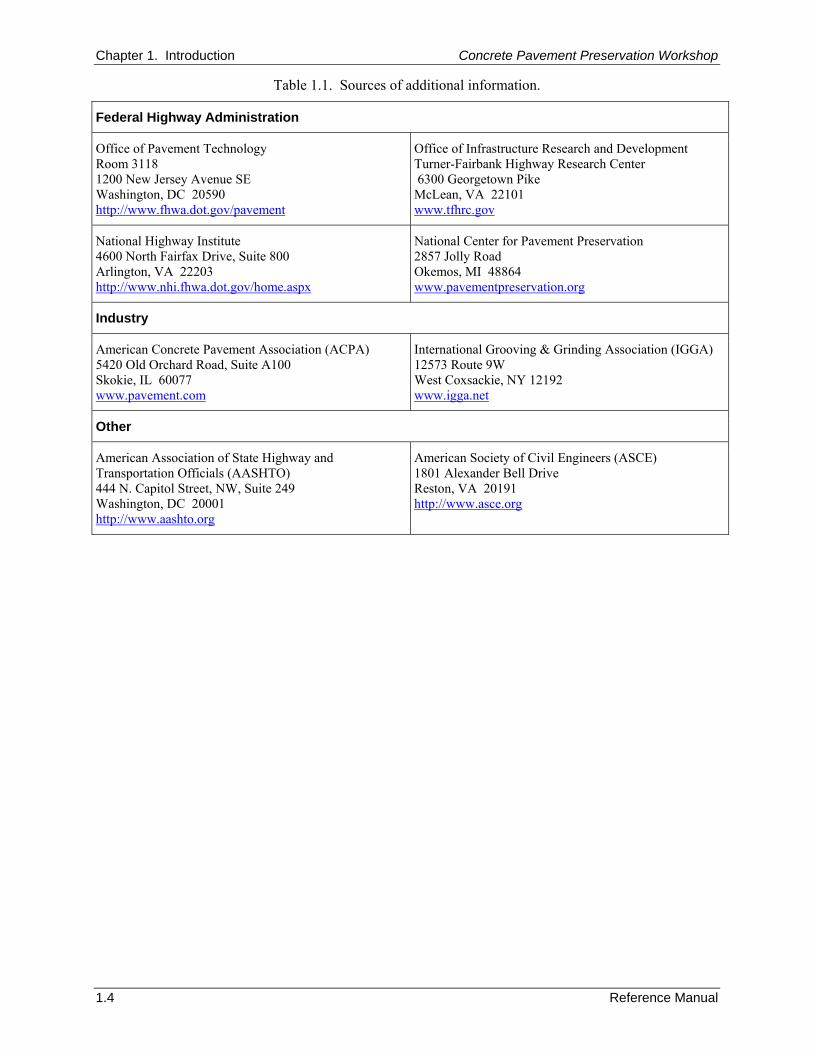
Copies of all visual aids shown by the instructors. The Reference Manual and the Participant Workbook are meant to be used together, both during the course presentation and afterwards, as technical resources. While the Reference Manual has been developed to include detailed technical information on the design and construction of concrete pavement preservation treatments, the course is not taught directly from this document. Those who follow the course presentation with the Participant Workbook will find a useful place to note key concepts discussed during class and to jot down their own ideas that are triggered by those discussions. 5. ADDITIONAL INFORMATION This Reference Manual presents a considerable amount of information on the design, construction, and selection of preservation treatments for concrete pavements. However, there are a number of topics that can not be given a complete treatment because of the scope of the document and overall space limitations. Numerous references are cited throughout the document to provide interested readers with additional (and more detailed) sources of information. Many of these references are available from the organizations listed in table 1-1.
Chapter 1. Introduction Concrete Pavement Preservation Workshop
1.4 Reference Manual
Table 1.1. Sources of additional information.
Federal Highway Administration
Office of Pavement Technology Room 3118 1200 New Jersey Avenue SE Washington, DC 20590 http://www.fhwa.dot.gov/pavement
Office of Infrastructure Research and Development Turner-Fairbank Highway Research Center 6300 Georgetown Pike McLean, VA 22101 www.tfhrc.gov
National Highway Institute 4600 North Fairfax Drive, Suite 800 Arlington, VA 22203 http://www.nhi.fhwa.dot.gov/home.aspx
National Center for Pavement Preservation 2857 Jolly Road Okemos, MI 48864 www.pavementpreservation.org
Industry
American Concrete Pavement Association (ACPA) 5420 Old Orchard Road, Suite A100 Skokie, IL 60077 www.pavement.com
International Grooving & Grinding Association (IGGA) 12573 Route 9W West Coxsackie, NY 12192 www.igga.net
Other
American Association of State Highway and Transportation Officials (AASHTO) 444 N. Capitol Street, NW, Suite 249 Washington, DC 20001 http://www.aashto.org
American Society of Civil Engineers (ASCE) 1801 Alexander Bell Drive Reston, VA 20191 http://www.asce.org
Concrete Pavement Preservation Workshop Chapter 2. Preservation Concepts
Reference Manual 2.1
CHAPTER 2. PREVENTIVE MAINTENANCE AND PAVEMENT PRESERVATION CONCEPTS
1. LEARNING OUTCOMES This chapter presents an overview of preventive maintenance and pavement preservation. Upon completion of this chapter, the participants will be able to accomplish the following:
1. Define pavement preservation and preventive maintenance.
2. Describe characteristics of suitable pavements for preventive maintenance.
3. Describe the importance of selecting the “right” treatment and placing it at the “right” time.
4. List some of the benefits of pavement preservation. 2. INTRODUCTION In recent years, the FHWA has been a strong proponent and supporter of the concept of cost effectively preserving the country’s roadway (pavement) network. This has helped to spur on a nationwide movement of pavement preservation and preventive maintenance programs. This is indeed a radically different approach to managing pavement networks than what has been used in the past. One of the big differences between past approaches and today’s emphasis on preservation and preventive maintenance is that preservation focuses on being “proactive” rather than “reactive.” The concept of adopting a proactive maintenance approach enables agencies to reduce the probability of costly, time consuming rehabilitation and reconstruction projects. One result is that the traveling public has benefited from improved safety and mobility, reduced congestion, and smoother, longer lasting pavements (Geiger 2005). This is the true goal of pavement preservation, a goal in which the FHWA, through its partnership with States, local agencies, industry organizations, and other interested stakeholders, is committed to achieve (Geiger 2005). As a primer to the remaining chapters in this manual, this chapter introduces many of the pavement preservation concepts currently being promoted by the FHWA. Specifically, this chapter introduces common pavement preservation-related definitions, discusses the importance and benefits of conducting preventive maintenance, and describes recent initiatives and State Department of Transportation (DOT) experiences. 3. DEFINITIONS During the evolution of pavement preservation concepts over the past decade, it has not been uncommon to hear questions such as the following:
What is pavement preservation?
What is the difference between “pavement preservation” and “preventive maintenance?”
How does “preventive maintenance” differ from “corrective maintenance?”
What characteristics make a treatment fit into the “preventive” category? In order to promote a uniform understanding among all agencies, a 2005 memorandum clarified the Federal Highway Administration’s pavement preservation-related definitions (Geiger 2005). The remainder of this “Definitions” section contains definitions taken verbatim from the 2005 memorandum “Pavement Preservation Definitions” (Geiger 2005).
Chapter 2. Preservation Concepts Concrete Pavement Preservation Workshop
2.2 Reference Manual
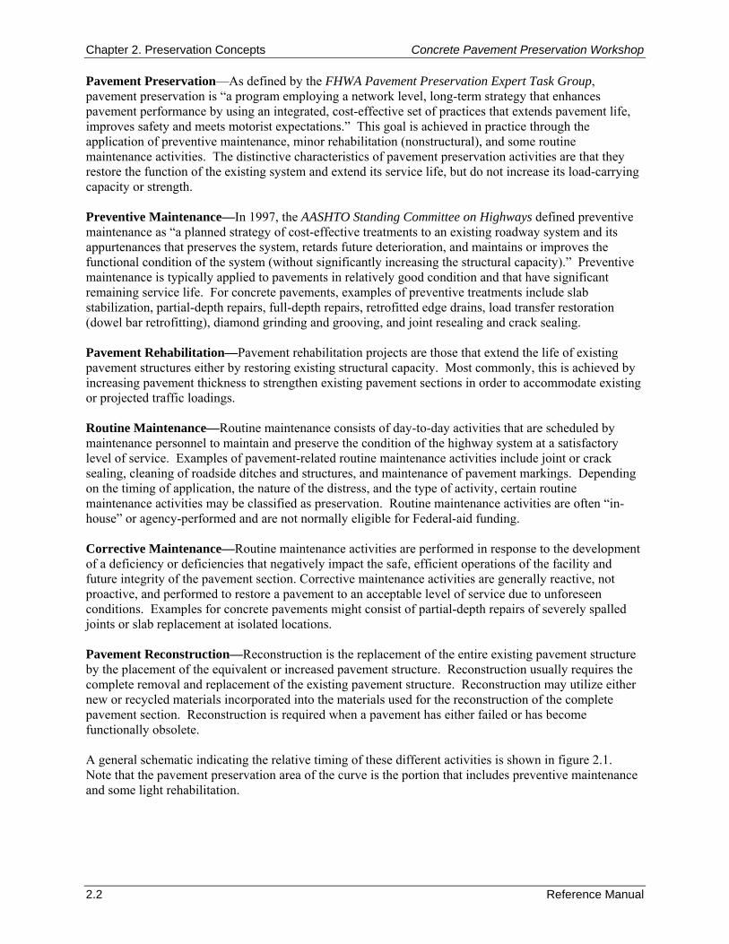
Pavement Preservation—As defined by the FHWA Pavement Preservation Expert Task Group, pavement preservation is “a program employing a network level, long-term strategy that enhances pavement performance by using an integrated, cost-effective set of practices that extends pavement life, improves safety and meets motorist expectations.” This goal is achieved in practice through the application of preventive maintenance, minor rehabilitation (nonstructural), and some routine maintenance activities. The distinctive characteristics of pavement preservation activities are that they restore the function of the existing system and extend its service life, but do not increase its load-carrying capacity or strength. Preventive Maintenance—In 1997, the AASHTO Standing Committee on Highways defined preventive maintenance as “a planned strategy of cost-effective treatments to an existing roadway system and its appurtenances that preserves the system, retards future deterioration, and maintains or improves the functional condition of the system (without significantly increasing the structural capacity).” Preventive maintenance is typically applied to pavements in relatively good condition and that have significant remaining service life. For concrete pavements, examples of preventive treatments include slab stabilization, partial-depth repairs, full-depth repairs, retrofitted edge drains, load transfer restoration (dowel bar retrofitting), diamond grinding and grooving, and joint resealing and crack sealing. Pavement Rehabilitation—Pavement rehabilitation projects are those that extend the life of existing pavement structures either by restoring existing structural capacity. Most commonly, this is achieved by increasing pavement thickness to strengthen existing pavement sections in order to accommodate existing or projected traffic loadings. Routine Maintenance—Routine maintenance consists of day-to-day activities that are scheduled by maintenance personnel to maintain and preserve the condition of the highway system at a satisfactory level of service. Examples of pavement-related routine maintenance activities include joint or crack sealing, cleaning of roadside ditches and structures, and maintenance of pavement markings. Depending on the timing of application, the nature of the distress, and the type of activity, certain routine maintenance activities may be classified as preservation. Routine maintenance activities are often “in-house” or agency-performed and are not normally eligible for Federal-aid funding. Corrective Maintenance—Routine maintenance activities are performed in response to the development of a deficiency or deficiencies that negatively impact the safe, efficient operations of the facility and future integrity of the pavement section. Corrective maintenance activities are generally reactive, not proactive, and performed to restore a pavement to an acceptable level of service due to unforeseen conditions. Examples for concrete pavements might consist of partial-depth repairs of severely spalled joints or slab replacement at isolated locations. Pavement Reconstruction—Reconstruction is the replacement of the entire existing pavement structure by the placement of the equivalent or increased pavement structure. Reconstruction usually requires the complete removal and replacement of the existing pavement structure. Reconstruction may utilize either new or recycled materials incorporated into the materials used for the reconstruction of the complete pavement section. Reconstruction is required when a pavement has either failed or has become functionally obsolete. A general schematic indicating the relative timing of these different activities is shown in figure 2.1. Note that the pavement preservation area of the curve is the portion that includes preventive maintenance and some light rehabilitation.
Concrete Pavement Preservation Workshop Chapter 2. Preservation Concepts
Reference Manual 2.3
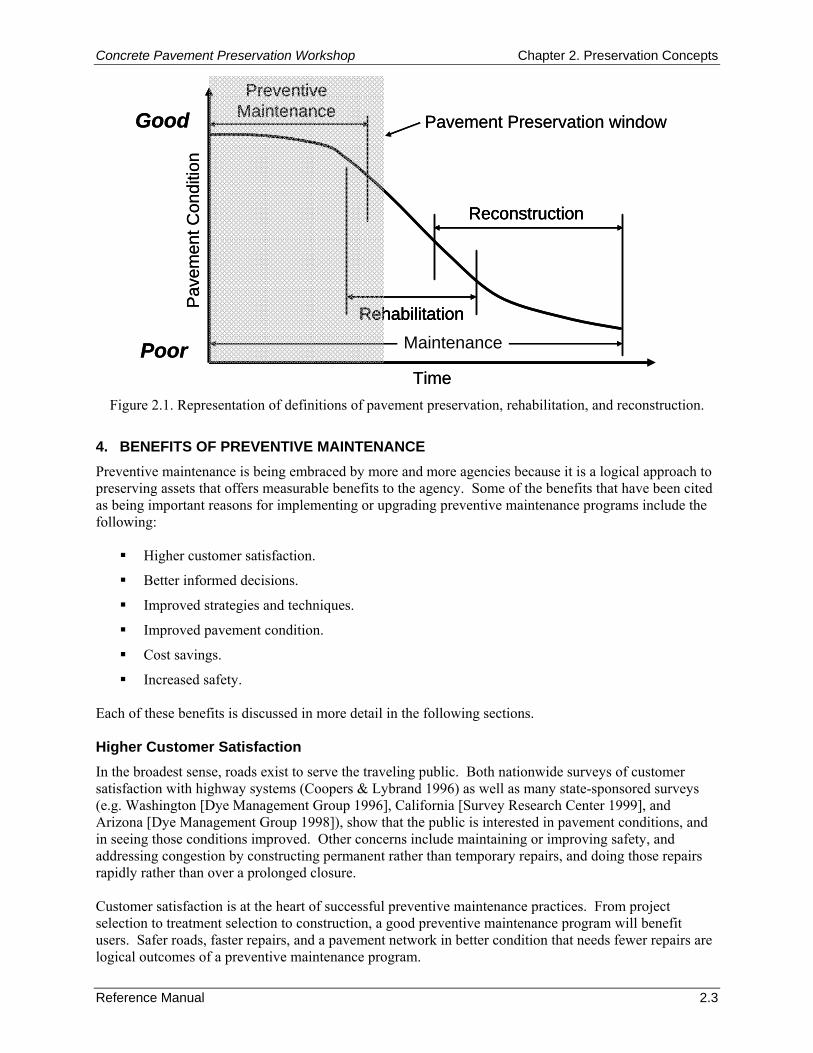
Figure 2.1. Representation of definitions of pavement preservation, rehabilitation, and reconstruction.
4. BENEFITS OF PREVENTIVE MAINTENANCE Preventive maintenance is being embraced by more and more agencies because it is a logical approach to preserving assets that offers measurable benefits to the agency. Some of the benefits that have been cited as being important reasons for implementing or upgrading preventive maintenance programs include the following:
Higher customer satisfaction.
Better informed decisions.
Improved strategies and techniques.
Improved pavement condition.
Cost savings.
Increased safety. Each of these benefits is discussed in more detail in the following sections. Higher Customer Satisfaction In the broadest sense, roads exist to serve the traveling public. Both nationwide surveys of customer satisfaction with highway systems (Coopers & Lybrand 1996) as well as many state-sponsored surveys (e.g. Washington [Dye Management Group 1996], California [Survey Research Center 1999], and Arizona [Dye Management Group 1998]), show that the public is interested in pavement conditions, and in seeing those conditions improved. Other concerns include maintaining or improving safety, and addressing congestion by constructing permanent rather than temporary repairs, and doing those repairs rapidly rather than over a prolonged closure. Customer satisfaction is at the heart of successful preventive maintenance practices. From project selection to treatment selection to construction, a good preventive maintenance program will benefit users. Safer roads, faster repairs, and a pavement network in better condition that needs fewer repairs are logical outcomes of a preventive maintenance program.
Pavement Preservation window
Pav
emen
t Con
ditio
n
Time
PreventiveMaintenance
Reconstruction
Good
Poor
RehabilitationMaintenance
Pavement Preservation window
Pav
emen
t Con
ditio
n
Time
PreventiveMaintenance
ReconstructionReconstruction
Good
Poor
RehabilitationRehabilitationMaintenance
Chapter 2. Preservation Concepts Concrete Pavement Preservation Workshop
2.4 Reference Manual
Better Informed Decisions Preventive maintenance programs rely on proper treatment selection and timing of the treatment to be successful. In order to select the right treatment for the right pavement at the right time, the following need to be known:
What is the structure and condition of the existing pavement?
What is the expected performance of the pavement?
How will different treatments affect this performance?
What other factors affect how the treatments will perform? The availability of and accessibility to information is an essential part of the process of managing a successful preventive maintenance program. All of the successful programs have exploited the information that is available from a pavement management system (PMS) to help in the decision-making process. For example, Caltrans uses condition survey data from their PMS to prioritize projects and differentiate among the candidates for rehabilitation, routine maintenance, and capital preventive maintenance (CAPM) (Caltrans 1996). They program their preventive maintenance treatments or “CAPM” projects in the same way as rehabilitation and other projects. This relationship is critical because Caltrans recognizes that the placement of preventive maintenance treatments is highly dependent upon timing. They must be programmed and applied before the condition of the pavement warrants a more serious repair. At the same time, Caltrans has developed appropriate treatments for the different types of expected pavement condition and identified optimum times to apply these treatments. Michigan DOT (MDOT) is another agency that has integrated its pavement management and preventive maintenance programs. In 1992, the DOT initiated the Michigan Preventive Maintenance Program (Galehouse 1998), with $8 million dedicated to highway preservation. During the period from 1992 through 1996, a total of $80 million was spent and almost 4,265 route km (2,650 route mi) of mainline pavement were treated. Using a module of their PMS to project long-term conditions and funding needs under different treatment scenarios, MDOT demonstrated that their preventive maintenance projects were more than six times as cost effective as rehabilitation or reconstruction. Improved Preventive Maintenance Strategies and Techniques One of the challenges to highway agencies and industry alike is to develop new and improved treatments to be used in preventive applications. Why are these needed? Conventional maintenance and rehabilitation treatments have evolved over the years to correct observed deficiencies, but may not be ideal for proactive applications in which life extension is expected. Preventive maintenance treatments must provide a better level of performance. Preventive maintenance treatments are designed to be applied while the pavement is still in good condition and are meant to help to maintain the pavement at a high level of service. Treated pavements are smoother, have improved friction characteristics, and should last longer between rehabilitation or reconstruction. To be effective, these applications often require the use of high quality materials and quality control may play a much larger role than with other types of treatments. As a result, many of today’s materials have been designed to provide the improved performance that users seek. While the initial treatment costs may be higher in some cases, the expected life of the treatment is going to be much greater than conventional applications. The net effect is that overall maintenance costs will be reduced. As part of a changing attitude toward maintenance, higher quality, more durable materials are being evaluated by many agencies, along with new or improved application methods. Innovation in the development of these improved materials and treatment strategies has come from industry, agencies, and researchers.
Concrete Pavement Preservation Workshop Chapter 2. Preservation Concepts
Reference Manual 2.5
Time
Good
Pav
emen
t Con
ditio
n
Poor
Preventive Maintenance Rehabilitation
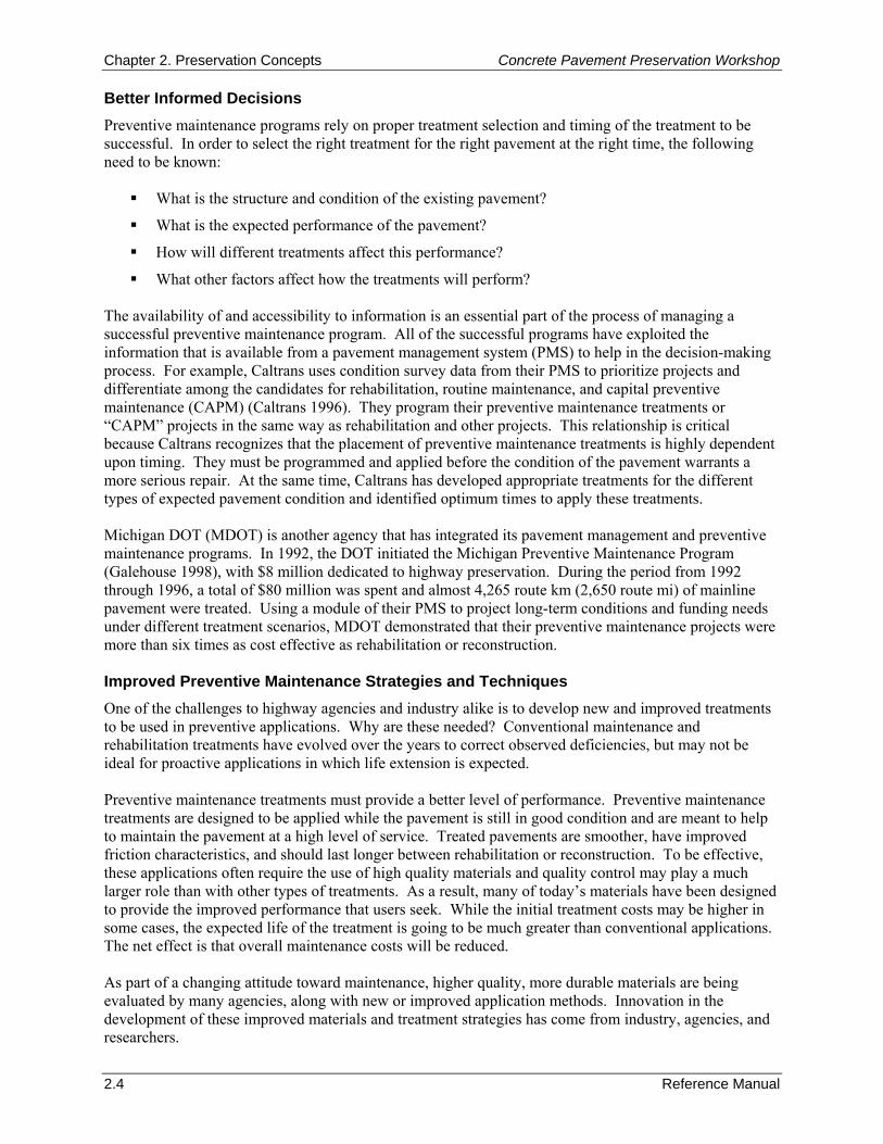
Improved Pavement Condition Agencies that have implemented preventive maintenance programs are not simply looking for a new way of doing the same old thing. The conventional approach most agencies take to manage their pavements consists of a combination of routine maintenance and rehabilitation. As previously described, routine maintenance is primarily a reactive process in which existing distresses are repaired; rehabilitation is typically programmed following the “worst first” principle, in which pavements are allowed to deteriorate until the worst one rises to the top of the capital projects list. In contrast, preventive maintenance is a proactive approach intended to preserve a pavement and extend its useful performance period or cycle. The difference between these two approaches is substantial and central to the preventive maintenance concept. If pavements in good condition are kept in good condition longer, delaying the need for rehabilitation and reconstruction, then an obvious benefit is overall improved conditions. This is illustrated in figure 2.2.
Figure 2.2. Illustration of typical effects of preventive maintenance and rehabilitation on pavement performance.
Cost Savings From an agency standpoint, probably the most sought after benefit of preventive maintenance is financial. Saving money through a policy of preventive maintenance is certainly an intended benefit, but one that has been hard to prove. Nonetheless, a number of agencies have reported or projected cost savings from preventive maintenance strategies. These savings are both in the form of less expensive treatments and pavements with extended service lives, and are often used as the most persuasive argument to shifting pavement preservation strategies. A reduction in user costs may also provide additional cost savings. These savings result from fewer delays, smoother roads (and lower vehicle operating costs), and enhanced safety (and thus lower crash-related costs). However, it must be noted that this analysis should not be reduced to the absurd level of applying frequent, very thin treatments; at some point the savings are offset by the disruption caused by more frequent treatment applications. The agencies that have been active in preventive maintenance report that even after a relatively short time they are beginning to see the financial benefits of their practices. Michigan ($700 million over 5 years) and California (a 4:1 to 6:1 benefit with preventive maintenance treatments) specifically are reporting
Chapter 2. Preservation Concepts Concrete Pavement Preservation Workshop
2.6 Reference Manual
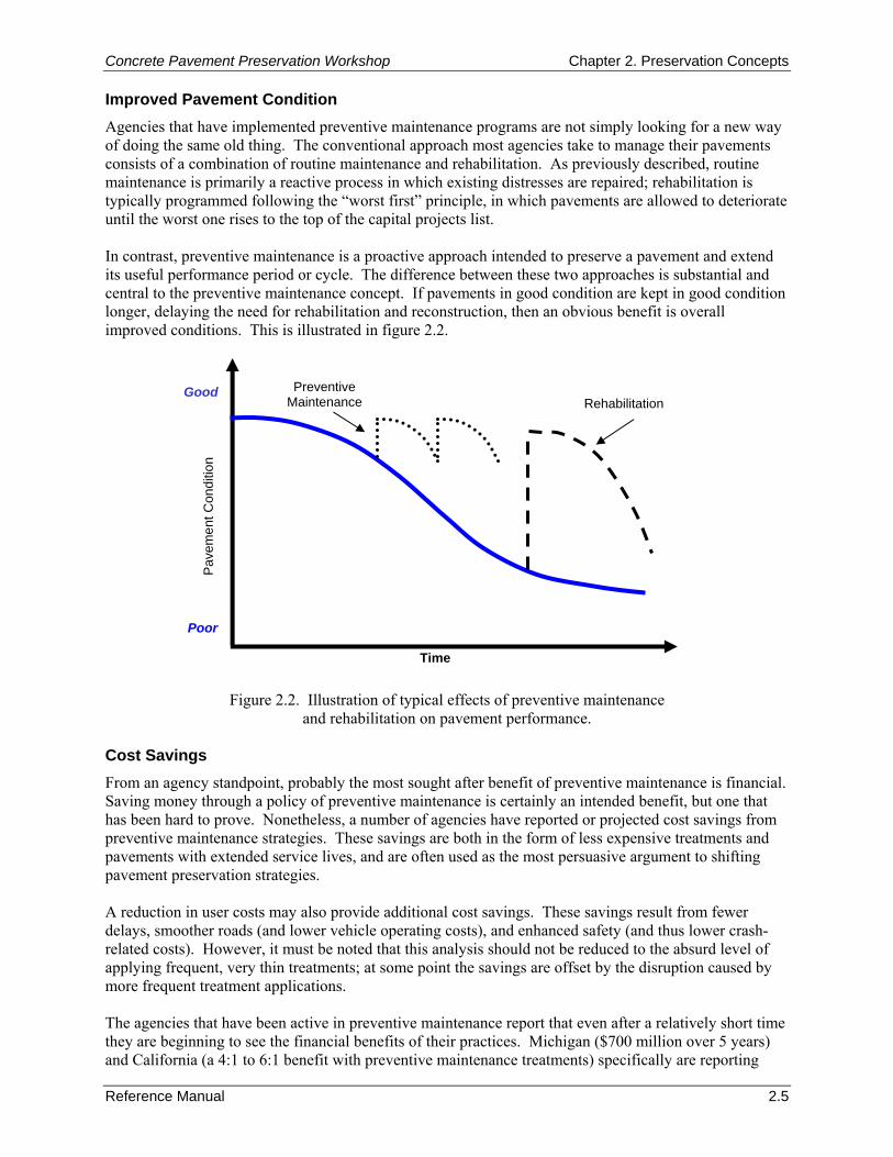
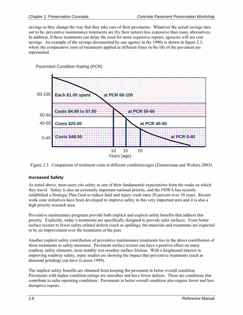
savings as they change the way that they take care of their pavements. Whatever the actual savings turn out to be, preventive maintenance treatments are (by their nature) less expensive than many alternatives. In addition, if these treatments can delay the need for more expensive repairs, agencies will see cost savings. An example of the savings documented by one agency in the 1990s is shown in figure 2.3, where the comparative costs of treatments applied at different times in the life of the pavement are represented.
Figure 2.3. Comparison of treatment costs at different conditions/ages (Zimmerman and Wolters 2003).
Increased Safety As noted above, most users cite safety as one of their fundamental expectations from the roads on which they travel. Safety is also an extremely important national priority, and the FHWA has recently established a Strategic Plan Goal to reduce fatal and injury crash rates 20 percent over 10 years. Recent work zone initiatives have been developed to improve safety in this very important area and it is also a high priority research area. Preventive maintenance programs provide both implicit and explicit safety benefits that address this priority. Explicitly, today’s treatments are specifically designed to provide safer surfaces. From better surface texture to fewer safety-related defects (such as spalling), the materials and treatments are expected to be an improvement over the treatments of the past. Another explicit safety contribution of preventive maintenance treatments lies in the direct contribution of those treatments to safety measures. Pavement surface texture can have a positive effect on many roadway safety elements, most notably wet-weather surface friction. With a heightened interest in improving roadway safety, many studies are showing the impact that preventive treatments (such as diamond grinding) can have (Larson 1999). The implicit safety benefits are obtained from keeping the pavement in better overall condition. Pavements with higher condition ratings are smoother and have fewer defects. These are conditions that contribute to safer operating conditions. Pavements in better overall condition also require fewer and less disruptive repairs.
Years (age)
Pavement Condition Rating (PCR)
10 15 20
0-40
40-50
50-60
60-100
Costs $4.80 to $7.00 at PCR 50-60
Costs $20.00 at PCR 40-50
Costs $48.00 at PCR 0-40
Each $1.00 spent at PCR 60-100

Concrete Pavement Preservation Workshop Chapter 2. Preservation Concepts
Reference Manual 2.7
None of these benefits stands alone. For any to be realized, the preventive maintenance treatment must be placed on a pavement that is a good candidate for preventive maintenance. The treatment must be properly designed, it must be properly constructed, and it must be properly maintained throughout its life. 5. RECENT INITIATIVES/STATE DOT EXPERIENCES Many State Highway Agencies (and local agencies as well) are moving forward with initiatives intended to improve their pavement preventive maintenance practices. These are identified as “best practices,” helping agencies to develop and sustain successful programs. These include the following, discussed in greater detail below:
Preservation Engineer.
Manuals of Practice.
Test Sections.
Research and Training.
Links Between Preventive Maintenance and Pavement Management. Preservation Engineer. Perhaps 10 years ago this position didn’t exist in any public agency; today at least half a dozen SHAs either have a person whose specific title is Preservation Engineer or who is solely responsible for the agency’s preservation program. These include California, North Carolina, Minnesota, New York, and Louisiana, among others. This designation provides several benefits. In addition to having an individual who can help to improve preventive maintenance practices throughout the agency, it also helps to substantially raise the profile of preservation and preventive maintenance and thereby ensure that the programs are sustainable beyond the short term. Manuals of Practice. A document that describes how to go about performing effective preventive maintenance can be a tremendous boon to an agency. These are often referred to as “manuals of practice” or “guides,” and typically include information about the various treatments in use locally, what they do, when they should be used, where they should be used, how they should be constructed, what benefits result from the proper use of the treatments, and so on. Examples include Caltrans’ Maintenance Technical Advisory Guide (Caltrans 2007), Nebraska’s Pavement Maintenance Manual (NDOR 2002), Ohio’s Pavement Preventive Maintenance Training Manual (ODOT 2001), and Colorado’s Preventive Maintenance Program Guidelines (CDOT 2004). By having a manual or guide, agencies can communicate what constitutes accepted practice, what works well locally, and provide resources for additional information. While they may vary in content and complexity, these documents are a significant improvement over the limited guidance that was previously available to help individual agencies. Test Sections. One of the barriers to more widespread acceptance of preventive maintenance is a lack of familiarity with what treatments are appropriate under what conditions. Previous nationwide studies (in the concrete area, the Strategic Highway Research Program’s [SHRP] SPS-4 studies) attempted to examine issues of maintenance effectiveness, but provided somewhat inconclusive results. By constructing test sections locally, using locally available or appropriate treatments perhaps applied to pavements of varying ages and stages of deterioration, an agency can develop a better understanding of what works well locally. Test sections can also supplement pavement performance information in a pavement management database to help improve treatment timing. Research and Training. Another barrier to widespread adoption of preventive maintenance practices is a lack of knowledge about what treatments work, where they work, and when they should be applied. Furthermore, sometimes personnel involved in treatment decision-making don’t have a full understanding of why they should be doing preventive maintenance.
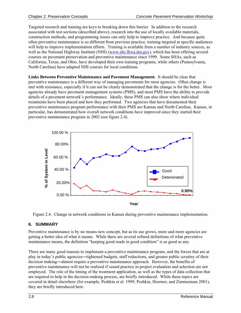
Chapter 2. Preservation Concepts Concrete Pavement Preservation Workshop
2.8 Reference Manual
Targeted research and training are keys to breaking down this barrier. In addition to the research associated with test sections (described above), research into the use of locally available materials, construction methods, and programming issues can only help to improve practice. And because quite often preventive maintenance is so different from previous practice, training targeted at specific audiences will help to improve implementation efforts. Training is available from a number of industry sources, as well as the National Highway Institute (NHI) (www.nhi.fhwa.dot.gov), which has been offering several courses on pavement preservation and preventive maintenance since 1999. Some SHAs, such as California, Texas, and Ohio, have developed their own training programs, while others (Pennsylvania, North Carolina) have adapted NHI courses for local conditions. Links Between Preventive Maintenance and Pavement Management. It should be clear that preventive maintenance is a different way of managing pavements for most agencies. Often change is met with resistance, especially if it can not be clearly demonstrated that the change is for the better. Most agencies already have pavement management systems (PMS), and most PMS have the ability to provide details of a pavement network’s performance. Ideally, these PMS can also show where individual treatments have been placed and how they performed. Two agencies that have documented their preventive maintenance program performance with their PMS are Kansas and North Carolina. Kansas, in particular, has demonstrated how overall network conditions have improved since they started their preventive maintenance program in 2002 (see figure 2.4).
Figure 2.4. Change in network conditions in Kansas during preventive maintenance implementation. 6. SUMMARY Preventive maintenance is by no means new concept, but as its use grows, more and more agencies are getting a better idea of what it means. While there are several refined definitions of what preventive maintenance means, the definition “keeping good roads in good condition” is as good as any. There are many good reasons to implement a preventive maintenance program, and the forces that are at play in today’s public agencies―tightened budgets, staff reductions, and greater public scrutiny of their decision making―almost require a preventive maintenance approach. However, the benefits of preventive maintenance will not be realized if sound practice in project evaluation and selection are not employed. The role of the timing of the treatment application, as well as the types of data collection that are required to help in the decision-making process, are briefly introduced. While these topics are covered in detail elsewhere (for example, Peshkin et al. 1999; Peshkin, Hoerner, and Zimmerman 2001), they are briefly introduced here.
0.90% 0.00 %
20.00%
60.00 %
80.00%
100.00 %
% o
f Sys
tem
in L
evel
40.00 %
0.90%
Good Deteriorated
Year
Concrete Pavement Preservation Workshop Chapter 2. Preservation Concepts
Reference Manual 2.9
7. REFERENCES Colorado Department of Transportation (CDOT). 2004. Preventive Maintenance Program Guidelines. Colorado Department of Transportation, Denver, CO.
Coopers & Lybrand and Opinion Research Corporation (ORC). 1996. National Highway User Survey.
California Department of Transportation (Caltrans). 1996. Pavement Maintenance & Rehabilitation. A Workshop for the California Transportation Commission. California Department of Transportation, Sacramento, CA.
California Department of Transportation (Caltrans). 2007. Maintenance Technical Advisory Guide, Volume II–Rigid Pavement Preservation. Draft Document. California Department of Transportation, Sacramento, CA.
Dye Management Group. 1996. Maintenance Management and Administration Evaluation. Washington State Department of Transportation, Seattle, WA.
Dye Management Group. 1998. Public Perceptions Report. Arizona Department of Transportation, Phoenix, AZ.
Geiger, D. R. 2005. Pavement Preservation Definitions. Technical Memorandum. Federal Highway Administration, Washington, DC.
Galehouse, L. 1998. “Innovative Concepts for Preventive Maintenance.” Transportation Research Record 1627. Transportation Research Board, Washington, DC.
Larson, R. M. 1999. Justification for Evaluation of Tire/Pavement Friction/Texture Effects on Total and Wet Weather Crash Rates. Final Draft. Federal Highway Administration, Washington, DC.
Nebraska Department of Roads (NDOR). 2002. Pavement Maintenance Manual. Nebraska Department of Roads, Lincoln, NE.
Ohio Department of Transportation (ODOT). 2001. Pavement Preventive Maintenance Program Guidelines. Ohio Department of Transportation, Columbus, OH.
Peshkin, D. G., K. D. Smith, K. A. Zimmerman, and D. N. Geoffroy. 1999. Pavement Preservation: The Preventive Maintenance Concept. Reference Manual, NHI Course 131054. National Highway Institute, Arlington, VA.
Peshkin, D. G., T. E. Hoerner, and K. A. Zimmerman. 2001. Pavement Preservation: Selecting Pavements for Preventive Maintenance. Participant’s Workbook, NHI Course 131058. National Highway Institute, Arlington, VA.
Survey Research Center. 1999. Survey of Licensed California Drivers Regarding Highway Maintenance Activities. Executive Summary. University Research Foundation, California State University, Chico, CA.
Zimmerman, K. A. and A. S. Wolters. 2003. Pavement Preservation: Integrating Pavement Preservation Practices and Pavement Management. Reference Manual, NHI Course 131104. National Highway Institute, Arlington, VA.

Chapter 2. Preservation Concepts Concrete Pavement Preservation Workshop
2.10 Reference Manual
NOTES
Concrete Pavement Preservation Workshop Chapter 3. Evaluation
Reference Manual 3.1
CHAPTER 3. CONCRETE PAVEMENT EVALUATION 1. LEARNING OUTCOMES This chapter presents a summary of the pavement evaluation process, including a description of the various pavement evaluation activities that are commonly conducted. Furthermore, this chapter describes how the results from the different pavement evaluation activities are brought together in an overall project evaluation. The results of the overall evaluation are used to assist in selecting cost-effective pavement preservation treatments. Upon completion of this chapter, the participants will be able to accomplish the following:
1. Describe the need for a thorough pavement evaluation and the uses of pavement evaluation data.
2. Name the common pavement evaluation components and what information is obtained from each.
3. Describe how pavement evaluation data are interpreted. 2. INTRODUCTION Prior to selecting any preservation or rehabilitation treatment for a given pavement, it is important to conduct a thorough pavement evaluation to determine the causes and extent of pavement deterioration. This requires a systematic data collection effort and an analysis of the structural and functional condition of the pavement as well as several other factors. The approach to pavement evaluation described in this chapter is consistent with that presented in the AASHTO Guide for Design of Pavement Structures (AASHTO 1993), as well as that presented in the Guide for Mechanistic-Empirical Design of New and Rehabilitated Pavement Structures (NCHRP 2004). The size of a project often dictates the amount of time and funds that can justifiably be spent on pavement evaluation. Additionally, critical projects on major highways and projects subjected to high traffic volumes require more comprehensive and thorough pavement evaluations than those on low-volume highways. This is not because data collection is less important on lower volume highways, but because the effects of premature failures on the higher volume highways are much more serious. Evaluating a pavement is similar to evaluating an automobile for repair. For example, prior to replacing a used car, the condition of the car, including its structural condition (e.g., motor, transmission, chassis), its functional condition (e.g., paint, interior, corrosion), and various individual components (e.g., speedometer, tires, windshield) should all be evaluated. The extent of deterioration can be assessed and either a cost-effective repair and preventive maintenance plan can be developed (combining the information from all of the different areas), or a decision made to replace the car. The consequences of neglecting to conduct such an evaluation could result in a very poor (and expensive) outcome. 3. DATA REQUIRED TO ACCOMPLISH A PAVEMENT EVALUATION A thorough pavement evaluation requires the collection of a substantial amount of data about and from the existing pavement. These data can be divided into the following major categories:
Pavement condition (e.g., distress, roughness, deflections).
Shoulder condition.
Pavement design (e.g., layer thicknesses, layer properties, structural characteristics, construction requirements).
Materials and soil properties.
Traffic volumes and loadings (current and projected).

Chapter 3. Evaluation Concrete Pavement Preservation Workshop
3.2 Reference Manual
Climatic conditions.
Drainage conditions.
Geometric factors.
Safety aspects (e.g., accidents, surface friction).
Miscellaneous factors (e.g., utilities, clearances). In many cases, the specific data to be collected under each of these general categories also depends upon the treatment alternatives being considered. For example, if grinding of a concrete pavement is to be considered, then the hardness of the aggregate and the faulting condition must be known. Similarly, if the addition of edge drains to a pavement project is being contemplated, the type and properties of the base and subbase materials must be determined. Table 3.1 provides a summary of suggested data collection items for various concrete treatment alternatives (AASHTO 1993). The data are classified as those that are “Definitely Needed,” “Desirable,” or “Not Normally Needed.” A thorough data collection effort serves the following important purposes in the overall pavement evaluation process:
It provides the qualitative information needed to determine the causes of pavement deterioration, and to develop appropriate alternatives for repairing the deterioration and preventing its recurrence.
It provides the quantitative information needed to make quantity estimates associated with different treatment alternatives, to assess the rate of deterioration of the pavement, and to perform life-cycle cost comparisons of competing treatment alternatives.
In pavement evaluation, the design engineer’s objective is to make the most efficient use of data collection resources so that sufficient information can be obtained to identify feasible alternatives and to develop cost-effective designs. 4. PAVEMENT EVALUATION OVERVIEW The activities included in a pavement evaluation will vary from project to project, depending on the type of project and its relative significance. Generally speaking, the overall pavement evaluation process can be broadly divided into the following general steps (Hoerner et al. 2001; NCHRP 2004):
1. Historical data collection and records review.
2. Initial site visit and assessment.
3. Field testing activities.
4. Laboratory materials characterization
5. Data analysis.
6. Final field evaluation report. A brief introduction to each of these pavement evaluation steps are presented in the following sections, with more detailed discussions on specific field and laboratory testing activities included later in the chapter.
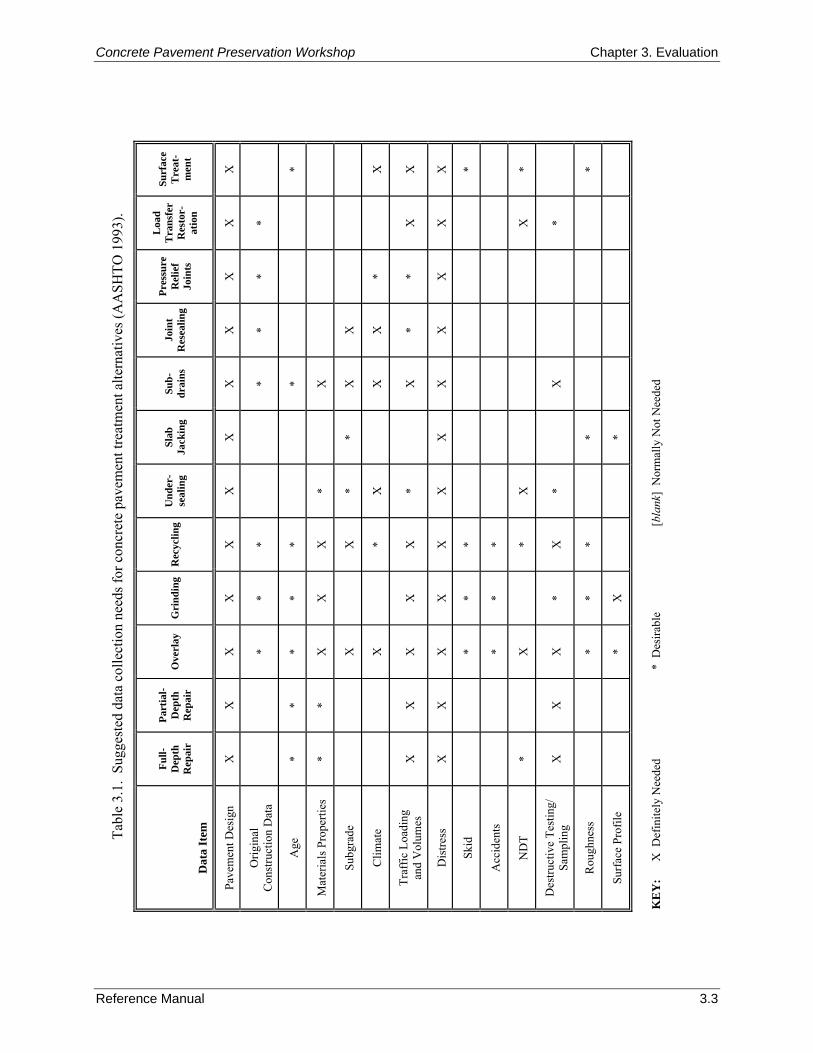
Tabl
e 3.
1. S
ugge
sted
dat
a co
llect
ion
need
s for
con
cret
e pa
vem
ent t
reat
men
t alte
rnat
ives
(AA
SHTO
199
3).
D
ata
Item
Full-
Dep
th
Rep
air
Part
ial-
Dep
th
Rep
air
Ove
rlay
G
rind
ing
Rec
yclin
gU
nder
-se
alin
g Sl
ab
Jack
ing
Sub-
drai
ns
Join
t R
esea
ling
Pres
sure
R
elie
f Jo
ints
Loa
d T
rans
fer
Res
tor-
atio
n
Surf
ace
Tre
at-
men
t
Pave
men
t Des
ign
X
X
X
X
X
X
X
X
X
X
X
X
Orig
inal
C
onst
ruct
ion
Dat
a
*
* *
* *
* *
Age
*
* *
* *
*
*
Mat
eria
ls P
rope
rties
*
* X
X
X
*
X
Subg
rade
X
X
* *
X
X
Clim
ate
X
*
X
X
X
*
X
Traf
fic L
oadi
ng
and
Vol
umes
X
X
X
X
X
*
X
*
* X
X
Dis
tress
X
X
X
X
X
X
X
X
X
X
X
X
Skid
*
* *
*
Acc
iden
ts
* *
*
ND
T *
X
* X
X
*
Des
truct
ive
Test
ing/
Sa
mpl
ing
X
X
X
* X
*
X
*
Rou
ghne
ss
* *
*
*
*
Surf
ace
Prof
ile
* X
*
KE
Y:
X D
efin
itely
Nee
ded
*
Des
irabl
e
[bla
nk]
Nor
mal
ly N
ot N
eede
d
Reference Manual 3.3
Concrete Pavement Preservation Workshop Chapter 3. Evaluation
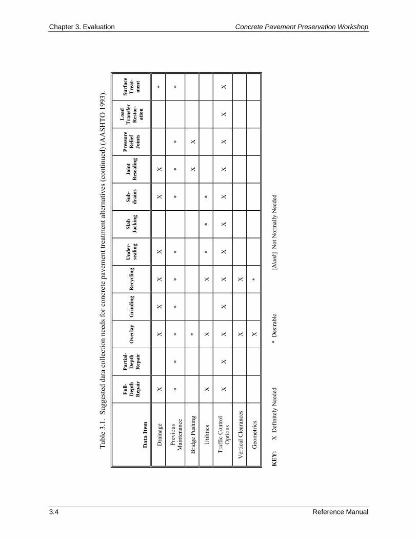
Tabl
e 3.
1. S
ugge
sted
dat
a co
llect
ion
need
s for
con
cret
e pa
vem
ent t
reat
men
t alte
rnat
ives
(con
tinue
d) (A
ASH
TO 1
993)
.
D
ata
Item
Full-
Dep
th
Rep
air
Part
ial-
Dep
th
Rep
air
Ove
rlay
G
rind
ing
Rec
yclin
gU
nder
-se
alin
g Sl
ab
Jack
ing
Sub-
drai
ns
Join
t R
esea
ling
Pres
sure
R
elie
f Jo
ints
Loa
d T
rans
fer
Res
tor-
atio
n
Surf
ace
Tre
at-
men
t
Dra
inag
e X
X
X
X
X
X
X
*
Prev
ious
M
aint
enan
ce
* *
* *
* *
*
* *
*
Brid
ge P
ushi
ng
*
X
X
Util
ities
X
X
X
*
* *
Traf
fic C
ontro
l O
ptio
ns
X
X
X
X
X
X
X
X
X
X
X
X
Ver
tical
Cle
aran
ces
X
X
Geo
met
rics
X
*
KE
Y:
X D
efin
itely
Nee
ded
*
Des
irabl
e
[bla
nk]
Not
Nor
mal
ly N
eede
d
3.4 Reference Manual
Chapter 3. Evaluation Concrete Pavement Preservation Workshop

Concrete Pavement Preservation Workshop Chapter 3. Evaluation
Reference Manual 3.5
Step 1: Historical Data Collection and Records Review The first step of the evaluation process is to review the available historical records that are associated with the project. This process involves the collection of data from office files and other historical records that provide basic information needed for conducting the pavement evaluation. The goal is to collect as much information on the existing pavement as possible, such as original design data, construction information, subgrade data, materials testing data, traffic data, performance data, and so on. Possible data sources for this data collection effort are:
Design reports.
Construction plans/specifications (new and rehabilitation).
Materials and soils properties from previous laboratory test programs and/or published reports.
Past pavement condition surveys, nondestructive testing and/or destructive sampling investigations.
Maintenance/repair histories.
Traffic measurements/forecasts.
Environmental/climate studies.
Pavement management system reports. The information gathered in this step can be used to divide the pavement into discrete sections with similar design and performance characteristics for the pavement evaluation. Step 2: Initial Site Visit and Assessment An initial site inspection is conducted to first gain a general knowledge of the performance of the pavement, and also to help determine the scope of the field testing activities to be conducted in step 3. As part of this activity, subjective information on distress, road roughness, surface friction, shoulder conditions, and moisture/drainage problems should be gathered. Unless high traffic volumes present a hazard, these data can be collected without any traffic control, through both “windshield” and observations from the roadside shoulder. In addition, an initial assessment of traffic control constraints, obstructions, right-of-way zones, presence of bridges and other structures, and general safety aspects should be made during this visit. Information obtained from this initial site visit and assessment will be used to formulate the type and extent of field testing activities performed under step 3. For example:
Distress observations may help identify the collection interval, the number of surveyors, and any additional measurement equipment that might be required.
Roughness data may dictate the need for a more rigorous measurement program to address any differential sag/swell problems.
Observations of moisture/drainage problems (e.g., pumping, corner breaks, standing water, and so on) may indicate the need for a more intensive deflection testing program or a more thorough investigation of subsurface drainage conditions.
Discussions with local design and maintenance engineers may also be beneficial to help gain a better understanding of the performance of the pavement.

Chapter 3. Evaluation Concrete Pavement Preservation Workshop
3.6 Reference Manual
Step 3: Field Testing Activities Under this step, detailed field measurements and testing are conducted to better characterize the performance of the pavement. The specific field testing activities are guided by the information obtained from the initial site visit and assessment, and may include:
Distress and drainage surveys—These surveys provide a visual indication of the structural condition of the existing pavement. The information gained from these surveys will have the greatest impact on the selection of the appropriate preservation or rehabilitation treatment, and consequently must be carefully performed.
Nondestructive deflection testing—Deflection testing may be conducted on certain projects to evaluate the overall structural condition of the pavement or to assess the joint load transfer capabilities. The scope of the deflection testing program should be established by the design engineer during or after the initial site visit.
Roughness and friction testing—This testing focuses on the functional performance of the pavement; that is, how well the pavement is meeting the rideability and safety needs of the traveling public.
Field sampling and testing—Field sampling and testing activities serve several purposes, such as the confirmation of layer materials and thicknesses and the retrieval of cores and subsurface samples for later laboratory testing. Most pavement preservation projects will not require field sampling or testing programs.
Specific details associated with each of these different types of field testing activities are discussed later in this chapter. Step 4: Laboratory Materials Characterization Laboratory testing is a more limited component of a thorough project evaluation, and is not required on every project. When included as part of the pavement evaluation process, laboratory testing may be conducted to confirm or clarify certain results from the distress surveys or the deflection testing program, to provide additional insight into the mechanisms of distress, or to provide additional information needed for the identification of feasible treatment alternatives. Examples of information that can be determined from laboratory testing include:
Concrete strength data.
Stiffness of concrete and of bound layers.
Petrographic testing and analysis of concrete layer.
Resilient modulus of the unbound layers and of the subgrade.
Density and gradation of underlying granular layers. Clearly, the above information is not needed for most pavement preservation projects. Step 5: Data Analysis For each field data collection activity, there is a corresponding element of analysis required. For the pavement condition data, such as distress, roughness, and friction, the data can be plotted along the project to illustrate varying conditions. If prepared in bar chart form, these profile plots can depict both the extent and severity at each measurement interval. Slab cracking, corner breaks, faulting, and spalling are candidate distresses that can be expressed in these types of illustrations; continuous plots of roughness or friction can also be displayed. In addition, areas of poor drainage or significant changes in topography (cut/fill sections) can also be overlaid on the strip charts.

Concrete Pavement Preservation Workshop Chapter 3. Evaluation
Reference Manual 3.7
Pavement condition information provides critical insight into a pavement’s structural and functional performance, and helps define when pavement preservation activities may or may not be appropriate. Table 3.2 presents examples of both general trigger and limit values for different pavement performance indicators. Trigger values define the point when pavement preservation may be appropriate, whereas limit values define the point at which the pavement is in need of major structural improvements. Many agencies have developed their own trigger and limit values for pavements within their jurisdiction. Nondestructive deflection testing on concrete pavements can be used in a number of ways, including development of pavement deflection profiles, backcalculation of layer properties, determination of load transfer capabilities, and evaluation of the potential for voids at slab corners. And, as discussed above, deflection data can be analyzed to help assess the structural capacity of the pavement. Step 6: Final Field Evaluation Report The final step in the evaluation process is the preparation of the field evaluation report, which summarizes the results of the data collection and analyses. In addition, any critical non-pavement factors, such as shoulder condition, ditches, right-of-way, curves, bridges, ramps, and traffic patterns, should be identified as part of the report. Ultimately, this information will be used in the identification and selection of appropriate treatments. 5. PAVEMENT DISTRESS AND DRAINAGE SURVEYS Section 4 provided an overview of the pavement evaluation process, and the remaining sections of this chapter describe the specific field testing components of the process, namely pavement distress and drainage surveys; deflection testing; roughness and surface friction testing; and material sampling and laboratory testing. As described previously, project-level pavement distress surveys are the first step in the overall pavement evaluation process, and serve as the cornerstone for evaluating the suitability of the pavement to receive preservation treatments. These surveys record visible distresses on the surface of the pavement, and are performed to:
Document pavement condition.
Identify types, quantities, and severities of distress observed distress.
Group areas of pavement exhibiting similar performance.
Gain insight into causes of deterioration (e.g., structural vs. functional).
Identify additional testing needs.
Identify potential treatment alternatives.
Identify repair areas and repair quantities. Pavement distress is any visible defect or form of deterioration on the surface of a pavement, and is the most basic measure of the performance of an existing pavement. In order to fully describe pavement distress, the following three factors must be considered:
Type—The type of distress is determined primarily by similar mechanisms of occurrence and appearance. By identifying the types of distress, a great deal of information can be inferred regarding the underlying causes of deterioration.
Severity—The severity of distress represents the criticality of the distress in terms of progression; more severe distresses will require more extreme rehabilitation measures.
Amount—The quantity of each type and severity level must be measured and expressed in convenient terms.
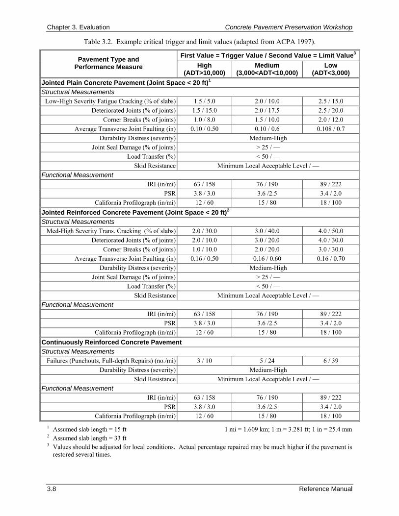
Chapter 3. Evaluation Concrete Pavement Preservation Workshop
3.8 Reference Manual
Table 3.2. Example critical trigger and limit values (adapted from ACPA 1997).
First Value = Trigger Value / Second Value = Limit Value3Pavement Type and
Performance Measure High (ADT>10,000)
Medium (3,000<ADT<10,000)
Low (ADT<3,000)
Jointed Plain Concrete Pavement (Joint Space < 20 ft)1 Structural Measurements
Low-High Severity Fatigue Cracking (% of slabs) 1.5 / 5.0 2.0 / 10.0 2.5 / 15.0 Deteriorated Joints (% of joints) 1.5 / 15.0 2.0 / 17.5 2.5 / 20.0
Corner Breaks (% of joints) 1.0 / 8.0 1.5 / 10.0 2.0 / 12.0 Average Transverse Joint Faulting (in) 0.10 / 0.50 0.10 / 0.6 0.108 / 0.7
Durability Distress (severity) Medium-High Joint Seal Damage (% of joints) > 25 / —
Load Transfer (%) < 50 / — Skid Resistance Minimum Local Acceptable Level / —
Functional Measurement IRI (in/mi) 63 / 158 76 / 190 89 / 222
PSR 3.8 / 3.0 3.6 /2.5 3.4 / 2.0 California Profilograph (in/mi) 12 / 60 15 / 80 18 / 100
Jointed Reinforced Concrete Pavement (Joint Space < 20 ft)2 Structural Measurements
Med-High Severity Trans. Cracking (% of slabs) 2.0 / 30.0 3.0 / 40.0 4.0 / 50.0 Deteriorated Joints (% of joints) 2.0 / 10.0 3.0 / 20.0 4.0 / 30.0
Corner Breaks (% of joints) 1.0 / 10.0 2.0 / 20.0 3.0 / 30.0 Average Transverse Joint Faulting (in) 0.16 / 0.50 0.16 / 0.60 0.16 / 0.70
Durability Distress (severity) Medium-High Joint Seal Damage (% of joints) > 25 / —
Load Transfer (%) < 50 / — Skid Resistance Minimum Local Acceptable Level / —
Functional Measurement IRI (in/mi) 63 / 158 76 / 190 89 / 222
PSR 3.8 / 3.0 3.6 /2.5 3.4 / 2.0 California Profilograph (in/mi) 12 / 60 15 / 80 18 / 100
Continuously Reinforced Concrete Pavement Structural Measurements
Failures (Punchouts, Full-depth Repairs) (no./mi) 3 / 10 5 / 24 6 / 39 Durability Distress (severity) Medium-High
Skid Resistance Minimum Local Acceptable Level / — Functional Measurement
IRI (in/mi) 63 / 158 76 / 190 89 / 222 PSR 3.8 / 3.0 3.6 /2.5 3.4 / 2.0
California Profilograph (in/mi) 12 / 60 15 / 80 18 / 100 1 Assumed slab length = 15 ft 1 mi = 1.609 km; 1 m = 3.281 ft; 1 in = 25.4 mm 2 Assumed slab length = 33 ft 3 Values should be adjusted for local conditions. Actual percentage repaired may be much higher if the pavement is
restored several times.
Concrete Pavement Preservation Workshop Chapter 3. Evaluation
Reference Manual 3.9
Because excess moisture in the pavement structure contributes to the development of so many pavement distresses, it is helpful during the distress survey to also conduct a drainage survey. In a drainage survey, visual signs of poor drainage are noted and can be coupled with information from materials sampling testing and nondestructive deflection testing to provide some insight into the overall drainability of the pavement structure. Unless moisture-related problems are recognized and corrected where possible, the effectiveness of any pavement preservation activity will be reduced. The remainder of this section presents many of the important details associated with conducting both distress and drainage surveys. The first section discusses the importance of using a distress identification manual to standardize the way distresses are interpreted by raters in the field. Next, separate sections are used to present the guidelines associated with conducting distress and drainage surveys, respectively. Finally, guidance is provided on how to interpret the collected distress and drainage data. Distress Survey Procedures To be consistent in how the distress type, severity, and amount are determined during a distress survey, distress measurement protocols need to be adopted by the agency conducting the surveys. In recent years, significant progress has been made in the standardization of distress survey procedures. Several procedures are available at the national level, and most state highway agencies have developed their own survey procedures to assess the condition of their pavement structures. In the FHWA’s long-term pavement performance (LTPP) program, a detailed distress survey procedure and standardized distress definitions are available (Miller and Bellinger 2003). This document describes the appearance of each distress type, depicts the associated severity levels (where defined), and describes the standard units in which the distress is measured. Figures and photographs of the distress type at various levels of severity are also provided to aid the surveyor in the distress identification process. Table 3.3 summarizes the distresses defined for concrete pavements in that manual, and also notes whether the distresses are primarily traffic related or climate/materials related. Because this manual was developed for the LTPP program, the manual is more research oriented, and consequently requires that the pavement distress data be collected in considerable detail and at high levels of precision. Another common pavement distress survey procedure is the pavement condition index (PCI) procedure developed by the Army Corps of Engineers (Shahin and Walther 1990). Extensive work went into the development of a numerical index value that is used to represent the pavement’s structural integrity and its surface operational condition based on the observed distress. The resulting index, the pavement condition index, ranges from 0 (failed pavement) to 100 (perfect pavement) and accounts for the types of distress, the severity of the distresses, and the amount or extent of the distresses; the associated effects of these factors are combined into a composite PCI value through established “weighting factors” so that it more accurately reflects the overall performance of the pavement (Shahin and Walther 1990). The PCI procedure is intended primarily for network-level pavement management purposes, not only in documenting the current condition of the pavement but also in developing prediction models to forecast future pavement condition (Shahin and Walther 1990). However, the methodology is sufficiently comprehensive and flexible enough that it can be used in project-level analyses. Guidelines for Conducting Manual Distress Surveys Although modern technology has made automated distress data collection a more feasible alternative at the network level, manual distress surveys are still preferred at the project level. A manual distress survey is a “walking” survey of the pavement in which the entire limits of the project are evaluated and all distresses are measured, recorded, and mapped. Manual distress surveys serve as a cornerstone in the documentation of pavement condition and in the development of feasible treatment alternatives.
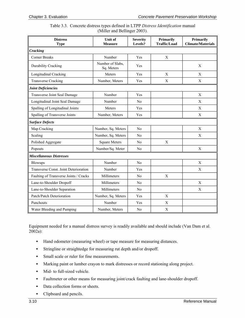
Chapter 3. Evaluation Concrete Pavement Preservation Workshop
3.10 Reference Manual
Table 3.3. Concrete distress types defined in LTPP Distress Identification manual (Miller and Bellinger 2003).
Distress Type
Unit of Measure
Severity Levels?
Primarily Traffic/Load
Primarily Climate/Materials
Cracking
Corner Breaks Number Yes X
Durability Cracking Number of Slabs, Sq. Meters Yes X
Longitudinal Cracking Meters Yes X X
Transverse Cracking Number, Meters Yes X X
Joint Deficiencies
Transverse Joint Seal Damage Number Yes X
Longitudinal Joint Seal Damage Number No X
Spalling of Longitudinal Joints Meters Yes X
Spalling of Transverse Joints Number, Meters Yes X
Surface Defects
Map Cracking Number, Sq. Meters No X
Scaling Number, Sq. Meters No X
Polished Aggregate Square Meters No X
Popouts Number/Sq. Meter No X
Miscellaneous Distresses
Blowups Number No X
Transverse Const. Joint Deterioration Number Yes X
Faulting of Transverse Joints / Cracks Millimeters No X
Lane-to-Shoulder Dropoff Millimeters No X
Lane-to-Shoulder Separation Millimeters No X
Patch/Patch Deterioration Number, Sq. Meters Yes X
Punchouts Number Yes X
Water Bleeding and Pumping Number, Meters No X
Equipment needed for a manual distress survey is readily available and should include (Van Dam et al. 2002a):
Hand odometer (measuring wheel) or tape measure for measuring distances.
Stringline or straightedge for measuring rut depth and/or dropoff.
Small scale or ruler for fine measurements.
Marking paint or lumber crayon to mark distresses or record stationing along project.
Mid- to full-sized vehicle.
Faultmeter or other means for measuring joint/crack faulting and lane-shoulder dropoff.
Data collection forms or sheets.
Clipboard and pencils.
Concrete Pavement Preservation Workshop Chapter 3. Evaluation
Reference Manual 3.11
Agency-approved distress-identification manual.
Camera or videotape for capturing representative distresses and conditions.
Hard hats and safety vests.
Traffic control provisions. Elements of a manual distress survey are described in the following sections. Pre-Survey Activities
Prior to any fieldwork, a preliminary records review should be conducted on the project. This should include information needed to assist in the conduct of the field surveys, such as general location information, general structural design information (pavement type, layer thicknesses, subgrade type, and so on), traffic information, and data from any previous distress surveys. Ideally, complete historical information on the project is desirable, although it may not always be available. Arrangements for the provision of traffic control should also be made prior to any fieldwork. Although some of the work can be performed from the shoulder, the pavement surveyor must be allowed on the pavement with the freedom to closely inspect the entire pavement. In addition, any sampling and testing activities that will be conducted will require complete access to the pavement. All traffic control arrangements should be scheduled as far in advance as possible and should adhere to the guidelines provided in the Manual on Uniform Traffic Control Devices (MUTCD) (FHWA 2003) or the agency’s governing requirements. Windshield Survey
As a first step in the pavement distress survey, a “windshield survey” should be conducted in which the entire project is driven in each lane in both directions at posted speed limits to get an overall “feel” or impression for how the pavement is performing. This is also the easiest way to get a measure of the overall rideability of the pavement. During these passes, any swells, depressions, or other sources of discomfort should be recorded and their location noted by milepost. Also, significant changes in overall pavement condition or performance over the length of the project should be noted. Detailed Distress Survey
A manual distress survey typically uses a two-person crew that walks along the shoulder of the entire project, noting all distresses and recording physical measurements (crack widths, faulting, drop-offs, and so on) as needed. In most cases, both travel lanes and shoulders are included in the survey. As previously described, if the project is on a busy roadway, traffic control should be provided for the safety of the survey crew. The data collection forms that are used to record the distresses can be easily developed to fit an agency’s objectives for distress surveys. These should be developed with the intended use of the data in mind in order to minimize future work. In addition, it is generally recommended that mapping of the project be conducted in order to help identify critical repair areas. An example field survey form used in the FHWA LTPP program is provided in figure 3.1 (Miller and Bellinger 2003). Some agencies have also used portable, hand-held computers to aid in the collection of distress data. Users can input distress quantities and amounts directly into the computer, which can then be downloaded for further evaluation. These can be convenient for reducing paperwork and are also effective in reducing transcription errors; some models also allow mapping of actual distresses. Field surveys using computers may proceed a little slower than surveys with data collection forms, but the time is made up in the processing of the data.
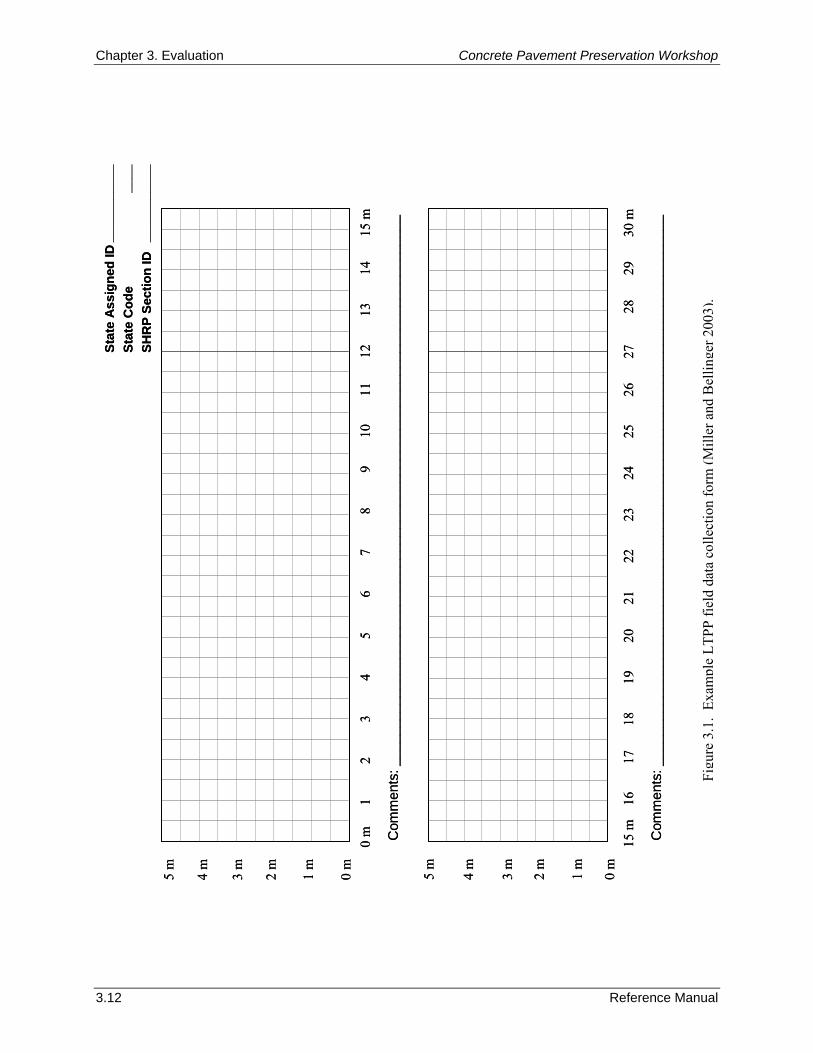
Chapter 3. Evaluation Concrete Pavement Preservation Workshop
3.12 Reference Manual
0 m
1
2
3
4
5
6
7
8
9
10
11
12
13
14
15
m
5 m
0 m
3 m
2 m
1 m
4 m
15 m
1
6
1
7
18
19
20
21
22
23
24
25
26
27
28
2
9
30
m
5 m
0 m
3 m
2 m
1 m
4 m
Com
men
ts: _
____
____
____
____
____
____
____
____
____
____
____
____
____
____
____
____
____
___
Com
men
ts: _
____
____
____
____
____
____
____
____
____
____
____
____
____
____
____
____
____
___
Stat
e A
ssig
ned
IDSt
ate
Cod
e SH
RP
Sect
ion
ID
____
____
___
____
__
____
____
_
0 m
1
2
3
4
5
6
7
8
9
10
11
12
13
14
15
m
5 m
0 m
3 m
2 m
1 m
4 m
15 m
1
6
1
7
18
19
20
21
22
23
24
25
26
27
28
2
9
30
m
5 m
0 m
3 m
2 m
1 m
4 m
Com
men
ts: _
____
____
____
____
____
____
____
____
____
____
____
____
____
____
____
____
____
___
Com
men
ts: _
____
____
____
____
____
____
____
____
____
____
____
____
____
____
____
____
____
___
Stat
e A
ssig
ned
IDSt
ate
Cod
e SH
RP
Sect
ion
ID
____
____
___
____
__
____
____
_
Figu
re 3
.1.
Exam
ple
LTPP
fiel
d da
ta c
olle
ctio
n fo
rm (M
iller
and
Bel
linge
r 200
3).
Concrete Pavement Preservation Workshop Chapter 3. Evaluation
Reference Manual 3.13
At the conclusion of the distress survey, it is recommended that a complete photo or video summary of the project be performed (Van Dam et al. 2002a). The purpose of this photo summary is to fully and completely document the condition of the pavement, as well as to record the prevailing foundation and drainage characteristics of the roadway. Guidelines for Conducting Pavement Drainage Surveys As part of a pavement distress survey, it is also important to assess the overall drainage conditions of the existing pavement. This is because poor drainage conditions have long been recognized as a major cause of distress in pavement structures, and unless moisture-related problems are identified and corrected where possible, the effectiveness of any preservation treatment will be reduced. Thus, the purposes of conducting a drainage survey are to:
Identify the presence of moisture-related distresses.
Document the prevailing drainage conditions of the pavement (e.g., cross slopes, cut/fill areas, depth and condition of ditches).
Assess the condition and effectiveness of edge drains (if present). The detection of possible drainage problems as evidenced from a drainage survey may suggest the need for an in-depth analysis of the drainability of the pavement structure. A computer program called DRIP (Drainage Requirements In Pavements) is available from FHWA that can assist in such an analysis (Mallela et al. 2002). The drainage survey is conducted at the same time as the manual distress survey. Particular attention should be given to the severity and extent of those distresses that are known to be moisture-related to help assess the degree to which excess moisture may be contributing to the pavement deterioration. The location of these distressed areas should be clearly noted. In addition, the following drainage-related items should be noted as part of the drainage survey:
Topography of the project. The overall topography and the approximate cut/fill depth should be noted along the length of the project to help determine if more distresses occur in certain cut or fill areas.
Transverse slopes of the shoulder and pavement. These should be evaluated to ensure that they are not ponding water or preventing the effective runoff of moisture from the surface. Typical recommendations for pavement surface drainage are a minimum 2 percent cross slope for mainline pavements and a 3 percent cross slope for shoulders (Anderson et al. 1998).
Condition of the ditches. The condition of the ditches (and the embankment material adjacent to the shoulder) should be noted along the length of the project to see if they are clear of standing water, debris, or vegetation that might otherwise impede the flow of water. The presence of cattails or willows growing in the ditch is a sign of excess moisture.
Geometrics of the ditches. The depth, width, and slope of the ditches should be noted along the length of the project to ensure that they facilitate the storage and movement of water. It is generally recommended that ditches be 1.2 m (4 ft) below the surface of the pavement, be at least 1 m (3 ft) wide, and have a minimum slope of 1 percent.
Condition of drainage outlets (if present). These should be assessed over the entire length of the project to ensure that they are clear of debris and set at the proper elevation above the ditchline. The overall condition of the outlets and headwall (if present) should also be assessed, and the presence or absence of outlet markers noted.
Condition of drainage inlets (if present). Many urban projects incorporate drainage inlets to remove surface water, and these should also be inspected over the length of the project. These should be free-flowing and clear of debris.
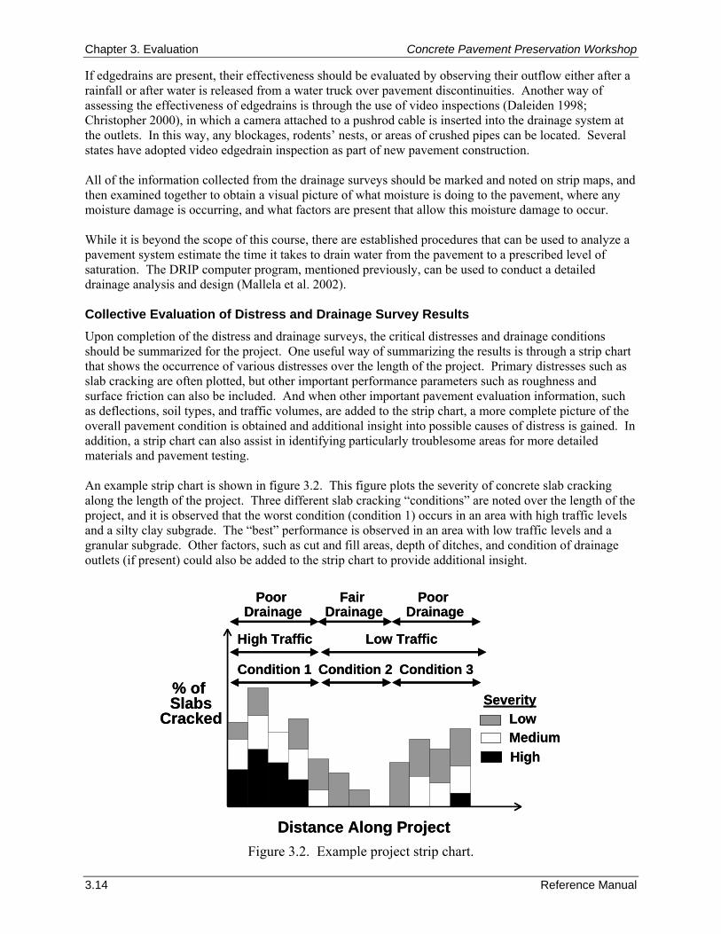
Chapter 3. Evaluation Concrete Pavement Preservation Workshop
3.14 Reference Manual
If edgedrains are present, their effectiveness should be evaluated by observing their outflow either after a rainfall or after water is released from a water truck over pavement discontinuities. Another way of assessing the effectiveness of edgedrains is through the use of video inspections (Daleiden 1998; Christopher 2000), in which a camera attached to a pushrod cable is inserted into the drainage system at the outlets. In this way, any blockages, rodents’ nests, or areas of crushed pipes can be located. Several states have adopted video edgedrain inspection as part of new pavement construction. All of the information collected from the drainage surveys should be marked and noted on strip maps, and then examined together to obtain a visual picture of what moisture is doing to the pavement, where any moisture damage is occurring, and what factors are present that allow this moisture damage to occur. While it is beyond the scope of this course, there are established procedures that can be used to analyze a pavement system estimate the time it takes to drain water from the pavement to a prescribed level of saturation. The DRIP computer program, mentioned previously, can be used to conduct a detailed drainage analysis and design (Mallela et al. 2002). Collective Evaluation of Distress and Drainage Survey Results Upon completion of the distress and drainage surveys, the critical distresses and drainage conditions should be summarized for the project. One useful way of summarizing the results is through a strip chart that shows the occurrence of various distresses over the length of the project. Primary distresses such as slab cracking are often plotted, but other important performance parameters such as roughness and surface friction can also be included. And when other important pavement evaluation information, such as deflections, soil types, and traffic volumes, are added to the strip chart, a more complete picture of the overall pavement condition is obtained and additional insight into possible causes of distress is gained. In addition, a strip chart can also assist in identifying particularly troublesome areas for more detailed materials and pavement testing. An example strip chart is shown in figure 3.2. This figure plots the severity of concrete slab cracking along the length of the project. Three different slab cracking “conditions” are noted over the length of the project, and it is observed that the worst condition (condition 1) occurs in an area with high traffic levels and a silty clay subgrade. The “best” performance is observed in an area with low traffic levels and a granular subgrade. Other factors, such as cut and fill areas, depth of ditches, and condition of drainage outlets (if present) could also be added to the strip chart to provide additional insight.
Figure 3.2. Example project strip chart.
Condition 1 Condition 2 Condition 3
Distance Along Project
% of Slabs
Cracked LowMediumHigh
Severity
High Traffic Low Traffic
Poor Drainage
Fair Drainage
Poor Drainage
Condition 1 Condition 2 Condition 3
Distance Along Project
% of Slabs
Cracked LowMediumHigh
Severity
High Traffic Low Traffic
Poor Drainage
Fair Drainage
Poor Drainage
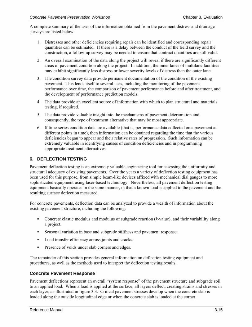
Concrete Pavement Preservation Workshop Chapter 3. Evaluation
Reference Manual 3.15
A complete summary of the uses of the information obtained from the pavement distress and drainage surveys are listed below:
1. Distresses and other deficiencies requiring repair can be identified and corresponding repair quantities can be estimated. If there is a delay between the conduct of the field survey and the construction, a follow-up survey may be needed to ensure that contract quantities are still valid.
2. An overall examination of the data along the project will reveal if there are significantly different areas of pavement condition along the project. In addition, the inner lanes of multilane facilities may exhibit significantly less distress or lower severity levels of distress than the outer lane.
3. The condition survey data provide permanent documentation of the condition of the existing pavement. This lends itself to several uses, including the monitoring of the pavement performance over time, the comparison of pavement performance before and after treatment, and the development of performance prediction models.
4. The data provide an excellent source of information with which to plan structural and materials testing, if required.
5. The data provide valuable insight into the mechanisms of pavement deterioration and, consequently, the type of treatment alternative that may be most appropriate.
6. If time-series condition data are available (that is, performance data collected on a pavement at different points in time), then information can be obtained regarding the time that the various deficiencies began to appear and their relative rates of progression. Such information can be extremely valuable in identifying causes of condition deficiencies and in programming appropriate treatment alternatives.
6. DEFLECTION TESTING Pavement deflection testing is an extremely valuable engineering tool for assessing the uniformity and structural adequacy of existing pavements. Over the years a variety of deflection testing equipment has been used for this purpose, from simple beam-like devices affixed with mechanical dial gauges to more sophisticated equipment using laser-based technology. Nevertheless, all pavement deflection testing equipment basically operates in the same manner, in that a known load is applied to the pavement and the resulting surface deflection measured. For concrete pavements, deflection data can be analyzed to provide a wealth of information about the existing pavement structure, including the following:
Concrete elastic modulus and modulus of subgrade reaction (k-value), and their variability along a project.
Seasonal variation in base and subgrade stiffness and pavement response.
Load transfer efficiency across joints and cracks.
Presence of voids under slab corners and edges. The remainder of this section provides general information on deflection testing equipment and procedures, as well as the methods used to interpret the deflection testing results. Concrete Pavement Response Pavement deflections represent an overall “system response” of the pavement structure and subgrade soil to an applied load. When a load is applied at the surface, all layers deflect, creating strains and stresses in each layer, as illustrated in figure 3.3. Critical pavement stresses develop when the concrete slab is loaded along the outside longitudinal edge or when the concrete slab is loaded at the corner.
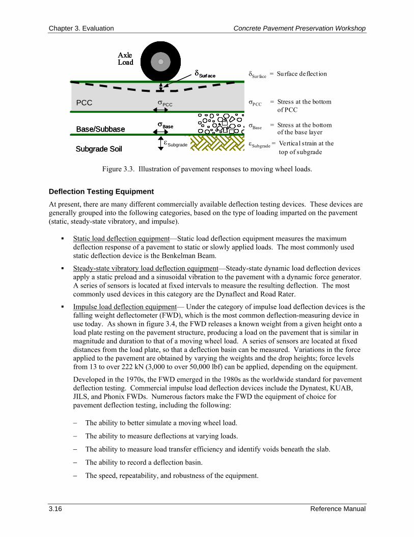
Chapter 3. Evaluation Concrete Pavement Preservation Workshop
3.16 Reference Manual
Subgrade Soil
Base/Subbase
PCC
εSubgrade
AxleLoad
δSurf ace
σPCC
σBase
δSurface = Surface deflect ion
σPCC = Stress at the bottomof PCC
σBase = Stress at the bottomof the base layer
εSubgrade = Vertical strain at thetop of subgradeSubgrade Soil
Base/Subbase
PCC
εSubgrade
AxleLoad
δSurf ace
σPCC
σBase
Subgrade Soil
Base/Subbase
PCC
εSubgrade
AxleLoad
δSurf ace
σPCC
σBase
δSurface = Surface deflect ion
σPCC = Stress at the bottomof PCC
σBase = Stress at the bottomof the base layer
εSubgrade = Vertical strain at thetop of subgrade
Figure 3.3. Illustration of pavement responses to moving wheel loads.
Deflection Testing Equipment At present, there are many different commercially available deflection testing devices. These devices are generally grouped into the following categories, based on the type of loading imparted on the pavement (static, steady-state vibratory, and impulse).
Static load deflection equipment—Static load deflection equipment measures the maximum deflection response of a pavement to static or slowly applied loads. The most commonly used static deflection device is the Benkelman Beam.
Steady-state vibratory load deflection equipment—Steady-state dynamic load deflection devices apply a static preload and a sinusoidal vibration to the pavement with a dynamic force generator. A series of sensors is located at fixed intervals to measure the resulting deflection. The most commonly used devices in this category are the Dynaflect and Road Rater.
Impulse load deflection equipment— Under the category of impulse load deflection devices is the falling weight deflectometer (FWD), which is the most common deflection-measuring device in use today. As shown in figure 3.4, the FWD releases a known weight from a given height onto a load plate resting on the pavement structure, producing a load on the pavement that is similar in magnitude and duration to that of a moving wheel load. A series of sensors are located at fixed distances from the load plate, so that a deflection basin can be measured. Variations in the force applied to the pavement are obtained by varying the weights and the drop heights; force levels from 13 to over 222 kN (3,000 to over 50,000 lbf) can be applied, depending on the equipment.
Developed in the 1970s, the FWD emerged in the 1980s as the worldwide standard for pavement deflection testing. Commercial impulse load deflection devices include the Dynatest, KUAB, JILS, and Phonix FWDs. Numerous factors make the FWD the equipment of choice for pavement deflection testing, including the following: − The ability to better simulate a moving wheel load.
− The ability to measure deflections at varying loads.
− The ability to measure load transfer efficiency and identify voids beneath the slab.
− The ability to record a deflection basin.
− The speed, repeatability, and robustness of the equipment.
Concrete Pavement Preservation Workshop Chapter 3. Evaluation
Reference Manual 3.17
Figure 3.4. Schematic of FWD device.
In the last decade, considerable work has been conducted on the development of deflection-measuring equipment capable of collecting continuous deflection data along the length of a project. Continuous deflection profiles provide the following advantages over discrete deflection measurements:
The entire length of the pavement project can be investigated. Thus, there is no danger of missing critical sections and no uncertainty about a test section being representative of the entire pavement system.
The spatial variability in deflections due to pavement features such as joints, cracks, patches, and changing constructed or subgrade conditions are identified.
More efficient testing and measurement operations, as there is no time lost stopping and starting. Currently, two such devices are under development, the Rolling Dynamic Deflectometer (RDD) and the Rolling Wheel Deflectometer (RWD), with each still in the prototype stage. More information on these devices is provided by Bay and Stokoe (2000) and by Grogg and Hall (2004). Factors That Influence Measured Deflections There are a number of factors that affect the magnitude of measured pavement deflections, which makes the interpretation of deflection results difficult. To the extent possible, direct consideration of these factors should be an integral part of the deflection testing process so that the resultant deflection data are meaningful and representative of actual conditions. The major factors that affect pavement deflections may be grouped into categories of pavement structure (type and thickness), pavement loading (load magnitude and type of loading), and climate (temperature and seasonal effects). Each of these is discussed in the following sections. Pavement Structure
As previously described, the deflection of a pavement represents an overall system response of the surface, base, subbase, and subgrade. Thus, the properties of the surface layer (thickness and stiffness) and of the supporting layers (thickness and stiffness) all affect the magnitude of the measured deflections. Generally speaking, “weaker” or “thinner” systems will deflect more than “stronger” or “thicker” systems under the same load, with the exact shape of the deflection basin related to the stiffness of the individual paving layers. As a general rule, pavements exhibiting greater deflections typically have shorter service lives. Many other pavement-related factors can affect deflections, including the following:
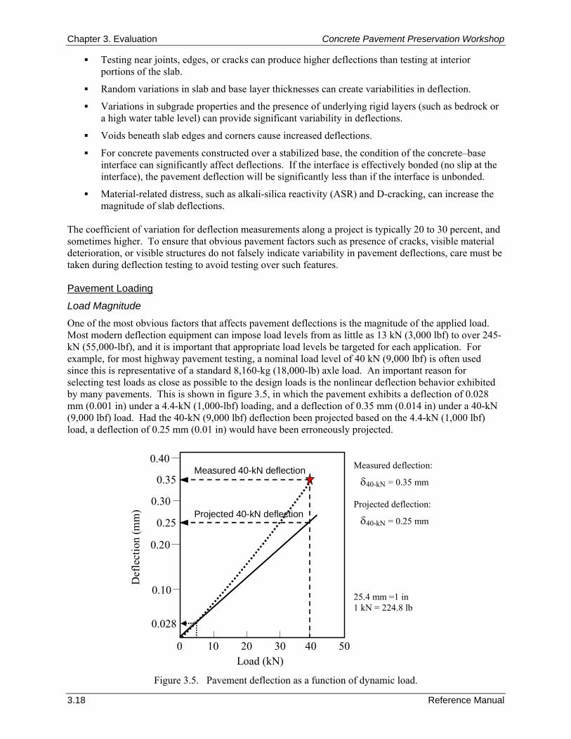
Chapter 3. Evaluation Concrete Pavement Preservation Workshop
3.18 Reference Manual
0 10 20 30 40 50
0.028
0.10
0.20
Measured 40-kN deflection
Load (kN)
Def
lect
ion
(mm
)
0.40
0.30
0.35
0.25Projected 40-kN deflection
Measured deflection:
δ40-kN = 0.35 mm Projected deflection:
δ40-kN = 0.25 mm 25.4 mm =1 in 1 kN = 224.8 lb
Testing near joints, edges, or cracks can produce higher deflections than testing at interior portions of the slab.
Random variations in slab and base layer thicknesses can create variabilities in deflection.
Variations in subgrade properties and the presence of underlying rigid layers (such as bedrock or a high water table level) can provide significant variability in deflections.
Voids beneath slab edges and corners cause increased deflections.
For concrete pavements constructed over a stabilized base, the condition of the concrete–base interface can significantly affect deflections. If the interface is effectively bonded (no slip at the interface), the pavement deflection will be significantly less than if the interface is unbonded.
Material-related distress, such as alkali-silica reactivity (ASR) and D-cracking, can increase the magnitude of slab deflections.
The coefficient of variation for deflection measurements along a project is typically 20 to 30 percent, and sometimes higher. To ensure that obvious pavement factors such as presence of cracks, visible material deterioration, or visible structures do not falsely indicate variability in pavement deflections, care must be taken during deflection testing to avoid testing over such features. Pavement Loading
Load Magnitude
One of the most obvious factors that affects pavement deflections is the magnitude of the applied load. Most modern deflection equipment can impose load levels from as little as 13 kN (3,000 lbf) to over 245-kN (55,000-lbf), and it is important that appropriate load levels be targeted for each application. For example, for most highway pavement testing, a nominal load level of 40 kN (9,000 lbf) is often used since this is representative of a standard 8,160-kg (18,000-lb) axle load. An important reason for selecting test loads as close as possible to the design loads is the nonlinear deflection behavior exhibited by many pavements. This is shown in figure 3.5, in which the pavement exhibits a deflection of 0.028 mm (0.001 in) under a 4.4-kN (1,000-lbf) loading, and a deflection of 0.35 mm (0.014 in) under a 40-kN (9,000 lbf) load. Had the 40-kN (9,000 lbf) deflection been projected based on the 4.4-kN (1,000 lbf) load, a deflection of 0.25 mm (0.01 in) would have been erroneously projected.
Figure 3.5. Pavement deflection as a function of dynamic load.
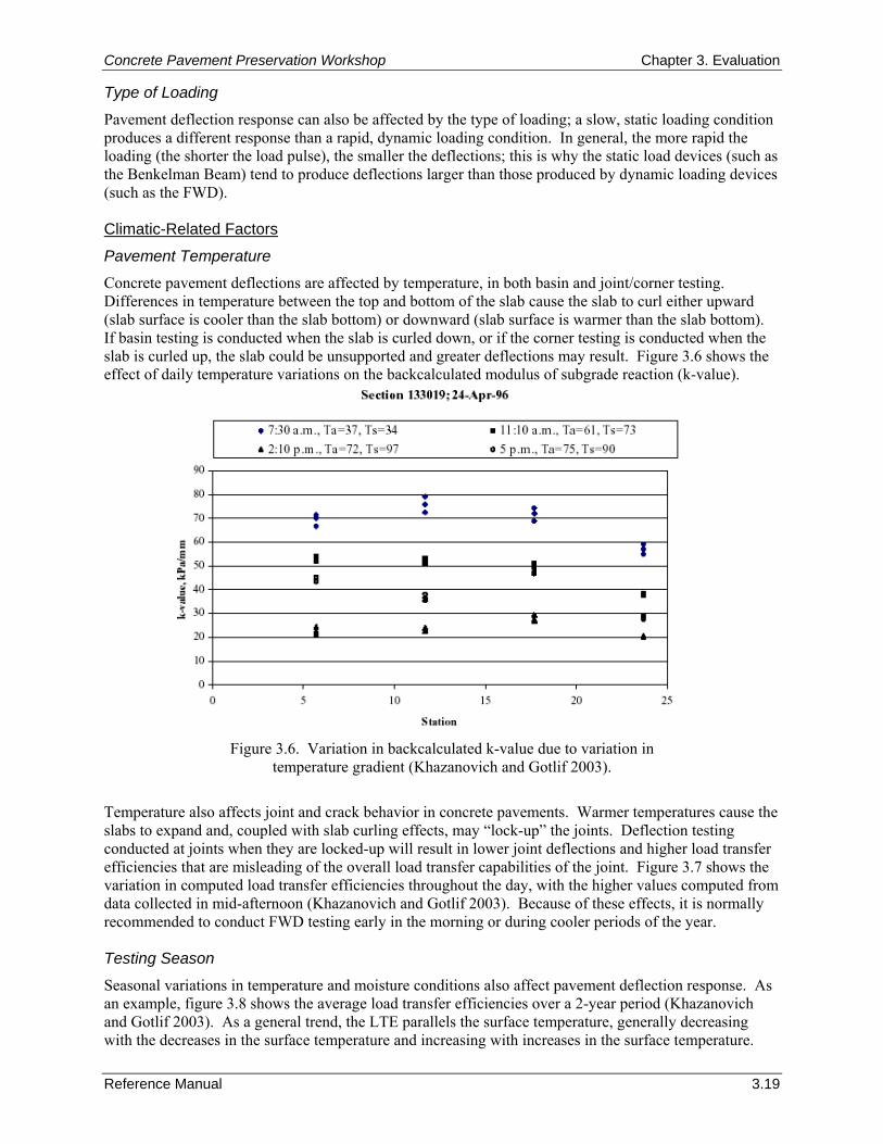
Concrete Pavement Preservation Workshop Chapter 3. Evaluation
Reference Manual 3.19
Type of Loading
Pavement deflection response can also be affected by the type of loading; a slow, static loading condition produces a different response than a rapid, dynamic loading condition. In general, the more rapid the loading (the shorter the load pulse), the smaller the deflections; this is why the static load devices (such as the Benkelman Beam) tend to produce deflections larger than those produced by dynamic loading devices (such as the FWD). Climatic-Related Factors
Pavement Temperature
Concrete pavement deflections are affected by temperature, in both basin and joint/corner testing. Differences in temperature between the top and bottom of the slab cause the slab to curl either upward (slab surface is cooler than the slab bottom) or downward (slab surface is warmer than the slab bottom). If basin testing is conducted when the slab is curled down, or if the corner testing is conducted when the slab is curled up, the slab could be unsupported and greater deflections may result. Figure 3.6 shows the effect of daily temperature variations on the backcalculated modulus of subgrade reaction (k-value).
Figure 3.6. Variation in backcalculated k-value due to variation in temperature gradient (Khazanovich and Gotlif 2003).
Temperature also affects joint and crack behavior in concrete pavements. Warmer temperatures cause the slabs to expand and, coupled with slab curling effects, may “lock-up” the joints. Deflection testing conducted at joints when they are locked-up will result in lower joint deflections and higher load transfer efficiencies that are misleading of the overall load transfer capabilities of the joint. Figure 3.7 shows the variation in computed load transfer efficiencies throughout the day, with the higher values computed from data collected in mid-afternoon (Khazanovich and Gotlif 2003). Because of these effects, it is normally recommended to conduct FWD testing early in the morning or during cooler periods of the year. Testing Season
Seasonal variations in temperature and moisture conditions also affect pavement deflection response. As an example, figure 3.8 shows the average load transfer efficiencies over a 2-year period (Khazanovich and Gotlif 2003). As a general trend, the LTE parallels the surface temperature, generally decreasing with the decreases in the surface temperature and increasing with increases in the surface temperature.
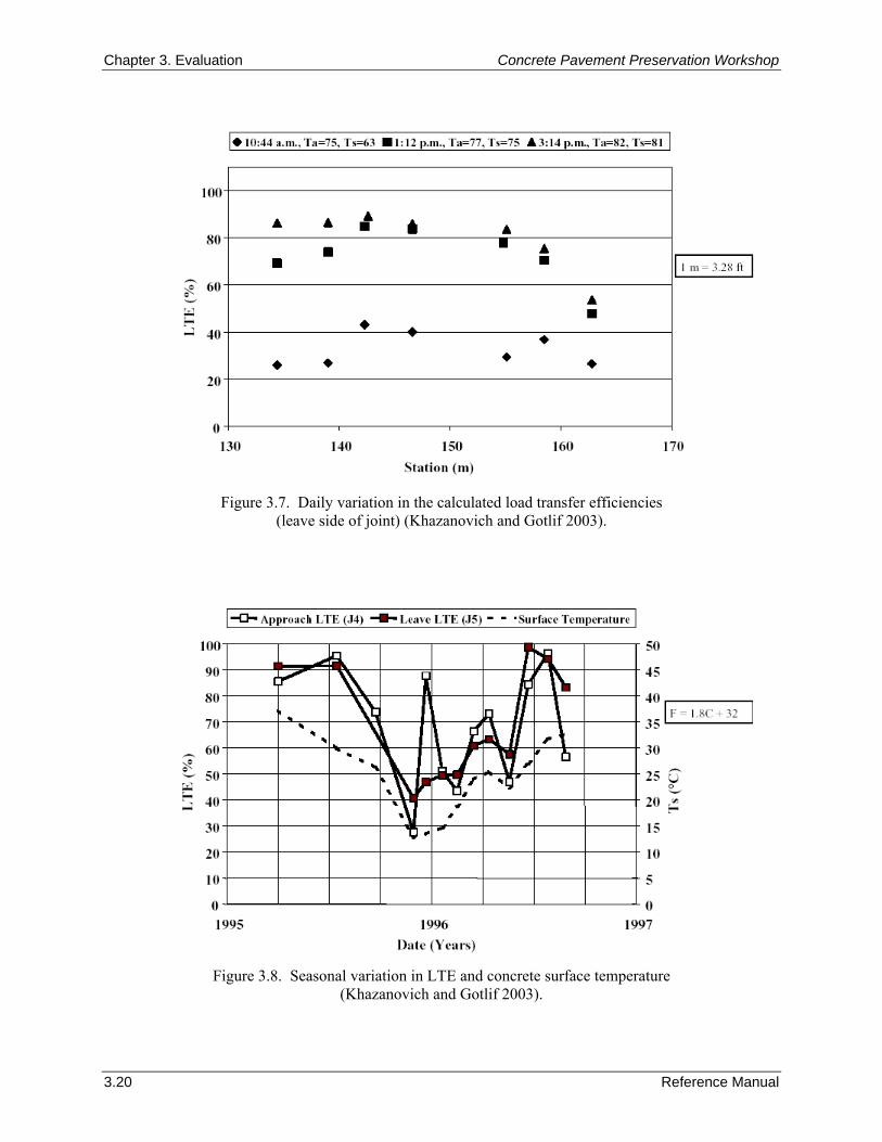
Chapter 3. Evaluation Concrete Pavement Preservation Workshop
3.20 Reference Manual
Figure 3.7. Daily variation in the calculated load transfer efficiencies (leave side of joint) (Khazanovich and Gotlif 2003).
Figure 3.8. Seasonal variation in LTE and concrete surface temperature (Khazanovich and Gotlif 2003).
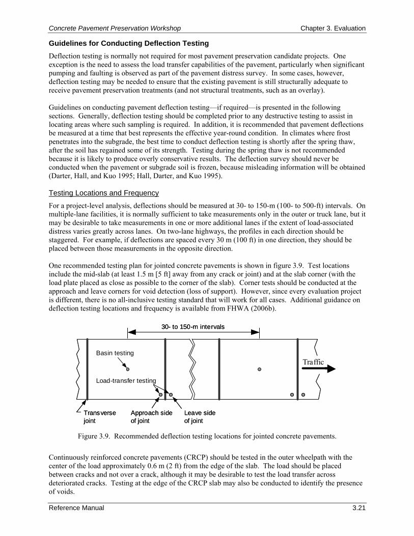
Concrete Pavement Preservation Workshop Chapter 3. Evaluation
Reference Manual 3.21
Guidelines for Conducting Deflection Testing Deflection testing is normally not required for most pavement preservation candidate projects. One exception is the need to assess the load transfer capabilities of the pavement, particularly when significant pumping and faulting is observed as part of the pavement distress survey. In some cases, however, deflection testing may be needed to ensure that the existing pavement is still structurally adequate to receive pavement preservation treatments (and not structural treatments, such as an overlay). Guidelines on conducting pavement deflection testing—if required—is presented in the following sections. Generally, deflection testing should be completed prior to any destructive testing to assist in locating areas where such sampling is required. In addition, it is recommended that pavement deflections be measured at a time that best represents the effective year-round condition. In climates where frost penetrates into the subgrade, the best time to conduct deflection testing is shortly after the spring thaw, after the soil has regained some of its strength. Testing during the spring thaw is not recommended because it is likely to produce overly conservative results. The deflection survey should never be conducted when the pavement or subgrade soil is frozen, because misleading information will be obtained (Darter, Hall, and Kuo 1995; Hall, Darter, and Kuo 1995). Testing Locations and Frequency
For a project-level analysis, deflections should be measured at 30- to 150-m (100- to 500-ft) intervals. On multiple-lane facilities, it is normally sufficient to take measurements only in the outer or truck lane, but it may be desirable to take measurements in one or more additional lanes if the extent of load-associated distress varies greatly across lanes. On two-lane highways, the profiles in each direction should be staggered. For example, if deflections are spaced every 30 m (100 ft) in one direction, they should be placed between those measurements in the opposite direction. One recommended testing plan for jointed concrete pavements is shown in figure 3.9. Test locations include the mid-slab (at least 1.5 m [5 ft] away from any crack or joint) and at the slab corner (with the load plate placed as close as possible to the corner of the slab). Corner tests should be conducted at the approach and leave corners for void detection (loss of support). However, since every evaluation project is different, there is no all-inclusive testing standard that will work for all cases. Additional guidance on deflection testing locations and frequency is available from FHWA (2006b).
Basin testing
Load-transfer testing
30- to 150-m intervals
Approach sideof joint
Leave sideof joint
Transversejoint
TrafficBasin testing
Load-transfer testing
30- to 150-m intervals
Approach sideof joint
Leave sideof joint
Transversejoint
Traffic
Figure 3.9. Recommended deflection testing locations for jointed concrete pavements.
Continuously reinforced concrete pavements (CRCP) should be tested in the outer wheelpath with the center of the load approximately 0.6 m (2 ft) from the edge of the slab. The load should be placed between cracks and not over a crack, although it may be desirable to test the load transfer across deteriorated cracks. Testing at the edge of the CRCP slab may also be conducted to identify the presence of voids.
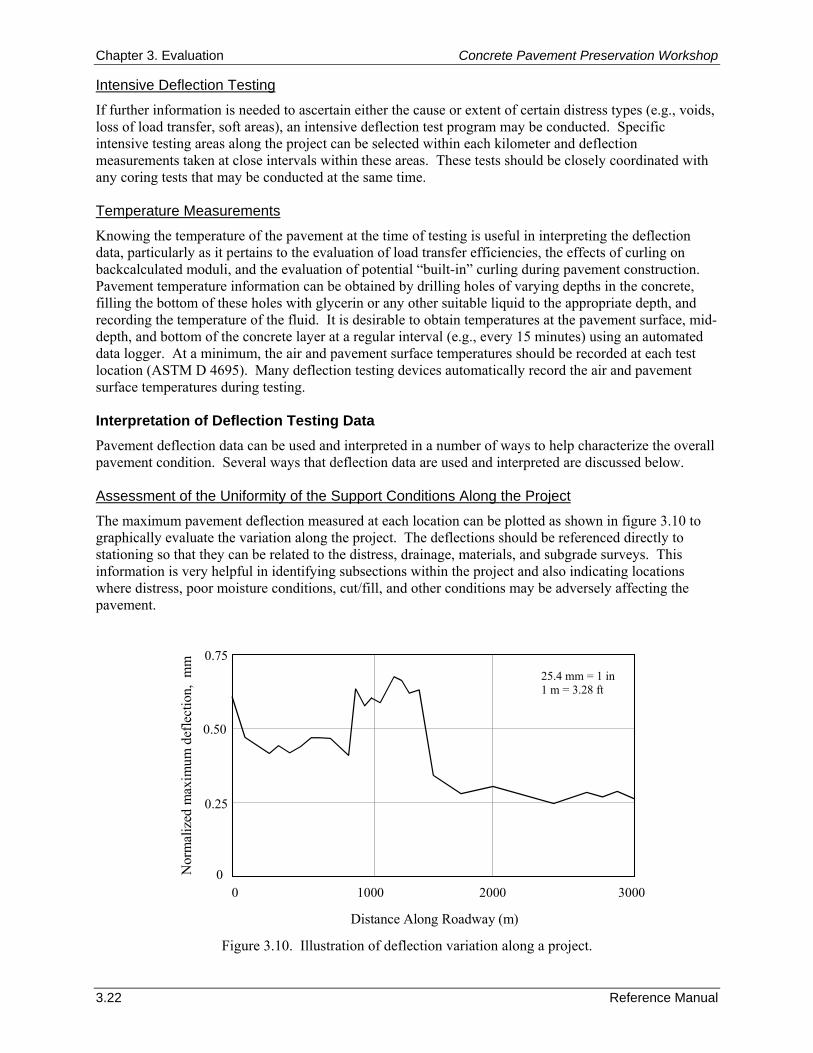
Chapter 3. Evaluation Concrete Pavement Preservation Workshop
3.22 Reference Manual
Intensive Deflection Testing
If further information is needed to ascertain either the cause or extent of certain distress types (e.g., voids, loss of load transfer, soft areas), an intensive deflection test program may be conducted. Specific intensive testing areas along the project can be selected within each kilometer and deflection measurements taken at close intervals within these areas. These tests should be closely coordinated with any coring tests that may be conducted at the same time. Temperature Measurements
Knowing the temperature of the pavement at the time of testing is useful in interpreting the deflection data, particularly as it pertains to the evaluation of load transfer efficiencies, the effects of curling on backcalculated moduli, and the evaluation of potential “built-in” curling during pavement construction. Pavement temperature information can be obtained by drilling holes of varying depths in the concrete, filling the bottom of these holes with glycerin or any other suitable liquid to the appropriate depth, and recording the temperature of the fluid. It is desirable to obtain temperatures at the pavement surface, mid-depth, and bottom of the concrete layer at a regular interval (e.g., every 15 minutes) using an automated data logger. At a minimum, the air and pavement surface temperatures should be recorded at each test location (ASTM D 4695). Many deflection testing devices automatically record the air and pavement surface temperatures during testing. Interpretation of Deflection Testing Data Pavement deflection data can be used and interpreted in a number of ways to help characterize the overall pavement condition. Several ways that deflection data are used and interpreted are discussed below. Assessment of the Uniformity of the Support Conditions Along the Project
The maximum pavement deflection measured at each location can be plotted as shown in figure 3.10 to graphically evaluate the variation along the project. The deflections should be referenced directly to stationing so that they can be related to the distress, drainage, materials, and subgrade surveys. This information is very helpful in identifying subsections within the project and also indicating locations where distress, poor moisture conditions, cut/fill, and other conditions may be adversely affecting the pavement.
0 1000 2000 3000
0.75
0.50
0.25
0
Distance Along Roadway (m)
Nor
mal
ized
max
imum
def
lect
ion,
mm
Figure 3.10. Illustration of deflection variation along a project.
25.4 mm = 1 in 1 m = 3.28 ft
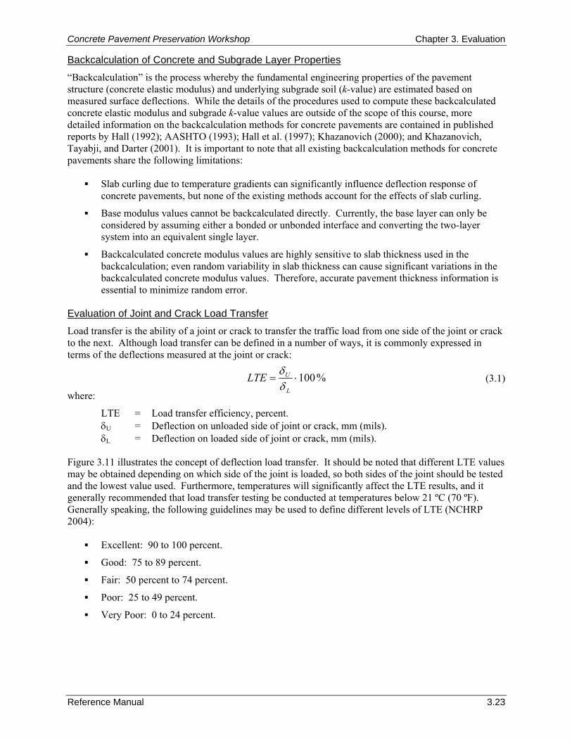
Concrete Pavement Preservation Workshop Chapter 3. Evaluation
Reference Manual 3.23
Backcalculation of Concrete and Subgrade Layer Properties
“Backcalculation” is the process whereby the fundamental engineering properties of the pavement structure (concrete elastic modulus) and underlying subgrade soil (k-value) are estimated based on measured surface deflections. While the details of the procedures used to compute these backcalculated concrete elastic modulus and subgrade k-value values are outside of the scope of this course, more detailed information on the backcalculation methods for concrete pavements are contained in published reports by Hall (1992); AASHTO (1993); Hall et al. (1997); Khazanovich (2000); and Khazanovich, Tayabji, and Darter (2001). It is important to note that all existing backcalculation methods for concrete pavements share the following limitations:
Slab curling due to temperature gradients can significantly influence deflection response of concrete pavements, but none of the existing methods account for the effects of slab curling.
Base modulus values cannot be backcalculated directly. Currently, the base layer can only be considered by assuming either a bonded or unbonded interface and converting the two-layer system into an equivalent single layer.
Backcalculated concrete modulus values are highly sensitive to slab thickness used in the backcalculation; even random variability in slab thickness can cause significant variations in the backcalculated concrete modulus values. Therefore, accurate pavement thickness information is essential to minimize random error.
Evaluation of Joint and Crack Load Transfer
Load transfer is the ability of a joint or crack to transfer the traffic load from one side of the joint or crack to the next. Although load transfer can be defined in a number of ways, it is commonly expressed in terms of the deflections measured at the joint or crack:
(3.1)
where:
LTE = Load transfer efficiency, percent. δU = Deflection on unloaded side of joint or crack, mm (mils). δL = Deflection on loaded side of joint or crack, mm (mils).
Figure 3.11 illustrates the concept of deflection load transfer. It should be noted that different LTE values may be obtained depending on which side of the joint is loaded, so both sides of the joint should be tested and the lowest value used. Furthermore, temperatures will significantly affect the LTE results, and it generally recommended that load transfer testing be conducted at temperatures below 21 ºC (70 ºF). Generally speaking, the following guidelines may be used to define different levels of LTE (NCHRP 2004):
Excellent: 90 to 100 percent.
Good: 75 to 89 percent.
Fair: 50 percent to 74 percent.
Poor: 25 to 49 percent.
Very Poor: 0 to 24 percent.
%100⋅=L
ULTEδδ
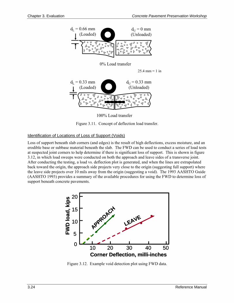
Chapter 3. Evaluation Concrete Pavement Preservation Workshop
3.24 Reference Manual
dL = 0.66 mm(Loaded)
0% Load transfer
100% Load transfer
dU = 0 mm(Unloaded)
dL = 0.33 mm(Loaded)
dU = 0.33 mm(Unloaded)
20
Corner Deflection, milli-inches
FWD
load
, kip
s
10 20 30 40 50
LEAVE
APPROACH15
10
5
0
20
Corner Deflection, milli-inches
FWD
load
, kip
s
10 20 30 40 50
LEAVE
APPROACH15
10
5
0
Figure 3.11. Concept of deflection load transfer.
Identification of Locations of Loss of Support (Voids)
Loss of support beneath slab corners (and edges) is the result of high deflections, excess moisture, and an erodible base or subbase material beneath the slab. The FWD can be used to conduct a series of load tests at suspected joint corners to help determine if there is significant loss of support. This is shown in figure 3.12, in which load sweeps were conducted on both the approach and leave sides of a transverse joint. After conducting the testing, a load vs. deflection plot is generated, and when the lines are extrapolated back toward the origin, the approach side projects very close to the origin (suggesting full support) where the leave side projects over 10 mils away from the origin (suggesting a void). The 1993 AASHTO Guide (AASHTO 1993) provides a summary of the available procedures for using the FWD to determine loss of support beneath concrete pavements.
Figure 3.12. Example void detection plot using FWD data.
25.4 mm = 1 in
Concrete Pavement Preservation Workshop Chapter 3. Evaluation
Reference Manual 3.25
7. ROUGHNESS AND SURFACE FRICTION TESTING As part of the pavement evaluation process, it is important to assess a pavement’s functional performance, which refers to how well the pavement is providing a smooth, safe ride to the traveling public. Two easily measurable characteristics that give an indication of a pavement’s functional condition are roughness and surface friction. Excessive roughness can create user discomfort and irritation and can lead to increased vehicle operating costs, user delay, and crashes. Inadequate surface friction can also contribute to crashes, especially under wet weather conditions. Definitions This section defines a number of important roughness- and friction-related terms. For convenience, these definitions are presented in alphabetical order.
Pavement Roughness. In its broadest sense, pavement roughness is defined as “the deviations of a surface from a true planar surface with characteristic dimensions that affect vehicle dynamics, ride quality, dynamic loads, and drainage” (Sayers 1985). Surface irregularities that influence pavement roughness can generally be divided into those that are built into the pavement during construction (e.g., bumps or depressions) and those that develop after construction as the result of developing distresses (e.g., cracking or faulting). Pavement roughness is now commonly expressed in terms of the international roughness index (IRI).
Pavement Surface Friction. Pavement surface friction (sometimes referred to as “skid resistance”) is the force developed at the tire-pavement interface that resists sliding when braking forces are applied to the vehicle tires (Dahir and Gramling 1990). Surface friction is largely influenced by the pavement’s texture (described in more detail below) and surface drainage characteristics. Adequate surface drainage (i.e., cross slope) influences pavement surface friction by assisting water runoff from the pavement surface.
Pavement Texture. The feature of the road surface that ultimately determines most of the tire/road interactions including wet friction, noise, splash and spray, rolling resistance, and tire wear is pavement texture (Henry 2000). Pavement texture is typically divided into categories of microtexture, macrotexture, and megatexture based on wavelength and vertical amplitude characteristics (Henry 2000; Gothié 2000):
– Microtexture—wavelengths of 1 μm to 0.5 mm (0.00004 to 0.02 in) with a vertical amplitude ranging between 1μm and 0.2 mm (0.00004 to 0.008 in). Microtexture is the surface “roughness” of the individual coarse aggregate particles and of the binder, and contributes to friction through adhesion with vehicle tires). For concrete surfaces constructed for speeds under 80 km/h (50 mi/h), microtexture is usually all that is needed to provide adequate stopping in wet weather conditions (Hibbs and Larson 1996).
– Macrotexture—wavelengths of 0.5 mm to 50 mm (0.02 to 2 in) with a vertical amplitude ranging between 0.1 mm and 20 mm (0.004 to 0.8 in). Macrotexture refers to the overall texture of the pavement, which in concrete pavements is controlled by the surface finish (tining). For concrete pavements constructed for speeds greater than or equal to 80 km/h (50 mph), good macrotexture is needed to reduce the water film thickness and prevent hydroplaning (Hibbs and Larson 1996). The difference between microtexture and macrotexture (and the relative different degrees of each) is illustrated in figure 3.13.
– Megatexture—wavelengths of 50 mm to 500 mm (2 to 20 in), with a vertical amplitude ranging between 0.1 mm and 50 mm (0.004 to 2 in). This level of texture is generally a characteristic or a consequence of deterioration of the surface.
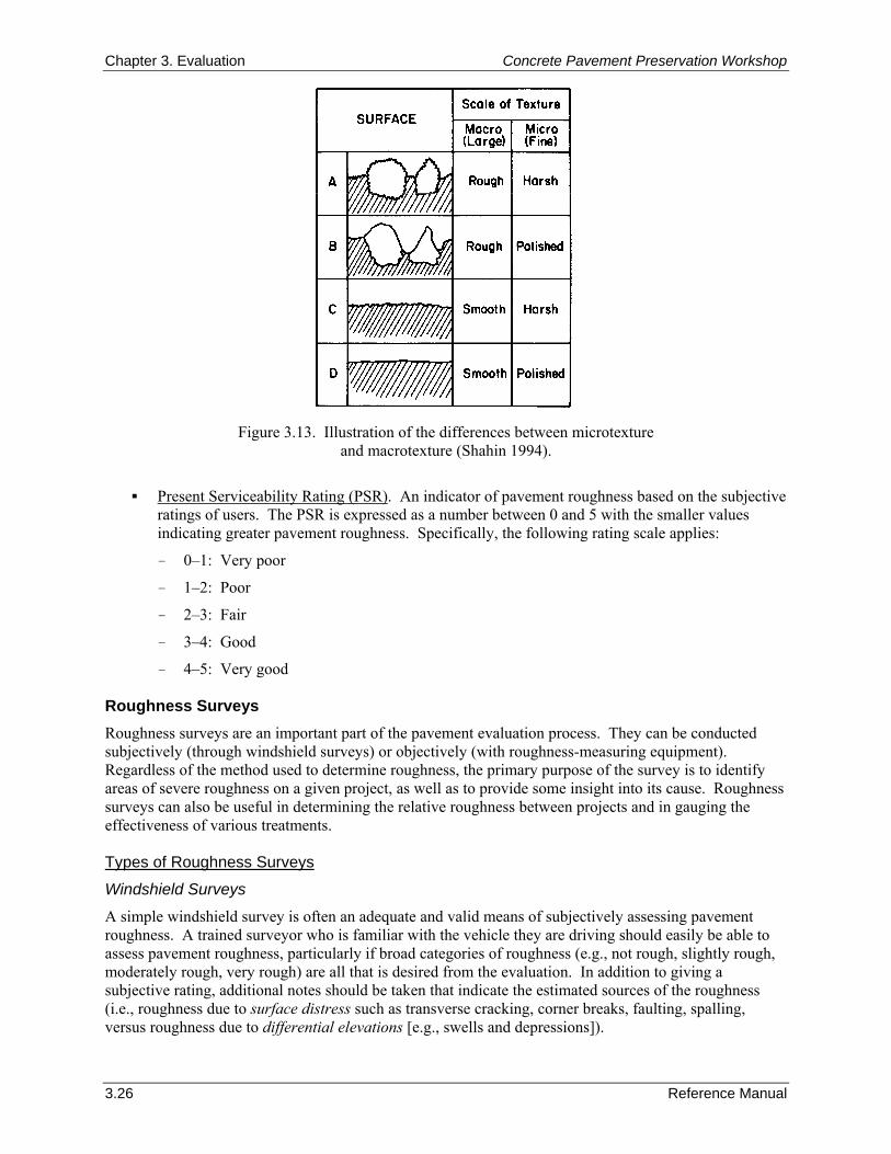
Chapter 3. Evaluation Concrete Pavement Preservation Workshop
3.26 Reference Manual
Figure 3.13. Illustration of the differences between microtexture
and macrotexture (Shahin 1994).
Present Serviceability Rating (PSR). An indicator of pavement roughness based on the subjective
ratings of users. The PSR is expressed as a number between 0 and 5 with the smaller values indicating greater pavement roughness. Specifically, the following rating scale applies:
– 0–1: Very poor
– 1–2: Poor
– 2–3: Fair
– 3–4: Good
– 4–5: Very good Roughness Surveys Roughness surveys are an important part of the pavement evaluation process. They can be conducted subjectively (through windshield surveys) or objectively (with roughness-measuring equipment). Regardless of the method used to determine roughness, the primary purpose of the survey is to identify areas of severe roughness on a given project, as well as to provide some insight into its cause. Roughness surveys can also be useful in determining the relative roughness between projects and in gauging the effectiveness of various treatments. Types of Roughness Surveys
Windshield Surveys
A simple windshield survey is often an adequate and valid means of subjectively assessing pavement roughness. A trained surveyor who is familiar with the vehicle they are driving should easily be able to assess pavement roughness, particularly if broad categories of roughness (e.g., not rough, slightly rough, moderately rough, very rough) are all that is desired from the evaluation. In addition to giving a subjective rating, additional notes should be taken that indicate the estimated sources of the roughness (i.e., roughness due to surface distress such as transverse cracking, corner breaks, faulting, spalling, versus roughness due to differential elevations [e.g., swells and depressions]).
Concrete Pavement Preservation Workshop Chapter 3. Evaluation
Reference Manual 3.27
Roughness Testing
Objective roughness testing is conducted using commercially available roughness-measuring equipment. Modern roughness-measuring equipment used on pavement evaluation projects can typically be divided into two general categories: response-type road roughness measuring systems (RTRRMS) and inertial road profiling systems (IRPS). The primary difference between these two categories is that RTRRMS measure vehicle response to pavement roughness while IRPS measure actual pavement profiles. Most highway agencies are using IRPS to monitor the roughness of their pavement network. To be of most use for the evaluation of a project, it is recommended that the roughness equipment traverse the project in each lane and obtain a representative roughness index for each 0.16 km (0.1 mi) increment. Roughness equipment that only measures one wheelpath should measure the right wheelpath in the direction of traffic for the outer and inner lanes. Special efforts should be made to ensure that the equipment is properly calibrated before its use to eliminate potential equipment deviations over time (Sayers and Karamihas 1998). A particular concern when testing on concrete pavements is the effect of daily temperature cycles on the measured roughness (Gillespie et al. 1999). On days where the air temperature changes significantly throughout the day, slab curling effects may be introduced that cause significant variations in the measured pavement profile over the course of the day. These effects are more noticeable on short-jointed concrete pavements, and will result in the highest level of roughness occurring in the early morning hours when the slabs are more likely to be curled up. Thus, for project-level profiling, several repeat runs of the project at different times during the day may be necessary to quantify the temperature effects. Types of Roughness Indices
The roughness index to be used on a project is very much dependent on the type of method and type of equipment used to collect the roughness data. One important aspect to remember in selecting an appropriate roughness index is that, ideally, it should be strongly correlated with user response. All roughness indices can be grouped into three general categories: subjective ratings, mechanical filter-based numerics, and profile-based numerics (Paterson 1987). Each of these roughness index types is discussed in more detail in the following sections. Subjective Ratings (Serviceability)
Subjective roughness assessments determined while conducting a windshield survey are typically expressed as ratings of serviceability. The concept of serviceability was developed at the AASHO Road Test that was conducted in the late 1950s (Carey and Irick 1960; Highway Research Board 1962) and, as previously mentioned, is based on a scale of 0 to 5. The PSR was used in the development of the AASHO pavement design procedure and remains an integral part of the current AASHTO procedures for both new pavement design and overlay design (AASHTO 1993). Mechanical Filter-Based Indices
RTRRM systems (such as the Mays Ride Meter or BPR Roughometer) measure the cumulative relative displacement between the axle and the vehicle body and then average that value over some distance of roadway; the resulting roughness index is reported in terms of vertical deviation over distance of roadway traveled (e.g., m/km [in/mi]). Examples of mechanical filter-based indices include the Mays Ride Number (MRN) and the Profile Index (PI) (measured with a California-type profilograph). Summary numerics measured by response-type systems, calibrated to a profile or other numeric in some cases, are reported to not correlate well with user response to roadway roughness (Smith et al. 1997). This poor correlation can be attributed to the inability of response-type systems to measure and sufficiently weight the surface profile wavelengths that are most related to user response and to overall variability within these systems (Smith et al. 1997).
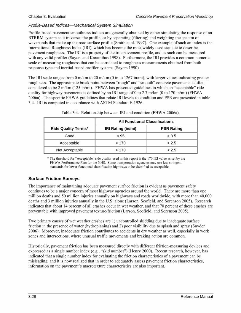
Chapter 3. Evaluation Concrete Pavement Preservation Workshop
3.28 Reference Manual
Profile-Based Indices—Mechanical System Simulation
Profile-based pavement smoothness indices are generally obtained by either simulating the response of an RTRRM system as it traverses the profile, or by separating (filtering) and weighting the spectra of wavebands that make up the road surface profile (Smith et al. 1997). One example of such an index is the International Roughness Index (IRI), which has become the most widely used statistic to describe pavement roughness. The IRI is a property of the true pavement profile, and as such can be measured with any valid profiler (Sayers and Karamihas 1998). Furthermore, the IRI provides a common numeric scale of measuring roughness that can be correlated to roughness measurements obtained from both response-type and inertial-based profiler systems (Sayers 1990). The IRI scale ranges from 0 m/km to 20 m/km (0 in to 1267 in/mi), with larger values indicating greater roughness. The approximate break point between “rough” and “smooth” concrete pavements is often considered to be 2 m/km (125 in/mi). FHWA has presented guidelines in which an “acceptable” ride quality for highway pavements is defined by an IRI range of 0 to 2.7 m/km (0 to 170 in/mi) (FHWA 2006a). The specific FHWA guidelines that relate IRI levels to condition and PSR are presented in table 3.4. IRI is computed in accordance with ASTM Standard E-1926.
Table 3.4. Relationship between IRI and condition (FHWA 2006a).
All Functional Classifications
Ride Quality Terms* IRI Rating (in/mi) PSR Rating
Good < 95 > 3.5
Acceptable < 170 > 2.5
Not Acceptable > 170 < 2.5
* The threshold for “Acceptable” ride quality used in this report is the 170 IRI value as set by the FHWA Performance Plan for the NHS. Some transportation agencies may use less stringent standards for lower functional classification highways to be classified as acceptable.
Surface Friction Surveys The importance of maintaining adequate pavement surface friction is evident as pavement safety continues to be a major concern of most highway agencies around the world. There are more than one million deaths and 50 million injuries annually on highways and roads worldwide, with more than 40,000 deaths and 3 million injuries annually in the U.S. alone (Larson, Scofield, and Sorenson 2005). Research indicates that about 14 percent of all crashes occur in wet weather, and that 70 percent of these crashes are preventable with improved pavement texture/friction (Larson, Scofield, and Sorenson 2005). Two primary causes of wet weather crashes are 1) uncontrolled skidding due to inadequate surface friction in the presence of water (hydroplaning) and 2) poor visibility due to splash and spray (Snyder 2006). Moreover, inadequate friction contributes to accidents in dry weather as well, especially in work zones and intersections, where unusual traffic movements and braking action are common. Historically, pavement friction has been measured directly with different friction-measuring devices and expressed as a single number index (e.g., “skid number”) (Henry 2000). Recent research, however, has indicated that a single number index for evaluating the friction characteristics of a pavement can be misleading, and it is now realized that in order to adequately assess pavement friction characteristics, information on the pavement’s macrotexture characteristics are also important.
Concrete Pavement Preservation Workshop Chapter 3. Evaluation
Reference Manual 3.29
Types of Friction Measuring Equipment
There are four basic types of full scale devices used to obtain direct measurements of pavement surface friction. These include locked wheel, side force, fixed slip, and variable slip testers. Each of these equipment types are described in more detail below. Locked Wheel Testers
Locked wheel testing devices simulate emergency braking conditions for vehicles without antilock breaks (i.e., a 100 percent slip condition). Today, the majority of agencies in the United States measure pavement friction with an ASTM locked-wheel trailer in accordance with ASTM E 274 (Henry 2000). In this procedure, the locked-wheel trailer is towed on a pavement that has been wetted with a specified amount of water, and then a braking force is applied. Testing can be done with either a ribbed (treaded) or blank (smooth) tire, but measurements using the blank tire are reportedly better indicators of the pavement’s macrotexture (Dahir and Gramling 1990). Measurements made with the locked-wheel trailer are reported as a “skid number,” that is, the measured value of friction times 100. Skid numbers are reported in the form of: SN(Test Speed [in mph]) followed by an R if a ribbed tire was used or and S if a smooth tread tire. If the test speed is expressed in km/h it is enclosed in parentheses. For example, if a ribbed tire was used in a locked-wheel trailer test at a test speed of 80 km/h (50 mph), the skid number would be reported as SN(80)R or SN50R (metric and English units, respectively). Side Force Testers
Side force testers are designed to simulate a vehicle’s ability to maintain control in curves. They function by maintaining a test wheel in a plane at an angle (the yaw angle) to the direction of motion, while the wheel is allowed to roll freely (i.e., a 0 percent slip condition) (Henry 2000). The developed side force (cornering force) is then measured perpendicular to the plane of rotation. An advantage of these devices is that they measure continuously through the test section while locked wheel devices only sample the friction over the distance while the wheel is locked (the wheel is typically locked for only one second before the brake is released) (Henry 2000). Examples of specific side force testing equipment include the MuMeter and the Sideway-force Coefficient Routine Investigation Machine (SCRIM), both of which originated in the United Kingdom. Fixed Slip Testers
The fixed and variable slip methods are used to simulate a vehicle’s ability to brake while using antilock brakes. Fixed slip devices operate at a constant slip, usually between 10 and 20 percent slip (i.e., the test wheel is driven at a lower angular velocity than its free rolling velocity) (Henry 2000). As with the side force testers, the largest advantage of using a fixed slip tester is that these testers can also be operated continuously over the test section without excessive wear of the test tire. Examples of specific fixed slip testing devices are the Griptester and the SAAB Friction Tester. Variable Slip Testers
Variable slip testers are similar to fixed slip devices, except that instead of using one constant slip ratio during a test, the variable slip devices sweep through a predetermined set of slip ratios (in accordance with ASTM Standard E 1859) (Henry 2000). An example of a specific variable slip device is the Norsemeter Road Analyzer and Recorder (ROAR) (although this device has not typically been used in the United States for friction testing). Friction Testing Procedures
The pavement friction should be measured at uniform increments along the project in each traffic lane. As a minimum, most states test in the left wheel path of the driving lane (under normal conditions, this is the location where the surface friction is minimum). The increments should be tied into the mile post
Chapter 3. Evaluation Concrete Pavement Preservation Workshop
3.30 Reference Manual
markers so that intersections, interchanges, curves, and hills can be identified. Sharp curves are particularly important to consider. Measuring Pavement Surface Texture In recent years, it has been recognized that measuring pavement surface texture is necessary to accurately represent a pavement’s true functional characteristics. As described previously, pavement texture is primarily divided into three categories: microtexture, macrotexture, and megatexture. While all three are known to influence the pavement’s functional performance, it is the surface macrotexture that is most often assessed with texture measuring methods. Traditionally, the sand patch test has been used to assess pavement macrotexture, which produces an indicator of surface texture known as the mean texture depth (MTD). To provide adequate surface friction, the average MTD should be 0.8 mm (0.03 in) with a minimum of 0.5 mm (0.02 in) for any individual test (Hibbs and Larson 1996). In the past decade, advances in laser technology and computational power have led to the development of systems that measure pavement longitudinal profile at traffic speeds (Henry 2000). Analysis of this data can be used to compute a mean profile depth (MPD), which can be used to estimate the more traditional MTD measurement. The MPD is measured using modern high-speed vehicle-mounted laser-based measuring devices or with portable devices such as the circular track meter (CTMeter). Evaluation of Roughness, Friction, and Texture Survey Results Any collected roughness, friction, and texture data should be evaluated in much the same way as pavement condition survey data. These measured data should be summarized so that a clear picture of the existing functional condition can be obtained by those involved in making design decisions. As with condition survey data, strip charts can be a useful way of showing the various condition deficiencies along the project. These should include the location and severity of roughness and surface friction characteristics along the project by lane. Strip charts can also aid in the selection of sites for further detailed materials and pavement testing. When selecting an appropriate treatment alternative, it is also important to recognize the visible pavement distresses that are also indicative of potential roughness or friction problems. For example, common distresses that greatly influence concrete pavement roughness include:
Cracking (corner breaks, durability, longitudinal, and transverse) and crack deterioration.
Transverse joint faulting.
Transverse joint spalling.
Punchouts.
Patch deterioration. Surface conditions that are indicative of potential surface friction problems include:
Smooth macrotexture that may be the result of inadequate finishing texturing.
Polishing caused by soft aggregate.
Inadequate pavement cross slopes that result in slow runoff of water from the pavement surface. It is informative to view these poor friction conditions in conjunction with wet-weather crash data to see if there are any correlations. Overall, the combined results obtained from the roughness and friction assessments can be used to determine if functional improvements are needed.
Concrete Pavement Preservation Workshop Chapter 3. Evaluation
Reference Manual 3.31
8. FIELD SAMPLING AND TESTING Introduction Because they should be in relatively good condition, most pavement preservation candidate projects will not require field sampling or testing as part of the pavement evaluation process. Some exceptions to this might be indications of materials-related distress in the concrete, the presence of peculiar distresses, or areas suggestive of poor support conditions. When conducted, the primary purposes of field sampling and testing are to help observe subsurface pavement conditions, verify pavement layer types and thicknesses, and retrieve samples for later laboratory testing and analyses. Many different field and laboratory tests are available to determine the subgrade and paving material properties, especially those that are linked to pavement performance. The types and amount of material sampling and testing is primarily dependent upon the following factors:
Observed pavement distress. The type, severity, extent, and variation of visible distress on a pavement greatly affect the locations and amount of field sampling and testing. If the distress is uniformly spread over the project, sampling is most likely conducted in a random (objective) manner. Otherwise, sampling can be targeted in areas of high distress concentrations.
Variability. The variability along the project site will affect the amount of material and sampling required. Projects with greater variability in material properties will require a greater amount of testing in order that this variability can be properly characterized and accounted for.
Traffic volume. The locations and number of allowable samples may be limited on higher trafficked roadways due to worker and driver safety concerns. Such lane closure restrictions and safety related issues are typically not an issue on roadways with lower traffic volumes.
Economics. Most agencies have a limited budget that determines the types and amount of sampling and testing that can be conducted for a given project. Engineering judgment must be used to determine a sampling and testing plan that minimizes the amount of testing required to adequately assess a pavement’s condition, while staying within the provided budget constraints.
The typical field sampling techniques, in situ field testing methods, and standard laboratory testing procedures used in a detailed material investigation are discussed in this section. Common Field Sampling and Testing Methods Coring
By far, the most common field sampling method is coring, which is the process of cutting cylindrical material samples (cores) from an in-place pavement. Coring is accomplished with the use of a hollow, cylindrical, diamond-tipped core barrel attached to a rotary core drill. The drill is anchored (either to the pavement or to a coring rig) and held perpendicular to the pavement surface while the rotating core barrel is used to slowly cut into the pavement surface. Cores are drilled and retrieved from the pavement and tested in accordance with ASTM C-42, Standard Method for Obtaining and Testing Drilled Cores and Sawed Beams of Concrete and ASTM C-823, Standard Practice for Examination and Sampling of Hardened Concrete in Construction. Coring is most often used to determine/verify layer types and thicknesses, as well as to provide samples (concrete slab and stabilized layers only) for strength testing and possible petrographic examination. A visual inspection of retrieved cores can also provide valuable information when trying to assess the causes of visual distress or poor pavement performance. Cores are particularly useful at identifying material consistency problems such as honeycombing in concrete. Cores are commonly cut with diameters of 50-, 100-, or 150-mm (2-, 4-, or 6-in), the selection of which depends on the purpose. If thickness verification is all that is needed, 50-mm (2-in) diameter cores are
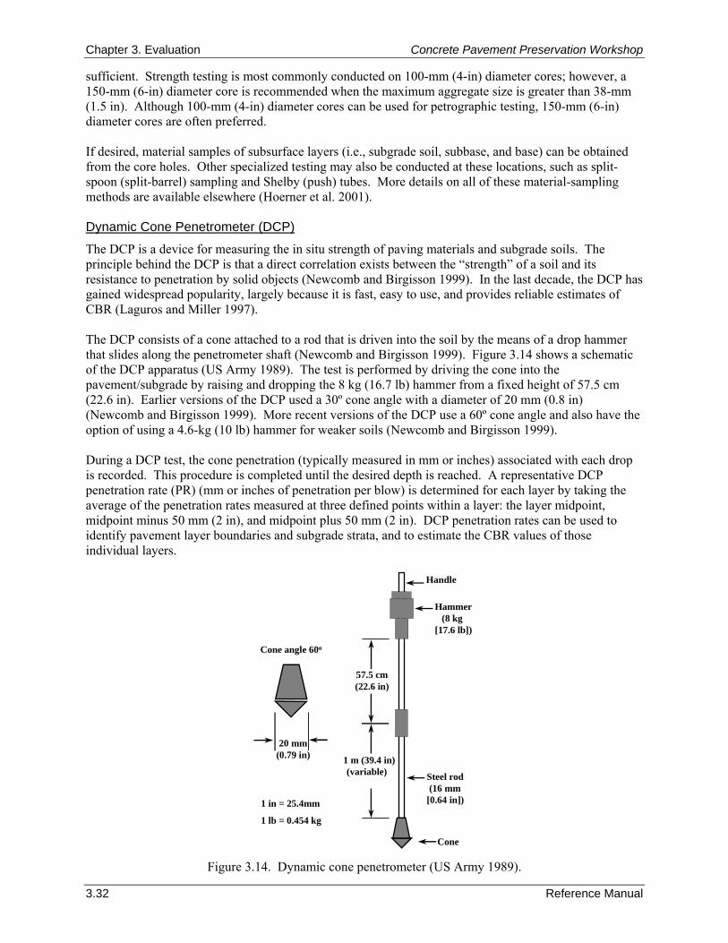
Chapter 3. Evaluation Concrete Pavement Preservation Workshop
3.32 Reference Manual
Cone angle 60o
Handle
Hammer(8 kg
[17.6 lb])
Cone
Steel rod(16 mm
[0.64 in])
57.5 cm(22.6 in)
1 m (39.4 in)(variable)
1 in = 25.4mm
1 lb = 0.454 kg
20 mm(0.79 in)
sufficient. Strength testing is most commonly conducted on 100-mm (4-in) diameter cores; however, a 150-mm (6-in) diameter core is recommended when the maximum aggregate size is greater than 38-mm (1.5 in). Although 100-mm (4-in) diameter cores can be used for petrographic testing, 150-mm (6-in) diameter cores are often preferred. If desired, material samples of subsurface layers (i.e., subgrade soil, subbase, and base) can be obtained from the core holes. Other specialized testing may also be conducted at these locations, such as split-spoon (split-barrel) sampling and Shelby (push) tubes. More details on all of these material-sampling methods are available elsewhere (Hoerner et al. 2001). Dynamic Cone Penetrometer (DCP)
The DCP is a device for measuring the in situ strength of paving materials and subgrade soils. The principle behind the DCP is that a direct correlation exists between the “strength” of a soil and its resistance to penetration by solid objects (Newcomb and Birgisson 1999). In the last decade, the DCP has gained widespread popularity, largely because it is fast, easy to use, and provides reliable estimates of CBR (Laguros and Miller 1997). The DCP consists of a cone attached to a rod that is driven into the soil by the means of a drop hammer that slides along the penetrometer shaft (Newcomb and Birgisson 1999). Figure 3.14 shows a schematic of the DCP apparatus (US Army 1989). The test is performed by driving the cone into the pavement/subgrade by raising and dropping the 8 kg (16.7 lb) hammer from a fixed height of 57.5 cm (22.6 in). Earlier versions of the DCP used a 30º cone angle with a diameter of 20 mm (0.8 in) (Newcomb and Birgisson 1999). More recent versions of the DCP use a 60º cone angle and also have the option of using a 4.6-kg (10 lb) hammer for weaker soils (Newcomb and Birgisson 1999). During a DCP test, the cone penetration (typically measured in mm or inches) associated with each drop is recorded. This procedure is completed until the desired depth is reached. A representative DCP penetration rate (PR) (mm or inches of penetration per blow) is determined for each layer by taking the average of the penetration rates measured at three defined points within a layer: the layer midpoint, midpoint minus 50 mm (2 in), and midpoint plus 50 mm (2 in). DCP penetration rates can be used to identify pavement layer boundaries and subgrade strata, and to estimate the CBR values of those individual layers.
Figure 3.14. Dynamic cone penetrometer (US Army 1989).
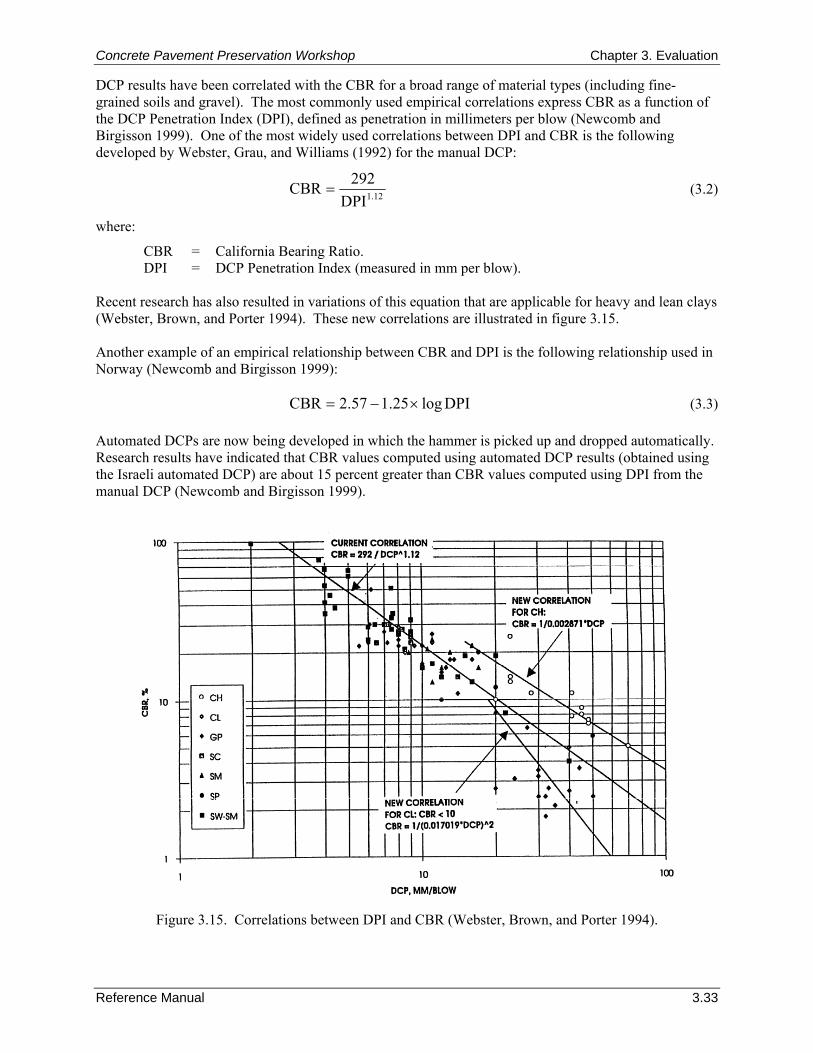
Concrete Pavement Preservation Workshop Chapter 3. Evaluation
Reference Manual 3.33
DCP results have been correlated with the CBR for a broad range of material types (including fine-grained soils and gravel). The most commonly used empirical correlations express CBR as a function of the DCP Penetration Index (DPI), defined as penetration in millimeters per blow (Newcomb and Birgisson 1999). One of the most widely used correlations between DPI and CBR is the following developed by Webster, Grau, and Williams (1992) for the manual DCP:
12.1DPI292CBR = (3.2)
where:
CBR = California Bearing Ratio. DPI = DCP Penetration Index (measured in mm per blow).
Recent research has also resulted in variations of this equation that are applicable for heavy and lean clays (Webster, Brown, and Porter 1994). These new correlations are illustrated in figure 3.15. Another example of an empirical relationship between CBR and DPI is the following relationship used in Norway (Newcomb and Birgisson 1999):
DPIlog25.157.2CBR ×−= (3.3) Automated DCPs are now being developed in which the hammer is picked up and dropped automatically. Research results have indicated that CBR values computed using automated DCP results (obtained using the Israeli automated DCP) are about 15 percent greater than CBR values computed using DPI from the manual DCP (Newcomb and Birgisson 1999).
Figure 3.15. Correlations between DPI and CBR (Webster, Brown, and Porter 1994).
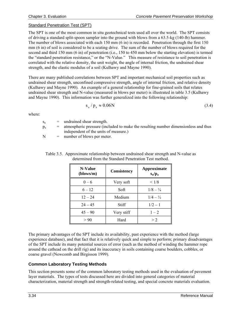
Chapter 3. Evaluation Concrete Pavement Preservation Workshop
3.34 Reference Manual
Standard Penetration Test (SPT)
The SPT is one of the most common in situ geotechnical tests used all over the world. The SPT consists of driving a standard split-spoon sampler into the ground with blows from a 63.5-kg (140-lb) hammer. The number of blows associated with each 150 mm (6 in) is recorded. Penetration through the first 150 mm (6 in) of soil is considered to be a seating drive. The sum of the number of blows required for the second and third 150 mm (6 in) of penetration (i.e., 150 to 450 mm below the starting elevation) is termed the “standard penetration resistance,” or the “N-Value.” This measure of resistance to soil penetration is correlated with the relative density, the unit weight, the angle of internal friction, the undrained shear strength, and the elastic modulus of a soil (Kulhawy and Mayne 1990). There are many published correlations between SPT and important mechanical soil properties such as undrained shear strength, unconfined compressive strength, angle of internal friction, and relative density (Kulhawy and Mayne 1990). An example of a general relationship for fine-grained soils that relates undrained shear strength and N-value (measured in blows per meter) is illustrated in table 3.5 (Kulhawy and Mayne 1990). This information was further generalized into the following relationship:
N06.0p/s au ≈ (3.4)
where:
su = undrained shear strength. pa = atmospheric pressure (included to make the resulting number dimensionless and thus
independent of the units of measure.) N = number of blows per meter.
Table 3.5. Approximate relationship between undrained shear strength and N-value as determined from the Standard Penetration Test method.
N-Value (blows/m) Consistency Approximate
su/pa
0 – 6 Very soft < 1/8
6 – 12 Soft 1/8 – ¼
12 – 24 Medium 1/4 – ½
24 – 45 Stiff 1/2 – 1
45 – 90 Very stiff 1 – 2
> 90 Hard > 2
The primary advantages of the SPT include its availability, past experience with the method (large experience database), and that fact that it is relatively quick and simple to perform; primary disadvantages of the SPT include its many potential sources of error (such as the method of winding the hammer rope around the cathead on the drill rig) and its inaccuracy in soils containing coarse boulders, cobbles, or coarse gravel (Newcomb and Birgisson 1999). Common Laboratory Testing Methods This section presents some of the common laboratory testing methods used in the evaluation of pavement layer materials. The types of tests discussed here are divided into general categories of material characterization, material strength and strength-related testing, and special concrete materials evaluation.
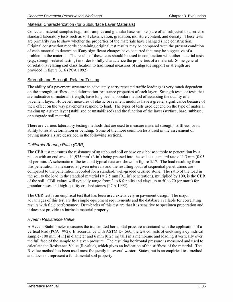
Concrete Pavement Preservation Workshop Chapter 3. Evaluation
Reference Manual 3.35
Material Characterization (for Subsurface Layer Materials)
Collected material samples (e.g., soil samples and granular base samples) are often subjected to a series of standard laboratory tests such as soil classification, gradation, moisture content, and density. These tests are primarily run to show whether the properties of the materials have changed since construction. Original construction records containing original test results may be compared with the present condition of each material to determine if any significant changes have occurred that may be suggestive of a problem in the material. The results of these tests should be used in conjunction with other material tests (e.g., strength-related testing) in order to fully characterize the properties of a material. Some general correlations relating soil classification to traditional measures of subgrade support or strength are provided in figure 3.16 (PCA 1992). Strength and Strength-Related Testing
The ability of a pavement structure to adequately carry repeated traffic loadings is very much dependent on the strength, stiffness, and deformation-resistance properties of each layer. Strength tests, or tests that are indicative of material strength, have long been a popular method of assessing the quality of a pavement layer. However, measures of elastic or resilient modulus have a greater significance because of their effect on the way pavements respond to load. The types of tests used depend on the type of material making up a given layer (stabilized or unstabilized) and the function of the layer (surface, base, subbase, or subgrade soil material). There are various laboratory testing methods that are used to measure material strength, stiffness, or its ability to resist deformation or bending. Some of the more common tests used in the assessment of paving materials are described in the following sections. California Bearing Ratio (CBR)
The CBR test measures the resistance of an unbound soil or base or subbase sample to penetration by a piston with an end area of 1,935 mm2 (3 in2) being pressed into the soil at a standard rate of 1.3 mm (0.05 in) per min. A schematic of the test and typical data are shown in figure 3.17. The load resulting from this penetration is measured at given intervals and the resulting loads at sequential penetrations are compared to the penetration recorded for a standard, well-graded crushed stone. The ratio of the load in the soil to the load in the standard material (at 2.5 mm [0.1 in] penetration), multiplied by 100, is the CBR of the soil. CBR values will typically range from 2 to 8 for silts and clays up to 50 to 70 (or more) for granular bases and high-quality crushed stones (PCA 1992). The CBR test is an empirical test that has been used extensively in pavement design. The major advantages of this test are the simple equipment requirements and the database available for correlating results with field performance. Drawbacks of this test are that it is sensitive to specimen preparation and it does not provide an intrinsic material property. Hveem Resistance Value
A Hveem Stabilometer measures the transmitted horizontal pressure associated with the application of a vertical load (PCA 1992). In accordance with ASTM D-1560, the test consists of enclosing a cylindrical sample (100 mm [4 in] in diameter and 6 mm [0.25 in] tall) in a membrane and loading it vertically over the full face of the sample to a given pressure. The resulting horizontal pressure is measured and used to calculate the Resistance Value (R-value), which gives an indication of the stiffness of the material. The R-value method has been used most frequently in several western States, but is an empirical test method and does not represent a fundamental soil property.
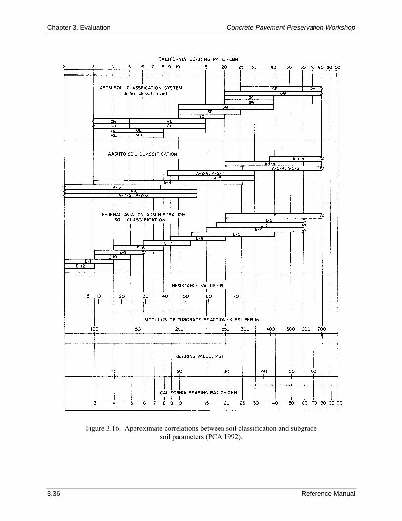
Chapter 3. Evaluation Concrete Pavement Preservation Workshop
3.36 Reference Manual
Figure 3.16. Approximate correlations between soil classification and subgrade soil parameters (PCA 1992).
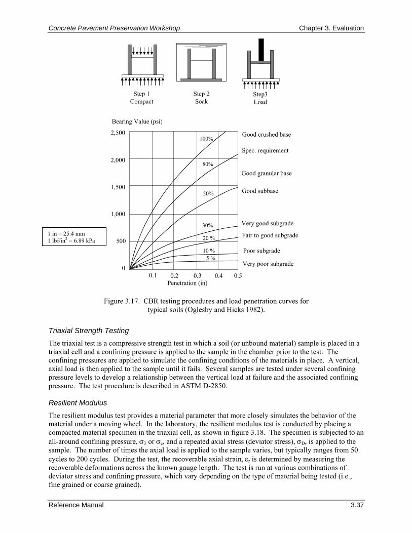
Concrete Pavement Preservation Workshop Chapter 3. Evaluation
Reference Manual 3.37
Penetration (in)
Bearing Value (psi)
Good crushed base
Spec. requirement
Good granular base
Good subbase
Very good subgrade
Fair to good subgrade
Poor subgrade
Very poor subgrade
500
0
1,000
1,500
2,000
2,500
0.1 0.2 0.3 0.4 0.5
100%
80%
50%
30%
20 %
10 %5 %
Step 1Compact
Step 2Soak
Step3Load
Figure 3.17. CBR testing procedures and load penetration curves for typical soils (Oglesby and Hicks 1982).
Triaxial Strength Testing
The triaxial test is a compressive strength test in which a soil (or unbound material) sample is placed in a triaxial cell and a confining pressure is applied to the sample in the chamber prior to the test. The confining pressures are applied to simulate the confining conditions of the materials in place. A vertical, axial load is then applied to the sample until it fails. Several samples are tested under several confining pressure levels to develop a relationship between the vertical load at failure and the associated confining pressure. The test procedure is described in ASTM D-2850. Resilient Modulus
The resilient modulus test provides a material parameter that more closely simulates the behavior of the material under a moving wheel. In the laboratory, the resilient modulus test is conducted by placing a compacted material specimen in the triaxial cell, as shown in figure 3.18. The specimen is subjected to an all-around confining pressure, σ3 or σc, and a repeated axial stress (deviator stress), σD, is applied to the sample. The number of times the axial load is applied to the sample varies, but typically ranges from 50 cycles to 200 cycles. During the test, the recoverable axial strain, εr is determined by measuring the recoverable deformations across the known gauge length. The test is run at various combinations of deviator stress and confining pressure, which vary depending on the type of material being tested (i.e., fine grained or coarse grained).
1 in = 25.4 mm 1 lbf/in2 = 6.89 kPa
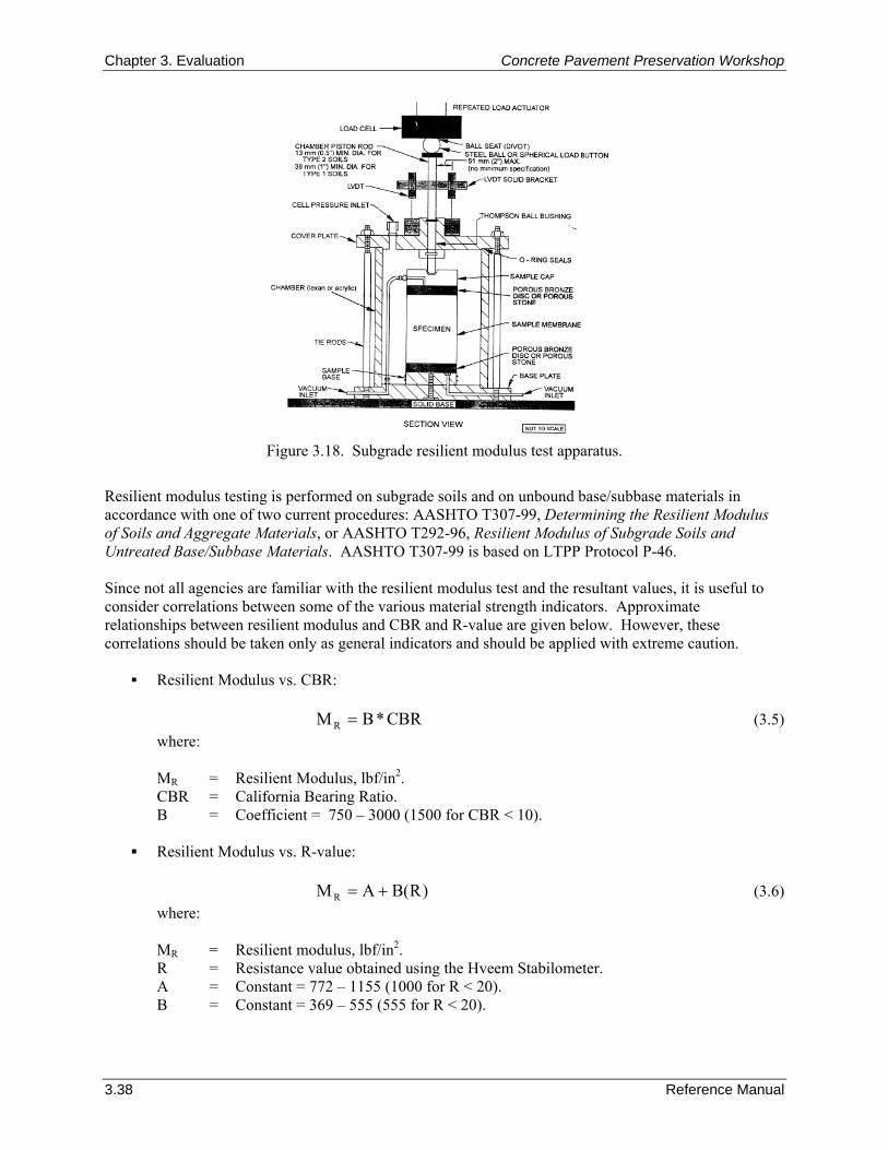
Chapter 3. Evaluation Concrete Pavement Preservation Workshop
3.38 Reference Manual
Figure 3.18. Subgrade resilient modulus test apparatus.
Resilient modulus testing is performed on subgrade soils and on unbound base/subbase materials in accordance with one of two current procedures: AASHTO T307-99, Determining the Resilient Modulus of Soils and Aggregate Materials, or AASHTO T292-96, Resilient Modulus of Subgrade Soils and Untreated Base/Subbase Materials. AASHTO T307-99 is based on LTPP Protocol P-46. Since not all agencies are familiar with the resilient modulus test and the resultant values, it is useful to consider correlations between some of the various material strength indicators. Approximate relationships between resilient modulus and CBR and R-value are given below. However, these correlations should be taken only as general indicators and should be applied with extreme caution.
Resilient Modulus vs. CBR:
CBR*BM R = (3.5) where: MR = Resilient Modulus, lbf/in2. CBR = California Bearing Ratio. B = Coefficient = 750 – 3000 (1500 for CBR < 10).
Resilient Modulus vs. R-value:
)R(BAM R += (3.6)
where: MR = Resilient modulus, lbf/in2. R = Resistance value obtained using the Hveem Stabilometer. A = Constant = 772 – 1155 (1000 for R < 20). B = Constant = 369 – 555 (555 for R < 20).
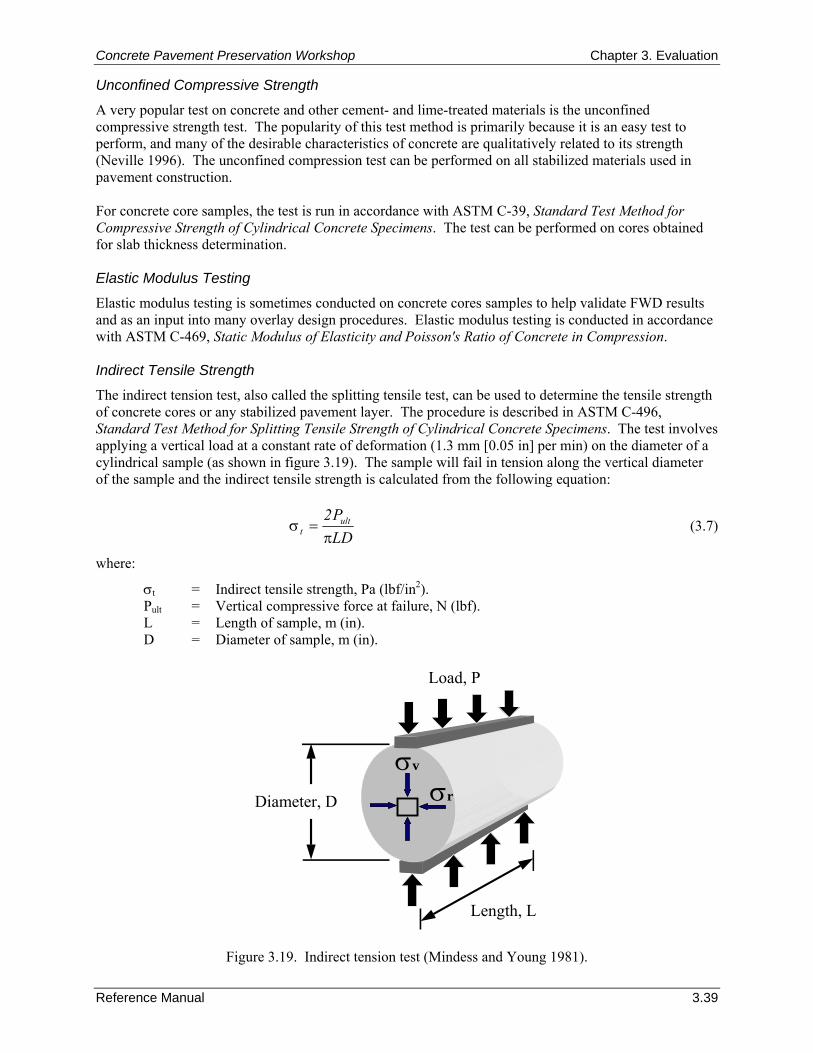
Concrete Pavement Preservation Workshop Chapter 3. Evaluation
Reference Manual 3.39
Unconfined Compressive Strength
A very popular test on concrete and other cement- and lime-treated materials is the unconfined compressive strength test. The popularity of this test method is primarily because it is an easy test to perform, and many of the desirable characteristics of concrete are qualitatively related to its strength (Neville 1996). The unconfined compression test can be performed on all stabilized materials used in pavement construction. For concrete core samples, the test is run in accordance with ASTM C-39, Standard Test Method for Compressive Strength of Cylindrical Concrete Specimens. The test can be performed on cores obtained for slab thickness determination. Elastic Modulus Testing
Elastic modulus testing is sometimes conducted on concrete cores samples to help validate FWD results and as an input into many overlay design procedures. Elastic modulus testing is conducted in accordance with ASTM C-469, Static Modulus of Elasticity and Poisson's Ratio of Concrete in Compression. Indirect Tensile Strength
The indirect tension test, also called the splitting tensile test, can be used to determine the tensile strength of concrete cores or any stabilized pavement layer. The procedure is described in ASTM C-496, Standard Test Method for Splitting Tensile Strength of Cylindrical Concrete Specimens. The test involves applying a vertical load at a constant rate of deformation (1.3 mm [0.05 in] per min) on the diameter of a cylindrical sample (as shown in figure 3.19). The sample will fail in tension along the vertical diameter of the sample and the indirect tensile strength is calculated from the following equation:
LDP2 ult
t π=σ (3.7)
where:
σt = Indirect tensile strength, Pa (lbf/in2). Pult = Vertical compressive force at failure, N (lbf). L = Length of sample, m (in). D = Diameter of sample, m (in).
Diameter, D
Load, P
σv
σr
Length, L
Figure 3.19. Indirect tension test (Mindess and Young 1981).
Chapter 3. Evaluation Concrete Pavement Preservation Workshop
3.40 Reference Manual
This test is particularly valuable for pavement evaluation purposes as it is performed on cores taken from the pavement. As with the compression testing, this test can be performed on cores obtained for slab thickness determination. Special Concrete Materials Evaluation Tests
In some cases, an existing concrete pavement may be exhibiting materials-related distresses (MRD) that is compromising the performance of the pavement. Materials-related distresses are those distresses that develop due to the concrete’s inability to maintain its integrity (changes in concrete microtexture) when subjected to changes in physical (environmental) and chemical mechanisms. MRD is generally visible as cracking or a degradation of the concrete such as scaling or spalling, often accompanied by some type of staining or exudate. The occurrence of MRD is a function of many factors, including the constituent materials (aggregate, cement, admixtures) and their proportions, the pavement’s location (maritime or inland), the climatic conditions (temperature, moisture) to which it is subjected, and the presence of external aggressive agents (e.g., roadway deicing chemicals) (Van Dam et al. 2002a). It is not uncommon for combinations of these factors to result in the occurrence of multiple types of MRD in a given pavement section. When multiple MRD types develop together, the process of determining the exact cause(s) of material failure is often complicated. Table 3.6 summarizes details of the most common MRD types, including information regarding their causes, typical time of appearance, and prevention (Van Dam et al. 2002a). When MRD is suspected of playing a role in the premature deterioration of concrete, laboratory tests are essential to help understand the underlying mechanisms at work (Van Dam et al. 2002b). Typical laboratory methods used to characterize PCC microstructure include optical microscopy (OM), staining tests, scanning electron microscopy (SEM), analytical chemistry, and x-ray diffraction (XRD). Optical microscopy using the stereo microscope and the petrographic microscope are recognized as the most versatile and widely applied tools for diagnosing causes of MRD. Staining tests are effective at identifying certain types of MRD. Electron microscopy is becoming more prevalent, especially for chemical identification of reaction products and other secondary phases using energy dispersive spectroscopy (Van Dam et al. 2002b). Analytical chemistry is an effective method of determining some of the key parameters of the concrete (e.g. water-to-cement ratio [w/c], chloride content). XRD is applicable in some cases, however, it is not widely used in the analysis of PCC. 9. SUMMARY This chapter presents guidelines and procedures on conducting an overall pavement project evaluation. A thorough pavement evaluation is absolutely essential to the identification of appropriate and cost-effective solutions to the observed problems. Many premature failures can be attributed to a lack of understanding about the cause or extent of pavement deterioration. A thorough pavement evaluation begins with the collection and review of all available historical data associated with a given project. This includes reviewing original design data, construction information, subgrade data, performance data, and so on. A collective review of this data often provides an engineer with valuable insight into why the pavement is performing the way it is. A pavement distress survey is the first and most fundamental pavement evaluation procedure. As part of the survey, pavement distress is defined in terms of type, severity, and amount in order to fully characterize the condition of the existing pavement. By knowing the type of distress, insight as to whether the distress is primarily load-related or primarily materials/climate-related can be gained, which in turn will assist in the selection of the appropriate treatment alternative.
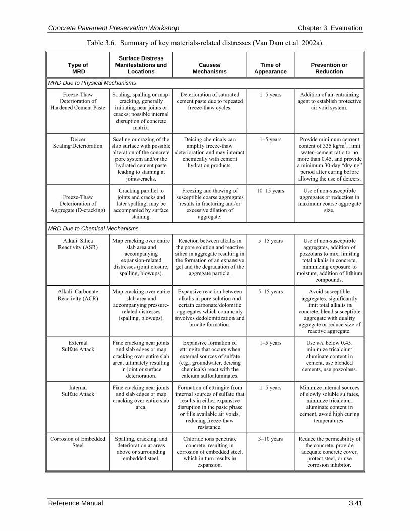
Concrete Pavement Preservation Workshop Chapter 3. Evaluation
Reference Manual 3.41
Table 3.6. Summary of key materials-related distresses (Van Dam et al. 2002a).
Type of MRD
Surface Distress Manifestations and
Locations
Causes/
Mechanisms
Time of
Appearance
Prevention or
Reduction
MRD Due to Physical Mechanisms
Freeze-Thaw Deterioration of
Hardened Cement Paste
Scaling, spalling or map-cracking, generally
initiating near joints or cracks; possible internal disruption of concrete
matrix.
Deterioration of saturated cement paste due to repeated
freeze-thaw cycles.
1–5 years Addition of air-entraining agent to establish protective
air void system.
Deicer Scaling/Deterioration
Scaling or crazing of the slab surface with possible alteration of the concrete pore system and/or the hydrated cement paste leading to staining at
joints/cracks.
Deicing chemicals can amplify freeze-thaw
deterioration and may interact chemically with cement
hydration products.
1–5 years Provide minimum cement content of 335 kg/m3, limit water–cement ratio to no
more than 0.45, and provide a minimum 30-day “drying”
period after curing before allowing the use of deicers.
Freeze-Thaw
Deterioration of Aggregate (D-cracking)
Cracking parallel to joints and cracks and later spalling; may be
accompanied by surface staining.
Freezing and thawing of susceptible coarse aggregates
results in fracturing and/or excessive dilation of
aggregate.
10–15 years Use of non-susceptible aggregates or reduction in
maximum coarse aggregate size.
MRD Due to Chemical Mechanisms
Alkali–Silica Reactivity (ASR)
Map cracking over entire slab area and
accompanying expansion-related
distresses (joint closure, spalling, blowups).
Reaction between alkalis in the pore solution and reactive silica in aggregate resulting in the formation of an expansive gel and the degradation of the
aggregate particle.
5–15 years Use of non-susceptible aggregates, addition of
pozzolans to mix, limiting total alkalis in concrete, minimizing exposure to
moisture, addition of lithium compounds.
Alkali–Carbonate Reactivity (ACR)
Map cracking over entire slab area and
accompanying pressure-related distresses
(spalling, blowups).
Expansive reaction between alkalis in pore solution and certain carbonate/dolomitic
aggregates which commonly involves dedolomitization and
brucite formation.
5–15 years Avoid susceptible aggregates, significantly
limit total alkalis in concrete, blend susceptible
aggregate with quality aggregate or reduce size of
reactive aggregate.
External Sulfate Attack
Fine cracking near joints and slab edges or map
cracking over entire slab area, ultimately resulting
in joint or surface deterioration.
Expansive formation of ettringite that occurs when external sources of sulfate (e.g., groundwater, deicing chemicals) react with the calcium sulfoaluminates.
1–5 years Use w/c below 0.45, minimize tricalcium aluminate content in cement, use blended
cements, use pozzolans.
Internal Sulfate Attack
Fine cracking near joints and slab edges or map
cracking over entire slab area.
Formation of ettringite from internal sources of sulfate that
results in either expansive disruption in the paste phase or fills available air voids,
reducing freeze-thaw resistance.
1–5 years Minimize internal sources of slowly soluble sulfates,
minimize tricalcium aluminate content in
cement, avoid high curing temperatures.
Corrosion of Embedded Steel
Spalling, cracking, and deterioration at areas above or surrounding
embedded steel.
Chloride ions penetrate concrete, resulting in
corrosion of embedded steel, which in turn results in
expansion.
3–10 years Reduce the permeability of the concrete, provide
adequate concrete cover, protect steel, or use corrosion inhibitor.
Chapter 3. Evaluation Concrete Pavement Preservation Workshop
3.42 Reference Manual
Drainage surveys are performed as part of a pavement distress survey in order to assess the overall drainage conditions of the existing pavement. This is because poor drainage conditions have long been recognized as a major cause of distress in pavement structures, and unless moisture-related problems are identified and corrected where possible, the effectiveness of any treatment will be reduced. A number of other field testing procedures are available for evaluating an existing pavement, although they may not commonly be needed for candidate pavement preservation projects. These procedures include deflection testing, smoothness and friction testing, and field sampling and testing. Deflection testing is often conducted as part of a pavement evaluation program to assess the uniformity and structural adequacy of existing pavements. For concrete pavements, deflection data can be analyzed to provide a wealth of information about the existing pavement structure, including the concrete elastic modulus and modulus of subgrade reaction (k-value), seasonal variations in these values, load transfer efficiencies, and the presence of voids under slab corners and edges. Over the years a variety of deflection testing equipment has been used, with the falling weight deflectometer (FWD) established as the current worldwide standard. In addition to determining a pavement’s structural condition, it is also important to assess a pavement’s functional characteristics. Functional considerations are those pavement characteristics that identify how well the pavement is providing a smooth, safe ride to the traveling public. Measurable characteristics that give an indication of a pavement’s functional condition include roughness, surface friction, and surface texture. Common methods and equipment used to assess these functional characteristics are also included in this chapter. Finally, it may be necessary to conduct a more detailed investigation of the in-place materials within a pavement structure. This additional material property data is commonly used to calibrate/verify distress and deflection data, provide material information where NDT data is not available, and help determine the causes of any observed pavement deficiencies. Many of the more commonly used in situ field tests and laboratory test methods are described in this chapter. 10. REFERENCES American Association of State Highway and Transportation Officials (AASHTO). 1993. Guide for Design of Pavement Structures. American Association of State Highway and Transportation Officials, Washington, DC.
American Concrete Pavement Association (ACPA). 1997. The Concrete Pavement Restoration Guide. Technical Bulletin TB020P. American Concrete Pavement Association, Skokie, IL.
Anderson, D. A., R. S. Huebner, J. R. Reed, J. C. Warner, and J. J. Henry. 1998. Improved Surface Drainage of Pavements. Final Report, NCHRP Project 1-29. NCHRP Web Document 16. Transportation Research Board, Washington, DC.
Bay, J. A. and K. H. Stokoe, II. 1998. Development of a Rolling Dynamic Deflectometer for Continuous Deflection Testing of Pavements. Report FHWA/TX-99/1422-3F. Federal Highway Administration, Washington, DC.
Carey, W. N. and P. E. Irick. 1960. “The Pavement Serviceability-Performance Concept.” Highway Research Bulletin No. 250. Highway Research Board, Washington, DC.
Christopher, B. R. 2000. Maintenance of Highway Edgedrains. NCHRP Synthesis of Highway Practice 285. Transportation Research Board, Washington, DC.
Dahir, S. H. M. and W. L. Gramling. 1990. Wet-Pavement Safety Programs. Synthesis of Highway Practice 158. Transportation Research Board, Washington, DC.
Daleiden, J. F. 1998. Video Inspection of Highway Edgedrain Systems. FHWA-SA-98-044. Federal Highway Administration, Washington, DC.
Concrete Pavement Preservation Workshop Chapter 3. Evaluation
Reference Manual 3.43
Darter, M. I., K. T. Hall, and Chen-Ming Kuo. 1995. Support Under Portland Cement Concrete Pavements. NCHRP Report 372. Transportation Research Board, Washington, DC.
Federal Highway Administration (FHWA). 2003. Manual on Uniform Traffic Control Devices—2003 Edition. Federal Highway Administration, Washington, DC.
Federal Highway Administration (FHWA). 2006a. 2006 Status of the Nation’s Highways, Bridges and Transit: Conditions and Performance. Report to Congress. Federal Highway Administration, Washington, DC.
Federal Highway Administration (FHWA). 2006b. LTPP Manual for Falling Weight Deflectometer Measurements, Version 4.1. FHWA-HRT-06-132. Federal Highway Administration, McLean, VA.
Gillespie, T. D., S. M. Karamihas, S. D. Kohn, and. R. W. Perera. 1999. Guidelines for Longitudinal Pavement Profile Measurement. NCHRP Report 434. Transportation Research Board, Washington, DC.
Grogg, M. G., and J. W. Hall. 2004. “Measuring Pavement Deflection at 55 MPH.” Public Roads, Volume 67, No. 4. Federal Highway Administration. Washington, DC.
Gothié, M. 2000. “Megatexture Indicators Obtained by the Analysis of a Pavement Surface Profile Measured with a Non-Contact Sensor.” Proceedings, Fourth International Symposium on Pavement Surface Characteristics of Roads and Airfields. PIARC Technical Committee on Surface Characteristics, Nantes, France.
Hall, K. T. 1992. Backcalculation Solutions for Concrete Pavements. Report prepared for SHRP Contract P-020. Transportation Research Board, Washington, DC.
Hall, K. T., M. I. Darter, and C. Kuo. 1995. “Improved Methods for Selection of k Value for Concrete Pavement Design.” Transportation Research Record 1505. Transportation Research Board, Washington, DC.
Hall, K. T., M. I. Darter, T. E. Horner, and L. Khazanovich. 1997. LTPP Data Analysis Phase I: Validation of Guidelines for k-Value Selection and Concrete Pavement Performance. FHWA-RD-96-198. Federal Highway Administration. McLean, VA.
Henry, J. J. 2000. Evaluation of Pavement Friction Characteristics. Synthesis of Highway Practice No. 291. National Cooperative Highway Research Program, Transportation Research Board, Washington, DC.
Hibbs, B. O. and R. M. Larson. 1996. Tire Pavement Noise and Safety Performance, PCC Surface Texture Technical Working Group. FHWA-SA-96-068. Federal Highway Administration, Washington, DC.
Highway Research Board (HRB). 1962. The AASHO Road Test, Report 5, Pavement Research. Special Report 61E. Highway Research Board, Washington, DC.
Hoerner, T. E., K. D. Smith, H. T. Yu, D. G. Peshkin, and M. J. Wade. 2001. PCC Pavement Evaluation and Rehabilitation, Reference Manual. NHI Course #131062. National Highway Institute, Arlington, VA.
Khazanovich, L. 2000. “Dynamic Analysis of FWD Test Results for Rigid Pavements.” Nondestructive Testing of Pavements and Backcalculation of Moduli: Third Volume. STP 1375. American Society for Testing and Materials, West Conshohocken, PA.
Khazanovich, L., S. D. Tayabji and M. I. Darter. 2001. Backcalculation of Layer Parameters for LTPP Test Sections, Volume 1: Slab on Elastic Solid and Slab on Dense-Liquid Foundation Analysis of Rigid Pavements. FHWA-RD-00-086. Federal Highway Administration, McLean, VA.
Khazanovich, L. and A. Gotlif. 2003. Evaluation of Joint and Crack Load Transfer―Final Report. FHWA-RD-02-088. Federal Highway Administration, McLean, VA.
Kulhawy, F. H. and P. W. Mayne. 1990. Manual on Estimating Soil Properties for Foundation Design. Report EL-6800. Electric Power Research Institute, Palo Alto, CA.
Chapter 3. Evaluation Concrete Pavement Preservation Workshop
3.44 Reference Manual
Laguros, J. G. and G. A. Miller. 1997. Stabilization of Existing Subgrades to Improve Constructability During Interstate Pavement Reconstruction. Synthesis of Highway Practice 247. National Cooperative Highway Research Program, Transportation Research Board, Washington, DC.
Larson, R. M., L. Scofield, and J. Sorenson. 2005. “Providing Durable, Safe, and Quiet Highways.” Proceedings, 8th International Conference on Concrete Pavements, Denver, CO.
Mallela, J., G. Larson, T. Wyatt, J. Hall, W. Barker. 2002. User’s Guide for Drainage Requirements in Pavements—DRIP 2.0 Microcomputer Program. Federal Highway Administration, Washington, DC.
Miller, J. S. and W. Y. Bellinger. 2003. Distress Identification Manual for the Long-Term Pavement Performance Program (Fourth Revised Edition). FHWA-RD-03-031. Federal Highway Administration, McLean, VA.
Mindess, S. and J. F. Young. 1981. Concrete. Prentice-Hall, Inc., Englewood Cliffs, NJ.
National Cooperative Highway Research Program (NCHRP). 2004. Guide for Mechanistic-Empirical Design of New and Rehabilitated Pavement Structures. Final Report. Transportation Research Board, Washington, DC.
Neville, A. M. 1996. Properties of Concrete. Fourth and Final Edition. John Wiley and Sons, Inc. New York, NY.
Newcomb, D. E. and B. Birgisson. 1999. Measuring In Situ Mechanical Properties of Pavement Subgrade Soils. Synthesis of Highway Practice 278. National Cooperative Highway Research Program, Transportation Research Board, Washington, DC.
Oglesby, C. H. and G. L. Hicks. 1982. Highway Engineering. John Wiley & Sons, New York, NY.
Paterson, W. D. O. 1987. “International Roughness Index: Relationship to Other Measures of Roughness and Riding Quality.” Transportation Research Record 1084. Transportation Research Board, Washington, DC.
Portland Cement Association (PCA). 1992. PCA Soil Primer. EB-007.05S. Portland Cement Association, Skokie, IL.
Sayers, M. W. 1985. “Development, Implementation, and Application of the Reference Quarter-Car Simulation.” ASTM Special Technical Publication 884. American Society for Testing and Materials, Philadelphia, PA.
Sayers, M. W. 1990. “Profiles of Roughness.” Transportation Research Record 1260. Transportation Research Board, Washington, DC.
Sayers, M. W. and S. M. Karamihas. 1998. The Little Book of Profiling—Basic Information about Measuring and Interpreting Road Profiles. University of Michigan Transportation Research Institute, Ann Arbor, MI. Web address: www.umtri.umich.edu/erd/roughness.
Shahin, M. Y. 1994. Pavement Management for Airports, Roads, and Parking Lots. Chapman and Hall, New York, NY.
Shahin, M. Y. and J. A. Walther. 1990. Pavement Maintenance Management for Roads and Streets Using the PAVER System. Technical Report M-90/05. U.S. Army Corps of Engineers, Washington, DC.
Smith, K. L., K. D. Smith, L. D. Evans, T. E. Hoerner, and M. I. Darter. 1997. Smoothness Specifications for Pavements. Web Document #1, Final Report NCHRP Project 1-31. Transportation Research Board, Washington, DC.
Snyder, M. B. 2006. Pavement Surface Characteristics: A Synthesis and Guide. EB235P. American Concrete Pavement Association, Skokie, IL.
United States Army Engineer Waterways Experimental Station (US Army). 1989. Instruction Manual, Dynamic Cone Penetrometer. U.S. Army Engineer Waterways Experimental Station, Vicksburg, MS.

Concrete Pavement Preservation Workshop Chapter 3. Evaluation
Reference Manual 3.45
Van Dam, T. J., L. L. Sutter, K. D. Smith, M. J. Wade, and K. R. Peterson. 2002a. Guidelines for Detection, Analysis, and Treatment of Materials-Related Distress in Concrete Pavements, Volume 1: Final Report. FHWA-RD-01-163. Federal Highway Administration, McLean, VA.
Van Dam, T. J., L. L. Sutter, K. D. Smith, M. J. Wade, and K. R. Peterson. 2002b. Guidelines for Detection, Analysis, and Treatment of Materials-Related Distress in Concrete Pavements, Volume 2: Guidelines Description and Use. FHWA-RD-01-164. Federal Highway Administration, McLean, VA.
Webster, S. L., R. H. Grau, and T. P. Williams. 1992. Description and Application of Dual Mass Dynamic Cone Penetrometer. Instruction Report GL-92-3. U.S. Army Engineer Waterways Experiment Station, Vicksburg, MS.
Webster, S. L., R. W. Brown, and J. R. Porter. 1994. Force Projection Site Evaluation Using the Electric Cone Penetrometer (ECP) and the Dynamic Cone Penetrometer (DCP). Technical Report GL-94-17. U.S. Air Force, Tyndall AFB, Florida.

Chapter 3. Evaluation Concrete Pavement Preservation Workshop
3.46 Reference Manual
NOTES
Concrete Pavement Preservation Workshop Chapter 4. Slab Stabilization
Reference Manual 4.1
CHAPTER 4. SLAB STABILIZATION AND SLAB JACKING 1. LEARNING OUTCOMES This chapter covers the use of two different pavement preservation treatments: slab stabilization (also known as undersealing), which is performed to restore support beneath concrete slabs, and slab jacking, which is conducted to physically lift a depressed slab back to the elevation of adjacent slabs. The participants will be able to accomplish the following upon successful completion of this chapter:
1. List benefits of slab stabilization and slab jacking.
2. Describe recommended materials and mixtures.
3. Identify recommended construction activities.
4. Identify typical construction problems and remedies.
2. INTRODUCTION Pumping and loss of support occurs beneath concrete pavements due to the presence of three factors: an erodible base or subbase, excessive moisture, and significant slab deflections. Poor support conditions can lead to faulting and corner breaks, and can be a major contributor to the accelerated deterioration of the pavement. Slab stabilization has been used to restore support to slabs by filling voids, thereby reducing deflections and retarding the development of additional pavement deterioration. Settlements sometimes occur on PCC pavements in areas of poor foundation support. Such settlements not only provide riding discomfort, they also can create large stresses in the slab that can lead to cracking. In some cases, these slabs can be raised back to their original elevation by pressure inserting a material beneath the settled slabs and raising them back to the desired elevation. This process of raising slabs is referred to as slab jacking. 3. PURPOSE AND PROJECT SELECTION Slab stabilization should be performed only at joints and working cracks where loss of support is known to exist. Stabilizing slabs where loss of support does not exist is not only wasteful, it may even be detrimental to pavement performance (Crovetti and Darter 1985; Wu 1991). To be most effective, it is important that slab stabilization be performed prior to the onset of pavement damage due to loss of support (Wu 1991; ACPA 1994). However, because loss of support is caused by several factors, slab stabilization alone is not sufficient to eliminate the problem; the underlying mechanisms themselves must also be addressed in order to ensure the longevity of the treatment (ACPA 1994; Hoerner et al. 2001). As differentiated from slab stabilization, slab jacking consists of the pressure insertion of a grout or polyurethane material beneath the slab to slowly raise the slab until it reaches a smooth profile. Ideal projects for slab jacking are pavements that exhibit localized areas of settlement. Settlements can occur anywhere along a pavement profile, but most usually are associated with fill areas, over culverts, and at bridge approaches. Slab jacking is not recommended for repairing faulted joints, as this is more effectively addressed through diamond grinding. 4. LIMITATIONS AND EFFECTIVENESS Slab Stabilization Over the years, a number of state highway agencies have experienced mixed results with slab stabilization. One of the biggest issues has been the ability to accurately identify the presence of voids beneath the slab. When slab stabilization has been conducted where no voids exist, the pumping of the material beneath the slab can induce stress points and actually increase the rate of pavement deterioration.
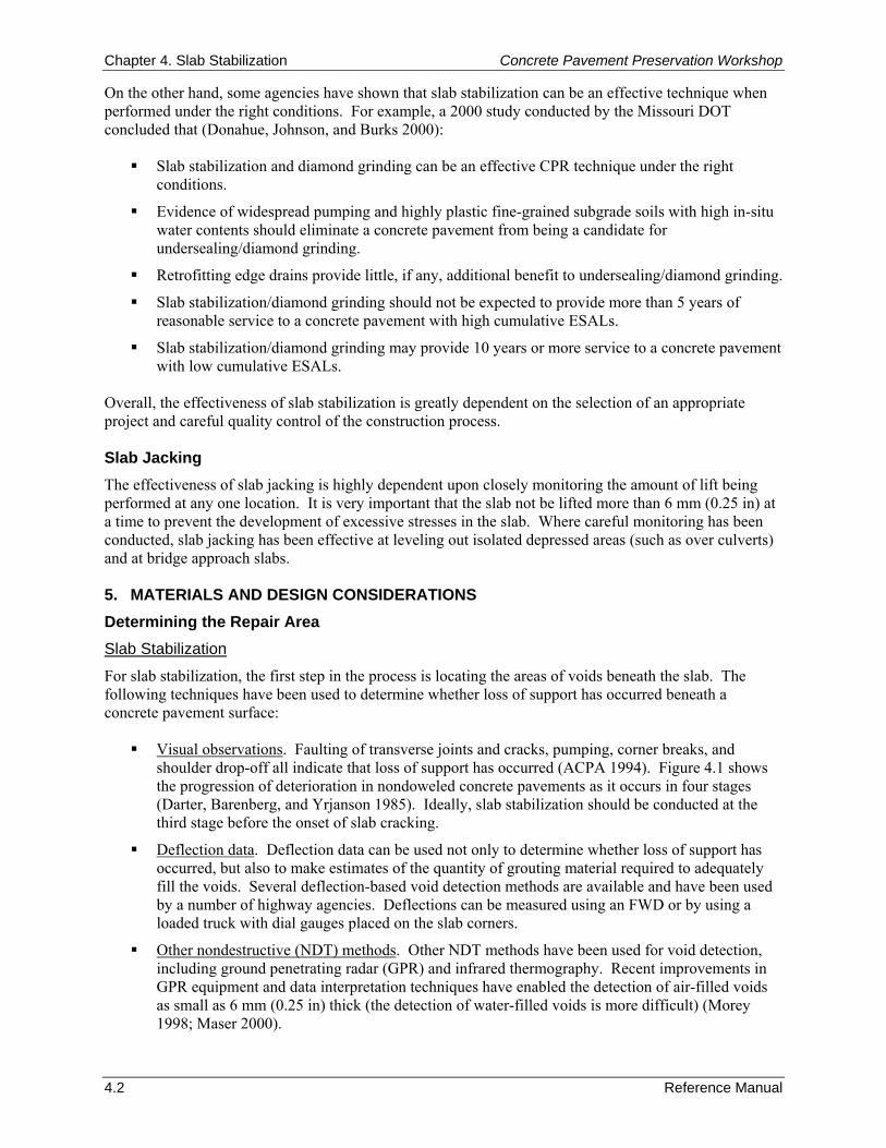
Chapter 4. Slab Stabilization Concrete Pavement Preservation Workshop
4.2 Reference Manual
On the other hand, some agencies have shown that slab stabilization can be an effective technique when performed under the right conditions. For example, a 2000 study conducted by the Missouri DOT concluded that (Donahue, Johnson, and Burks 2000):
Slab stabilization and diamond grinding can be an effective CPR technique under the right conditions.
Evidence of widespread pumping and highly plastic fine-grained subgrade soils with high in-situ water contents should eliminate a concrete pavement from being a candidate for undersealing/diamond grinding.
Retrofitting edge drains provide little, if any, additional benefit to undersealing/diamond grinding.
Slab stabilization/diamond grinding should not be expected to provide more than 5 years of reasonable service to a concrete pavement with high cumulative ESALs.
Slab stabilization/diamond grinding may provide 10 years or more service to a concrete pavement with low cumulative ESALs.
Overall, the effectiveness of slab stabilization is greatly dependent on the selection of an appropriate project and careful quality control of the construction process. Slab Jacking The effectiveness of slab jacking is highly dependent upon closely monitoring the amount of lift being performed at any one location. It is very important that the slab not be lifted more than 6 mm (0.25 in) at a time to prevent the development of excessive stresses in the slab. Where careful monitoring has been conducted, slab jacking has been effective at leveling out isolated depressed areas (such as over culverts) and at bridge approach slabs. 5. MATERIALS AND DESIGN CONSIDERATIONS Determining the Repair Area Slab Stabilization
For slab stabilization, the first step in the process is locating the areas of voids beneath the slab. The following techniques have been used to determine whether loss of support has occurred beneath a concrete pavement surface:
Visual observations. Faulting of transverse joints and cracks, pumping, corner breaks, and shoulder drop-off all indicate that loss of support has occurred (ACPA 1994). Figure 4.1 shows the progression of deterioration in nondoweled concrete pavements as it occurs in four stages (Darter, Barenberg, and Yrjanson 1985). Ideally, slab stabilization should be conducted at the third stage before the onset of slab cracking.
Deflection data. Deflection data can be used not only to determine whether loss of support has occurred, but also to make estimates of the quantity of grouting material required to adequately fill the voids. Several deflection-based void detection methods are available and have been used by a number of highway agencies. Deflections can be measured using an FWD or by using a loaded truck with dial gauges placed on the slab corners.
Other nondestructive (NDT) methods. Other NDT methods have been used for void detection, including ground penetrating radar (GPR) and infrared thermography. Recent improvements in GPR equipment and data interpretation techniques have enabled the detection of air-filled voids as small as 6 mm (0.25 in) thick (the detection of water-filled voids is more difficult) (Morey 1998; Maser 2000).
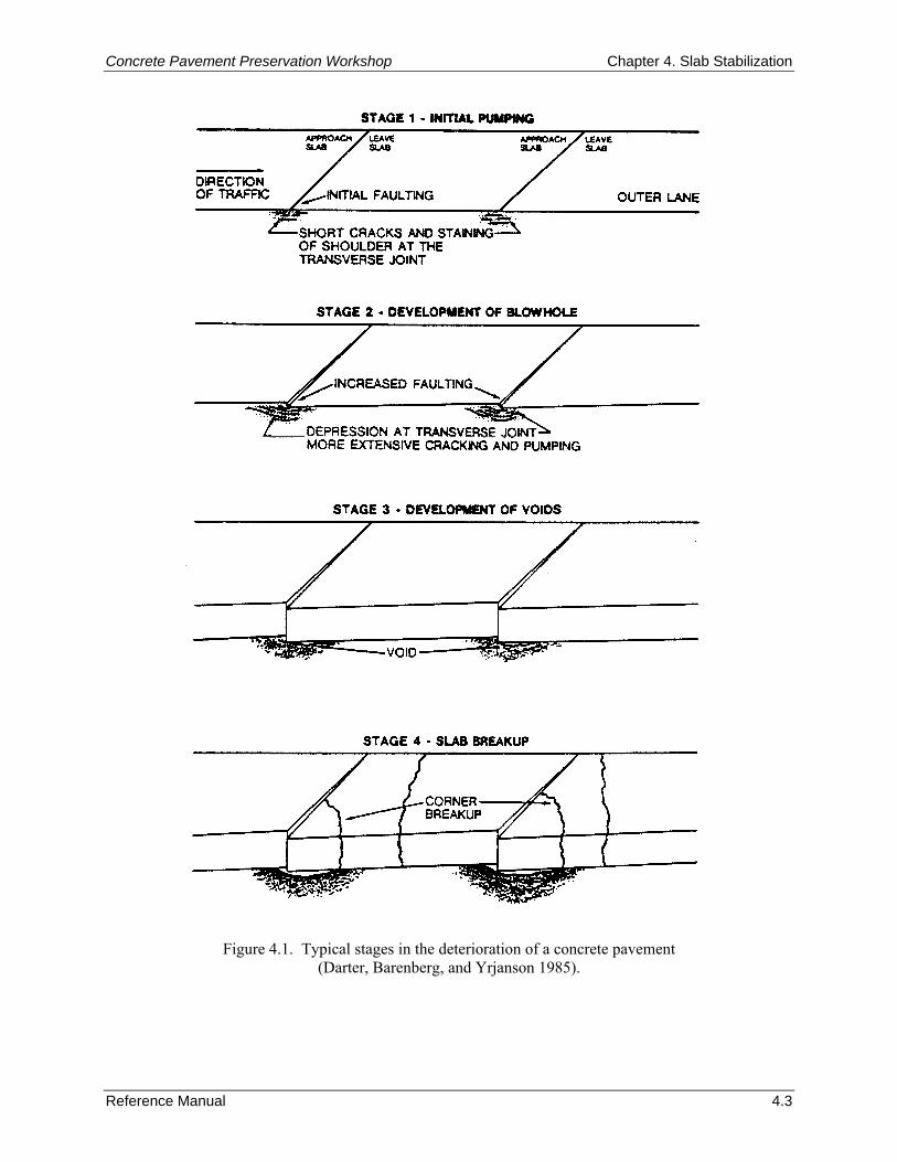
Concrete Pavement Preservation Workshop Chapter 4. Slab Stabilization
Reference Manual 4.3
Figure 4.1. Typical stages in the deterioration of a concrete pavement
(Darter, Barenberg, and Yrjanson 1985).
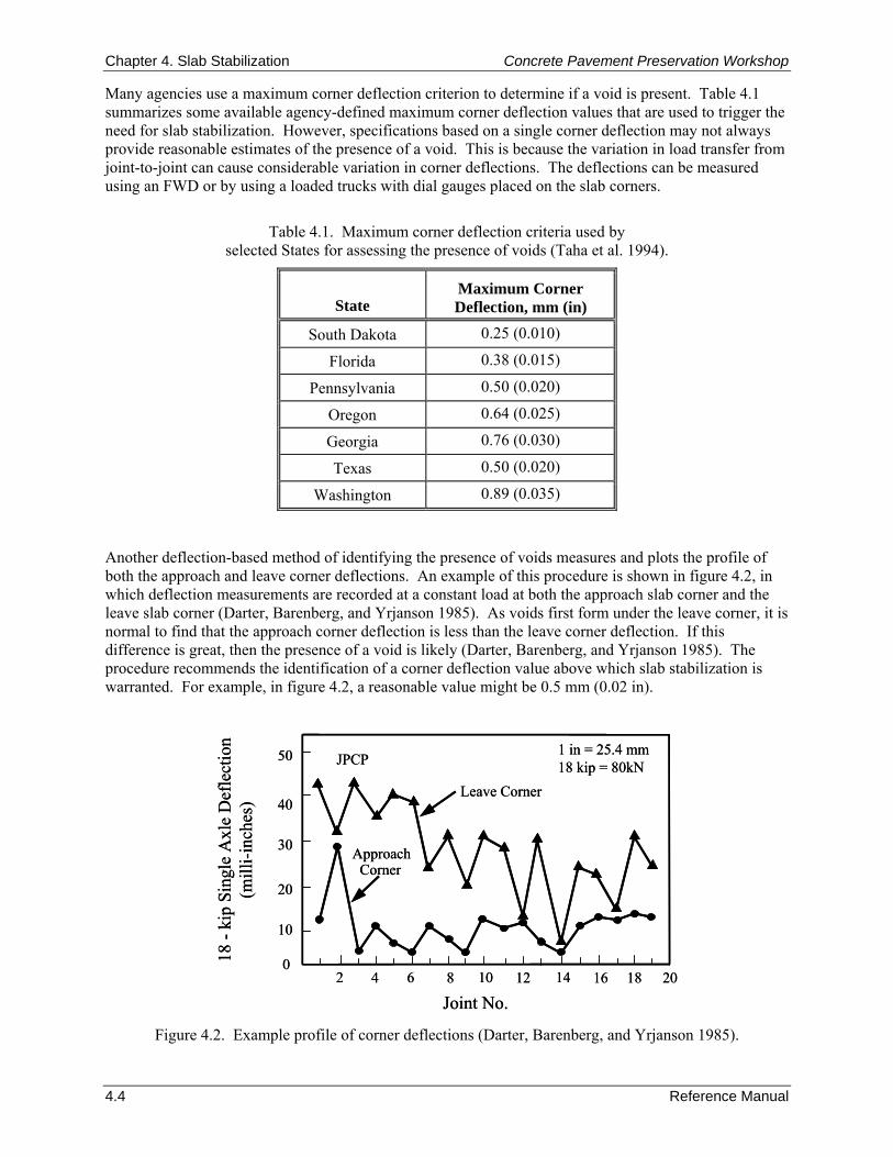
Chapter 4. Slab Stabilization Concrete Pavement Preservation Workshop
4.4 Reference Manual
Many agencies use a maximum corner deflection criterion to determine if a void is present. Table 4.1 summarizes some available agency-defined maximum corner deflection values that are used to trigger the need for slab stabilization. However, specifications based on a single corner deflection may not always provide reasonable estimates of the presence of a void. This is because the variation in load transfer from joint-to-joint can cause considerable variation in corner deflections. The deflections can be measured using an FWD or by using a loaded trucks with dial gauges placed on the slab corners.
Table 4.1. Maximum corner deflection criteria used by selected States for assessing the presence of voids (Taha et al. 1994).
State
Maximum Corner Deflection, mm (in)
South Dakota 0.25 (0.010)
Florida 0.38 (0.015)
Pennsylvania 0.50 (0.020)
Oregon 0.64 (0.025)
Georgia 0.76 (0.030)
Texas 0.50 (0.020)
Washington 0.89 (0.035)
Another deflection-based method of identifying the presence of voids measures and plots the profile of both the approach and leave corner deflections. An example of this procedure is shown in figure 4.2, in which deflection measurements are recorded at a constant load at both the approach slab corner and the leave slab corner (Darter, Barenberg, and Yrjanson 1985). As voids first form under the leave corner, it is normal to find that the approach corner deflection is less than the leave corner deflection. If this difference is great, then the presence of a void is likely (Darter, Barenberg, and Yrjanson 1985). The procedure recommends the identification of a corner deflection value above which slab stabilization is warranted. For example, in figure 4.2, a reasonable value might be 0.5 mm (0.02 in).
Joint No.
18 -
kip
Sing
le A
xle
Def
lect
ion
(mill
i-inc
hes)
2
1 in = 25.4 mm 18 kip = 80kN
Leave Corner
ApproachCorner
JPCP
4 6 8 10 12 14 16 18 20
10
0
20
30
40
50
Joint No.
18 -
kip
Sing
le A
xle
Def
lect
ion
(mill
i-inc
hes)
2
1 in = 25.4 mm 18 kip = 80kN
Leave Corner
ApproachCorner
JPCP
4 6 8 10 12 14 16 18 20
10
0
20
30
40
50
Figure 4.2. Example profile of corner deflections (Darter, Barenberg, and Yrjanson 1985).
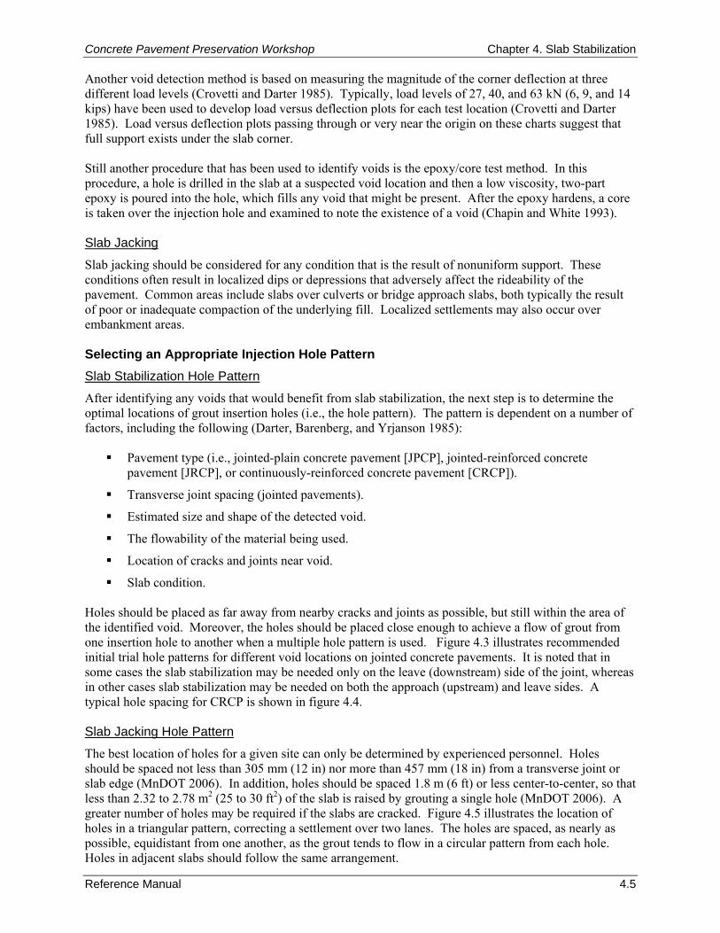
Concrete Pavement Preservation Workshop Chapter 4. Slab Stabilization
Reference Manual 4.5
Another void detection method is based on measuring the magnitude of the corner deflection at three different load levels (Crovetti and Darter 1985). Typically, load levels of 27, 40, and 63 kN (6, 9, and 14 kips) have been used to develop load versus deflection plots for each test location (Crovetti and Darter 1985). Load versus deflection plots passing through or very near the origin on these charts suggest that full support exists under the slab corner. Still another procedure that has been used to identify voids is the epoxy/core test method. In this procedure, a hole is drilled in the slab at a suspected void location and then a low viscosity, two-part epoxy is poured into the hole, which fills any void that might be present. After the epoxy hardens, a core is taken over the injection hole and examined to note the existence of a void (Chapin and White 1993). Slab Jacking
Slab jacking should be considered for any condition that is the result of nonuniform support. These conditions often result in localized dips or depressions that adversely affect the rideability of the pavement. Common areas include slabs over culverts or bridge approach slabs, both typically the result of poor or inadequate compaction of the underlying fill. Localized settlements may also occur over embankment areas. Selecting an Appropriate Injection Hole Pattern Slab Stabilization Hole Pattern
After identifying any voids that would benefit from slab stabilization, the next step is to determine the optimal locations of grout insertion holes (i.e., the hole pattern). The pattern is dependent on a number of factors, including the following (Darter, Barenberg, and Yrjanson 1985):
Pavement type (i.e., jointed-plain concrete pavement [JPCP], jointed-reinforced concrete pavement [JRCP], or continuously-reinforced concrete pavement [CRCP]).
Transverse joint spacing (jointed pavements).
Estimated size and shape of the detected void.
The flowability of the material being used.
Location of cracks and joints near void.
Slab condition. Holes should be placed as far away from nearby cracks and joints as possible, but still within the area of the identified void. Moreover, the holes should be placed close enough to achieve a flow of grout from one insertion hole to another when a multiple hole pattern is used. Figure 4.3 illustrates recommended initial trial hole patterns for different void locations on jointed concrete pavements. It is noted that in some cases the slab stabilization may be needed only on the leave (downstream) side of the joint, whereas in other cases slab stabilization may be needed on both the approach (upstream) and leave sides. A typical hole spacing for CRCP is shown in figure 4.4. Slab Jacking Hole Pattern
The best location of holes for a given site can only be determined by experienced personnel. Holes should be spaced not less than 305 mm (12 in) nor more than 457 mm (18 in) from a transverse joint or slab edge (MnDOT 2006). In addition, holes should be spaced 1.8 m (6 ft) or less center-to-center, so that less than 2.32 to 2.78 m2 (25 to 30 ft2) of the slab is raised by grouting a single hole (MnDOT 2006). A greater number of holes may be required if the slabs are cracked. Figure 4.5 illustrates the location of holes in a triangular pattern, correcting a settlement over two lanes. The holes are spaced, as nearly as possible, equidistant from one another, as the grout tends to flow in a circular pattern from each hole. Holes in adjacent slabs should follow the same arrangement.
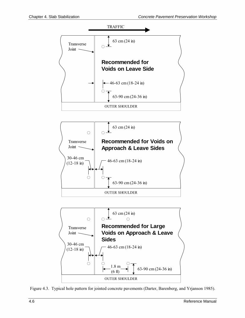
Chapter 4. Slab Stabilization Concrete Pavement Preservation Workshop
4.6 Reference Manual
63-90 cm (24-36 in)
46-63 cm (18-24 in)
OUTER SHOULDER
Recommended forVoids on Leave Side
63 cm (24 in)
TRAFFIC
TransverseJoint
63-90 cm (24-36 in)
46-63 cm (18-24 in)
OUTER SHOULDER
Recommended for Voids onApproach & Leave Sides
63 cm (24 in)
TransverseJoint
30-46 cm(12-18 in)
63-90 cm (24-36 in)
46-63 cm (18-24 in)
OUTER SHOULDER
Recommended for LargeVoids on Approach & LeaveSides
63 cm (24 in)
TransverseJoint
30-46 cm(12-18 in)
1.8 m(6 ft)
Figure 4.3. Typical hole pattern for jointed concrete pavements (Darter, Barenberg, and Yrjanson 1985).
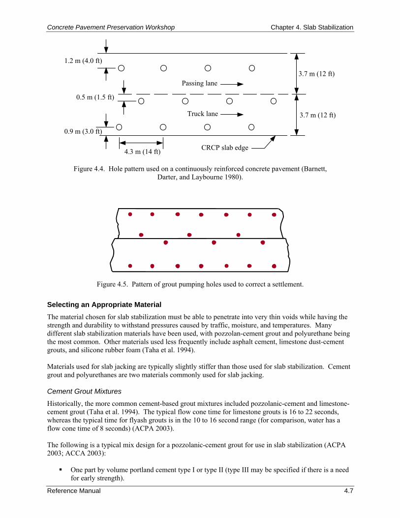
Concrete Pavement Preservation Workshop Chapter 4. Slab Stabilization
Reference Manual 4.7
4.3 m (14 ft)
0.9 m (3.0 ft)
0.5 m (1.5 ft)
Passing lane
Truck lane
1.2 m (4.0 ft)
3.7 m (12 ft)
3.7 m (12 ft)
CRCP slab edge
Figure 4.4. Hole pattern used on a continuously reinforced concrete pavement (Barnett,
Darter, and Laybourne 1980).
Figure 4.5. Pattern of grout pumping holes used to correct a settlement.
Selecting an Appropriate Material The material chosen for slab stabilization must be able to penetrate into very thin voids while having the strength and durability to withstand pressures caused by traffic, moisture, and temperatures. Many different slab stabilization materials have been used, with pozzolan-cement grout and polyurethane being the most common. Other materials used less frequently include asphalt cement, limestone dust-cement grouts, and silicone rubber foam (Taha et al. 1994). Materials used for slab jacking are typically slightly stiffer than those used for slab stabilization. Cement grout and polyurethanes are two materials commonly used for slab jacking. Cement Grout Mixtures
Historically, the more common cement-based grout mixtures included pozzolanic-cement and limestone-cement grout (Taha et al. 1994). The typical flow cone time for limestone grouts is 16 to 22 seconds, whereas the typical time for flyash grouts is in the 10 to 16 second range (for comparison, water has a flow cone time of 8 seconds) (ACPA 2003). The following is a typical mix design for a pozzolanic-cement grout for use in slab stabilization (ACPA 2003; ACCA 2003):
One part by volume portland cement type I or type II (type III may be specified if there is a need for early strength).
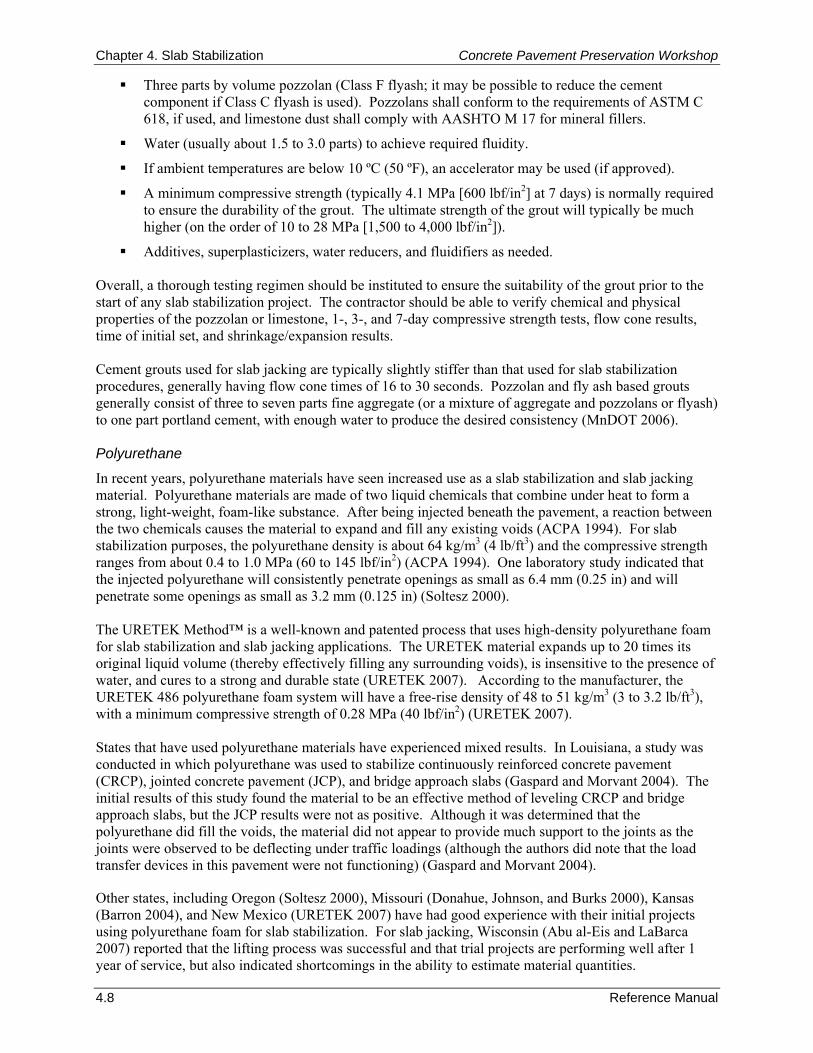
Chapter 4. Slab Stabilization Concrete Pavement Preservation Workshop
4.8 Reference Manual
Three parts by volume pozzolan (Class F flyash; it may be possible to reduce the cement component if Class C flyash is used). Pozzolans shall conform to the requirements of ASTM C 618, if used, and limestone dust shall comply with AASHTO M 17 for mineral fillers.
Water (usually about 1.5 to 3.0 parts) to achieve required fluidity.
If ambient temperatures are below 10 ºC (50 ºF), an accelerator may be used (if approved).
A minimum compressive strength (typically 4.1 MPa [600 lbf/in2] at 7 days) is normally required to ensure the durability of the grout. The ultimate strength of the grout will typically be much higher (on the order of 10 to 28 MPa [1,500 to 4,000 lbf/in2]).
Additives, superplasticizers, water reducers, and fluidifiers as needed. Overall, a thorough testing regimen should be instituted to ensure the suitability of the grout prior to the start of any slab stabilization project. The contractor should be able to verify chemical and physical properties of the pozzolan or limestone, 1-, 3-, and 7-day compressive strength tests, flow cone results, time of initial set, and shrinkage/expansion results. Cement grouts used for slab jacking are typically slightly stiffer than that used for slab stabilization procedures, generally having flow cone times of 16 to 30 seconds. Pozzolan and fly ash based grouts generally consist of three to seven parts fine aggregate (or a mixture of aggregate and pozzolans or flyash) to one part portland cement, with enough water to produce the desired consistency (MnDOT 2006). Polyurethane
In recent years, polyurethane materials have seen increased use as a slab stabilization and slab jacking material. Polyurethane materials are made of two liquid chemicals that combine under heat to form a strong, light-weight, foam-like substance. After being injected beneath the pavement, a reaction between the two chemicals causes the material to expand and fill any existing voids (ACPA 1994). For slab stabilization purposes, the polyurethane density is about 64 kg/m3 (4 lb/ft3) and the compressive strength ranges from about 0.4 to 1.0 MPa (60 to 145 lbf/in2) (ACPA 1994). One laboratory study indicated that the injected polyurethane will consistently penetrate openings as small as 6.4 mm (0.25 in) and will penetrate some openings as small as 3.2 mm (0.125 in) (Soltesz 2000). The URETEK Method™ is a well-known and patented process that uses high-density polyurethane foam for slab stabilization and slab jacking applications. The URETEK material expands up to 20 times its original liquid volume (thereby effectively filling any surrounding voids), is insensitive to the presence of water, and cures to a strong and durable state (URETEK 2007). According to the manufacturer, the URETEK 486 polyurethane foam system will have a free-rise density of 48 to 51 kg/m3 (3 to 3.2 lb/ft3), with a minimum compressive strength of 0.28 MPa (40 lbf/in2) (URETEK 2007). States that have used polyurethane materials have experienced mixed results. In Louisiana, a study was conducted in which polyurethane was used to stabilize continuously reinforced concrete pavement (CRCP), jointed concrete pavement (JCP), and bridge approach slabs (Gaspard and Morvant 2004). The initial results of this study found the material to be an effective method of leveling CRCP and bridge approach slabs, but the JCP results were not as positive. Although it was determined that the polyurethane did fill the voids, the material did not appear to provide much support to the joints as the joints were observed to be deflecting under traffic loadings (although the authors did note that the load transfer devices in this pavement were not functioning) (Gaspard and Morvant 2004).
Other states, including Oregon (Soltesz 2000), Missouri (Donahue, Johnson, and Burks 2000), Kansas (Barron 2004), and New Mexico (URETEK 2007) have had good experience with their initial projects using polyurethane foam for slab stabilization. For slab jacking, Wisconsin (Abu al-Eis and LaBarca 2007) reported that the lifting process was successful and that trial projects are performing well after 1 year of service, but also indicated shortcomings in the ability to estimate material quantities.
Concrete Pavement Preservation Workshop Chapter 4. Slab Stabilization
Reference Manual 4.9
6. CONSTRUCTION CONSIDERATIONS Slab Stabilization Step 1: Drilling of Injection Holes
Any hand-held or mechanical drill that produces clean holes with no surface spalling or breakouts on the underside of the slab is acceptable for creating the injection holes (ACPA 1994). Specifically, for portland cement-based grout projects, any pneumatic or hydraulic rotary percussion drill that is capable of cutting 38-to 51-mm (1.25- to 2.0-in) diameter holes through the slab are suitable. A general specification recommends limiting the downward pressure on any drill to 90 kg (200 lb) to avoid conical spalling at the bottom of the slab (ACPA 1994). When large pieces of the underside of the slab spall, these pieces can potentially block the void and make it impossible to fill. For polyurethane slab stabilization, hand-held electric-pneumatic rock drills are typically used to drill the injection holes (ACPA 1994). For these procedures, the maximum hole diameter should not exceed 15 mm (0.625 in) (ACPA 1994). A quick check of whether or not the hole should be grouted may be made by pouring water into the drill hole (note that the water does not create a problem as it is displaced when grout is pumped into the hole). If the hole does not take water, there is no void and therefore no need to grout. When it is determined that there is no void, the hole can be filled with an acceptable patching material and the operation can proceed to the next hole. While the typical injection hole pattern is determined during the design process, the location of the injection holes may need to be adjusted in the field in order to effectively fill each void. If the flow is easily achieved, the hole spacing may be increased. Conversely, if good flow is not achieved before maximum back pressure is reached, the hole spacing should be reduced. Step 2: Material Preparation
Most slab stabilization contractors use mobile, self contained equipment that carries all of the tools and materials needed for slab stabilization (ACPA 1994). As past procedures typically utilized labor-intensive, small batch mixers with bagged materials, these modern systems have been found to reduce both labor and materials costs by as much as 30 to 50 percent (ACPA 1994). The differences in preparing cement-based and polyurethane materials are discussed in this section. Cement Grout Mixtures
For cement-grout mixtures, a grout plant that is capable of accurately measuring, proportioning, and mixing the material by volume or weight is used. When working with pozzolan-cement grouts, it is recommended that contractors use colloidal mixing equipment. Colloidal mixers provide the most thorough mixing for pozzolan-cement grouts, as the material stays in suspension and resists dilution by free water (ACPA 1994). Two of the more common types of colloidal mixers include (ACPA 1994):
Centrifugal pump mixer. This mixer pulls grout through a mixing chamber at high pressure and velocity.
Shear blade mixer. For this mixer type, blades rotate at 800 to 2,000 revolutions per minute. Whenever possible, contractors should avoid using paddle-type drum mixers with cement-pozzolan grouts (ACPA 1994). This is because the low agitation of these mixers makes it very difficult to thoroughly mix the grout. Paddle-drum mixers are, however, effective at thoroughly mixing limestone dust grouts (AASHTO 1993). Conveyors, mortar mixers, or ready-mix trucks should not be used to mix any type of stabilization material as these mixers require adding too much water for fluidity and the solids tend to agglomerate and clump in the mix (ACPA 1994).
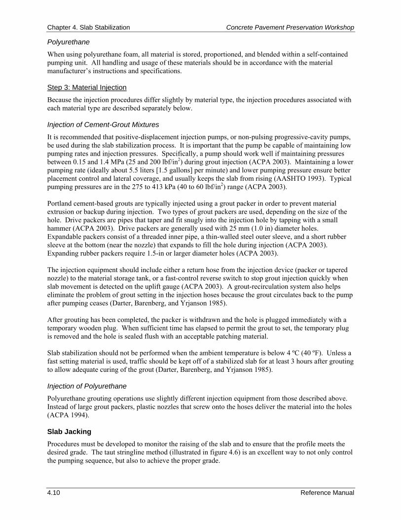
Chapter 4. Slab Stabilization Concrete Pavement Preservation Workshop
4.10 Reference Manual
Polyurethane
When using polyurethane foam, all material is stored, proportioned, and blended within a self-contained pumping unit. All handling and usage of these materials should be in accordance with the material manufacturer’s instructions and specifications. Step 3: Material Injection
Because the injection procedures differ slightly by material type, the injection procedures associated with each material type are described separately below. Injection of Cement-Grout Mixtures
It is recommended that positive-displacement injection pumps, or non-pulsing progressive-cavity pumps, be used during the slab stabilization process. It is important that the pump be capable of maintaining low pumping rates and injection pressures. Specifically, a pump should work well if maintaining pressures between 0.15 and 1.4 MPa (25 and 200 lbf/in2) during grout injection (ACPA 2003). Maintaining a lower pumping rate (ideally about 5.5 liters [1.5 gallons] per minute) and lower pumping pressure ensure better placement control and lateral coverage, and usually keeps the slab from rising (AASHTO 1993). Typical pumping pressures are in the 275 to 413 kPa (40 to 60 lbf/in2) range (ACPA 2003). Portland cement-based grouts are typically injected using a grout packer in order to prevent material extrusion or backup during injection. Two types of grout packers are used, depending on the size of the hole. Drive packers are pipes that taper and fit snugly into the injection hole by tapping with a small hammer (ACPA 2003). Drive packers are generally used with 25 mm (1.0 in) diameter holes. Expandable packers consist of a threaded inner pipe, a thin-walled steel outer sleeve, and a short rubber sleeve at the bottom (near the nozzle) that expands to fill the hole during injection (ACPA 2003). Expanding rubber packers require 1.5-in or larger diameter holes (ACPA 2003). The injection equipment should include either a return hose from the injection device (packer or tapered nozzle) to the material storage tank, or a fast-control reverse switch to stop grout injection quickly when slab movement is detected on the uplift gauge (ACPA 2003). A grout-recirculation system also helps eliminate the problem of grout setting in the injection hoses because the grout circulates back to the pump after pumping ceases (Darter, Barenberg, and Yrjanson 1985). After grouting has been completed, the packer is withdrawn and the hole is plugged immediately with a temporary wooden plug. When sufficient time has elapsed to permit the grout to set, the temporary plug is removed and the hole is sealed flush with an acceptable patching material. Slab stabilization should not be performed when the ambient temperature is below 4 ºC (40 ºF). Unless a fast setting material is used, traffic should be kept off of a stabilized slab for at least 3 hours after grouting to allow adequate curing of the grout (Darter, Barenberg, and Yrjanson 1985). Injection of Polyurethane
Polyurethane grouting operations use slightly different injection equipment from those described above. Instead of large grout packers, plastic nozzles that screw onto the hoses deliver the material into the holes (ACPA 1994). Slab Jacking Procedures must be developed to monitor the raising of the slab and to ensure that the profile meets the desired grade. The taut stringline method (illustrated in figure 4.6) is an excellent way to not only control the pumping sequence, but also to achieve the proper grade.
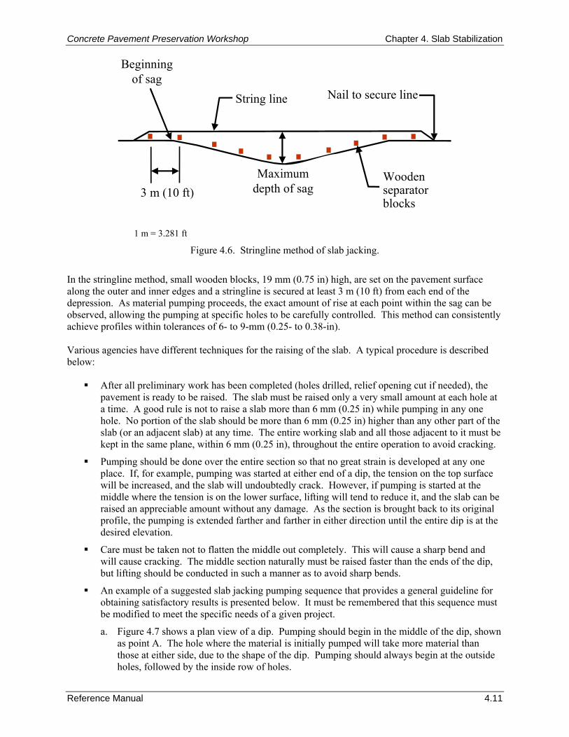
Concrete Pavement Preservation Workshop Chapter 4. Slab Stabilization
Reference Manual 4.11
Maximumdepth of sag
String line
Beginningof sag
3 m (10 ft)Woodenseparatorblocks
Nail to secure line
1 m = 3.281 ft
Figure 4.6. Stringline method of slab jacking.
In the stringline method, small wooden blocks, 19 mm (0.75 in) high, are set on the pavement surface along the outer and inner edges and a stringline is secured at least 3 m (10 ft) from each end of the depression. As material pumping proceeds, the exact amount of rise at each point within the sag can be observed, allowing the pumping at specific holes to be carefully controlled. This method can consistently achieve profiles within tolerances of 6- to 9-mm (0.25- to 0.38-in). Various agencies have different techniques for the raising of the slab. A typical procedure is described below:
After all preliminary work has been completed (holes drilled, relief opening cut if needed), the pavement is ready to be raised. The slab must be raised only a very small amount at each hole at a time. A good rule is not to raise a slab more than 6 mm (0.25 in) while pumping in any one hole. No portion of the slab should be more than 6 mm (0.25 in) higher than any other part of the slab (or an adjacent slab) at any time. The entire working slab and all those adjacent to it must be kept in the same plane, within 6 mm (0.25 in), throughout the entire operation to avoid cracking.
Pumping should be done over the entire section so that no great strain is developed at any one place. If, for example, pumping was started at either end of a dip, the tension on the top surface will be increased, and the slab will undoubtedly crack. However, if pumping is started at the middle where the tension is on the lower surface, lifting will tend to reduce it, and the slab can be raised an appreciable amount without any damage. As the section is brought back to its original profile, the pumping is extended farther and farther in either direction until the entire dip is at the desired elevation.
Care must be taken not to flatten the middle out completely. This will cause a sharp bend and will cause cracking. The middle section naturally must be raised faster than the ends of the dip, but lifting should be conducted in such a manner as to avoid sharp bends.
An example of a suggested slab jacking pumping sequence that provides a general guideline for obtaining satisfactory results is presented below. It must be remembered that this sequence must be modified to meet the specific needs of a given project.
a. Figure 4.7 shows a plan view of a dip. Pumping should begin in the middle of the dip, shown as point A. The hole where the material is initially pumped will take more material than those at either side, due to the shape of the dip. Pumping should always begin at the outside holes, followed by the inside row of holes.
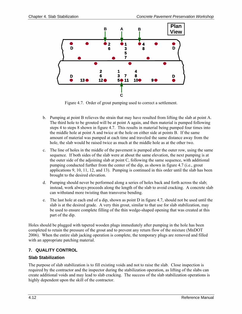
Chapter 4. Slab Stabilization Concrete Pavement Preservation Workshop
4.12 Reference Manual
D48
10D
26
12711
13513 9
D D1357
26
48
D48
10D
26
12711
13513 9
D48
10D
26
12711
13513 99
D D1357
26
48D D
1357
26
48
B A
C
B Plan View
Figure 4.7. Order of grout pumping used to correct a settlement.
b. Pumping at point B relieves the strain that may have resulted from lifting the slab at point A. The third hole to be grouted will be at point A again, and then material is pumped following steps 4 to steps 8 shown in figure 4.7. This results in material being pumped four times into the middle hole at point A and twice at the hole on either side at points B. If the same amount of material was pumped at each time and traveled the same distance away from the hole, the slab would be raised twice as much at the middle hole as at the other two.
c. The line of holes in the middle of the pavement is pumped after the outer row, using the same sequence. If both sides of the slab were at about the same elevation, the next pumping is at the outer side of the adjoining slab at point C, following the same sequence, with additional pumping conducted further from the center of the dip, as shown in figure 4.7 (i.e., grout applications 9, 10, 11, 12, and 13). Pumping is continued in this order until the slab has been brought to the desired elevation.
d. Pumping should never be performed along a series of holes back and forth across the slab; instead, work always proceeds along the length of the slab to avoid cracking. A concrete slab can withstand more twisting than transverse bending.
e. The last hole at each end of a dip, shown as point D in figure 4.7, should not be used until the slab is at the desired grade. A very thin grout, similar to that use for slab stabilization, may be used to ensure complete filling of the thin wedge-shaped opening that was created at this part of the dip.
Holes should be plugged with tapered wooden plugs immediately after pumping in the hole has been completed to retain the pressure of the grout and to prevent any return flow of the mixture (MnDOT 2006). When the entire slab jacking operation is complete, the temporary plugs are removed and filled with an appropriate patching material. 7. QUALITY CONTROL Slab Stabilization The purpose of slab stabilization is to fill existing voids and not to raise the slab. Close inspection is required by the contractor and the inspector during the stabilization operation, as lifting of the slabs can create additional voids and may lead to slab cracking. The success of the slab stabilization operations is highly dependent upon the skill of the contractor.
Concrete Pavement Preservation Workshop Chapter 4. Slab Stabilization
Reference Manual 4.13
The grout injection should start with a low pumping rate and pressure and should be pumped until one of the following conditions occurs (Darter, Barenberg, and Yrjanson 1985):
The maximum allowable pressure of 0.69 MPa (100 lbf/in2) at the grout plant is obtained. Note that a short surge up to 1.38 MPa (200 lbf/in2) can be allowed when starting to pump in order for the grout to penetrate the void structure, if necessary.
The slab lift exceeds 3 mm (0.125 in).
Grout is observed flowing from adjacent holes, cracks, or joints.
Grout is being pumped unnecessarily under the shoulder, as indicated by lifting.
More than about 1 minute has elapsed (any longer than this indicates the grout is flowing into a cavity).
The uplift for any given slab corner should be monitored using a modified Benkelman Beam or other similar device that is capable of detecting 0.025 mm (0.001 in) of uplift movement. The effectiveness of slab stabilization can be determined only by monitoring the subsequent performance of the pavement. The best early indication of effectiveness is obtained by measuring slab deflections before and after grouting to determine if the magnitude of the deflection has been significantly reduced by the process. Figure 4.8 shows measured corner deflections (before and after grouting) for an example joint. If the retesting still indicates a loss of support, the slabs should be regrouted using new drilled holes. ACPA guidelines recommend that if voids are still present after three attempts to stabilize the slab, other methods of repair should be considered (e.g., full-depth repair) (ACPA 2003).
20
Corner Deflection (milli-inches)
FWD
load
(ki
ps)
1 in = 25.4 mm
10
Joint 15
LEAVE (Before Grout)
LEAVE (Afte
r Grou
t)
APPROACH
15
10
5
020 30 40 50
20
Corner Deflection (milli-inches)
FWD
load
(ki
ps)
1 in = 25.4 mm
10
Joint 15
LEAVE (Before Grout)
LEAVE (Afte
r Grou
t)
APPROACH
15
10
5
020 30 40 50
Figure 4.8. Example of load versus deflection plot before and after slab stabilization
(Darter, Barenberg, and Yrjanson 1985).
Slab Jacking The primary concern on slab jacking is excessively raising the slab, which can induce stress concentrations in the slab and produce cracking. Therefore, it is critical that the slab be raised no more than 6 mm (0.25 in) when pumping at each hole. Moreover, during the lifting process, no portion of the slab should be more than 6 mm (0.25 in) higher than any other part of the slab (or an adjacent slab) at any time. The entire working slab and all those adjacent to it must be kept in the same plane, within 6 mm (0.25 in), throughout the entire operation to avoid cracking.
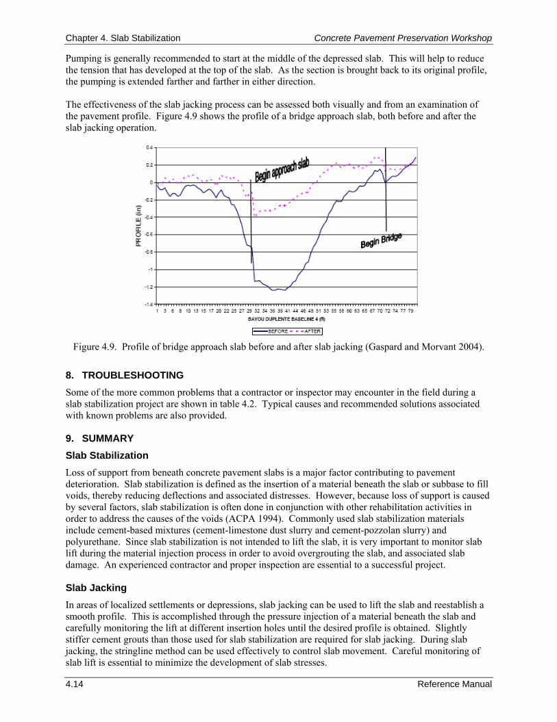
Chapter 4. Slab Stabilization Concrete Pavement Preservation Workshop
4.14 Reference Manual
Pumping is generally recommended to start at the middle of the depressed slab. This will help to reduce the tension that has developed at the top of the slab. As the section is brought back to its original profile, the pumping is extended farther and farther in either direction. The effectiveness of the slab jacking process can be assessed both visually and from an examination of the pavement profile. Figure 4.9 shows the profile of a bridge approach slab, both before and after the slab jacking operation.
Figure 4.9. Profile of bridge approach slab before and after slab jacking (Gaspard and Morvant 2004).
8. TROUBLESHOOTING Some of the more common problems that a contractor or inspector may encounter in the field during a slab stabilization project are shown in table 4.2. Typical causes and recommended solutions associated with known problems are also provided. 9. SUMMARY Slab Stabilization Loss of support from beneath concrete pavement slabs is a major factor contributing to pavement deterioration. Slab stabilization is defined as the insertion of a material beneath the slab or subbase to fill voids, thereby reducing deflections and associated distresses. However, because loss of support is caused by several factors, slab stabilization is often done in conjunction with other rehabilitation activities in order to address the causes of the voids (ACPA 1994). Commonly used slab stabilization materials include cement-based mixtures (cement-limestone dust slurry and cement-pozzolan slurry) and polyurethane. Since slab stabilization is not intended to lift the slab, it is very important to monitor slab lift during the material injection process in order to avoid overgrouting the slab, and associated slab damage. An experienced contractor and proper inspection are essential to a successful project. Slab Jacking In areas of localized settlements or depressions, slab jacking can be used to lift the slab and reestablish a smooth profile. This is accomplished through the pressure injection of a material beneath the slab and carefully monitoring the lift at different insertion holes until the desired profile is obtained. Slightly stiffer cement grouts than those used for slab stabilization are required for slab jacking. During slab jacking, the stringline method can be used effectively to control slab movement. Careful monitoring of slab lift is essential to minimize the development of slab stresses.
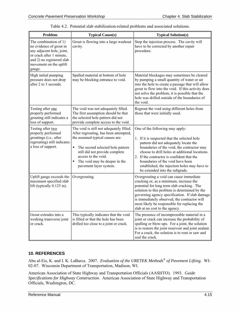
Concrete Pavement Preservation Workshop Chapter 4. Slab Stabilization
Reference Manual 4.15
Table 4.2. Potential slab stabilization-related problems and associated solutions.
Problem Typical Cause(s) Typical Solution(s)
The combination of 1) no evidence of grout in any adjacent hole, joint, or crack after 1 minute, and 2) no registered slab movement on the uplift gauge.
Grout is flowing into a large washout cavity.
Stop the injection process. The cavity will have to be corrected by another repair procedure.
High initial pumping pressure does not drop after 2 to 3 seconds.
Spalled material at bottom of hole may be blocking entrance to void.
Material blockages may sometimes be cleared by pumping a small quantity of water or air into the hole to create a passage that will allow grout to flow into the void. If this activity does not solve the problem, it is possible that the hole was drilled outside of the boundaries of the void.
Testing after one properly performed grouting still indicates a loss of support.
The void was not adequately filled. The first assumption should be that the selected hole pattern did not provide complete access to the void.
Regrout the void using different holes from those that were initially used.
Testing after two properly performed groutings (i.e., after regrouting) still indicates a loss of support.
The void is still not adequately filled. After regrouting, has been attempted, the assumed typical causes are: The second selected hole pattern
still did not provide complete access to the void.
The void may be deeper in the pavement layer system.
One of the following may apply: 1. If it is suspected that the selected hole
pattern did not adequately locate the boundaries of the void, the contractor may choose to drill holes at additional locations.
2. If the contractor is confident that the boundaries of the void have been established, the injection holes may have to be extended into the subgrade.
Uplift gauge exceeds the maximum specified slab lift (typically 0.125 in).
Overgrouting.
Overgrouting a void can cause immediate cracking or, as a minimum, increase the potential for long term slab cracking. The solution to this problem is determined by the governing agency specification. If slab damage is immediately observed, the contractor will most likely be responsible for replacing the slab at no cost to the agency.
Grout extrudes into a working transverse joint or crack.
This typically indicates that the void is filled or that the hole has been drilled too close to a joint or crack.
The presence of incompressible material in a joint or crack can increase the probability of spalling or blow-ups. For a joint, the solution is to restore the joint reservoir and joint sealant. For a crack, the solution is to rout or saw and seal the crack.
10. REFERENCES Abu al-Eis, K. and I. K. LaBarca. 2007. Evaluation of the URETEK Methods® of Pavement Lifting. WI-02-07. Wisconsin Department of Transportation, Madison, WI.
American Association of State Highway and Transportation Officials (AASHTO). 1993. Guide Specifications for Highway Construction. American Association of State Highway and Transportation Officials, Washington, DC.
Chapter 4. Slab Stabilization Concrete Pavement Preservation Workshop
4.16 Reference Manual
American Coal Ash Association (ACAA). 2003. Fly Ash Facts for Engineers. FHWA-IF-039-019. Federal Highway Administration, Washington, DC.
American Concrete Pavement Association (ACPA). 1994. Slab Stabilization Guidelines for Concrete Pavements. TB018P. American Concrete Pavement Association, Skokie, IL.
American Concrete Pavement Association (ACPA). 2003. Concrete Pavement Repair Manual. Report No. JP002P. American Concrete Pavement Association, Skokie, IL.
Barron, B. 2004. “50-50 Change: Kansas DOT Decides to Go With Uretek to Correct 50 Miles of Highway 50.” Roads and Bridges, Vol. 42, No. 12. Scranton-Gillette Communications, Inc., Arlington Heights, IL.
Barnett, T. L., M. I. Darter, and N. R. Laybourne. 1980. Evaluation of Maintenance/Rehabilitation Alternatives for CRCP. Research Report No. 901-3. Illinois Department of Transportation, Springfield, IL.
Chapin, L. T. and T. D. White. 1993. “Validating Loss of Support for Concrete Pavements.” Proceedings, Fifth International Conference on Concrete Pavement and Rehabilitation. Purdue University, West Lafayette, IN.
Crovetti, J. A. and M. I. Darter. 1985. “Void Detection For Jointed Concrete Pavements.” Transportation Research Record 1041. Transportation Research Board, Washington, DC.
Darter, M. I., E. J. Barenberg, and W. A. Yrjanson. 1985. Joint Repair Methods for Portland Cement Concrete Pavements. NCHRP Report 281. Transportation Research Board, Washington, DC.
Donahue, J., S. Johnson, and E. Burks. 2000. Evaluation of Undersealing and Diamond Grinding Rehabilitation. RDT Report RI86-002 and RI96-017. Missouri Department of Transportation, Jefferson City, MO.
Gaspard, K. and M. Morvant. 2004. Assessment of the Uretek Process on Continuously Reinforced Concrete Pavement, Jointed Concrete Pavement, and Bridge Approach Slabs. Technical Assistance Report Number 03-2TA. Louisiana Transportation Research Center, Baton Rouge, LA.
Hoerner, T. E., K. D. Smith, H. T. Yu, D. G. Peshkin, and M. J. Wade. 2001. PCC Pavement Evaluation and Rehabilitation. Reference Manual, NHI Course 131062. National Highway Institute, Arlington, VA.
Maser, K. R. 2000. “Pavement Characterization Using Ground Penetrating Radar: State of the Art and Current Practice.” Nondestructive Testing of Pavements and Backcalculation of Moduli: Third Volume. Special Technical Publication (STP) 1375. American Society for Testing and Materials, West Conshohocken, PA.
Minnesota Department of Transportation (MnDOT). 2006. State Aid Concrete Pavement Rehabilitation Best Practices Manual 2006. Manual Number 2006-31. Minnesota Department of Transportation, St. Paul, MN.
Morey, R. M. 1998. Ground Penetrating Radar for Evaluating Subsurface Conditions for Transportation Facilities. NCHRP Report 255. Transportation Research Board, Washington, DC.
Soltesz, S. 2000. Injected Polyurethane Slab Jacking. Interim Report, Report No. SPR 306-261. Oregon Department of Transportation, Research Group, Salem, OR.
Taha, R., A. Selim, S. Hasan, and B. Lunde. 1994. “Evaluation of Highway Undersealing Practices of Portland Cement Concrete Pavements.” Transportation Research Record 1449. Transportation Research Board, Washington, DC.
URETEK. 2007. The URETEK Method™ for Roadways and Transportation Assets. Technical White Paper. URETEK USA, Tomball, TX. (www.uretekusa.com).
Wu, S. S. 1991. “Concrete Slabs Stabilized by Subsealing: A Performance Report.” Transportation Research Record 1307. Transportation Research Board, Washington, DC.
Concrete Pavement Preservation Workshop Chapter 5. Partial-Depth Repairs
Reference Manual 5.1
CHAPTER 5. PARTIAL-DEPTH REPAIRS 1. LEARNING OUTCOMES This chapter describes recommended procedures for the partial-depth repair of concrete pavements. Upon completion of this chapter, the participants should be able to accomplish the following:
1. List benefits and appropriateness of using partial-depth repairs.
2. List the advantages and disadvantages of different repair materials.
3. Describe recommended construction procedures.
4. Identify typical construction problems and appropriate remedies. 2. INTRODUCTION Partial-depth repairs are defined as the removal of small, shallow areas of deteriorated concrete that are then replaced with a suitable repair material. These repairs restore structural integrity and improve ride quality, thereby extending the service life of pavements that have spalled or distressed joints. Partial-depth repairs of spalled joint areas also restore a well-defined uniform joint sealant reservoir prior to joint resealing. Partial-depth repairs are an alternative to full-depth repairs in areas where slab deterioration is located primarily in the upper one-third of the slab, and the existing load transfer devices (if any) are still functional. When applied at appropriate locations, partial-depth repairs can be more cost-effective than full-depth repairs. The costs of a partial-depth repair are largely dependent upon the size, number, and location of the repair areas, as well as the materials used. Lane closure time and traffic volume also affect production rates and costs. Several resources are available on partial-depth repairs, including ACPA’s Concrete Pavement Field Reference: Preservation and Repair manual (ACPA 2006), the reference manual for the NHI training course PCC Pavement Evaluation and Rehabilitation (Hoerner et al. 2001), and the SHRP manual on concrete pavement rehabilitation (Yu et al. 1994). 3. PURPOSE AND PROJECT SELECTION Partial-depth repairs replace deteriorated concrete only, and most repair materials can not accommodate the movements across working joints and cracks, load transfer devices, or reinforcing steel without experiencing high stresses and material damage. As a result, they are appropriate only for certain types of concrete pavement distresses that are confined to the top one-third of the slab. Distresses that have been successfully corrected with partial-depth repairs include:
Spalling caused by the intrusion of incompressible materials into the joints.
Spalling caused by poor consolidation or inadequate curing.
Spalling caused by localized areas of scaling, weak concrete, clay balls, or high steel.
Surface scaling or deterioration that is limited to the upper one-third of the slab and caused by reinforcing steel that is too close to the surface or by an inadequate air void system.
Spalling caused by the use of joint inserts.
Chapter 5. Partial-Depth Repairs Concrete Pavement Preservation Workshop
5.2 Reference Manual
Concrete pavement distresses that are not candidates for partial-depth repairs include:
Spalling caused by dowel bar misalignment or lockup.
Spalling of transverse or longitudinal cracks caused by shrinkage, fatigue, or foundation movement.
Spalling caused by D-cracking or reactive aggregate. If several severe spalls are present along a transverse joint, it may be more cost effective to perform a full-depth repair at the joint rather than installing a series of individual partial-depth spall repairs (ACPA 2006). 4. LIMITATIONS AND EFFECTIVENESS The performance of partial-depth repairs has been excellent on many projects. Over the years, several studies have demonstrated that properly designed and constructed partial-depth repairs can provide satisfactory performance (McGhee 1981; Snyder et al. 1989; Good-Mojab, Patel, and Romine 1993). However, many partial-depth repair projects have exhibited premature failures, and these have often been attributed to improper construction and placement techniques and not to material deficiencies (Wyant 1984; Jiang and McDaniel 1993). In general, when sound construction practices and a durable material are used, partial-depth repairs can last 5 to 15 years, or longer; when poor materials or workmanship are encountered, partial-depth repairs may fail in as little as 2 to 3 years (ACPA 2006). 5. DESIGN AND MATERIALS CONSIDERATIONS When designing a project with partial-depth repairs, the design engineer needs to determine and mark repair boundaries within the project, and then select a repair material that is appropriate for the project. The first part of this section describes the steps and techniques used to determine and mark individual repair boundaries. The second part of the section focuses on patch repair materials including specific discussions of different available materials commonly used in partial-depth repairs, what to consider when selecting the material for a given project, the types of bonding agents that can be used, and the costs associated with the different material types. Determining Repair Boundaries The first step in the design process is to conduct a field survey of the project to determine repair boundaries for the partial-depth repairs. The actual extent of deterioration in a concrete pavement is often greater than what is visible at the surface. In early stages of spall formation, weakened planes may exist in the slab with no signs of deterioration visible at the surface. During the survey, the extent of deterioration should be determined by “sounding” the concrete with a solid steel rod, chains, or a ball peen hammer. Areas yielding a sharp metallic ringing sound are judged to be acceptable, while those emitting a dull or hollow thud sound are delaminated or unsound (ACPA 2006). All weak and deteriorated concrete must be located and removed if the repair operation is to be effective. The repair boundaries should extend 75 mm (3 in) beyond the detected delaminated or spalled area to ensure removal of all unsound concrete (ACPA 2006). A minimum repair length of 250 mm (10 in) and a minimum repair width of 100 mm (4 in) are recommended (Wilson, Smith, and Romine 1999b). The repair area should also be kept square or rectangular in shape, and in line with the existing joint pattern to avoid irregular shapes that could cause cracks to develop in the repair material (ACPA 2006). If repair areas are closer than 600 mm (24 in) apart, they should be combined to help reduce costs and eliminate numerous small patches (ACPA 2006). All selected patch boundaries should be clearly marked on the pavement by the survey crew.

Concrete Pavement Preservation Workshop Chapter 5. Partial-Depth Repairs
Reference Manual 5.3
Repair Material Types Repair materials for partial-depth repairs are generally classified into three categories: cementitious, polymeric, and bituminous. The specific material selection depends on available curing time, ambient temperature, cost, and the size and depth of the repairs. Because of the multitude of factors that go into the selection process, it is impossible to specify a single repair material for all applications. When the cost of time delays to motorists and the safety hazards to motorists and maintenance crews are considered, many projects, particularly in high traffic volume areas, require that repairs be opened to traffic within a few hours. To meet these challenges, a wide variety of rapid-setting and high-early-strength proprietary materials has been developed (Patel, Mojab, and Romine 1993; Smoak, Husbands, and McDonald 1997 ACI 2006). The remainder of this section introduces the specific material types included within each of these material categories and presents any mix-related concerns associated with each. Cementitious Materials
Cementitious materials include conventional portland cement-based products, gypsum-based (calcium sulfate) products, magnesium phosphate, and high alumina (calcium aluminate) cements. Portland Cement Concrete
High-quality portland cement concrete (PCC) is generally accepted as the most appropriate material for the repair of existing concrete pavements. Typical mixes combine Type I, II, or III portland cement with coarse aggregate not larger than one-half the minimum repair thickness (a 9.5 mm [0.375 in] maximum size is often used). The material should be a low-slump mixture of air-entrained concrete having a water-cement ratio not exceeding 0.44. Type I (GU) portland cement concrete can be used when the patch material can be protected from traffic for at lest 24 hours (ACPA 2006). For faster setting materials such as Type III (HE) cements, patches can be opened as soon as the material can withstand loads without plastic deformation (ACPA 2006). Type I portland cement, with or without admixtures, is more widely used than most other materials because of its relatively low cost, availability, and ease of use. Rich mixtures (up to eight bags of cement, or 446 kg/m3 [752 lb/yd3]) gain strength rapidly in warm weather, although the rate of strength gain may be too slow to permit quick opening to traffic in cool weather. Insulating layers can be used to retain the heat of hydration and reduce curing time. Several proprietary portland cement-based repair materials are available to achieve high-early strength for critical full-depth repairs. One such material, 4x4™ concrete, was developed in response to a California Department of Transportation requirement of having its full-depth repairs achieve a flexural strength of 2.8 MPa (400 lbf/in2) in 4 hours. The material is easy to place and achieves exceptional early strength, and has been approved for use by a number of highway agencies (BASF 2006). Gypsum-Based Concrete
Gypsum-based (calcium sulfate) repair materials gain strength rapidly and can be used in any temperature above freezing. However, gypsum concrete may not perform well when exposed to moisture and freezing weather (ACPA 1998). Additionally, the presence of free sulfates in the typical gypsum mixture may promote steel corrosion in reinforced pavements (Good-Mojab, Patel, and Romine 1993). Magnesium Phosphate Concrete
Magnesium phosphate concretes set very rapidly and produce a high-early-strength, impermeable material that will bond to clean dry surfaces. However, this type of material is extremely sensitive to water, either on the substrate or in the mix (even very small amounts of excess water can reduce strength). Furthermore, magnesium phosphate concrete is very sensitive to aggregate type (for example, some limestones are not acceptable) (Good-Mojab, Patel, and Romine 1993). In hot weather (i.e., above 32 ºC [90 ºF]), many commonly available mixes experience short setting times (e.g., 10 to 15 minutes).
Chapter 5. Partial-Depth Repairs Concrete Pavement Preservation Workshop
5.4 Reference Manual
High Alumina Concrete
Calcium aluminate cements gain strength rapidly, have good bonding properties (on a dry surface), and very low shrinkage. However, due to a chemical conversion that occurs in calcium aluminate cement, particularly at high temperatures during curing, strength loss over time is likely to occur; consequently, these materials are not recommended for use as a patching material (ACPA 1998). Polymer-Based Concretes
Polymer-based concretes are formed by combining polymer resin (molecules of a single family or several similar families linked into molecular chains), aggregate, and an initiator. Aggregate is added to the resin to make the polymer concrete more thermally compatible with the concrete (which would otherwise lead to debonding), to provide a wearing surface, and for economy. The main advantage of polymers is that they set much quicker than most of the cementitious materials. However, they are expensive and can be quite sensitive under certain field conditions. Polymers used for pavement repairs can be classified into four categories: epoxies, methacrylates, polyester-styrenes, and urethanes. Epoxy Concrete
Epoxy concrete repair materials are impermeable and have excellent adhesive properties. When used, it is important that the epoxy concrete be compatible with the concrete in the pavement. Differences in the coefficients of thermal expansion between the repair material and the concrete can cause repair failures, but the use of larger aggregate increases the volume stability and helps reduce the likelihood of debonding (ACPA 1998). Deep epoxy repairs must frequently be placed in multiple lifts to control heat build-up. Methyl Methacrylate Concrete
Methyl methacrylate (MMA) concretes and high molecular weight methacrylate (HMWM) concretes have long working times, high compressive strengths, and good adhesion. Furthermore, they can be placed over a wide range of temperatures, from 4 to 54 oC (40 to 130 oF) (ACPA 1998). However, many methacrylates are volatile and may pose a health hazard to those exposed to the fumes for prolonged periods (Krauss 1985). Polyester-Styrene Concrete
Polyester-styrene polymers have many of the same properties as methyl methacrylates, except that they have a much slower rate of strength gain, which limits their usefulness as a rapid repair material. Polyester-styrene polymers generally cost less and are used more widely than methyl methacrylates (Krauss 1985). Polyurethane Concrete
Polyurethane repair materials generally consist of a two-part polyurethane resin mixed with aggregate (ACPA 1998). Polyurethanes are generally very quick setting (90 seconds), which makes a very quick repair. Some polyurethanes claim to be moisture-tolerant; that is, they can be placed on a wet substrate with no adverse effects. These types of materials have been used for several years with variable results (Krauss 1985). Other Polymeric Materials
There are a number of other polymeric materials available for partial-depth repairs, most of which exhibit rapid strength gain and a high degree of impermeability. Furthermore, some of these materials exhibit certain elastic properties that allow them to be placed across a joint without the need for an insert to maintain the joint.
Concrete Pavement Preservation Workshop Chapter 5. Partial-Depth Repairs
Reference Manual 5.5
Bituminous Materials
Bituminous materials are often used as temporary repair materials on concrete pavements. They have the advantage of being relatively low in cost, widely available, easy to place with small crews, easy to handle, and can be opened to traffic almost immediately. However, because the joint cannot be re-established when using bituminous mixtures, and proper repair techniques are not typically utilized, they are not recommended for permanent repairs. Bituminous patches are often used prior to overlaying, particularly when the existing concrete pavement is too D-cracked or otherwise deteriorated to permit full-depth repairs. Results from the Federal Highway Administration’s (FHWA) long-term monitoring of partial-depth repairs showed that bituminous repair materials performed well for a period of 3 to 4 years, but generally experienced rapid failure after a point where the bituminous material had oxidized and become more brittle (Wilson, Smith, and Romine 1999a). Repair Material Selection Considerations Selection of the proper material should include an evaluation of the material properties. Currently, the most widely reported property used for selection is the strength of the material at a given time (i.e., when the patch can be opened to traffic). However, other factors also play a role in the short- and long-term performance of the patch. Two of the more critical factors are the shrinkage characteristics and coefficient of thermal expansion of the material. Drying shrinkage of most repair materials is greater than normal concrete, and when the material is restrained can induce a tensile stress as high as 6,900 kPa (1,000 lbf/in2) (Emmons, Vaysburd, and McDonald 1993). Differential expansion between the repair material and the surrounding concrete can also be detrimental. Another important property of the repair material is freeze-thaw durability. A study of the properties of repair materials found that the freeze-thaw durability of many materials is unacceptable, especially under severe exposure conditions (Smoak, Husbands, and McDonald 1997). Materials with rapid strength gain characteristics may be particularly susceptible to durability problems because of the accelerated nature of the material and the reduced curing times. The composition of modern cements is such that they gain higher strengths earlier, but have a lower long-term strength gain; this may affect the long-term durability of the concrete (Van Dam et al. 2005). And, depending on the application, early opening times may be desired, which can significantly reduce the available curing time. The early strength criterion and enhanced durability may be most effectively achieved by using high-quality materials, by reducing the w/c, and by increasing the aggregate volume as long as workability is maintained (Van Dam et al. 2005). The FHWA/SHRP Manual of Practice, Materials and Procedures for Rapid Repair of Partial-Depth Spalls in Concrete Pavements, states that premature partial-depth patch failures can be attributed to a number of material-related causes, including (Wilson, Smith, and Romine 1999b):
Incompatibilities between the climatic conditions during repair replacement and the materials or procedures used.
Thermal incompatibility between the repair material and the pavement.
Extreme climatic conditions during the life of the repairs that are beyond the capabilities of the repair material.
Inadequate cure time prior to opening repairs to traffic.
Incompatibility between the joint bond breaker and the joint sealant material. Many highway agencies maintain a qualified products list that can be consulted to help identify appropriate partial-depth repair materials.
Chapter 5. Partial-Depth Repairs Concrete Pavement Preservation Workshop
5.6 Reference Manual
Bonding Agents PCC materials generally require the placement of a bonding agent to enhance the bond between the repair material and the existing pavement. Sand-cement grouts have proven adequate when used as bonding agents with concrete repair materials, provided the repairs are protected from traffic for 24 to 72 hours. Excellent results have been obtained with 7-sack Type III mixes using a sand-cement grout bonding agent, with a cure period of 72 hours before opening to traffic. The recommended mixture for the sand-cement grout consists of one part sand and one part cement by volume, with sufficient water to produce a mortar with a thick, creamy consistency. Epoxy bonding agents have been used successfully with both PCC and proprietary repair materials to reduce the repair closure time to 6 hours or less. Not all repair materials require a bonding agent to promote adhesion, however. Proprietary mixes will specify what type of bonding agent, if any, should be used. Material Cost Considerations Material costs, mechanical properties, workability, and performance vary greatly between the different repair materials. Generally, the more rapid setting the material, the more expensive the product. Other material selection factors to consider include durability and reliability; in many cases, the conventional materials, while they do not gain strength as rapidly, are much more reliable. 6. CONSTRUCTION CONSIDERATIONS The construction and installation of partial-depth repairs involves the following steps:
1. Repair dimension selection.
2. Concrete removal.
3. Repair area preparation.
4. Joint preparation.
5. Bonding agent application.
6. Patch material placement.
7. Curing.
8. Diamond grinding (optional).
9. Joint resealing. A simplified overview of this repair process is illustrated in figure 5.1, with a detailed description of these steps provided in the following sections. A number of manuals that describe the construction procedures for partial-depth repairs are available (Patel, Mojab, and Romine 1993; Wilson, Smith, and Romine 1999b; ACPA 1998; ACPA 2004; ACPA 2006). Step 1: Repair Dimension Selection The first step in the repair process is to determine the boundaries for the partial-depth repairs. As previously described, this is often accomplished by “sounding” the concrete with a solid steel rod, a heavy chain, or a ball peen hammer to determine unsound areas. The repair boundaries should then be clearly marked, keeping in mind the minimum repair dimension requirements of 250 mm (10 in) long and 100 mm (4 in ) wide. Repair boundaries should also be at least 75 mm (3 in) away from the unsound areas. If there is a significant amount of time between the condition survey and the construction process, the repair boundaries should be verified by the construction crew to ensure that the extent of the unsound material has not expanded.
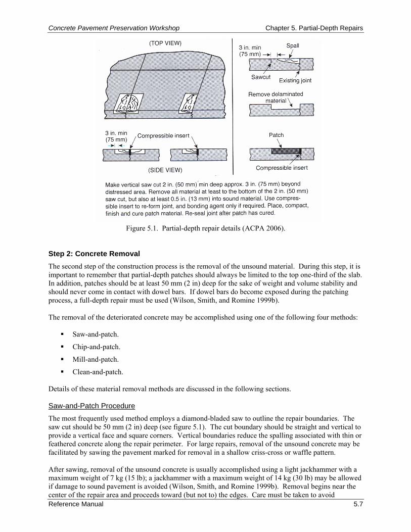
Concrete Pavement Preservation Workshop Chapter 5. Partial-Depth Repairs
Reference Manual 5.7
Figure 5.1. Partial-depth repair details (ACPA 2006). Step 2: Concrete Removal The second step of the construction process is the removal of the unsound material. During this step, it is important to remember that partial-depth patches should always be limited to the top one-third of the slab. In addition, patches should be at least 50 mm (2 in) deep for the sake of weight and volume stability and should never come in contact with dowel bars. If dowel bars do become exposed during the patching process, a full-depth repair must be used (Wilson, Smith, and Romine 1999b). The removal of the deteriorated concrete may be accomplished using one of the following four methods:
Saw-and-patch.
Chip-and-patch.
Mill-and-patch.
Clean-and-patch. Details of these material removal methods are discussed in the following sections. Saw-and-Patch Procedure
The most frequently used method employs a diamond-bladed saw to outline the repair boundaries. The saw cut should be 50 mm (2 in) deep (see figure 5.1). The cut boundary should be straight and vertical to provide a vertical face and square corners. Vertical boundaries reduce the spalling associated with thin or feathered concrete along the repair perimeter. For large repairs, removal of the unsound concrete may be facilitated by sawing the pavement marked for removal in a shallow criss-cross or waffle pattern. After sawing, removal of the unsound concrete is usually accomplished using a light jackhammer with a maximum weight of 7 kg (15 lb); a jackhammer with a maximum weight of 14 kg (30 lb) may be allowed if damage to sound pavement is avoided (Wilson, Smith, and Romine 1999b). Removal begins near the center of the repair area and proceeds toward (but not to) the edges. Care must be taken to avoid
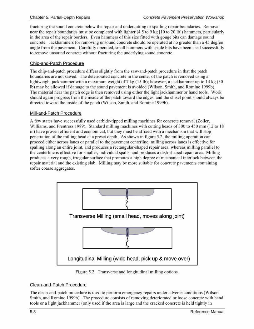
Chapter 5. Partial-Depth Repairs Concrete Pavement Preservation Workshop
5.8 Reference Manual
Transverse Milling (small head, moves along joint)
Longitudinal Milling (wide head, pick up & move over)
Transverse Milling (small head, moves along joint)
Longitudinal Milling (wide head, pick up & move over)
fracturing the sound concrete below the repair and undercutting or spalling repair boundaries. Removal near the repair boundaries must be completed with lighter (4.5 to 9 kg [10 to 20 lb]) hammers, particularly in the area of the repair borders. Even hammers of this size fitted with gouge bits can damage sound concrete. Jackhammers for removing unsound concrete should be operated at no greater than a 45 degree angle from the pavement. Carefully operated, small hammers with spade bits have been used successfully to remove unsound concrete without fracturing the underlying sound concrete. Chip-and-Patch Procedure
The chip-and-patch procedure differs slightly from the saw-and-patch procedure in that the patch boundaries are not sawed. The deteriorated concrete in the center of the patch is removed using a lightweight jackhammer with a maximum weight of 7 kg (15 lb); however, a jackhammer up to 14 kg (30 lb) may be allowed if damage to the sound pavement is avoided (Wilson, Smith, and Romine 1999b). The material near the patch edge is then removed using either the light jackhammer or hand tools. Work should again progress from the inside of the patch toward the edges, and the chisel point should always be directed toward the inside of the patch (Wilson, Smith, and Romine 1999b). Mill-and-Patch Procedure
A few states have successfully used carbide-tipped milling machines for concrete removal (Zoller, Williams, and Frentress 1989). Standard milling machines with cutting heads of 300 to 450 mm (12 to 18 in) have proven efficient and economical, but they must be affixed with a mechanism that will stop penetration of the milling head at a preset depth. As shown in figure 5.2, the milling operation can proceed either across lanes or parallel to the pavement centerline; milling across lanes is effective for spalling along an entire joint, and produces a rectangular-shaped repair area, whereas milling parallel to the centerline is effective for smaller, individual spalls, and produces a dish-shaped repair area. Milling produces a very rough, irregular surface that promotes a high degree of mechanical interlock between the repair material and the existing slab. Milling may be more suitable for concrete pavements containing softer coarse aggregates.
Figure 5.2. Transverse and longitudinal milling options.
Clean-and-Patch Procedure
The clean-and-patch procedure is used to perform emergency repairs under adverse conditions (Wilson, Smith, and Romine 1999b). The procedure consists of removing deteriorated or loose concrete with hand tools or a light jackhammer (only used if the area is large and the cracked concrete is held tightly in
Concrete Pavement Preservation Workshop Chapter 5. Partial-Depth Repairs
Reference Manual 5.9
place). The loosened material is then swept away with stiff brooms. Such a procedure should only be used if a spall is hazardous to highway users and the climate is so adverse that no other procedure can be used (Wilson, Smith, and Romine 1999b). Step 3: Repair Area Preparation Following removal of the concrete, the surface of the repair area must be prepared to provide a clean, irregular surface for the development of a good bond between the repair material and the existing slab. Dry sweeping, sandblasting, and compressed airblasting are normally sufficient for obtaining an adequately clean surface. Sandblasting is a highly recommended step as it is very effective at removing dirt, oil, thin layers of unsound concrete, and laitance. High-pressure water may also be used to remove contaminants, but sandblasting usually produces better results. The compressed air used in the final cleaning must be free of oil, since contamination of the surface will prevent bonding. This can be checked by placing a cloth over the air compressor nozzle and visually inspecting for oil. With any cleaning method, the prepared surface must be checked prior to placing the new material. Any contamination of the surface will reduce the bond between the new material and the existing concrete. If a finger rubbed along the prepared surface picks up any loose material (e.g., dust, asphalt, slurry), the surface should be cleaned again. If there is a delay between cleaning and repair placement, the surface may also have to be cleaned again. Step 4: Joint Preparation The most frequent cause of failure of partial-depth repairs at joints is excessive compressive stresses on the repair material. Partial-depth repairs placed directly against transverse joints and cracks will be crushed by the compressive forces created when the slabs expand and insufficient room is provided for the thermal expansion. Failure may also occur when the repair material is allowed to infiltrate the joint or crack opening below the bottom of the repair, resisting slab movement and thereby preventing the joint or crack from functioning. These damaging stresses may also develop along longitudinal joints or at lane-shoulder joints. Placing a strip of polystyrene, polyethylene, asphalt-impregnated fiberboard, or other compressible material between the new concrete and the adjoining slab (see figure 5.3) will reduce the risk of such failures. Such an insert is typically referred to as a bond breaker (or joint reformer). This insert must be placed so that it prevents intrusion of the repair material into the joint opening. Failure to do so can result in the development of compressive stresses at lower depths that will damage the repair. The insert will also guard against damage due to deflection of the joint under traffic. It is recommended that the compressible insert extend 25 mm (1 in) below and 76 mm (3 in) beyond the repair boundaries. Prior to its placement, the insert is typically scored at an appropriate depth prior to placement. Once the scored bond breaker has been placed in the clean joint, and the patch has been installed and has cured or set, the top strip (above the scoring line) is removed. The removal of the top strip provides a clean surface and a preformed joint reservoir that is ready for the installation of the joint sealant (Wilson, Smith, and Romine 1999b). Some partial-depth repairs have been successfully constructed on both sides of a joint without transverse joint forms by sawing the transverse joint to full depth as soon as the repair material has gained sufficient strength to permit sawing. Timing is absolutely critical in this operation, because any closing of the joint before sawing will fracture the repair. To avoid cracking, joints must be formed with compression-absorbing materials in partial-depth repairs placed across joints and cracks.
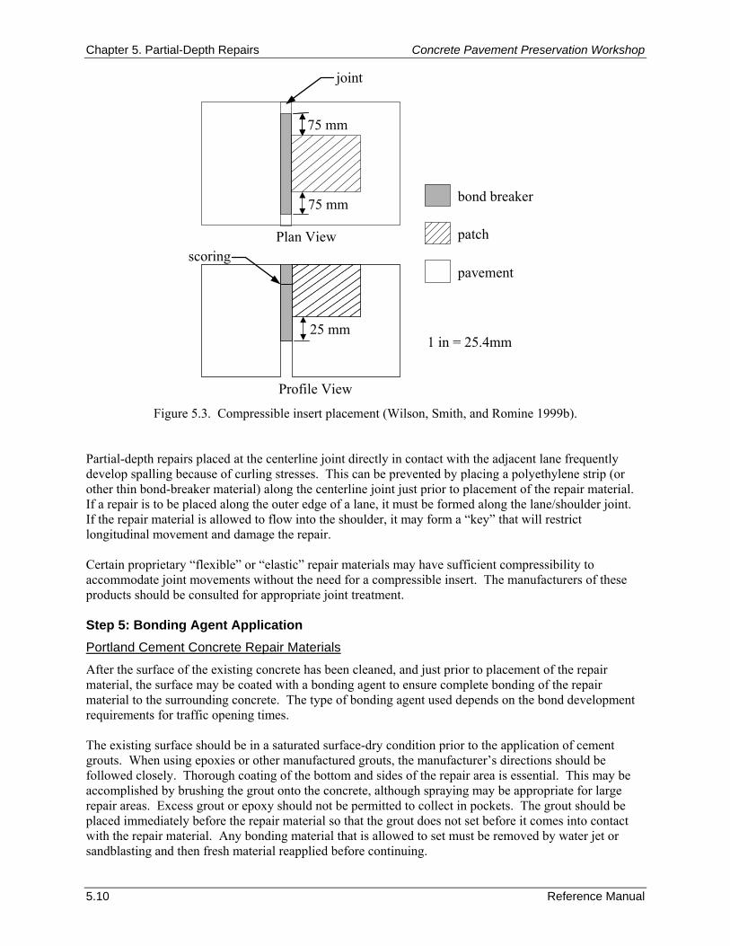
Chapter 5. Partial-Depth Repairs Concrete Pavement Preservation Workshop
5.10 Reference Manual
Plan View
Profile View
bond breaker
patch
pavement
75 mm
75 mm
scoring
25 mm1 in = 25.4mm
joint
Figure 5.3. Compressible insert placement (Wilson, Smith, and Romine 1999b).
Partial-depth repairs placed at the centerline joint directly in contact with the adjacent lane frequently develop spalling because of curling stresses. This can be prevented by placing a polyethylene strip (or other thin bond-breaker material) along the centerline joint just prior to placement of the repair material. If a repair is to be placed along the outer edge of a lane, it must be formed along the lane/shoulder joint. If the repair material is allowed to flow into the shoulder, it may form a “key” that will restrict longitudinal movement and damage the repair. Certain proprietary “flexible” or “elastic” repair materials may have sufficient compressibility to accommodate joint movements without the need for a compressible insert. The manufacturers of these products should be consulted for appropriate joint treatment. Step 5: Bonding Agent Application Portland Cement Concrete Repair Materials
After the surface of the existing concrete has been cleaned, and just prior to placement of the repair material, the surface may be coated with a bonding agent to ensure complete bonding of the repair material to the surrounding concrete. The type of bonding agent used depends on the bond development requirements for traffic opening times. The existing surface should be in a saturated surface-dry condition prior to the application of cement grouts. When using epoxies or other manufactured grouts, the manufacturer’s directions should be followed closely. Thorough coating of the bottom and sides of the repair area is essential. This may be accomplished by brushing the grout onto the concrete, although spraying may be appropriate for large repair areas. Excess grout or epoxy should not be permitted to collect in pockets. The grout should be placed immediately before the repair material so that the grout does not set before it comes into contact with the repair material. Any bonding material that is allowed to set must be removed by water jet or sandblasting and then fresh material reapplied before continuing.
Concrete Pavement Preservation Workshop Chapter 5. Partial-Depth Repairs
Reference Manual 5.11
Rapid-Setting Proprietary Repair Materials
Bonding agents for proprietary repair materials should be those recommended by the manufacturer for the placement conditions. Many proprietary repair materials do not require the use of a bonding agent. Step 6: Patch Material Placement Repair Material Mixing
The volume of material required for a partial-depth repair is usually small (0.014 to 0.056 m3 [0.5 to 2.0 ft3]). Ready-mix trucks and other large equipment cannot efficiently produce such small quantities, since maximum mixing times for a given temperature would be easily exceeded, resulting in waste of material. Small drum or paddle-type mixers with capacities of up to 0.056 m3 (2.0 ft3) are often used. Based on trial batches, repair materials may be weighed and bagged in advance to facilitate the batching process. Continuous feed mixers are also popular. Careful observation of mixing times and water content for prepackaged rapid setting materials is important because of the quick setting nature of the materials. Mixing beyond the amount of time needed for good blending reduces the already short time available for placing and finishing the material. Placement and Consolidation of Material
Portland cement concrete and most of the rapid-setting proprietary repair materials should not be placed when the air temperature or pavement temperature is below 4 ºC (40 ºF). Additional precautions, such as the use of warm water, insulating covers, and longer cure times, may be required at temperatures below 13 ºC (55 ºF). Some polymer concretes and bituminous mixes may be installed under adverse conditions of low temperatures and wet substrates with reasonable success; however, even these materials will perform better when installed under more favorable environmental conditions. Some epoxy concretes may require that the material be placed in lifts not exceeding 50 mm (2 in) due to their high heat of hydration. The time interval between placing additional layers should be such that the temperature of the epoxy concrete does not exceed 60 ºC (140 ºF) at any time during hardening. Almost all repair materials require consolidation during placement. Failure to properly consolidate concrete results in poor repair durability, spalling, and rapid deterioration. Consolidation provides a more dense mixture by releasing trapped air from the fresh mix, thereby contributing to the overall performance of the patch. Three common methods of achieving consolidation follow:
Use of internal vibrators with small heads (less than 25 mm [1 in] in diameter).
Use of vibrating screeds.
Rodding or tamping and cutting with a trowel or other hand tool. The internal vibrator and the vibrating screed give the most consistent results. The internal vibrator is often more readily available and is used most often, although very small repairs may require the use of hand tools. The placement and consolidation procedure begins by slightly over-filling the area with repair material to allow for a reduction in volume during consolidation. The vibrator is held at a slight angle (15 to 30 degrees) from the vertical and is moved through the repair in such a way as to vibrate the entire repair area. The vibrator should not be used to move material from one place to another within the repair as this may result in segregation. Adequate consolidation is achieved when the mix stops settling, air bubbles no longer emerge, and a smooth layer of mortar appears at the surface.
Chapter 5. Partial-Depth Repairs Concrete Pavement Preservation Workshop
5.12 Reference Manual
On very small repairs, the mix can be consolidated using hand tools. Cutting with a trowel seems to give better results than rodding or tamping. The tools used should be small enough to easily work in the area being repaired. Screeding and Finishing
Partial-depth repairs are usually small enough so that a stiff board can be used to screed the repair surface and make it flush with the existing pavement. The materials should be worked toward the perimeter of the repair to establish contact and enhance bonding to the existing slab. At least two passes should be made to ensure a smooth repair surface. Partial-depth repairs typically cover only a small percentage of the pavement surface and have little effect on skid resistance. Nonetheless, the surface of the repair should be textured to match that of the surrounding slab as much as possible. The patch/slab interface should be sealed with a one-to-one cement grout in order to form a moisture barrier over the interface and to impede delamination of the patch (ACPA 2006). Delamination of the patch can also start to occur if water at the interface freezes in cold weather (ACPA 2006). Sawcut runouts extending beyond the patch perimeter at patch corners also can be filled with grout to help prevent moisture penetration that may negatively affect the bond (ACPA 2006). In lieu of grout, the sawcut runouts can be sealed with the material used to seal the adjacent joint or crack. Step 7: Curing Because partial-depth repairs have large surface areas in relation to their volumes, moisture can be lost quickly. Thus, curing is an important component of the construction process and must be effectively conducted in order to prevent the development of shrinkage cracks that may cause the repair to fail prematurely. Curing Methods
For PCC materials, the most common curing method is to apply a white-pigmented curing compound as soon as water has evaporated from the repair surface. This will reflect radiant heat while allowing the heat of hydration to escape, and will provide protection for several days. Some agencies require that curing compound be applied at 1.5 to 2 times the normal application rate to prevent shrinkage cracks in the repairs. Moist burlap and polyethylene may also be used, and in cold weather the use of insulating blankets or tarps may be required to help retain heat. Curing of proprietary repair materials should be conducted in accordance with the manufacturer’s recommendations. Opening to Traffic
It is important that the partial-depth repair attain sufficient strength before it is opened to traffic. Generally, compressive strengths in the range of 13.8 to 21.7 MPa (2,000 to 3,000 lbf/in2) are required by many agencies before the partial-depth repair is opened to traffic. Step 8: Optional Diamond Grinding Rehabilitation techniques such as partial-depth repair may result in increased roughness if not finished properly. This is typically due to differences in elevation between the repair areas and the existing pavement. It is often desirable to blend partial-depth repairs into a concrete pavement with diamond grinding, which leaves a smooth surface that matches the surrounding pavement. Step 9: Joint Resealing The final step in the partial-depth repair procedure is the restoration of joints. This is accomplished by resawing the joint to a new shape factor, sandblasting and airblasting both faces of the joint, inserting a closed cell backer rod, and applying the sealer. More detailed information on joint resealing can be found in Chapter 10 (Joint Resealing).

Concrete Pavement Preservation Workshop Chapter 5. Partial-Depth Repairs
Reference Manual 5.13
7. QUALITY CONTROL The combination of proper design procedures and sufficient construction quality control (QC) is extremely important to achieving well performing partial-depth repairs. On many projects where QC inspections have been known to be less stringent, performance has typically been found to be unsatisfactory. Some of the common causes of failure include inappropriate use, lack of bond, compression failure of the patch (due to failure to re-establish the joint), variability in the effectiveness of repair material, improper use of repair materials, insufficient consolidation, and incompatibility in thermal expansion between the repair material and the original slab. This section summarizes key portions of a recently developed checklist that has been compiled to facilitate the successful design and construction of good performing partial-depth repairs (FHWA 2005). Although these procedures do not necessarily ensure the long-term performance of a specific repair, the checklist topics are intended to remind both the agency and contractor personnel of those specific design and construction topics that have the potential of influencing the performance of the repair. These checklist items are divided into general categories of preliminary responsibilities, equipment inspections, weather requirements, traffic control, and project inspection responsibilities. Preliminary Responsibilities As a first step of the QC process, agency and contractor personnel should collectively conduct a review of the project documentation, project scope and intended construction procedures, and material usage and associates specifications. Such a collective review is intended to minimize any misunderstandings in the field between agency designers, inspectors, and construction personnel. Specific checklist items for this review are summarized below. Document Review
As a first step, review the following project-related documents:
Bid/project specifications and design.
Applicable special provisions.
Agency application requirements.
Traffic control plan.
Manufacturer’s specific installation instructions for chosen patch material(s).
Manufacturer’s material safety data sheets (MSDS). Project Review
In an attempt to maximize the efficiency of the field construction process, review the following project scope-related items:
Verify that pavement conditions have not significantly changed since the project was designed and that a partial-depth repair is still appropriate for the pavement.
Verify that the estimated number of partial-depth repairs agrees with the number specified in the contract.
Agree on quantities to be placed, but allow flexibility if additional deterioration is found below the surface.
Some partial-depth repairs may become full-depth repairs if deterioration extends below the top one-third of the slab. Make sure that the criteria for identifying this change are understood.
Chapter 5. Partial-Depth Repairs Concrete Pavement Preservation Workshop
5.14 Reference Manual
Materials Checks
A number of material-related checks are recommended prior to the start of a partial-depth repair project. Specifically, agency and contractor personnel should collectively verify that:
The selected patch material is of the correct type and meets specifications.
The patch material is obtained from an approved source or is listed on the agency Qualified Products List as required by the contract documents.
The patch material has been sampled and tested prior to installation as required by the contract documents.
Additional or extender aggregates have been properly produced and meet requirements of contract documents.
Material packaging is not damaged so as to prevent proper use (for example, packages are not leaking, torn, or pierced).
Bonding agent (if required) meets specifications.
Curing compound (if required) meets specifications.
Joint/crack re-former material (compressible insert) meets specifications (typically polystyrene foam board, 12 mm [0.5 in] thick).
Joint sealant material meets specification requirements.
Sufficient quantities of materials are on hand for completion of the project. Equipment Inspections
A second step in the QC process involves the inspection of all equipment that will be utilized in the construction of partial-depth repairs. Ensuring that construction equipment is in good working order will help avoid construction-related problems during the construction process. The following items should be checked or verified as part of the equipment inspection process prior to the start of a partial-depth repair project. Concrete Removal Equipment
Verify that concrete saws are of sufficient weight and horsepower to adequately cut the existing concrete pavement to the depth required along the patch boundaries as required by the contract documents.
Verify that the concrete saws and blades are in good working order.
Verify that pavement milling machines are power operated, self-propelled, cold milling machines capable of removing concrete as required by the contract documents.
Verify that milling machines used for concrete removal are equipped with a device that allows them to stop at pre-set depths to prevent removal of more than the top third of the slab and to prevent damage to embedded steel.
Verify that the maximum rated weight of removal jackhammers is 14 kg (30 lbs). Patch Area Cleaning Equipment
Verify that the sandblasting unit is adjusted for correct sand rate and that it is equipped with and using properly functioning oil/moisture traps.
Verify that air compressors have sufficient pressure and volume capabilities to clean patch area adequately in accordance with contract specifications.

Concrete Pavement Preservation Workshop Chapter 5. Partial-Depth Repairs
Reference Manual 5.15
Verify that air compressors are equipped with and using properly functioning oil and moisture filters/traps. This can be accomplished by passing the air stream over a board, and then examining for contaminants.
Verify that the volume and pressure of waterblasting equipment (if used) meets the specifications. Mixing and Testing Equipment
Verify that auger flights and paddles within auger-type mixing equipment are kept free of material buildup that can result in inefficient mixing operations.
Ensure that volumetric mixing equipment such as mobile mixers are kept in good condition and are calibrated on a regular basis to properly proportion mixes.
Verify that the concrete testing technician meets the requirements of the contract documents for training/certification.
Ensure that material test equipment required by the specifications is all available on-site and in proper working condition (equipment typically includes slump cone, pressure-type air meter, cylinder molds and lids, rod, mallet, ruler, and 3-m [10-ft] straightedge).
Placing and Finishing Equipment
Verify that a sufficient number of concrete vibrators (25 mm [1 in] diameter or less) is available on-site and in proper working condition.
Verify that all floats and screeds are straight, free of defects, and capable of producing the desired finish.
Other Equipment
Ensure that a steel chain, rod, or hammer is available to check for unsound concrete around the patch area.
Verify that grout-application brushes (if necessary) are available. Weather Limitations
Immediately prior to the start of the construction project, the following weather-related concerns should be checked:
Review manufacturer installation instructions for requirements specific to the patch material being used.
Ensure that air and surface temperature meets manufacturer and contract requirements (typically 4 °C [40 °F] and above) for concrete placement.
Ensure that patching does not proceed if rain is imminent. Traffic Control
The developed traffic control plan should be reviewed by field personnel prior to construction. Specifically, the following pre- and post-construction traffic-related items should be verified:
Verify that the signs and devices used match the traffic control plan presented in the contract documents.
Verify that the set-up complies with the Federal or local agency Manual on Uniform Traffic Control Devices (MUTCD) or local agency procedures.
Verify that traffic control personnel are trained/qualified according to contract documents and agency requirements.

Chapter 5. Partial-Depth Repairs Concrete Pavement Preservation Workshop
5.16 Reference Manual
Verify that unsafe conditions, if any, are reported to a supervisor.
Ensure that traffic is not opened to the repaired pavement until the patch material meets strength requirements presented in the contract documents.
Verify that signs are removed or covered when they are no longer needed. Project Inspection Responsibilities During the construction process, careful project inspection by construction inspectors can greatly increase the chances of obtaining well performing partial-depth patches. Specifically, the following checklist items (organized by construction activity) summarize the recommended project inspection items. Patch Removal and Cleaning
Ensure that the area surrounding the patch is checked for delamination and unsound concrete using steel chain, rod, or hammer.
Ensure that the boundaries of unsound concrete area(s) are marked at least 75 mm (3 in) beyond the area of deterioration.
Verify that concrete is removed by either (1) sawcutting the boundaries and jackhammering interior concrete; or (2) using a cold milling machine.
Verify that concrete removal extends at least 50 mm (2 in) deep and does not extend below one-third of the slab depth, and that load transfer devices are not exposed.
Verify that, after concrete removal, the patch area is prepared by sandblasting or waterblasting.
Verify that the patch area is cleaned by air blasting. A second air blasting may be required immediately before placement of patch material if patches are left exposed for a period of time longer than that specified in the contract documents.
Patch Preparation
Ensure that the patch is effectively sandblasted (or waterblasted) to remove any dirt, debris, or laitance.
Ensure that compressible joint inserts (joint/crack re-formers) are inserted into existing cracks/joints in accordance with contract documents. Joint inserts are typically required to extend both below and outside patch area by 12 mm (0.5 in).
When a patch abuts a bituminous shoulder, ensure that a wooden form is used to prevent patch material from entering the shoulder joint.
Ensure that the bonding agent (epoxy- or cement-based) is placed on the clean, prepared surface of existing concrete immediately prior to the placement of patch material as required by the contract documents. If the bonding agent shows any sign of drying before the patch material is placed, it must be removed by sandblasting, cleaned with compressed air, and re-applied.
Verify that cement-based bonding agents are applied using wire brush, and epoxy bonding agents are applied using soft brush.
Placing, Finishing, and Curing Patch Material
Verify that quantities of patch material being mixed are relatively small to prevent material from setting prematurely.
Verify that the fresh concrete is properly consolidated using several vertical penetrations of the surface with a hand-held vibrator.

Concrete Pavement Preservation Workshop Chapter 5. Partial-Depth Repairs
Reference Manual 5.17
Verify that the surface of the concrete patch is level with the adjacent slab using a straightedge in accordance with contract documents. The material should be worked from the center of the patch outward toward the boundary to prevent pulling material away from the patch boundaries.
Verify that the surface of the fresh patch material is finished and textured to match the adjacent surface.
Verify that the perimeter of the patch and sawcut runouts (if saws are used) are sealed using grout material. Alternatively, sawcut runouts can be sealed using joint sealant material.
Verify that adequate curing compound is applied to the surface of the finished and textured, fresh patch material in accordance with contract documents.
Ensure that insulation blankets are used when ambient temperatures are expected to fall below 4 °C (40 °F). Maintain blanket cover until concrete attains the strength required in the contract documents.
Resealing Joints and Cracks
Verify that the compressible inserts are sawed out to the dimensions specified in the contract documents when the patch material has attained sufficient strength to support concrete saws.
Verify that joints are cleaned and resealed according to contract documents. Clean Up Responsibilities
Verify that all concrete pieces and loose debris are removed from the pavement surface and disposed of in accordance with contract documents.
Verify that mixing, placement, and finishing equipment is properly cleaned for the next use. 8. TROUBLESHOOTING As mentioned previously, poor performing partial-depth repairs are typically attributed to inappropriate use, improper design, or improper construction and placement techniques. While paying close attention to the checklist items in the previous section attempts to minimize any design or construction-related problems, construction problems do sometimes develop in the field. Some of the more typical problems that are encountered either during or after construction are summarized in table 5.1. Typical causes and recommended solutions accompany each of the identified potential problems. 9. SUMMARY Partial-depth repairs are an excellent tool for restoring rideability and the overall integrity of a concrete pavement. A broad range of products is available for these types of repairs, and the selection of the proper material is dependent upon the specific project requirements. Each material will call for different handling and mixing steps. However, all of the products require the same surface preparation steps. Taking the time to properly prepare the repair area, following the manufacturers’ recommendations when placing the materials, and paying attention to weather concerns during placement and curing, will all contribute to the long-term performance of the partial-depth repair. 10. REFERENCES American Concrete Institute (ACI). 2006. Guide for the Selection of Materials for the Repair of Concrete. ACI 546.3R-06. American Concrete Institute, Farmington Hills, MI.
American Concrete Pavement Association (ACPA). 1998. Guidelines for Partial-Depth Repair. Technical Bulletin TB003.02P. American Concrete Pavement Association, Arlington Heights, IL.
American Concrete Pavement Association (ACPA). 2004. Concrete Crack and Partial-Depth Spall Repair Manual. Report JP003P. American Concrete Pavement Association, Skokie, IL.
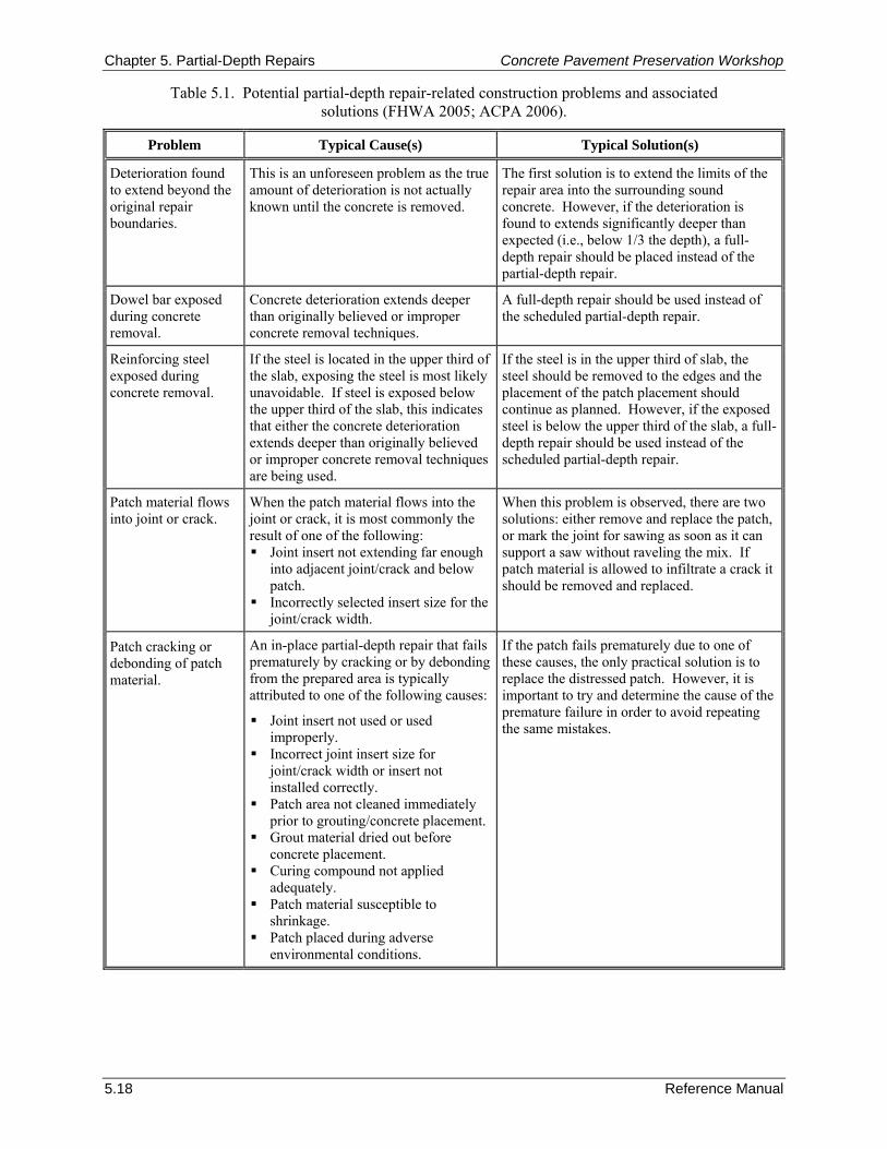
Chapter 5. Partial-Depth Repairs Concrete Pavement Preservation Workshop
5.18 Reference Manual
Table 5.1. Potential partial-depth repair-related construction problems and associated solutions (FHWA 2005; ACPA 2006).
Problem Typical Cause(s) Typical Solution(s)
Deterioration found to extend beyond the original repair boundaries.
This is an unforeseen problem as the true amount of deterioration is not actually known until the concrete is removed.
The first solution is to extend the limits of the repair area into the surrounding sound concrete. However, if the deterioration is found to extends significantly deeper than expected (i.e., below 1/3 the depth), a full-depth repair should be placed instead of the partial-depth repair.
Dowel bar exposed during concrete removal.
Concrete deterioration extends deeper than originally believed or improper concrete removal techniques.
A full-depth repair should be used instead of the scheduled partial-depth repair.
Reinforcing steel exposed during concrete removal.
If the steel is located in the upper third of the slab, exposing the steel is most likely unavoidable. If steel is exposed below the upper third of the slab, this indicates that either the concrete deterioration extends deeper than originally believed or improper concrete removal techniques are being used.
If the steel is in the upper third of slab, the steel should be removed to the edges and the placement of the patch placement should continue as planned. However, if the exposed steel is below the upper third of the slab, a full-depth repair should be used instead of the scheduled partial-depth repair.
Patch material flows into joint or crack.
When the patch material flows into the joint or crack, it is most commonly the result of one of the following: Joint insert not extending far enough
into adjacent joint/crack and below patch.
Incorrectly selected insert size for the joint/crack width.
When this problem is observed, there are two solutions: either remove and replace the patch, or mark the joint for sawing as soon as it can support a saw without raveling the mix. If patch material is allowed to infiltrate a crack it should be removed and replaced.
Patch cracking or debonding of patch material.
An in-place partial-depth repair that fails prematurely by cracking or by debonding from the prepared area is typically attributed to one of the following causes:
Joint insert not used or used improperly.
Incorrect joint insert size for joint/crack width or insert not installed correctly.
Patch area not cleaned immediately prior to grouting/concrete placement.
Grout material dried out before concrete placement.
Curing compound not applied adequately.
Patch material susceptible to shrinkage.
Patch placed during adverse environmental conditions.
If the patch fails prematurely due to one of these causes, the only practical solution is to replace the distressed patch. However, it is important to try and determine the cause of the premature failure in order to avoid repeating the same mistakes.
Concrete Pavement Preservation Workshop Chapter 5. Partial-Depth Repairs
Reference Manual 5.19
American Concrete Pavement Association (ACPA). 2006. Concrete Pavement Field Reference - Preservation and Repair. Report EB239P. American Concrete Pavement Association, Skokie, IL.
BASF Admixtures, Inc. (BASF). 2006. Products in Practice: 4x4™ Concrete, Very High-Early Strength Concrete Mixture. BASF Admixtures, Inc., Cleveland, OH.
Emmons, P. H., A. M. Vaysburd, and J. E. McDonald. 1993. “A Rational Approach to Durable Concrete Repairs.” Concrete International. American Concrete Institute, Farmington Hills, MI.
Federal Highway Administration (FHWA). 2005. Pavement Preservation Checklist Series #9: Partial-Depth Repair of Portland Cement Concrete Pavements. FHWA-IF-03-042. Federal Highway Administration, Washington, DC.
Good-Mojab, C. A., A. J. Patel, and A. R. Romine. 1993. Innovative Materials Development and Testing. Volume 5—Partial Depth Spall Repair. SHRP-H-356. Strategic Highway Research Program, Washington, DC.
Hoerner, T. E., K. D. Smith, H. T. Yu, D. G. Peshkin, and M. J. Wade. 2001. PCC Pavement Evaluation and Rehabilitation. Reference Manual for NHI Course No. 131062. National Highway Institute, Arlington, VA.
Jiang, Y., and R. R. McDaniel. 1993. “Evaluation of the Impact of Concrete Pavement Restoration Techniques on Pavement Performance.” Proceedings of the Fifth International Conference on Concrete Pavement Design and Rehabilitation, Volume I. Purdue University, West Lafayette, IN.
Krauss, P. 1985. New Materials and Techniques for the Rehabilitation of Portland Cement Concrete. California Department of Transportation, Office of Transportation Laboratory, Sacramento, CA.
McGhee, K. H. 1981. “Patching Jointed Concrete Pavements.” Transportation Research Record 800. Transportation Research Board, Washington, DC.
Patel, A. J., C. G. Mojab, and A. R. Romine. 1993. Concrete Pavement Repair Manuals of Practice: Materials and Procedures for Rapid Repair of Partial-Depth Spalls in Concrete Pavements. Strategic Highway Research Program Report SHRP-H-349. Strategic Highway Research Program, Washington, DC.
Smoak, W. G., T. B. Husbands, and J. E. McDonald. 1997. Results of Laboratory Tests on Materials for Thin Repair of Concrete Surfaces. REMR-CS-52. Army Engineer Waterways Experiment Station, Vicksburg, MS.
Snyder, M. B., M. J. Reiter, K. T. Hall, and M. I. Darter. 1989. Rehabilitation of Concrete Pavements, Volume I—Repair Rehabilitation Techniques. FHWA-RD-88-071. Federal Highway Administration, Washington, DC.
Van Dam, T. J., K. R. Peterson, L. L. Sutter, A. Panguluri, J. Sytsma, N. Buch, R. Kowli, and P. Desaraju. 2005. Guidelines for Early-Opening-to-Traffic Portland Cement Concrete for Pavement Rehabilitation. NCHRP Report 540. Transportation Research Board, Washington, DC.
Wilson, T. P., K. L. Smith, and A. R. Romine. 1999a. LTPP Pavement Maintenance Materials: PCC Partial-Depth Spall Repair Experiment. FHWA-RD-99-153. Federal Highway Administration, McLean, VA.
Wilson, T. P., K. L. Smith, and A. R. Romine. 1999b. Materials and Procedures for Rapid Repair of Partial-Depth Spalls in Concrete Pavement, Manual of Practice. FHWA-RD-99-152. Federal Highway Administration, McLean, VA.
Wyant, D. 1984. Evaluation of Concrete Patching Materials. Virginia Highway and Transportation Research Council, Charlottesville, VA.
Yu, T., D. Peshkin, K. Smith, M. Darter, D. Whiting, and H. Delaney. 1994. Concrete Rehabilitation Users Manual. SHRP-C-412. Strategic Highway Research Program, Washington, DC.

Chapter 5. Partial-Depth Repairs Concrete Pavement Preservation Workshop
5.20 Reference Manual
Zoller, T., J. Williams, and D. Frentress. 1989. “Pavement Rehabilitation in an Urban Environment: Minnesota Repair Standards Rehabilitate Twin Cities Freeways.” Proceedings of the Fourth International Conference on Concrete Pavement Design and Rehabilitation. Purdue University, West Lafayette, IN.

Concrete Pavement Preservation Workshop Chapter 6. Full-Depth Repairs
Reference Manual 6.1
CHAPTER 6. FULL-DEPTH REPAIRS 1. LEARNING OUTCOMES This chapter describes procedures for cast-in-place full-depth repair (FDR) of existing concrete pavements. The techniques for both jointed plain or jointed reinforced concrete pavements (JPCP and JRCP) and continuously reinforced concrete pavements (CRCP) are discussed. Upon successful completion of this chapter, the participant will be able to accomplish the following:
1. List benefits of full-depth repairs.
2. Describe primary design considerations in terms of dimensions, load transfer, and materials.
3. Describe recommended construction procedures.
4. Identify typical construction problems and remedies. 2. INTRODUCTION Concrete pavements exhibiting various types of structural distresses may be candidates for full-depth repairs. When appropriately used, full-depth repairs are an effective means of restoring the rideability and structural integrity of deteriorated concrete pavements and, therefore, extending their service life. Typical distresses that can be addressed using full-depth repairs include transverse cracking, corner breaks, longitudinal cracking, deteriorated joints, blowups, and punchouts. Full-depth repairs are also often used to prepare distressed concrete pavements for a structural overlay. Long-lasting full-depth repairs are dependent upon many items, including appropriate project selection, effective load transfer design, and effective construction procedures. This chapter focuses on proper techniques that can be used to design and construct well-performing concrete full-depth repairs on both jointed concrete pavements (JCP) and CRCP. 3. PURPOSE AND PROJECT SELECTION Full-depth repairs are cast-in-place concrete repairs that extend through the full thickness of the existing concrete slab. As previously described, full-depth repairs are used to restore the rideability of the pavement, to prevent further deterioration of distressed areas, or to prepare the pavement for an overlay. Because full-depth repair involves complete removal and replacement of deteriorated areas, this technique can be used to address a wide variety of concrete pavement distresses, as described below. Jointed Concrete Pavements Table 6.1 provides a summary of the JCP distresses and severity levels that can be successfully remedied using full-depth repairs. In determining the need for full-depth repairs, consideration must be given to the extent of distress within a project. Good candidates for the application of full-depth repairs are concrete pavements in which deterioration is limited to the joints or cracks, if the deterioration is not widespread over the entire project length. Concrete pavements exhibiting severe structural distresses throughout the entire length of the project are more suited for a structural overlay or reconstruction. In evaluating the appropriate rehabilitation strategy, consideration should be given to the deterioration that may have taken place since the distress survey, especially if a significant amount of time has passed (e.g., 1 year or more). Full-depth repairs typically represent a large cost item in any pavement project. Because of the high cost of full-depth repairs, the lack of adequate funds, and increasing repair quantities, some agencies may not repair all of the distressed areas that should be addressed. This results in either continued deterioration of the distressed area, or if an overlay is placed, premature failure of the overlay.

Chapter 6. Full-Depth Repairs Concrete Pavement Preservation Workshop
6.2 Reference Manual
Table 6.1. JCP distresses addressed by full-depth repairs (Hoerner et al. 2001).
Distress Type Severity Levels That Require
Full-Depth Repair Transverse Cracking Medium, High Longitudinal Cracking Medium, High Corner Break Low, Medium, High Spalling of Joints Medium1, High Blowup Low, Medium, High D-Cracking (at joints or cracks)² Medium1, High Reactive Aggregate Spalling² Medium1, High Deterioration Adjacent to Existing Repair Medium1, High Deterioration of Existing Repairs Medium1, High 1 Partial-depth repairs can be used if the deterioration is limited to the upper one-third of the pavement slab. ² If the pavement has a severe material problem (such as D-cracking or reactive aggregate), full-depth repairs may only
provide temporary relief from roughness caused by spalling. Continued deterioration of the original pavement is likely to result in redevelopment of spalling and roughness.
NOTE: Highways with low traffic volumes may not require repair at the recommended severity level.
CRCP Table 6.2 provides a summary of the CRCP distresses and severity levels that can be successfully remedied using full-depth repairs. Punchouts are the most common structural distress on CRCP that are addressed with full-depth repairs.
Table 6.2. Candidate CRCP distresses addressed by full-depth repairs (Hoerner et al. 2001).
Distress Type Severity Levels That Require
Full-Depth Repair Punchout Low, Medium, High Deteriorated Transverse Cracks 1 Medium, High Longitudinal Cracking Medium, High Blowup Low, Medium, High Construction Joint Distress Medium, High Localized Distress Medium², High D-Cracking (at cracks)³ High Deterioration Adjacent to Existing Repair Medium², High Deterioration of Existing Repair Medium², High
1 Typically associated with ruptured steel.
² Partial-depth repairs can be used if the deterioration is limited to the upper one-third of the pavement slab.
³ If the pavement has a severe material problem (such as D-cracking or reactive aggregate), full-depth repairs may only provide temporary relief from roughness caused by spalling. Continued deterioration of the original pavement is likely to result in redevelopment of spalling and roughness.
NOTE: Highways with low traffic volumes may not require repair at the recommended severity level.
Concrete Pavement Preservation Workshop Chapter 6. Full-Depth Repairs
Reference Manual 6.3
4. LIMITATIONS AND EFFECTIVENESS Although full-depth repairs can be designed and constructed to provide good long-term performance, the performance of full-depth repairs is very much dependent on their appropriate application and the use of effective design and construction practices. Although inconsistent performance of full-depth repairs has been documented over the years (Darter, Barenberg, and Yrjanson 1985; Snyder et al. 1989), most of the performance problems can be traced back to inadequate design (particularly poor load transfer design), poor construction quality, or the placement of these repairs on pavements that are too far deteriorated. For example, a study in Pennsylvania on the performance of various pavement restoration activities revealed that the life of full-depth repairs was about 5 years (Stoffels, Kilareski, and Cady 1993). However, the researchers acknowledge that many of these repairs were placed on pavements that had deteriorated beyond the point at which full-depth repairs are expected to provide long-lasting performance, and noted that pavement sections with less than 5 percent patching demonstrated good performance (Stoffels, Kilareski, and Cady 1993). Furthermore, the poor performance of the repairs was traced to “socketing” of the dowel bars placed in the repair, a condition in which oval-shaped gaps develop around the dowel bars. If properly designed and constructed, full-depth repairs can restore the pavement to “like new” condition in a near-permanent manner, but project selection is very important to obtain the desired performance. Important points for consideration in selecting this repair technique include the following:
If the existing pavement is structurally deficient, or is nearing the end of its fatigue life, a structural overlay is needed to prevent continued cracking of the original pavement.
If the original pavement has a severe materials-related problem (e.g., D-cracking or reactive aggregate), full-depth repairs may only provide temporary relief from roughness caused by spalling. Continued deterioration of the original pavement is likely to result in redevelopment of spalling and roughness.
Additional joints introduced by full-depth repairs add to the pavement roughness. Diamond grinding should be considered after the repairs are made to produce a smooth-riding surface.
Non-deteriorated cracks in JPCP may be repaired by retrofitting dowels or tie bars in lieu of full-depth repair.
Overall, the effectiveness of full-depth repairs depends strongly on the installation of the repairs at the appropriate time in the life of the pavement and on the proper design and installation of the load transfer system. 5. MATERIALS AND DESIGN CONSIDERATIONS This section presents the materials and design considerations for full-depth repairs of JCP, as well as special considerations for full-depth repairs of CRCP. For each pavement type, guidance is provided on selecting repair locations and boundaries, selecting repair materials, restoring load transfer, and determining when to open the pavement to traffic. Selecting Repair Locations and Boundaries Jointed Concrete Pavements
The first step in the installation of full-depth repairs is the selection of the repair boundaries. Distressed areas must be identified and marked, with special consideration given to those areas of extensive distress that might require complete slab replacement. This is accomplished by a trained crew performing a condition survey for the entire project in all lanes. A follow-up survey should be performed immediately prior to construction to verify the quantity of repair work needed, because additional pavement deterioration is likely to have occurred since the previous pavement inspection.
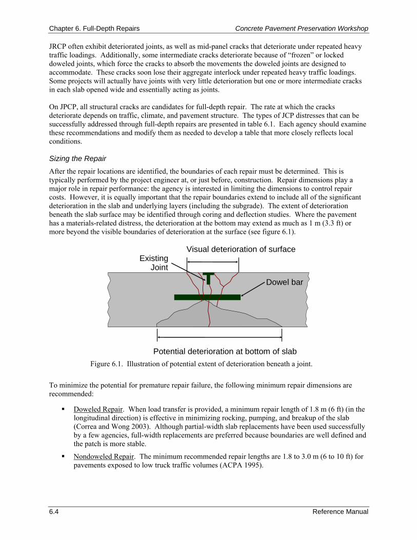
Chapter 6. Full-Depth Repairs Concrete Pavement Preservation Workshop
6.4 Reference Manual
Potential deterioration at bottom of slab
Visual deterioration of surface
Dowel bar
ExistingJoint
JRCP often exhibit deteriorated joints, as well as mid-panel cracks that deteriorate under repeated heavy traffic loadings. Additionally, some intermediate cracks deteriorate because of “frozen” or locked doweled joints, which force the cracks to absorb the movements the doweled joints are designed to accommodate. These cracks soon lose their aggregate interlock under repeated heavy traffic loadings. Some projects will actually have joints with very little deterioration but one or more intermediate cracks in each slab opened wide and essentially acting as joints. On JPCP, all structural cracks are candidates for full-depth repair. The rate at which the cracks deteriorate depends on traffic, climate, and pavement structure. The types of JCP distresses that can be successfully addressed through full-depth repairs are presented in table 6.1. Each agency should examine these recommendations and modify them as needed to develop a table that more closely reflects local conditions. Sizing the Repair
After the repair locations are identified, the boundaries of each repair must be determined. This is typically performed by the project engineer at, or just before, construction. Repair dimensions play a major role in repair performance: the agency is interested in limiting the dimensions to control repair costs. However, it is equally important that the repair boundaries extend to include all of the significant deterioration in the slab and underlying layers (including the subgrade). The extent of deterioration beneath the slab surface may be identified through coring and deflection studies. Where the pavement has a materials-related distress, the deterioration at the bottom may extend as much as 1 m (3.3 ft) or more beyond the visible boundaries of deterioration at the surface (see figure 6.1).
Figure 6.1. Illustration of potential extent of deterioration beneath a joint.
To minimize the potential for premature repair failure, the following minimum repair dimensions are recommended:
Doweled Repair. When load transfer is provided, a minimum repair length of 1.8 m (6 ft) (in the longitudinal direction) is effective in minimizing rocking, pumping, and breakup of the slab (Correa and Wong 2003). Although partial-width slab replacements have been used successfully by a few agencies, full-width replacements are preferred because boundaries are well defined and the patch is more stable.
Nondoweled Repair. The minimum recommended repair lengths are 1.8 to 3.0 m (6 to 10 ft) for pavements exposed to low truck traffic volumes (ACPA 1995).
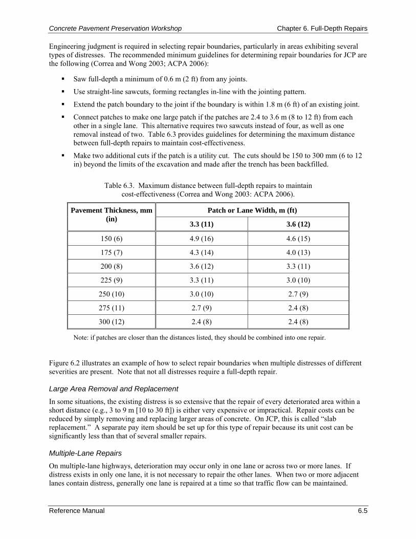
Concrete Pavement Preservation Workshop Chapter 6. Full-Depth Repairs
Reference Manual 6.5
Engineering judgment is required in selecting repair boundaries, particularly in areas exhibiting several types of distresses. The recommended minimum guidelines for determining repair boundaries for JCP are the following (Correa and Wong 2003; ACPA 2006):
Saw full-depth a minimum of 0.6 m (2 ft) from any joints.
Use straight-line sawcuts, forming rectangles in-line with the jointing pattern.
Extend the patch boundary to the joint if the boundary is within 1.8 m (6 ft) of an existing joint.
Connect patches to make one large patch if the patches are 2.4 to 3.6 m (8 to 12 ft) from each other in a single lane. This alternative requires two sawcuts instead of four, as well as one removal instead of two. Table 6.3 provides guidelines for determining the maximum distance between full-depth repairs to maintain cost-effectiveness.
Make two additional cuts if the patch is a utility cut. The cuts should be 150 to 300 mm (6 to 12 in) beyond the limits of the excavation and made after the trench has been backfilled.
Table 6.3. Maximum distance between full-depth repairs to maintain
cost-effectiveness (Correa and Wong 2003: ACPA 2006).
Patch or Lane Width, m (ft) Pavement Thickness, mm (in)
3.3 (11) 3.6 (12)
150 (6) 4.9 (16) 4.6 (15)
175 (7) 4.3 (14) 4.0 (13)
200 (8) 3.6 (12) 3.3 (11)
225 (9) 3.3 (11) 3.0 (10)
250 (10) 3.0 (10) 2.7 (9)
275 (11) 2.7 (9) 2.4 (8)
300 (12) 2.4 (8) 2.4 (8)
Note: if patches are closer than the distances listed, they should be combined into one repair. Figure 6.2 illustrates an example of how to select repair boundaries when multiple distresses of different severities are present. Note that not all distresses require a full-depth repair. Large Area Removal and Replacement
In some situations, the existing distress is so extensive that the repair of every deteriorated area within a short distance (e.g., 3 to 9 m [10 to 30 ft]) is either very expensive or impractical. Repair costs can be reduced by simply removing and replacing larger areas of concrete. On JCP, this is called “slab replacement.” A separate pay item should be set up for this type of repair because its unit cost can be significantly less than that of several smaller repairs. Multiple-Lane Repairs
On multiple-lane highways, deterioration may occur only in one lane or across two or more lanes. If distress exists in only one lane, it is not necessary to repair the other lanes. When two or more adjacent lanes contain distress, generally one lane is repaired at a time so that traffic flow can be maintained.
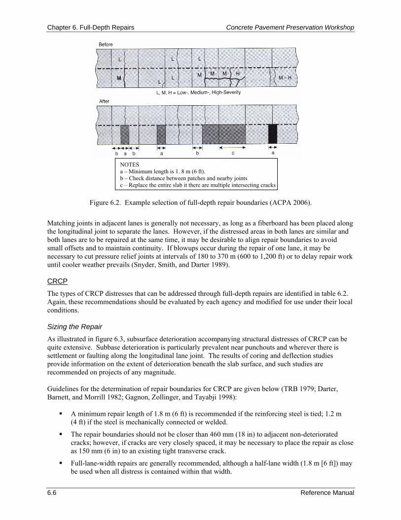
Chapter 6. Full-Depth Repairs Concrete Pavement Preservation Workshop
6.6 Reference Manual
Figure 6.2. Example selection of full-depth repair boundaries (ACPA 2006).
Matching joints in adjacent lanes is generally not necessary, as long as a fiberboard has been placed along the longitudinal joint to separate the lanes. However, if the distressed areas in both lanes are similar and both lanes are to be repaired at the same time, it may be desirable to align repair boundaries to avoid small offsets and to maintain continuity. If blowups occur during the repair of one lane, it may be necessary to cut pressure relief joints at intervals of 180 to 370 m (600 to 1,200 ft) or to delay repair work until cooler weather prevails (Snyder, Smith, and Darter 1989). CRCP
The types of CRCP distresses that can be addressed through full-depth repairs are identified in table 6.2. Again, these recommendations should be evaluated by each agency and modified for use under their local conditions. Sizing the Repair
As illustrated in figure 6.3, subsurface deterioration accompanying structural distresses of CRCP can be quite extensive. Subbase deterioration is particularly prevalent near punchouts and wherever there is settlement or faulting along the longitudinal lane joint. The results of coring and deflection studies provide information on the extent of deterioration beneath the slab surface, and such studies are recommended on projects of any magnitude. Guidelines for the determination of repair boundaries for CRCP are given below (TRB 1979; Darter, Barnett, and Morrill 1982; Gagnon, Zollinger, and Tayabji 1998):
A minimum repair length of 1.8 m (6 ft) is recommended if the reinforcing steel is tied; 1.2 m (4 ft) if the steel is mechanically connected or welded.
The repair boundaries should not be closer than 460 mm (18 in) to adjacent non-deteriorated cracks; however, if cracks are very closely spaced, it may be necessary to place the repair as close as 150 mm (6 in) to an existing tight transverse crack.
Full-lane-width repairs are generally recommended, although a half-lane width (1.8 m [6 ft]) may be used when all distress is contained within that width.
NOTES a – Minimum length is 1. 8 m (6 ft). b – Check distance between patches and nearby joints c – Replace the entire slab it there are multiple intersecting cracks
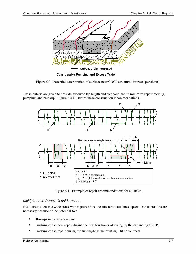
Concrete Pavement Preservation Workshop Chapter 6. Full-Depth Repairs
Reference Manual 6.7
Considerable Pumping and Excess Water
Subbase Disintegrated
Considerable Pumping and Excess Water
Subbase Disintegrated
Figure 6.3. Potential deterioration of subbase near CRCP structural distress (punchout).
These criteria are given to provide adequate lap length and cleanout, and to minimize repair rocking, pumping, and breakup. Figure 6.4 illustrates these construction recommendations.
a > 1.8 m tied steela > 1.2 m welded or mechanical connectionb > 0.46 m
1 ft = 0.305 m1 in = 25.4 mm
H
H H M
b a bReplace as a single area
b a b b a bb a b>1.8 m
H
a > 1.8 m tied steela > 1.2 m welded or mechanical connectionb > 0.46 m
1 ft = 0.305 m1 in = 25.4 mm
H
H H M
b a bReplace as a single area
b a b b a bb a b>1.8 m
H
Figure 6.4. Example of repair recommendations for a CRCP.
Multiple-Lane Repair Considerations
If a distress such as a wide crack with ruptured steel occurs across all lanes, special considerations are necessary because of the potential for:
Blowups in the adjacent lane.
Crushing of the new repair during the first few hours of curing by the expanding CRCP.
Cracking of the repair during the first night as the existing CRCP contracts.
NOTES a > 1.8 m (6 ft) tied steel a > 1.2 m (4 ft) welded or mechanical connection b > 0.46 m (1.5 ft)
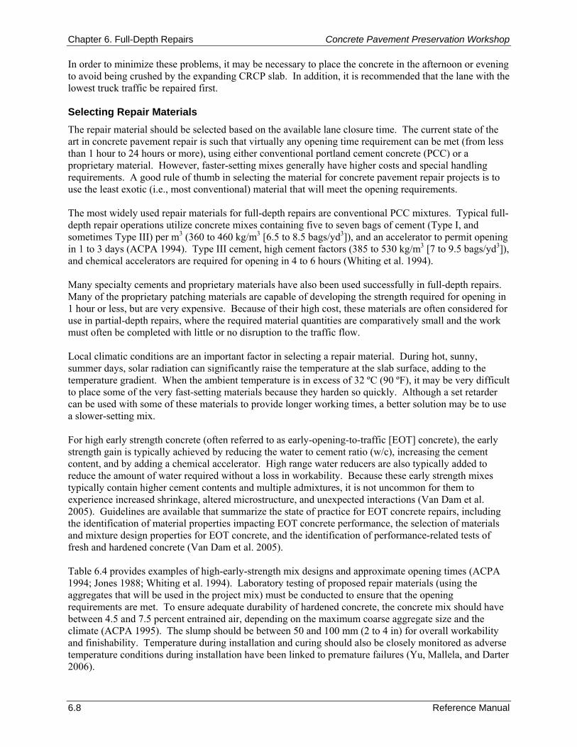
Chapter 6. Full-Depth Repairs Concrete Pavement Preservation Workshop
6.8 Reference Manual
In order to minimize these problems, it may be necessary to place the concrete in the afternoon or evening to avoid being crushed by the expanding CRCP slab. In addition, it is recommended that the lane with the lowest truck traffic be repaired first. Selecting Repair Materials The repair material should be selected based on the available lane closure time. The current state of the art in concrete pavement repair is such that virtually any opening time requirement can be met (from less than 1 hour to 24 hours or more), using either conventional portland cement concrete (PCC) or a proprietary material. However, faster-setting mixes generally have higher costs and special handling requirements. A good rule of thumb in selecting the material for concrete pavement repair projects is to use the least exotic (i.e., most conventional) material that will meet the opening requirements. The most widely used repair materials for full-depth repairs are conventional PCC mixtures. Typical full-depth repair operations utilize concrete mixes containing five to seven bags of cement (Type I, and sometimes Type III) per m3 (360 to 460 kg/m3 [6.5 to 8.5 bags/yd3]), and an accelerator to permit opening in 1 to 3 days (ACPA 1994). Type III cement, high cement factors (385 to 530 kg/m3 [7 to 9.5 bags/yd3]), and chemical accelerators are required for opening in 4 to 6 hours (Whiting et al. 1994). Many specialty cements and proprietary materials have also been used successfully in full-depth repairs. Many of the proprietary patching materials are capable of developing the strength required for opening in 1 hour or less, but are very expensive. Because of their high cost, these materials are often considered for use in partial-depth repairs, where the required material quantities are comparatively small and the work must often be completed with little or no disruption to the traffic flow. Local climatic conditions are an important factor in selecting a repair material. During hot, sunny, summer days, solar radiation can significantly raise the temperature at the slab surface, adding to the temperature gradient. When the ambient temperature is in excess of 32 ºC (90 ºF), it may be very difficult to place some of the very fast-setting materials because they harden so quickly. Although a set retarder can be used with some of these materials to provide longer working times, a better solution may be to use a slower-setting mix. For high early strength concrete (often referred to as early-opening-to-traffic [EOT] concrete), the early strength gain is typically achieved by reducing the water to cement ratio (w/c), increasing the cement content, and by adding a chemical accelerator. High range water reducers are also typically added to reduce the amount of water required without a loss in workability. Because these early strength mixes typically contain higher cement contents and multiple admixtures, it is not uncommon for them to experience increased shrinkage, altered microstructure, and unexpected interactions (Van Dam et al. 2005). Guidelines are available that summarize the state of practice for EOT concrete repairs, including the identification of material properties impacting EOT concrete performance, the selection of materials and mixture design properties for EOT concrete, and the identification of performance-related tests of fresh and hardened concrete (Van Dam et al. 2005). Table 6.4 provides examples of high-early-strength mix designs and approximate opening times (ACPA 1994; Jones 1988; Whiting et al. 1994). Laboratory testing of proposed repair materials (using the aggregates that will be used in the project mix) must be conducted to ensure that the opening requirements are met. To ensure adequate durability of hardened concrete, the concrete mix should have between 4.5 and 7.5 percent entrained air, depending on the maximum coarse aggregate size and the climate (ACPA 1995). The slump should be between 50 and 100 mm (2 to 4 in) for overall workability and finishability. Temperature during installation and curing should also be closely monitored as adverse temperature conditions during installation have been linked to premature failures (Yu, Mallela, and Darter 2006).
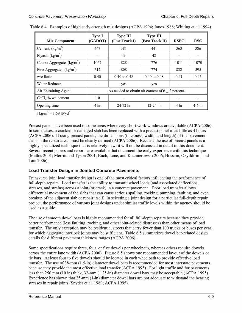
Concrete Pavement Preservation Workshop Chapter 6. Full-Depth Repairs
Reference Manual 6.9
Table 6.4. Examples of high early-strength mix designs (ACPA 1994; Jones 1988; Whiting et al. 1994).
Mix Component
Type I (GADOT)
Type III (Fast Track I)
Type III (Fast Track II) RSPC RSC
Cement, (kg/m3) 447 381 441 363 386
Flyash, (kg/m3) – 43 48 – –
Course Aggregate, (kg/m3) 1067 828 776 1011 1070
Fine Aggregate, (kg/m3) 612 808 774 832 595
w/c Ratio 0.40 0.40 to 0.48 0.40 to 0.48 0.41 0.45
Water Reducer – yes yes – –
Air Entraining Agent As needed to obtain air content of 6 + 2 percent.
CaCl2 % wt. cement 1.0 – – – –
Opening time 4 hr 24-72 hr 12-24 hr 4 hr 4-6 hr
1 kg/m3 = 1.69 lb/yd3
Precast panels have been used in some areas where very short work windows are available (ACPA 2006). In some cases, a cracked or damaged slab has been replaced with a precast panel in as little as 4 hours (ACPA 2006). If using precast panels, the dimensions (thickness, width, and length) of the pavement slabs in the repair areas must be clearly defined (ACPA 2006). Because the use of precast panels is a highly specialized technique that is relatively new, it will not be discussed in detail in this document. Several recent papers and reports are available that document the early experience with this technique (Mathis 2001; Merritt and Tyson 2001; Buch, Lane, and Kazmierowski 2006; Hossain, Ozyildirim, and Tate 2006). Load Transfer Design in Jointed Concrete Pavements Transverse joint load transfer design is one of the most critical factors influencing the performance of full-depth repairs. Load transfer is the ability to transmit wheel loads (and associated deflections, stresses, and strains) across a joint (or crack) in a concrete pavement. Poor load transfer allows differential movement of the slabs that can cause serious spalling, rocking, pumping, faulting, and even breakup of the adjacent slab or repair itself. In selecting a joint design for a particular full-depth repair project, the performance of various joint designs under similar traffic levels within the agency should be used as a guide. The use of smooth dowel bars is highly recommended for all full-depth repairs because they provide better performance (less faulting, rocking, and other joint-related distresses) than other means of load transfer. The only exception may be residential streets that carry fewer than 100 trucks or buses per year, for which aggregate interlock joints may be sufficient. Table 6.5 summarizes dowel bar-related design details for different pavement thickness ranges (ACPA 2006). Some specifications require three, four, or five dowels per wheelpath, whereas others require dowels across the entire lane width (ACPA 2006). Figure 6.5 shows one recommended layout of the dowels or tie bars. At least four to five dowels should be located in each wheelpath to provide effective load transfer. The use of 38-mm (1.5-in) diameter dowel bars is recommended for most interstate pavements because they provide the most effective load transfer (ACPA 1995). For light traffic and for pavements less than 250 mm (10 in) thick, 32-mm (1.25-in) diameter dowel bars may be acceptable (ACPA 1995). Experience has shown that 25-mm (1-in) diameter dowel bars are not adequate to withstand the bearing stresses in repair joints (Snyder et al. 1989; ACPA 1995).
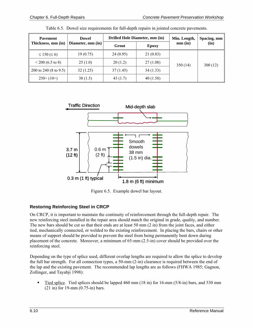
Chapter 6. Full-Depth Repairs Concrete Pavement Preservation Workshop
6.10 Reference Manual
Smoothdowels38 mm (1.5 in) dia.
3.7 m(12 ft)
0.6 m(2 ft)
0.3 m (1 ft) typical1.8 m (6 ft) minimum
Mid-depth slabTraffic Direction
Smoothdowels38 mm (1.5 in) dia.
3.7 m(12 ft)
0.6 m(2 ft)
0.3 m (1 ft) typical1.8 m (6 ft) minimum
Mid-depth slabTraffic Direction
Table 6.5. Dowel size requirements for full-depth repairs in jointed concrete pavements.
Drilled Hole Diameter, mm (in) Pavement Thickness, mm (in)
Dowel Diameter, mm (in) Grout Epoxy
Min. Length, mm (in)
Spacing, mm (in)
≤ 150 (≤ 6) 19 (0.75) 24 (0.95) 21 (0.83)
< 200 (6.5 to 8) 25 (1.0) 20 (1.2) 27 (1.08)
200 to 240 (8 to 9.5) 32 (1.25) 37 (1.45) 34 (1.33)
250+ (10+) 38 (1.5) 43 (1.7) 40 (1.58)
350 (14) 300 (12)
Figure 6.5. Example dowel bar layout. Restoring Reinforcing Steel in CRCP On CRCP, it is important to maintain the continuity of reinforcement through the full-depth repair. The new reinforcing steel installed in the repair area should match the original in grade, quality, and number. The new bars should be cut so that their ends are at least 50 mm (2 in) from the joint faces, and either tied, mechanically connected, or welded to the existing reinforcement. In placing the bars, chairs or other means of support should be provided to prevent the steel from being permanently bent down during placement of the concrete. Moreover, a minimum of 65-mm (2.5-in) cover should be provided over the reinforcing steel. Depending on the type of splice used, different overlap lengths are required to allow the splice to develop the full bar strength. For all connection types, a 50-mm (2-in) clearance is required between the end of the lap and the existing pavement. The recommended lap lengths are as follows (FHWA 1985; Gagnon, Zollinger, and Tayabji 1998):
Tied splice. Tied splices should be lapped 460 mm (18 in) for 16-mm (5/8-in) bars, and 530 mm (21 in) for 19-mm (0.75-in) bars.
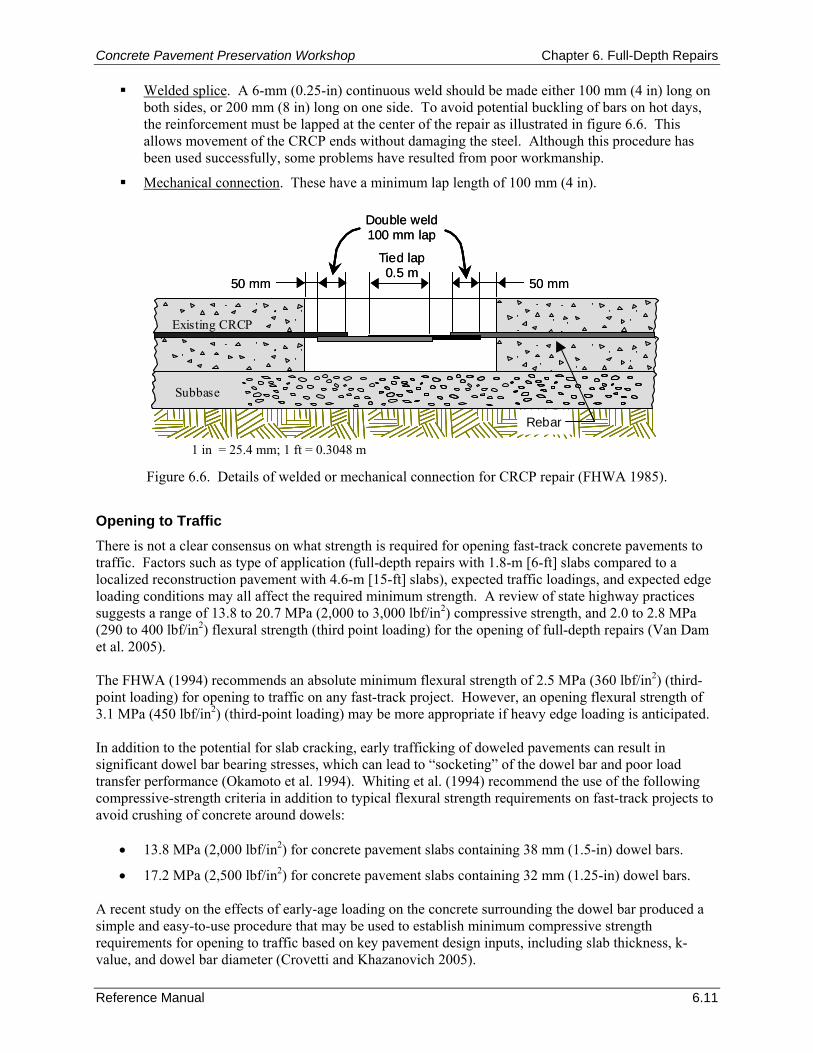
Concrete Pavement Preservation Workshop Chapter 6. Full-Depth Repairs
Reference Manual 6.11
Welded splice. A 6-mm (0.25-in) continuous weld should be made either 100 mm (4 in) long on both sides, or 200 mm (8 in) long on one side. To avoid potential buckling of bars on hot days, the reinforcement must be lapped at the center of the repair as illustrated in figure 6.6. This allows movement of the CRCP ends without damaging the steel. Although this procedure has been used successfully, some problems have resulted from poor workmanship.
Mechanical connection. These have a minimum lap length of 100 mm (4 in).
Tied lap0.5 m
Rebar
50 mm 50 mm
Double weld100 mm lap
Existing CRCP
Subbase
Tied lap0.5 m
Rebar
50 mm 50 mm
Double weld100 mm lap
Existing CRCP
SubbaseSubbase
1 in = 25.4 mm; 1 ft = 0.3048 m
Figure 6.6. Details of welded or mechanical connection for CRCP repair (FHWA 1985).
Opening to Traffic There is not a clear consensus on what strength is required for opening fast-track concrete pavements to traffic. Factors such as type of application (full-depth repairs with 1.8-m [6-ft] slabs compared to a localized reconstruction pavement with 4.6-m [15-ft] slabs), expected traffic loadings, and expected edge loading conditions may all affect the required minimum strength. A review of state highway practices suggests a range of 13.8 to 20.7 MPa (2,000 to 3,000 lbf/in2) compressive strength, and 2.0 to 2.8 MPa (290 to 400 lbf/in2) flexural strength (third point loading) for the opening of full-depth repairs (Van Dam et al. 2005). The FHWA (1994) recommends an absolute minimum flexural strength of 2.5 MPa (360 lbf/in2) (third-point loading) for opening to traffic on any fast-track project. However, an opening flexural strength of 3.1 MPa (450 lbf/in2) (third-point loading) may be more appropriate if heavy edge loading is anticipated. In addition to the potential for slab cracking, early trafficking of doweled pavements can result in significant dowel bar bearing stresses, which can lead to “socketing” of the dowel bar and poor load transfer performance (Okamoto et al. 1994). Whiting et al. (1994) recommend the use of the following compressive-strength criteria in addition to typical flexural strength requirements on fast-track projects to avoid crushing of concrete around dowels:
• 13.8 MPa (2,000 lbf/in2) for concrete pavement slabs containing 38 mm (1.5-in) dowel bars.
• 17.2 MPa (2,500 lbf/in2) for concrete pavement slabs containing 32 mm (1.25-in) dowel bars. A recent study on the effects of early-age loading on the concrete surrounding the dowel bar produced a simple and easy-to-use procedure that may be used to establish minimum compressive strength requirements for opening to traffic based on key pavement design inputs, including slab thickness, k-value, and dowel bar diameter (Crovetti and Khazanovich 2005).
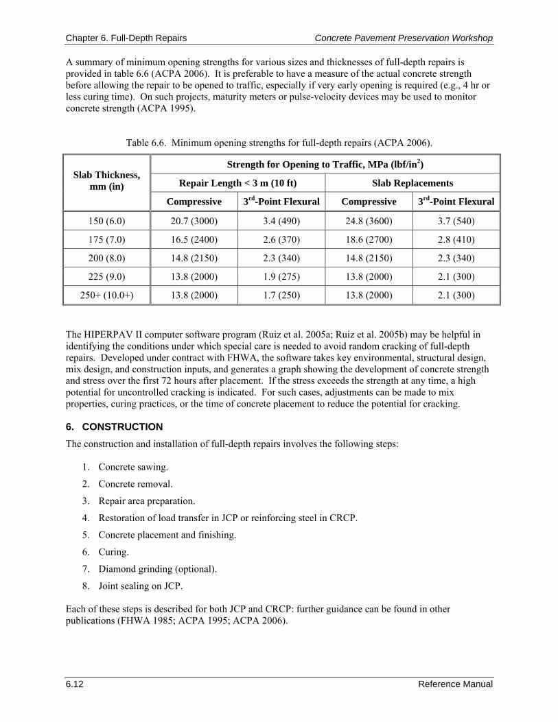
Chapter 6. Full-Depth Repairs Concrete Pavement Preservation Workshop
6.12 Reference Manual
A summary of minimum opening strengths for various sizes and thicknesses of full-depth repairs is provided in table 6.6 (ACPA 2006). It is preferable to have a measure of the actual concrete strength before allowing the repair to be opened to traffic, especially if very early opening is required (e.g., 4 hr or less curing time). On such projects, maturity meters or pulse-velocity devices may be used to monitor concrete strength (ACPA 1995).
Table 6.6. Minimum opening strengths for full-depth repairs (ACPA 2006).
Strength for Opening to Traffic, MPa (lbf/in2)
Repair Length < 3 m (10 ft) Slab Replacements Slab Thickness,
mm (in) Compressive 3rd-Point Flexural Compressive 3rd-Point Flexural
150 (6.0) 20.7 (3000) 3.4 (490) 24.8 (3600) 3.7 (540)
175 (7.0) 16.5 (2400) 2.6 (370) 18.6 (2700) 2.8 (410)
200 (8.0) 14.8 (2150) 2.3 (340) 14.8 (2150) 2.3 (340)
225 (9.0) 13.8 (2000) 1.9 (275) 13.8 (2000) 2.1 (300)
250+ (10.0+) 13.8 (2000) 1.7 (250) 13.8 (2000) 2.1 (300) The HIPERPAV II computer software program (Ruiz et al. 2005a; Ruiz et al. 2005b) may be helpful in identifying the conditions under which special care is needed to avoid random cracking of full-depth repairs. Developed under contract with FHWA, the software takes key environmental, structural design, mix design, and construction inputs, and generates a graph showing the development of concrete strength and stress over the first 72 hours after placement. If the stress exceeds the strength at any time, a high potential for uncontrolled cracking is indicated. For such cases, adjustments can be made to mix properties, curing practices, or the time of concrete placement to reduce the potential for cracking. 6. CONSTRUCTION The construction and installation of full-depth repairs involves the following steps:
1. Concrete sawing.
2. Concrete removal.
3. Repair area preparation.
4. Restoration of load transfer in JCP or reinforcing steel in CRCP.
5. Concrete placement and finishing.
6. Curing.
7. Diamond grinding (optional).
8. Joint sealing on JCP. Each of these steps is described for both JCP and CRCP: further guidance can be found in other publications (FHWA 1985; ACPA 1995; ACPA 2006).
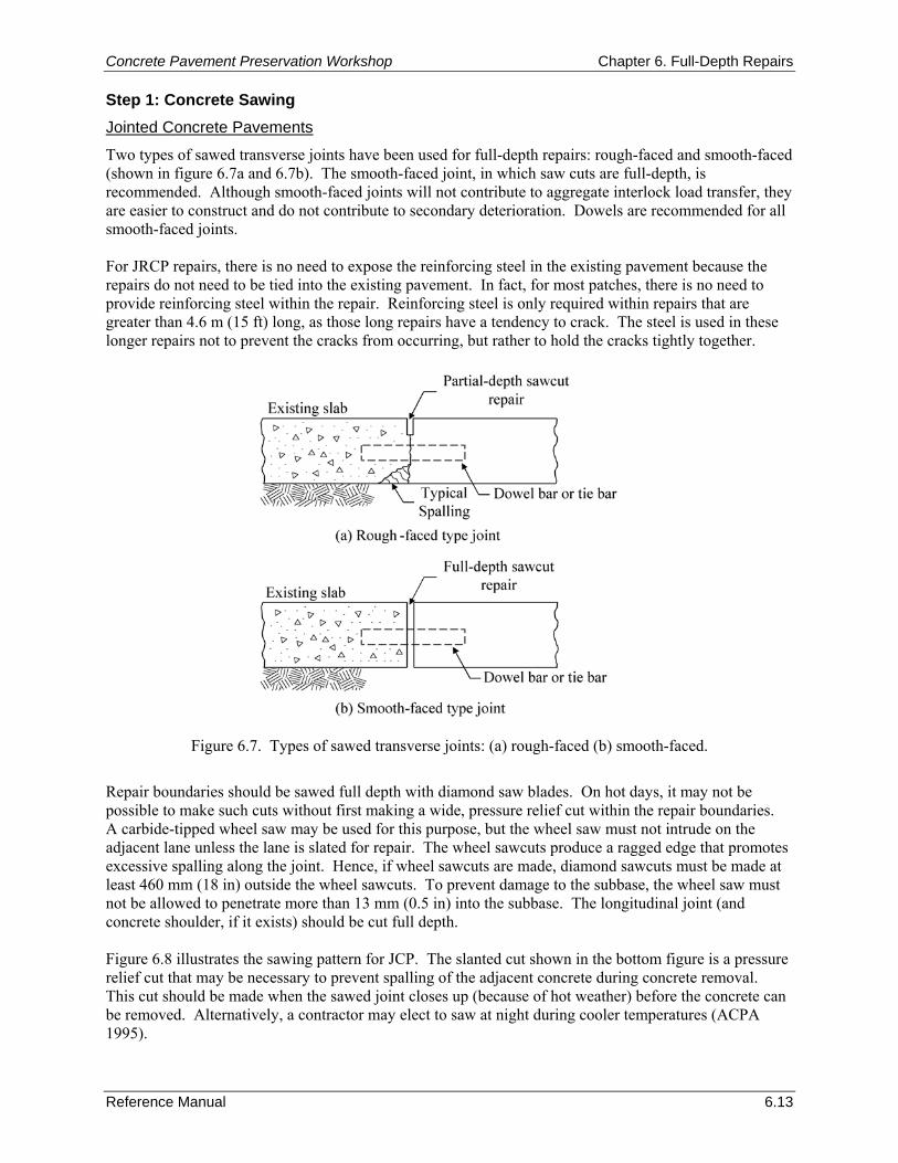
Concrete Pavement Preservation Workshop Chapter 6. Full-Depth Repairs
Reference Manual 6.13
Step 1: Concrete Sawing Jointed Concrete Pavements
Two types of sawed transverse joints have been used for full-depth repairs: rough-faced and smooth-faced (shown in figure 6.7a and 6.7b). The smooth-faced joint, in which saw cuts are full-depth, is recommended. Although smooth-faced joints will not contribute to aggregate interlock load transfer, they are easier to construct and do not contribute to secondary deterioration. Dowels are recommended for all smooth-faced joints. For JRCP repairs, there is no need to expose the reinforcing steel in the existing pavement because the repairs do not need to be tied into the existing pavement. In fact, for most patches, there is no need to provide reinforcing steel within the repair. Reinforcing steel is only required within repairs that are greater than 4.6 m (15 ft) long, as those long repairs have a tendency to crack. The steel is used in these longer repairs not to prevent the cracks from occurring, but rather to hold the cracks tightly together.
Figure 6.7. Types of sawed transverse joints: (a) rough-faced (b) smooth-faced.
Repair boundaries should be sawed full depth with diamond saw blades. On hot days, it may not be possible to make such cuts without first making a wide, pressure relief cut within the repair boundaries. A carbide-tipped wheel saw may be used for this purpose, but the wheel saw must not intrude on the adjacent lane unless the lane is slated for repair. The wheel sawcuts produce a ragged edge that promotes excessive spalling along the joint. Hence, if wheel sawcuts are made, diamond sawcuts must be made at least 460 mm (18 in) outside the wheel sawcuts. To prevent damage to the subbase, the wheel saw must not be allowed to penetrate more than 13 mm (0.5 in) into the subbase. The longitudinal joint (and concrete shoulder, if it exists) should be cut full depth. Figure 6.8 illustrates the sawing pattern for JCP. The slanted cut shown in the bottom figure is a pressure relief cut that may be necessary to prevent spalling of the adjacent concrete during concrete removal. This cut should be made when the sawed joint closes up (because of hot weather) before the concrete can be removed. Alternatively, a contractor may elect to saw at night during cooler temperatures (ACPA 1995).
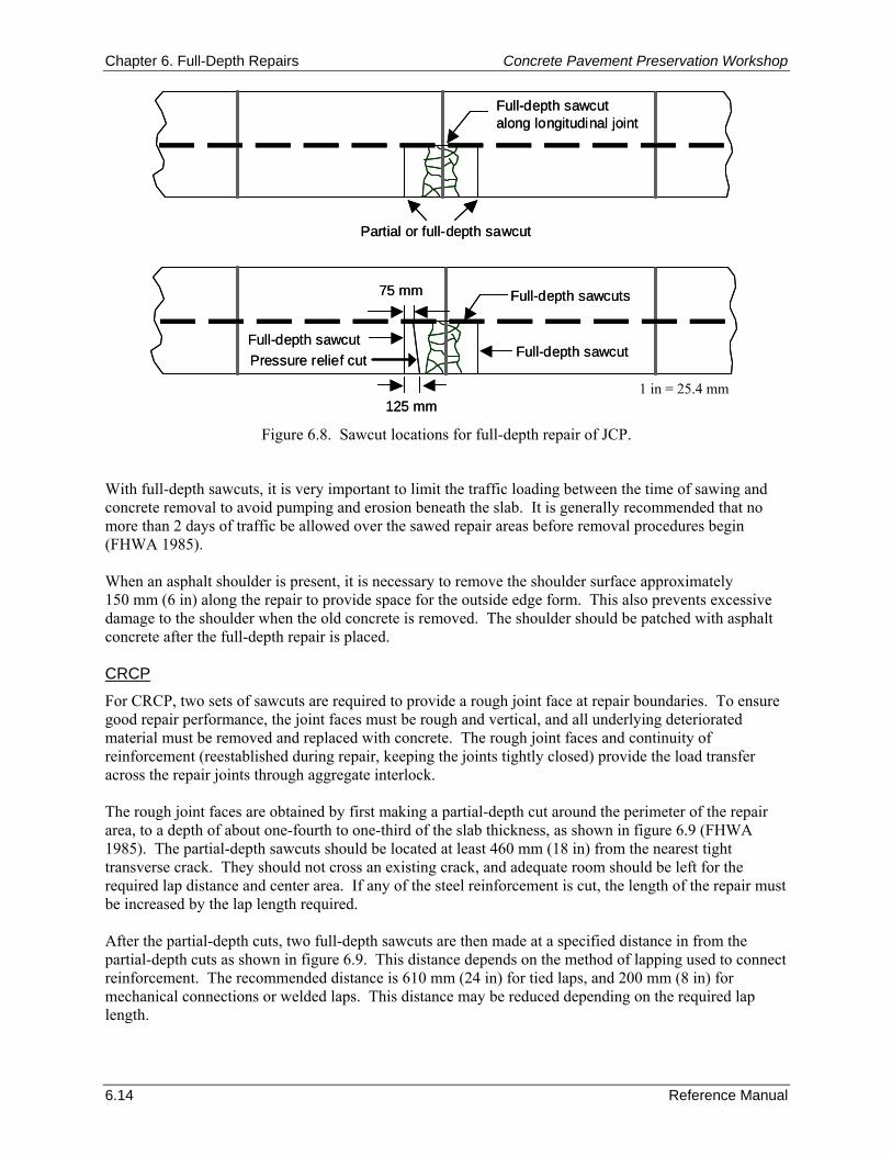
Chapter 6. Full-Depth Repairs Concrete Pavement Preservation Workshop
6.14 Reference Manual
Full-depth sawcutalong longitudinal joint
Partial or full-depth sawcut
Full-depth sawcuts
Full-depth sawcutFull-depth sawcut
125 mm
75 mm
Pressure relief cut
Full-depth sawcutalong longitudinal joint
Partial or full-depth sawcut
Full-depth sawcuts
Full-depth sawcutFull-depth sawcut
125 mm
75 mm
Pressure relief cut
Figure 6.8. Sawcut locations for full-depth repair of JCP.
With full-depth sawcuts, it is very important to limit the traffic loading between the time of sawing and concrete removal to avoid pumping and erosion beneath the slab. It is generally recommended that no more than 2 days of traffic be allowed over the sawed repair areas before removal procedures begin (FHWA 1985). When an asphalt shoulder is present, it is necessary to remove the shoulder surface approximately 150 mm (6 in) along the repair to provide space for the outside edge form. This also prevents excessive damage to the shoulder when the old concrete is removed. The shoulder should be patched with asphalt concrete after the full-depth repair is placed. CRCP
For CRCP, two sets of sawcuts are required to provide a rough joint face at repair boundaries. To ensure good repair performance, the joint faces must be rough and vertical, and all underlying deteriorated material must be removed and replaced with concrete. The rough joint faces and continuity of reinforcement (reestablished during repair, keeping the joints tightly closed) provide the load transfer across the repair joints through aggregate interlock. The rough joint faces are obtained by first making a partial-depth cut around the perimeter of the repair area, to a depth of about one-fourth to one-third of the slab thickness, as shown in figure 6.9 (FHWA 1985). The partial-depth sawcuts should be located at least 460 mm (18 in) from the nearest tight transverse crack. They should not cross an existing crack, and adequate room should be left for the required lap distance and center area. If any of the steel reinforcement is cut, the length of the repair must be increased by the lap length required. After the partial-depth cuts, two full-depth sawcuts are then made at a specified distance in from the partial-depth cuts as shown in figure 6.9. This distance depends on the method of lapping used to connect reinforcement. The recommended distance is 610 mm (24 in) for tied laps, and 200 mm (8 in) for mechanical connections or welded laps. This distance may be reduced depending on the required lap length.
1 in = 25.4 mm
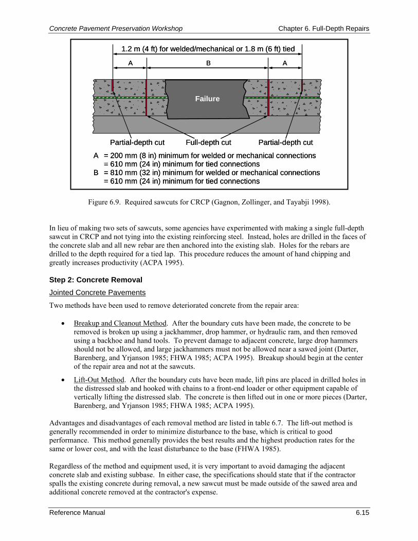
Concrete Pavement Preservation Workshop Chapter 6. Full-Depth Repairs
Reference Manual 6.15
A = 200 mm (8 in) minimum for welded or mechanical connections= 610 mm (24 in) minimum for tied connections
B = 810 mm (32 in) minimum for welded or mechanical connections= 610 mm (24 in) minimum for tied connections
1.2 m (4 ft) for welded/mechanical or 1.8 m (6 ft) tied
Full-depth cutPartial-depth cut
Failure
A
Partial-depth cut
B A
Figure 6.9. Required sawcuts for CRCP (Gagnon, Zollinger, and Tayabji 1998). In lieu of making two sets of sawcuts, some agencies have experimented with making a single full-depth sawcut in CRCP and not tying into the existing reinforcing steel. Instead, holes are drilled in the faces of the concrete slab and all new rebar are then anchored into the existing slab. Holes for the rebars are drilled to the depth required for a tied lap. This procedure reduces the amount of hand chipping and greatly increases productivity (ACPA 1995). Step 2: Concrete Removal Jointed Concrete Pavements
Two methods have been used to remove deteriorated concrete from the repair area:
• Breakup and Cleanout Method. After the boundary cuts have been made, the concrete to be removed is broken up using a jackhammer, drop hammer, or hydraulic ram, and then removed using a backhoe and hand tools. To prevent damage to adjacent concrete, large drop hammers should not be allowed, and large jackhammers must not be allowed near a sawed joint (Darter, Barenberg, and Yrjanson 1985; FHWA 1985; ACPA 1995). Breakup should begin at the center of the repair area and not at the sawcuts.
• Lift-Out Method. After the boundary cuts have been made, lift pins are placed in drilled holes in the distressed slab and hooked with chains to a front-end loader or other equipment capable of vertically lifting the distressed slab. The concrete is then lifted out in one or more pieces (Darter, Barenberg, and Yrjanson 1985; FHWA 1985; ACPA 1995).
Advantages and disadvantages of each removal method are listed in table 6.7. The lift-out method is generally recommended in order to minimize disturbance to the base, which is critical to good performance. This method generally provides the best results and the highest production rates for the same or lower cost, and with the least disturbance to the base (FHWA 1985). Regardless of the method and equipment used, it is very important to avoid damaging the adjacent concrete slab and existing subbase. In either case, the specifications should state that if the contractor spalls the existing concrete during removal, a new sawcut must be made outside of the sawed area and additional concrete removed at the contractor's expense.
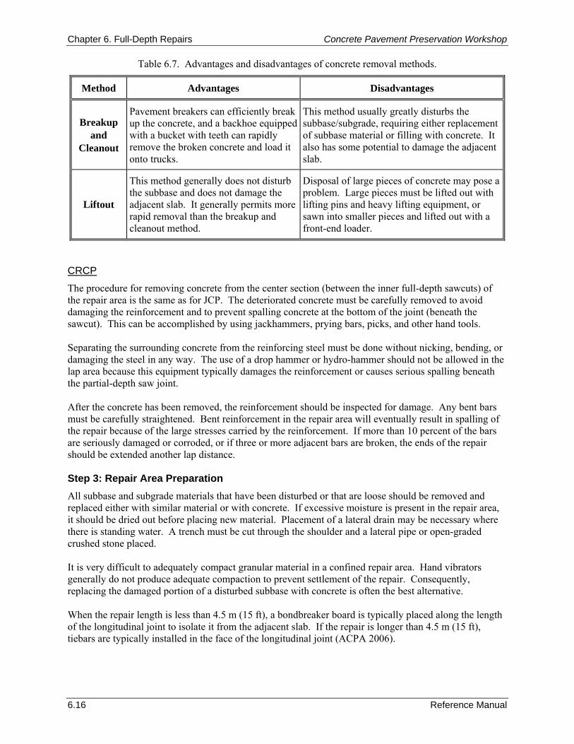
Chapter 6. Full-Depth Repairs Concrete Pavement Preservation Workshop
6.16 Reference Manual
Table 6.7. Advantages and disadvantages of concrete removal methods.
Method Advantages Disadvantages
Breakup and
Cleanout
Pavement breakers can efficiently break up the concrete, and a backhoe equipped with a bucket with teeth can rapidly remove the broken concrete and load it onto trucks.
This method usually greatly disturbs the subbase/subgrade, requiring either replacement of subbase material or filling with concrete. It also has some potential to damage the adjacent slab.
Liftout
This method generally does not disturb the subbase and does not damage the adjacent slab. It generally permits more rapid removal than the breakup and cleanout method.
Disposal of large pieces of concrete may pose a problem. Large pieces must be lifted out with lifting pins and heavy lifting equipment, or sawn into smaller pieces and lifted out with a front-end loader.
CRCP
The procedure for removing concrete from the center section (between the inner full-depth sawcuts) of the repair area is the same as for JCP. The deteriorated concrete must be carefully removed to avoid damaging the reinforcement and to prevent spalling concrete at the bottom of the joint (beneath the sawcut). This can be accomplished by using jackhammers, prying bars, picks, and other hand tools. Separating the surrounding concrete from the reinforcing steel must be done without nicking, bending, or damaging the steel in any way. The use of a drop hammer or hydro-hammer should not be allowed in the lap area because this equipment typically damages the reinforcement or causes serious spalling beneath the partial-depth saw joint. After the concrete has been removed, the reinforcement should be inspected for damage. Any bent bars must be carefully straightened. Bent reinforcement in the repair area will eventually result in spalling of the repair because of the large stresses carried by the reinforcement. If more than 10 percent of the bars are seriously damaged or corroded, or if three or more adjacent bars are broken, the ends of the repair should be extended another lap distance. Step 3: Repair Area Preparation All subbase and subgrade materials that have been disturbed or that are loose should be removed and replaced either with similar material or with concrete. If excessive moisture is present in the repair area, it should be dried out before placing new material. Placement of a lateral drain may be necessary where there is standing water. A trench must be cut through the shoulder and a lateral pipe or open-graded crushed stone placed. It is very difficult to adequately compact granular material in a confined repair area. Hand vibrators generally do not produce adequate compaction to prevent settlement of the repair. Consequently, replacing the damaged portion of a disturbed subbase with concrete is often the best alternative. When the repair length is less than 4.5 m (15 ft), a bondbreaker board is typically placed along the length of the longitudinal joint to isolate it from the adjacent slab. If the repair is longer than 4.5 m (15 ft), tiebars are typically installed in the face of the longitudinal joint (ACPA 2006).
Concrete Pavement Preservation Workshop Chapter 6. Full-Depth Repairs
Reference Manual 6.17
Step 4: Restoration of Load Transfer in JCP or Reinforcing Steel in CRCP Restoring Load Transfer in Jointed Concrete Pavements
Smooth, steel dowel bars are recommended for load transfer at both repair joints to allow uninhibited horizontal movement. The dowels are installed by drilling holes on 300-mm (12-in) centers at mid-depth of the exposed face of the existing slab. Tractor-mounted gang drills can be used to drill several holes simultaneously, while maintaining proper horizontal and vertical alignment (ACPA 1995). Single hand-held drills are not recommended because of the likelihood of misalignment (Darter, Barenberg, and Yrjanson 1985). The dowel holes must be drilled slightly larger than the dowel diameter to allow room for the anchoring material. If a cement grout is used, the hole diameter should be 5 to 6 mm (0.2 to 0.25 in) larger than the dowel diameter (ACPA 2006). A plastic grout mixture provides better support for dowels than a very fluid mixture. If an epoxy mortar is used, the hole diameter should be no more than 2 mm (0.06 in) larger than the dowel diameter, because this type of material can often ooze out through small gaps. Anchoring the dowels into the existing slab is a critical construction step. Studies have shown that poor dowel embedment procedures often result in poor performance of the repair, because of spalling and faulting caused by movement of the dowels (Snyder et al. 1989). The following procedure is recommended for anchoring dowel bars (Snyder et al. 1989; FHWA 1985; ACPA 1995):
1. Remove debris and dust from the dowel holes by blowing them out with air. If the holes are wet, they should be allowed to dry before installing dowels. Check dowel holes for cleanliness before proceeding.
2. Place quick-setting, non-shrinking cement grout or epoxy resin in the back of the dowel hole. Cement grout is placed by using a flexible tube with a long nose that places the material in the back of the hole. Epoxy-type materials are placed using a cartridge with a long nozzle that dispenses the material to the rear of the hole.
3. Insert the dowel into the hole with a slight twisting motion so that the material in the back of the hole is forced up and around the dowel bar. This ensures a uniform coating of the anchoring material over the dowel bar.
4. Optionally, place a grout retention disk (a thin donut-shaped plastic disk) over the dowel and against the slab face, as illustrated in figure 6.10. This prevents the anchoring material from flowing out of the hole and helps create an effective face at the entrance of the dowel hole (the location of the critical bearing stress).
After placement, the protruding end of the dowels should be lightly greased to facilitate movement. If steel reinforcement is to be provided within the repair (typically in longer repairs), the steel should be placed between concrete lifts with a minimum of 75-mm (3-in) cover and 65-mm (2.5-in) edge clearance. Restoring Reinforcing Steel in CRCP
As mentioned previously, the continuity of reinforcement must be maintained through full-depth repairs. The splicing of the reinforcement bars should be conducted using the detailed design information presented in the Design and Materials Considerations section. Step 5: Concrete Placement and Finishing Critical aspects of concrete placement and finishing for full-depth repairs include attaining adequate consolidation and a level finish with the surrounding concrete (Darter, Barenberg, and Yrjanson 1985; Snyder et al. 1989). Special attention should be given to ensure that the concrete is well vibrated around the edges of the repair and that it is not over-finished. Ambient temperatures should be between 4 and 32 °C (40 and 90 °F) for any concrete placement (ACPA 2006).
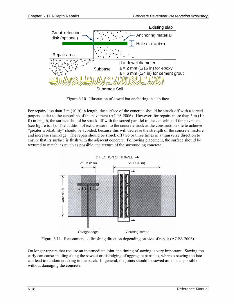
Chapter 6. Full-Depth Repairs Concrete Pavement Preservation Workshop
6.18 Reference Manual
Figure 6.10. Illustration of dowel bar anchoring in slab face.
For repairs less than 3 m (10 ft) in length, the surface of the concrete should be struck off with a screed perpendicular to the centerline of the pavement (ACPA 2006). However, for repairs more than 3 m (10 ft) in length, the surface should be struck off with the screed parallel to the centerline of the pavement (see figure 6.11). The addition of extra water into the concrete truck at the construction site to achieve “greater workability” should be avoided, because this will decrease the strength of the concrete mixture and increase shrinkage. The repair should be struck off two or three times in a transverse direction to ensure that its surface is flush with the adjacent concrete. Following placement, the surface should be textured to match, as much as possible, the texture of the surrounding concrete.
Figure 6.11. Recommended finishing direction depending on size of repair (ACPA 2006).
On longer repairs that require an intermediate joint, the timing of sawing is very important. Sawing too early can cause spalling along the sawcut or dislodging of aggregate particles, whereas sawing too late can lead to random cracking in the patch. In general, the joints should be sawed as soon as possible without damaging the concrete.
Subbase
Repair area
Anchoring material Grout - retentiondisk (optional)
Hole dia. = d+a
Existing slab
a = 2 mm (1/16 in) for epoxy a = 6 mm (1/4 in) for cement grout
d = dowel diameter
Subgrade Soil
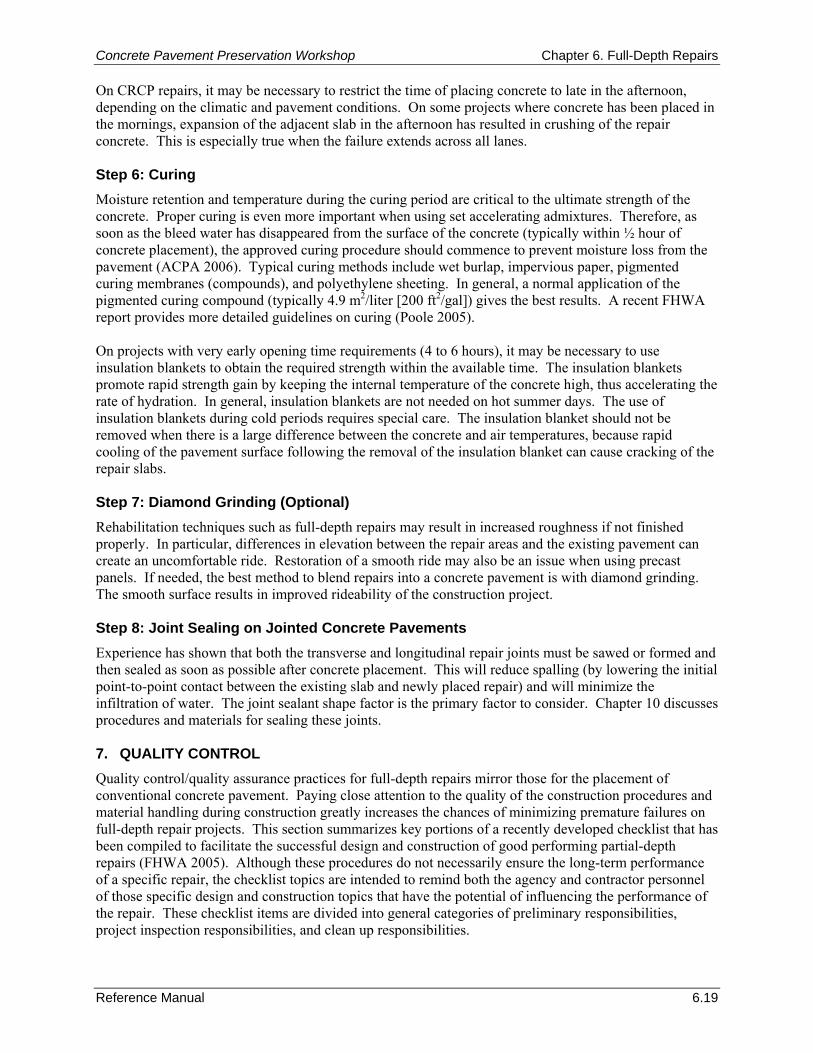
Concrete Pavement Preservation Workshop Chapter 6. Full-Depth Repairs
Reference Manual 6.19
On CRCP repairs, it may be necessary to restrict the time of placing concrete to late in the afternoon, depending on the climatic and pavement conditions. On some projects where concrete has been placed in the mornings, expansion of the adjacent slab in the afternoon has resulted in crushing of the repair concrete. This is especially true when the failure extends across all lanes. Step 6: Curing Moisture retention and temperature during the curing period are critical to the ultimate strength of the concrete. Proper curing is even more important when using set accelerating admixtures. Therefore, as soon as the bleed water has disappeared from the surface of the concrete (typically within ½ hour of concrete placement), the approved curing procedure should commence to prevent moisture loss from the pavement (ACPA 2006). Typical curing methods include wet burlap, impervious paper, pigmented curing membranes (compounds), and polyethylene sheeting. In general, a normal application of the pigmented curing compound (typically 4.9 m2/liter [200 ft2/gal]) gives the best results. A recent FHWA report provides more detailed guidelines on curing (Poole 2005). On projects with very early opening time requirements (4 to 6 hours), it may be necessary to use insulation blankets to obtain the required strength within the available time. The insulation blankets promote rapid strength gain by keeping the internal temperature of the concrete high, thus accelerating the rate of hydration. In general, insulation blankets are not needed on hot summer days. The use of insulation blankets during cold periods requires special care. The insulation blanket should not be removed when there is a large difference between the concrete and air temperatures, because rapid cooling of the pavement surface following the removal of the insulation blanket can cause cracking of the repair slabs. Step 7: Diamond Grinding (Optional) Rehabilitation techniques such as full-depth repairs may result in increased roughness if not finished properly. In particular, differences in elevation between the repair areas and the existing pavement can create an uncomfortable ride. Restoration of a smooth ride may also be an issue when using precast panels. If needed, the best method to blend repairs into a concrete pavement is with diamond grinding. The smooth surface results in improved rideability of the construction project. Step 8: Joint Sealing on Jointed Concrete Pavements Experience has shown that both the transverse and longitudinal repair joints must be sawed or formed and then sealed as soon as possible after concrete placement. This will reduce spalling (by lowering the initial point-to-point contact between the existing slab and newly placed repair) and will minimize the infiltration of water. The joint sealant shape factor is the primary factor to consider. Chapter 10 discusses procedures and materials for sealing these joints. 7. QUALITY CONTROL Quality control/quality assurance practices for full-depth repairs mirror those for the placement of conventional concrete pavement. Paying close attention to the quality of the construction procedures and material handling during construction greatly increases the chances of minimizing premature failures on full-depth repair projects. This section summarizes key portions of a recently developed checklist that has been compiled to facilitate the successful design and construction of good performing partial-depth repairs (FHWA 2005). Although these procedures do not necessarily ensure the long-term performance of a specific repair, the checklist topics are intended to remind both the agency and contractor personnel of those specific design and construction topics that have the potential of influencing the performance of the repair. These checklist items are divided into general categories of preliminary responsibilities, project inspection responsibilities, and clean up responsibilities.

Chapter 6. Full-Depth Repairs Concrete Pavement Preservation Workshop
6.20 Reference Manual
Preliminary Responsibilities In the initial part of the QC process, agency and contractor personnel should collectively conduct a review of the project documentation, project scope and intended construction procedures, and material usage and associates specifications. Such a collective review is intended to minimize any misunderstandings in the field between agency designers, inspectors, and construction personnel. Specific checklist items for this review are summarized below. Document Review
As a first step, review the following project-related documents:
Bid/project specifications and design.
Applicable special provisions.
Traffic control plan.
Manufacturer’s specific installation instructions for chosen patch material(s).
Manufacturer’s material safety data sheets (MSDS). Project Review
In an attempt to maximize the efficiency of the field construction process, the following reviews of the project scope-related items should be conducted:
Verify that pavement conditions have not significantly changed since the project was designed and that a full-depth repair is still appropriate for the pavement.
Check that the estimated number of full-depth repairs agrees with the number specified in the contract.
Agree on quantities to be placed, but allow flexibility if additional deterioration is found below the surface.
Materials Checks
A number of material-related checks are recommended prior to the start of a full-depth repair project. Specifically, agency and contractor personnel should collectively verify that:
The concrete patch material is being produced by a supplier listed on the agency’s Approved/Qualified Supplier List as required by the contract documents.
The mix design for the material has been sampled and tested prior to installation as required by the contract documents.
The load transfer units (dowels) meet specifications and that dowels are properly coated with epoxy (or other approved material) and free of any minor surface damage in accordance with contract documents.
Dowel-hole cementing grout meets specifications.
Bond-breaking board meets specifications (typically asphalt-impregnated fiberboard).
Joint sealant material meets specifications.
Sufficient quantities of materials are on hand for completion of the project.
All material certifications required by contract documents have been provided to the agency prior to construction.
Concrete Pavement Preservation Workshop Chapter 6. Full-Depth Repairs
Reference Manual 6.21
Equipment Inspections
In this step, all equipment that will be utilized in the construction of full-depth repairs should be reviewed. Ensuring that construction equipment is in good working order will help avoid construction-related problems during the construction process. The following items should be checked or verified as part of the equipment inspection process prior to the start of a full-depth repair project. Concrete Removal Equipment
Verify that concrete saws and blades are in good condition and of sufficient diameter and horsepower to adequately cut the required patch boundaries as required by the contract documents.
Verify that required equipment used for concrete removal is all on-site and in proper working order and of sufficient size, weight, and horsepower to accomplish the removal process (including front-end loader, crane, fork lift, backhoe, skid steer, and jackhammers).
Patch Area Preparation Equipment
Verify that the plate compactor is working properly and capable of compacting the subbase material.
Verify that the gang drills are calibrated, aligned, and sufficiently heavy and powerful enough to drill multiple holes for dowel bars.
Verify that air compressors are equipped with and using properly functioning oil and moisture filters/traps. This can be accomplished by passing the air stream over a board, and then examining for contaminants.
Testing Equipment
Verify that the concrete testing technician meets the requirements of the contract documents for training/certification.
Ensure that material test equipment required by the specifications is all available on-site and in proper working condition (equipment typically includes slump cone, pressure-type air meter, cylinder molds and lids, rod, mallet, ruler, and 3-m [10-ft] straightedge).
Ensure that sufficient storage area on the project site is specifically designated for the storage of concrete cylinders.
Verify that handheld concrete vibrators are the proper diameter and operating correctly.
Verify that all floats and screeds are straight, free of defects, and capable of producing the desired finish.
Verify that sufficient polyethylene sheeting is readily available on-site for immediate deployment as rain protection of freshly placed concrete, should it be required.
Weather Requirements
Immediately prior to the start of the construction project, the following weather-related concerns should be checked:
Verify that air and surface temperature meets manufacturer and contract requirements (typically 4 °C [40 °F] and above) for concrete placement.
Patching should not proceed if rain is imminent. Patches that have been completed should be covered with polyethylene sheeting to prevent rain damage.
Chapter 6. Full-Depth Repairs Concrete Pavement Preservation Workshop
6.22 Reference Manual
Traffic Control
The developed traffic control plan should be reviewed by field personnel prior to construction. Specifically, the following pre- and post-construction traffic-related items should be verified:
Verify that the signs and devices used match the traffic control plan presented in the contract documents.
Verify that the set-up complies with the Federal or local agency Manual on Uniform Traffic Control Devices (MUTCD) or local agency procedures.
Verify that traffic control personnel are trained/qualified according to contract documents and agency requirements.
Verify that unsafe conditions, if any, are reported to a supervisor.
Ensure that traffic is not opened to the repaired pavement until the patch material meets strength requirements presented in the contract documents.
Verify that signs are removed or covered when they are no longer needed. Project Inspection Responsibilities During the construction process, careful project inspection by construction inspectors can greatly increase the chances of obtaining well performing full-depth patches. Specifically, the following checklist items (organized by construction activity) summarize the recommended project inspection items. Concrete Removal and Clean Up
Verify that the boundaries of the removal areas are clearly marked on the pavement surface and the cumulative area of the pavement to be removed is consistent with quantities in the contract documents.
Verify that the patch size is large enough to accommodate a gang-mounted dowel drilling rig, if one is being used. Note: the minimum longitudinal length of patch is usually 1.8 m (6 ft).
Verify that boundaries are sawed vertically the full thickness of the pavement.
Verify that concrete is removed by either the break-up or lift-out method and that that disturbance of the base or subbase is minimal. Note: the sawcut and lift method is preferred to jackhammer removal.
Verify that after concrete removal, disturbed base or subbase is re-compacted, and additional subbase material is added and compacted if necessary.
Verify that concrete adjoining the patch is not damaged or undercut by the concrete-removal operation.
Ensure that removed concrete is disposed of in the manner described in the contract documents. Patch Preparation
Verify that the dowel holes are drilled perpendicular to the vertical edge of the remaining concrete pavement using a gang-mounted drill rig
Verify that the holes are thoroughly cleaned using compressed air.
Verity that approved cement grout or epoxy is placed in dowel holes, from back to front.
Verify that dowels are inserted with a twisting motion, spreading the grout along the bar inside the hole. A grout-retention disk can be used to keep the grout from seeping out of the hole.
Concrete Pavement Preservation Workshop Chapter 6. Full-Depth Repairs
Reference Manual 6.23
Verify that the dowels are installed in transverse joints to the proper depth of insertion and at the proper orientation (parallel to the centerline and perpendicular to the vertical face of the sawcut excavation) in accordance with contract specifications. Typical tolerances are 6 mm (1/4 in) misalignment per 300 mm (12 in) of dowel bar length.
If used, verify that tiebars are installed at the proper location, to the proper depth of insertion, and to the proper orientation in accordance with contract documents. When the length of the repair is 4.5 m (15 ft) or greater, tiebars are typically installed in the face of the longitudinal joint. When the length of the repair is less than 4.5 m (15 ft), a bondbreaker board is placed along the length of the patch to isolate it from the adjacent slab.
Ensure that tiebars are checked for location, depth of insertion, and orientation (perpendicular to centerline and parallel to slab surface).
Placing, Finishing, and Curing Patch Material
Concrete is typically placed from ready-mix trucks or mobile mixing vehicles in accordance with contract specifications.
Verify that the fresh concrete is properly consolidated using several vertical penetrations of the surface with a hand-held vibrator.
Verify that the surface of the concrete patch is level with the adjacent slab using a straightedge in accordance with contract documents.
Verify that the surface of the fresh patch material is finished and textured to match the adjacent surface.
Verify that adequate curing compound is applied to the surface of the fresh concrete immediately following finishing and texturing in accordance with contract documents. Note: best practice suggests that two applications of curing compound be applied to the finished and textured surface, one perpendicular to the other.
Ensure that insulation blankets are used when ambient temperatures are expected to fall below 4 °C (40 °F). Maintain blanket cover until concrete attains the strength required in the contract documents.
Resealing Joints and Cracks
Verify that patches have attained adequate strength to support concrete saws, patch perimeters and other unsealed joints are sawed off to specified joint reservoir dimensions.
Verify that joints are cleaned and resealed according to contract documents. Clean Up Responsibilities
Verify that all concrete pieces and loose debris are removed from the pavement surface and disposed of in accordance with contract documents.
Verify that mixing, placement, and finishing equipment is properly cleaned for the next use.
Verify that all construction-related signs are removed when opening the pavement to normal traffic.
8. TROUBLESHOOTING This section summarizes some of the more common problems that a contractor or inspector may encounter in the field during construction (see table 6.8) and performance problems that may be observed later (see table 6.9). Recommended solutions associated with known problems are also provided.

Chapter 6. Full-Depth Repairs Concrete Pavement Preservation Workshop
6.24 Reference Manual
Table 6.8. Potential full-depth repair construction problems and associated solutions (FHWA 2005; ACPA 2006).
Problem Typical Solutions
Undercut spalling (deterioration on bottom of slab) is evident after removal of concrete from patch area.
Saw back into adjacent slab until sound concrete is encountered. Make double saw cuts, 150 mm (6 in) apart, around patch area to
reduce damage to adjacent slabs during concrete removal. Use a carbide-tipped wheel saw to make pressure-relief cuts 100
mm (4 in) wide inside the area to be removed.
Saw binds when cutting full-depth exterior cuts.
Shut down saw and remove blade from saw. Wait for slab to cool, then release blade if possible, or make
another full-depth angled cut inside the area to be removed to provide a small pie-shaped piece adjacent to the stuck saw blade.
Make transverse saw cuts when the pavement is cool. Use a carbide-tipped wheel saw to make pressure-relief cuts 100
mm (4 in) wide inside the area to be removed.
Lifting out a patch for a full-depth repair damages adjacent slab.
Adjust lifting cables and re-position lifting device to assure a vertical pull.
Re-saw and remove broken section of adjacent slab. Use a forklift or crane instead of a front-end loader.
Slab disintegrates when attempts are made to lift it out.
Complete removal of patch area with backhoe or shovels. Angle the lift pins and position the cables so that fragmented pieces
are bound together during liftout. Keep lift height to an absolute minimum on fragmented slabs.
Patches become filled with rainwater or groundwater seepage, saturating the subbase.
Pump the water from the patch area, or drain it through a trench cut into the shoulder.
Re-compact subbase to a density consistent with contract documents, adding material as necessary.
Permit the use of aggregate dust or fine sand to level small surface irregularities (12 mm [1/2 in] or less) in surface of subbase before patch material is placed.
Grout around dowel bars flows back out of the holes after dowels are inserted.
Pump grout to the back of the hole first. Use a twisting motion when inserting the dowel. Add a grout retention disk around the bar to prevent grout from
leaking out.
Dowels appear to be misaligned once they are inserted into holes
If misalignment is less than 6 mm (1/4 in) per 300 mm (12 in) of dowel bar length, do nothing.
If misalignment is greater than 6 mm (1/4 in) per 300 mm (12 in) of dowel bar length on more than three bars, re-saw patch boundaries beyond dowels and re-drill holes.
Use a gang-mounted drill rig referenced off the slab surface to drill dowel holes.
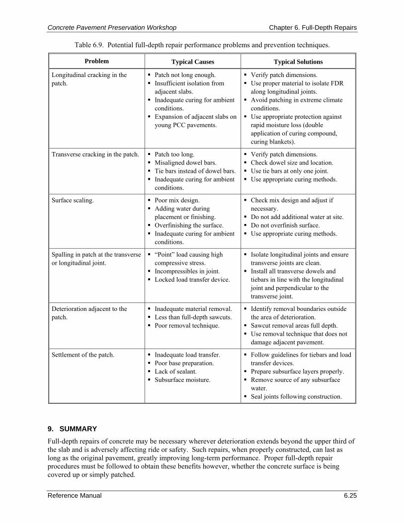
Concrete Pavement Preservation Workshop Chapter 6. Full-Depth Repairs
Reference Manual 6.25
Table 6.9. Potential full-depth repair performance problems and prevention techniques.
Problem Typical Causes Typical Solutions
Longitudinal cracking in the patch.
Patch not long enough. Insufficient isolation from
adjacent slabs. Inadequate curing for ambient
conditions. Expansion of adjacent slabs on
young PCC pavements.
Verify patch dimensions. Use proper material to isolate FDR
along longitudinal joints. Avoid patching in extreme climate
conditions. Use appropriate protection against
rapid moisture loss (double application of curing compound, curing blankets).
Transverse cracking in the patch.
Patch too long. Misaligned dowel bars. Tie bars instead of dowel bars. Inadequate curing for ambient
conditions.
Verify patch dimensions. Check dowel size and location. Use tie bars at only one joint. Use appropriate curing methods.
Surface scaling.
Poor mix design. Adding water during
placement or finishing. Overfinishing the surface. Inadequate curing for ambient
conditions.
Check mix design and adjust if necessary.
Do not add additional water at site. Do not overfinish surface. Use appropriate curing methods.
Spalling in patch at the transverse or longitudinal joint.
“Point” load causing high compressive stress.
Incompressibles in joint. Locked load transfer device.
Isolate longitudinal joints and ensure transverse joints are clean.
Install all transverse dowels and tiebars in line with the longitudinal joint and perpendicular to the transverse joint.
Deterioration adjacent to the patch.
Inadequate material removal. Less than full-depth sawcuts. Poor removal technique.
Identify removal boundaries outside the area of deterioration.
Sawcut removal areas full depth. Use removal technique that does not
damage adjacent pavement.
Settlement of the patch. Inadequate load transfer. Poor base preparation. Lack of sealant. Subsurface moisture.
Follow guidelines for tiebars and load transfer devices.
Prepare subsurface layers properly. Remove source of any subsurface
water. Seal joints following construction.
9. SUMMARY Full-depth repairs of concrete may be necessary wherever deterioration extends beyond the upper third of the slab and is adversely affecting ride or safety. Such repairs, when properly constructed, can last as long as the original pavement, greatly improving long-term performance. Proper full-depth repair procedures must be followed to obtain these benefits however, whether the concrete surface is being covered up or simply patched.
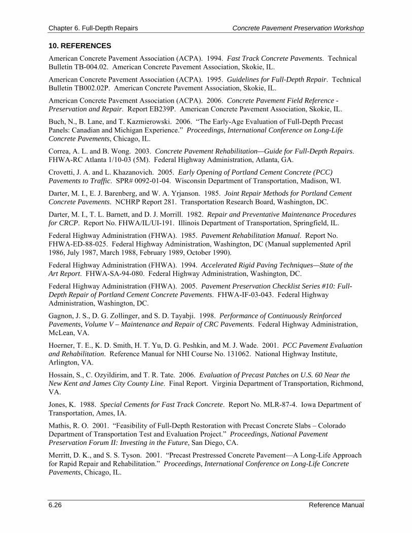
Chapter 6. Full-Depth Repairs Concrete Pavement Preservation Workshop
6.26 Reference Manual
10. REFERENCES American Concrete Pavement Association (ACPA). 1994. Fast Track Concrete Pavements. Technical Bulletin TB-004.02. American Concrete Pavement Association, Skokie, IL.
American Concrete Pavement Association (ACPA). 1995. Guidelines for Full-Depth Repair. Technical Bulletin TB002.02P. American Concrete Pavement Association, Skokie, IL.
American Concrete Pavement Association (ACPA). 2006. Concrete Pavement Field Reference - Preservation and Repair. Report EB239P. American Concrete Pavement Association, Skokie, IL.
Buch, N., B. Lane, and T. Kazmierowski. 2006. “The Early-Age Evaluation of Full-Depth Precast Panels: Canadian and Michigan Experience.” Proceedings, International Conference on Long-Life Concrete Pavements, Chicago, IL.
Correa, A. L. and B. Wong. 2003. Concrete Pavement Rehabilitation—Guide for Full-Depth Repairs. FHWA-RC Atlanta 1/10-03 (5M). Federal Highway Administration, Atlanta, GA.
Crovetti, J. A. and L. Khazanovich. 2005. Early Opening of Portland Cement Concrete (PCC) Pavements to Traffic. SPR# 0092-01-04. Wisconsin Department of Transportation, Madison, WI.
Darter, M. I., E. J. Barenberg, and W. A. Yrjanson. 1985. Joint Repair Methods for Portland Cement Concrete Pavements. NCHRP Report 281. Transportation Research Board, Washington, DC.
Darter, M. I., T. L. Barnett, and D. J. Morrill. 1982. Repair and Preventative Maintenance Procedures for CRCP. Report No. FHWA/IL/UI-191. Illinois Department of Transportation, Springfield, IL.
Federal Highway Administration (FHWA). 1985. Pavement Rehabilitation Manual. Report No. FHWA-ED-88-025. Federal Highway Administration, Washington, DC (Manual supplemented April 1986, July 1987, March 1988, February 1989, October 1990).
Federal Highway Administration (FHWA). 1994. Accelerated Rigid Paving Techniques—State of the Art Report. FHWA-SA-94-080. Federal Highway Administration, Washington, DC.
Federal Highway Administration (FHWA). 2005. Pavement Preservation Checklist Series #10: Full-Depth Repair of Portland Cement Concrete Pavements. FHWA-IF-03-043. Federal Highway Administration, Washington, DC.
Gagnon, J. S., D. G. Zollinger, and S. D. Tayabji. 1998. Performance of Continuously Reinforced Pavements, Volume V – Maintenance and Repair of CRC Pavements. Federal Highway Administration, McLean, VA.
Hoerner, T. E., K. D. Smith, H. T. Yu, D. G. Peshkin, and M. J. Wade. 2001. PCC Pavement Evaluation and Rehabilitation. Reference Manual for NHI Course No. 131062. National Highway Institute, Arlington, VA.
Hossain, S., C. Ozyildirim, and T. R. Tate. 2006. Evaluation of Precast Patches on U.S. 60 Near the New Kent and James City County Line. Final Report. Virginia Department of Transportation, Richmond, VA.
Jones, K. 1988. Special Cements for Fast Track Concrete. Report No. MLR-87-4. Iowa Department of Transportation, Ames, IA.
Mathis, R. O. 2001. “Feasibility of Full-Depth Restoration with Precast Concrete Slabs – Colorado Department of Transportation Test and Evaluation Project.” Proceedings, National Pavement Preservation Forum II: Investing in the Future, San Diego, CA.
Merritt, D. K., and S. S. Tyson. 2001. “Precast Prestressed Concrete Pavement—A Long-Life Approach for Rapid Repair and Rehabilitation.” Proceedings, International Conference on Long-Life Concrete Pavements, Chicago, IL.
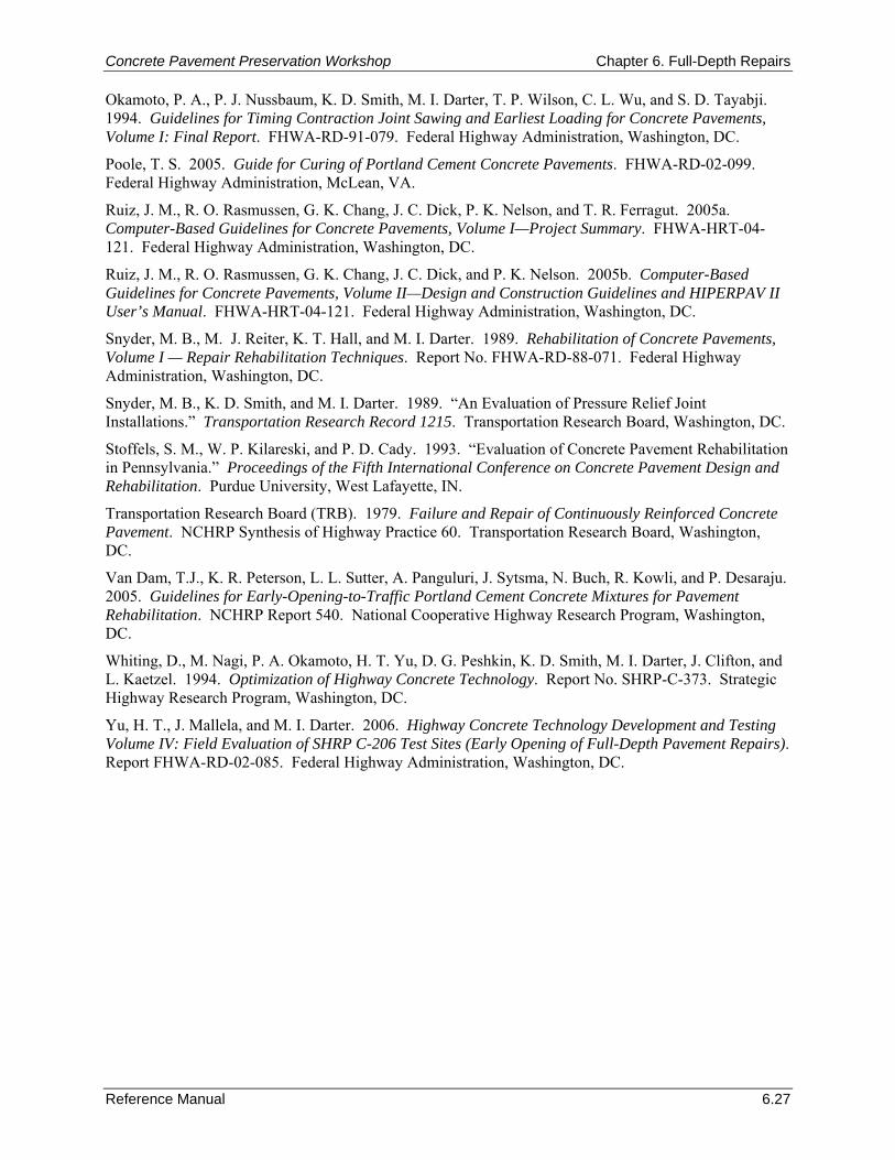
Concrete Pavement Preservation Workshop Chapter 6. Full-Depth Repairs
Reference Manual 6.27
Okamoto, P. A., P. J. Nussbaum, K. D. Smith, M. I. Darter, T. P. Wilson, C. L. Wu, and S. D. Tayabji. 1994. Guidelines for Timing Contraction Joint Sawing and Earliest Loading for Concrete Pavements, Volume I: Final Report. FHWA-RD-91-079. Federal Highway Administration, Washington, DC.
Poole, T. S. 2005. Guide for Curing of Portland Cement Concrete Pavements. FHWA-RD-02-099. Federal Highway Administration, McLean, VA.
Ruiz, J. M., R. O. Rasmussen, G. K. Chang, J. C. Dick, P. K. Nelson, and T. R. Ferragut. 2005a. Computer-Based Guidelines for Concrete Pavements, Volume I—Project Summary. FHWA-HRT-04-121. Federal Highway Administration, Washington, DC.
Ruiz, J. M., R. O. Rasmussen, G. K. Chang, J. C. Dick, and P. K. Nelson. 2005b. Computer-Based Guidelines for Concrete Pavements, Volume II—Design and Construction Guidelines and HIPERPAV II User’s Manual. FHWA-HRT-04-121. Federal Highway Administration, Washington, DC.
Snyder, M. B., M. J. Reiter, K. T. Hall, and M. I. Darter. 1989. Rehabilitation of Concrete Pavements, Volume I — Repair Rehabilitation Techniques. Report No. FHWA-RD-88-071. Federal Highway Administration, Washington, DC.
Snyder, M. B., K. D. Smith, and M. I. Darter. 1989. “An Evaluation of Pressure Relief Joint Installations.” Transportation Research Record 1215. Transportation Research Board, Washington, DC.
Stoffels, S. M., W. P. Kilareski, and P. D. Cady. 1993. “Evaluation of Concrete Pavement Rehabilitation in Pennsylvania.” Proceedings of the Fifth International Conference on Concrete Pavement Design and Rehabilitation. Purdue University, West Lafayette, IN.
Transportation Research Board (TRB). 1979. Failure and Repair of Continuously Reinforced Concrete Pavement. NCHRP Synthesis of Highway Practice 60. Transportation Research Board, Washington, DC.
Van Dam, T.J., K. R. Peterson, L. L. Sutter, A. Panguluri, J. Sytsma, N. Buch, R. Kowli, and P. Desaraju. 2005. Guidelines for Early-Opening-to-Traffic Portland Cement Concrete Mixtures for Pavement Rehabilitation. NCHRP Report 540. National Cooperative Highway Research Program, Washington, DC.
Whiting, D., M. Nagi, P. A. Okamoto, H. T. Yu, D. G. Peshkin, K. D. Smith, M. I. Darter, J. Clifton, and L. Kaetzel. 1994. Optimization of Highway Concrete Technology. Report No. SHRP-C-373. Strategic Highway Research Program, Washington, DC.
Yu, H. T., J. Mallela, and M. I. Darter. 2006. Highway Concrete Technology Development and Testing Volume IV: Field Evaluation of SHRP C-206 Test Sites (Early Opening of Full-Depth Pavement Repairs). Report FHWA-RD-02-085. Federal Highway Administration, Washington, DC.

Chapter 6. Full-Depth Repairs Concrete Pavement Preservation Workshop
6.28 Reference Manual
NOTES
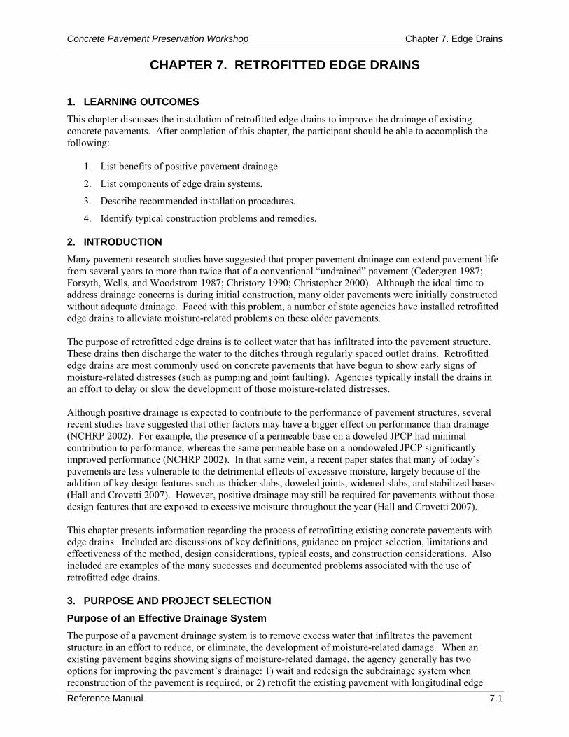
Concrete Pavement Preservation Workshop Chapter 7. Edge Drains
Reference Manual 7.1
CHAPTER 7. RETROFITTED EDGE DRAINS 1. LEARNING OUTCOMES This chapter discusses the installation of retrofitted edge drains to improve the drainage of existing concrete pavements. After completion of this chapter, the participant should be able to accomplish the following:
1. List benefits of positive pavement drainage.
2. List components of edge drain systems.
3. Describe recommended installation procedures.
4. Identify typical construction problems and remedies. 2. INTRODUCTION Many pavement research studies have suggested that proper pavement drainage can extend pavement life from several years to more than twice that of a conventional “undrained” pavement (Cedergren 1987; Forsyth, Wells, and Woodstrom 1987; Christory 1990; Christopher 2000). Although the ideal time to address drainage concerns is during initial construction, many older pavements were initially constructed without adequate drainage. Faced with this problem, a number of state agencies have installed retrofitted edge drains to alleviate moisture-related problems on these older pavements. The purpose of retrofitted edge drains is to collect water that has infiltrated into the pavement structure. These drains then discharge the water to the ditches through regularly spaced outlet drains. Retrofitted edge drains are most commonly used on concrete pavements that have begun to show early signs of moisture-related distresses (such as pumping and joint faulting). Agencies typically install the drains in an effort to delay or slow the development of those moisture-related distresses. Although positive drainage is expected to contribute to the performance of pavement structures, several recent studies have suggested that other factors may have a bigger effect on performance than drainage (NCHRP 2002). For example, the presence of a permeable base on a doweled JPCP had minimal contribution to performance, whereas the same permeable base on a nondoweled JPCP significantly improved performance (NCHRP 2002). In that same vein, a recent paper states that many of today’s pavements are less vulnerable to the detrimental effects of excessive moisture, largely because of the addition of key design features such as thicker slabs, doweled joints, widened slabs, and stabilized bases (Hall and Crovetti 2007). However, positive drainage may still be required for pavements without those design features that are exposed to excessive moisture throughout the year (Hall and Crovetti 2007). This chapter presents information regarding the process of retrofitting existing concrete pavements with edge drains. Included are discussions of key definitions, guidance on project selection, limitations and effectiveness of the method, design considerations, typical costs, and construction considerations. Also included are examples of the many successes and documented problems associated with the use of retrofitted edge drains. 3. PURPOSE AND PROJECT SELECTION Purpose of an Effective Drainage System The purpose of a pavement drainage system is to remove excess water that infiltrates the pavement structure in an effort to reduce, or eliminate, the development of moisture-related damage. When an existing pavement begins showing signs of moisture-related damage, the agency generally has two options for improving the pavement’s drainage: 1) wait and redesign the subdrainage system when reconstruction of the pavement is required, or 2) retrofit the existing pavement with longitudinal edge
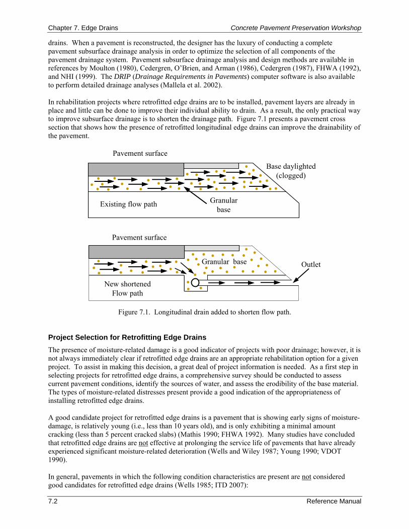
Chapter 7. Edge Drains Concrete Pavement Preservation Workshop
7.2 Reference Manual
drains. When a pavement is reconstructed, the designer has the luxury of conducting a complete pavement subsurface drainage analysis in order to optimize the selection of all components of the pavement drainage system. Pavement subsurface drainage analysis and design methods are available in references by Moulton (1980), Cedergren, O’Brien, and Arman (1986), Cedergren (1987), FHWA (1992), and NHI (1999). The DRIP (Drainage Requirements in Pavements) computer software is also available to perform detailed drainage analyses (Mallela et al. 2002). In rehabilitation projects where retrofitted edge drains are to be installed, pavement layers are already in place and little can be done to improve their individual ability to drain. As a result, the only practical way to improve subsurface drainage is to shorten the drainage path. Figure 7.1 presents a pavement cross section that shows how the presence of retrofitted longitudinal edge drains can improve the drainability of the pavement.
Base daylighted(clogged)
Pavement surface
Existing flow path
Pavement surface
New shortenedFlow path
Granular base
Granularbase
Outlet
Figure 7.1. Longitudinal drain added to shorten flow path. Project Selection for Retrofitting Edge Drains The presence of moisture-related damage is a good indicator of projects with poor drainage; however, it is not always immediately clear if retrofitted edge drains are an appropriate rehabilitation option for a given project. To assist in making this decision, a great deal of project information is needed. As a first step in selecting projects for retrofitted edge drains, a comprehensive survey should be conducted to assess current pavement conditions, identify the sources of water, and assess the erodibility of the base material. The types of moisture-related distresses present provide a good indication of the appropriateness of installing retrofitted edge drains. A good candidate project for retrofitted edge drains is a pavement that is showing early signs of moisture-damage, is relatively young (i.e., less than 10 years old), and is only exhibiting a minimal amount cracking (less than 5 percent cracked slabs) (Mathis 1990; FHWA 1992). Many studies have concluded that retrofitted edge drains are not effective at prolonging the service life of pavements that have already experienced significant moisture-related deterioration (Wells and Wiley 1987; Young 1990; VDOT 1990). In general, pavements in which the following condition characteristics are present are not considered good candidates for retrofitted edge drains (Wells 1985; ITD 2007):
Concrete Pavement Preservation Workshop Chapter 7. Edge Drains
Reference Manual 7.3
More than 10 percent of the surface exhibits cracking.
A high number of transverse joints are spalled.
Where pumping has occurred (unless the voids under the pavement are to be corrected).
Localized distress exists such as edge punchouts, transverse cracking, longitudinal and diagonal cracking, all of which require extensive patching to return the pavement to an adequate level of service.
A cement-treated base exists that is no longer intact.
Pavements where the existing base contains greater than 15 percent fines (material passing the 0.075-mm [No. 200] sieve). Base materials with these characteristics may be too impermeable for an effective retrofitted subdrainage installation (FHWA 1990).
In addition to condition considerations, an ideal candidate for retrofitted edge drains is a project that has acceptable geometrics (longitudinal and transverse slopes) and adequate depth and condition of roadside ditches. It is important that these pavement characteristics be adequate (or improved during edge drain installation) so that water can effectively be removed. 4. LIMITATIONS AND EFFECTIVENESS The performance of pavements with retrofitted edge drains has been mixed. In many instances, the retrofitted edge drains have been effective in removing water from the pavement structure (especially water entering through the lane-shoulder joint), which reduced the development of moisture-related distresses. However, in other instances, retrofitted edge drains have been found to be ineffective in addressing drainage problems, or in some cases have even contributed to the further deterioration of the pavement structure (Gulden 1983; Wells and Nokes 1993). This inconsistent performance has been mostly attributed to a combination of improper usage (project selection), improper design, damage during installation, lack of post-installation maintenance, or the failure to provide other pavement repairs that are needed at the time of retrofitting edge drains. Over the years, a number of national and state studies have focused on assessing the limitations and effectiveness of retrofitted edge drain installations. The results of some of these studies, as well as a summary of SHA experience, are presented in the remainder of this section. Research Study Results A number of research studies have documented both the successes and problems that agencies have had with retrofitting edge drains in existing concrete pavements. A summary of notable research on retrofitted drainage (presented in chronological order) is provided below.
One nationwide study of concrete pavement performance showed that edge drains are highly effective in reducing pumping and faulting in jointed concrete pavements (Darter et al. 1985). The study also showed that edge drains are effective in reducing joint deterioration in D-cracked pavements.
A study by Bradley et al. (1986) examined the performance of concrete pavements with and without longitudinal edge drains in Arkansas, Florida, Louisiana, and New Mexico. The study concluded that edge drains can be effective at extending pavement life.
A 1986 study by the Permanent International Association of Road Congresses (PIARC) investigated the effectiveness of edge drains in reducing pumping when combined with nonerodible materials (PIARC 1986). That study indicated that care must be taken to ensure that the drains are needed, are adequately designed, and are properly installed in a pavement if the pavement's performance is to be improved. A 1998 study emphasized this latter point by
Chapter 7. Edge Drains Concrete Pavement Preservation Workshop
7.4 Reference Manual
concluding that many failures of pavements with subsurface drainage can be attributed to poor design and construction practices (Daleiden 1998).
FHWA Experimental Project 12, Concrete Pavement Drainage Rehabilitation, evaluated the performance of edge drains in 10 States (Baumgardner and Mathis 1989). This study concluded that most of the water being removed through retrofitted edge drains is the water that is either infiltrating the lane-shoulder joint or draining through the voids and channels that have developed at the slab–base interface. In addition, the results of this study suggested that by the time retrofitted edge drains are typically added much of the damage is already done, and the improved drainage may be of questionable value.
Under an NCHRP study, Koerner et al. (1994) investigated the performance of forty-one geocomposite edge drain installations, of which the performance of ten was found to be unacceptable. This contrasted with the performance of other types of edge drains that were deemed “very acceptable.” The failure to place the geocomposite edge drain against the base layer was cited as the primary cause of failure, resulting in soil retention and clogging.
A study by Daleiden (1998) conducted video inspections of in-service edge drains to assess their performance, and revealed that only 30 percent of the in-service edge drains were fully functional. The common causes for poor performance of retrofitted pipe edge drains were discovered to be improper installation, pipe clogging due to fines, and pipe crushing. The common causes of poor performance of geocomposite edge drains were found to be drain damage due to improper installation (crushed or buckled geocomposite panels) and clogging due to caking of fines on the geotextile material.
A 1998 published report discussed the results of a Wisconsin study that focused on evaluating the use of positive drainage systems in pavement structures (Rutkowski, Shober, and Schmeidlin 1998). As part of this study, three different test sections were used to compare the performance of different types of retrofitted edge drains with control sections without positive drainage systems. In all three cases, the performance of the control sections with edge drains was not found to be significantly better than the performance of the sections with retrofitted edge drains. Also, the researchers concluded that the retrofitting of edge drains was not effective in preventing or reducing the progression of faulting.
In a study of the performance of diamond ground pavement sections, time-series performance data for pavements with and without retrofitted edge drains were examined (Rao et al. 1999). It was found that the sections with edge drains were faulted about the same as the nondrained ground sections. It was further determined that the edge drains were ineffective due to clogging (Rao et al. 1999).
The conclusions of a recent NCHRP synthesis study found a general good performance of geocomposite edge drains, and reported that most failures were predictable and related to either a poor drainage design, a misapplication of the treatment, or improper construction techniques (Christopher 2000).
A national study of pavement drainage showed mixed results in terms of the benefits of retrofitted drainage on pavement performance (NCHRP 2002). In some cases, the addition of retrofitted edge drains reduced the rate of faulting development, whereas in other cases there was no such reduction (NCHRP 2002).
Agency Experience with Retrofitted Edge Drains Several agencies have significant experience with the installation of retrofitted edge drains. The following sections summarize some of the more notable agency experiences.
Concrete Pavement Preservation Workshop Chapter 7. Edge Drains
Reference Manual 7.5
In 1981, the State of California began a research project to determine if edge drains were effective at providing rapid drainage, and therefore, minimizing pumping and faulting on their nondoweled JPCP. The results of this research showed that edge drains were indeed effective at reducing the faulting in JPCP by 88 percent (Wells 1985). An additional 5 to 10 years of additional service life was attributed to the installation of retrofitted edge drains.
In the mid 1970s, Georgia installed retrofitted pipe edge drains on several heavily trafficked nondoweled JPC pavements that were experiencing pumping and joint faulting. These pavements had granular bases with high fine contents. Although the retrofitted edge drains reduced the visible signs of pumping, the magnitude of joint faulting and number of cracked slabs continued to increase. An investigation into this poor performance found that significant amounts of fines from the base and subgrade were being transported out of the pavement structure via the edge drain system (Gulden 1983).
Based on an evaluation of the performance of its edge drain installations (both initially installed and retrofitted), Indiana placed a moratorium on the use of geocomposite edge drains in September 1995 (Hassan et al. 1996). Reasons for the moratorium include a concern over the potential clogging of these drains, as well as their susceptibility to damage during installation (Andrewski 1995; Christopher 2000).
Kentucky has been installing longitudinal edge drains on concrete pavements for over 25 years, mostly on the Interstate and parkway systems (Allen 1990). Since 1984, Kentucky has almost exclusively been using geocomposite edge drains. In direct comparisons of geocomposite and pipe edge drains, they report a number of interesting findings. The geocomposite edge drains were found to start draining much more rapidly than pipe edge drains after a rainfall event—a few minutes compared to 24 to 48 hours. However, in studies done by both excavation and bore scope, it was found that some damage (crushing and buckling of the geocomposite edge drain core) to the geocomposite drains had occurred as a result of excessive compactive forces during backfill operations (Fleckenstein and Allen 2000).
In 1997, Kentucky completed an in-depth research study of the performance and construction of their highway edge drain systems. After this study was completed, the Kentucky Department of Highways (DOH) began requiring that all new edge drain installations be inspected with video cameras as part of an initial quality control program. As a result of the camera inspections, the number of edge drain outlet failures decreased from 20 percent to approximately 2 percent by the year 2000 (Fleckenstein and Allen 2000).
A number of State highway agencies have recently documented problems with their use of geocomposite edge drains. Similar to Indiana, Pennsylvania has reported problems including clogging due to siltation and crushing of the drain during installation (Christopher 2000). Illinois discontinued the use of geocomposite edge drains after the results of an extensive evaluation of drainage design policies found numerous examples of improper design, construction, and maintenance (DuBose 1995). Michigan and Wisconsin have also reportedly discontinued the use of geocomposite edge drains due to problems resulting in decreased service life and high initial costs. Although Ohio reported some construction problems, they still found that their geocomposite edge drains were working as a secondary drainage system (Christopher 2000).
In 1997, the Maine Department of Transportation installed a retrofitted edge drain on a section of highway composite pavement near New Gloucester, Maine. A survey of the experimental sections after being in-service for 5 years found that while the sections with retrofitted edge drains showed significantly less load-related cracking and reflection cracking than the control sections, the same sections exhibited more edge cracking (MDOT 2003) It was believed that the edge cracking was attributed to settlement of the experimental drainage systems (MDOT 2003).
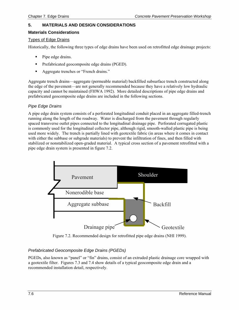
Chapter 7. Edge Drains Concrete Pavement Preservation Workshop
7.6 Reference Manual
5. MATERIALS AND DESIGN CONSIDERATIONS Materials Considerations Types of Edge Drains
Historically, the following three types of edge drains have been used on retrofitted edge drainage projects:
Pipe edge drains.
Prefabricated geocomposite edge drains (PGED).
Aggregate trenches or “French drains.” Aggregate trench drains—aggregate (permeable material) backfilled subsurface trench constructed along the edge of the pavement—are not generally recommended because they have a relatively low hydraulic capacity and cannot be maintained (FHWA 1992). More detailed descriptions of pipe edge drains and prefabricated geocomposite edge drains are included in the following sections. Pipe Edge Drains
A pipe edge drain system consists of a perforated longitudinal conduit placed in an aggregate filled-trench running along the length of the roadway. Water is discharged from the pavement through regularly spaced transverse outlet pipes connected to the longitudinal drainage pipe. Perforated corrugated plastic is commonly used for the longitudinal collector pipe, although rigid, smooth-walled plastic pipe is being used more widely. The trench is partially lined with geotextile fabric (in areas where it comes in contact with either the subbase or subgrade materials) to prevent the infiltration of fines, and then filled with stabilized or nonstabilized open-graded material. A typical cross section of a pavement retrofitted with a pipe edge drain system is presented in figure 7.2.
GeotextileDrainage pipe
ShoulderPavement
Nonerodible base
Aggregate subbase Backfill
Figure 7.2. Recommended design for retrofitted pipe edge drains (NHI 1999).
Prefabricated Geocomposite Edge Drains (PGEDs)
PGEDs, also known as “panel” or “fin” drains, consist of an extruded plastic drainage core wrapped with a geotextile filter. Figures 7.3 and 7.4 show details of a typical geocomposite edge drain and a recommended installation detail, respectively.
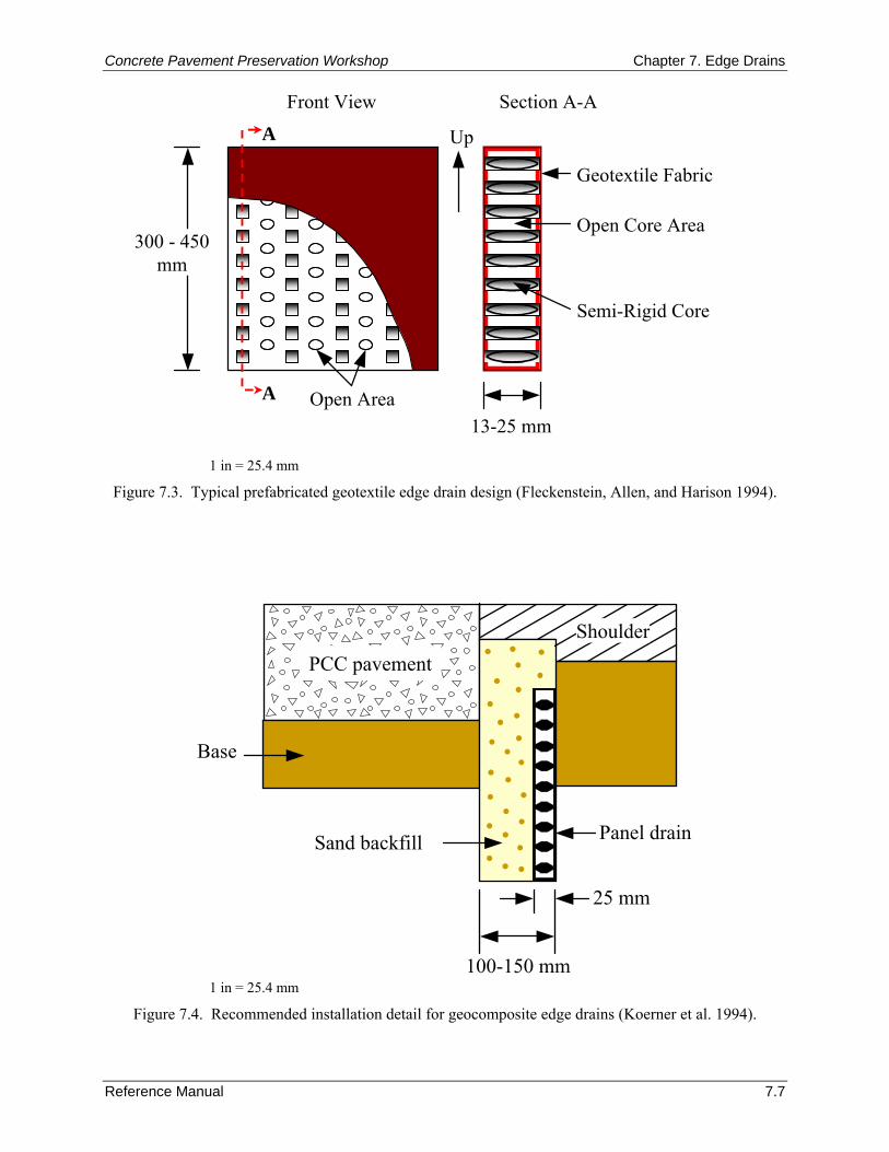
Concrete Pavement Preservation Workshop Chapter 7. Edge Drains
Reference Manual 7.7
Front View
A
A Up
Section A-A
300 - 450 mm
Open Core Area
Geotextile Fabric
Semi-Rigid Core
Open Area13-25 mm
1 in = 25.4 mm
Figure 7.3. Typical prefabricated geotextile edge drain design (Fleckenstein, Allen, and Harison 1994).
100-150 mm
Panel drainSand backfill
Base
25 mm
PCC pavementShoulder
1 in = 25.4 mm
Figure 7.4. Recommended installation detail for geocomposite edge drains (Koerner et al. 1994).

Chapter 7. Edge Drains Concrete Pavement Preservation Workshop
7.8 Reference Manual
Geocomposite edge drains are typically 13 to 25 mm (0.5 to 1 in) thick and are manufactured in long strips that are coiled into rolls. Their size and the incorporation of a geotextile filter in their design means that they can be placed in narrower trenches (as compared to conventional pipe edge drain installations). In some of the early projects, the trenched soil was also used to backfill the trench. Many incidents of drain clogging (infiltration of fine material) have been attributed to this practice. An evaluation of the field performance of geocomposite edge drains found the infiltration of fines into the drain to be the most common problem with this type of edge drain (Koerner et al. 1994). These problems are believed to be adequately addressed through modifications to the backfill material (i.e., requiring a good quality granular backfill/filter material) and careful placement of the geocomposite edge drain. Although geocomposite edge drains generally have less drainage capacity than pipe edge drains, this is not typically a problem on most retrofitted drainage projects. The reason for this is that the majority of pavements identified as good candidates for retrofitted edge drains are those that were originally constructed with poorly draining bases and subbases. However, due to these recognized capacity limits, geocomposite edge drains should be used with caution on rehabilitation projects where high water inflows are expected (e.g., HMA overlays on cracked and seated or rubblized concrete pavements). Newer geocomposite material products are now being developed with higher hydraulic capacities for use on these types of projects. The two main advantages of geocomposite edge drains over traditional pipe edge drains are 1) they are easier to install, and 2) they are substantially cheaper in cost. One disadvantage of geocomposite edge drains is their susceptibility to damage during construction. If proper care is not taken during backfilling operations, crushing, bending, or buckling of the drainage core may occur (Koerner et al. 1994). However, past research studies have indicated that drain clogging can be minimized by using the installation detail shown in figure 7.4, and that damage from backfilling can be avoided by compacting the sand backfill using water puddling (Fleckenstein, Allen, and Harison 1994; Koerner et al. 1994). Overall, many studies have concluded that geocomposite edge drains can function as well as pipe edge drains as long as they are properly installed (Mathis 1990; Koerner et al. 1994). Backfill Material
The backfill/filler material placed in the trench around the pipe or alongside the geocomposite serves the following functions:
It acts as a drainage medium to provide a means by which water is moved from the pavement layers to the drainage pipe.
It acts a filter system that prevents fines from moving into and clogging the drainage system.
It supports and confines the drain pipe or geocomposite, providing protection both during construction and while in service.
It provides stabilization to the soil around the drainage trench. There are specific procedures available for designing the backfill/filler material to ensure that the drainage feature, be it a pipe or geocomposite, does not become clogged with fines. Recommended gradations are included in the Highway Subdrainage Design manual (Moulton 1980). For pipe edge drains, the backfill material for the trench should be at least as permeable as the base material. In a permeable base section, the backfill material will usually be the same as the base material. AASHTO No. 57 gradation should provide sufficient permeability and stability for use as nonstabilized backfill material. Nonstabilized pea gravels are not recommended as the backfill material because they cannot be compacted satisfactorily (Wells 1990). Proper compaction of the backfill material is important to avoid settlement over the edge drain.
Concrete Pavement Preservation Workshop Chapter 7. Edge Drains
Reference Manual 7.9
Design Considerations The design of edge drains is a multi-step process that mainly consists of calculating the amount of water that is expected to infiltrate a pavement, and then selecting edge drain details that allow the drainage system to effectively remove the water from the pavement. In addition to sizing the components of the drainage system, it is important to design filters (geotextile or aggregate) that are effective at preventing fines from entering the edge drain (not clogging) over the life of the system (Christopher 2000). The grade of the invert must also be established to maintain flow and the outlets must be spaced and sized appropriately to prevent backup in the edge drain system (Christopher 2000). Details for designing edge drains for new construction or major reconstruction projects are presented by Moulton (1980) and FHWA (1992). A computer program, DRIP (Drainage Requirements in Pavements), is also available for conducting the detailed drainage analyses (Mallela et al. 2002). This section provides an abbreviated explanation of the major considerations associated with designing effective retrofitted edge drains, with more detailed information provided elsewhere (Moulton 1980; FHWA 1992; NHI 1999). Estimate Design Flow Rate
The first step in the design of retrofitted edge drains is the determination of the net inflow of water. The subdrainage system must be adequately sized to handle the flow of water to which it will be subjected. As previously mentioned, for rehabilitation projects, surface infiltration is of primary concern. Groundwater, meltwater, and subgrade outflow are generally relatively small and often ignored in the analysis. The infiltration of water through cracks, joints, and voids in the pavement surface is a major source of water that must always be included in estimating the net inflow. The amount of infiltration is a function of not only pavement cracking and surface permeability, but also of the ability of the base course to accept and remove water. Consequently, the actual infiltration will be the lesser of two values: the amount of water that could enter through cracks, joints, and so on, or the amount of water that the base course is able to accept. The design flow rate is an estimate of the amount of infiltrated water that will be required to be discharged through the edge drain system (in units of volume per time). This value is typically estimated by knowing detailed information about the base (e.g., width, thickness, permeability) and encountered slopes (cross-slope and longitudinal edge drain slope). Details of the available methods for computing this design flow rate are described in the NHI Reference Manual on subsurface drainage (NHI 1999). Edge Drain (Collector) Type
As mentioned previously, two types of longitudinal edge drains are commonly used for retrofitted drainage projects: pipe edge drains and prefabricated geocomposite edge drains. It is important that the selected collector type be compatible with the existing pavement structure, as well as the surrounding materials. For pipe edge drains, several types of drainage pipe of various lengths and diameters have been used successfully in collector systems. Highway agencies use flexible, corrugated polyethylene (CPE) or smooth rigid polyvinyl chloride (PVC) pipe, adhering to AASHTO M 252 or AASHTO M 278 Class 50, respectively. For geocomposite edge drains, product selection should consider an evaluation based on the test procedures outlined in ASTM D 6244-98, Test Method for Vertical Compression of Geocomposite Pavement Panel Drains (Christopher 2000).
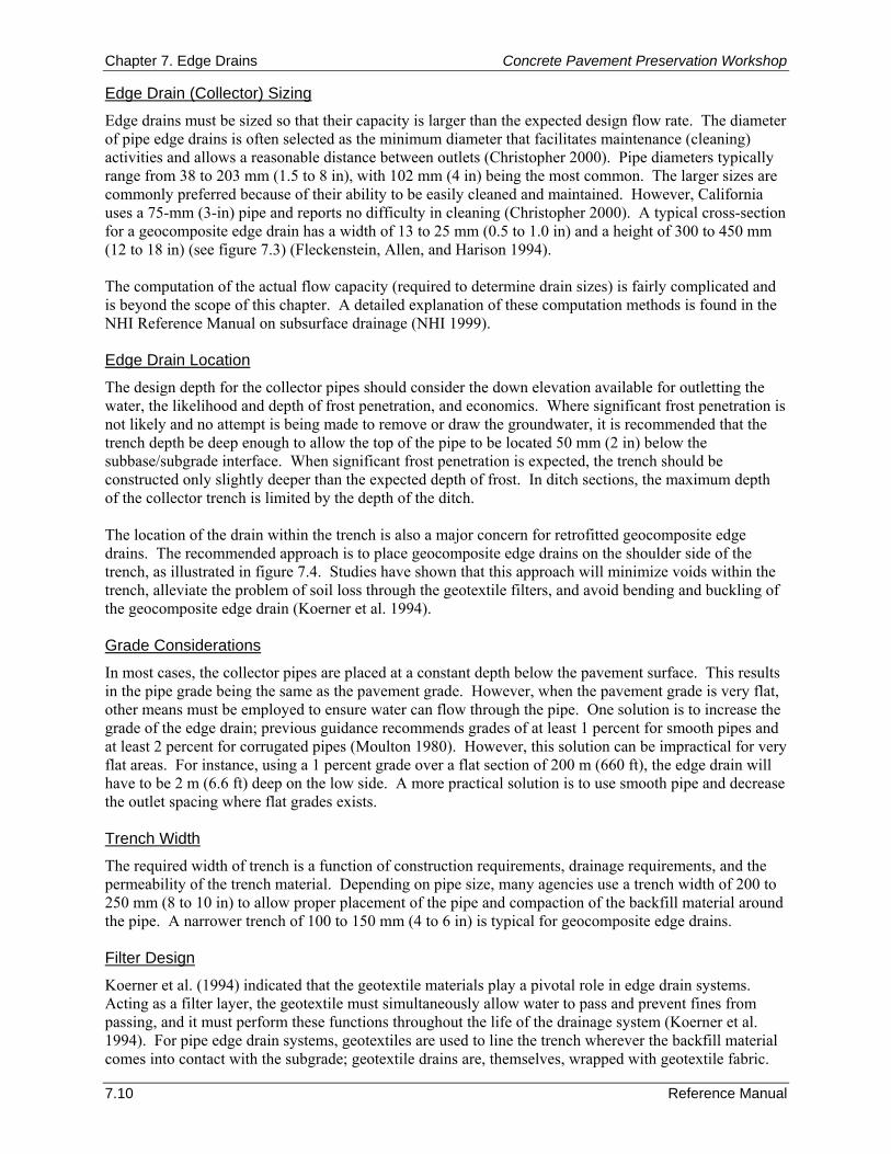
Chapter 7. Edge Drains Concrete Pavement Preservation Workshop
7.10 Reference Manual
Edge Drain (Collector) Sizing
Edge drains must be sized so that their capacity is larger than the expected design flow rate. The diameter of pipe edge drains is often selected as the minimum diameter that facilitates maintenance (cleaning) activities and allows a reasonable distance between outlets (Christopher 2000). Pipe diameters typically range from 38 to 203 mm (1.5 to 8 in), with 102 mm (4 in) being the most common. The larger sizes are commonly preferred because of their ability to be easily cleaned and maintained. However, California uses a 75-mm (3-in) pipe and reports no difficulty in cleaning (Christopher 2000). A typical cross-section for a geocomposite edge drain has a width of 13 to 25 mm (0.5 to 1.0 in) and a height of 300 to 450 mm (12 to 18 in) (see figure 7.3) (Fleckenstein, Allen, and Harison 1994). The computation of the actual flow capacity (required to determine drain sizes) is fairly complicated and is beyond the scope of this chapter. A detailed explanation of these computation methods is found in the NHI Reference Manual on subsurface drainage (NHI 1999). Edge Drain Location
The design depth for the collector pipes should consider the down elevation available for outletting the water, the likelihood and depth of frost penetration, and economics. Where significant frost penetration is not likely and no attempt is being made to remove or draw the groundwater, it is recommended that the trench depth be deep enough to allow the top of the pipe to be located 50 mm (2 in) below the subbase/subgrade interface. When significant frost penetration is expected, the trench should be constructed only slightly deeper than the expected depth of frost. In ditch sections, the maximum depth of the collector trench is limited by the depth of the ditch. The location of the drain within the trench is also a major concern for retrofitted geocomposite edge drains. The recommended approach is to place geocomposite edge drains on the shoulder side of the trench, as illustrated in figure 7.4. Studies have shown that this approach will minimize voids within the trench, alleviate the problem of soil loss through the geotextile filters, and avoid bending and buckling of the geocomposite edge drain (Koerner et al. 1994). Grade Considerations
In most cases, the collector pipes are placed at a constant depth below the pavement surface. This results in the pipe grade being the same as the pavement grade. However, when the pavement grade is very flat, other means must be employed to ensure water can flow through the pipe. One solution is to increase the grade of the edge drain; previous guidance recommends grades of at least 1 percent for smooth pipes and at least 2 percent for corrugated pipes (Moulton 1980). However, this solution can be impractical for very flat areas. For instance, using a 1 percent grade over a flat section of 200 m (660 ft), the edge drain will have to be 2 m (6.6 ft) deep on the low side. A more practical solution is to use smooth pipe and decrease the outlet spacing where flat grades exists. Trench Width
The required width of trench is a function of construction requirements, drainage requirements, and the permeability of the trench material. Depending on pipe size, many agencies use a trench width of 200 to 250 mm (8 to 10 in) to allow proper placement of the pipe and compaction of the backfill material around the pipe. A narrower trench of 100 to 150 mm (4 to 6 in) is typical for geocomposite edge drains. Filter Design
Koerner et al. (1994) indicated that the geotextile materials play a pivotal role in edge drain systems. Acting as a filter layer, the geotextile must simultaneously allow water to pass and prevent fines from passing, and it must perform these functions throughout the life of the drainage system (Koerner et al. 1994). For pipe edge drain systems, geotextiles are used to line the trench wherever the backfill material comes into contact with the subgrade; geotextile drains are, themselves, wrapped with geotextile fabric.
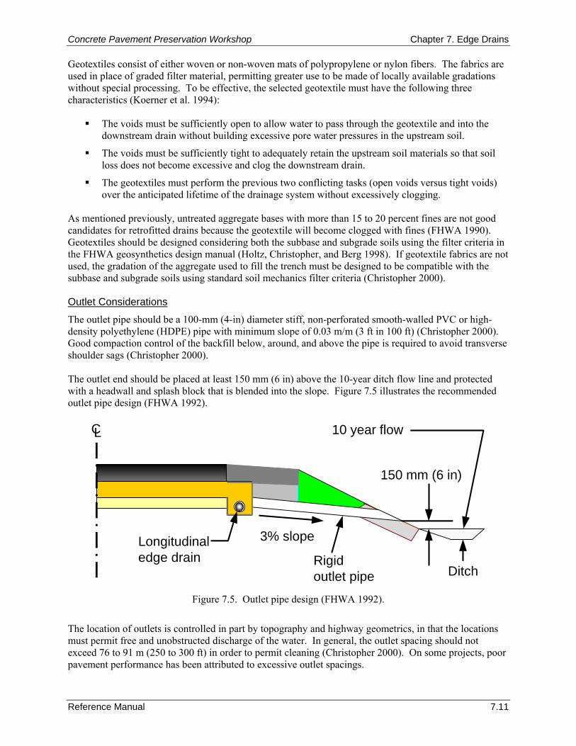
Concrete Pavement Preservation Workshop Chapter 7. Edge Drains
Reference Manual 7.11
Geotextiles consist of either woven or non-woven mats of polypropylene or nylon fibers. The fabrics are used in place of graded filter material, permitting greater use to be made of locally available gradations without special processing. To be effective, the selected geotextile must have the following three characteristics (Koerner et al. 1994):
The voids must be sufficiently open to allow water to pass through the geotextile and into the downstream drain without building excessive pore water pressures in the upstream soil.
The voids must be sufficiently tight to adequately retain the upstream soil materials so that soil loss does not become excessive and clog the downstream drain.
The geotextiles must perform the previous two conflicting tasks (open voids versus tight voids) over the anticipated lifetime of the drainage system without excessively clogging.
As mentioned previously, untreated aggregate bases with more than 15 to 20 percent fines are not good candidates for retrofitted drains because the geotextile will become clogged with fines (FHWA 1990). Geotextiles should be designed considering both the subbase and subgrade soils using the filter criteria in the FHWA geosynthetics design manual (Holtz, Christopher, and Berg 1998). If geotextile fabrics are not used, the gradation of the aggregate used to fill the trench must be designed to be compatible with the subbase and subgrade soils using standard soil mechanics filter criteria (Christopher 2000). Outlet Considerations
The outlet pipe should be a 100-mm (4-in) diameter stiff, non-perforated smooth-walled PVC or high-density polyethylene (HDPE) pipe with minimum slope of 0.03 m/m (3 ft in 100 ft) (Christopher 2000). Good compaction control of the backfill below, around, and above the pipe is required to avoid transverse shoulder sags (Christopher 2000). The outlet end should be placed at least 150 mm (6 in) above the 10-year ditch flow line and protected with a headwall and splash block that is blended into the slope. Figure 7.5 illustrates the recommended outlet pipe design (FHWA 1992).
Rigid outlet pipe
Longitudinaledge drain
CL
3% slope
150 mm (6 in)
Ditch
10 year flow
Figure 7.5. Outlet pipe design (FHWA 1992).
The location of outlets is controlled in part by topography and highway geometrics, in that the locations must permit free and unobstructed discharge of the water. In general, the outlet spacing should not exceed 76 to 91 m (250 to 300 ft) in order to permit cleaning (Christopher 2000). On some projects, poor pavement performance has been attributed to excessive outlet spacings.
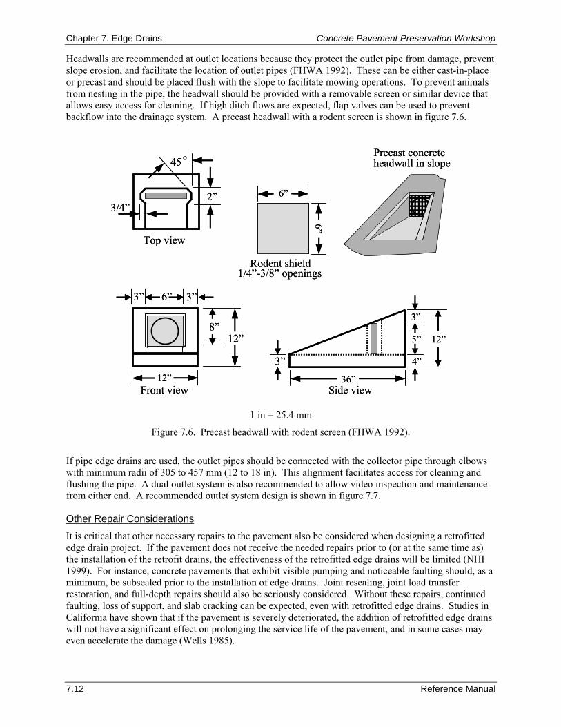
Chapter 7. Edge Drains Concrete Pavement Preservation Workshop
7.12 Reference Manual
Headwalls are recommended at outlet locations because they protect the outlet pipe from damage, prevent slope erosion, and facilitate the location of outlet pipes (FHWA 1992). These can be either cast-in-place or precast and should be placed flush with the slope to facilitate mowing operations. To prevent animals from nesting in the pipe, the headwall should be provided with a removable screen or similar device that allows easy access for cleaning. If high ditch flows are expected, flap valves can be used to prevent backflow into the drainage system. A precast headwall with a rodent screen is shown in figure 7.6.
Precast concreteheadwall in slope
3”36”
4”
3”
5” 12”
12”
12”8”
6”3” 3”
6”
6”
2”
45 o
3/4”
Top view
Front view Side view
Rodent shield1/4”-3/8” openings
Precast concreteheadwall in slope
3”36”
4”
3”
5” 12”
12”
12”8”
6”3” 3”
6”
6”
2”
45 o
3/4”
Top view
Front view Side view
Rodent shield1/4”-3/8” openings
1 in = 25.4 mm
Figure 7.6. Precast headwall with rodent screen (FHWA 1992).
If pipe edge drains are used, the outlet pipes should be connected with the collector pipe through elbows with minimum radii of 305 to 457 mm (12 to 18 in). This alignment facilitates access for cleaning and flushing the pipe. A dual outlet system is also recommended to allow video inspection and maintenance from either end. A recommended outlet system design is shown in figure 7.7. Other Repair Considerations
It is critical that other necessary repairs to the pavement also be considered when designing a retrofitted edge drain project. If the pavement does not receive the needed repairs prior to (or at the same time as) the installation of the retrofit drains, the effectiveness of the retrofitted edge drains will be limited (NHI 1999). For instance, concrete pavements that exhibit visible pumping and noticeable faulting should, as a minimum, be subsealed prior to the installation of edge drains. Joint resealing, joint load transfer restoration, and full-depth repairs should also be seriously considered. Without these repairs, continued faulting, loss of support, and slab cracking can be expected, even with retrofitted edge drains. Studies in California have shown that if the pavement is severely deteriorated, the addition of retrofitted edge drains will not have a significant effect on prolonging the service life of the pavement, and in some cases may even accelerate the damage (Wells 1985).
Concrete Pavement Preservation Workshop Chapter 7. Edge Drains
Reference Manual 7.13
Hose flushing the system
Outlet pipe
Headwall
Collector pipe
300 - 450 mm radius
Hose flushing the system
Outlet pipe
Headwall
Collector pipe
300 - 450 mm radius
1 in = 25.4 mm
Figure 7.7. Recommended outlet detail to facilitate system cleaning and video camera inspections (FHWA 1992).
6. CONSTRUCTION CONSIDERATIONS Proper construction and maintenance are extremely important to ensure effective edge drains. Inconsistent performance of edge drains, resulting from construction or maintenance problems, has hampered the ability to determine the effectiveness of edge drains in improving pavement performance. The construction steps involved in retrofitting edge drains on an existing pavement differ slightly depending on the type of edge drain being used. The differences in construction considerations for pipe edge drains and geocomposite edge drains are presented separately below. Pipe Edge Drains Trenching
It is important to maintain correct line and grade when installing longitudinal underdrains. A mechanical track-driven trencher is often used to create a trench along the edge of the pavement. A large diameter, carbide-tipped wheel saw may also be used. The spoils from the trench must be expelled from the trench and any excess, loose, or foreign material swept away. As described previously, where significant frost penetration is not likely and no attempt is being made to remove or draw the groundwater, it is recommended that the trench depth be deep enough to allow the top of the drain be located 50 mm (2 in) below the subbase/subgrade interface. When significant frost penetration is expected, the trench should be constructed only slightly deeper than the expected depth of frost to ensure that the system can function during freezing periods. In ditch sections, the maximum depth of the collector trench is limited by the depth of the ditch. Outlets from the system should be located 150 mm (6 in) above the ditch flowline to preclude backflow of water from the ditch. Similarly, if the system is to outlet into a storm drain system, the outlet invert should be at least 150 mm (6 in) above the 10-year expected water level in the storm drain system (see figure 7.5). Placement of Geotextile
When pipe edge drains are used, the trench should be lined with a geotextile to prevent migration of fines from the surrounding soil into the drainage trench; however the top of the trench adjacent to the permeable base should be left open to allow a direct path for water into the drainage pipe. The geotextile must satisfy the filter requirements described previously in this chapter.
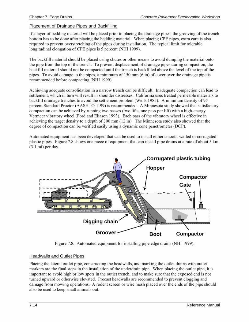
Chapter 7. Edge Drains Concrete Pavement Preservation Workshop
7.14 Reference Manual
Placement of Drainage Pipes and Backfilling
If a layer of bedding material will be placed prior to placing the drainage pipes, the grooving of the trench bottom has to be done after placing the bedding material. When placing CPE pipes, extra care is also required to prevent overstretching of the pipes during installation. The typical limit for tolerable longitudinal elongation of CPE pipes is 5 percent (NHI 1999). The backfill material should be placed using chutes or other means to avoid dumping the material onto the pipe from the top of the trench. To prevent displacement of drainage pipes during compaction, the backfill material should not be compacted until the trench is backfilled above the level of the top of the pipes. To avoid damage to the pipes, a minimum of 150 mm (6 in) of cover over the drainage pipe is recommended before compacting (NHI 1999). Achieving adequate consolidation in a narrow trench can be difficult. Inadequate compaction can lead to settlement, which in turn will result in shoulder distresses. California uses treated permeable materials to backfill drainage trenches to avoid the settlement problem (Wells 1985). A minimum density of 95 percent Standard Proctor (AASHTO T-99) is recommended. A Minnesota study showed that satisfactory compaction can be achieved by running two passes (two lifts, one pass per lift) with a high-energy Vermeer vibratory wheel (Ford and Eliason 1993). Each pass of the vibratory wheel is effective in achieving the target density to a depth of 300 mm (12 in). The Minnesota study also showed that the degree of compaction can be verified easily using a dynamic cone penetrometer (DCP). Automated equipment has been developed that can be used to install either smooth-walled or corrugated plastic pipes. Figure 7.8 shows one piece of equipment that can install pipe drains at a rate of about 5 km (3.1 mi) per day.
Corrugated plastic tubing
Hopper
CompactorGate
CompactorGroover
Digging chain
Boot Figure 7.8. Automated equipment for installing pipe edge drains (NHI 1999).
Headwalls and Outlet Pipes
Placing the lateral outlet pipe, constructing the headwalls, and marking the outlet drains with outlet markers are the final steps in the installation of the underdrain pipe. When placing the outlet pipe, it is important to avoid high or low spots in the outlet trench, and to make sure that the exposed end is not turned upward or otherwise elevated. Precast headwalls are recommended to prevent clogging and damage from mowing operations. A rodent screen or wire mesh placed over the ends of the pipe should also be used to keep small animals out.
Concrete Pavement Preservation Workshop Chapter 7. Edge Drains
Reference Manual 7.15
Geocomposite Edge Drains Trenching
The trench should be cut 100 to 150 mm (4 to 6 in) wide and deep enough to place the top of the panel drain 50 mm (2 in) above the bottom of the pavement surface layer. Typical dimensions for a geocomposite edge drain consist of an inside cross-sectional thickness of 13 to 25 mm (0.5 to 1 in) and a depth of 300 to 450 mm (12 to 18 in). Installation of the Geocomposite Edge Drain
The drain should be placed on the shoulder side of the trench, and the trench should be backfilled with coarse sand to ensure intimate contact between the geotextile and the material being drained. Achieving this contact is very important to prevent loss of fines through the geotextile. Maintaining the verticality of the drain panel in the trench during the backfill operation by utilizing a drain panel-positioning wheel or plate is recommended (Elfino, Riley, and Bass 2000). When required, splices should be made prior to placing the drain in the trench and using the splice kits provided by the manufacturer. The splice should not impede the open flow area of the panel. Vertical and horizontal alignment of the drain should be maintained through the splice, and the splice should not allow infiltration of backfill or any fine material. Headwalls and Outlets
Prior to any backfilling, the geocomposite edge drains should be connected to drainage outlets. As with pipe edge drains, it is recommended that headwalls be used on the outlets to prevent clogging and damage from mowing operations. Finally, all outlet drains should be clearly marked with outlet markers. Backfilling
For geocomposite edge drains, excessive compaction can cause problems. Excessive compactive forces can cause crushing and buckling of the geocomposite edge drain panels. The recommended procedure is to backfill using coarse sand and compact by flushing with water (Koerner et al. 1994). The cuttings from the drainage trench are not a suitable backfill material when installing a geocomposite edge drain. If the panel design is not symmetrical about the vertical axis, the panel should be installed with the rigid or semi-rigid back facing the sand backfill (Fleckenstein, Allen, and Harison 1994). 7. TROUBLESHOOTING Poorly maintained drains can be worse than having no drains at all. It cannot be overemphasized that all subdrainage features, whether installed during initial construction or retrofitted, must be adequately maintained in order to perform properly. Some of the problems that can occur over the life of a drainage system include (Christopher 2000):
Crushed or punctured outlets.
Outlet pipes that are clogged with debris, rodent nests, mowing clippings, vegetation, and sediment.
Edge drains (both pipe drains and fin drains) that are filled with sediment, especially at slopes of less than 1 percent.
Missing rodent screens at outlets.
Missing outlet markers.
Erosion around outlet headwalls.
Shallow ditches that have inadequate slopes and that are clogged with vegetation.
Chapter 7. Edge Drains Concrete Pavement Preservation Workshop
7.16 Reference Manual
Adequate maintenance actually begins in the design stage, when a system is constructed so that it can be adequately maintained. This includes the placement of outlet markers, 610 to 914 mm (24 to 36 in) above the ground and suitably marked, to locate transverse outlets, using concrete headwalls with permanent anti-intrusion protection (screens), and specifying proper connectors to allow periodic flushing or jet rodding of the edge drain system. Permanent markers and concrete headwalls also serve as a reminder of the existence of the system and the need for its maintenance. It is recommended that routine drainage-related maintenance activities be conducted at least twice a year. Examples of some of these maintenance activities include:
Mowing around drainage outlets.
Inspection of the drainage outlets and flushing if necessary.
Removal of vegetation and roadside debris from pipe outlets, daylighted edges, and ditches.
Replacement of missing rodent screens, outlet markers, and eroded headwalls.
Inspection of ditches to ensure that adequate slopes and depths are maintained. Even when all design parameters are properly evaluated and included in the design, the effect of retrofitted subdrainage on pavement performance may not be as expected, and the benefits discussed earlier may not be attainable. An evaluation program that provides feedback data will help the design engineer to determine if there are any aspects of the design that may be detrimental to long-term performance. These programs cannot be short-term evaluations because many moisture-related distresses take time to develop. 8. SUMMARY Pavement engineers are often faced with older concrete pavements that are displaying moisture-related damage, which may be attributed to a combination of inadequate initial drainage design, subsurface drainage system damage, or inadequate drainage system maintenance practices. To address these drainage-related problems, one rehabilitation option is the retrofitting of the existing pavement with edge drains. The historical field performance of retrofitted edge drains has been mixed, ranging from reduced pavement deterioration to a detrimental effect on a few projects. The cases of poor performance have generally been attributed to inappropriate use, improper installation, or lack of maintenance; however, even when the edge drains do drain water, the benefits are difficult to assess. For the time being, local experience may offer the best guidance on whether retrofitted edge drains will be effective. Proper construction and maintenance are extremely important to the long-term effectiveness of edge drains. The installation of retrofitted edge drains should be considered on projects in which all of the following conditions are met:
The primary source of water affecting pavement performance is surface infiltration.
The pavement is less than 15 years old.
The base material is not highly erodible (less than 15 percent material passing 0.075-mm sieve) or dense.
The pavement is in relatively good condition (i.e., there are no signs of severe moisture-damage and the pavement contains less than 5 percent cracked slabs).
Concrete Pavement Preservation Workshop Chapter 7. Edge Drains
Reference Manual 7.17
Both pipe and geocomposite edge drains have been used with success on retrofitted drainage projects. The design and construction details differ slightly between these two drain types. Geocomposite edge drains are less expensive to install but are difficult to maintain (i.e., they are nearly impossible to clean if they become clogged). Typically geocomposite drains have lower hydraulic capacities than pipe drains, although newer materials are changing this trend. Pipe edge drains on the other hand have higher hydraulic capacities but are more expensive. 9. REFERENCES Allen, D. 1990. Kentucky's Experience with Longitudinal Edge Drains. Virginia Pavement Drainage Workshop. Virginia Department of Transportation, Williamsburg, VA.
Andrewski, D. H. 1995. Geocomposite Edge Drains. Memorandum, Indiana Department of Transportation, Pavement Committee. Indiana Department of Transportation, Indianapolis, IN.
Baumgardner, R. H. and D. M. Mathis. 1989. Concrete Pavement Drainage Rehabilitation, State of the Practice Report. Experimental Project No. 12. Federal Highway Administration, Demonstration Projects Division, Washington, DC.
Bradley, M., T. J. Larsen, W. Temple, R. Gains, and A. Thomas. 1986. Longitudinal Edge Drains in Rigid Pavement Systems. Report FHWA-TS-86-208. Federal Highway Administration, Washington, DC.
Cedergren, H. R. 1987. Drainage of Highway and Airfield Pavements. Robert. E. Krieger Publishing Co, Inc., Malabar, FL.
Cedergren, H. R., K. H. O’Brien, and J. A. Arman. 1986. Guidelines for the Design of Subsurface Drainage Systems for Highway Structural Systems. FHWA-TS-86-208. Federal Highway Administration, Washington, DC.
Christopher, B. R. 2000. Maintenance of Highway Edge Drains. NCHRP Synthesis of Highway Practice 285. Transportation Research Board, Washington, DC.
Christory, J. P. 1990. “Assessment of PIARC Recommendations on the Combating of Pumping in Concrete Pavements.” Sixth International Symposium on Concrete Roads. PIARC, Madrid, Spain.
Daleiden, J. F. 1998. Video Inspection of Highway Edge Drain Systems. Report FHWA-SA-98-044. Federal Highway Administration, Washington, DC.
Darter, M. I., J. M. Becker, M. B. Snyder, and R. E. Smith. 1985. Portland Cement Concrete Pavement Evaluation System (COPES). NCHRP Report 277. Transportation Research Board, Washington, DC.
DuBose, J. B. 1995. An Evaluation of IDOT’s Current Underdrain Systems. IL PRR-120. Illinois Department of Transportation, Springfield, IL.
Elfino, M. K., D. G. Riley, and T. R. Baas. 2000. “Key Installation Issues Impacting the Performance of Geocomposite Pavement Edge Drain Systems.” Testing and Performance of Geosynthetics in Subsurface Drainage, ASTM STP 1390. American Society for Testing and Materials, West Conshohocken, PA.
Federal Highway Administration (FHWA). 1990. Technical Guide Paper on Subsurface Pavement Drainage. Technical Paper 90-01. Federal Highway Administration, Washington, DC.
Federal Highway Administration (FHWA). 1992. Drainable Pavement Systems—Participant Notebook. Demonstration Project 87. FHWA-SA-92-008. Federal Highway Administration, Washington, DC.
Fleckenstein, L. J. and D. L. Allen. 2000. “Development of a Performance-Based Specification (QC/QA) for Highway Edge Drains in Kentucky.” Testing and Performance of Geosynthetics in Subsurface Drainage, ASTM STP 1390. American Society for Testing and Materials, West Conshohocken, PA.
Fleckenstein, L. J., D. L. Allen, and J. A. Harison. 1994. Evaluation of Pavement Edge Drains and the Effect on Pavement Performance. Report KTC-94-20. Kentucky Transportation Cabinet, Frankfort, KY.
Chapter 7. Edge Drains Concrete Pavement Preservation Workshop
7.18 Reference Manual
Ford, G. R., and B. E. Eliason. 1993. “Comparison of Compaction Methods in Narrow Subsurface Drainage Trenches.” Transportation Research Record 1425. Transportation Research Board. Washington, DC.
Forsyth, R. A., G. K. Wells, and J. H. Woodstrom. 1987. “The Economic Impact of Pavement Subsurface Drainage.” Transportation Research Record 1121. Transportation Research Board. Washington, DC.
Gulden, W. 1983. “Experience in Georgia with Drainage of Jointed Concrete Pavements.” Proceedings, International Seminar on Drainage and Erodability at the Concrete Slab-Subbase-Shoulder Interface. Permanent International Association of Road Congresses (PIARC), Paris, France.
Hall, K. T. and J. A. Crovetti. 2007. “Performance of Drained and Undrained Rigid Pavements in Long-Term Pavement Performance SPS-2 Experiment.” Preprint Paper 07-3495. 86th Annual Meeting of the Transportation Research Board, Washington, DC.
Hassan, H. F., T. D. White, R. S. McDaniel, D. H. Andrewski. 1996. “Indiana Subdrainage Experience and Application.” Transportation Research Record 1519. Transportation Research Board. Washington, DC.
Holtz, R. D., B. R. Christopher, and R. R. Berg. 1998. Geosynthetic Design and Construction Guidelines (Participant Notebook). FHWA-HI-95-038. National Highway Institute, Arlington, VA.
Idaho Transportation Department (ITD). 2007. Materials Subsurface Pavement Drainage Manual. Section 550.08: Retrofitting Drainage Collection System. Idaho Transportation Department, Boise, ID.
Koerner, R. M., G. R. Koerner, A. K. Fahim, and R. F. Wilson-Fahmy. 1994. Long-Term Performance of Geosynthetics in Drainage Applications. NCHRP Report 367. Transportation Research Board, Washington, DC.
Maine Department of Transportation (MDOT). 2003. Subsurface Drainage for Rehabilitation of PCC Pavement–Rt. 202 Gray–New Gloucester. Technical Report 97-20. Maine Department of Transportation, Augusta, ME.
Mallela, J., G. Larson, T. Wyatt, J. Hall, and W. Barker. 2002. User’s Guide for Drainage Requirements in Pavements–DRIP 2.0 Microcomputer Program. FHWA-IF-02-053. Federal Highway Administration, Washington, DC.
Mathis, D. 1990. “Pavement Drainage Rehabilitation.” Proceedings, Virginia Pavement Drainage Workshop. Virginia Department of Transportation, Williamsburg, VA.
Moulton, L. K. 1980. Highway Subdrainage Design. FHWA-TS-80-224. Federal Highway Administration, Washington, DC.
National Cooperative Highway Research Program (NCHRP). 2002. Performance of Pavement Subsurface Drainage. Research Results Digest 268. Transportation Research Board, Washington, DC.
National Highway Institute (NHI). 1999. Pavement Subsurface Drainage Design. Reference Manual. FHWA-HI-99-028. National Highway Institute, Arlington, VA.
Permanent International Association of Road Congresses (PIARC). 1986. Combating Concrete Pavement Slab Pumping by Interface Drainage and Use of Low-Erodability Materials: State of the Art and Recommendations. Permanent International Association of Road Congresses (PIARC), Paris, France.
Rao, S. P., H. T. Yu, L. Khazanovich, M. I. Darter, and J. W. Mack. 1999. “Longevity of Diamond Ground Pavements.” Transportation Research Record 1684. Transportation Research Board, Washington, DC.
Rutkowski, T. S., Shober, S. F., Schmeidlin, R. B. 1998. Performance Evaluation of Drained Pavement Structures. Report WI/SPR-04-98. Wisconsin Department of Transportation, Madison, WI.
Virginia Department of Transportation (VDOT). 1990. Guidelines for Providing Improved Drainage Systems for VDOT Pavement Structures. Virginia Department of Transportation, Charlottesville, VA.
Concrete Pavement Preservation Workshop Chapter 7. Edge Drains
Reference Manual 7.19
Wells, G. K. 1985. Evaluation of Edge Drain Performance. Report FHWA/CA/TL-85/15. California Department of Transportation, Sacramento, CA.
Wells, G. K. 1990. “Improving Pavement Performance.” Proceedings Virginia Pavement Drainage Workshop. Virginia Department of Transportation, Williamsburg, VA.
Wells, G. K. and S. M. Wiley. 1987. The Effectiveness of Portland Cement Concrete Pavement Rehabilitation Techniques. FHWA/CA/TL-87/10. California Department of Transportation, Sacramento, CA.
Wells, G. K. and W. A. Nokes. 1993. “Performance Evaluation of Retrofitted Edge Drain Projects.” Transportation Research Record 1425. Transportation Research Board, Washington, DC.
Young, B. 1990. Evaluation of the Performance of Fin Drains in Georgia. FHWA-GA-90-8709. Georgia Department of Transportation, Atlanta, GA.

Chapter 7. Edge Drains Concrete Pavement Preservation Workshop
7.20 Reference Manual
NOTES

Concrete Pavement Preservation Workshop Chapter 8. Load Transfer Restoration
Reference Manual 8.1
CHAPTER 8. LOAD TRANSFER RESTORATION 1. LEARNING OUTCOMES This chapter presents information on load transfer restoration (LTR) of joints and cracks in concrete pavements. Upon completion of this chapter, the participants will be able to accomplish the following:
1. List benefits and applications of load transfer restoration.
2. Describe recommended materials and mixtures.
3. Describe recommended construction procedures.
4. Identify typical construction problems and remedies. 2. INTRODUCTION Load transfer restoration (LTR) is the installation of dowel bars or other mechanical devices at transverse joints or cracks in order to effectively transfer wheel loads across slabs and reduce deflections. As implied by the term “restoration,” these devices are retrofitted in existing pavements that either do not have load transfer devices or in which the existing devices are not working. The procedure is also an effective means of providing positive load transfer across random transverse cracks. Doweled concrete pavements normally exhibit adequate load transfer, but nondoweled jointed plain concrete pavements (JPCP) typically show lower levels of load transfer because they rely on aggregate interlock of the abutting joint faces for load transfer. Aggregate interlock is only effective if the opposing joint faces remain in close contact (in which openings are less than 0.6 mm [0.025 in]) (Kelleher and Larson 1989). Transverse cracks in both JPCP and JRCP also rely on aggregate interlock for good performance and may exhibit poor load transfer if aggregate interlock is not maintained. Restoration of load transfer is expected to enhance pavement performance by reducing pumping, faulting, and corner breaks, and also by retarding the deterioration of transverse cracks. In most instances, the pumping and faulting mechanism can be corrected by installing joint load transfer devices. Diamond grinding of the pavement surface is often done in conjunction with LTR to restore rideability. This chapter presents useful information associated with using LTR as an effective pavement preservation technique for concrete pavements. Specifically, this chapter focuses on identifying good candidate projects for LTR, recognizing the limitations and effectiveness of LTR, understanding the many material, design, and construction considerations, and identifying and remedying common construction problems. Another related technique that is discussed briefly in this chapter is cross-stitching. Cross-stitching is a preservation method designed to strengthen nonworking longitudinal cracks that are in relatively good condition (ACPA 2001a). 3. PURPOSE AND PROJECT SELECTION Load Transfer Efficiency (LTE) In order to select good candidate projects for LTR, it is first important to understand the concept of load transfer efficiency (LTE) and how to measure it. LTE is a quantitative measurement of the ability of a joint or crack to transfer load. LTE may be defined in terms of either deflection load transfer or stress load transfer. Deflection LTE is more commonly used since it can be easily measured on existing pavements with a falling weight deflectometer (FWD). The most common mathematical formulation for expressing deflection load transfer efficiency is:
(8.1)
100ΔΔLTE
L
UL ×=
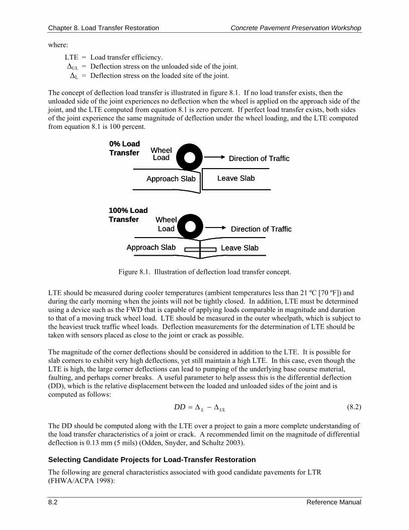
Chapter 8. Load Transfer Restoration Concrete Pavement Preservation Workshop
8.2 Reference Manual
where:
LTE = Load transfer efficiency. ΔUL = Deflection stress on the unloaded side of the joint. ΔL = Deflection stress on the loaded site of the joint.
The concept of deflection load transfer is illustrated in figure 8.1. If no load transfer exists, then the unloaded side of the joint experiences no deflection when the wheel is applied on the approach side of the joint, and the LTE computed from equation 8.1 is zero percent. If perfect load transfer exists, both sides of the joint experience the same magnitude of deflection under the wheel loading, and the LTE computed from equation 8.1 is 100 percent.
WheelLoad
0% Load Transfer
Direction of Traffic
Approach Slab Leave Slab
100% Load Transfer
Approach Slab
WheelLoad Direction of Traffic
Leave Slab
WheelLoad
0% Load Transfer
Direction of Traffic
Approach Slab Leave Slab
100% Load Transfer
Approach Slab
WheelLoad Direction of Traffic
Leave Slab
Figure 8.1. Illustration of deflection load transfer concept.
LTE should be measured during cooler temperatures (ambient temperatures less than 21 ºC [70 ºF]) and during the early morning when the joints will not be tightly closed. In addition, LTE must be determined using a device such as the FWD that is capable of applying loads comparable in magnitude and duration to that of a moving truck wheel load. LTE should be measured in the outer wheelpath, which is subject to the heaviest truck traffic wheel loads. Deflection measurements for the determination of LTE should be taken with sensors placed as close to the joint or crack as possible. The magnitude of the corner deflections should be considered in addition to the LTE. It is possible for slab corners to exhibit very high deflections, yet still maintain a high LTE. In this case, even though the LTE is high, the large corner deflections can lead to pumping of the underlying base course material, faulting, and perhaps corner breaks. A useful parameter to help assess this is the differential deflection (DD), which is the relative displacement between the loaded and unloaded sides of the joint and is computed as follows:
(8.2) The DD should be computed along with the LTE over a project to gain a more complete understanding of the load transfer characteristics of a joint or crack. A recommended limit on the magnitude of differential deflection is 0.13 mm (5 mils) (Odden, Snyder, and Schultz 2003). Selecting Candidate Projects for Load-Transfer Restoration The following are general characteristics associated with good candidate pavements for LTR (FHWA/ACPA 1998):
ULLDD Δ−Δ=
Concrete Pavement Preservation Workshop Chapter 8. Load Transfer Restoration
Reference Manual 8.3
Pavements with structurally adequate slab thickness, but exhibiting significant loss of load transfer due to lack of dowels, poor aggregate interlock, or base/subbase/subgrade erosion.
Relatively young pavements that, because of insufficient slab thickness, excessive joint spacing, inadequate steel reinforcement at transverse cracks, and/or inadequate joint load transfer, are at risk of developing faulting, working cracks, and corner cracks unless load transfer is improved.
In general, the pavement should be in relatively good condition with a limited amount of structural cracking (Bendaña and Yang 1993). Pavements exhibiting significant slab cracking, joint spalling, or materials-related distress such as D-cracking, should not be considered candidates for LTR (Larson, Peterson, and Correa 1998). One set of recommendations on the condition of a joint or crack suitable for LTR is that it exhibits a deflection load transfer of 60 percent or less, faulting greater than 2.5 mm (0.10 in) but less than 6 mm (0.25 in), and differential deflection of 0.25 mm (0.01 in) (FHWA/ACPA 1998). The recommendation from Washington State is that LTR should be considered on pavements that have an average faulting between 3 mm (0.125 in) and 13 mm (0.5 in) and when the number of panels with multiple cracks is less than or equal to 10 percent (Pierce et al. 2003). Caltrans (2006) has similar requirements as Washington State, and also includes differential deflection (0.25 mm [10 mils] or more) and IRI (levels between 2.3 and 3.2 m/km [150 and 200 in/mi]) as additional consideration factors. LTR may also be used in other applications, including at transverse cracks (if the cracks are fairly uniform and have not widened or started faulting) and in preparation for an overlay. In the former, LTR helps to maintain structural integrity and improves ride quality, and in the latter, LTR can help reduce the incidence and severity of reflection cracking, spalling, and deterioration of the overlay (and may also result in a thinner overlay thickness). 4. LIMITATIONS AND EFFECTIVENESS Load transfer restoration is not a new rehabilitation technique. Georgia first explored LTR on a project on I-75 in 1980 (Gulden and Brown 1985), and Puerto Rico’s experience goes back to at least 1983 (Larson, Peterson, and Correa 1998). In the past decade, many more highway agencies have tried or began using LTR as a pavement preservation technique. An example of a successful dowel bar retrofit program can be found in Washington State. Since 1992, Washington State has used LTR to rehabilitate many miles of JPCP with good success (Pierce 1994; Pierce 1997). In 2002, after an assessment of the first 10 years of experience with dowel retrofit projects, Washington State reported that although some isolated distress has appeared on some of the earlier constructed projects, overall the dowel bar retrofit projects are performing very well (Pierce et al. 2003). Puerto Rico has also reported good performance on many miles of retrofitted dowel bars. A review of over 7,000 dowel bars installed 8 years earlier indicated that fewer than 0.5 percent of the repairs had failed (FHWA/ACPA 1998). While there has been good documented success with this technique, a few states have experienced some problems with their initial LTR trials. For example, in 1999 and 2000, Wisconsin installed retrofitted dowel bars on portions of Interstate 39. In 2001, a review of these projects found that the patch material used to backfill the slots was deteriorating at the joints in many parts of the project (Bischoff and Toepel 2002). In response to these observed material problems, Wisconsin constructed 15 additional test sections and three control sections in 2001 to study patch materials, dowel bar materials, and the effects of sealed and unsealed joints on dowel bar retrofit projects (Bischoff and Toepel 2002). After 1 year of service, the performance of the test sections was reviewed. While two patching materials showed some debonding and microcracking due to shrinkage, the other patch materials were found to be performing well with no distresses (Bischoff and Toepel 2002).
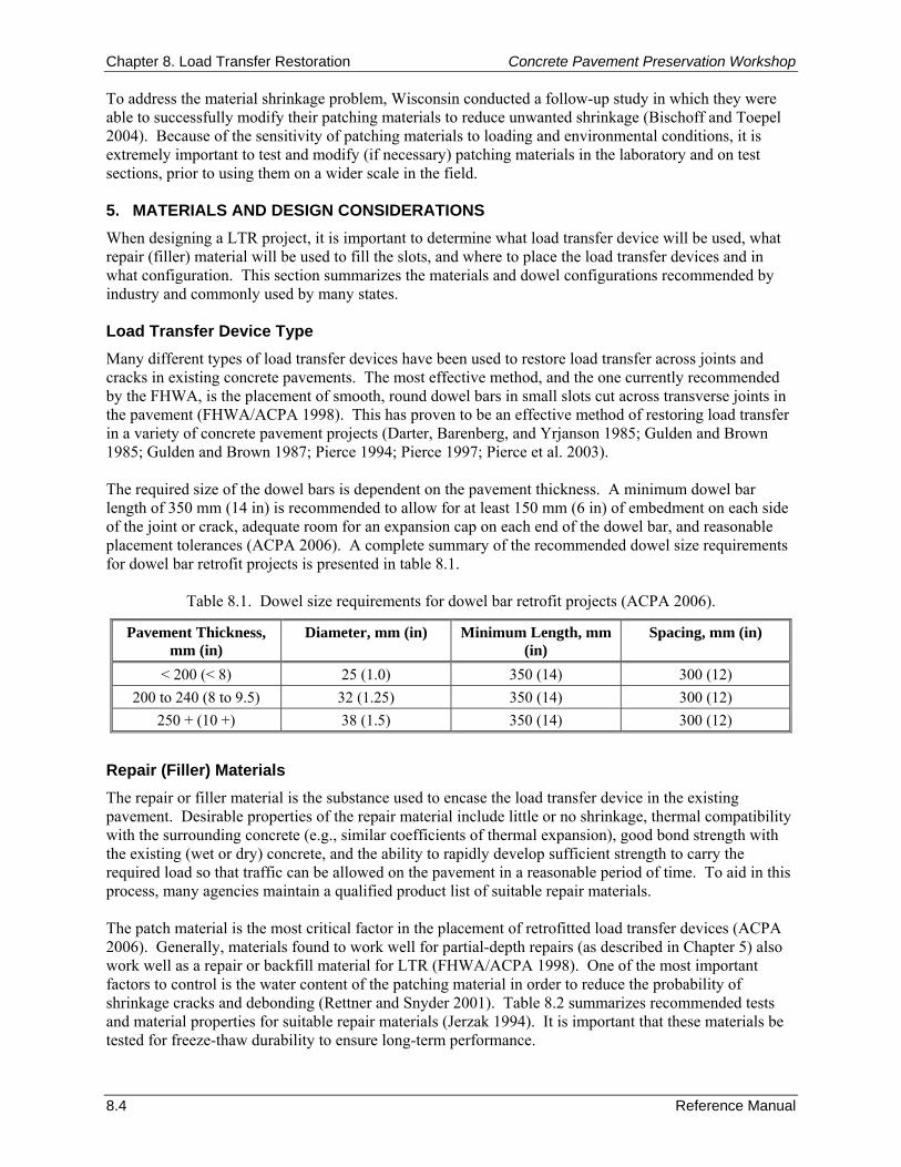
Chapter 8. Load Transfer Restoration Concrete Pavement Preservation Workshop
8.4 Reference Manual
To address the material shrinkage problem, Wisconsin conducted a follow-up study in which they were able to successfully modify their patching materials to reduce unwanted shrinkage (Bischoff and Toepel 2004). Because of the sensitivity of patching materials to loading and environmental conditions, it is extremely important to test and modify (if necessary) patching materials in the laboratory and on test sections, prior to using them on a wider scale in the field. 5. MATERIALS AND DESIGN CONSIDERATIONS When designing a LTR project, it is important to determine what load transfer device will be used, what repair (filler) material will be used to fill the slots, and where to place the load transfer devices and in what configuration. This section summarizes the materials and dowel configurations recommended by industry and commonly used by many states. Load Transfer Device Type Many different types of load transfer devices have been used to restore load transfer across joints and cracks in existing concrete pavements. The most effective method, and the one currently recommended by the FHWA, is the placement of smooth, round dowel bars in small slots cut across transverse joints in the pavement (FHWA/ACPA 1998). This has proven to be an effective method of restoring load transfer in a variety of concrete pavement projects (Darter, Barenberg, and Yrjanson 1985; Gulden and Brown 1985; Gulden and Brown 1987; Pierce 1994; Pierce 1997; Pierce et al. 2003). The required size of the dowel bars is dependent on the pavement thickness. A minimum dowel bar length of 350 mm (14 in) is recommended to allow for at least 150 mm (6 in) of embedment on each side of the joint or crack, adequate room for an expansion cap on each end of the dowel bar, and reasonable placement tolerances (ACPA 2006). A complete summary of the recommended dowel size requirements for dowel bar retrofit projects is presented in table 8.1.
Table 8.1. Dowel size requirements for dowel bar retrofit projects (ACPA 2006).
Pavement Thickness, mm (in)
Diameter, mm (in) Minimum Length, mm (in)
Spacing, mm (in)
< 200 (< 8) 25 (1.0) 350 (14) 300 (12) 200 to 240 (8 to 9.5) 32 (1.25) 350 (14) 300 (12)
250 + (10 +) 38 (1.5) 350 (14) 300 (12)
Repair (Filler) Materials The repair or filler material is the substance used to encase the load transfer device in the existing pavement. Desirable properties of the repair material include little or no shrinkage, thermal compatibility with the surrounding concrete (e.g., similar coefficients of thermal expansion), good bond strength with the existing (wet or dry) concrete, and the ability to rapidly develop sufficient strength to carry the required load so that traffic can be allowed on the pavement in a reasonable period of time. To aid in this process, many agencies maintain a qualified product list of suitable repair materials. The patch material is the most critical factor in the placement of retrofitted load transfer devices (ACPA 2006). Generally, materials found to work well for partial-depth repairs (as described in Chapter 5) also work well as a repair or backfill material for LTR (FHWA/ACPA 1998). One of the most important factors to control is the water content of the patching material in order to reduce the probability of shrinkage cracks and debonding (Rettner and Snyder 2001). Table 8.2 summarizes recommended tests and material properties for suitable repair materials (Jerzak 1994). It is important that these materials be tested for freeze-thaw durability to ensure long-term performance.
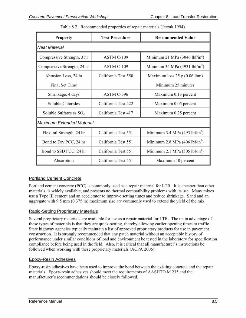
Concrete Pavement Preservation Workshop Chapter 8. Load Transfer Restoration
Reference Manual 8.5
Table 8.2. Recommended properties of repair materials (Jerzak 1994).
Property Test Procedure Recommended Value
Neat Material
Compressive Strength, 3 hr ASTM C-109 Minimum 21 MPa (3046 lbf/in2)
Compressive Strength, 24 hr ASTM C-109 Minimum 34 MPa (4931 lbf/in2)
Abrasion Loss, 24 hr California Test 550 Maximum loss 25 g (0.06 lbm)
Final Set Time Minimum 25 minutes
Shrinkage, 4 days ASTM C-596 Maximum 0.13 percent
Soluble Chlorides California Test 422 Maximum 0.05 percent
Soluble Sulfates as SO4 California Test 417 Maximum 0.25 percent
Maximum Extended Material
Flexural Strength, 24 hr California Test 551 Minimum 3.4 MPa (493 lbf/in2)
Bond to Dry PCC, 24 hr California Test 551 Minimum 2.8 MPa (406 lbf/in2)
Bond to SSD PCC, 24 hr California Test 551 Minimum 2.1 MPa (305 lbf/in2)
Absorption California Test 551 Maximum 10 percent
Portland Cement Concrete
Portland cement concrete (PCC) is commonly used as a repair material for LTR. It is cheaper than other materials, is widely available, and presents no thermal compatibility problems with its use. Many mixes use a Type III cement and an accelerator to improve setting times and reduce shrinkage. Sand and an aggregate with 9.5 mm (0.375 in) maximum size are commonly used to extend the yield of the mix. Rapid-Setting Proprietary Materials
Several proprietary materials are available for use as a repair material for LTR. The main advantage of these types of materials is that they are quick-setting, thereby allowing earlier opening times to traffic. State highway agencies typically maintain a list of approved proprietary products for use in pavement construction. It is strongly recommended that any patch material without an acceptable history of performance under similar conditions of load and environment be tested in the laboratory for specification compliance before being used in the field. Also, it is critical that all manufacturer’s instructions be followed when working with these proprietary materials (ACPA 2006). Epoxy-Resin Adhesives
Epoxy-resin adhesives have been used to improve the bond between the existing concrete and the repair materials. Epoxy-resin adhesives should meet the requirements of AASHTO M 235 and the manufacturer’s recommendations should be closely followed.
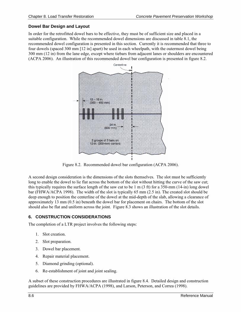
Chapter 8. Load Transfer Restoration Concrete Pavement Preservation Workshop
8.6 Reference Manual
Dowel Bar Design and Layout In order for the retrofitted dowel bars to be effective, they must be of sufficient size and placed in a suitable configuration. While the recommended dowel dimensions are discussed in table 8.1, the recommended dowel configuration is presented in this section. Currently it is recommended that three to four dowels (spaced 300 mm [12 in] apart) be used in each wheelpath, with the outermost dowel being 300 mm (12 in) from the lane edge, except where tiebars from adjacent lanes or shoulders are encountered (ACPA 2006). An illustration of this recommended dowel bar configuration is presented in figure 8.2.
Figure 8.2. Recommended dowel bar configuration (ACPA 2006).
A second design consideration is the dimensions of the slots themselves. The slot must be sufficiently long to enable the dowel to lie flat across the bottom of the slot without hitting the curve of the saw cut; this typically requires the surface length of the saw cut to be 1 m (3 ft) for a 350-mm (14-in) long dowel bar (FHWA/ACPA 1998). The width of the slot is typically 65 mm (2.5 in). The created slot should be deep enough to position the centerline of the dowel at the mid-depth of the slab, allowing a clearance of approximately 13 mm (0.5 in) beneath the dowel bar for placement on chairs. The bottom of the slot should also be flat and uniform across the joint. Figure 8.3 shows an illustration of the slot details. 6. CONSTRUCTION CONSIDERATIONS The completion of a LTR project involves the following steps:
1. Slot creation.
2. Slot preparation.
3. Dowel bar placement.
4. Repair material placement.
5. Diamond grinding (optional).
6. Re-establishment of joint and joint sealing. A subset of these construction procedures are illustrated in figure 8.4. Detailed design and construction guidelines are provided by FHWA/ACPA (1998), and Larson, Peterson, and Correa (1998).
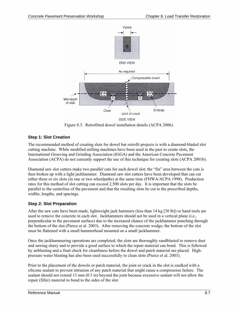
Concrete Pavement Preservation Workshop Chapter 8. Load Transfer Restoration
Reference Manual 8.7
Figure 8.3. Retrofitted dowel installation details (ACPA 2006).
Step 1: Slot Creation The recommended method of creating slots for dowel bar retrofit projects is with a diamond-bladed slot cutting machine. While modified milling machines have been used in the past to create slots, the International Grooving and Grinding Association (IGGA) and the American Concrete Pavement Association (ACPA) do not currently support the use of this technique for creating slots (ACPA 2001b). Diamond saw slot cutters make two parallel cuts for each dowel slot; the “fin” area between the cuts is then broken up with a light jackhammer. Diamond saw slot cutters have been developed that can cut either three or six slots (in one or two wheelpaths) at the same time (FHWA/ACPA 1998). Production rates for this method of slot cutting can exceed 2,500 slots per day. It is important that the slots be parallel to the centerline of the pavement and that the resulting slots be cut to the prescribed depths, widths, lengths, and spacings. Step 2: Slot Preparation After the saw cuts have been made, lightweight jack hammers (less than 14 kg [30 lb]) or hand tools are used to remove the concrete in each slot. Jackhammers should not be used in a vertical plane (i.e., perpendicular to the pavement surface) due to the increased chance of the jackhammer punching through the bottom of the slot (Pierce et al. 2003). After removing the concrete wedge, the bottom of the slot must be flattened with a small hammerhead mounted on a small jackhammer. Once the jackhammering operations are completed, the slots are thoroughly sandblasted to remove dust and sawing slurry and to provide a good surface to which the repair material can bond. This is followed by airblasting and a final check for cleanliness before the dowel and patch material are placed. High-pressure water blasting has also been used successfully to clean slots (Pierce et al. 2003). Prior to the placement of the dowels or patch material, the joint or crack in the slot is caulked with a silicone sealant to prevent intrusion of any patch material that might cause a compression failure. The sealant should not extend 13 mm (0.5 in) beyond the joint because excessive sealant will not allow the repair (filler) material to bond to the sides of the slot.
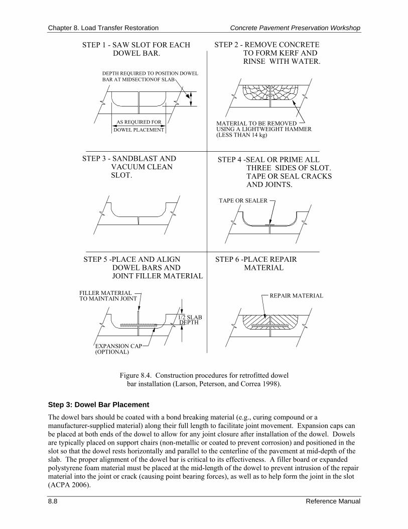
Chapter 8. Load Transfer Restoration Concrete Pavement Preservation Workshop
8.8 Reference Manual
STEP 1 - SAW SLOT FOR EACHDOWEL BAR.
STEP 2 - REMOVE CONCRETETO FORM KERF ANDRINSE WITH WATER.
STEP 3 - SANDBLAST ANDVACUUM CLEANSLOT.
STEP 4 -SEAL OR PRIME ALLTHREE SIDES OF SLOT.TAPE OR SEAL CRACKSAND JOINTS.
STEP 5 -PLACE AND ALIGNDOWEL BARS AND JOINT FILLER MATERIAL
STEP 6 -PLACE REPAIRMATERIAL
DEPTH REQUIRED TO POSITION DOWEL BAR AT MIDSECTIONOF SLAB
AS REQUIRED FORDOWEL PLACEMENT
MATERIAL TO BE REMOVED USING A LIGHTWEIGHT HAMMER(LESS THAN 14 kg)
TAPE OR SEALER
FILLER MATERIALTO MAINTAIN JOINT
EXPANSION CAP(OPTIONAL)
1/2 SLABDEPTH
REPAIR MATERIAL
Figure 8.4. Construction procedures for retrofitted dowel bar installation (Larson, Peterson, and Correa 1998).
Step 3: Dowel Bar Placement The dowel bars should be coated with a bond breaking material (e.g., curing compound or a manufacturer-supplied material) along their full length to facilitate joint movement. Expansion caps can be placed at both ends of the dowel to allow for any joint closure after installation of the dowel. Dowels are typically placed on support chairs (non-metallic or coated to prevent corrosion) and positioned in the slot so that the dowel rests horizontally and parallel to the centerline of the pavement at mid-depth of the slab. The proper alignment of the dowel bar is critical to its effectiveness. A filler board or expanded polystyrene foam material must be placed at the mid-length of the dowel to prevent intrusion of the repair material into the joint or crack (causing point bearing forces), as well as to help form the joint in the slot (ACPA 2006).
Concrete Pavement Preservation Workshop Chapter 8. Load Transfer Restoration
Reference Manual 8.9
Step 4: Repair Material Placement Once the dowel has been placed and the filler board material is in position, the repair material is then placed in the slot according to the manufacturer’s recommendations. The repair material should be placed in a manner that will not cause movement of the dowel bar within the slot (i.e., the repair material should not be dumped onto the slots) (Pierce et al. 2003). Placing the repair material on the surface adjacent to the slot and shoving it towards and into the slot results in minimal dowel movement (Pierce et al. 2003). A small spud vibrator (i.e., ≤ 25 mm [1.0 in] in diameter) should be used to consolidate the patching material. The patching material in the dowel bar slots should not be overworked, which would otherwise cause migration of the fine material to the surface (Pierce et al. 2003). After consolidation and finishing, a curing compound should be placed on the patching material to minimize shrinkage. Depending upon the type of repair material, the pavement may be opened to traffic in as little as a few hours. Recent studies have shown that the minimum compressive strength required to open a repair to traffic is about 13.7 MPa (2,000 lbf/in2) for slabs 200 mm (8 in) or thicker (FHWA/ACPA 1998). Step 5: Diamond Grinding (Optional) Rehabilitation techniques such as load-transfer restoration may result in increased roughness if not finished properly. This is typically due to differences in elevation between the finished repair area and the existing pavement, or perhaps due to shrinkage or settlement of the repair material. Consequently, after the installation of retrofitted dowel bars, the entire pavement project is often diamond ground to provide a smooth-riding surface. Step 6: Re-Establishment of Joint and Joint Sealing After the material has cured and the surface diamond ground, the transverse joint should be re-established by sawing over the length of the joint and through the filler board. The joint should then be prepared and sealed as described in Chapter 10. 7. QUALITY CONTROL As with any pavement project, the performance of LTR projects is greatly dependent on the quality of the utilized materials and construction procedures. Paying close attention to this quality during construction greatly increases the chances of minimizing premature failures on LTR projects. An excellent source for QC recommendations is a recently published paper in which a comprehensive set of construction-related recommendations and lessons-learned are summarized (Pierce et al. 2003). These recommendations are based on 10 years of LTR experience in Washington State. The remainder of this section is largely based on the recommendations summarized in the report by Pierce et al. (2003) and in the FHWA’s Dowel-Bar Retrofit for Portland Cement Concrete Pavements Checklist (FHWA 2005). Preliminary Responsibilities Prior to the start of construction procedures, the agency should review pertinent project-related documents, the project’s current condition, and materials to be used on the project. The following specific lists of items are provided as a model QC checklist for these preliminary items. Document Review
All of the following documents should be reviewed prior to the start of any construction activities. Any suspected problems should be identified and reconciled as part of the preliminary review process.

Chapter 8. Load Transfer Restoration Concrete Pavement Preservation Workshop
8.10 Reference Manual
Bid/project specifications and design.
Special provisions.
Agency application requirements.
Traffic control plan.
Manufacturer’s installation instructions for patch materials.
Material safety data sheets (MSDS). Project Review
An updated review of the current project’s condition is warranted to ensure that the project is still a viable candidate for LTR. Specifically, the following should be verified or checked as part of the project review process:
Verify that the pavement conditions have not significantly changed since the project was designed.
Verify that the pavement is structurally sound. A significant amount of slab cracking and/or corner breaks are indicators of structural deficiencies.
Check estimated quantities for dowel bar retrofit. Review of Materials
In preparation for the construction project, the following list summarizes many of the material-related checklist items that should be checked or reviewed:
Verify that dowel slot cementing grout meets specification requirements.
Verify that the dowel slot cementing grout is from an approved source or listed on agency qualified products list (QPL) (if required).
Verify that the component materials for the dowel slot cementing grout have been sampled, tested, and approved prior to installation as required by contact documents.
Verify that the additional or extender aggregates have been properly produced, with acceptable quality.
Verify that the material packaging is not damaged (i.e., leaking, torn, or pierced).
Verify that caulking filler meets specification requirements.
Verify that dowels, dowel bar chairs, and endcaps meet specification requirements.
Verify that dowel bars are properly coated with epoxy (or other approved material) and free of any minor surface damage in accordance with contract documents.
Verify that curing compound meets specification requirements.
Verify that joint/crack re-former material (compressible insert) meets specification requirements (typically polystyrene foam board, 12 mm [1/2 in] thick).
Verify that joint sealant material meets specification requirements.
Verify that all sufficient quantities of materials are on hand for completion of project.
Ensure that all material certifications required by contract documents have been provided to the agency prior to construction.

Concrete Pavement Preservation Workshop Chapter 8. Load Transfer Restoration
Reference Manual 8.11
Inspection of Equipment
Prior to beginning construction, all construction equipment must be examined. The following are equipment-related items that should be checked:
Verify that the slot sawing machine is of sufficient weight, horsepower, and configuration to cut the specified number of slots per wheelpath to the depth shown on the plans.
Verify that jackhammers for removing concrete are limited to a maximum rated weight of 14 kg (30 lb).
Verify that the sandblasting unit for cleaning slots is adjusted for correct sand rate and has oil and moisture filters/traps.
Verify that air compressors have sufficient pressure and volume to adequately remove all dust and debris from slots and meet agency requirements.
For auger-type mixing equipment used to mix repair materials, ensure that auger flights or paddles are kept free of material buildup, which can cause inefficient mixing operations.
Ensure that volumetric mixing equipment (e.g., mobile mixers) are kept in good condition and calibrated on a regular basis to properly proportion mixes.
Ensure that material test equipment required by the specifications is all available on site and in proper working condition (e.g., slump cone, pressure-type air meter, cylinder molds and lids, rod, mallet, ruler, 3-m [10-ft] straightedge).
Verify that vibrators are the size specified in the contract documents (typically 25 mm [1 in] in diameter or less) and are operating correctly.
Verify that the concrete testing technician meets the requirements of the contract document for training/certification.
Ensure that sufficient storage area is available on the project site specifically designated for the storage of concrete cylinders.
Weather Requirements
The weather conditions at time of construction can have a large impact on the performance of the LTR technique. Specifically, the following weather-related items should be checked immediately prior to construction:
Review manufacturer installation instructions for requirements specific to the repair material used.
Air and surface temperature meets manufacturer and all agency requirements (typically 4 °C [40 °F] and above) for concrete placement.
Neither dowel bar installation nor patching should proceed if rain is imminent. Traffic Control
To manage the flow of traffic through the work zone, the following traffic-related items should be checked or verified:
Verify that the signs and devices used match the traffic control plan presented in the contract documents.
Verify that the set-up complies with the Federal or local agency Manual on Uniform Traffic Control Devices (MUTCD) or local agency procedures.
Chapter 8. Load Transfer Restoration Concrete Pavement Preservation Workshop
8.12 Reference Manual
Verify that flaggers are trained/qualified according to contract documents and agency requirements.
Verify that unsafe conditions, if any, are reported to a supervisor.
Ensure that traffic is not opened to the repaired pavement until the backfill material has attained the specified strength as required by the contract documents.
Verify that signs are removed or covered when they are no longer needed. Project Inspection Responsibilities Cutting Slots
During the slot creation construction step, the inspector should ensure that:
Slots are cut parallel to each other, and to the centerline of the roadway within the maximum tolerance permitted by the contract documents, typically 6 mm (1/4 in) per 300 mm (12 in) of dowel bar length.
The number of slots per wheelpath (typically 3 or 4) is in agreement with contract documents.
Slots are aligned to miss any existing longitudinal cracks.
The cut slot length extends the proper distance on each side of the joint/crack, as required by the contract documents. This is especially important for skewed joints and cracks.
Slots are sawed to sufficient depth so that the center of the dowel bar is placed at the mid-depth of the pavement. Slots that are cut too deep will contribute to corner cracks when traffic loads are applied.
Slot widths should be sized to be the exact width of the dowel bar chairs. Removing Material from Slots
It should be verified that concrete fin removal is conducted with only lightweight 14 kg (30 lb) jackhammers. During the process of removing material from the slots, the contractor should take extra care to prevent the jackhammer from punching through the bottom of the slot. The bottom of the slots should then be smoothed and leveled using a lightweight bush hammer. Slot Cleaning and Preparation
The following should be closely inspected when cleaning the slots and the adjacent area and preparing the slots prior to the placement of the dowels:
After concrete removal, the slots should be prepared by sandblasting. A physical check of the slot’s cleanliness (using a tool such as a scraper) should be made to ensure no slurry residue remains on the sides of slots.
After sandblasting, the slots should be cleaned using air blasting. A second air blasting may be required immediately before placement of dowel slot cementing grout if slots are left open for a duration exceeding that permitted in the contract documents.
Concrete chunks, dirt, debris, and slurry residue should be cleaned 1.0 to 1.2 meters (3 to 4 feet) away from the slot’s perimeter. This practice minimizes the possibility of reintroducing unwanted material into the slot during subsequent operations.
The existing joint/crack is sealed with an approved caulking filler material along the bottom and sides of the slot to prevent the repair material from entering the joint/crack. Special care must be taken to ensure that the sealant does not extend 13 mm (0.5 in) beyond the joint (i.e., into the slot).
Concrete Pavement Preservation Workshop Chapter 8. Load Transfer Restoration
Reference Manual 8.13
Placement of Dowel Bars
During the placement of dowels into the cut slots, QC inspections should ensure that:
Plastic endcaps are placed on each end of the dowel bar to account for pavement expansion as required by the contract documents.
Dowel bars are completely coated with an approved compound prior to placing into chairs. Dowel bars that have a factory-applied coating should be free of dirt and debris, and free of nicks and abrasions. The factory-applied coating should be clearly visible; otherwise, an additional application of an approved material must be applied. Dowel bars should not be coated once they have been placed in the slots as the sides and bottom of the slots will become contaminated.
Proper clearance is maintained between the supported dowel bar and the sidewalls, ends, and bottom of the cut slot in accordance with contract documents.
Joint forming material (foam core insert) is placed at mid-point of each bar and in line with the joint/crack, to allow for expansion and to re-form the joint/crack.
The chairs placed on the dowel bars are strong enough to allow full support of the dowel bar. Chairs should allow at least 13 mm (0.5 in) clearance between the bottom of the dowel and the bottom of the slot.
End caps allow at least 6 mm (0.25 in) of movement at each end of the bar. End caps placed on each end of the bar reduce the risk of dowel bar lockup at negligible extra cost.
Dowels are centered across the joint/crack such that at least 175 mm (7 in) of the dowel extends on each side.
Dowels are placed within the following tolerances:
− Placed within 25 mm (1 in) of the center of the existing pavement depth.
− Centered over the transverse joint with a minimum embedment of 175 mm (7 in).
− Placed parallel to the centerline and within the plane of the roadway surface.
− Placed to a horizontal tolerance of ± 13 mm (0.5 in), vertical tolerance of ± 13 mm (0.5 in), and skew from parallel (per 450 mm [18 in]) of ± 13 mm (0.5 in). Dowel bars placed outside of the acceptable tolerances can cause joint lock up that leads to cracking.
Mixing, Placing, Finishing, and Curing of Repair Material
To achieve a well-performing LTR project, it is imperative that good methods and procedures be used when mixing, placing, finishing, and curing the chosen repair material. Specifically, the following should be ensured during construction:
Repair materials are being mixed in accordance with the material manufacturer’s instructions.
Quantities of repair materials being mixed are small, to prevent material from setting prematurely.
Concrete surfaces, including the bottom of the slot, are dry.
Material is consolidated using small, hand-held vibrators, which do not touch the dowel bar assembly during consolidation. Inspectors should also ensure that the grout material is not over consolidated. Each slot should only require two to four short, vertical penetrations of a small diameter spud vibrator.
Repair material is finished flush with surrounding concrete, using an outward motion to prevent pulling material away from patch boundaries. Material is finished slightly “humped” if diamond grinding is to be employed.
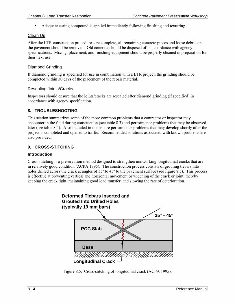
Chapter 8. Load Transfer Restoration Concrete Pavement Preservation Workshop
8.14 Reference Manual
Adequate curing compound is applied immediately following finishing and texturing. Clean Up
After the LTR construction procedures are complete, all remaining concrete pieces and loose debris on the pavement should be removed. Old concrete should be disposed of in accordance with agency specifications. Mixing, placement, and finishing equipment should be properly cleaned in preparation for their next use. Diamond Grinding
If diamond grinding is specified for use in combination with a LTR project, the grinding should be completed within 30 days of the placement of the repair material. Resealing Joints/Cracks
Inspectors should ensure that the joints/cracks are resealed after diamond grinding (if specified) in accordance with agency specification. 8. TROUBLESHOOTING This section summarizes some of the more common problems that a contractor or inspector may encounter in the field during construction (see table 8.3) and performance problems that may be observed later (see table 8.4). Also included in the list are performance problems that may develop shortly after the project is completed and opened to traffic. Recommended solutions associated with known problems are also provided. 9. CROSS-STITCHING Introduction Cross-stitching is a preservation method designed to strengthen nonworking longitudinal cracks that are in relatively good condition (ACPA 1995). The construction process consists of grouting tiebars into holes drilled across the crack at angles of 35º to 45º to the pavement surface (see figure 8.5). This process is effective at preventing vertical and horizontal movement or widening of the crack or joint, thereby keeping the crack tight, maintaining good load transfer, and slowing the rate of deterioration.
Deformed Tiebars Inserted andGrouted Into Drilled Holes(typically 19 mm bars)
PCC Slab
35º – 45º
Longitudinal Crack
Base
Figure 8.5. Cross-stitching of longitudinal crack (ACPA 1995).
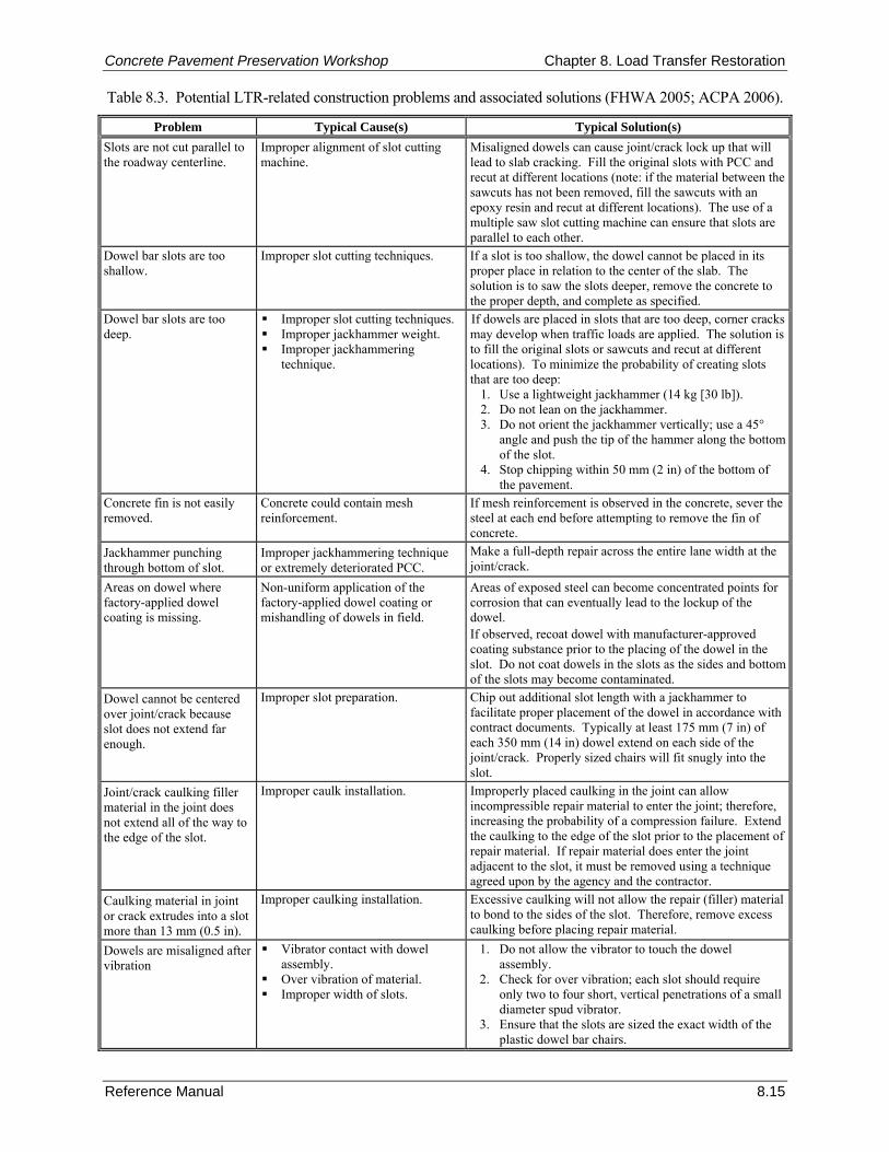
Concrete Pavement Preservation Workshop Chapter 8. Load Transfer Restoration
Reference Manual 8.15
Table 8.3. Potential LTR-related construction problems and associated solutions (FHWA 2005; ACPA 2006).
Problem Typical Cause(s) Typical Solution(s) Slots are not cut parallel to the roadway centerline.
Improper alignment of slot cutting machine.
Misaligned dowels can cause joint/crack lock up that will lead to slab cracking. Fill the original slots with PCC and recut at different locations (note: if the material between the sawcuts has not been removed, fill the sawcuts with an epoxy resin and recut at different locations). The use of a multiple saw slot cutting machine can ensure that slots are parallel to each other.
Dowel bar slots are too shallow.
Improper slot cutting techniques. If a slot is too shallow, the dowel cannot be placed in its proper place in relation to the center of the slab. The solution is to saw the slots deeper, remove the concrete to the proper depth, and complete as specified.
Dowel bar slots are too deep.
Improper slot cutting techniques. Improper jackhammer weight. Improper jackhammering
technique.
If dowels are placed in slots that are too deep, corner cracks may develop when traffic loads are applied. The solution is to fill the original slots or sawcuts and recut at different locations). To minimize the probability of creating slots that are too deep:
1. Use a lightweight jackhammer (14 kg [30 lb]). 2. Do not lean on the jackhammer. 3. Do not orient the jackhammer vertically; use a 45°
angle and push the tip of the hammer along the bottom of the slot.
4. Stop chipping within 50 mm (2 in) of the bottom of the pavement.
Concrete fin is not easily removed.
Concrete could contain mesh reinforcement.
If mesh reinforcement is observed in the concrete, sever the steel at each end before attempting to remove the fin of concrete.
Jackhammer punching through bottom of slot.
Improper jackhammering technique or extremely deteriorated PCC.
Make a full-depth repair across the entire lane width at the joint/crack.
Areas on dowel where factory-applied dowel coating is missing.
Non-uniform application of the factory-applied dowel coating or mishandling of dowels in field.
Areas of exposed steel can become concentrated points for corrosion that can eventually lead to the lockup of the dowel. If observed, recoat dowel with manufacturer-approved coating substance prior to the placing of the dowel in the slot. Do not coat dowels in the slots as the sides and bottom of the slots may become contaminated.
Dowel cannot be centered over joint/crack because slot does not extend far enough.
Improper slot preparation. Chip out additional slot length with a jackhammer to facilitate proper placement of the dowel in accordance with contract documents. Typically at least 175 mm (7 in) of each 350 mm (14 in) dowel extend on each side of the joint/crack. Properly sized chairs will fit snugly into the slot.
Joint/crack caulking filler material in the joint does not extend all of the way to the edge of the slot.
Improper caulk installation. Improperly placed caulking in the joint can allow incompressible repair material to enter the joint; therefore, increasing the probability of a compression failure. Extend the caulking to the edge of the slot prior to the placement of repair material. If repair material does enter the joint adjacent to the slot, it must be removed using a technique agreed upon by the agency and the contractor.
Caulking material in joint or crack extrudes into a slot more than 13 mm (0.5 in).
Improper caulking installation. Excessive caulking will not allow the repair (filler) material to bond to the sides of the slot. Therefore, remove excess caulking before placing repair material.
Dowels are misaligned after vibration
Vibrator contact with dowel assembly.
Over vibration of material. Improper width of slots.
1. Do not allow the vibrator to touch the dowel assembly.
2. Check for over vibration; each slot should require only two to four short, vertical penetrations of a small diameter spud vibrator.
3. Ensure that the slots are sized the exact width of the plastic dowel bar chairs.
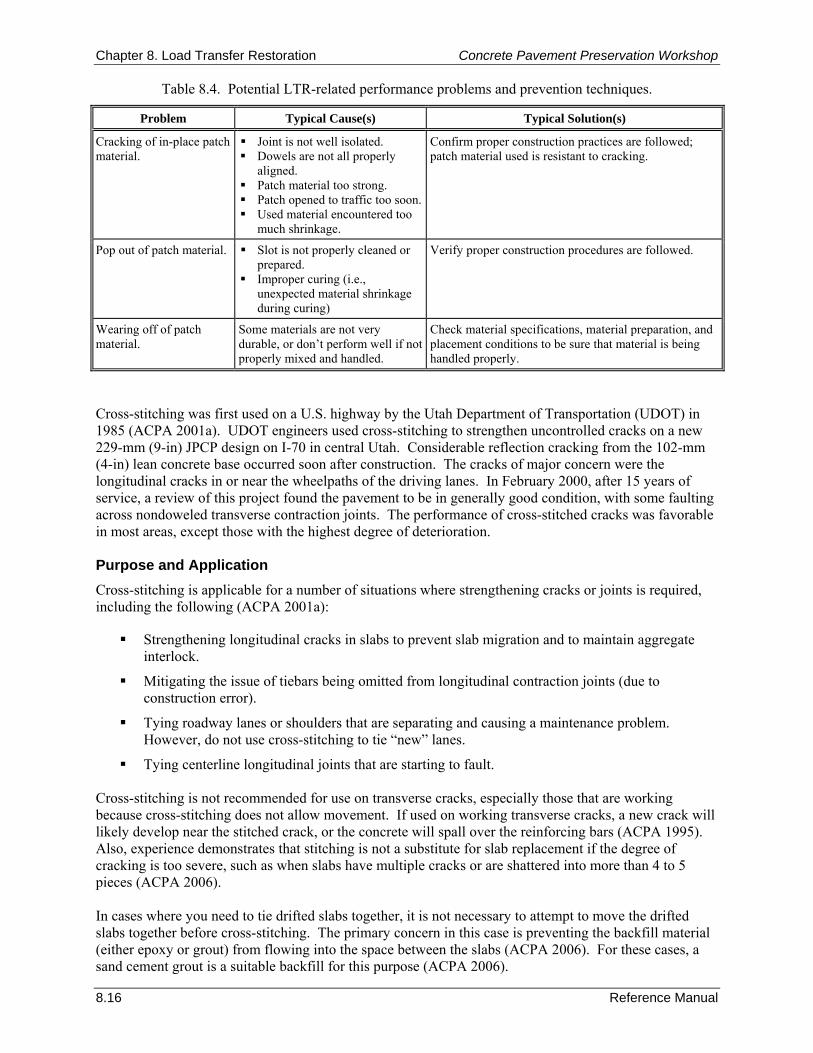
Chapter 8. Load Transfer Restoration Concrete Pavement Preservation Workshop
8.16 Reference Manual
Table 8.4. Potential LTR-related performance problems and prevention techniques.
Problem Typical Cause(s) Typical Solution(s)
Cracking of in-place patch material.
Joint is not well isolated. Dowels are not all properly
aligned. Patch material too strong. Patch opened to traffic too soon. Used material encountered too
much shrinkage.
Confirm proper construction practices are followed; patch material used is resistant to cracking.
Pop out of patch material. Slot is not properly cleaned or prepared.
Improper curing (i.e., unexpected material shrinkage during curing)
Verify proper construction procedures are followed.
Wearing off of patch material.
Some materials are not very durable, or don’t perform well if not properly mixed and handled.
Check material specifications, material preparation, and placement conditions to be sure that material is being handled properly.
Cross-stitching was first used on a U.S. highway by the Utah Department of Transportation (UDOT) in 1985 (ACPA 2001a). UDOT engineers used cross-stitching to strengthen uncontrolled cracks on a new 229-mm (9-in) JPCP design on I-70 in central Utah. Considerable reflection cracking from the 102-mm (4-in) lean concrete base occurred soon after construction. The cracks of major concern were the longitudinal cracks in or near the wheelpaths of the driving lanes. In February 2000, after 15 years of service, a review of this project found the pavement to be in generally good condition, with some faulting across nondoweled transverse contraction joints. The performance of cross-stitched cracks was favorable in most areas, except those with the highest degree of deterioration. Purpose and Application Cross-stitching is applicable for a number of situations where strengthening cracks or joints is required, including the following (ACPA 2001a):
Strengthening longitudinal cracks in slabs to prevent slab migration and to maintain aggregate interlock.
Mitigating the issue of tiebars being omitted from longitudinal contraction joints (due to construction error).
Tying roadway lanes or shoulders that are separating and causing a maintenance problem. However, do not use cross-stitching to tie “new” lanes.
Tying centerline longitudinal joints that are starting to fault. Cross-stitching is not recommended for use on transverse cracks, especially those that are working because cross-stitching does not allow movement. If used on working transverse cracks, a new crack will likely develop near the stitched crack, or the concrete will spall over the reinforcing bars (ACPA 1995). Also, experience demonstrates that stitching is not a substitute for slab replacement if the degree of cracking is too severe, such as when slabs have multiple cracks or are shattered into more than 4 to 5 pieces (ACPA 2006). In cases where you need to tie drifted slabs together, it is not necessary to attempt to move the drifted slabs together before cross-stitching. The primary concern in this case is preventing the backfill material (either epoxy or grout) from flowing into the space between the slabs (ACPA 2006). For these cases, a sand cement grout is a suitable backfill for this purpose (ACPA 2006).
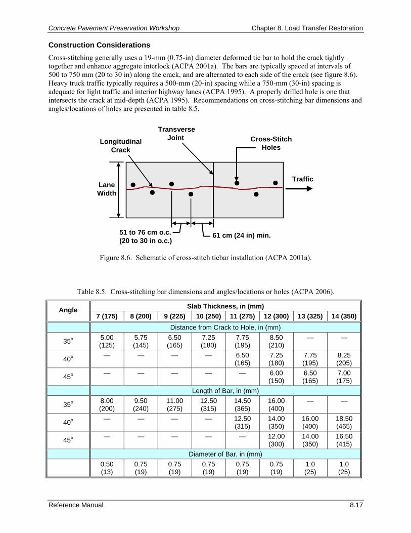
Concrete Pavement Preservation Workshop Chapter 8. Load Transfer Restoration
Reference Manual 8.17
61 cm (24 in) min.
LongitudinalCrack
TransverseJoint
51 to 76 cm o.c.(20 to 30 in o.c.)
Cross-StitchHoles
TrafficLaneWidth
Construction Considerations Cross-stitching generally uses a 19-mm (0.75-in) diameter deformed tie bar to hold the crack tightly together and enhance aggregate interlock (ACPA 2001a). The bars are typically spaced at intervals of 500 to 750 mm (20 to 30 in) along the crack, and are alternated to each side of the crack (see figure 8.6). Heavy truck traffic typically requires a 500-mm (20-in) spacing while a 750-mm (30-in) spacing is adequate for light traffic and interior highway lanes (ACPA 1995). A properly drilled hole is one that intersects the crack at mid-depth (ACPA 1995). Recommendations on cross-stitching bar dimensions and angles/locations of holes are presented in table 8.5.
Figure 8.6. Schematic of cross-stitch tiebar installation (ACPA 2001a).
Table 8.5. Cross-stitching bar dimensions and angles/locations or holes (ACPA 2006).
Slab Thickness, in (mm) Angle 7 (175) 8 (200) 9 (225) 10 (250) 11 (275) 12 (300) 13 (325) 14 (350)
Distance from Crack to Hole, in (mm)
35o 5.00 (125)
5.75 (145)
6.50 (165)
7.25 (180)
7.75 (195)
8.50 (210)
— —
40o — — — — 6.50 (165)
7.25 (180)
7.75 (195)
8.25 (205)
45o — — — — — 6.00 (150)
6.50 (165)
7.00 (175)
Length of Bar, in (mm)
35o 8.00 (200)
9.50 (240)
11.00 (275)
12.50 (315)
14.50 (365)
16.00 (400)
— —
40o — — — — 12.50 (315)
14.00 (350)
16.00 (400)
18.50 (465)
45o — — — — — 12.00 (300)
14.00 (350)
16.50 (415)
Diameter of Bar, in (mm)
0.50 (13)
0.75 (19)
0.75 (19)
0.75 (19)
0.75 (19)
0.75 (19)
1.0 (25)
1.0 (25)
Chapter 8. Load Transfer Restoration Concrete Pavement Preservation Workshop
8.18 Reference Manual
The process of cross-stitching requires the completion of the following steps and considerations (ACPA 2001a; ACPA 2006):
Drill holes at an angle so that they intersect the crack at mid-depth (it is important to start drilling the hole at a consistent distance from the crack, in order to consistently cross the crack at mid-depth). Select a drill that minimizes damage to the concrete surface, such as a hydraulic powered drill, and select a drill diameter no more than 9.5 mm (0.375 in) larger than the tiebar diameter.
Blow air into the holes to remove dust and debris after drilling.
Pour epoxy into the hole, leaving some volume for the bar to occupy the hole.
Insert the tiebar.
Remove excess epoxy and finish flush with the pavement surface. The pavement may be reopened to traffic as soon as the epoxy has fully set. 10. SUMMARY This chapter provides guidance for properly designing and installing retrofitted dowel bars in concrete pavements. These devices are intended to restore load transfer across joints or cracks that exhibit poor load transfer from one side of the joint or crack to the other. Load transfer restoration is seeing more widespread use as benefits have been found to include a reduction in faulting rates, improvements to overall pavement performance, and extensions to pavement life. Currently, only the use of dowel bars placed in slots are recommended, because they have a good long-term performance record, are reliable, and are effective in reducing faulting. Pavements most suited to dowel bar retrofitting are those that are in relatively good condition (little or no distress), but are exhibiting poor load transfer. The optimum time for the application of this strategy is when the pavement is just beginning to exhibit signs of distress, such as pumping or the onset of faulting. While the chapter primarily focuses on the details of the load-transfer restoration technique, the chapter also contains a brief discussion on the pavement cross-stitching technique, which is used primarily to strengthen nonworking longitudinal cracks that are in relatively good condition (ACPA 2001a). 11. REFERENCES American Concrete Pavement Association (ACPA). 1995. Joint and Crack Sealing and Repair for Concrete Pavements. Technical Bulletin TB012P. American Concrete Pavement Association, Skokie, IL.
American Concrete Pavement Association (ACPA). 2001a. Stitching Concrete Pavement Cracks and Joints. Special Report SR903P. American Concrete Pavement Association, Skokie, IL.
American Concrete Pavement Association (ACPA). 2001b. Load Transfer Restoration: Diamond Saw Slot Cutting vs. Carbide Milling. Special Report SR905P. American Concrete Pavement Association, Skokie, IL.
American Concrete Pavement Association (ACPA). 2006. Concrete Pavement Field Reference - Preservation and Repair. Engineering Bulletin EB239P. American Concrete Pavement Association, Skokie, IL.
Bendaña, L. J. and W-S. Yang. 1993. “Rehabilitation Procedures for Faulted Rigid Pavement.” Transportation Research Record 1388. Transportation Research Board, Washington, DC.
Bischoff, D. and A. Toepel. 2002. Dowel Bar Retrofit–STH 13 Construction & One-Year Performance Report. WI-07-02. Wisconsin Department of Transportation, Madison, WI.
Concrete Pavement Preservation Workshop Chapter 8. Load Transfer Restoration
Reference Manual 8.19
Bischoff, D. and A. Toepel. 2004. Laboratory Testing of Portland Cement Concrete Patch Material, Modified to Reduce or Eliminate Shrinkage. WI-01-04. Wisconsin Department of Transportation, Madison, WI.
California Department of Transportation (Caltrans). 2006. Dowel Bar Retrofit Guidelines. Pavement Tech Notes. California Department of Transportation, Sacramento, CA.
Darter, M. I., E. J. Barenberg, and W. A. Yrjanson. 1985. Joint Repair Methods for Portland Cement Concrete Pavements. National Cooperative Highway Research Program Report 281. Transportation Research Board, Washington, DC.
Federal Highway Administration (FHWA)/American Concrete Pavement Association (ACPA). 1998. Concrete Pavement Rehabilitation: Guide for Load Transfer Restoration. FHWA-SA-97-103, ACPA Bulletin JP001P. Federal Highway Administration, Washington, DC, and American Concrete Pavement Association, Skokie, IL.
Federal Highway Administration (FHWA). 2005. Pavement Preservation Checklist Series #8: Dowel Bar Retrofit for Portland Cement Concrete Pavements. FHWA-IF-03-041. Federal Highway Administration, Washington, DC.
Gulden, W. and D. Brown. 1985. “Establishing Load Transfer In Existing Jointed Concrete Pavements.” Transportation Research Record 1043. Transportation Research Board, Washington, DC.
Gulden, W. and D. Brown. 1987. Improving Load Transfer in Existing Jointed Concrete Pavements. FHWA/RD-82/154. Federal Highway Administration, Washington, DC.
Jerzak, H. 1994. Rapid Set Materials for Repairs to Portland Cement Concrete Pavement and Structures. California Department of Transportation, Sacramento, CA.
Kelleher, K. and R. M. Larson. 1989. “The Design of Plain Doweled Jointed Concrete Pavement.” Proceedings, Fourth International Conference on Concrete Pavement Design and Rehabilitation. Purdue University, West Lafayette, IN.
Larson, R. M., D. Peterson, and A. Correa. 1998. Retrofit Load Transfer, Special Demonstration Project SP-204. FHWA-SA-98-047. Federal Highway Administration, Washington, DC.
Odden, T. R., M. B. Snyder, and A. E. Schultz. 2003. Performance Testing of Experimental Dowel Bar Retrofit Designs, Part 1—Initial Testing. MN/RC-2004-17A. Minnesota Department of Transportation, St. Paul, MN.
Pierce, L. M. 1994. “Portland Cement Concrete Pavement Rehabilitation in Washington State: Case Study.” Transportation Research Record 1449. Transportation Research Board, Washington, DC.
Pierce, L. M. 1997. “Design, Construction, Performance and Future Direction of Dowel Bar Retrofit in Washington State.” Proceedings, Sixth International Purdue Conference on Concrete Pavements, Volume 2. Purdue University, West Lafayette, IN.
Pierce, L. M., J. Uhlmeyer, J. Weston, J. Lovejoy, and J. P. Mahoney. 2003. “Ten-Year Performance of Dowel Bar Retrofit—Application, Performance, and Lessons Learned.” Transportation Research Record 1853. Transportation Research Board, Washington, DC.
Rettner, D. L. and M. B. Snyder. 2001. “An Evaluation of Retrofit Load Transfer Materials and Dowel Bar Configurations.” Proceedings, 7th International Conference on Concrete Pavements, Orlando, FL.

Chapter 8. Load Transfer Restoration Concrete Pavement Preservation Workshop
8.20 Reference Manual
NOTES

Concrete Pavement Preservation Workshop Chapter 9. Diamond Grinding and Grooving
Reference Manual 9.1
CHAPTER 9. DIAMOND GRINDING AND GROOVING 1. LEARNING OUTCOMES This chapter describes recommended procedures for surface restoration of concrete pavements. Upon completion of this chapter, the participants will be able to accomplish the following:
1. Differentiate between diamond grinding and diamond grooving, and list the benefits of each.
2. Identify appropriate blade spacing dimensions for grinding and grooving.
3. Describe recommended construction procedures.
4. Identify typical construction problems and remedies. 2. INTRODUCTION Diamond grinding and diamond grooving are two different surface restoration procedures that are used to correct concrete pavement surface distresses or deficiencies. Each technique addresses a specific pavement shortcoming, and each may be used in conjunction with other pavement preservation techniques as part of a comprehensive pavement preservation program. In some situations, it may be justified to use one of these techniques as the sole preservation technique. 3. PURPOSE AND PROJECT SELECTION Diamond Grinding Diamond grinding is the removal of a thin layer of hardened concrete pavement surface using closely spaced, diamond saw blades mounted on a rotating shaft. Diamond grinding is primarily conducted to restore or improve ride quality by eliminating surface irregularities. Restoring ride quality improves pavement load-carrying capacity and adds value to an in-place pavement (ACPA 2000). Diamond grinding was first used in California in 1965 on a 19-year old section of Interstate 10 to eliminate significant faulting (Neal and Woodstrom 1976). In 1983, concrete pavement restoration (CPR) was conducted on this same pavement section, including the use of additional grinding to restore the rideability and skid resistance of the surface. In addition to diamond grinding, this CPR project included slab replacement, spall repair, and installation of edge drains. In 1997, this pavement was reground for a third time, where it is carrying nearly 2.25 million equivalent single axle load (ESAL) applications per year in the truck lane. Since its first use in 1965, the use of diamond grinding has grown to become a major element of concrete pavement preservation projects. Diamond grinding has been employed on concrete pavement surfaces for a variety of reasons, including the following:
Removal of transverse joint and crack faulting. Removal of wheelpath “rutting” caused by studded tire wear. Removal of permanent slab warping at joints (in very dry climates where significant warping has
occurred). Texturing of a polished pavement surface exhibiting inadequate macrotexture (improving skid
resistance). Improvement of transverse slope to improve surface drainage. Tire/pavement noise abatement.
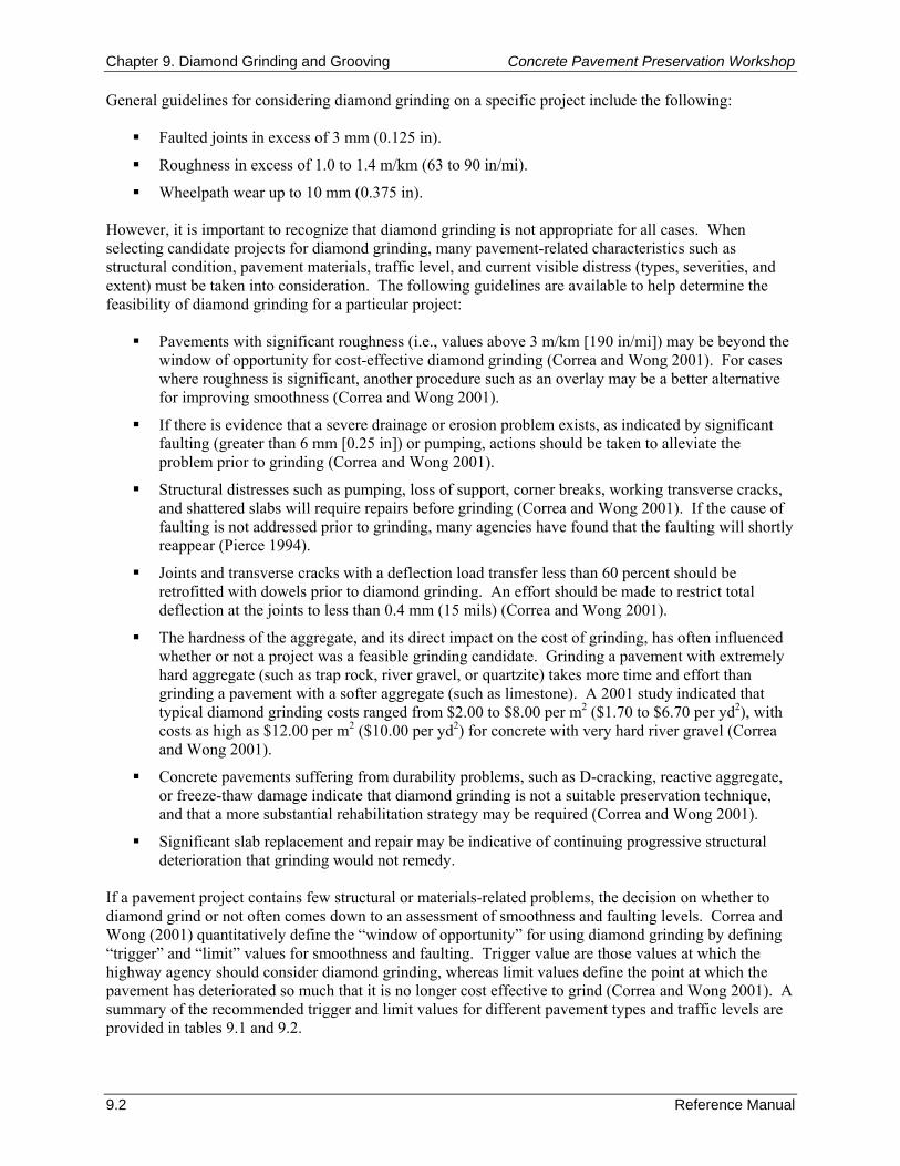
Chapter 9. Diamond Grinding and Grooving Concrete Pavement Preservation Workshop
9.2 Reference Manual
General guidelines for considering diamond grinding on a specific project include the following:
Faulted joints in excess of 3 mm (0.125 in).
Roughness in excess of 1.0 to 1.4 m/km (63 to 90 in/mi).
Wheelpath wear up to 10 mm (0.375 in). However, it is important to recognize that diamond grinding is not appropriate for all cases. When selecting candidate projects for diamond grinding, many pavement-related characteristics such as structural condition, pavement materials, traffic level, and current visible distress (types, severities, and extent) must be taken into consideration. The following guidelines are available to help determine the feasibility of diamond grinding for a particular project:
Pavements with significant roughness (i.e., values above 3 m/km [190 in/mi]) may be beyond the window of opportunity for cost-effective diamond grinding (Correa and Wong 2001). For cases where roughness is significant, another procedure such as an overlay may be a better alternative for improving smoothness (Correa and Wong 2001).
If there is evidence that a severe drainage or erosion problem exists, as indicated by significant faulting (greater than 6 mm [0.25 in]) or pumping, actions should be taken to alleviate the problem prior to grinding (Correa and Wong 2001).
Structural distresses such as pumping, loss of support, corner breaks, working transverse cracks, and shattered slabs will require repairs before grinding (Correa and Wong 2001). If the cause of faulting is not addressed prior to grinding, many agencies have found that the faulting will shortly reappear (Pierce 1994).
Joints and transverse cracks with a deflection load transfer less than 60 percent should be retrofitted with dowels prior to diamond grinding. An effort should be made to restrict total deflection at the joints to less than 0.4 mm (15 mils) (Correa and Wong 2001).
The hardness of the aggregate, and its direct impact on the cost of grinding, has often influenced whether or not a project was a feasible grinding candidate. Grinding a pavement with extremely hard aggregate (such as trap rock, river gravel, or quartzite) takes more time and effort than grinding a pavement with a softer aggregate (such as limestone). A 2001 study indicated that typical diamond grinding costs ranged from $2.00 to $8.00 per m2 ($1.70 to $6.70 per yd2), with costs as high as $12.00 per m2 ($10.00 per yd2) for concrete with very hard river gravel (Correa and Wong 2001).
Concrete pavements suffering from durability problems, such as D-cracking, reactive aggregate, or freeze-thaw damage indicate that diamond grinding is not a suitable preservation technique, and that a more substantial rehabilitation strategy may be required (Correa and Wong 2001).
Significant slab replacement and repair may be indicative of continuing progressive structural deterioration that grinding would not remedy.
If a pavement project contains few structural or materials-related problems, the decision on whether to diamond grind or not often comes down to an assessment of smoothness and faulting levels. Correa and Wong (2001) quantitatively define the “window of opportunity” for using diamond grinding by defining “trigger” and “limit” values for smoothness and faulting. Trigger value are those values at which the highway agency should consider diamond grinding, whereas limit values define the point at which the pavement has deteriorated so much that it is no longer cost effective to grind (Correa and Wong 2001). A summary of the recommended trigger and limit values for different pavement types and traffic levels are provided in tables 9.1 and 9.2.
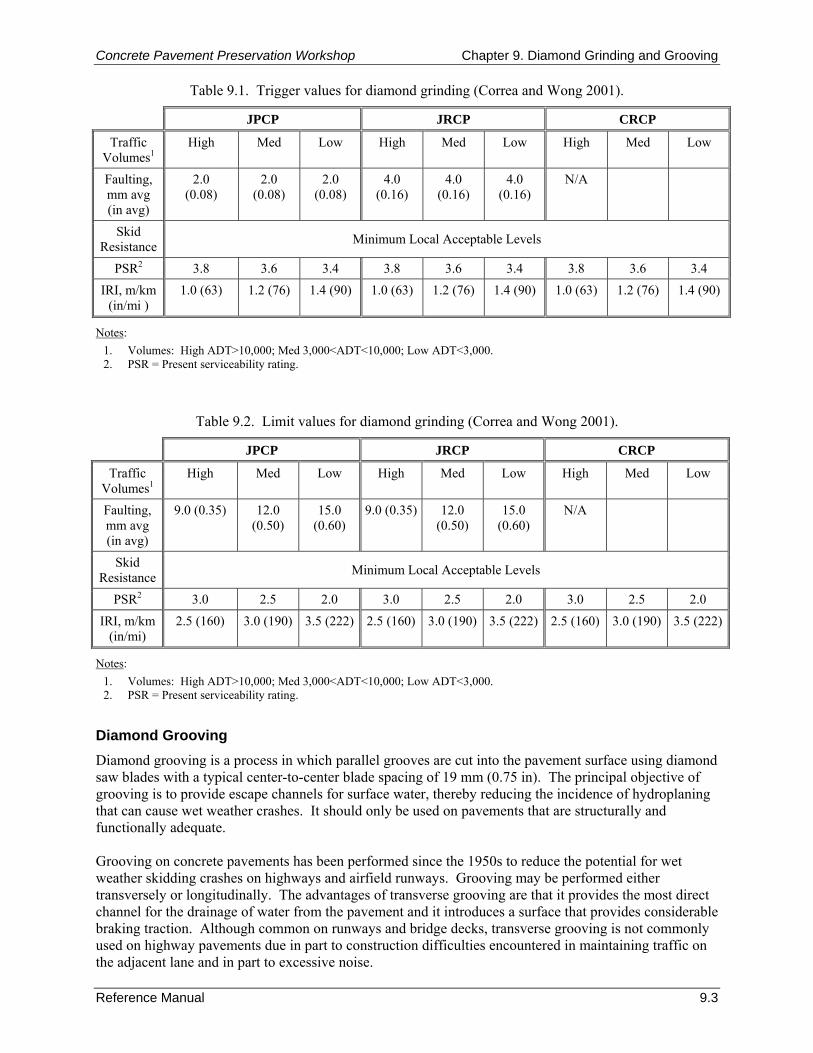
Concrete Pavement Preservation Workshop Chapter 9. Diamond Grinding and Grooving
Reference Manual 9.3
Table 9.1. Trigger values for diamond grinding (Correa and Wong 2001).
JPCP JRCP CRCP
Traffic Volumes1
High Med Low High Med Low High Med Low
Faulting, mm avg (in avg)
2.0 (0.08)
2.0 (0.08)
2.0 (0.08)
4.0 (0.16)
4.0 (0.16)
4.0 (0.16)
N/A
Skid Resistance Minimum Local Acceptable Levels
PSR2 3.8 3.6 3.4 3.8 3.6 3.4 3.8 3.6 3.4 IRI, m/km
(in/mi ) 1.0 (63) 1.2 (76) 1.4 (90) 1.0 (63) 1.2 (76) 1.4 (90) 1.0 (63) 1.2 (76) 1.4 (90)
Notes: 1. Volumes: High ADT>10,000; Med 3,000<ADT<10,000; Low ADT<3,000. 2. PSR = Present serviceability rating.
Table 9.2. Limit values for diamond grinding (Correa and Wong 2001).
JPCP JRCP CRCP
Traffic Volumes1
High Med Low High Med Low High Med Low
Faulting, mm avg (in avg)
9.0 (0.35) 12.0 (0.50)
15.0 (0.60)
9.0 (0.35) 12.0 (0.50)
15.0 (0.60)
N/A
Skid Resistance Minimum Local Acceptable Levels
PSR2 3.0 2.5 2.0 3.0 2.5 2.0 3.0 2.5 2.0 IRI, m/km
(in/mi) 2.5 (160) 3.0 (190) 3.5 (222) 2.5 (160) 3.0 (190) 3.5 (222) 2.5 (160) 3.0 (190) 3.5 (222)
Notes: 1. Volumes: High ADT>10,000; Med 3,000<ADT<10,000; Low ADT<3,000. 2. PSR = Present serviceability rating.
Diamond Grooving Diamond grooving is a process in which parallel grooves are cut into the pavement surface using diamond saw blades with a typical center-to-center blade spacing of 19 mm (0.75 in). The principal objective of grooving is to provide escape channels for surface water, thereby reducing the incidence of hydroplaning that can cause wet weather crashes. It should only be used on pavements that are structurally and functionally adequate. Grooving on concrete pavements has been performed since the 1950s to reduce the potential for wet weather skidding crashes on highways and airfield runways. Grooving may be performed either transversely or longitudinally. The advantages of transverse grooving are that it provides the most direct channel for the drainage of water from the pavement and it introduces a surface that provides considerable braking traction. Although common on runways and bridge decks, transverse grooving is not commonly used on highway pavements due in part to construction difficulties encountered in maintaining traffic on the adjacent lane and in part to excessive noise.
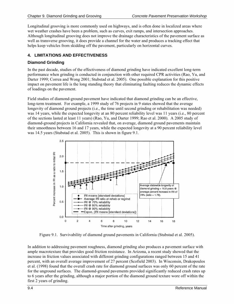
Chapter 9. Diamond Grinding and Grooving Concrete Pavement Preservation Workshop
9.4 Reference Manual
Longitudinal grooving is more commonly used on highways, and is often done in localized areas where wet weather crashes have been a problem, such as curves, exit ramps, and intersection approaches. Although longitudinal grooving does not improve the drainage characteristics of the pavement surface as well as transverse grooving, it does provide a channel for the water and produces a tracking effect that helps keep vehicles from skidding off the pavement, particularly on horizontal curves. 4. LIMITATIONS AND EFFECTIVENESS Diamond Grinding In the past decade, studies of the effectiveness of diamond grinding have indicated excellent long-term performance when grinding is conducted in conjunction with other required CPR activities (Rao, Yu, and Darter 1999; Correa and Wong 2001; Stubstad et al. 2005). One possible explanation for this positive impact on pavement life is the long standing theory that eliminating faulting reduces the dynamic effects of loadings on the pavement. Field studies of diamond-ground pavement have indicated that diamond grinding can be an effective, long-term treatment. For example, a 1999 study of 76 projects in 9 states showed that the average longevity of diamond ground projects (i.e., the time until second grinding or rehabilitation was needed) was 14 years, while the expected longevity at an 80 percent reliability level was 11 years (i.e., 80 percent of the sections lasted at least 11 years) (Rao, Yu, and Darter 1999; Rao et al. 2000). A 2005 study of diamond-ground projects in California revealed that, on average, diamond ground pavements maintain their smoothness between 16 and 17 years, while the expected longevity at a 90 percent reliability level was 14.5 years (Stubstad et al. 2005). This is shown in figure 9.1.
Figure 9.1. Survivability of diamond ground pavements in California (Stubstad et al. 2005).
In addition to addressing pavement roughness, diamond grinding also produces a pavement surface with ample macrotexture that provides good friction resistance. In Arizona, a recent study showed that the increase in friction values associated with different grinding configurations ranged between 15 and 41 percent, with an overall average improvement of 27 percent (Scofield 2003). In Wisconsin, Drakopoulos et al. (1998) found that the overall crash rate for diamond ground surfaces was only 60 percent of the rate for the unground surfaces. The diamond-ground pavements provided significantly reduced crash rates up to 6 years after the grinding, although a major portion of the diamond ground texture wore off within the first 2 years of grinding.
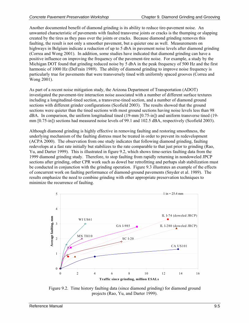
Concrete Pavement Preservation Workshop Chapter 9. Diamond Grinding and Grooving
Reference Manual 9.5
0
1
2
3
4
5
0 2 4 6 8 10 12 14 16
Traffic since grinding, million ESALs
Ave
rage
faul
ting,
mm
CA US101
GA I-985 IL I-280 (doweled JRCP)
IL I-74 (doweled JRCP)
MN TH10SC I-20
WI US61
Another documented benefit of diamond grinding is its ability to reduce tire-pavement noise. An unwanted characteristic of pavements with faulted transverse joints or cracks is the thumping or slapping created by the tires as they pass over the joints or cracks. Because diamond grinding removes this faulting, the result is not only a smoother pavement, but a quieter one as well. Measurements on highways in Belgium indicate a reduction of up to 5 dbA in pavement noise levels after diamond grinding (Correa and Wong 2001). In addition, some studies have indicated that diamond grinding can have a positive influence on improving the frequency of the pavement-tire noise. For example, a study by the Michigan DOT found that grinding reduced noise by 5 dbA in the peak frequency of 500 Hz and the first harmonic of 1000 Hz (DeFrain 1989). The ability of diamond grinding to improve noise frequency is particularly true for pavements that were transversely tined with uniformly spaced grooves (Correa and Wong 2001). As part of a recent noise mitigation study, the Arizona Department of Transportation (ADOT) investigated the pavement-tire interaction noise associated with a number of different surface textures including a longitudinal-tined section, a transverse-tined section, and a number of diamond ground sections with different grinder configurations (Scofield 2003). The results showed that the ground sections were quieter than the tined sections with most ground sections having noise levels less than 98 dBA. In comparison, the uniform longitudinal tined (19-mm [0.75-in]) and uniform transverse tined (19-mm [0.75-in]) sections had measured noise levels of 99.1 and 102.5 dBA, respectively (Scofield 2003). Although diamond grinding is highly effective in removing faulting and restoring smoothness, the underlying mechanism of the faulting distress must be treated in order to prevent its redevelopment (ACPA 2000). The observation from one study indicates that following diamond grinding, faulting redevelops at a fast rate initially but stabilizes to the rate comparable to that just prior to grinding (Rao, Yu, and Darter 1999). This is illustrated in figure 9.2, which shows time-series faulting data from the 1999 diamond grinding study. Therefore, to stop faulting from rapidly returning in nondoweled JPCP sections after grinding, other CPR work such as dowel bar retrofitting and perhaps slab stabilization must be conducted in conjunction with the grinding operation. Figure 9.3 illustrates an example of the effects of concurrent work on faulting performance of diamond-ground pavements (Snyder et al. 1989). The results emphasize the need to combine grinding with other appropriate preservation techniques to minimize the recurrence of faulting.
Figure 9.2. Time history faulting data (since diamond grinding) for diamond ground projects (Rao, Yu, and Darter 1999).
1 in = 25.4 mm
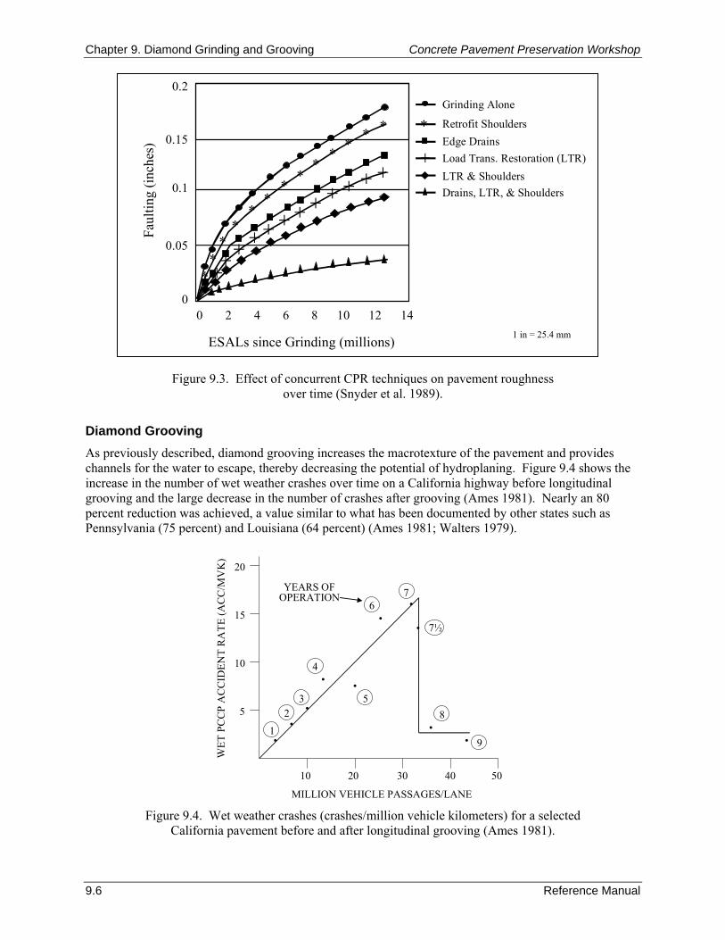
Chapter 9. Diamond Grinding and Grooving Concrete Pavement Preservation Workshop
9.6 Reference Manual
Faul
ting
(inch
es)
Drains, LTR, & Shoulders
Edge Drains
Grinding Alone
LTR & ShouldersLoad Trans. Restoration (LTR)+
0.2
0.15
0.1
0.05
0
ESALs since Grinding (millions)
0 2 4 6 8 10 12 14
∗
∗∗∗∗
∗∗
∗∗∗
∗∗
∗
++++++++++++
Retrofit Shoulders∗
Figure 9.3. Effect of concurrent CPR techniques on pavement roughness
over time (Snyder et al. 1989).
Diamond Grooving As previously described, diamond grooving increases the macrotexture of the pavement and provides channels for the water to escape, thereby decreasing the potential of hydroplaning. Figure 9.4 shows the increase in the number of wet weather crashes over time on a California highway before longitudinal grooving and the large decrease in the number of crashes after grooving (Ames 1981). Nearly an 80 percent reduction was achieved, a value similar to what has been documented by other states such as Pennsylvania (75 percent) and Louisiana (64 percent) (Ames 1981; Walters 1979).
10 20 30 40 50
5
10
15
20
•
•
•
•
2
•
••
1
3
4
6
•5
7
7½
8
9
•
•YEARS OF
OPERATION
MILLION VEHICLE PASSAGES/LANE
WET
PC
CP
AC
CID
ENT
RA
TE (A
CC
/MV
K)
Figure 9.4. Wet weather crashes (crashes/million vehicle kilometers) for a selected
California pavement before and after longitudinal grooving (Ames 1981).
1 in = 25.4 mm
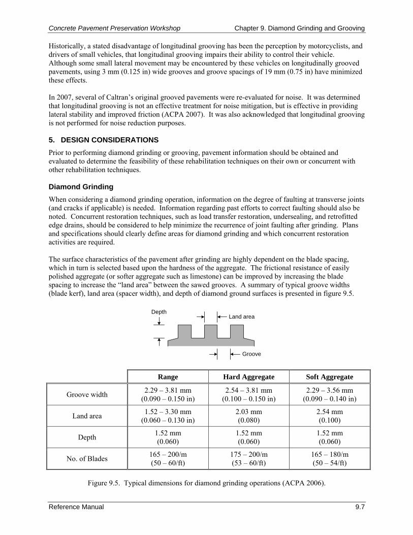
Concrete Pavement Preservation Workshop Chapter 9. Diamond Grinding and Grooving
Reference Manual 9.7
Historically, a stated disadvantage of longitudinal grooving has been the perception by motorcyclists, and drivers of small vehicles, that longitudinal grooving impairs their ability to control their vehicle. Although some small lateral movement may be encountered by these vehicles on longitudinally grooved pavements, using 3 mm (0.125 in) wide grooves and groove spacings of 19 mm (0.75 in) have minimized these effects. In 2007, several of Caltran’s original grooved pavements were re-evaluated for noise. It was determined that longitudinal grooving is not an effective treatment for noise mitigation, but is effective in providing lateral stability and improved friction (ACPA 2007). It was also acknowledged that longitudinal grooving is not performed for noise reduction purposes. 5. DESIGN CONSIDERATIONS Prior to performing diamond grinding or grooving, pavement information should be obtained and evaluated to determine the feasibility of these rehabilitation techniques on their own or concurrent with other rehabilitation techniques. Diamond Grinding When considering a diamond grinding operation, information on the degree of faulting at transverse joints (and cracks if applicable) is needed. Information regarding past efforts to correct faulting should also be noted. Concurrent restoration techniques, such as load transfer restoration, undersealing, and retrofitted edge drains, should be considered to help minimize the recurrence of joint faulting after grinding. Plans and specifications should clearly define areas for diamond grinding and which concurrent restoration activities are required. The surface characteristics of the pavement after grinding are highly dependent on the blade spacing, which in turn is selected based upon the hardness of the aggregate. The frictional resistance of easily polished aggregate (or softer aggregate such as limestone) can be improved by increasing the blade spacing to increase the “land area” between the sawed grooves. A summary of typical groove widths (blade kerf), land area (spacer width), and depth of diamond ground surfaces is presented in figure 9.5.
DepthLand area
Groove
Range Hard Aggregate Soft Aggregate
Groove width 2.29 – 3.81 mm (0.090 – 0.150 in)
2.54 – 3.81 mm (0.100 – 0.150 in)
2.29 – 3.56 mm (0.090 – 0.140 in)
Land area 1.52 – 3.30 mm (0.060 – 0.130 in)
2.03 mm (0.080)
2.54 mm (0.100)
Depth 1.52 mm (0.060)
1.52 mm (0.060)
1.52 mm (0.060)
No. of Blades 165 – 200/m (50 – 60/ft)
175 – 200/m (53 – 60/ft)
165 – 180/m (50 – 54/ft)
Figure 9.5. Typical dimensions for diamond grinding operations (ACPA 2006).
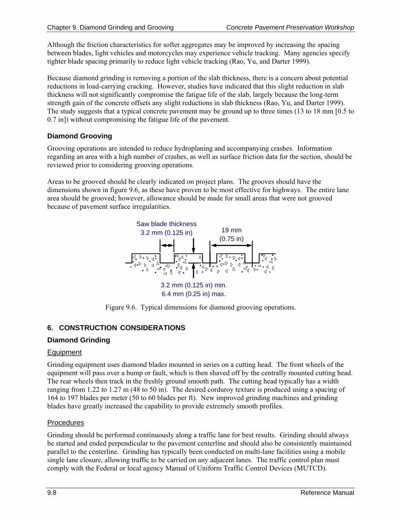
Chapter 9. Diamond Grinding and Grooving Concrete Pavement Preservation Workshop
9.8 Reference Manual
Although the friction characteristics for softer aggregates may be improved by increasing the spacing between blades, light vehicles and motorcycles may experience vehicle tracking. Many agencies specify tighter blade spacing primarily to reduce light vehicle tracking (Rao, Yu, and Darter 1999). Because diamond grinding is removing a portion of the slab thickness, there is a concern about potential reductions in load-carrying cracking. However, studies have indicated that this slight reduction in slab thickness will not significantly compromise the fatigue life of the slab, largely because the long-term strength gain of the concrete offsets any slight reductions in slab thickness (Rao, Yu, and Darter 1999). The study suggests that a typical concrete pavement may be ground up to three times (13 to 18 mm [0.5 to 0.7 in]) without compromising the fatigue life of the pavement. Diamond Grooving Grooving operations are intended to reduce hydroplaning and accompanying crashes. Information regarding an area with a high number of crashes, as well as surface friction data for the section, should be reviewed prior to considering grooving operations. Areas to be grooved should be clearly indicated on project plans. The grooves should have the dimensions shown in figure 9.6, as these have proven to be most effective for highways. The entire lane area should be grooved; however, allowance should be made for small areas that were not grooved because of pavement surface irregularities.
Saw blade thickness3.2 mm (0.125 in)
3.2 mm (0.125 in) min.6.4 mm (0.25 in) max.
19 mm(0.75 in)
Figure 9.6. Typical dimensions for diamond grooving operations.
6. CONSTRUCTION CONSIDERATIONS Diamond Grinding Equipment
Grinding equipment uses diamond blades mounted in series on a cutting head. The front wheels of the equipment will pass over a bump or fault, which is then shaved off by the centrally mounted cutting head. The rear wheels then track in the freshly ground smooth path. The cutting head typically has a width ranging from 1.22 to 1.27 m (48 to 50 in). The desired corduroy texture is produced using a spacing of 164 to 197 blades per meter (50 to 60 blades per ft). New improved grinding machines and grinding blades have greatly increased the capability to provide extremely smooth profiles. Procedures
Grinding should be performed continuously along a traffic lane for best results. Grinding should always be started and ended perpendicular to the pavement centerline and should also be consistently maintained parallel to the centerline. Grinding has typically been conducted on multi-lane facilities using a mobile single lane closure, allowing traffic to be carried on any adjacent lanes. The traffic control plan must comply with the Federal or local agency Manual of Uniform Traffic Control Devices (MUTCD).
Concrete Pavement Preservation Workshop Chapter 9. Diamond Grinding and Grooving
Reference Manual 9.9
Grinding equipment should have a long reference beam so the existing pavement can be used as a reference. By blending the highs and lows, excellent riding quality can be obtained with a minimum depth of removal. Low spots will likely be encountered, and specifications should recognize this. Generally, it is required that a minimum of 95 percent of the area within any 1 m by 30 m (3 ft by 100 ft) test area be textured by the grinding operation. Isolated low spots of less than 0.2 m2 (2 ft2) should not require texturing if lowering the cutting head would be required (ACPA 2000). Because of the relatively narrow width of the cutting head, more than a single pass of the grinding equipment will be required. It is recommended that the maximum overlap between adjacent passes be 50 mm (2 in). Some projects use multiple grinding machines working together to expedite grinding operations. Diamond Grooving Equipment
Equipment used to groove pavements is specifically designed for this task. Because fewer diamond blades are required on the cutting head, the head width can be substantially greater than that used in diamond grinding. Some equipment are available that have grinding head width of 1.8 m (6 ft) or more. The diamond blades are spaced to increase the “land area” between grooves, as illustrated in figure 9.6. Typically, the blades are spaced 19 mm (0.75 in) apart for longitudinal grooving, and the grooves have a width between 2.5 and 3 mm (0.1 and 0.125 in), and are cut to a depth of 3 to 6 mm (0.125 to 0.25 in). For transverse grooving, random grooves spaced 10 to 40 mm (0.4 to 1.6 in) apart and 3 mm (0.125 in) wide are recommended to reduce tire noise (Hibbs and Larson 1996). Procedures
As previously indicated, grooving is most commonly performed longitudinally along the pavement. Typically, only localized areas (such as curves or intersection approaches) are grooved, instead of the entire project length. However, surface friction and wet weather crash data can be used to determine the extent of the grooving that may be needed. Procedures typically follow those described previously for diamond grinding. The traffic control plan must comply with Federal or local agency MUTCD standards to ensure the safety of the construction personnel and traveling public. Slurry Removal The grinding and grooving operation produces a slurry consisting of ground concrete and the water used to cool the blades. This slurry is picked up by on-board wet-vacuums, and must be disposed of in accordance with local environmental regulations. 7. QUALITY CONTROL As with any pavement project, the performance of LTR projects is greatly dependent on the quality of the construction procedures. Paying close attention to the procedures during construction greatly increases the chances of obtaining a surface with desired characteristics at the end of the project. The remainder of this section summarizes the recommended quality control activities for diamond grinding as presented in FHWA’s Diamond Grinding of Portland Cement Concrete Pavements Checklist (FHWA 2005). Although this list of activities in this checklist is specific to the diamond grinding process, many of the same activities can easily be applied to the diamond grooving process.

Chapter 9. Diamond Grinding and Grooving Concrete Pavement Preservation Workshop
9.10 Reference Manual
Preliminary Responsibilities Prior to the start of construction procedures, the agency should review of pertinent project-related documents, the project’s current condition, and materials to be used on the project. The following specific lists of items are provided as a model QC checklist for these preliminary items. Document Review
All of the following documents should be reviewed prior to the start of any construction activities. Any suspected problems should be identified and reconciled as part of the preliminary review process.
Bid/project specifications and design.
Special provisions.
Agency application requirements.
Traffic control plan.
Equipment specifications.
Manufacturer’s instructions.
Material safety data sheets (MSDS) (if required for concrete slurry). Project Review
An updated review of the pavement condition is warranted to ensure that the project is still a viable candidate for diamond grinding. The following should be evaluated as part of the review process:
Verify that the pavement conditions have not significantly changed since the project was designed.
Assess the overall condition of the joints and cracks. Joints and transverse cracks exhibiting severe faulting (equal to or greater than 12 mm [0.5 in]) or displaying evidence of pumping (e.g., surface staining or isolated wetness) are potential candidates for load transfer restoration with dowels prior to diamond grinding.
Verify that structural repairs are completed in the proper sequence (i.e., full-depth repairs, partial-depth repairs, load-transfer restoration, diamond grinding, and joint resealing).
Equipment Inspections
Prior to beginning construction, all construction equipment must be examined. The following are equipment-related items that should be checked:
Verify that the diamond grinding machine meets requirements of the contract documents for weight, horsepower, and configuration.
Verify that the blade spacing on the diamond-grinding cutting head meets the requirements of the contract documents.
Verify that the vacuum assembly is in good working order and capable of removing concrete slurry from the pavement surface.
Verify that the profilograph or pavement profiler meets requirements of the contract documents.
Verify that the unit has been calibrated in accordance with manufacturer’s recommendations and contract documents.
Verify that the profilograph operator meets the requirements of the contract documents for training/certification.
Concrete Pavement Preservation Workshop Chapter 9. Diamond Grinding and Grooving
Reference Manual 9.11
Project Inspection Responsibilities During the construction process, an inspector should verify that:
Diamond grinding proceeds in a direction parallel with the pavement centerline, beginning and ending lines normal to the pavement centerline.
Diamond-grinding results in a corduroy texture extending across the full lane width and complying with contract documents.
Texturing cut into the existing pavement surface is in accordance with texturing requirements presented in the contract documents. Although typical values were presented in figure 9.5, specific dimensions and tolerances contained in the project documents take precedence.
Each application of the diamond-ground texture overlaps the previous application by no more than the amount designated in the contract documents, typically 50 mm (2 in).
Each application of the diamond-ground texture does not exceed the depth of the previous application by more than the specified amount (typically 6 mm [0.25 in]).
The transverse slope of the ground surface is uniform to the extent that no misalignments or depressions that are capable of ponding water exist. Project documents typically have specific measurable criteria for transverse slope that must be met.
The diamond-ground texture meets smoothness specifications (check on a daily basis).
The concrete slurry is adequately vacuumed from the pavement surface and is not allowed to flow into adjacent traffic lanes.
The grinding residue is not discharged into a waterway, a roadway slope within 61 m (200 ft) of a waterway, or any area forbidden by the contract documents or engineer. Concrete slurry from the grinding operation is typically collected and discharged at a disposal area designated in the contract document.
Weather Requirements The following weather-related items should be checked immediately prior to construction:
Air and/or surface temperature should meet minimum agency requirements (typically 2 °C [35 °F] and above) for diamond grinding operations in accordance with contract documents.
Diamond grinding shall not proceed if icy weather conditions are imminent. Traffic Control To manage the flow of traffic through the work zone, the following traffic-related items should be checked or verified:
Verify that the signs and devices used match the traffic control plan presented in the contract documents.
Verify that the set-up complies with the Federal or local agency Manual on Uniform Traffic Control Devices (MUTCD) or local agency procedures.
Verify that the repaired pavement is not opened to traffic until all equipment and personnel have been removed from the work zone.
Verify that signs are removed or covered when they are no longer needed.
Verify that unsafe conditions, if any, are reported to a supervisor (contractor or agency).
Chapter 9. Diamond Grinding and Grooving Concrete Pavement Preservation Workshop
9.12 Reference Manual
8. TROUBLESHOOTING Potential construction problems associated with diamond grinding and diamond grooving that may be encountered are presented in tables 9.3 and 9.4, respectively. Typical causes and recommended solutions are also provided in these tables. 9. SUMMARY Diamond grinding and grooving are surface restoration techniques that have been used successfully to correct a variety of surface distresses on concrete pavements. The appropriate application of these techniques can result in a cost-effective extension of pavement life. Diamond grinding uses closely spaced, diamond saw blades to remove a thin layer of material from a concrete pavement surface. Although it is primarily used to restore or improve ride quality by removing transverse joint faulting and other surface irregularities, other common usages of diamond grinding include improving skid resistance (increasing macrotexture) and reducing tire-pavement interaction noise. Grooving is the use of diamond saw blades to cut longitudinal or transverse grooves into a pavement surface. The purpose of grooving is to provide channels on the pavement that collect water and drain if from the surface. A reduction in surface water translates into a reduction in the potential for wet weather crashes associated with hydroplaning and splash and spray. Longitudinal grooving is commonly employed along local areas such as curves, where the grooves provide a tracking effect that helps hold vehicles on the road. For areas where increased braking resistance is required, transverse grooving is often used. Grooving is usually done on pavements that show little or no structural distress. 10. REFERENCES American Concrete Pavement Association (ACPA). 2000. Diamond Grinding and Concrete Pavement Restoration. TB-008.01P. American Concrete Pavement Association, Skokie, IL.
American Concrete Pavement Association (ACPA). 2006. Concrete Pavement Field Reference - Preservation and Repair. Report EB239P. American Concrete Pavement Association, Skokie, IL.
American Concrete Pavement Association (ACPA). 2007. Caltrans Diamond Grooving Experiment—38 Years Later. R&T Update 8.03. American Concrete Pavement Association, Skokie, IL.
Ames, W. H. 1981. “Profile Correction and Surface Retexturing.” Proceedings of the National Seminar on PCC Pavement Recycling and Rehabilitation. FHWA-TS-82-208. Federal Highway Administration, Washington, DC.
Correa, A. L. and B. Wong. 2001. Concrete Pavement Rehabilitation—Guide for Diamond Grinding. FHWA-SRC-1/10-01(5M). Federal Highway Administration, Washington, DC.
Defrain, L. 1989. Noise Analysis of Ground Surface on I-69 WB Near Lowell Road C.S. 19043. Technical Memorandum, Research Project 88 TI-1342. Michigan Department of Transportation, Lansing, MI.
Drakopoulos, A., T. H. Wenzel, S. F. Shober, and R. B. Schmiedlin. 1998. “Crash Experience on Tined and Continuously Ground Portland Cement Concrete Pavements.” Transportation Research Record 1639. Transportation Research Board, Washington, DC.
Federal Highway Administration (FHWA). 2005. Pavement Preservation Checklist Series #7: Diamond Grinding of Portland Cement Concrete Pavements. FHWA-IF-03040. Federal Highway Administration, Washington, DC.
Hibbs, B., and R. Larson. 1996. Report of the PCC Surface Texturing Technical Working Group. FHWA-SA-96-068. Federal Highway Administration, Washington, DC.
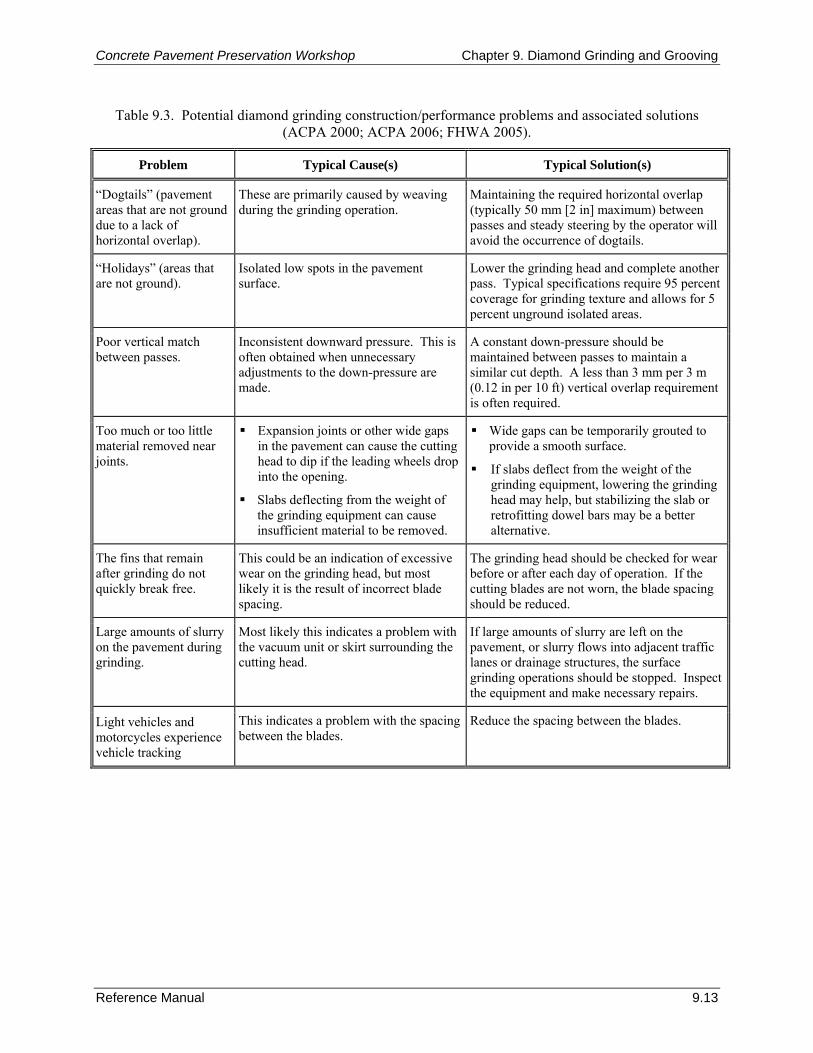
Concrete Pavement Preservation Workshop Chapter 9. Diamond Grinding and Grooving
Reference Manual 9.13
Table 9.3. Potential diamond grinding construction/performance problems and associated solutions (ACPA 2000; ACPA 2006; FHWA 2005).
Problem Typical Cause(s) Typical Solution(s)
“Dogtails” (pavement areas that are not ground due to a lack of horizontal overlap).
These are primarily caused by weaving during the grinding operation.
Maintaining the required horizontal overlap (typically 50 mm [2 in] maximum) between passes and steady steering by the operator will avoid the occurrence of dogtails.
“Holidays” (areas that are not ground).
Isolated low spots in the pavement surface.
Lower the grinding head and complete another pass. Typical specifications require 95 percent coverage for grinding texture and allows for 5 percent unground isolated areas.
Poor vertical match between passes.
Inconsistent downward pressure. This is often obtained when unnecessary adjustments to the down-pressure are made.
A constant down-pressure should be maintained between passes to maintain a similar cut depth. A less than 3 mm per 3 m (0.12 in per 10 ft) vertical overlap requirement is often required.
Too much or too little material removed near joints.
Expansion joints or other wide gaps in the pavement can cause the cutting head to dip if the leading wheels drop into the opening.
Slabs deflecting from the weight of the grinding equipment can cause insufficient material to be removed.
Wide gaps can be temporarily grouted to provide a smooth surface.
If slabs deflect from the weight of the grinding equipment, lowering the grinding head may help, but stabilizing the slab or retrofitting dowel bars may be a better alternative.
The fins that remain after grinding do not quickly break free.
This could be an indication of excessive wear on the grinding head, but most likely it is the result of incorrect blade spacing.
The grinding head should be checked for wear before or after each day of operation. If the cutting blades are not worn, the blade spacing should be reduced.
Large amounts of slurry on the pavement during grinding.
Most likely this indicates a problem with the vacuum unit or skirt surrounding the cutting head.
If large amounts of slurry are left on the pavement, or slurry flows into adjacent traffic lanes or drainage structures, the surface grinding operations should be stopped. Inspect the equipment and make necessary repairs.
Light vehicles and motorcycles experience vehicle tracking
This indicates a problem with the spacing between the blades.
Reduce the spacing between the blades.
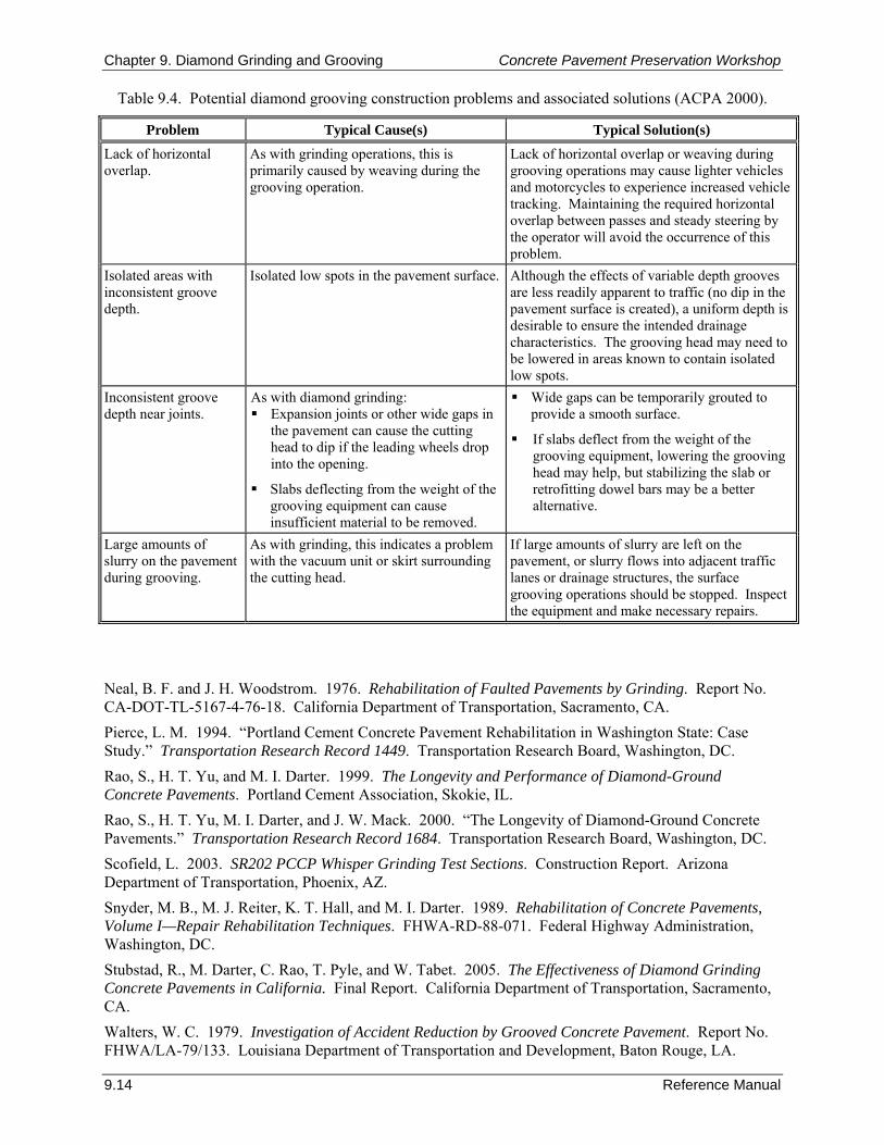
Chapter 9. Diamond Grinding and Grooving Concrete Pavement Preservation Workshop
9.14 Reference Manual
Table 9.4. Potential diamond grooving construction problems and associated solutions (ACPA 2000).
Problem Typical Cause(s) Typical Solution(s)
Lack of horizontal overlap.
As with grinding operations, this is primarily caused by weaving during the grooving operation.
Lack of horizontal overlap or weaving during grooving operations may cause lighter vehicles and motorcycles to experience increased vehicle tracking. Maintaining the required horizontal overlap between passes and steady steering by the operator will avoid the occurrence of this problem.
Isolated areas with inconsistent groove depth.
Isolated low spots in the pavement surface. Although the effects of variable depth grooves are less readily apparent to traffic (no dip in the pavement surface is created), a uniform depth is desirable to ensure the intended drainage characteristics. The grooving head may need to be lowered in areas known to contain isolated low spots.
Inconsistent groove depth near joints.
As with diamond grinding: Expansion joints or other wide gaps in
the pavement can cause the cutting head to dip if the leading wheels drop into the opening.
Slabs deflecting from the weight of the grooving equipment can cause insufficient material to be removed.
Wide gaps can be temporarily grouted to provide a smooth surface.
If slabs deflect from the weight of the grooving equipment, lowering the grooving head may help, but stabilizing the slab or retrofitting dowel bars may be a better alternative.
Large amounts of slurry on the pavement during grooving.
As with grinding, this indicates a problem with the vacuum unit or skirt surrounding the cutting head.
If large amounts of slurry are left on the pavement, or slurry flows into adjacent traffic lanes or drainage structures, the surface grooving operations should be stopped. Inspect the equipment and make necessary repairs.
Neal, B. F. and J. H. Woodstrom. 1976. Rehabilitation of Faulted Pavements by Grinding. Report No. CA-DOT-TL-5167-4-76-18. California Department of Transportation, Sacramento, CA. Pierce, L. M. 1994. “Portland Cement Concrete Pavement Rehabilitation in Washington State: Case Study.” Transportation Research Record 1449. Transportation Research Board, Washington, DC. Rao, S., H. T. Yu, and M. I. Darter. 1999. The Longevity and Performance of Diamond-Ground Concrete Pavements. Portland Cement Association, Skokie, IL. Rao, S., H. T. Yu, M. I. Darter, and J. W. Mack. 2000. “The Longevity of Diamond-Ground Concrete Pavements.” Transportation Research Record 1684. Transportation Research Board, Washington, DC. Scofield, L. 2003. SR202 PCCP Whisper Grinding Test Sections. Construction Report. Arizona Department of Transportation, Phoenix, AZ. Snyder, M. B., M. J. Reiter, K. T. Hall, and M. I. Darter. 1989. Rehabilitation of Concrete Pavements, Volume I—Repair Rehabilitation Techniques. FHWA-RD-88-071. Federal Highway Administration, Washington, DC. Stubstad, R., M. Darter, C. Rao, T. Pyle, and W. Tabet. 2005. The Effectiveness of Diamond Grinding Concrete Pavements in California. Final Report. California Department of Transportation, Sacramento, CA. Walters, W. C. 1979. Investigation of Accident Reduction by Grooved Concrete Pavement. Report No. FHWA/LA-79/133. Louisiana Department of Transportation and Development, Baton Rouge, LA.
Concrete Pavement Preservation Workshop Chapter 10. Joint Resealing
Reference Manual 10.1
CHAPTER 10. JOINT RESEALING AND CRACK SEALING 1. LEARNING OUTCOMES This chapter describes recommended procedures for both joint resealing and crack sealing operations on concrete pavements. Upon successful completion of this chapter, the participants will be able to accomplish the following:
1. List the benefits of joint resealing and crack sealing.
2. List the desirable sealant properties and characteristics.
3. Describe recommended installation procedures.
4. Identify typical construction problems and appropriate remedies. 2. INTRODUCTION Joint and crack sealing is a commonly performed pavement maintenance activity that serves two primary purposes. One purpose is to reduce the amount of moisture that can infiltrate a pavement structure, thereby reducing moisture-related distresses such as pumping, joint faulting, base and subbase erosion, and corner breaks. The other is to prevent the intrusion of incompressible materials so that pressure-related distresses such as spalling, blowups, buckling, and slab shattering are prevented. Previous studies have indicated that sealant materials became ineffective anywhere from 1 to 4 years after placement (Peterson 1982; PIARC 1992). However, recent improvements in sealant materials, an increased recognition of the importance of a proper reservoir design, and an emphasis on effective joint preparation procedures have been found to increase the expected life of sealant installations (Smith et al. 1991; Smith et al. 1999). Although joint sealing continues to be a widely used maintenance technique, there remains a persistent controversy over whether joint sealing is needed for new concrete pavement construction (Shober 1986; Shober 1997; McGhee 1995; Hall and Crovetti 2000). Nevertheless, the general recommendation is that if the pavement was sealed originally, then it should continue to be resealed at appropriate intervals. This chapter presents detailed discussions on the appropriate use and recommended installation procedures for joint resealing and crack sealing operations. It also provides information QC procedures, and troubleshooting. The focus is on “sealing” operations, in which the joint or crack is carefully prepared and a high-quality sealant material is installed. 3. PURPOSE AND PROJECT SELECTION As previously described, free water entering joints or cracks can accumulate beneath the slab, contributing to distresses such as pumping, loss of support, faulting, and corner breaks. In addition, incompressibles that infiltrate poorly sealed joints or cracks interfere with normal opening and closing movements, causing compressive stresses in the slab and increasing the potential for spalling. If the compressive stresses exceed the compressive strength of the deteriorated pavement, blowups or buckling may occur. Even if blowups do not occur, continual intrusion of incompressibles may cause the pavement to “grow.” This growth can force movement of nearby bridge abutments or other pavement structures that may, over time, cause serious damage and necessitate major rehabilitation. Sealing operations in concrete pavements may be performed at both joints and cracks to minimize water ingress and to prevent the infiltration of incompressibles. Most joint sealing and resealing operations focus on the transverse joints, although the longitudinal joints (lane-shoulder or lane-lane) are generally sealed at the same time.
Chapter 10. Joint Resealing Concrete Pavement Preservation Workshop
10.2 Reference Manual
Application of Joint Resealing Joint resealing should be performed when the existing sealant material is no longer performing its intended function. This is indicated by missing sealant, sealant that is in place but not bonded to the joint faces, or sealed joints that contain incompressibles. Some agencies specify that joints be resealed when a certain amount of sealant material (typically 25 to 50 percent) has failed, whereas other agencies base their decision on pavement type, pavement and sealant condition, and available funding (Evans, Smith, and Romine 1999). The optimum time of the year to perform joint resealing is in the spring or the fall when moderate installation temperatures are prevalent. The greatest benefits from resealing are expected when the pavement is not severely deteriorated and when joint resealing is performed in conjunction with other pavement restoration activities, such as full-depth repair, partial-depth repair, and diamond grinding. Application of Crack Sealing Crack sealing is a comprehensive operation involving thorough crack preparation and placement of high-quality materials into or over candidate cracks to significantly reduce moisture infiltration and to retard the rate of crack deterioration. Crack sealing is most effective when performed on concrete pavements that exhibit minimal structural deterioration and when the cracks are relatively narrow with minimal spalling. Crack sealing may, however, be used on random transverse and longitudinal cracks of low- or medium-severity where the crack width is 13 mm (0.5 in) or less (ACPA 1995). Full-depth working transverse cracks typically experience the same range of movement as transverse joints; therefore, it is recommended that these cracks be sealed to reduce the potential of water and incompressible infiltration; an alternative to sealing of full-depth working cracks is load transfer restoration (ACPA 1995). 4. MATERIAL SELECTION When planning a joint resealing project, one of the primary design activities is the selection of an appropriate sealant material. Material selection is dependent on a number of factors, including:
Climate conditions (at time of installation and during the life of the sealant).
Traffic level and percent trucks.
Crack characteristics and density.
Material availability and cost.
Contractor experience.
Safety concerns. The remainder of this section discusses material selection considerations for a given sealing project. Specifically, this section introduces the different types of sealant materials that are typically used on concrete pavement sealing projects, introduces some of the more critical performance-related material properties, and discusses cost considerations that may impact the selection of the sealant material. Available Material Types Joint resealing and crack sealing operations generally employ either hot-applied thermoplastic materials or cold-applied thermosetting sealant materials. Table 10.1 lists some of the hot- and cold-applied materials available for sealing joints and cracks in concrete pavements (ACPA 2006). Details of the different material type categories typically used for joint resealing or crack sealing projects are described below. Note that although preformed sealant types are included in table 10.1, preformed neoprene compression seals are recommended for use only in new pavements (ACPA 2006).
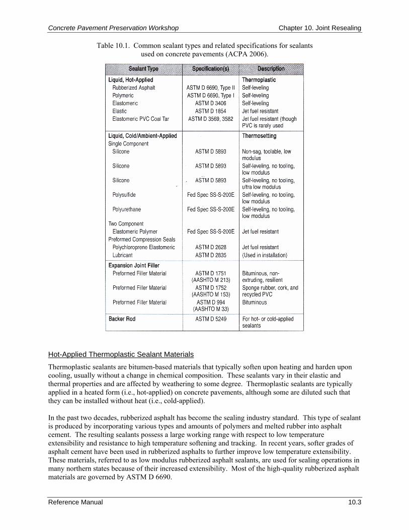
Concrete Pavement Preservation Workshop Chapter 10. Joint Resealing
Reference Manual 10.3
Table 10.1. Common sealant types and related specifications for sealants used on concrete pavements (ACPA 2006).
Hot-Applied Thermoplastic Sealant Materials
Thermoplastic sealants are bitumen-based materials that typically soften upon heating and harden upon cooling, usually without a change in chemical composition. These sealants vary in their elastic and thermal properties and are affected by weathering to some degree. Thermoplastic sealants are typically applied in a heated form (i.e., hot-applied) on concrete pavements, although some are diluted such that they can be installed without heat (i.e., cold-applied). In the past two decades, rubberized asphalt has become the sealing industry standard. This type of sealant is produced by incorporating various types and amounts of polymers and melted rubber into asphalt cement. The resulting sealants possess a large working range with respect to low temperature extensibility and resistance to high temperature softening and tracking. In recent years, softer grades of asphalt cement have been used in rubberized asphalts to further improve low temperature extensibility. These materials, referred to as low modulus rubberized asphalt sealants, are used for sealing operations in many northern states because of their increased extensibility. Most of the high-quality rubberized asphalt materials are governed by ASTM D 6690.
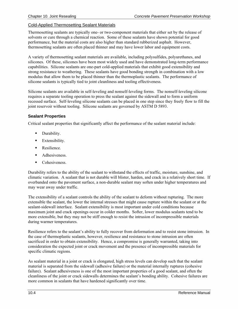
Chapter 10. Joint Resealing Concrete Pavement Preservation Workshop
10.4 Reference Manual
Cold-Applied Thermosetting Sealant Materials
Thermosetting sealants are typically one- or two-component materials that either set by the release of solvents or cure through a chemical reaction. Some of these sealants have shown potential for good performance, but the material costs are also higher than standard rubberized asphalt. However, thermosetting sealants are often placed thinner and may have lower labor and equipment costs. A variety of thermosetting sealant materials are available, including polysulfides, polyurethanes, and silicones. Of these, silicones have been most widely used and have demonstrated long-term performance capabilities. Silicone sealants are one-part cold-applied materials that exhibit good extensibility and strong resistance to weathering. These sealants have good bonding strength in combination with a low modulus that allow them to be placed thinner than the thermoplastic sealants. The performance of silicone sealants is typically tied to joint cleanliness and tooling effectiveness. Silicone sealants are available in self-leveling and nonself-leveling forms. The nonself-leveling silicone requires a separate tooling operation to press the sealant against the sidewall and to form a uniform recessed surface. Self-leveling silicone sealants can be placed in one step since they freely flow to fill the joint reservoir without tooling. Silicone sealants are governed by ASTM D 5893. Sealant Properties Critical sealant properties that significantly affect the performance of the sealant material include:
Durability.
Extensibility.
Resilience.
Adhesiveness.
Cohesiveness. Durability refers to the ability of the sealant to withstand the effects of traffic, moisture, sunshine, and climatic variation. A sealant that is not durable will blister, harden, and crack in a relatively short time. If overbanded onto the pavement surface, a non-durable sealant may soften under higher temperatures and may wear away under traffic. The extensibility of a sealant controls the ability of the sealant to deform without rupturing. The more extensible the sealant, the lower the internal stresses that might cause rupture within the sealant or at the sealant-sidewall interface. Sealant extensibility is most important under cold conditions because maximum joint and crack openings occur in colder months. Softer, lower modulus sealants tend to be more extensible, but they may not be stiff enough to resist the intrusion of incompressible materials during warmer temperatures. Resilience refers to the sealant’s ability to fully recover from deformation and to resist stone intrusion. In the case of thermoplastic sealants, however, resilience and resistance to stone intrusion are often sacrificed in order to obtain extensibility. Hence, a compromise is generally warranted, taking into consideration the expected joint or crack movement and the presence of incompressible materials for specific climatic regions. As sealant material in a joint or crack is elongated, high stress levels can develop such that the sealant material is separated from the sidewall (adhesive failure) or the material internally ruptures (cohesive failure). Sealant adhesiveness is one of the most important properties of a good sealant, and often the cleanliness of the joint or crack sidewalls determines the sealant’s bonding ability. Cohesive failures are more common in sealants that have hardened significantly over time.
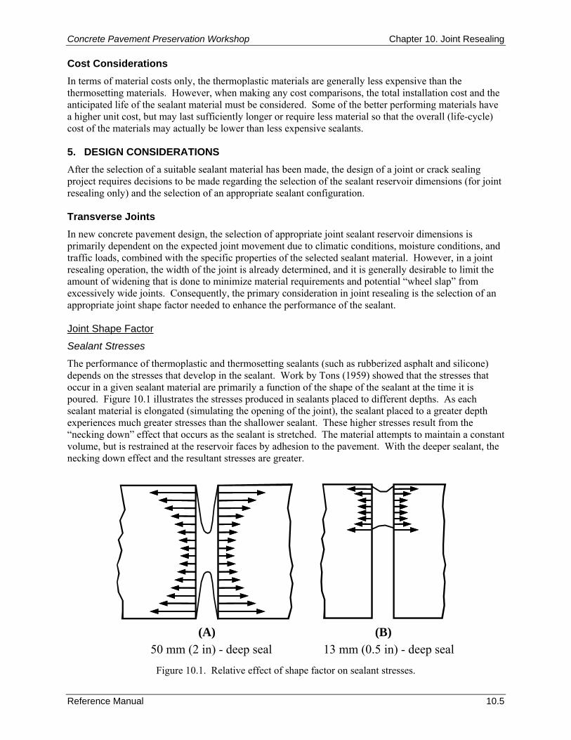
Concrete Pavement Preservation Workshop Chapter 10. Joint Resealing
Reference Manual 10.5
Cost Considerations In terms of material costs only, the thermoplastic materials are generally less expensive than the thermosetting materials. However, when making any cost comparisons, the total installation cost and the anticipated life of the sealant material must be considered. Some of the better performing materials have a higher unit cost, but may last sufficiently longer or require less material so that the overall (life-cycle) cost of the materials may actually be lower than less expensive sealants. 5. DESIGN CONSIDERATIONS After the selection of a suitable sealant material has been made, the design of a joint or crack sealing project requires decisions to be made regarding the selection of the sealant reservoir dimensions (for joint resealing only) and the selection of an appropriate sealant configuration. Transverse Joints In new concrete pavement design, the selection of appropriate joint sealant reservoir dimensions is primarily dependent on the expected joint movement due to climatic conditions, moisture conditions, and traffic loads, combined with the specific properties of the selected sealant material. However, in a joint resealing operation, the width of the joint is already determined, and it is generally desirable to limit the amount of widening that is done to minimize material requirements and potential “wheel slap” from excessively wide joints. Consequently, the primary consideration in joint resealing is the selection of an appropriate joint shape factor needed to enhance the performance of the sealant. Joint Shape Factor
Sealant Stresses
The performance of thermoplastic and thermosetting sealants (such as rubberized asphalt and silicone) depends on the stresses that develop in the sealant. Work by Tons (1959) showed that the stresses that occur in a given sealant material are primarily a function of the shape of the sealant at the time it is poured. Figure 10.1 illustrates the stresses produced in sealants placed to different depths. As each sealant material is elongated (simulating the opening of the joint), the sealant placed to a greater depth experiences much greater stresses than the shallower sealant. These higher stresses result from the “necking down” effect that occurs as the sealant is stretched. The material attempts to maintain a constant volume, but is restrained at the reservoir faces by adhesion to the pavement. With the deeper sealant, the necking down effect and the resultant stresses are greater.
50 mm (2 in) - deep seal(A)
13 mm (0.5 in) - deep seal(B)
Figure 10.1. Relative effect of shape factor on sealant stresses.
Chapter 10. Joint Resealing Concrete Pavement Preservation Workshop
10.6 Reference Manual
The dimensions of the in-place sealant are described in terms of a “shape factor.” The shape factor is defined as the ratio of the sealant width (W) to the sealant depth (D), as illustrated in figure 10.2. A proper shape factor minimizes the stresses that develop within the sealant and along the sealant/pavement interface as the joint opens.
3 to 6 mm (0.125 to 0.25 in) recess
SealantDepth
(D)
Width(W)
SealantBackerRod
BackerRod
Figure 10.2. Illustration of sealant shape factor.
For good performance, the sealant must also be kept from bonding to the bottom of the reservoir. A backer rod, also shown in figure 10.2, may be installed in the reservoir to help achieve the desired shape factor, to prevent the sealant from bonding to the bottom of the reservoir, and to prevent the uncured sealant from running down into the crack beneath the reservoir. It is important that the backer rod, which is generally a polyethylene material, be compatible with the selected sealant material. Recommended Shape Factors
The design of a sealant reservoir (i.e., determining how wide to saw the joint and how deep to place the sealant) should take into consideration the amount of strain or deformation from stretching that the sealant will experience. Most hot-poured thermoplastic sealants on the market today are designed to withstand strains of roughly 25 to 35 percent of their original width, whereas silicone sealants are designed to tolerate strains from 50 to 100 percent. As an example, a thermoplastic material placed in a 13-mm (0.5-in) wide joint can withstand an opening of 3 mm (0.125 in) (13 mm x 25 percent) before exceeding a strain of 25 percent. A silicone material placed in a 13-mm (0.5-in) wide joint can withstand an opening of 6.5 mm (0.25 in) (13 mm x 50 percent) before exceeding a strain of 50 percent. Shape factors recommended for different sealant types are summarized in table 10.2 (Evans, Smith, and Romine 1999). It is also generally recommended that the sealant be recessed between 3 and 6 mm (0.125 and 0.25 in) below the surface of the pavement. These recommendations assume that the joints are opened to a uniform width. Longitudinal Joints Because of the limited amount of movement, concrete to concrete longitudinal joints rarely have a designed reservoir. These joints are typically very narrow (around 6 mm [0.25 in] wide) and are commonly sealed with a thermoplastic material. A backer rod may or may not be used.
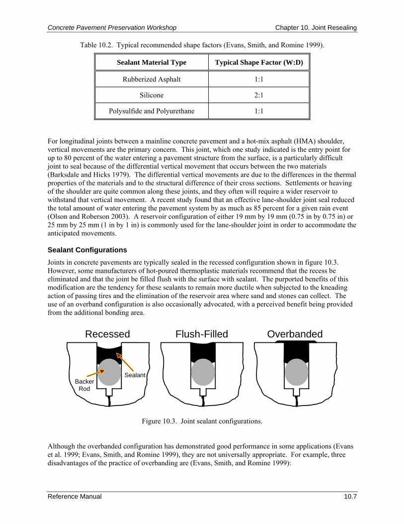
Concrete Pavement Preservation Workshop Chapter 10. Joint Resealing
Reference Manual 10.7
Table 10.2. Typical recommended shape factors (Evans, Smith, and Romine 1999).
Sealant Material Type Typical Shape Factor (W:D)
Rubberized Asphalt 1:1
Silicone 2:1
Polysulfide and Polyurethane 1:1
For longitudinal joints between a mainline concrete pavement and a hot-mix asphalt (HMA) shoulder, vertical movements are the primary concern. This joint, which one study indicated is the entry point for up to 80 percent of the water entering a pavement structure from the surface, is a particularly difficult joint to seal because of the differential vertical movement that occurs between the two materials (Barksdale and Hicks 1979). The differential vertical movements are due to the differences in the thermal properties of the materials and to the structural difference of their cross sections. Settlements or heaving of the shoulder are quite common along these joints, and they often will require a wider reservoir to withstand that vertical movement. A recent study found that an effective lane-shoulder joint seal reduced the total amount of water entering the pavement system by as much as 85 percent for a given rain event (Olson and Roberson 2003). A reservoir configuration of either 19 mm by 19 mm (0.75 in by 0.75 in) or 25 mm by 25 mm (1 in by 1 in) is commonly used for the lane-shoulder joint in order to accommodate the anticipated movements. Sealant Configurations Joints in concrete pavements are typically sealed in the recessed configuration shown in figure 10.3. However, some manufacturers of hot-poured thermoplastic materials recommend that the recess be eliminated and that the joint be filled flush with the surface with sealant. The purported benefits of this modification are the tendency for these sealants to remain more ductile when subjected to the kneading action of passing tires and the elimination of the reservoir area where sand and stones can collect. The use of an overband configuration is also occasionally advocated, with a perceived benefit being provided from the additional bonding area.
SealantBacker
Rod
Recessed Flush-Filled Overbanded
Figure 10.3. Joint sealant configurations. Although the overbanded configuration has demonstrated good performance in some applications (Evans et al. 1999; Evans, Smith, and Romine 1999), they are not universally appropriate. For example, three disadvantages of the practice of overbanding are (Evans, Smith, and Romine 1999):
Chapter 10. Joint Resealing Concrete Pavement Preservation Workshop
10.8 Reference Manual
On high-trafficked pavements, overbanded sealant material is typically worn away by traffic within 1 to 3 years. After the sealant is worn, traffic tires can pull the sealant from the joint edge, leading to adhesion failure.
Snow plow blades used on highways in cold regions tend to damage overbanded sealants by pulling them up form the pavement surface.
The overband can negatively impact ride quality and create an aesthetically unpleasant surface. It should be noted that silicone sealants should never be overbanded or placed flush with the pavement surface. Manufacturers of silicone sealants recommend a minimum of 6 to 9 mm (0.25 to 0.38 in) recess below the surface (Smith et al. 1999). 6. CONSTRUCTION CONSIDERATIONS After the sealant material has been selected, careful attention must be paid to the installation procedure to ensure the sealant provides the desired design life. Many sealing projects have performed poorly because of improper or inadequate installation procedures and practices. Successful sealing projects require close attention to detail. Transverse Joint Resealing The resealing of transverse joints in concrete pavements consists of the following steps, each of which is described in a subsequent section:
1. Old sealant removal.
2. Joint refacing.
3. Joint reservoir cleaning.
4. Backer rod installation.
5. New sealant installation. Step 1: Old Sealant Removal
The first step of the joint resealing process is to remove the old sealant from the joint. Initial removal can be done by any procedure that does not damage the joint itself, such as using a rectangular joint plow or removal with a diamond-bladed saw. Another method that has been used is high pressure waterblasting. Diamond-bladed sawing as a means of sealant removal has gained acceptance because it combines the sealant removal and refacing steps in a single process. It is most effective at removing existing silicone sealants and existing thermoplastic sealants when they have hardened and will not melt and “gum-up” the saw blade or joint face. Complete removal of the old sealant is not required for the entire depth of the joint if the required reservoir depth is less than the existing sealant that is present. However, if there are incompressibles present, the old sealant should be completely removed to ensure free-moving, clean joints.
Step 2: Joint Refacing
The purpose of the refacing operation is to provide a clean surface for bonding with the new sealant and to establish a reservoir of the proper size to produce the desired shape factor. If a diamond-bladed saw has been used for sealant removal, refacing can be performed at the same time. If a joint plow or some other means has been used to remove the old sealant material, then a separate joint refacing operation must be performed.
Concrete Pavement Preservation Workshop Chapter 10. Joint Resealing
Reference Manual 10.9
Refacing is generally done using a water-cooled saw with diamond blades. A single full-width blade is useful for maintaining joint width; however, the edges wear quickly, reducing the effectiveness of the sawing. Two blades separated by a spacer to the desired width can be used on the same arbor. The core diameter of these blades should be at least 4.8 mm (0.19 in) to keep the blades from toeing into the joint. Blade overheating and warping can result from using thin blades. Typically, a joint is widened by 3 mm (0.125 in); 1.5 mm (0.0625 in) on each face. Care should be exercised when refacing; joint reservoirs that are widened excessively will increase the probability of “wheel slap” creating unwanted noise. Routers have also been used to reface joint reservoirs, but their production is much slower than diamond-bladed saws. In addition, they can leave irregular or spalled joint walls and may smear the existing sealant on the sidewalls. Therefore, the use of routers is not recommended for joint refacing operations. Step 3: Joint Reservoir Cleaning
The importance of effective cleaning of the joint sidewalls cannot be over-emphasized. Dirty or poorly cleaned joint or crack sidewalls can reduce the performance of even the best sealant and the most reliable sealant reservoir design. Several common materials that may contaminate the joint sidewalls include:
Old sealant left on the joint or crack sidewalls.
Water-borne dust (laitance) from the sawing operation.
Oil or water introduced by the compressed air stream.
Dust and dirt not removed during the cleaning operation.
Debris entering the joint after cleaning and prior to sealing.
Other contaminants that may inhibit bonding, such as moisture condensation. Immediately after joint refacing, the joint should be cleaned with high-pressure air or water followed by sandblasting. Sandblasting effectively removes laitance (wet-sawing dust) and any other residue on the joint faces, and should be conducted in two passes so that each joint face is cleaned. Air compressors used with the sandblasters must be equipped with working water and oil traps to prevent contamination of the joint bonding faces. Compressors should be tested prior to sandblasting operations using a clean white cloth to ensure oil/water free operations. The use of hot-air lances to dry joint reservoirs should be used with caution, as overheating can damage the concrete (ACPA 2004). Following sandblasting, the entire length of each joint face should be visibly clean with exposed concrete. Very close attention must be paid to the sandblasting operation to ensure consistent, thorough cleaning. During the sandblasting operation, a proper helmet and breathing apparatus and any other appropriate safety equipment should be used to protect the operator. Immediately prior to backer rod and sealant installation, the joints should be blown again with high pressure (> 621 kPa [90 lbf/in2]) clean, dry air to remove sand, dust, and other incompressibles that remain in the joint. A backpack blower typically cannot generate sufficient pressure to clean joints thoroughly and should not be used for final cleaning. Joints and surrounding surfaces should be airblown in one direction away from prevailing winds, taking care not to contaminate previously cleaned joints. Care must also be taken not to blow debris into traffic in adjacent lanes. Power-driven wire brushes should never be used to remove old sealant or to clean a joint in a concrete pavement. This procedure is essentially ineffective and can smear the old sealant across the concrete sidewall, creating a surface to which the new sealant cannot bond.
Chapter 10. Joint Resealing Concrete Pavement Preservation Workshop
10.10 Reference Manual
Step 4: Backer Rod Installation
Typical backer rod materials include polychloroprene, polystyrene, polyurethane, and polyethylene closed-cell materials; paper, rope, or cord should not be used (ACPA 2006). The backer rod should be installed as soon as possible after the joints are airblasted. The backer rod should be approved by the sealant manufacturer, and be about 25 percent larger in diameter than the joint width. The backer rod must be a flexible, nonabsorptive material that is compatible with the sealant material in use. The melting temperature of the backer material should be at least 14 °C (25 °F) higher than the sealant application temperature to prevent damage during sealant placement (ACPA 2006). Wide joints or segments of joints in which the backer rod does not provide a tight seal should be filled with larger diameter backer rod. The backer rod should be installed to the proper depth and no gaps should exist at the intersections of backer rod strips. The rod should be stretched as little as possible to reduce the likelihood of shrinkage and the resultant formation of gaps. Step 5: New Sealant Installation
As soon as possible after backer rod placement, the sealant material should be installed. This helps to avoid problems that occur when the backer rod is left in place too long before the sealant is placed, such as condensation on the backer rod and debris collecting in the reservoir. An additional check to verify that the reservoirs are clean and dry helps to ensure good long-term performance. Hot-Poured Thermoplastic Sealant Materials
Hot-poured thermoplastic sealant materials should be placed only when the air temperature is at least 4 ºC (40 ºF) and rising (FHWA 2002). The sealant material should be installed in a uniform manner, filling the reservoir from the bottom up to avoid trapping any air bubbles. The joint reservoir must not be overfilled during the sealing operation. It is generally recommended that the surface of the sealant be recessed at least 3 to 6 mm (0.125 to 0.25 in) below the surface of the pavement to allow room for sealant expansion during the summer when the joint closes, without extruding the sealant to the point where traffic can pull it from the joint. However, as mentioned previously, some manufacturers recommend that the joint be filled to the surface with sealant. In any case, to avoid “tracking” of the sealant, traffic should not be allowed on the newly sealed joints for about 30 minutes to 1 hour after sealant placement. The sealant manufacturer should be consulted for recommendations on when the sealant can be exposed to traffic. It is also important to follow the manufacturer’s recommendations with regard to the maximum sealant temperature, the recommended placement temperature, and any prolonged heating limitations. Many of the polymer- and rubber-modified sealants break down when subjected to temperatures above the recommended safe heating temperature. Prolonged heating can cause some sealant materials to gel in the heating tank, while others experience significant changes in their elastic properties. Sealant material that has been overheated tends to burn onto the hot surfaces of the inside of the melter/applicator. This burnt material, if remixed into the new sealant, can reduce sealant performance. Using an additional thermometer to monitor sealant temperatures can help eliminate damage due to sealant overheating. Silicone Sealants
Silicone sealants should not be placed at temperatures below 4 ºC (40 ºF). As with the thermoplastic materials, silicone sealants should be installed in a uniform manner, from the bottom to the top of the joint, to ensure that no air is entrapped. Low-modulus silicone sealants have properties that allow them to be placed with shape factors of 2. It is not recommended that they be placed any thinner than half the width of the joint, with a minimum thickness of 6 mm (0.25 in). Traffic should not be allowed on the pavement for about 1 hour after sealant placement. Again, the sealant manufacturer should be consulted for recommendations on when the sealant can be exposed to traffic.
Concrete Pavement Preservation Workshop Chapter 10. Joint Resealing
Reference Manual 10.11
As mentioned previously, silicone materials come in two varieties: self-leveling and nonself-leveling. The nonself-leveling silicone sealants must be tooled to force the sealant around the backer rod and against the joint sidewalls. This tooling should also form a concave sealant surface with the lowest point being about 6 mm (0.25 in) below the pavement surface. Successful tooling has been accomplished using such devices as a rubber hose on the end of a fiberglass rod or pieces of a large diameter backer rod. Self-leveling silicone sealants do not require this tooling operation. Extra care, however, must be taken with placing backer rod for self-leveling silicone sealants, as the sealant can easily flow around loose backer rod prior to curing. Sealant can also flow out at the joint ends if not properly blocked. Even though these sealants do not require tooling, some agencies have mandated tooling in order to enhance the bond between the pavement and the sealant. When installing both silicone and thermoplastic sealants, such as in a project with silicone sealant in the transverse joints and hot-poured thermoplastic materials in the longitudinal joint, the silicone should be installed first to reduce the potential for contamination of the transverse joint during the longitudinal joint sealing operations. Other Thermosetting Sealants
Other thermosetting sealants, such as polysulfides and polyurethanes, require a curing period to gain their strength and resiliency. Most polymeric thermosetting sealants consist of two components that are carefully mixed as the material is being placed in the joint. These sealants require a special application nozzle and careful control of the application equipment. Quality control should include testing the sealant for adequate cure, and traffic should not be allowed on these sealants until the surface has skinned over and the possibility for stone intrusion is minimized. Longitudinal Joint Resealing As previously described, two types of longitudinal joints in concrete pavements may also be addressed as part of a resealing operation: longitudinal joints between adjacent concrete pavement slabs, and the longitudinal joint between the mainline concrete pavement and an HMA shoulder. While the procedures are essentially the same as transverse joint resealing, some additional considerations should be noted. Concrete to Concrete Longitudinal Joints
Longitudinal joints between adjacent concrete slabs are found between adjacent traffic lanes or between a concrete mainline pavement and a concrete shoulder. This joint is generally tied together with deformed tiebars so that movements are not excessive and conventional joint sealing operations can be followed. Because of the limited amount of movement that occurs at these joints, they are generally sealed with a hot-poured thermoplastic material. In the resealing operation, typically no reservoir is formed or needed. If the transverse joints are to be sealed with silicone, it is important that the longitudinal joints be sealed last to prevent contamination of the transverse joints with hot-poured thermoplastic material. Concrete Mainline/HMA Shoulder Joint
The longitudinal joint between a concrete mainline pavement and a HMA shoulder can be a very difficult joint to seal. The differences in the thermal properties of each material and the differences in the structural cross section often result in large differential vertical movements. Additionally, significant horizontal movement, or separation, often accompanies the vertical movement. Because water easily infiltrates the pavement structure at this type of joint, it should be sealed to minimize water infiltration.
Chapter 10. Joint Resealing Concrete Pavement Preservation Workshop
10.12 Reference Manual
Again, the steps required for the sealing of lane-shoulder joint are the same as transverse joint sealing operations. However, it is important that a sufficiently wide reservoir be cut in the existing HMA shoulder to allow for the anticipated vertical movements. Common reservoir dimensions range from 19 mm by 19 mm (0.75 in by 0.75 in) to 25 mm by 25 mm (1 in by 1 in). The reservoir can be created using either a router or a diamond-bladed saw. The reservoir should be cleaned prior to the placement of the sealant material. A backer rod is generally not needed if proper depth control during the creation of the reservoir has been maintained. Many agencies use hot-poured thermoplastic materials to seal this joint, although there are some silicone materials that have been specifically developed for this type of application. Crack Sealing With the exception of a sealant removal step, the sealing of cracks in concrete pavements essentially follows the same basic steps as the sealing of joints: refacing, cleaning, backer rod installation, and sealant installation (ACPA 1995). The first step is to reface the crack to the desired width. However, the random orientation of most concrete pavement cracks makes it difficult to create a uniform sealant reservoir directly over the crack. The formation of a reservoir should be accomplished with a small diameter diamond-bladed saw (ACPA 2006). Note that while crack routers have been used in the past to form sealant reservoirs, their use is not recommended due to the chipping and micro-cracking damage this equipment causes to the concrete (ACPA 2004). The cutting blades for the crack saws are typically 175 to 200 mm (7 to 8 in) in diameter and 6 to 13 mm (0.25 to 0.5 in) wide. The width of the saw cut generally provides an appropriate shape factor to accommodate the expected crack movement. Smaller blade diameters, in addition to lightweight two- or three-wheel unit designs, allow crack saws to pivot and follow irregular crack profiles. Once the reservoir is created, the crack should be cleaned following those steps prescribed for joint resealing. Sandblasting is particularly recommended to remove laitance from the sawing operation. After cleaning, the crack is blown with compressed air and the backer rod (if specified) and sealant material are installed. The same precautions that apply to the installation of sealant materials into joints also apply here (ACPA 1995). Construction Equipment A brief description of the equipment used in joint and crack sealing operations is included in this section. Equipment for Sealant Removal and Joint/Crack Refacing
Joint Plow
A joint plow is a rectangular blade mounted on the hydraulic mount of a tractor or the bucket of a skid loader. The plow blade is inserted into the joint and pulled along each joint edge, scraping the sealant from the sidewalls. The blade must be rectangular and fit freely into the joint. A V-shaped blade should not be used because these blades can spall the joint. The rectangular tool must be mounted such that it is free to move vertically and horizontally in the joint without binding. Blades of several widths should be on hand, as joint widths are seldom uniform over an entire project. Diamond-Bladed Saw
Diamond-bladed saws are typically 26 to 46 kW (35 to 65 hp), water-cooled devices equipped with diamond-edged blades. A single, full-width blade is useful for maintaining joint width; however, the edges wear quickly, reducing the effectiveness of the sawing. Two blades separated by a spacer to the desired width can be used on the same arbor.
Concrete Pavement Preservation Workshop Chapter 10. Joint Resealing
Reference Manual 10.13
Equipment for Joint Cleaning
Sandblasting Equipment
Sandblasting equipment consists of a compressed air unit, a sandblasting machine, hoses, and a wand with a venturi-type nozzle. The compressed air supply is the most critical part of the sandblasting operation. At least 620 kPa (90 lbf/in2) of pressure and 4.3 m3/min (150 ft3/min) of oil- and moisture-free air should be provided. Additionally, the use of a jig is recommended to reduce operator fatigue and ensure that the sandblast nozzle is properly positioned to direct sand against the sidewalls to provide more efficient cleaning (Evans, Smith, and Romine 1999). Airblasting Equipment
Airblasting equipment consists of high-pressure air compressors with hoses and wands. High-pressure air compressors are effective at removing dust and debris from a joint, but are not as effective as sandblasting at removing laitance. As a minimum, compressed air units should have a blast pressure of 690 kPa (100 lbf/in2) and a blast volume of 4.3 m3/min (150 ft3/min). Equipment for Joint Sealant Placement
Melters
Hot-poured thermoplastic materials are heated and mixed in an indirect-heat, agitator-type melter. These machines burn either propane or diesel fuel, and the resulting heat is applied to a transfer oil that surrounds a double-jacketed melting vat containing the sealant material. This indirect method of heating is safer and provides a more controlled and uniform heat. Silicone Pumps
One-component silicone materials are typically pumped from storage containers using compressed air powered pumping equipment. A feed rate of at least 1.5 L/min (0.4 gal/min) is recommended and the wand should be equipped with a nozzle that allows filling from the bottom up. Applicators
Most sealant applicators are pressure-wand systems, normally equipped on sealant melters. The applicator consists of a pump, hoses, and an applicator wand. Sealant material is pumped directly from the melter-vat through the system and into the joint. Some low-productivity, filling operations use a cornucopia pour pot, which is a hand-held, conical-shaped pot used to apply unheated or partially-heated emulsions into joints. 7. QUALITY CONTROL Proper sealant application is a process that relies heavily upon the care and conscientiousness of the contractor. Paying close attention to this quality during construction greatly increases the chances of minimizing premature failures on joint resealing and crack sealing projects. The remainder of this section summarizes the QC recommendations summarized in a recent FHWA checklist (FHWA 2002). Preliminary Responsibilities Prior to the commencing of construction procedures, the agency should conduct a review of pertinent project-related documents, the project’s current condition, and materials to be used on the project. The following specific lists of items are provided as a model QC checklist for these preliminary items. Document Review
All of the following documents should be reviewed prior to the start of any construction activities (FHWA 2002):
Chapter 10. Joint Resealing Concrete Pavement Preservation Workshop
10.14 Reference Manual
Bid/project specifications and design.
Special provisions.
Traffic control plan.
Manufacturer’s sealant installation instructions.
Material safety data sheets (MSDS).
Agency application requirements. Any suspected problems should be identified and reconciled as part of the preliminary review process. Project Review
An updated review of the current project’s condition is warranted to ensure that the project is still a viable candidate for joint resealing or crack sealing. Specifically, it should be verified that conditions have not significantly changed since the project was designed, and that the prevailing distresses are still in the acceptable ranges used for project selection. Also, the selected methods for sealant removal, refacing, and cleaning should be reviewed. Finally, for joint resealing projects, the selected joint design and sealant type should be reviewed to make sure they are still appropriate for the expected project climate and conditions. Review of Materials
In preparation for the construction project, the following list summarizes many of the material-related items that should be checked or reviewed prior to construction (FHWA 2002):
Sealant meets specification requirements.
Sealant material is from an approved source or listed on agency qualified products list (QPL) (if required).
Sealant material has been sampled and tested prior to installation (if required).
Sealant material packaging is not damaged (i.e., leaking, torn, or pierced).
Backer rod is of the proper size and type for the selected sealant material.
Chemically curing sealants (if used) are within shelf life.
Sufficient quantities of all materials are available for completion of the project. Inspection of Equipment
Prior to beginning construction, all construction equipment must be examined. The following sections describe equipment-related items (specific to the different available sealant types) that should be checked prior to construction (FHWA 2002). Hot-Applied Sealant Melters
For hot-applied sealant melters, an indirectly heated double boiler type melter with effective agitation is typically used. Prior to construction, these melters should be inspected to ensure that they are in good working order with all internal mechanisms (such as heating, agitation, pumping systems, valves, and thermostats) functioning properly. Also, the contractor should verify that the proper size wand tips are available.
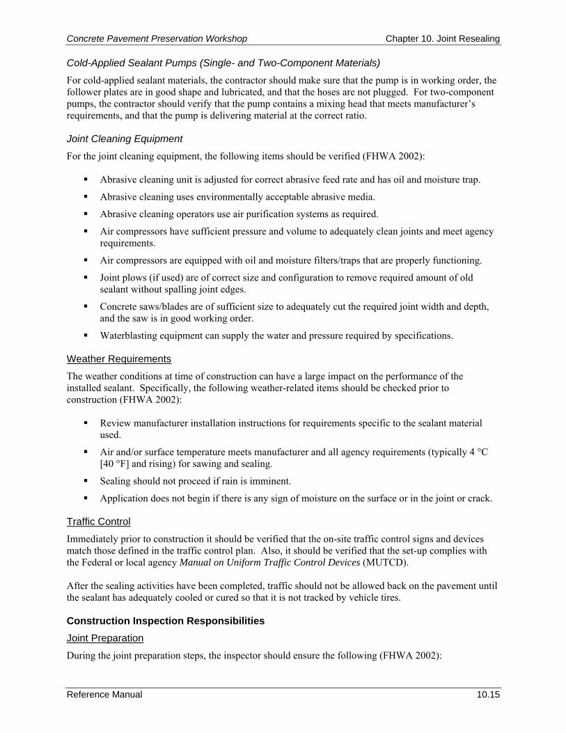
Concrete Pavement Preservation Workshop Chapter 10. Joint Resealing
Reference Manual 10.15
Cold-Applied Sealant Pumps (Single- and Two-Component Materials)
For cold-applied sealant materials, the contractor should make sure that the pump is in working order, the follower plates are in good shape and lubricated, and that the hoses are not plugged. For two-component pumps, the contractor should verify that the pump contains a mixing head that meets manufacturer’s requirements, and that the pump is delivering material at the correct ratio. Joint Cleaning Equipment
For the joint cleaning equipment, the following items should be verified (FHWA 2002):
Abrasive cleaning unit is adjusted for correct abrasive feed rate and has oil and moisture trap.
Abrasive cleaning uses environmentally acceptable abrasive media.
Abrasive cleaning operators use air purification systems as required.
Air compressors have sufficient pressure and volume to adequately clean joints and meet agency requirements.
Air compressors are equipped with oil and moisture filters/traps that are properly functioning.
Joint plows (if used) are of correct size and configuration to remove required amount of old sealant without spalling joint edges.
Concrete saws/blades are of sufficient size to adequately cut the required joint width and depth, and the saw is in good working order.
Waterblasting equipment can supply the water and pressure required by specifications. Weather Requirements
The weather conditions at time of construction can have a large impact on the performance of the installed sealant. Specifically, the following weather-related items should be checked prior to construction (FHWA 2002):
Review manufacturer installation instructions for requirements specific to the sealant material used.
Air and/or surface temperature meets manufacturer and all agency requirements (typically 4 °C [40 °F] and rising) for sawing and sealing.
Sealing should not proceed if rain is imminent.
Application does not begin if there is any sign of moisture on the surface or in the joint or crack. Traffic Control
Immediately prior to construction it should be verified that the on-site traffic control signs and devices match those defined in the traffic control plan. Also, it should be verified that the set-up complies with the Federal or local agency Manual on Uniform Traffic Control Devices (MUTCD). After the sealing activities have been completed, traffic should not be allowed back on the pavement until the sealant has adequately cooled or cured so that it is not tracked by vehicle tires. Construction Inspection Responsibilities Joint Preparation
During the joint preparation steps, the inspector should ensure the following (FHWA 2002):

Chapter 10. Joint Resealing Concrete Pavement Preservation Workshop
10.16 Reference Manual
All safety mechanisms and guards on equipment are in place and functioning properly, and operators are using required personal protective equipment.
Old sealant is removed from the joint.
Joint is refaced to produce a joint reservoir that coincides with the selected sealant material.
After refacing, joints are flushed with high pressure water to remove all saw slurry and debris.
Joint surfaces are cleaned using abrasive cleaning or waterblasting.
Abrasive cleaning is accomplished with the nozzle 25 to 50 mm (1 to 2 in) above the joint using two passes (each directed at one of the joint faces).
Joint is blown clean with clean dry air. A propane torch or hot-air lance should not be used for drying.
Joint is inspected prior to sealing by rubbing finger along the joint walls to insure that no contaminants (dust, dried saw residue, dirt, moisture, or oil) are on the joint walls. If dust or other contaminants are present, reclean the joint to a satisfactory condition.
Backer Rod Installation
During the backer rod installation process, the inspector should check that the backer rod is being installed uniformly to the required depth. Also, the inspector should check that the backer rod fits snugly in the joint (no gaps along the side), and is not being stretched or damaged during installation. Sealant Installation
Hot-Applied Sealants
As previously discussed, many of the newer sealant materials are sensitive to heating and application temperatures. The use of supplementary temperature monitoring devices is recommended so that the sealant temperature can be closely observed. Underheating the material results in poor bonding, while overheating the material destroys its ductile properties and increases its aging. More specifically, as part of a comprehensive QC plan, a project inspector should check or verify the following:
Melter heat transfer medium is heated to the correct temperature range.
Sealant is being heated into the manufacturer’s recommended pouring or application temperature range. In addition, the inspector should check that the heating temperature does not exceed the material’s safe heating temperature.
Sealant is continuously agitated to assure uniformity, except when adding additional material.
Operator wears required personal protective equipment.
If melter is equipped with a heated hose system, the hose is heated prior to beginning sealant application.
If melter does not have a heated hose, verify that the hose is unplugged and clear prior to beginning sealant application.
If melter does not have a heated hose, the sealant should be recirculated through the hose to warm the hose prior to application. During idle periods, or if it is noted that sealant is cooling in the hose, sealant shall be recirculated through the hose back to the material vat to keep the hose at an acceptable temperature.
Melting vat should be kept at least one-third full to help maintain temperature uniformity.
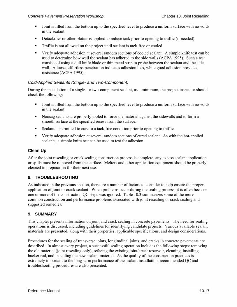
Concrete Pavement Preservation Workshop Chapter 10. Joint Resealing
Reference Manual 10.17
Joint is filled from the bottom up to the specified level to produce a uniform surface with no voids in the sealant.
Detackifier or other blotter is applied to reduce tack prior to opening to traffic (if needed).
Traffic is not allowed on the project until sealant is tack-free or cooled.
Verify adequate adhesion at several random sections of cooled sealant. A simple knife test can be used to determine how well the sealant has adhered to the side walls (ACPA 1995). Such a test consists of using a dull knife blade or thin metal strip to probe between the sealant and the side wall. A loose, effortless penetration indicates adhesion loss, while good adhesion provides resistance (ACPA 1995).
Cold-Applied Sealants (Single- and Two-Component)
During the installation of a single- or two-component sealant, as a minimum, the project inspector should check the following:
Joint is filled from the bottom up to the specified level to produce a uniform surface with no voids in the sealant.
Nonsag sealants are properly tooled to force the material against the sidewalls and to form a smooth surface at the specified recess from the surface.
Sealant is permitted to cure to a tack-free condition prior to opening to traffic.
Verify adequate adhesion at several random sections of cured sealant. As with the hot-applied sealants, a simple knife test can be used to test for adhesion.
Clean Up After the joint resealing or crack sealing construction process is complete, any excess sealant application or spills must be removed from the surface. Melters and other application equipment should be properly cleaned in preparation for their next use. 8. TROUBLESHOOTING As indicated in the previous section, there are a number of factors to consider to help ensure the proper application of joint or crack sealant. When problems occur during the sealing process, it is often because one or more of the construction QC steps was ignored. Table 10.3 summarizes some of the more common construction and performance problems associated with joint resealing or crack sealing and suggested remedies. 9. SUMMARY This chapter presents information on joint and crack sealing in concrete pavements. The need for sealing operations is discussed, including guidelines for identifying candidate projects. Various available sealant materials are presented, along with their properties, applicable specifications, and design considerations. Procedures for the sealing of transverse joints, longitudinal joints, and cracks in concrete pavements are described. In almost every project, a successful sealing operation includes the following steps: removing the old material (joint resealing only), refacing the existing joint/crack reservoir, cleaning, installing backer rod, and installing the new sealant material. As the quality of the construction practices is extremely important to the long-term performance of the sealant installation, recommended QC and troubleshooting procedures are also presented.
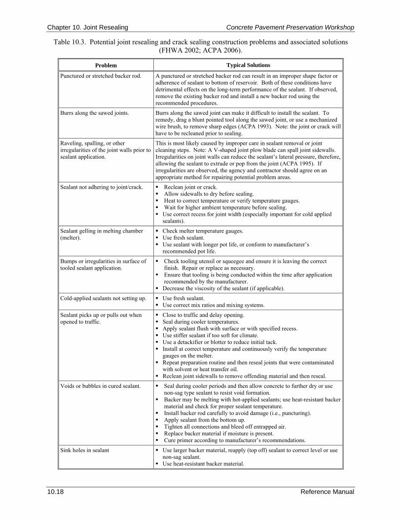
Chapter 10. Joint Resealing Concrete Pavement Preservation Workshop
10.18 Reference Manual
Table 10.3. Potential joint resealing and crack sealing construction problems and associated solutions (FHWA 2002; ACPA 2006).
Problem Typical Solutions
Punctured or stretched backer rod. A punctured or stretched backer rod can result in an improper shape factor or adherence of sealant to bottom of reservoir. Both of these conditions have detrimental effects on the long-term performance of the sealant. If observed, remove the existing backer rod and install a new backer rod using the recommended procedures.
Burrs along the sawed joints. Burrs along the sawed joint can make it difficult to install the sealant. To remedy, drag a blunt pointed tool along the sawed joint, or use a mechanized wire brush, to remove sharp edges (ACPA 1993). Note: the joint or crack will have to be recleaned prior to sealing.
Raveling, spalling, or other irregularities of the joint walls prior to sealant application.
This is most likely caused by improper care in sealant removal or joint cleaning steps. Note: A V-shaped joint plow blade can spall joint sidewalls. Irregularities on joint walls can reduce the sealant’s lateral pressure, therefore, allowing the sealant to extrude or pop from the joint (ACPA 1995). If irregularities are observed, the agency and contractor should agree on an appropriate method for repairing potential problem areas.
Sealant not adhering to joint/crack. Reclean joint or crack. Allow sidewalls to dry before sealing. Heat to correct temperature or verify temperature gauges. Wait for higher ambient temperature before sealing. Use correct recess for joint width (especially important for cold applied
sealants).
Sealant gelling in melting chamber (melter).
Check melter temperature gauges. Use fresh sealant. Use sealant with longer pot life, or conform to manufacturer’s
recommended pot life.
Bumps or irregularities in surface of tooled sealant application.
Check tooling utensil or squeegee and ensure it is leaving the correct finish. Repair or replace as necessary.
Ensure that tooling is being conducted within the time after application recommended by the manufacturer.
Decrease the viscosity of the sealant (if applicable).
Cold-applied sealants not setting up. Use fresh sealant. Use correct mix ratios and mixing systems.
Sealant picks up or pulls out when opened to traffic.
Close to traffic and delay opening. Seal during cooler temperatures. Apply sealant flush with surface or with specified recess. Use stiffer sealant if too soft for climate. Use a detackifier or blotter to reduce initial tack. Install at correct temperature and continuously verify the temperature
gauges on the melter. Repeat preparation routine and then reseal joints that were contaminated
with solvent or heat transfer oil. Reclean joint sidewalls to remove offending material and then reseal.
Voids or bubbles in cured sealant. Seal during cooler periods and then allow concrete to further dry or use non-sag type sealant to resist void formation.
Backer may be melting with hot-applied sealants; use heat-resistant backer material and check for proper sealant temperature.
Install backer rod carefully to avoid damage (i.e., puncturing). Apply sealant from the bottom up. Tighten all connections and bleed off entrapped air. Replace backer material if moisture is present. Cure primer according to manufacturer’s recommendations.
Sink holes in sealant Use larger backer material, reapply (top off) sealant to correct level or use non-sag sealant.
Use heat-resistant backer material.
Concrete Pavement Preservation Workshop Chapter 10. Joint Resealing
Reference Manual 10.19
10. REFERENCES American Concrete Pavement Association (ACPA). 1995. Joint and Crack Sealing and Repair for Concrete Pavements. Technical Bulletin TB012P. American Concrete Pavement Association, Skokie, IL.
American Concrete Pavement Association (ACPA). 2004. Concrete Crack and Partial-Depth Spall Repair Manual. Report JP003P. American Concrete Pavement Association, Skokie, IL.
American Concrete Pavement Association (ACPA). 2006. Concrete Pavement Field Reference - Preservation and Repair. Report EB239P. American Concrete Pavement Association, Skokie, IL.
Barksdale, R. D. and R. G. Hicks. 1979. Improved Pavement-Shoulder Joint Design. NCHRP Report 202. Transportation Research Board, Washington, DC.
Evans, L. D., M. A. Pozsgay, K. L. Smith, and A. R. Romine. 1999. LTPP Pavement Maintenance Materials: SHRP Joint Reseal Experiment, Final Report. FHWA-RD-99-142. Federal Highway Administration, McLean, VA.
Evans, L. D., K. L. Smith, and A. R. Romine. 1999. Materials and Procedures for the Repair of Joint Seals in Portland Cement Concrete Pavements—Manual of Practice. FHWA-RD-99-146. Federal Highway Administration, McLean, VA.
Federal Highway Administration (FHWA). 2002. Pavement Preservation Checklist Series #9: Joint Sealing Portland Cement Concrete Pavements. FHWA-IF-03-003. Federal Highway Administration, Washington, DC.
Hall, K. T. and J. A. Crovetti. 2000. LTPP Data Analysis: Relative Performance of Jointed Plain Concrete Pavements with Sealed and Unsealed Joints. Final Report, NCHRP Project 20-50(02). Web Document 32. Transportation Research Board, Washington, DC.
McGhee, K. H. 1995. Design, Construction, and Maintenance of PCC Pavement Joints. NCHRP Synthesis of Highway Practice 211. Transportation Research Board, Washington, DC.
Olson, R. and R. Roberson. 2003. Edge-Joint Sealing as a Preventive Maintenance Practice. Report No. MN/RC 2003-26. Minnesota Department of Transportation, St. Paul, MN.
Permanent International Association of Road Congresses (PIARC). 1992. Evaluation and Maintenance of Concrete Pavements. Permanent International Association of Road Congresses, Paris, France.
Peterson, D. E. 1982. Resealing Joints and Cracks in Rigid and Flexible Pavements. NCHRP Synthesis of Highway Practice 98. Transportation Research Board, Washington, DC.
Shober, S. F. 1986. “Portland Cement Concrete Pavement Performance as Influenced by Sealed and Unsealed Contraction Joints.” Transportation Research Record 1083. Transportation Research Board, Washington, DC.
Shober, S. F. 1997. “The Great Unsealing: A Perspective on Portland Cement Concrete Joint Sealing.” Transportation Research Record 1597. Transportation Research Board, Washington, DC.
Smith, K. L., D. G. Peshkin, E. H. Rmeili, T. Van Dam, K. D. Smith, and M. I. Darter. 1991. Innovative Materials and Equipment for Pavement Surface Repairs, Volume I: Summary of Material Performance and Experimental Plans. SHRP-M/UFR-91-504. Strategic Highway Research Program, Washington, DC.
Smith, K. L., M. A. Pozsgay, L. D. Evans, and A. R. Romine. 1999. LTPP Pavement Maintenance Materials: SPS-4 Supplemental Joint Seal Experiment, Final Report. FHWA-RD-99-151. Federal Highway Administration, McLean, VA.
Tons, E. 1959. “A Theoretical Approach to Design of a Road Joint Seal.” Highway Research Board Bulletin 229. Highway Research Board, Washington, DC.

Chapter 10. Joint Resealing Concrete Pavement Preservation Workshop
10.20 Reference Manual
NOTES
Concrete Pavement Preservation Workshop Chapter 11. Strategy Selection
Reference Manual 11.1
CHAPTER 11. STRATEGY SELECTION 1. LEARNING OUTCOMES This manual has discussed in detail a variety of concrete pavement preservation and restoration techniques. These range from relatively simple and straightforward treatments, such as joint resealing, to more involved techniques, such as full-depth repairs and retrofitted load transfer devices. So far, however, no guidance has been provided on determining which treatment (or which combination of treatments) is appropriate for a given concrete pavement project. The selection of an appropriate preservation or rehabilitation treatment for a given concrete pavement project requires a systematic, step-by-step approach that considers all relevant factors. This chapter outlines a recommended step-by-step procedure that can be used to select the most appropriate treatment types or strategies. Upon successful completion of this chapter, the participants will be able to accomplish the following:
1. Describe the treatment selection process.
2. List the components of a life-cycle cost analysis (LCCA).
3. List other factors that might enter into the selection process. 2. INTRODUCTION Across the country, the maintenance and rehabilitation of the existing highway network has become a central focus. The need to maintain the nation’s already-constructed network is essential to the economical operation of the overall transportation system. Because of increasing financial constraints, accomplishing this task has become more and more difficult over the years. Therefore, both the traveling public and highway agencies alike are seeking better solutions to their mutual concerns about the operating conditions on the nation’s roads. The incorporation of pavement preservation is viewed to be essential to this process as these techniques have been shown to be effective at delaying more costly and invasive rehabilitation procedures, thereby providing longer service lives, minimizing traffic disruptions, reducing the work zone risks to both workers and highway users, and minimizing life-cycle costs. Determining the right treatment for the right pavement at the right time can be a complex procedure that requires simultaneously evaluating a number of different influencing factors. This chapter provides information about the types of factors that should be considered when selecting an appropriate preservation strategy for a given pavement. Included among these factors is a life-cycle cost analysis, which is introduced as one way of evaluating the overall cost-effectiveness of competing strategies. 3. TREATMENT SELECTION PROCESS Overview of the Selection Process Whenever an evaluation of an individual project is conducted, the immediate goal of that evaluation is to identify the deficiencies in the pavement, and then ultimately to determine how to best address those deficiencies. Typically, the first decision is to determine how extensive the needs are for the pavement. For example, if the pavement is only exhibiting functional deficiencies or localized structural problems, the observed deficiencies can most likely be addressed with one or more concrete pavement preservation activities. If more global structural or material problems exist, then the pavement section is more likely suited for an asphalt or concrete overlay, or perhaps even complete reconstruction in the most severe case. Because discussions of overlays or reconstruction are outside the scope of this course, this chapter focuses on the selection of the most appropriate concrete pavement preservation treatments.
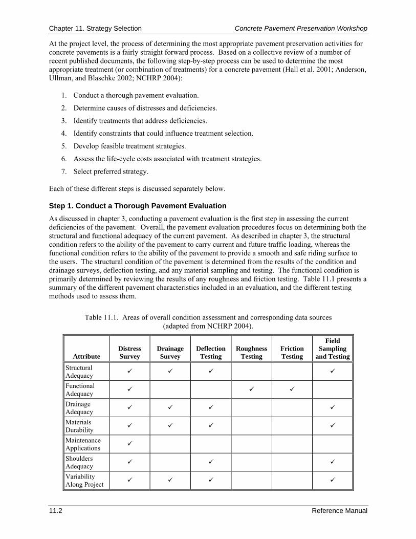
Chapter 11. Strategy Selection Concrete Pavement Preservation Workshop
11.2 Reference Manual
At the project level, the process of determining the most appropriate pavement preservation activities for concrete pavements is a fairly straight forward process. Based on a collective review of a number of recent published documents, the following step-by-step process can be used to determine the most appropriate treatment (or combination of treatments) for a concrete pavement (Hall et al. 2001; Anderson, Ullman, and Blaschke 2002; NCHRP 2004):
1. Conduct a thorough pavement evaluation.
2. Determine causes of distresses and deficiencies.
3. Identify treatments that address deficiencies.
4. Identify constraints that could influence treatment selection.
5. Develop feasible treatment strategies.
6. Assess the life-cycle costs associated with treatment strategies.
7. Select preferred strategy. Each of these different steps is discussed separately below. Step 1. Conduct a Thorough Pavement Evaluation As discussed in chapter 3, conducting a pavement evaluation is the first step in assessing the current deficiencies of the pavement. Overall, the pavement evaluation procedures focus on determining both the structural and functional adequacy of the current pavement. As described in chapter 3, the structural condition refers to the ability of the pavement to carry current and future traffic loading, whereas the functional condition refers to the ability of the pavement to provide a smooth and safe riding surface to the users. The structural condition of the pavement is determined from the results of the condition and drainage surveys, deflection testing, and any material sampling and testing. The functional condition is primarily determined by reviewing the results of any roughness and friction testing. Table 11.1 presents a summary of the different pavement characteristics included in an evaluation, and the different testing methods used to assess them.
Table 11.1. Areas of overall condition assessment and corresponding data sources (adapted from NCHRP 2004).
Attribute Distress Survey
Drainage Survey
Deflection Testing
Roughness Testing
Friction Testing
Field Sampling
and Testing
Structural Adequacy
Functional Adequacy
Drainage Adequacy
Materials Durability
Maintenance Applications
Shoulders Adequacy
Variability Along Project

Concrete Pavement Preservation Workshop Chapter 11. Strategy Selection
Reference Manual 11.3
Step 2. Determine Causes of Distresses and Deficiencies One of the most important steps of the treatment selection process is to collectively review all of the data from the pavement evaluation to determine the causes of any observed distresses and identified deficiencies. A summary of typical concrete pavement distresses and their causes is provided in table 11.2. By knowing the underlying causes of the distresses that are observed, appropriate preservation treatments can be identified. Step 3. Identify Treatments That Address Deficiencies The main objective of the third step is to the pavement preservation treatment (or series of preservation treatments) that would be potentially useful at addressing one or more of the identified pavement deficiencies. It is important to remember that the scope of this course is limited to the following concrete pavement preservation treatments:
Slab stabilization.
Partial-depth repairs.
Full-depth repairs.
Retrofitted edge drains.
Load transfer restoration.
Diamond grinding and grooving.
Joint resealing. While more specific details on the appropriate uses of each of these treatments are contained in chapters 4 through 10, respectively, a summary of their general uses is presented in table 11.3. For completeness, table 11.3 also shows some of the more common rehabilitation activities and the different distresses that they address. In general, the following sequence of checks can be used to help identify those treatments that may be appropriate for a given project:
1. Assess slab support conditions—When assessing the support conditions of concrete slabs, it is important to test for voids at slab corners, as well as test the load transfer efficiency at transverse joints. One good indication that there is a slab support problem is the presence of pumping (i.e., the presence of fine material on the pavement surface at the transverse joints). Concrete slabs that currently do not have structural problems (i.e., corner breaks or linear cracking), but are found to have voids or poor load transfer are good candidates for slab stabilization or load transfer restoration.
2. Correct localized distress that is contained in the upper 1/3 of the slab—In concrete pavements, it is not uncommon to have localized areas of distress that are contained in the upper 1/3 of the slab thickness. At joints, common distresses in this category include joint spalling, or map cracking, crazing, or scaling. If any of these distresses are present in an amount or severity that requires attention, a partial-depth repair is typically the best treatment to correct the distress.
3. Correct localized distress not contained to the upper 1/3 of the slab—When a pavement evaluation locates distress that is not contained to the upper 1/3 of the slab (e.g., corner breaks, transverse cracking, or material-related distress), a full-depth repair is typically required to correct the observed distress.
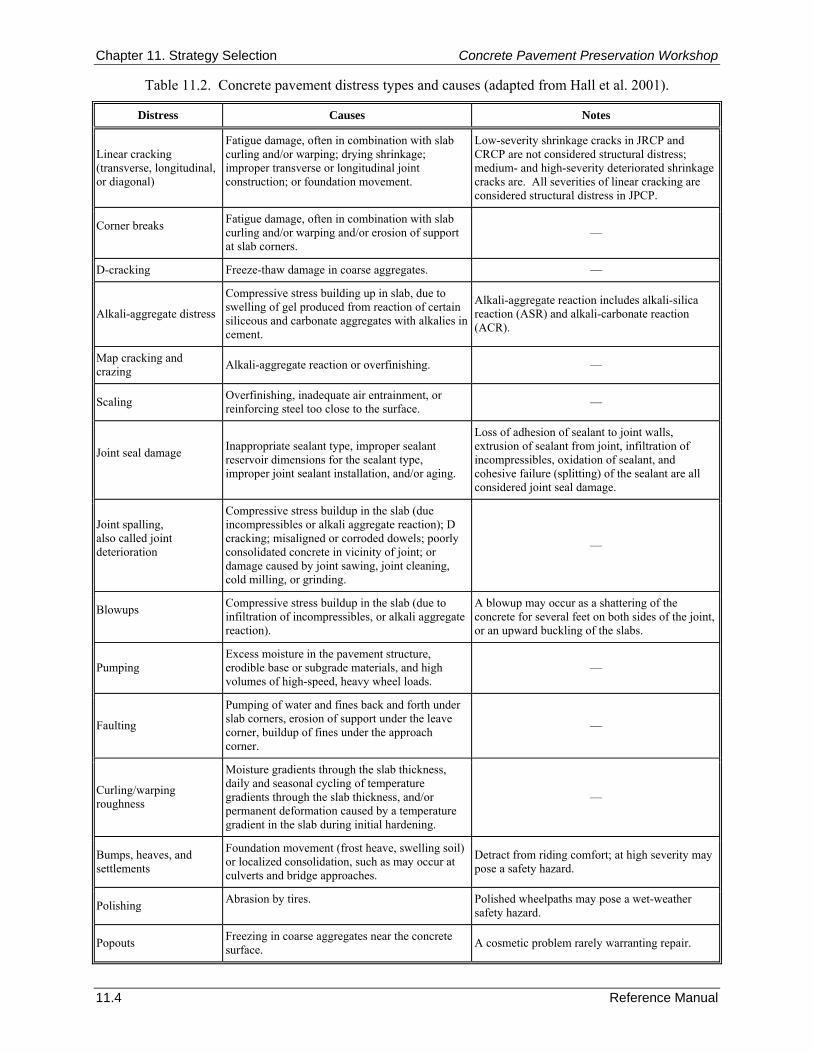
Chapter 11. Strategy Selection Concrete Pavement Preservation Workshop
11.4 Reference Manual
Table 11.2. Concrete pavement distress types and causes (adapted from Hall et al. 2001).
Distress Causes Notes
Linear cracking (transverse, longitudinal, or diagonal)
Fatigue damage, often in combination with slab curling and/or warping; drying shrinkage; improper transverse or longitudinal joint construction; or foundation movement.
Low-severity shrinkage cracks in JRCP and CRCP are not considered structural distress; medium- and high-severity deteriorated shrinkage cracks are. All severities of linear cracking are considered structural distress in JPCP.
Corner breaks
Fatigue damage, often in combination with slab curling and/or warping and/or erosion of support at slab corners.
—
D-cracking Freeze-thaw damage in coarse aggregates. —
Alkali-aggregate distress
Compressive stress building up in slab, due to swelling of gel produced from reaction of certain siliceous and carbonate aggregates with alkalies in cement.
Alkali-aggregate reaction includes alkali-silica reaction (ASR) and alkali-carbonate reaction (ACR).
Map cracking and crazing Alkali-aggregate reaction or overfinishing. —
Scaling Overfinishing, inadequate air entrainment, or reinforcing steel too close to the surface. —
Joint seal damage
Inappropriate sealant type, improper sealant reservoir dimensions for the sealant type, improper joint sealant installation, and/or aging.
Loss of adhesion of sealant to joint walls, extrusion of sealant from joint, infiltration of incompressibles, oxidation of sealant, and cohesive failure (splitting) of the sealant are all considered joint seal damage.
Joint spalling, also called joint deterioration
Compressive stress buildup in the slab (due incompressibles or alkali aggregate reaction); D cracking; misaligned or corroded dowels; poorly consolidated concrete in vicinity of joint; or damage caused by joint sawing, joint cleaning, cold milling, or grinding.
—
Blowups
Compressive stress buildup in the slab (due to infiltration of incompressibles, or alkali aggregate reaction).
A blowup may occur as a shattering of the concrete for several feet on both sides of the joint, or an upward buckling of the slabs.
Pumping Excess moisture in the pavement structure, erodible base or subgrade materials, and high volumes of high-speed, heavy wheel loads.
—
Faulting
Pumping of water and fines back and forth under slab corners, erosion of support under the leave corner, buildup of fines under the approach corner.
—
Curling/warping roughness
Moisture gradients through the slab thickness, daily and seasonal cycling of temperature gradients through the slab thickness, and/or permanent deformation caused by a temperature gradient in the slab during initial hardening.
—
Bumps, heaves, and settlements
Foundation movement (frost heave, swelling soil) or localized consolidation, such as may occur at culverts and bridge approaches.
Detract from riding comfort; at high severity may pose a safety hazard.
Polishing Abrasion by tires.
Polished wheelpaths may pose a wet-weather safety hazard.
Popouts Freezing in coarse aggregates near the concrete surface. A cosmetic problem rarely warranting repair.
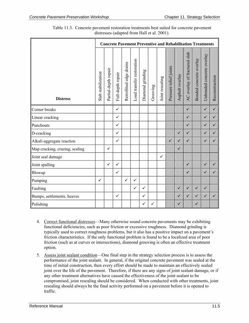
Concrete Pavement Preservation Workshop Chapter 11. Strategy Selection
Reference Manual 11.5
Table 11.3. Concrete pavement restoration treatments best suited for concrete pavement distresses (adapted from Hall et al. 2001).
Concrete Pavement Preventive and Rehabilitation Treatments
Distress Slab
stab
iliza
tion
Parti
al-d
epth
repa
ir
Full-
dept
h re
pair
Ret
rofit
ted
edge
dra
ins
Load
tran
sfer
rest
orat
ion
Dia
mon
d gr
indi
ng
Gro
ovin
g
Join
t res
ealin
g
Pres
sure
relie
f joi
nts
Asp
halt
over
lay
AC
ove
rlay
of fr
actu
red
slab
Bon
ded
conc
rete
ove
rlay
Unb
onde
d co
ncre
te o
verla
y
Rec
onst
ruct
ion
Corner breaks
Linear cracking
Punchouts
D-cracking
Alkali-aggregate reaction
Map cracking, crazing, scaling
Joint seal damage
Joint spalling
Blowup
Pumping
Faulting
Bumps, settlements, heaves
Polishing
4. Correct functional distresses—Many otherwise sound concrete pavements may be exhibiting functional deficiencies, such as poor friction or excessive roughness. Diamond grinding is typically used to correct roughness problems, but it also has a positive impact on a pavement’s friction characteristics. If the only functional problem is found to be a localized area of poor friction (such as at curves or intersections), diamond grooving is often an effective treatment option.
5. Assess joint sealant condition—One final step in the strategy selection process is to assess the performance of the joint sealant. In general, if the original concrete pavement was sealed at the time of initial construction, then every effort should be made to maintain an effectively sealed joint over the life of the pavement. Therefore, if there are any signs of joint sealant damage, or if any other treatment alternatives have caused the effectiveness of the joint sealant to be compromised, joint resealing should be considered. When conducted with other treatments, joint resealing should always be the final activity performed on a pavement before it is opened to traffic.
Chapter 11. Strategy Selection Concrete Pavement Preservation Workshop
11.6 Reference Manual
Step 4. Identify Constraints and Key Selection Factors After compiling a list of possible effective treatments under step 3, before proceeding further in the treatment selection process it is important to check those possible effective treatments against a list of any project-specific constraints or other key selection factors that may come into play. Some of the potential factors that an agency will need to consider when determining whether or not a possible treatment is feasible for a specific project are the following (AASHTO 1993; Hall et al. 2001):
Available funding.
Future maintenance requirements.
Geometric restrictions.
Lane closure time.
Environmental impact (e.g., contamination generated during construction work).
Conservation of natural resources.
Agency’s experience with the use of the treatment.
Traffic safety during construction.
Worker safety during construction.
Contractors’ experience with the treatment.
Availability of needed equipment and materials.
Competition amount providers of materials.
Stimulation of local industry.
Agency policies.
Political concerns. Because the treatments included in the scope of this course are more preventive in nature, it is envisioned that most of these potential constraints will not be an issue when selecting treatments. However, it is important that all outside constraining factors be identified at this point of the selection process to avoid conducting unnecessary work in the upcoming steps. Step 5. Develop Feasible Treatment Strategies A treatment strategy is a plan that defines what treatments to apply and when to apply them, over a selected time period. For example, a strategy using only one treatment could be to conduct diamond grinding every 8 to 10 years for the next 25 years. Another strategy could be to conduct dowel bar retrofitting activities, followed by diamond grinding during the same construction project. It is not uncommon to concurrently conduct more than one of the concrete pavement preservation activities in a single project because the various concrete pavement preservation activities complement each other. Therefore, the purpose of this step is to:
1. Determine all of the different activities that need to be conducted to best address the pavement’s needs.
2. Determine if it is best to conduct the activities concurrently, or to apply the individual activities at different times in the future.
Each individual treatment combination or treatment timing scenario can be considered a separate treatment strategy for the pavement. While there is usually an obvious choice for the most appropriate strategy, competing strategies can be objectively compared by considering the overall the life-cycle cost associated with each.
Concrete Pavement Preservation Workshop Chapter 11. Strategy Selection
Reference Manual 11.7
Step 6. Assess the Life-Cycle Costs Associated With Treatment Strategies Because the concrete pavement preservation treatments address different pavement deficiencies, life-cycle costing techniques are not typically needed to help select appropriate strategies. However, where LCCA results do become important is when the concrete pavement preservation treatments and strategies are being considered along with more extensive rehabilitation techniques (i.e., overlays) or reconstruction. An LCCA provides an objective method of comparing the costs associated with different treatments applied at different times over the life of a pavement. These results are of particular interest to those agencies that are trying to document the benefits of using more inexpensive preventive treatment strategies that delay more expensive rehabilitation activities. This section is intended to only introduce the general concepts of a life-cycle cost analysis, with more detailed information available elsewhere (Walls and Smith 1998; Hall et al. 2001; ACPA 2002). General Concepts of an LCCA
Initial construction costs are often the factor given the greatest consideration in the treatment selection process. However, expected future costs that occur at different times over the life of the treatment must also be considered, but in order to do so they must first be converted to a common basis for comparison purposes. The techniques used to perform the conversion are based on the assumption that the value of money changes with time, due to factors such as inflation. There are a number of different techniques that are used to equate the value of costs incurred at various points in time. Most commonly, these costs are expressed in terms of either a present worth (PW) cost or an equivalent uniform annual cost (EUAC). Using the PW method, all future costs are adjusted to a PW cost using a selected discount rate. The costs incurred at any time in the future can be combined with the initial construction costs to give a total PW cost over the analysis period. More detailed descriptions of some of the major required LCCA-related inputs are the following:
Analysis period—The analysis period refers to the time over which the economic analysis is to be conducted, which is not necessarily the same as the “life” of the treatment. Suggested analysis periods for new pavement design are 20 years to 50 years for high volume roadways, and 15 years to 25 years for low volume roadways (AASHTO 1993). The FHWA recommends an analysis period of at least 35 years for all pavement projects, including new or rehabilitation (Walls and Smith 1998). As a general rule of thumb, it is suggested that the analysis period should be long enough to incorporate at least one rehabilitation activity. However, for some rehabilitation work, the analysis period will sometimes be shorter (say 10 to 20 years) depending on the future use of the facility, the need for geometric improvements, and other factors. In any event, it is important that the analysis period be the same for all rehabilitation alternatives being considered.
Timing and costs of individual CPR treatments and maintenance activities—The construction of a detailed expenditure stream diagram is useful to illustrate the timing and costs associated with the application of different treatments over the analysis period, as shown in figure 11.1. This example reflects the initial costs associated with a pavement rehabilitation project, the annual costs for routine maintenance, and additional periodic costs for activities such as seal coats or other preservation actions. If a salvage value is considered at the end of the project, it is reflected as an income that can be expected from the project at the end of the analysis period. Each of these individual cost types is discussed in more detail in the next section.
Discount rate—The discount rate is the interest rate used in calculating the present value of future costs. This value that represents the time value of money is often approximated as the difference between the commercial interest rate and inflation rate as given by the consumer price index. Historical discount rates have been in the 3 to 5 percent range (Walls and Smith 1998).
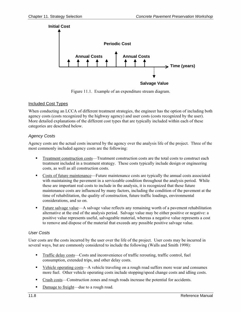
Chapter 11. Strategy Selection Concrete Pavement Preservation Workshop
11.8 Reference Manual
Initial Cost
Periodic Cost
Annual Costs Annual Costs
Salvage Value
Time (years)
Figure 11.1. Example of an expenditure stream diagram.
Included Cost Types
When conducting an LCCA of different treatment strategies, the engineer has the option of including both agency costs (costs recognized by the highway agency) and user costs (costs recognized by the user). More detailed explanations of the different cost types that are typically included within each of these categories are described below. Agency Costs
Agency costs are the actual costs incurred by the agency over the analysis life of the project. Three of the most commonly included agency costs are the following:
Treatment construction costs—Treatment construction costs are the total costs to construct each treatment included in a treatment strategy. These costs typically include design or engineering costs, as well as all construction costs.
Costs of future maintenance—Future maintenance costs are typically the annual costs associated with maintaining the pavement in a serviceable condition throughout the analysis period. While these are important real costs to include in the analysis, it is recognized that these future maintenance costs are influenced by many factors, including the condition of the pavement at the time of rehabilitation, the quality of construction, future traffic loadings, environmental considerations, and so on.
Future salvage value—A salvage value reflects any remaining worth of a pavement rehabilitation alternative at the end of the analysis period. Salvage value may be either positive or negative: a positive value represents useful, salvageable material, whereas a negative value represents a cost to remove and dispose of the material that exceeds any possible positive salvage value.
User Costs
User costs are the costs incurred by the user over the life of the project. User costs may be incurred in several ways, but are commonly considered to include the following (Walls and Smith 1998):
Traffic delay costs—Costs and inconvenience of traffic rerouting, traffic control, fuel consumption, extended trips, and other delay costs.
Vehicle operating costs—A vehicle traveling on a rough road suffers more wear and consumes more fuel. Other vehicle operating costs include stopping/speed change costs and idling costs.
Crash costs—Construction zones and rough roads increase the potential for accidents.
Damage to freight—due to a rough road.
Concrete Pavement Preservation Workshop Chapter 11. Strategy Selection
Reference Manual 11.9
The inclusion of user costs as part of a LCC analysis is a controversial issue. While there is general agreement that traffic delays and rough roads do contribute to increased costs to the user, the actual costs are difficult to quantify, particularly for road roughness. Another significant issue is that user costs are not borne by the agency, and agencies have difficult giving them the same weight in a decision process as their own actual costs. Thus traffic delay and user costs are sometimes considered as one of the criteria in the evaluation of different alternatives (as described later in this chapter), rather than being included in the cost analysis for the comparison of alternatives. The FHWA’s Interim Technical Bulletin on life-cycle costing provides an excellent summary of user costs (Walls and Smith 1998). It describes the estimation of each component of user costs (VOC, user delay costs, and crash costs) based on practices current when the report was prepared. Where there are alternate approaches available for calculating a user cost component, they are all presented. That report also devotes an entire chapter to a rational approach for the calculation of work zone user costs. Analysis Procedure
Traditionally, an LCCA is conducted by treating each of the input variables as discrete, fixed variables. This approach is known as a deterministic approach because all input values are assumed to be fixed and a single LCC result is determined. In practice, however, there is a great deal of uncertainty involved in all parts of the analysis. For example, rarely does the actual performance period of initial designs or of rehabilitation designs match exactly that which is assumed in the analysis. Furthermore, the values of unit costs can vary considerably from that which was assumed, further adding some uncertainty to the results. In recognition of the shortcomings of a deterministic approach, a probabilistic approach may be conducted that allows an agency to incorporate risk and uncertainty (Walls and Smith 1998). The analyst inputs certain variables in probabilistic terms (including expected values and standard deviations or ranges) and conducts a computer simulation that randomly samples from probabilistic descriptions of the uncertain input variables. After hundreds or thousands of iterations, the result of the analysis is a distribution showing the range of possible outcomes along with the probability of occurrence. The resulting distribution can then be analyzed statistically in order to assess acceptable levels of risks or to identify those critical factors or input variables that are driving the exposure to risk. The FHWA has produced a software program called RealCost that completely automates the LCC methodology as it applies to pavements (FHWA 2004). The software calculates life-cycle values for both agency and user costs associated with both new construction and rehabilitation activities, and can perform both deterministic and probabilistic modeling of pavement cost analysis problems. While RealCost compares the agency and user life-cycle costs of alternatives, its analysis outputs alone do not identify which alternative is the best choice for implementing a project. The lowest life-cycle cost option may not be implemented when other considerations such as risk, available budgets, and political and environmental concerns are taken into account. Step 7. Select Preferred Strategy A detailed LCCA can be one part of the decision-making process, but by itself does not necessarily identify the most optimal alternative. The lowest life-cycle cost option may not be practical when other considerations, such as available budges, network priorities, or environmental factors are taken into account. In many cases, some of the selection factors and constraints identified in step 4 may over-ride the results of the LCCA. Ultimately, the goal is to select the preferred alternative that best addresses the needs of the pavement while meeting all functional and monetary constraints that exist.
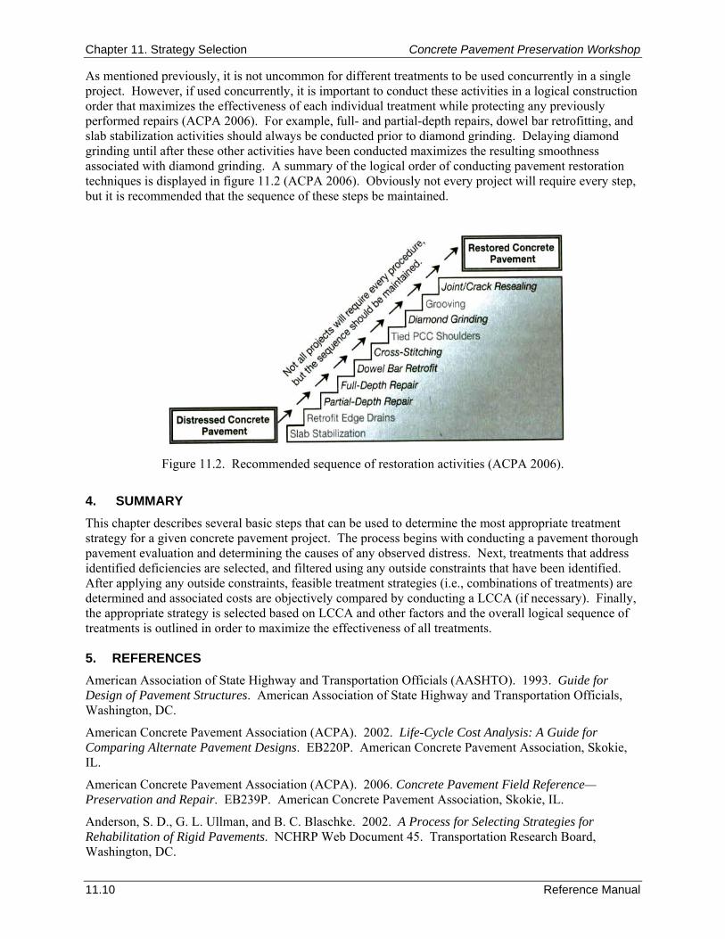
Chapter 11. Strategy Selection Concrete Pavement Preservation Workshop
11.10 Reference Manual
As mentioned previously, it is not uncommon for different treatments to be used concurrently in a single project. However, if used concurrently, it is important to conduct these activities in a logical construction order that maximizes the effectiveness of each individual treatment while protecting any previously performed repairs (ACPA 2006). For example, full- and partial-depth repairs, dowel bar retrofitting, and slab stabilization activities should always be conducted prior to diamond grinding. Delaying diamond grinding until after these other activities have been conducted maximizes the resulting smoothness associated with diamond grinding. A summary of the logical order of conducting pavement restoration techniques is displayed in figure 11.2 (ACPA 2006). Obviously not every project will require every step, but it is recommended that the sequence of these steps be maintained.
Figure 11.2. Recommended sequence of restoration activities (ACPA 2006).
4. SUMMARY This chapter describes several basic steps that can be used to determine the most appropriate treatment strategy for a given concrete pavement project. The process begins with conducting a pavement thorough pavement evaluation and determining the causes of any observed distress. Next, treatments that address identified deficiencies are selected, and filtered using any outside constraints that have been identified. After applying any outside constraints, feasible treatment strategies (i.e., combinations of treatments) are determined and associated costs are objectively compared by conducting a LCCA (if necessary). Finally, the appropriate strategy is selected based on LCCA and other factors and the overall logical sequence of treatments is outlined in order to maximize the effectiveness of all treatments. 5. REFERENCES American Association of State Highway and Transportation Officials (AASHTO). 1993. Guide for Design of Pavement Structures. American Association of State Highway and Transportation Officials, Washington, DC.
American Concrete Pavement Association (ACPA). 2002. Life-Cycle Cost Analysis: A Guide for Comparing Alternate Pavement Designs. EB220P. American Concrete Pavement Association, Skokie, IL.
American Concrete Pavement Association (ACPA). 2006. Concrete Pavement Field Reference—Preservation and Repair. EB239P. American Concrete Pavement Association, Skokie, IL.
Anderson, S. D., G. L. Ullman, and B. C. Blaschke. 2002. A Process for Selecting Strategies for Rehabilitation of Rigid Pavements. NCHRP Web Document 45. Transportation Research Board, Washington, DC.

Concrete Pavement Preservation Workshop Chapter 11. Strategy Selection
Reference Manual 11.11
Federal Highway Administration (FHWA). 2004. Life-Cycle Cost Analysis: RealCost User Manual. RealCost Version 2.1. Federal Highway Administration, Washington, DC.
Hall, K. T., C. E. Correa, S. H. Carpenter, and R. P. Elliott. 2001. Rehabilitation Strategies for Highway Pavements. NCHRP Web Document 35. Transportation Research Board, Washington, DC.
National Cooperative Highway Research Program (NCHRP). 2004. Guide for Mechanistic-Empirical Design of New and Rehabilitated Pavement Structures. Final Report, Part 3. Design Analysis. Transportation Research Board, Washington, DC.
Walls, J. and M. R. Smith. 1998. Life-Cycle Cost Analysis in Pavement Design—Interim Technical Bulletin. FHWA-SA-98-079. Federal Highway Administration, Washington, DC.

Chapter 11. Strategy Selection Concrete Pavement Preservation Workshop
11.12 Reference Manual
NOTES


February 2008
Iowa State University does not discriminate on the basis of race, color, age, religion, national origin, sexual orientation, sex, marital status, disability, or status as a veteran.
The sponsors of the center are not responsible for the accuracy of the information presented herein. The conclusions expressed in this publication are not necessarily those of the sponsors.
Iowa State University’s Center for Transportation Research and Education (CTRE) is the umbrella organization for the following centers and programs:
AuroraBridge Engineering CenterConstruction Management & TechnologyIowa Local Technical Assistance ProgramIowa Traffic Safety Data ServiceMidwest Transportation ConsortiumNational Concrete Pavement Technology CenterPartnership for Geotechnical AdvancementRoadway Infrastructure Management SystemsStatewide Urban Designs and SpecificationsSustainable Transportation Systems Program