Embed Size (px)
Citation preview

Cable glandsFor general industry and hazardous areas
February 2017

IntroductionWhen safety matters, there is only one choice
The Nicote and Kopex range of cable glands come to ABB through the acquisition of Thomas & Betts, a global leader in the design, manufacture of electrical installation products. Today, these brands are known for high quality and reliability in the industry delivering a comprehensive range of products to ensure enclosure ingress protection and cable strain-relief even in harsh environments.
Take a look at just some of the features that make Nicote the first choice:
Highly durable nickel platingThese glands are coated in a proprietary 2 coat plating process that ensures all metal components will not degrade and potentially let you down over time.
Comprehensive rangeThe greater the range of cable sizes a gland is designed to cover, the higher the risk of seals failing. ABB delivers contains a comprehensive range with smaller cable acceptance increments that also allows the gland bodies to be smaller and hence easier to use when space is tight.
Full approvalsDon’t just take our word for it, independent test bodies have confirmed that the gland range complies with relevant IEC and Australian standards including approvals for hazardous areas.
Neoprene sealsAll glands use high quality neoprene seals that retain their tension and are resistant to oil, chemicals and flame making them the best choice for hazardous applications.
IP66/68 protectionAll glands classified for indoor or outdoor use are supplied with IP66/68 gaskets for installation on the mounting thread and neoprene seals on the cable sheath. This level of protection means that the glands are protected from the ingress of dust and water. Anything less is unacceptable and compromises safety.
O’ring sealsAll glands designed for SWA cable and classified for indoor or outdoor use, feature o’ring seals between the body and sleeve to ensure that water cannot progress along the thread and compromise the seal. Just another safety feature.
Easy to useThe ability to easily produce a tight seal and correct earth everytime is of primary importance. All glands are designed to be easy to use and to ensure that the installer can see that the correct fitting instructions have been followed. For example, all SWA flameproof glands feature a loose clamping cone so that the installer can see that the armour is fully secured.

ABB | Cable glands 1
NG cable glandGeneral purpose nylon cable glands
Locknut Washer Body Claw Seals Nut
Acr
oss
corn
ers
Cab
leov
eral
lm
axim
um
Mou
ntin
gth
read
Threadlength
Catalogue no.
Mounting thread (mm) Cable acceptance details – overall diameter (mm) Cable gland (mm)
Pack quantitySize Length Minimum Maximum Across corners
NG-12 M12 x 1.5 15 4 7 15 50
NG-16 M16 x 1.5 15 6 10 22 50
NG-20 M20 x 1.5 15 8.5 14 27 25
NG-20-2.5TPS M20 x 1.5 15 2.5mm TPS N/A 27 25
NG-25 M25 x 1.5 15 12.5 18 33 25
NG-32 M32 x 1.5 15 18 25 41 10
NG-40 M40 x 1.5 15 24 32 50 10
NG-50 M50 x 1.5 20 30 41 62 2
NG-63 M63 x 1.5 20 40 51 75 2
Note: Product specifications may change at any time without notice
ABB nylon cable glands are quick and easy to install with a high quality gripping claw/seal arrangement that caters for a wide range of cable sizes per fitting. Each gland has no loose parts and requires no disassembly for cable installation.
Applications Indoor and outdoor use
Standards AS60529-2004
Function Provides seal on cable sheath
Protection class IP68, resistant to salt water, weak alcohol, oil, grease and common solvents
Construction Body - UL approved nylon 66 (black)
Seal - EPDM rubber
Thread Type Metric with locknut and IP68 washer

2 Cable glands | ABB
Mou
ntin
g th
read
Acr
oss
corn
ers
Cab
le o
vera
ll
max
imum
Body
IP66/68 gasket Neoprene seal
Skid washer
Nut
ProtrusionThreadlength
UN cable glandGeneral purpose cable gland for circular cable
Fitting instructions1 To comply with IP66/68 approvals, the fibre gasket must be installed on the mounting thread.
2 Screw the gland body into the apparatus, or use a locknut to secure body.
3 Pass the cable through the gland to the required position and tighten gland nut so that the seal grips firmly onto the cable.
Catalogue no.
Mounting thread (mm) Cable acceptance details – overall diameter (mm) Cable gland (mm)
Size Length Minimum Maximum Across corners Protrusion
UN12A 1/2” x 26 TPI 10 1.0 6.0 18.3 13
UN16A M16 x 1.5 10 1.0 6.0 20.6 13
UN20A M20 x 1.5 10 6.0 10.6 27.5 14
UN20B M20 x 1.5 10 10.6 15.0 30.9 16
UN25A M25 x 1.5 10 15.0 20.0 33.0 17
UN32A M32 x 1.5 10 20.0 25.0 40.7 18
UN40A M40 x 1.5 16 25.0 30.0 51.1 21
UN40B M40 x 1.5 16 30.0 35.0 55.0 23
UN50A M50 x 1.5 16 35.0 40.0 60.9 23
UN50B M50 x 1.5 16 40.0 45.0 67.0 24
UN63A M63 x 1.5 19 45.0 50.0 78.0 25
UN63B M63 x 1.5 19 50.0 55.0 88.0 32
Note: Product specifications may change at any time without notice
Applications Indoor and outdoor use
Standards AS60529-2004
Function Provides seal on cable sheath
Protection class Ingress of water
IP66/68 (30m)
Construction Nickel plated brass components

ABB | Cable glands 3
Protrusion
Cab
le o
vera
llm
axim
um
Acr
oss
corn
ers
Mou
ntin
g th
read
Cab
leO
/bed
ding
max
imum
BodySWA
exposed Clamp Sleeve
Threadlength
Catalogue no.
Mounting thread (mm) Cable acceptance details (mm) Cable gland (mm)SWA exposed (mm)
Inner carton pack quantitySize Length
O/bedding Overall diameter
SWA diameter Across corners ProtrusionMaximum Minimum Maximum
GN164 M16 x 1.5 10.00 7.20 7.40 10.80 0.90 - 1.25 20.5 21.5 8.0 30
GN204 M20 x 1.5 10.00 11.00 10.40 17.00 0.90 - 1.25 25.2 26.3 8.0 20
GN206 M20 x 1.5 10.00 13.75 16.60 20.00 0.90 - 1.25 27.5 26.3 8.0 20
GN254 M25 x 1.5 10.00 16.25 19.60 22.50 0.90 - 1.25 30.3 26.3 8.0 16
GN256 M25 x 1.5 10.00 18.75 22.10 26.00 1.25 - 1.60 33.6 35.7 10.5 8
GN324 M32 x 1.5 10.00 22.75 25.60 30.00 1.25 - 1.60 39.5 38.7 12.0 6
GN326 M32 x 1.5 10.00 26.50 29.60 34.00 1.60 - 2.00 44.5 38.7 12.0 4
GN405 M40 x 1.5 15.00 32.75 33.60 41.50 1.60 - 2.00 54.2 44.6 14.0 6
GN503 M50 x 1.5 15.00 38.50 41.10 49.00 2.00 - 2.50 60.3 51.3 15.5 4
GN505 M50 x 1.5 15.00 44.45 48.60 55.50 2.00 - 2.50 66.7 54.5 15.5 4
GN636 M63 x 1.5 19.00 56.25 55.10 68.25 2.50 - 3.15 82.6 56.0 17.5 2
GN753 2.5” BSP 19.00 60.35 67.85 73.00 2.50 - 3.15 95.3 60.0 21.5 1
GN755 2.5” BSP 19.00 66.70 72.60 79.40 2.50 - 3.15 101.6 60.0 21.5 1
Note: Product specifications may change at any time without notice
GN cable glandGeneral purpose cable gland for steel wired armoured cable
Fitting instructions1 Screw the gland body into the apparatus.
2 Pass the gland sleeve over the cable before commencing to strip the outer sheath of the cable.
3 Measure the length of tails required and add about 75mm to the outer sheath and armour to this point.
4 Strip the outer sheath.
5 Cut the armour wire to the SWA exposed length in the table.
6 Pass the armour clamp over the armour.
7 Pass the armour cone over the bedding and under the armour wires.
8 Pass the bedding through the gland body.
9 Engage sleeve thread onto body thread and tighten securely.
Applications Indoor use
Function Provides armour clamp
Construction Nickel plated brass components
4 Cable glands | ABB
Mou
ntin
g th
read
Cab
leO
/bed
ding
max
imum
Cab
le o
vera
llm
axim
um
Protrusion
Body
IP66/68 gasketO ringseal Clamp
SWAexposed
Sleeve
Neoprene seal
Nut
Acr
oss
corn
ers
Threadlength
Catalogue no.
Mounting thread (mm) Cable acceptance details (mm) Cable gland (mm)
SWA exposed (mm)
Inner carton pack quantitySize Length
O/bedding Overall diameter
SWA diameter Across corners ProtrusionMaximum Minimum Maximum
WGN162 M16 x 1.5 14 6.00 8.00 9.60 0.50 - 0.90 24.1 36 8 40
WGN164 M16 x 1.5 14 7.20 9.20 10.80 0.50 - 0.90 24.1 36 8 40
WGN202 M20 x 1.5 14 8.00 10.40 12.00 0.50 - 0.90 25.3 40 9 30
WGN203 M20 x 1.5 14 9.75 11.60 15.50 0.90 - 1.25 27.5 40 9 30
WGN204 M20 x 1.5 14 11.00 15.10 17.00 0.90 - 1.25 27.5 40 9 30
WGN206 M20 x 1.5 14 13.75 16.60 20.00 0.90 - 1.25 33.0 40 9 20
WGN254 M25 x 1.5 14 16.25 19.60 22.50 0.90 - 1.25 36.4 40 9 8
WGN256 M25 x 1.5 14 18.75 22.10 26.00 1.25 - 1.60 40.7 47 11 6
WGN324 M32 x 1.5 14 22.75 25.60 30.00 1.25 - 1.60 49.8 55 12 8
WGN326 M32 x 1.5 14 26.50 29.60 34.00 1.60 - 2.00 49.8 55 12 8
WGN403 M40 x 1.5 15 28.50 33.60 37.00 1.60 - 2.00 60.9 59 13 4
WGN404 M40 x 1.5 15 30.75 36.60 39.50 1.60 - 2.00 60.9 59 13 4
WGN405 M40 x 1.5 15 32.75 39.10 41.50 1.60 - 2.00 60.9 59 13 4
WGN502 M50 x 1.5 15 35.75 41.10 45.00 2.00 - 2.50 76.0 73 14 4
WGN503 M50 x 1.5 15 38.50 44.60 49.00 2.00 - 2.50 76.0 73 14 4
WGN504 M50 x 1.5 15 41.65 48.60 53.50 2.00 - 2.50 86.5 73 14 2
WGN505 M50 x 1.5 15 44.45 53.10 55.50 2.00 - 2.50 86.5 73 14 2
WGN634 M63 x 1.5 19 48.80 55.10 60.35 2.50 - 3.15 101.9 79 15 1
WGN635 M63 x 1.5 19 52.40 59.95 63.50 2.50 - 3.15 101.9 79 15 1
WGN636 M63 x 1.5 19 56.25 63.10 68.25 2.50 - 3.15 101.9 79 15 1
WGN753 2.5” BSP 19 60.35 67.85 73.00 2.50 - 3.15 115.6 93 22 1
WGN754 2.5” BSP 19 63.50 72.60 76.20 2.50 - 3.15 115.6 93 22 1
WGN755 2.5” BSP 19 66.70 75.80 79.40 2.50 - 3.15 115.6 93 22 1
WGN10A 3” BSP 19 70.00 79.00 84.00 3.15 124.0 90 22 1
WGN10B 3” BSP 19 76.00 83.60 88.50 3.15 124.0 90 22 1
Note: – Product specifications may change at any time without notice – WGN10A - B complete with earth fixing lug of 1/2” diameter
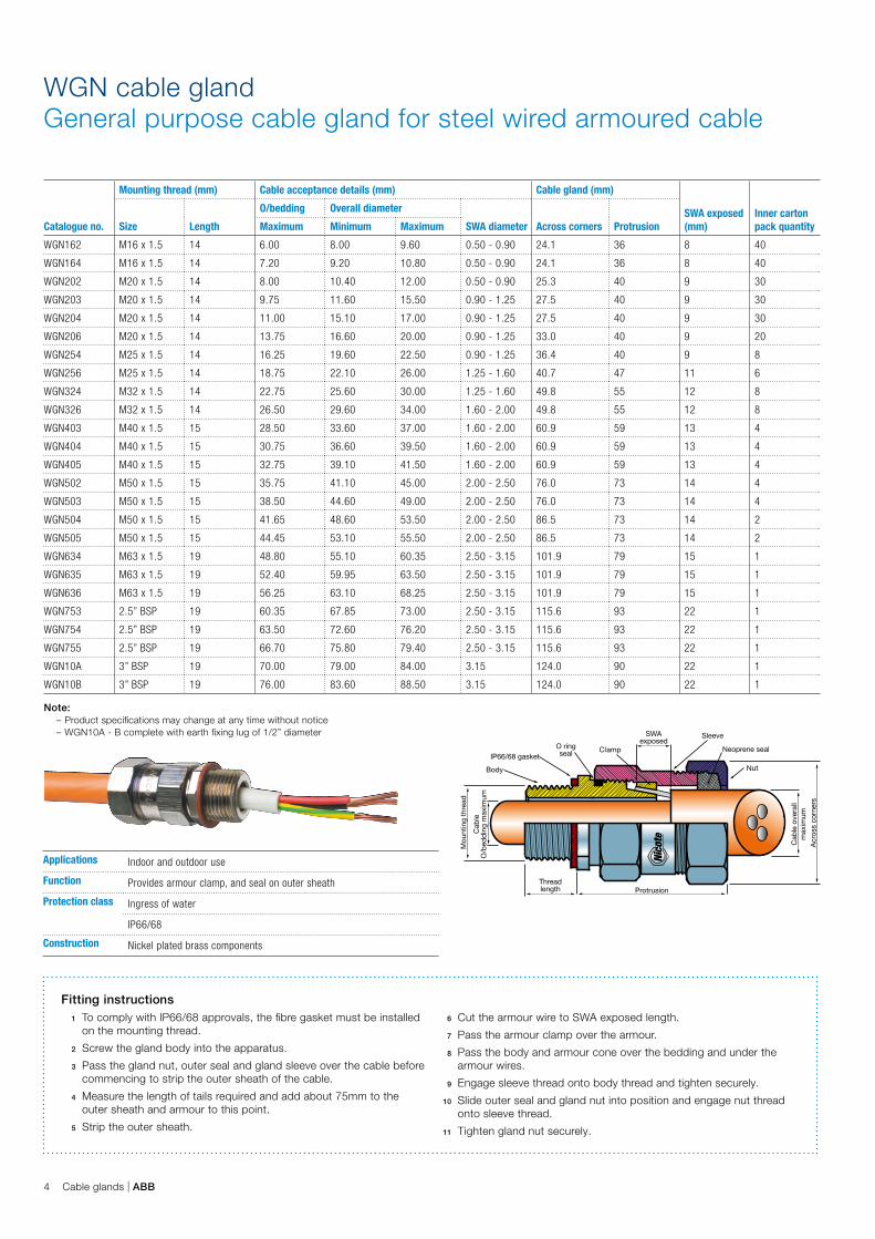
Fitting instructions1 To comply with IP66/68 approvals, the fibre gasket must be installed
on the mounting thread.
2 Screw the gland body into the apparatus.
3 Pass the gland nut, outer seal and gland sleeve over the cable before commencing to strip the outer sheath of the cable.
4 Measure the length of tails required and add about 75mm to the outer sheath and armour to this point.
5 Strip the outer sheath.
6 Cut the armour wire to SWA exposed length.
7 Pass the armour clamp over the armour.
8 Pass the body and armour cone over the bedding and under the armour wires.
9 Engage sleeve thread onto body thread and tighten securely.
10 Slide outer seal and gland nut into position and engage nut thread onto sleeve thread.
11 Tighten gland nut securely.
WGN cable glandGeneral purpose cable gland for steel wired armoured cable
Applications Indoor and outdoor use
Function Provides armour clamp, and seal on outer sheath
Protection class Ingress of water
IP66/68
Construction Nickel plated brass components

ABB | Cable glands 5
Inner neopreneseal
SWAexposed
Body
IP66/68 gasketO ringseal
Clamp
ConeSleeve
NutOuter neoprene seal
Protrusion
Acr
oss
corn
ers
Mou
ntin
g th
read
Cab
le o
vera
llm
axim
um
Cab
leO
/bed
ding
max
imum
Threadlength
Catalogue no.
Mounting thread (mm) Cable acceptance details (mm) Cable gland (mm)
SWA exposed (mm)Size Length
Overbedding Overall diameter
SWA diameter Across corners ProtrusionMinimum Maximum Minimum Maximum
FLWN202 M20 x 1.5 15.80 6.00 8.00 11.00 13.00 0.50 - 0.90 25 54 12
FLWN203 M20 x 1.5 15.80 8.30 9.75 12.50 15.50 0.90 - 1.25 27 54 12
FLWN204 M20 x 1.5 15.80 9.35 11.00 15.10 17.00 0.90 - 1.25 27 54 12
FLWN205 M20 x 1.5 15.80 10.60 12.50 16.60 20.00 0.90 - 1.25 33 54 12
FLWN206 M20 x 1.5 15.80 12.00 13.75 17.00 20.00 0.90 - 1.25 33 54 12
FLWN253 M25 x 1.5 19.00 13.35 15.00 19.60 22.50 0.90 - 1.25 36 56 12
FLWN254 M25 x 1.5 19.00 14.60 16.25 19.60 22.50 0.90 - 1.25 36 56 12
FLWN255 M25 x 1.5 19.00 15.85 17.50 22.10 26.00 1.25 - 1.60 41 56 12
FLWN256 M25 x 1.5 19.00 17.10 18.75 23.00 26.00 1.25 - 1.60 41 56 12
FLWN323 M32 x 1.5 25.40 18.35 20.75 25.60 30.00 1.25 - 1.60 50 64 13
FLWN324 M32 x 1.5 25.40 20.35 22.75 25.60 30.00 1.25 - 1.60 50 64 13
FLWN325 M32 x 1.5 25.40 22.35 24.75 29.60 34.00 1.60 - 2.00 50 64 13
FLWN326 M32 x 1.5 25.40 24.35 26.50 30.00 34.00 1.60 - 2.00 50 64 13
FLWN403 M40 x 1.5 25.40 26.10 28.50 33.60 37.00 1.60 - 2.00 61 72 15
FLWN404 M40 x 1.5 25.40 28.10 30.75 36.60 39.50 1.60 - 2.00 61 72 15
FLWN405 M40 x 1.5 25.40 30.35 32.75 37.00 41.50 1.60 - 2.00 61 72 15
Note: Product specifications may change at any time without notice
FLWN cable glandFlameproof cable gland for steel wired armoured cable
Fitting instructions1 To comply with IP66/68 approvals, the fibre gasket must be installed
on the mounting thread.
2 Screw the gland body into the apparatus.
3 Leave the inner seal in the gland body.
4 Pass the gland nut, outer seal and gland sleeve over the cable before commencing to strip the outer sheath of the cable.
5 Measure the length of tails required and add about 75mm to the outer sheath and armour to this point.
6 Strip the outer sheath.
7 Cut the armour wire to SWA exposed length.
8 Pass the armour clamp over the armour.
9 Pass the armour cone over the bedding and under the armour wires.
10 Pass the bedding through the inner seal in the gland body. Note: Unless this seal provides a push fit on the bedding the next size gland will be required. (The minimum dimension over the bedding is embossed on the sleeve of the gland for reference.) On glands over FLWN405 one or two seals are supplied with each gland, select the most suitable seal.
11 Engage sleeve thread onto body thread and tighten securely.
12 Slide outer seal and gland nut into position and engage nut thread onto sleeve thread.
13 Tighten gland nut securely.
Applications Indoor and outdoor use in hazardous areas
Standards IEC 60079 - 0:2004 IEC 61241 - 0:2004
IEC 60079 - 1:2007 IEC 61241 - 1:2004
Function Provides o/bedding flameproof seal, armour
Clamp and seal on outer sheath
Protection class ANZEx 11.2001x Ingress of water
IECEx SIM 11.0002X IP66/68 (30m)
Ex d I/IIC
Construction Nickel plated brass components

6 Cable glands | ABB
Mou
ntin
g th
read
Cab
leO
/bed
ding
max
imum
Epoxy
Protrusion
Cab
le o
vera
llm
axim
umA
cros
s co
rner
s
ClampSWA
exposedSleeve
NutOuter neoprene sealCone
Body sleeveO ringseal
IP66/68 gasketBody
Threadlength
Catalogue no.
Mounting thread (mm) Cable acceptance details (mm) Cable gland (mm)
SWA exposed (mm)
Inner carton pack quantitySize Length
O/bedding Overall diameter
SWA diameterAcross corners Protrusion Maximum Minimum Maximum
FLPW203B M20 x 1.5 15.80 9.75 12.50 15.50 0.90 - 1.25 27 54 11.5 14
FLPW206B M20 x 1.5 15.80 13.75 15.00 20.00 0.90 - 1.25 33 54 11.5 14
FLPW256B M25 x 1.5 19.00 18.75 19.50 26.00 1.25 - 1.60 41 56 11.5 10
FLPW326B M32 x 1.5 25.40 26.50 25.50 34.00 1.60 - 2.00 5 64 13.5 6
FLPW405B M40 x 1.5 25.40 32.75 33.50 41.50 1.60 - 2.00 61 72 15.5 2
FLPW503B M50 x 1.5 28.60 38.50 41.00 49.00 2.00 - 2.50 76 88 17 2
FLPW505B M50 x 1.5 28.60 44.45 48.50 55.50 2.00 - 2.50 87 88 17 2
FLPW635B M63 x 1.5 28.60 52.40 55.00 63.50 2.50 - 3.15 102 96 19 1
FLPW636B M63 x 1.5 28.60 56.25 63.00 68.00 2.50 - 3.15 102 96 19 1
FLPW754B 2.5” BSP 28.60 63.50 67.50 76.00 2.50 - 3.15 116 100 23 1
FLPW755B 2.5” BSP 28.60 66.70 75.50 79.40 2.50 - 3.15 116 100 23 1
Note: Product specifications may change at any time without notice
Gland Table 1 (mm) Table 2 (mm)
FLPW203B 11.50 13.50
FLPW206B 11.50 13.50
FLPW256B 11.50 13.50
FLPW326B 13.50 15.50
FLPW405B 15.50 17.50
FLPW503B 17.00 17.50
FLPW505B 17.00 19.50
FLPW635B 19.00 21.00
FLPW636B 19.00 21.00
FLPW754B 23.00 25.00
FLPW755B 23.00 25.00
FLPWB cable glandBarrier cable gland for steel wired armoured cable
Fitting Instructions1 To comply with IP66/68 approvals, the fibre
gasket must be installed on the mounting thread.
2 Pass nut, seal and sleeve over the outer sheath of cable (where more than 1 seal is supplied, use the seal with the smallest clearance on the cable).
3 Measure the length of cores required and strip the outer sheath and armour wires to the length shown in table 1.
4 Remove the bedding and any fillers to the length shown in table 2.
5 Slide the clamp over the armour wires and work the cone over the bedding and under the SWA.
6 Locate the body onto the cores and hold hard against the face of the cone. Screw the sleeve onto the body and tighten, now tighten the nut onto the sleeve.
7 Remove the body from the assembly.
8 Prepare the epoxy putty. This is a 2 part pack and must be mixed in a ratio of 1 to 1 until the colour is even throughout, without any streaks. After mixing it remains pliable for at least 1 hour. (see useable life for mixed epoxy on right)
9 Note: The red epoxy component is affected by storage temperature. Please check to ensure this component is as pliable as the yellow component. It is recommended that the epoxy should be mixed and fitted only with the user wearing the disposable gloves supplied with every gland.
10 Spread the conductors and apply to epoxy to the exposed centre of the conductors. Close the conductors and pack putty into the recess of the cone and down onto the top of the bedding material leaving a shoulder of putty to fill the sleeve cup. Continue folding putty round the conductors and working it well in between them, joining with that extruded from the core center avoiding any gaps or voids. Cover the conductors from the face of the cone to the length equal at least to the length of the sleeve.
11 Assemble the sleeve over the epoxy until it fits into the cone. Remove any surplus epoxy.
12 Reassemble the body, tighten and allow at least three hours for the epoxy to reach correct hardness.
13 Remove the body, fit to the equipment the reassemble completed fitting.
Useable life for mixed epoxyThis will depend upon the bulk mass and temperature. Approximate figures are:
25 grams wt 2 hours @ 25 ºC
25 grams wt 3 hours @ 15 ºC
CureThis will depend upon the bulk mass and temperature. Approximate figures are:
25 grams wt 12 hours @ 25 ºC
25 grams wt 24 hours @ 15 ºC
Mechanical properties of cured mix
Tensile strength BS6319 2 days min. 30MPa
Compressive strength BS6319 2 days min. 40MPa
Hardness min 75 shore D
Specific gravity @ 20 ºC 1.84 to 1.99
Applications Indoor and outdoor use in hazardous areas
Standards IEC 60079 - 0:2004 IEC 60079 - 1:2007
IEC 61241 - 0:2004 IEC 61241 - 1:2004
Function Provides barrier epoxy seal to cable cores, armour clamp, and seal on
outer sheath
Protection class ANZEx 11.2001X IECEx SIM 11.0002X
Ex d I//IIC Ingress of water
IP66/68 (30m)
Construction Nickel plated brass components

ABB | Cable glands 7
C2 cable glandFlameproof cable gland for circular cable
Catalogue no.Metric thread size
Cable gland dimensions (mm) Sealing ring dimensions (mm) Torque (Nm)
L L1 minimum CH (body/cap) Minimum – maximum S1+S2+S3 S1+S2 S1 S1+S2+S3 S1+S2 S1
Nickel plated brass
EXN03MMC2 M16 x 1.5 40 16 22 4,0 - 12,0 4-6 6-9 9-12 20 18 15
EXN04MMC2 M20 x 1.5 40 16 22 4,0 - 12,0 4-6 6-9 9-12 20 18 15
EXN04MLC2 M20 x 1.5 45 16 28 10,0 - 16,0 10 - 12 12 - 14,5 14,5 - 16 24 22 18
EXN05MMC2 M25 x 1.5 40 16 28 10,0 - 18,0 10 - 12 12 - 14,5 14,5 - 18 25 22 18
EXN05MLC2 M25 x 1.5 50 16 35 14,0 - 20,0 14 - 17 17 - 20 – 26 22 –
EXN06MMC2 M32 x 1.5 43 16 35 14,0 - 24,0 14 - 17 17 - 20 20 - 24 28 23 20
EXN06MLC2 M32 x 1.5 53 16 45 22,0 - 28,0 22 - 24 24 - 27 27 - 28 45 40 35
EXN07MMC2 M40 x 1.5 45 18 45 22,0 - 32,0 22 - 24 24 - 27 27 - 32 56 50 45
EXN07MLC2 M40 x 1.5 55 18 50 26,0 - 3 4,0 26 - 28 28 - 31 31 - 34 57 55 52
EXN08MSC2 M50 x 1.5 46 18 55/50 26,0 - 35,0 26 - 28 28 - 31 31 - 35 57 55 52
EXN08MMC2 M50 x 1.5 63 18 64 35,0 - 4 4,0 35 - 38 38 - 41 41 - 4 4 190 155 140
EXN09MSC2 M63 x 1.5 53 18 68/64 35,0 - 45,0 35 - 38 38 - 41 41 - 45 190 155 140
EXN09MMC2 M63 x 1.5 62 18 75/80 46,0 - 56,0 46 - 48 48 - 52 52 - 56 160 145 135
EXN10MSC2 M75 x 1.5 64 20 80 46,0 - 62,0 46 - 51 51 - 57 57 - 62 185 175 150
EXN10MMC2 M75 x 1.5 75 20 95 60,0 - 70,0 60 - 6 3 63 - 69 69 - 70 123 118 107
EXN11MSC2 M90 x 1.5 75 20 95 60,0 - 70,0 60 - 63 63 - 69 69 - 70 123 118 107
EXN11MMC2 M90 x 1.5 77 20 105 75,0 - 85,0 75 - 79 79 - 82 82 - 85 135 130 125
EXN12MSC2 M100 x 1.5 77 20 105 75,0 - 85,0 75 - 7 9 79 - 82 82 - 85 135 130 125
EXN12MMC2 M110 x 1.5 77 20 115 85,0 - 95,0 85 - 89 89 - 92 92 - 95 180 175 170
Note: – NPT thread versions also available from 3/8” to 4” sizes. Please contact sales office for more information. – * For brass version, remove N to the reference, eg. EX03MMC2 for metric / EX03AMC2 for NPT – ** For stainless steel version, add S to the reference, eg. EXS03MMC2 for metric / EXS03AMC2 for NPT – *** To purchase cable glands with locknuts, shrouds, earth tags and washers where appropriate add a K to the end of the part number, eg. EX03MMC2K
CH
Thread
L1
L
Approved to: IEC EN 60079-0, 60079-1, 60079-7, 60079-31
EC type examination certificate to: CESI 13 ATEX 041X, IECEx CES 13.0014X
Ex d IIC Gb
Ex e IIC Gb
Ex tb IIIC Db
Safe operating temperature range: -40°C to +100°C
IP test IP66-68 (5-bar 30mins)

8 Cable glands | ABB
C6 cable glandEMC shielding cable glands for circular cable
Catalogue no.Metric thread size
Cable gland dimensions (mm) Sealing ring dimensions (mm) Torque (Nm)
L L1 minimum CH (body/cap) Minimum – maximum S1+S2+S3 S1+S2 S1 S1+S2+S3 S1+S2 S1
Nickel plated brass
EXN03MSC6 M16 x 1.5 44.5 16 20 4-8 – 4-6 6-8 – 25 18
EXN03MMC6 M16 x 1.5 44.5 16 22 4-8 – 4-6 6-8 20 18 15
EXN04MMC6 M20 x 1.5 44.5 18 22 4-12 4-6 6-9 9-12 20 18 15
EXN05MMC6 M25 x 1.5 46 16 28 10-18 10-12 12-14.5 14.5-18 25 22 18
EXN06MMC6 M32 x 1.5 52 19 35 14-24 14-17 17-20 20-24 25 20 18
EXN07MMC6 M40 x 1.5 61 20 45 22-32 22-24 24-27 27-32 56 50 45
EXN08MMC6 M50 x 1.5 63.5 20 55/50 26-35 26-28 28-31 31-35 57 55 52
Note: – NPT thread versions also available from 3/8” to 1 1/2 ” sizes. Please contact sales office for more information. – * For brass version, remove N to the reference, eg. EX03MMC6 for metric / EX03AMC6 for NPT – ** For stainless steel version, add S to the reference, eg. EXS03MMC6 for metric / EXS03AMC6 for NPT – *** To purchase cable glands with locknuts, shrouds, earth tags and washers where appropriate add a K to the end of the part number, eg. EX03ASC6K
Approved to: IEC EN60079-0, 60079-1, 60079-7, 60079-31
EC type examination certificate to: CESI 13 ATEX 041X, IECEx CES 13.0014X
Ex d IIC Gb
Ex e IIC Gb
Ex tb IIIC Db
Safe operating temperature range: -40°C to +100°C
IP test IP66-68
Features – Suitable for use with EMC/shielded cables – Ex d and Ex e – Available in brass, nickel plated brass and stainless steel 316 – Large cable range within one product with removeable seals
H
L
daerhT
CH CH

Cut
line
for
min
imum
cab
ledi
amet
er
Shr
oud
num
ber
To s
uit g
land
from
sel
ectio
nch
art
Mou
ntin
g th
read
diam
eter
Ear
th b
olt
diam
eter
Across flats
Mounting thread
Cut line forminimum cable
diameter
Shroudnumber
To suit glandfrom selection
chart
Mounting thread
diameter
Earth boltdiameter
Across flats
Mounting thread
Earth tagsEarth tag - metric / materials: nickel plated brass
Catalogue no.
Diameter (mm)
A B C
EXN /M16/TAG 16.2 / 16.5 6.5 / 7.0 28.0 / 28.5
EXN /M20/TAG 20.2 / 20.5 6.5 / 7.0 28.0 / 28.5
EXN /M25/TAG 25.2 / 25.7 6.1 / 6 .6 30.5 / 31.0
EXN /M32/TAG 32.2 / 32.8 12.2 / 12.7 40.0 / 40.5
EXN /M40/TAG 40.2 / 40.7 13.0 / 13.5 45.0 / 45.5
EXN /M50/TAG 51.0 / 51.5 13.0 / 13.5 58.0 / 58.5
EXN /M63/TAG 63.7 / 6 4.2 13.0 / 13.5 65.0 / 65.5
EXN /M75/TAG 76.4 / 76.9 13.0 / 13.5 75.5 / 76.0
Locknuts
Catalogue no.Mounting thread
Across flats hexagon (mm)
Inner carton pack quantity
L12 1/2” x 26 TPI 16 100
LNB-16 M16 x 1.5 20.7 100
LNB-20 M20 x 1.5 27 100
LNB-25 M25 x 1.5 31.6 100
LNB-32 M32 x 1.5 40 100
LNB-40 M40 x 1.5 48.2 40
LNB-50 M50 x 1.5 57.3 25
LNB-63 M63 x 1.5 82 20
Shrouds
Shroud size
Cable gland
UN GN WGN FLWN FLPWB
S0 UN20AUN20B
GN204GN206GN254
WGN162WGN164WGN202
S1 UN25A GN256 WGN203WGN204
FLWN202FLWN203FLWN204
FLPW203B
S2 UN32A WGN206WGN254
FLWN205FLWN206
FLPW206B
S3 GN324GN326
WGN256 FLWN253FLWN254
S4 UN40A FLWN255FLWN256
FLPW256B
S5 UN40BUN50A
GN405 WGN324WGN326
FLWN323FLWN324FLWN325FLWN326
FLPW326B
S6 UN50BUN63A
GN503GN505
WGN403WGN404WGN405
FLWN403FLWN404FLWN405
FLPW405B
S7 UN63B GN636 WGN502WGN503
FLPW503B
Note: – Suffix -BLK for black and -ORG for orange – All glands come with gaskets but replacements available for purchase on request
Cable gland accessories
C
Earth tag
Dimensions

Contact us
© C
opyr
ight
AB
B.
9A
KK
1069
30A
3478Note: We reserve the right to make technical changes or modify
the contents of this document without prior notice. With regard to purchase orders, the agreed particulars shall prevail. ABB does not accept any responsibility whatsoever for potential errors or possible lack of information in this document.
We reserve all rights in this document and in the subject matter and illustrations contained therein. Any reproduction, disclosure to third parties or utilisation of its contents – in whole or in parts – is forbidden without prior written consent of ABB.
Copyright © 2017 ABBAll rights reserved
ABB Australia Pty LimitedFor enquiries Phone: 1800 60 20 20E-mail: [email protected]
www.abbaustralia.com.au

![ADDIMAX CABLE GLANDS FOR INDUSTRIAL USE CABLE GLANDS Glands/Cable Glands.pdf · CABLE GLANDS FOR INDUSTRIAL USE [ 7 ] Ordering Code (Gland Type / Size & Entry Thread Size), e.g. CW](https://img.pdfslide.net/doc/110x75/5f045f7d7e708231d40da7c8/addimax-cable-glands-for-industrial-use-cable-glandscable-glandspdf-cable-glands.jpg)

![ADDIMAX CABLE GLANDS FOR INDUSTRIAL USE CABLE GLANDS Glands/Cable Glands.pdf · [ 2 ] CABLE GLANDS FOR INDUSTRIAL USE Single Compression A2 Type Weatherproof & Waterproof (IP66) Cable](https://img.pdfslide.net/doc/110x75/5abe4c4f7f8b9ac0598ceed5/addimax-cable-glands-for-industrial-use-cable-glandscable-glandspdf-2-cable.jpg)