Embed Size (px)
Citation preview
Federal Aviation
Administration
Memorandum Date:
To:
From:
Prepared by:
Subject:
JUN 28L01O
All Regional Airports Division Managers
Rick Marinelli, P.E., Manager, Airport Engineering Division, AAS-IOO, x77669
Raymond Zee, P.E., Civil Engineer, Airport Engineering Division, AAS-IOO, x77874
Engineering Brief No 83: In Pavement Light Fixture Bolts
This Engineering Brief provides guidance and information for standard methods to be employed when using stainless steel hardware to secure light fixtures to L-867 and L-868 light bases. Bolt tension and clamping force are discussed, analyzed, and tested in depth to arrive at required bolt torque values. In addition, the use of ceramic-metallic fluoropolymer coated SAE Grade 2 bolts is approved.
The guidance provided includes recommendations to minimize known issues when dealing with the installation and maintenance of stainless steel hardware.
1
ENGINEERING BRIEF NO. 83
IN-PAVEMENT LIGHT FIXTURE BOLTS
I. PURPOSE
This engineering brief provides information and guidance for standard methods to be employed when using stainless steel hardware to secure light fixtures to L-867 and L-868 light bases. Bolt tension and clamping force are discussed and analyzed in depth to both test and arrive at proposed bolt torque values. In addition, the use of ceramic-metallic fluoropolymer coated SAE Grade 2 bolts is proposed and tested. II. BACKGROUND Manufacturers of light bases are currently required (per Advisory Circular (AC) 150/5345-42) to supply 18-8 stainless steel bolts with each light fixture. The use of an anti-seize compound is intended to prevent bolt thread galling and limit corrosion so that an installed bolt can be easily removed by maintenance personnel after prolonged exposure to the elements in field installations. The use of stainless steel bolts can pose unique problems when removal of the light fixture from the light base is necessary. If anti-seize compound was not applied, improperly applied, or the anti-seize used was not per manufacturer’s recommendations, bolt removal may be difficult and possibly result in bolt breakage. This is especially true for light bases that are fabricated from ASTM 240 or other stainless steel alloys. In addition, bolt removal problems can be exacerbated by the use of high speed motor drive wrenches. This Engineering Brief also introduces a coated bolt that is based upon SAE J429 Grade 2 requirements. The bolt uses a coating technology that confers both lubricity and a high level of corrosion resistance. Using this type of bolt does away with the disadvantages of using a stainless steel bolt and does not require the use of anti-seize compounds. III. APPLICATION
The Federal Aviation Administration recommends the guidelines and standards in this Engineering Brief for the use of stainless steel and coated bolts with light fixtures and light bases in field applications. This Engineering Brief provides an alternative means of compliance with required Federal Aviation Administration standards. IV. DESCRIPTION
Stainless steel bolt failure mechanisms and torque are discussed at length in this document. The use of coated SAE Grade 2 coated bolts is discussed relevant to current maintenance personnel practices and associated cost benefits.
2
V. EFFECTIVE DATES
This engineering brief shall be effective after signature by the Manager of FAA Airport Engineering Division, AAS-100. VI. APPLICABLE DOCUMENTS
FAA Advisory Circulars: AC 150/5345-46, Specification for Runway and Taxiway Light Fixtures AC 150/5340-30, The Design and Installation Details of Airport Visual Aids AC 150/5345-42, Specification for Airport Light Bases, Transformer Housings, Junction Boxes, and
Accessories Military Standards: MIL-STD-889, MILITARY STANDARD, DISSIMILAR METALS (7 JULY 1976). Society of Automotive Engineers (SAE) SAE J429, Mechanical and Material Requirements for Externally Threaded Fasteners
3
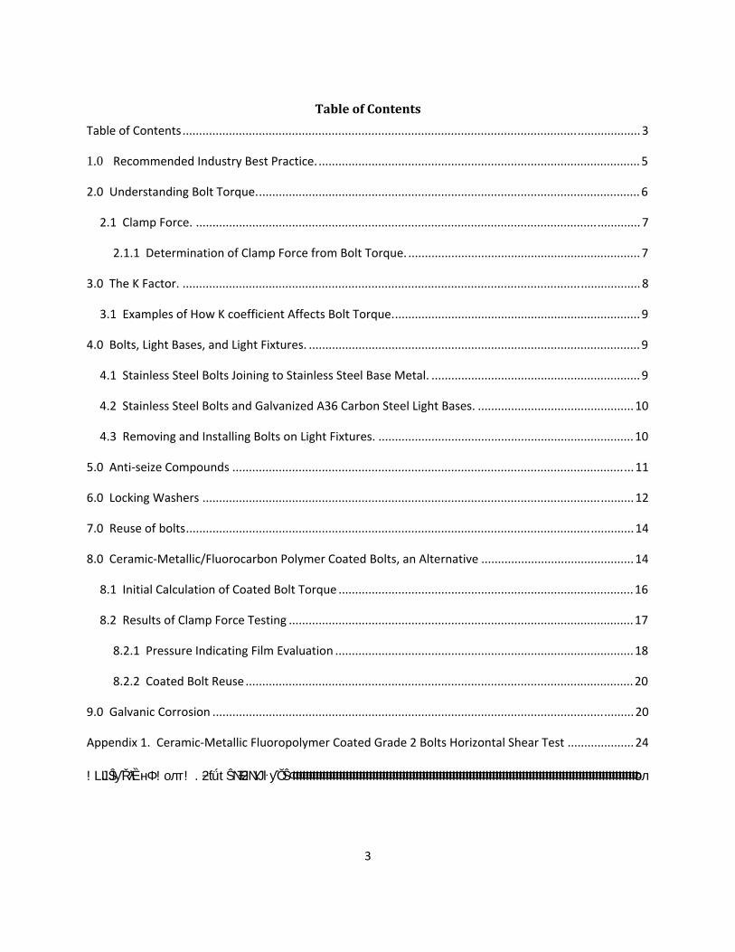
TableofContents
Table of Contents.......................................................................................................................................... 3
1.0 Recommended Industry Best Practice.................................................................................................. 5
2.0 Understanding Bolt Torque.................................................................................................................... 6
2.1 Clamp Force. ...................................................................................................................................... 7
2.1.1 Determination of Clamp Force from Bolt Torque. ...................................................................... 7
3.0 The K Factor. .......................................................................................................................................... 8
3.1 Examples of How K coefficient Affects Bolt Torque........................................................................... 9
4.0 Bolts, Light Bases, and Light Fixtures. .................................................................................................... 9
4.1 Stainless Steel Bolts Joining to Stainless Steel Base Metal. ............................................................... 9
4.2 Stainless Steel Bolts and Galvanized A36 Carbon Steel Light Bases. ...............................................10
4.3 Removing and Installing Bolts on Light Fixtures. .............................................................................10
5.0 Anti‐seize Compounds .........................................................................................................................11
6.0 Locking Washers ..................................................................................................................................12
7.0 Reuse of bolts.......................................................................................................................................14
8.0 Ceramic‐Metallic/Fluorocarbon Polymer Coated Bolts, an Alternative ..............................................14
8.1 Initial Calculation of Coated Bolt Torque .........................................................................................16
8.2 Results of Clamp Force Testing ........................................................................................................17
8.2.1 Pressure Indicating Film Evaluation ..........................................................................................18
8.2.2 Coated Bolt Reuse.....................................................................................................................20
9.0 Galvanic Corrosion ...............................................................................................................................20
Appendix 1. Ceramic‐Metallic Fluoropolymer Coated Grade 2 Bolts Horizontal Shear Test ....................24
!LJLJŜƴŘƛȄ нΦ !олт! .ƻƭǘ tŜNJŦƻNJƳŀƴŎŜΦΦΦΦΦΦΦΦΦΦΦΦΦΦΦΦΦΦΦΦΦΦΦΦΦΦΦΦΦΦΦΦΦΦΦΦΦΦΦΦΦΦΦΦΦΦΦΦΦΦΦΦΦΦΦΦΦΦΦΦΦΦΦΦΦΦΦΦΦΦΦΦΦΦΦΦΦΦΦΦΦΦΦΦΦΦΦΦΦΦΦΦΦΦΦΦΦΦΦΦΦΦΦΦол
4
TableofFigures
Figure 1. Axial Tension and Clamping Force ................................................................................................ 6
Figure 2. Example of a Dial Type Torque Wrench......................................................................................11
Figure 3. Two Part Locking Washers Installed on a 3/8‐inch Tap Bolt.......................................................13
Figure 4. Bolt With a Slightly Concave Upper Locking Washer (bolt tightened to 15 ft. lbs.) ...................13
Figure 5. Cross Section of a Fastener Coating............................................................................................15
Figure 6. An Example of a Ceramic‐Metallic/Fluoropolymer Coated 3/8‐16 X 2 Inch Bolt .......................15
Figure 7. Light Fixture Clamping Force Test Fixture...................................................................................17
Figure 8. Coated Bolt and Two Part Washers ............................................................................................18
Figure 9. Pressurex Evaluation at 120 in. lbs. and 144 in. lbs. ...................................................................19
Figure 10. Coated Bolt Reused 3 Times .....................................................................................................20
Figure 11. Stainless Steel Light Base with Aluminum Light Fixture Removed ...........................................21
Figure 12. Simplified Galvanic Table from Atlas Specialty Metals, Tech Note No. 7 .................................22
Figure 13. A36 Galvanized Light Base ‐ Aluminum Light Fixture Removed ...............................................23
Figure 14. Tinius Olsen Computerized Hydraulic Tester With Test Fixture Mounted ...............................24
Figure 15. Light Base Test Fixture ..............................................................................................................25
Figure 16. Shear Test, Direction A, Sample 1 .............................................................................................26
Figure 17. Shear Test, Direction A, Sample 2 .............................................................................................27
Figure 18. Shear Test, Direction B, Sample 1 .............................................................................................28
Figure 19. Shear Test, Direction B, Sample 2 .............................................................................................29
1.0 RecommendedIndustryBestPractice.
a. A maximum of 185 in lbs. of torque for a dry 18-8 bolt is recommended. A torque of 185 in. lbs. should not be used for a 18-8 bolt with anti-seize compound applied to the threads. With anti-seize compounds and coated bolts, less torque is required to achieve the clamping forces required to offset fixture movement in the presence of opposing forces. Always consult the light fixture manufacturer’s installation instructions for proper bolt torque. b. SAE J429 Grade 2 hex head tap bolts using a ceramic-metallic/fluoropolymer coating are highly recommended based on the evaluations performed in this engineering brief. See Appendix 1 for the recommended range of bolt torque. Do not use anti-seize or thread locking compounds with coated bolts. c. Coated bolts should be a color not currently used on the airport (example: orange or pink) for better visibility. d. Coated bolts should be monitored (recommend a 3 month inspection interval) after installation to verify corrosion resistance. Although bolt corrosion is not anticipated, the preceding will function to establish a field performance baseline. e. Although not recommended, if a non-impact type electric or air driven wrench is used, be sure to use a model that features an adjustable torque clutch. Always confirm the lowest setting does not tighten a bolt significantly beyond finger tight. Always use a high quality dial type torque wrench to perform the final bolt torque per the manufacturer's installation instructions. f. Never reuse bolts without first cleaning and inspecting them. If there is any doubt about the bolt condition, replace them and the two part locking washers. Always clean the light base upper flange threaded holes before bolt installation. Always clean the mating surfaces between the light base and the light fixture before reinstallation. All bolts should be replaced after three tightening cycles. g. If coated bolts are not used, always apply a thin layer of anti-seize to a clean and dry bolt. Do not dip the bolt in anti-seize compound. h. Always replace the two part locking washers every time the light fixture is removed from the light base. Never use a split type of locking washer. i. To preclude galvanic corrosion with stainless steel and zinc galvanized light bases, the use of fluoropolymer metallic-ceramic coated SAE J429 Grade 2 carbon steel bolts is highly recommended. The coating effectively insulates the bolt from both the zinc coating and aluminum light fixture and precludes galvanic corrosion. j. Maintain the surface flatness of light base flanges, base extensions, and spacer rings to 0.010 in. (0.254 mm) per AC 150/5345-42, Specification for Airport Light Bases, Transformer Housings, Junction Boxes, and Accessories to ensure optimum distribution of clamping forces. It is recommended that light fixture surface flatness be held to the same tolerance to avoid an uneven distribution of clamping forces.
5
2.0UnderstandingBoltTorque.
The importance of bolted connections for mating light fixtures to light bases is often overlooked. Using the proper bolt torque is crucial to ensure that the two parts are mated together so they can resist the impact forces generated by aircraft tires striking the light fixture. When a bolt is tightened to a specified torque, the bolt is subjected to a tension or preload force. The tension force slightly elongates the bolt. The more the bolt is tightened, the more the tension force or preload, and therefore the more the bolt elongates. In Figure 1, the axial tension (or preload) developed in the bolt functions to impose a clamping force between the light fixture and the light base. If the applied torque increases, then the clamping force also increases.
6
Clamp Force
Figure 1. Axial Tension and Clamping Force
If the torque continues to be increased, the bolt or the female threads in the light base will eventually fail. This is where the bolt elongation or thread deformation is sufficient to cause thread stripping or a permanent plastic deformation of the supporting structure of metal. When this point is reached, the bolt will no longer supply sufficient clamping force to secure the light fixture to the base. For a reliable connection between the light base and the light fixture, any thread stripping of either the light base flange internal threads as well as the bolt threads must be avoided. When bolts are over tightened, they also lose their ability to spring back to their original length - the bolt has a permanent "set" and cannot be reused.
Reputable bolt manufacturers will always specify both the recommended dry (no lubricants on the threads are used) torque and a proof load for a particular bolt size and metal alloy. The proof load is defined as the specified load the bolt will withstand without a permanent set.
2.1 Clamp Force. The amount of clamping force exerted by a properly tensioned fastener is normally stated to be about 75% of the proof load. For example, the proof load of an SAE J429 Grade 2 bolt is 4,250 lbs. The resulting clamp force is:
4,250 * 0.75 = 3,187.5 lbs. or approximately 3,188 lbs.
The amount of torque required to achieve this load is approximated by:
T = K*D*Fp
where:
T = bolt torque in inch pounds K = friction coefficient (dimensionless) D = nominal bolt diameter (inches) Fp = Axial clamp force (pounds)
Substituting the numbers into the equation:
T = 0.2 * 0.375 * 3,188 = 239.1 inch pounds or approximately 20 ft. lbs.
So a dry SAE Grade 2 bolt should be torqued to approximately 20 ft. lbs. to achieve a clamping force of 3,188 lbs.
2.1.1 Determination of Clamp Force from Bolt Torque. If the light fixture manufacturer’s recommended torque of 185 in. lbs. is used, the clamping force of the light fixture to the light base can be verified. Algebraically solving the equation in 2.1 for Fp and using a dry bolt (K =0.2):
NOTE: The friction coefficient K will be explained in later text.
Fp = T / K * D
Substituting the numbers:
Fp = 185 in. lbs. / 0.2 * 0.375 = 185/0.075 = 2,466 lbs. clamping force.
It then follows that the total clamping force for a light fixture to a light base is 6 times 2,466 lbs. (six bolts in the light fixture) or 14,796 lbs.
a. A quick approximate check to verify the necessary clamping force required to oppose 3,000 lbs. of force applied for the Shear Test in AC 150/5345-46:
Fp total = Opposing force (lbs.) / static friction coefficient
7
For this equation, a static friction coefficient of 0.45 was used for an aluminum surface in contact with a steel surface.
Fp total = 3,000 lbs. / 0.45 = 6,666 lbs.
Adding a safety factor of 2: 6,667 lbs. * 2 = 13, 334 lbs.
b. The approximate clamping force in a. (13,334 lbs.) is less than the result obtained with a bolt torque of 185 in. lbs. (14,796 lbs.). The light fixture should easily pass the test required in AC 150/5345-46, Chapter 4, Qualification Requirements.
NOTE: All the preceding checks by calculation are only approximations and must be verified by testing or the use of pressure indicators.
c. AC 150/5345-46 Qualification Requirements - Horizontal Shear Test.
The following information is reproduced from AC 150/5345-46:
This test simulates the shearing load applied to the top of any in-pavement fixture by a braking aircraft tire.
1. A bar must be attached (welded) to the top of the fixture so it is parallel to the runway centerline when the light is installed.
2. The ends of the bar should extend beyond the edges of the fixture to facilitate loading.
3. The light fixture, attached to a base receptacle or facsimile, and torqued to manufacturer’s specifications, must be installed in a press with the attached bar in line with the piston of the press.
4. A load of 3,000 pounds (1,360.70 kg) must be applied to the end of the bar by the press. The load must be applied and release 20 times to each end of the bar.
5. Any structural damage, movement of any part, or loosening of fasteners must be cause for rejection.
3.0TheKFactor.
K Factor is a dimensionless torque coefficient that exists between a bolt and its threaded receptacle. It is a function of the materials’ frictional characteristics, which are based on surface finish, coatings and so on. In paragraphs 2.1 and 2.1.1, the K coefficient was obtained from the bolt manufacturer’s data for a dry bolt. For all practical purposes, the use of an anti-seize compounds functions as a lubricant to lower the bolt’s frictional characteristics. It follows that if the frictional characteristics are changed, so will the amount of torque required to achieve the same clamping force be changed.
Typical ranges of K coefficient are:
0.11 for high pressure wax 0.12 to 0.16 for anti-seize compounds
8
0.20 for Plain non-plated bolts 0.25 for hot dipped galvanized bolts 0.30 and higher for rusty or corroded bolts
3.1 Examples of How K coefficient Affects Bolt Torque.
a. From paragraph 2.1, the most often used equation to approximate bolt torque is:
T = K * D * Fp T = bolt torque in inch pounds K = friction coefficient (dimensionless) D = nominal bolt diameter (inches) Fp = Axial clamp force (pounds)
b. To determine what the approximate torque that will be required for a 304 stainless steel bolt with
anti-seize compound applied: T = 0.12 * 0.375 * 2466 lbs. T= 111 in. lbs or 9.2 ft. lbs. Contrast the 9.2 ft. lbs. of torque obtained using anti-seize compound with the 20 ft. lbs. required for a dry bolt in paragraph 2.1. The reduction in applied torque to create approximately 2,466 lbs. of clamping force is due to the reduction of friction on the bolt threads. NOTE: 111 in. lbs. are only an approximate value and subject to many variables such as thread tolerances, dirt, corrosion, and operator feel. The torque value should be regarded as a starting point and confirmed by testing. Never apply a lubricant such as anti-seize compound to a bolt and torque it to the same value as a dry bolt. This will almost assure that damage to the bolts, threads, and possibly the light fixture caused by over tightening will occur. If there is any doubt about an anti-seize compound K value, call the manufacturer to verify it before installing bolts.
4.0Bolts,LightBases,andLightFixtures.
This section describes field installations of light fixtures to light bases.
4.1 Stainless Steel Bolts Joining to Stainless Steel Base Metal.
a. When using bolts made of stainless steel (SS) alloys (18-8 or 304) to secure light fixtures to light bases, the bolt performance is highly dependent upon both the installation and removal techniques employed by maintenance personnel. Improper installation techniques will result in very difficult bolt removal or breakage when light fixture removal from the light base is required. The preceding is particularly true for light fixture bases constructed of SS alloys. For example, if an anti-seize compound
9
is not applied to the bolt before threading it into an SS alloy light base upper flange, the bolt will likely gall or seize (cold weld) when removal is required.
b. The SS alloy used for the bolt self-generates an extremely thin oxide surface film (the film is the reason why a stainless steel bolt does not rust like a carbon steel bolt). When the bolt is tightened, pressure is exerted between the metal thread surfaces, and the protective oxides are subsequently wiped off. This allows the high points (also known as asperities) of the threads to make bare metal contact with each other resulting in both heat and pressure due to the contact friction between surfaces. If the pressure and heat resulting from friction is sufficiently high, plastic deformation of the metal occurs. The deformation then causes more adhesion that result in increased friction. This cumulative action eventually leads to seizing - the threads will cold weld (or seize). If tightening is continued, the fastener will eventually shear (break). The same sequence of events can occur for the removal of a bolt. When a bolt breaks within the light base flange threaded hole, removal can be both time consuming (expensive) and difficult.
c. The heat generated by the pressure of SS bolt removal (especially when partial seizing occurs) will work harden the metal. This makes drilling out a broken bolt a time consuming and difficult process that requires special drill bits and drill fixtures. Never remove stainless steel bolts at high speeds with an electric or compressed air wrench. Removal by hand guarantees that the bolt will not be heated by excessive rotation. The same applies for bolt insertion – use the lowest speed possible.
4.2 Stainless Steel Bolts and Galvanized A36 Carbon Steel Light Bases. The use of 304 SS bolts with standard ASTM A36 steel galvanized light bases has resulted in few problems other than over-torque induced failures that result in stripped/damaged light base upper flange threaded holes. This is primarily due to the difference in hardness between the two materials. ASTM A36 steel is not heat-treated and has a typical Brinell hardness of 150 - 180. 18-8 SS bolts typically have a hardness of approximately 209 to 300 on the Brinell scale. Because the bolt material is harder than the light base flange, the female threads in the flange will fail before the bolt.
Careful attention to the recommended torque values when using an anti-seize compound will reduce the incidence of light base thread damage that arises from over tightening.
4.3 Removing and Installing Bolts on Light Fixtures. Because the time allotted for maintenance personnel on the airport surface movement area is frequently limited by airline and air cargo schedules, a torque adjustable non-impact type air or electric motor driven wrench is frequently used to remove and replace multiple light fixtures. Employing this method substantially increases the risk of:
a. Stripping the bolt or threads of the light base flange because of over torque.
b. Galling when a stainless steel bolt used with a stainless steel light base is exacerbated when anti-seize compound is not or improperly used.
It is important to select a tool that uses the minimum rotational speed possible to preclude stainless steel bolt galling or seizing with SS light bases. The tool torque must be also be verified prior to using it on the airfield to prevent an over torque of the light fixture bolts. The determination of the optimal parameters
10
of both speed and applied torque for an air or electric motor driven wrench can be both time consuming and expensive.
The best and recommended method to use when removing/installing light fixture bolts with an electric or air driven wrench, whether in SS or galvanized steel light bases, is to use the lowest speed and minimum torque setting possible (lower settings on the slip clutch) where the bolt is finger tight. This should be verified with a test light fixture and base before any attempt is made in the field. The idea is to accomplish the final light fixture bolt torque with a calibrated torque wrench.
Purchase a torque wrench so that the required torque for the light fixture bolts is not at the extreme ends of the instrument’s range. This will result in more accurate torque readings. A dial type torque wrench is highly recommended because this type of torque wrench has the best and most repeatable accuracy.
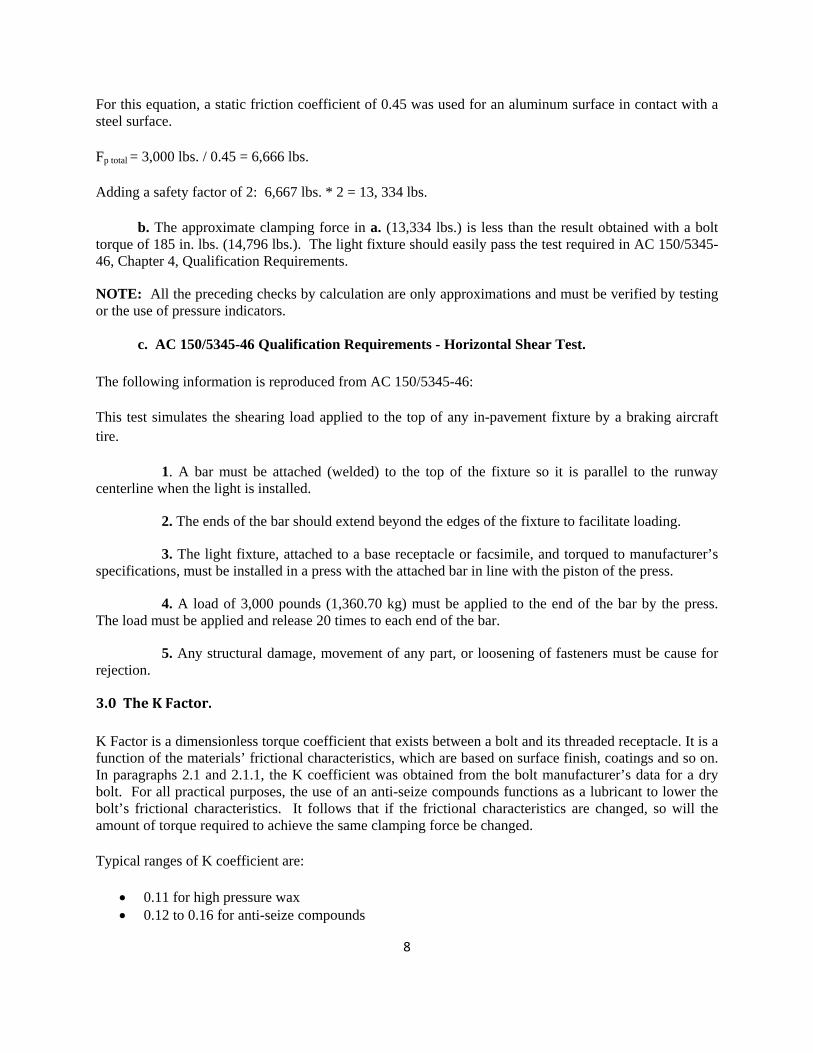
Figure 2. Example of a Dial Type Torque Wrench
Use of a quality torque wrench with an accuracy of 2% of reading from 20% of scale to full scale is recommended.
Always consult the light fixture manufacturer’s installation manual for their recommended bolt torque and anti-seize compounds. If there is any doubt about the proper torque for light fixture bolts, always call the manufacturer to verify.
5.0Anti‐seizeCompounds
Anti-seize compound is a material that most often consists of a blend of molybdenum disulfide or graphite based lubricants suspended in a wax or grease that can be used on slow moving parts to prevent seizing or galling. Some anti-seize compounds may use other metals such as nickel, but these types of compounds are primarily intended for applications where copper or aluminum may react with the application. The compound functions as a lubricant between the sliding surfaces (threads) of the bolt and light base flange threaded hole. The lubrication afforded by the use the light fixture manufacturer’s recommended anti-seize compound greatly reduces thread friction and is very effective in preventing the possibility of bolt galling or seizing. This applies for both bolt installation and removal. To be effective, an anti-seize compound should only be applied to a clean surface that is free of sand, water, or any other debris. If a bolt is to be reused, it must be thoroughly cleaned prior to the application of anti-seize compound. This will also be true for the threaded hole in the light base upper flange. Check
11
the bolt threads for damage prior to the application of the anti-seize compound. The same holds true for the threaded holes on light base flange. Threads on both the light base flange and bolt may be cleaned by a combination of compressed air (if available), wiping, brushing, and the application of a safe degreasing solvent. The use of anti-seize compound on a bolt will always reduce the amount of torque required to achieve sufficient clamping force. Never torque a bolt with anti-seize compound on it to the same torque required for a dry bolt. This is because the anti-seize compound reduces the friction (of the bolt). The dimensionless friction coefficient of a bolt is most often expressed as K (see paragraph 3 for typical K values). The light fixture manufacturer will normally furnish the proper torque values in their installation manual, with the type of anti-seize that must be used. This is because each type of anti-seize compound has a unique K value. If anti-seize compound was already purchased, be sure to obtain the K coefficient from the manufacturer. NOTE: The use of anti-seize compound by the installing contractor is recommended in AC 150/5345-42. Anti-seize compound is not supplied by light fixture or light base manufacturer. The installing contractor must use the K coefficient for the particular anti-seize compound selected (if different from the light fixture manufacturer’s recommendation) when calculating bolt torque.
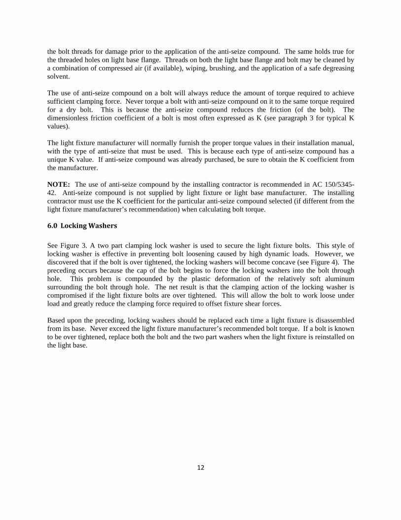
6.0LockingWashers
See Figure 3. A two part clamping lock washer is used to secure the light fixture bolts. This style of locking washer is effective in preventing bolt loosening caused by high dynamic loads. However, we discovered that if the bolt is over tightened, the locking washers will become concave (see Figure 4). The preceding occurs because the cap of the bolt begins to force the locking washers into the bolt through hole. This problem is compounded by the plastic deformation of the relatively soft aluminum surrounding the bolt through hole. The net result is that the clamping action of the locking washer is compromised if the light fixture bolts are over tightened. This will allow the bolt to work loose under load and greatly reduce the clamping force required to offset fixture shear forces. Based upon the preceding, locking washers should be replaced each time a light fixture is disassembled from its base. Never exceed the light fixture manufacturer’s recommended bolt torque. If a bolt is known to be over tightened, replace both the bolt and the two part washers when the light fixture is reinstalled on the light base.
12
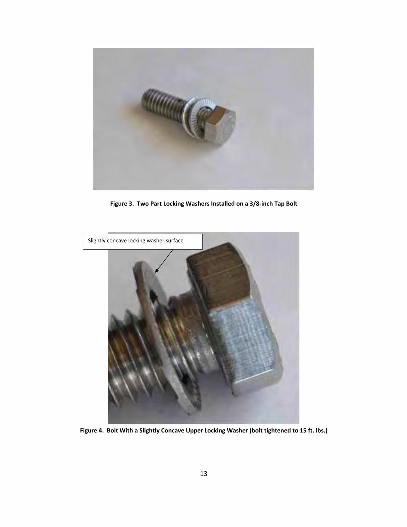
Figure 3. Two Part Locking Washers Installed on a 3/8‐inch Tap Bolt
Slightly concave locking washer surface
Figure 4. Bolt With a Slightly Concave Upper Locking Washer (bolt tightened to 15 ft. lbs.)
13
7.0Reuseofbolts
Never attempt to reuse bolts that are covered with old anti-seize compound and dirt. The same applies for the threads in the light base upper flange. Reusing dirty bolts will increase the K coefficient and result in an incorrect torque value. While the reuse of bolts is possible in consideration of the relatively low stresses encountered, there are some caveats:
Clean the bolt before inspecting it - use an absorbent rag and penetrating oil (or other safe solvent) spray to remove any old anti-seize compound/dirt from the threads. Make sure the threads are dry and free of any moisture too.
Inspect a bolt before reusing it - look for damaged threads and hex caps. Never reuse an obviously damaged or corroded bolt.
Clean and inspect the threads in the light base upper flange. Use compressed air or a solvent
spray (use safety glasses to prevent injury from any flying debris or solvent) to remove dirt prior to the reinsertion of any bolts. The same applies for water - the bolt holes must be dry.
Clean the light base and light fixture flanges before any reassembly is attempted. Check the condition of the O-ring and replace if it is damaged.
If you suspect that a bolt was over tightened, do not reuse it. Check for damaged threads on the
light base upper flange.
If light base threads are damaged, use a tap to attempt to restore them. If the threads are severely damaged and will not allow the proper torque, use an appropriate insert to repair the threaded hole.
Always reapply a thin layer of anti-seize compound with a brush or rag to a clean and dry bolt - do not dip the bolt in the anti-seize compound.
An established schedule for checking light fixture bolt torque and bolt condition is strongly
recommended. This is particularly true for areas that are subject to high impact loads from aircraft – touchdown zone lights, runway centerline lights, and taxiway lead-off lights.
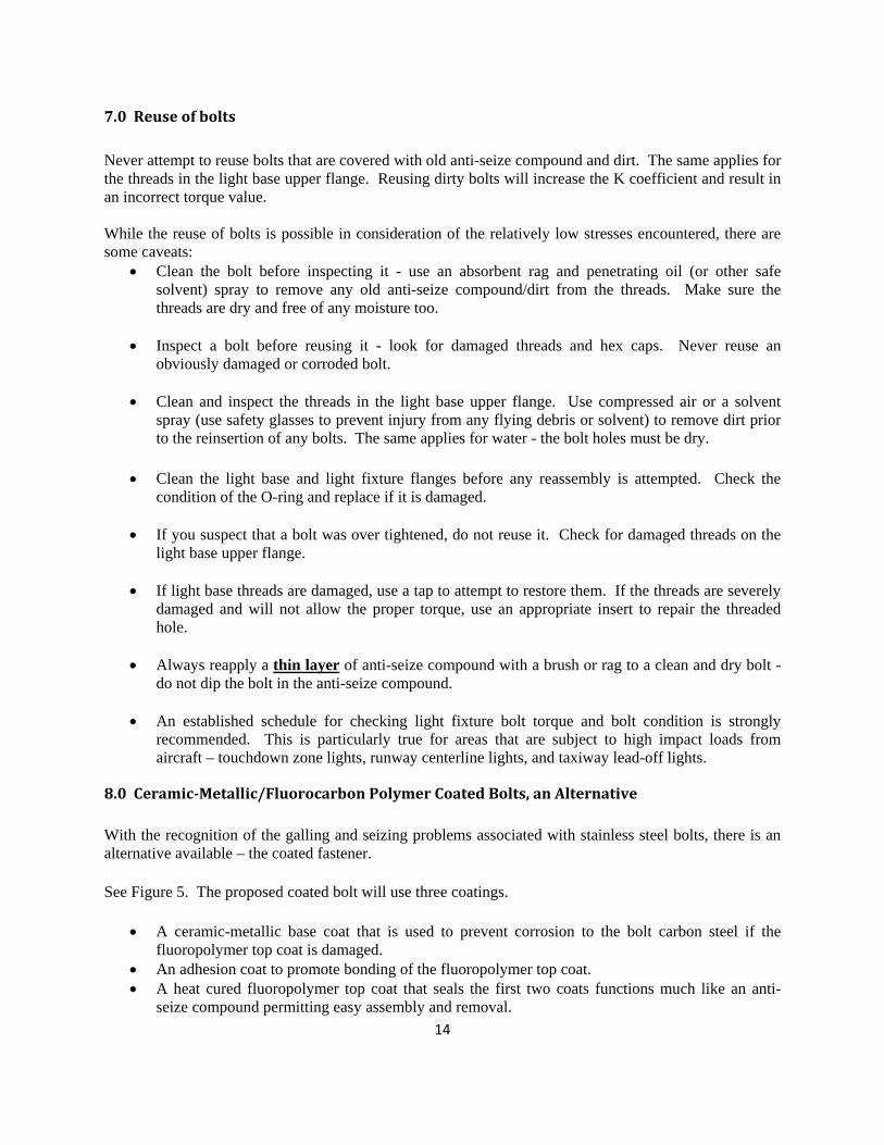
8.0Ceramic‐Metallic/FluorocarbonPolymerCoatedBolts,anAlternative
With the recognition of the galling and seizing problems associated with stainless steel bolts, there is an alternative available – the coated fastener.
See Figure 5. The proposed coated bolt will use three coatings.
A ceramic-metallic base coat that is used to prevent corrosion to the bolt carbon steel if the fluoropolymer top coat is damaged.
An adhesion coat to promote bonding of the fluoropolymer top coat. A heat cured fluoropolymer top coat that seals the first two coats functions much like an anti-
seize compound permitting easy assembly and removal.
14
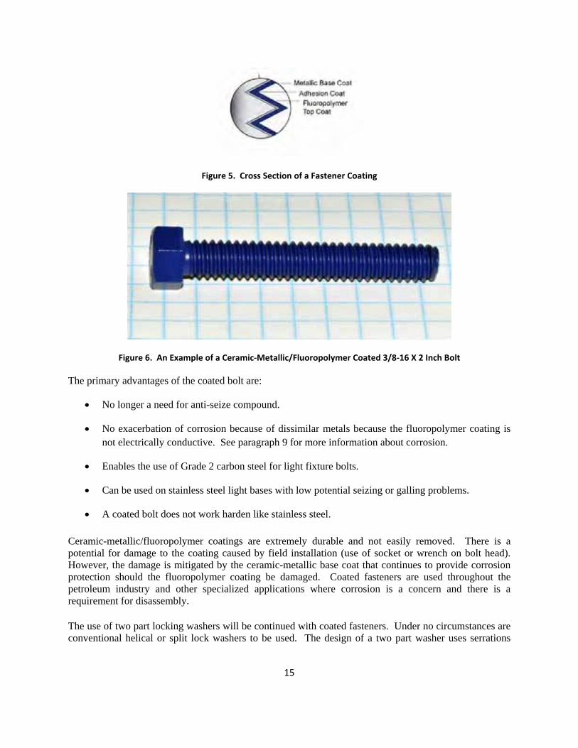
Figure 5. Cross Section of a Fastener Coating
Figure 6. An Example of a Ceramic‐Metallic/Fluoropolymer Coated 3/8‐16 X 2 Inch Bolt
The primary advantages of the coated bolt are:
No longer a need for anti-seize compound.
No exacerbation of corrosion because of dissimilar metals because the fluoropolymer coating is not electrically conductive. See paragraph 9 for more information about corrosion.
Enables the use of Grade 2 carbon steel for light fixture bolts.
Can be used on stainless steel light bases with low potential seizing or galling problems.
A coated bolt does not work harden like stainless steel.
Ceramic-metallic/fluoropolymer coatings are extremely durable and not easily removed. There is a potential for damage to the coating caused by field installation (use of socket or wrench on bolt head). However, the damage is mitigated by the ceramic-metallic base coat that continues to provide corrosion protection should the fluoropolymer coating be damaged. Coated fasteners are used throughout the petroleum industry and other specialized applications where corrosion is a concern and there is a requirement for disassembly.
The use of two part locking washers will be continued with coated fasteners. Under no circumstances are conventional helical or split lock washers to be used. The design of a two part washer uses serrations
15
where the washers contact the underside of the hex head on a bolt and the upper surface of bolt holes in the light fixture casting.
Coated bolts may be reused if they are first cleaned (wipe threads and cap with a clean shop rag) then inspected for any damage. Visible wear on the fluoropolymer outer coating is permissible and will not compromise the corrosion protection afforded by the ceramic-metallic base coat. Do not reuse fasteners that show any sign of rust under the hex head. The light base upper flange threaded holes must be cleaned before installation is attempted.
8.1 Initial Calculation of Coated Bolt Torque
The use of fluoropolymer coatings significantly affects the amount of torque required to achieve the necessary light fixture clamping force to the light base upper flange. Typical K values for these types of coatings are from 0.1 to 0.12. As a starting point, the industry standard equation for the approximation of bolt torque is solved for a nominal clamping force of 2500 lbs. between the light fixture and light base upper flange.
Torque = K * D * P
Torque = 0.1 * 0.375 * 2500 lb. = 93.75 in. lbs.
The torque value that is calculated above is only an approximation and must be regarded as a likely starting point. We rounded the calculated value to 120 in. lbs. for field applications.
16
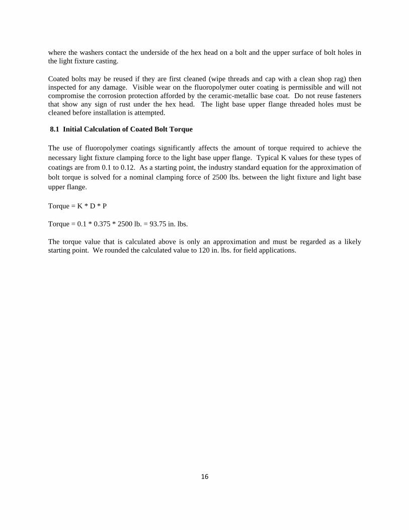
8.2 Results of Clamp Force Testing
We fabricated a test fixture for clamp force testing per Figure 7. A 5 inch galvanized steel light base extension was used with a ½-inch spacer ring. All contact surfaces were thoroughly cleaned prior to joining them.
Figure 7. Light Fixture Clamping Force Test Fixture
A pressure indicating film that indicates the distribution of clamping pressure from 1,400 to 7,100 lbs. per square inch (psi) was mounted between the base of the light fixture and the spacer ring. The degree of saturation of magenta color on the film indicates the amount of applied pressure. A color matching chart is furnished with each lot of pressure indicating film to match the indicated color with that on the calibrated chart.
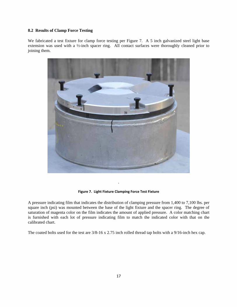
The coated bolts used for the test are 3/8-16 x 2.75 inch rolled thread tap bolts with a 9/16-inch hex cap.
17
Pressure indicating film location (white
area).
Figure 8. Coated Bolt and Two Part Washers
The bolts were simply dropped into the clearance hole and tightened to finger tight. Coated bolt installation was noticeably easier when compared with the standard SS alloy bolts. Very little pressure was required to rotate the bolt to finger tight.
Bolt torque was established at 120 in. lbs. to facilitate ease of installation in the field. Two part locking washers were used (see Figure 3). When tightening the coated bolts with a torque wrench, the bolts felt very smooth – there were no perceptible tight spots or roughness evident. Upon the completion of tightening, the torque wrench was at the 3:00 position (start at 12:00).
The assembled light fixture was allowed to remain in contact with the pressure indicating film for one hour to completely develop the pressure indications. Upon removal of the bolts, the two part lock washers had a pronounced feel of disengagement – this confirms that the locking washers are functional at 120 in. lbs. of applied torque.
The pressure indicating film was evaluated for clamping force distribution. The clamping force should be highest at areas closest to the bolt and fall off rapidly at greater than 1.5 times the bolt diameter (or approximately 0.6 inch). The light fixture was removed from the spacer ring. There was no evidence of bolt damage (thread stretch) or coating removal. This means that bolts could be used more than once if they exhibit no signs of corrosion or thread damage.
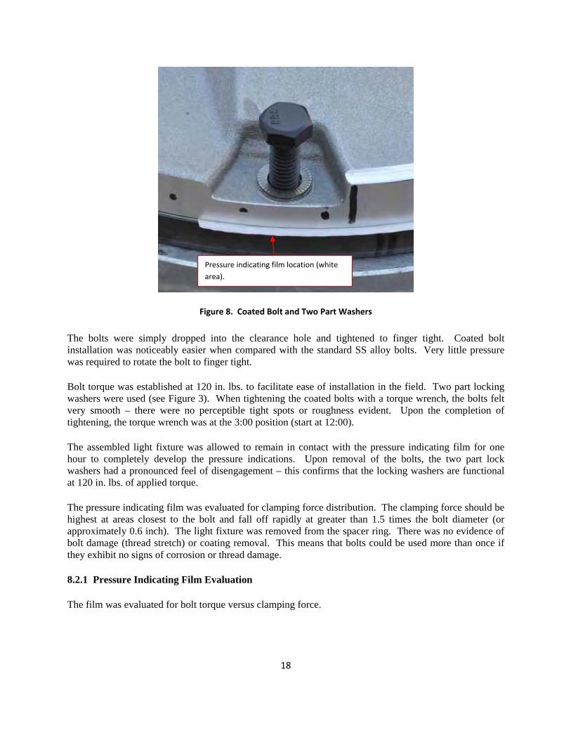
8.2.1 Pressure Indicating Film Evaluation
The film was evaluated for bolt torque versus clamping force.
18
Approximately 7000 lbs. of pressure
120 in. lbs. torque
144 in. lbs. torque
Approximately 2500 lbs. of pressure
Figure 9. Pressurex Evaluation at 120 in. lbs. and 144 in. lbs.
In Figure 9, the uppermost strip is the pressure distribution results of 144 in. lbs. of applied torque. Note how rapidly the pressure decreases with increasing distance from the bolt. The reason more pressure (dark magenta color) is exerted at the topmost outer section of the bolt hole is that the light fixture casting at this point is much thinner and allows more deflection that functions to increase pressure (see Figure 8 for a view of the light fixture casting).
Note the decrease in pressure indications in the lowermost strip of film in Figure 9 – the bolt was tightened to 120 in. lbs. of torque. Again, the same phenomenon of more pressure at the casting edges is evident because of casting thickness at the outer edge of the bolt hole.
The reason for the variation of pressure (other than light fixture casting deflection) across the flange surface is because of flange surface flatness. Using a glass surface plate, the spacer flatness variation over the entire surface was found to exceed 0.005 in. This causes high and low spots and corresponding pressure differences in the flange mating surfaces when a light fixture is bolted to the light base. If the variation is severe, an even distribution of clamping forces becomes impossible. However, if there is
19
sufficient force around bolt points, this may provide sufficient clamping force to overcome the test shear force of 3,000 lbs.
It can be concluded from the results shown in Figure 9 that 120 in. lbs. or applied bolt torque will result in sufficient clamping pressure to offset a 3,000 lb. shear force. Bolt torque should not be increased beyond 144 in. lbs. (or the light fixture manufacturer’s recommended bolt torque) because permanent distortion of the light fixture casting may occur.
8.2.2 Coated Bolt Reuse
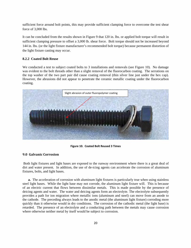
We conducted a test to subject coated bolts to 3 installations and removals (see Figure 10). No damage was evident to the bolt threads other than a slight removal of the fluorocarbon coating. The serrations on the top washer of the two part pair did cause coating removal (thin silver line just under the hex cap). However, the abrasions did not appear to penetrate the ceramic metallic coating under the fluorocarbon coating.
Slight abrasion of outer fluoropolymer coating
Figure 10. Coated Bolt Reused 3 Times
9.0GalvanicCorrosion
Both light fixtures and light bases are exposed to the runway environment where there is a great deal of dirt and water present. In addition, the use of de-icing agents can accelerate the corrosion of aluminum fixtures, bolts, and light bases.
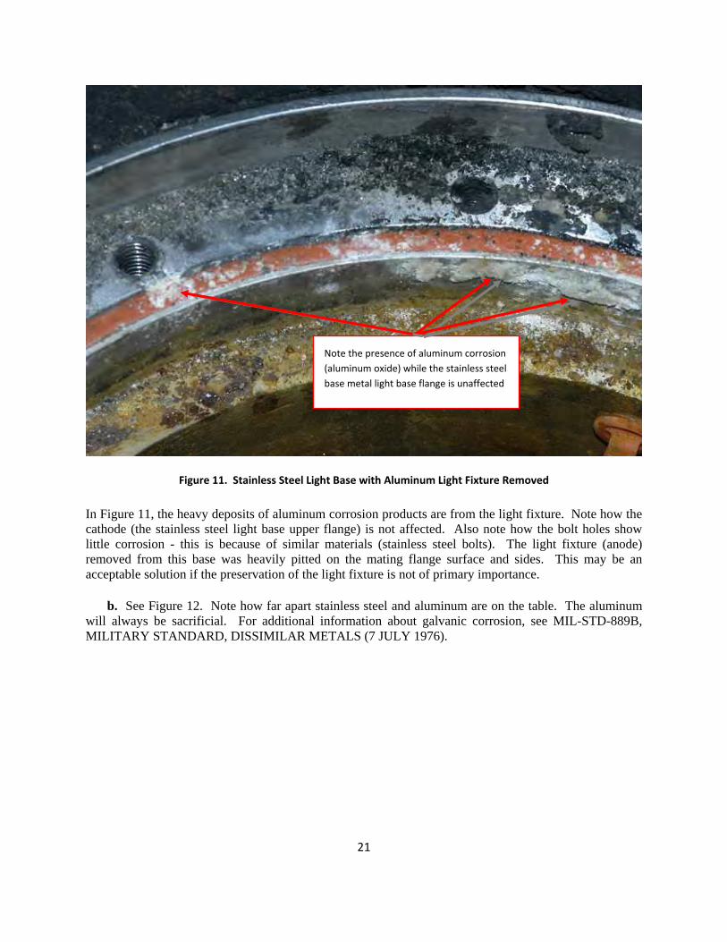
a. The acceleration of corrosion with aluminum light fixtures is particularly true when using stainless steel light bases. While the light base may not corrode, the aluminum light fixture will. This is because of an electric current that flows between dissimilar metals. This is made possible by the presence of deicing agents and water. The water and deicing agents form an electrolyte. The electrolyte subsequently provides a path for ion migration where metallic ions (aluminum and steel) can move from an anode to the cathode. The preceding always leads to the anodic metal (the aluminum light fixture) corroding more quickly than it otherwise would in dry conditions. The corrosion of the cathodic metal (the light base) is retarded. The presence of an electrolyte and a conducting path between the metals may cause corrosion where otherwise neither metal by itself would be subject to corrosion.
20
Note the presence of aluminum corrosion
(aluminum oxide) while the stainless steel
base metal light base flange is unaffected
Figure 11. Stainless Steel Light Base with Aluminum Light Fixture Removed
In Figure 11, the heavy deposits of aluminum corrosion products are from the light fixture. Note how the cathode (the stainless steel light base upper flange) is not affected. Also note how the bolt holes show little corrosion - this is because of similar materials (stainless steel bolts). The light fixture (anode) removed from this base was heavily pitted on the mating flange surface and sides. This may be an acceptable solution if the preservation of the light fixture is not of primary importance.
b. See Figure 12. Note how far apart stainless steel and aluminum are on the table. The aluminum will always be sacrificial. For additional information about galvanic corrosion, see MIL-STD-889B, MILITARY STANDARD, DISSIMILAR METALS (7 JULY 1976).
21
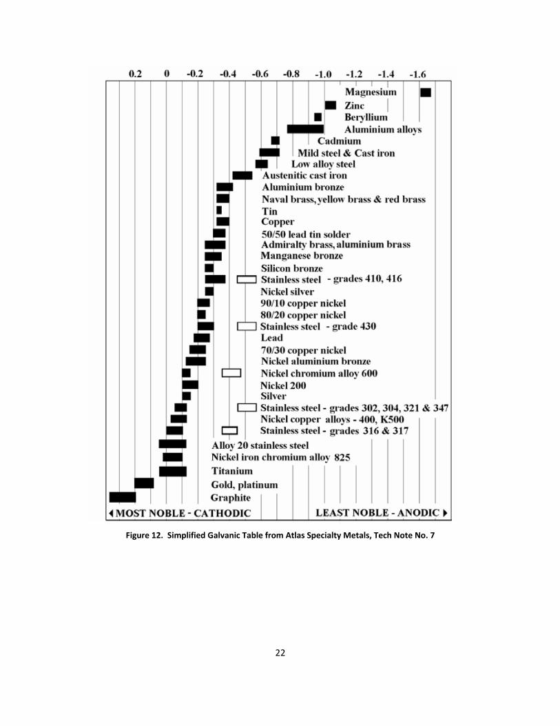
Figure 12. Simplified Galvanic Table from Atlas Specialty Metals, Tech Note No. 7
22
23
Zinc depletion areas
Figure 13. A36 Galvanized Light Base ‐ Aluminum Light Fixture Removed
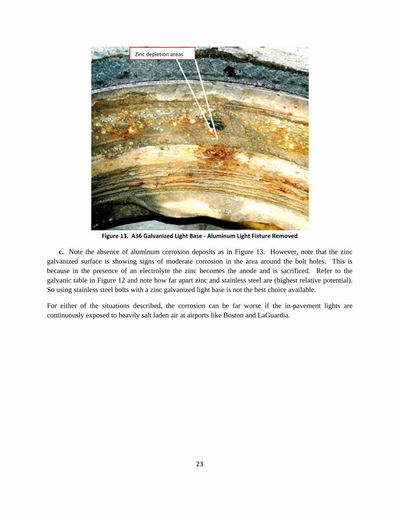
c. Note the absence of aluminum corrosion deposits as in Figure 13. However, note that the zinc galvanized surface is showing signs of moderate corrosion in the area around the bolt holes. This is because in the presence of an electrolyte the zinc becomes the anode and is sacrificed. Refer to the galvanic table in Figure 12 and note how far apart zinc and stainless steel are (highest relative potential). So using stainless steel bolts with a zinc galvanized light base is not the best choice available.
For either of the situations described, the corrosion can be far worse if the in-pavement lights are continuously exposed to heavily salt laden air at airports like Boston and LaGuardia.
Appendix1.Ceramic‐MetallicFluoropolymerCoatedGrade2BoltsHorizontalShearTest
Purpose: A horizontal shear test was conducted per the requirements in AC 150/5345-46, (see paragraph 2.1.1c for test details) by Northeast Wisconsin Technical College, Green Bay, Wisconsin on February 15, 2010. This test confirms that 120 inch pounds of torque provide sufficient clamping force to prevent any movement of the light fixture. The light fixture facsimile was subjected to 3,000 pounds of force parallel to the mounting surface.
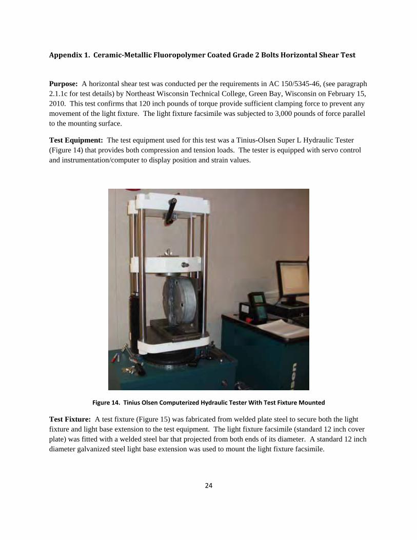
Test Equipment: The test equipment used for this test was a Tinius-Olsen Super L Hydraulic Tester (Figure 14) that provides both compression and tension loads. The tester is equipped with servo control and instrumentation/computer to display position and strain values.
Figure 14. Tinius Olsen Computerized Hydraulic Tester With Test Fixture Mounted
Test Fixture: A test fixture (Figure 15) was fabricated from welded plate steel to secure both the light fixture and light base extension to the test equipment. The light fixture facsimile (standard 12 inch cover plate) was fitted with a welded steel bar that projected from both ends of its diameter. A standard 12 inch diameter galvanized steel light base extension was used to mount the light fixture facsimile.
24
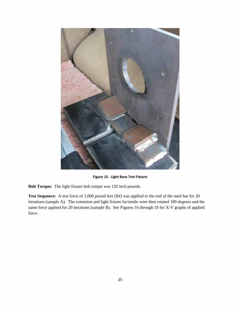
Figure 15. Light Base Test Fixture
Bolt Torque: The light fixture bolt torque was 120 inch pounds.
Test Sequence: A test force of 3,000 pound feet (lbf) was applied to the end of the steel bar for 20 iterations (sample A). The extension and light fixture facsimile were then rotated 180 degrees and the same force applied for 20 iterations (sample B). See Figures 16 through 19 for X-Y graphs of applied force.
25

Figure 16. Shear Test, Direction A, Sample 1
26
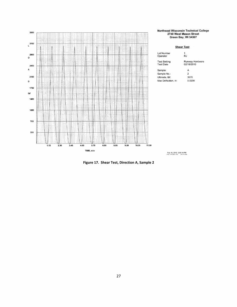
Figure 17. Shear Test, Direction A, Sample 2
27

Figure 18. Shear Test, Direction B, Sample 1
28
29
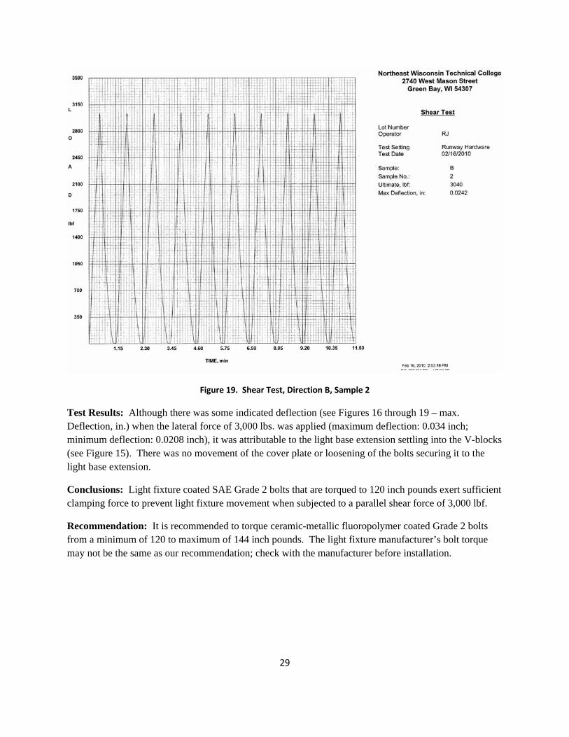
Figure 19. Shear Test, Direction B, Sample 2
Test Results: Although there was some indicated deflection (see Figures 16 through 19 – max. Deflection, in.) when the lateral force of 3,000 lbs. was applied (maximum deflection: 0.034 inch; minimum deflection: 0.0208 inch), it was attributable to the light base extension settling into the V-blocks (see Figure 15). There was no movement of the cover plate or loosening of the bolts securing it to the light base extension.
Conclusions: Light fixture coated SAE Grade 2 bolts that are torqued to 120 inch pounds exert sufficient clamping force to prevent light fixture movement when subjected to a parallel shear force of 3,000 lbf.
Recommendation: It is recommended to torque ceramic-metallic fluoropolymer coated Grade 2 bolts from a minimum of 120 to maximum of 144 inch pounds. The light fixture manufacturer’s bolt torque may not be the same as our recommendation; check with the manufacturer before installation.
30
Appendix 2. A307A Bolt Performance
Due to the long lead times required for 1022 alloy steel (this alloy is used to fabricate SAE Grade 2 bolts),
it was decided to use A36 alloy steel to form comparable ASTM A307A ceramic-metallic fluoropolymer
coated bolts. It should be noted that because the bolt threads are machined slightly undersized (0.003
inch) to accommodate the coating thickness, the bolt will not qualify to the A307A specification for
dimensions. The same is true for SAE Grade 2 bolts.
The alloy used (A36 alloy) to cold form the coated bolts is identical in performance to that used for
standard A307A bolts. This was confirmed by independently testing the wedge tensile strength of the
coated A307A equivalent bolts. The wedge tensile strength was confirmed at 61 to 69 kpsi for 5 samples
and met the ASTM A307 specification (60 kpsi minimum).
The primary difference between Grade 2 and A307A bolts is the tensile strength. 3/8 inch SAE Grade 2
bolts have a wedge tensile strength requirement of 74 kpsi minimum, while the A307A bolt has tensile
strength of 60 kpsi minumum. The difference in tensile strength between the two bolt specifications is
not considered to be problematic when bolting light fixtures to light bases - there is insufficient stress at
the torque range of 120 to 144 in. lbs. to place excessive tension loads on either type of bolt.
To prove that our conclusions were correct, we tested the A307A equivalent bolts in the same test fixture
as the SAE Grade 2 bolts in Appendix 1 at 3,000 lb. ft. We also conducted an additional test at 6,000 lb.
ft. of force parallel to the light fixture facsimile mounting surface to further prove that our clamping force
calculations were correct. The A307A equivalent bolts were torqued to 10 ft. lbs. for all tests.
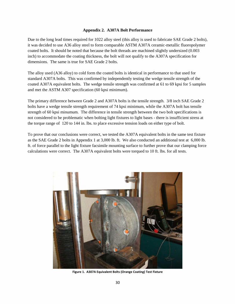
Figure 1. A307A Equivalent Bolts (Orange Coating) Test Fixture
31
Note that the light base extension in Figure 1 is seated into steel V blocks. The A307A equivalent test
bolts are the bright orange coated bolts securing the light fixture facsimile to the extension.
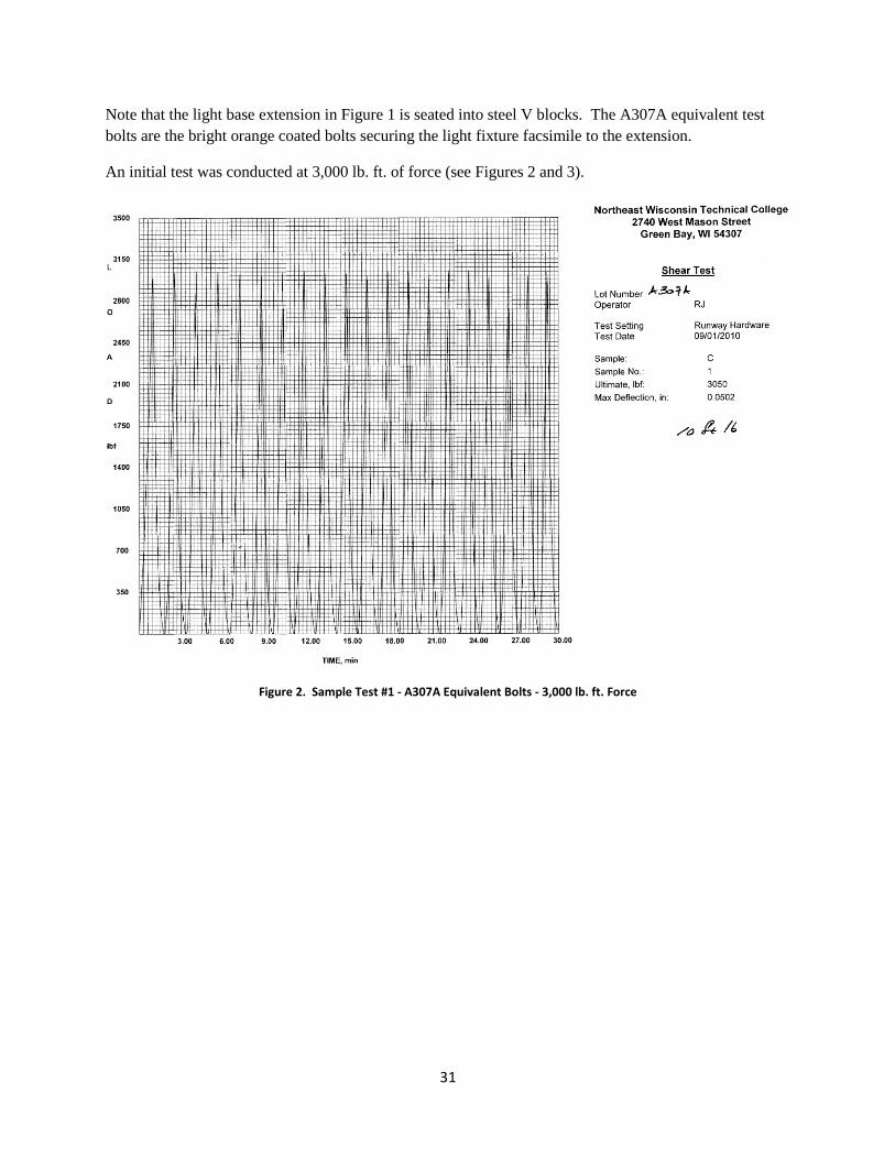
An initial test was conducted at 3,000 lb. ft. of force (see Figures 2 and 3).
Figure 2. Sample Test #1 - A307A Equivalent Bolts - 3,000 lb. ft. Force
32
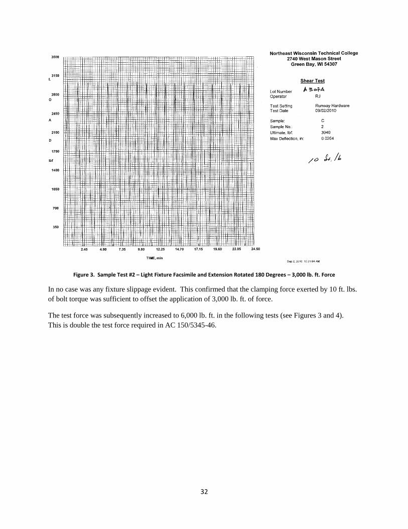
Figure 3. Sample Test #2 – Light Fixture Facsimile and Extension Rotated 180 Degrees – 3,000 lb. ft. Force
In no case was any fixture slippage evident. This confirmed that the clamping force exerted by 10 ft. lbs.
of bolt torque was sufficient to offset the application of 3,000 lb. ft. of force.
The test force was subsequently increased to 6,000 lb. ft. in the following tests (see Figures 3 and 4).
This is double the test force required in AC 150/5345-46.
33
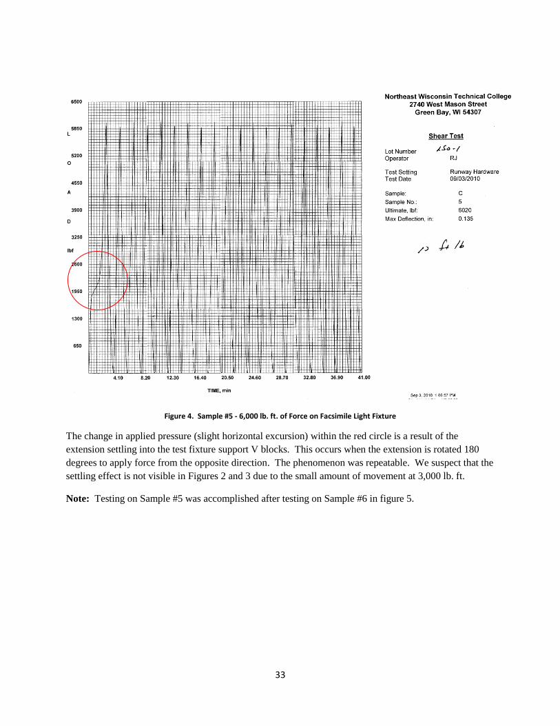
Figure 4. Sample #5 - 6,000 lb. ft. of Force on Facsimile Light Fixture
The change in applied pressure (slight horizontal excursion) within the red circle is a result of the
extension settling into the test fixture support V blocks. This occurs when the extension is rotated 180
degrees to apply force from the opposite direction. The phenomenon was repeatable. We suspect that the
settling effect is not visible in Figures 2 and 3 due to the small amount of movement at 3,000 lb. ft.
Note: Testing on Sample #5 was accomplished after testing on Sample #6 in figure 5.
34
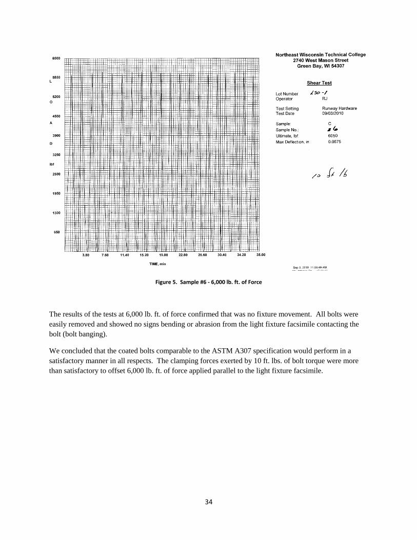
Figure 5. Sample #6 - 6,000 lb. ft. of Force
The results of the tests at 6,000 lb. ft. of force confirmed that was no fixture movement. All bolts were
easily removed and showed no signs bending or abrasion from the light fixture facsimile contacting the
bolt (bolt banging).
We concluded that the coated bolts comparable to the ASTM A307 specification would perform in a
satisfactory manner in all respects. The clamping forces exerted by 10 ft. lbs. of bolt torque were more
than satisfactory to offset 6,000 lb. ft. of force applied parallel to the light fixture facsimile.