Embed Size (px)
Citation preview
FEDERAL UNIVERSITY OYE-EKITI
FACULTY OF ENGINEERING AND TECHNOLOGY
DEPARTMENT OF CIVIL ENGINEERING
200 LEVEL WOODWORK
PRACTICAL MANUAL
2 | P a g e
TABLE OF CONTENT
1. INTRODUCTION 3
2. SAFETY IN WOOD WORKSHOP 7
3. WOOD WORKSHOP TOOLS AND EQUIPMENTS 9
4. WOOD JOINERY 24
5. WOODWORKING PROCESSES AND OPERATIONS 30
6. PROJECTS 64
i. BUILDING A CURVY ARM CHAIR 64
ii. BUILDING A WEATHERFORD DINING CHAIR 71
iii. BUILDING A BROOKLYN CHAIR 76
iv. BUILDING A 19TH
CENTURY AMERICAN WARDROPE 81

3 | P a g e
INTRODUCTION
WHAT IS WOOD?
Wood is a porous and fibrous structural tissue found in the stems and roots of
trees and other woody plants. It is an organic material, a natural composite of
cellulose fibers (which are string in tension) embedded in a matrix of lignin
which resists compression. Wood is sometimes defined as only the secondary
xylem in the stem of trees, or it is defined more broadly to include the same
type of tissue elsewhere such as in the roots of shrubs. The earth contains
about one trillion tonnes of wood which grows at the rate of 10 billion tonnes
per year.
TYPES OF WOOD:
Basically, there are two types of wood, namely;
i. Hardwood and,
ii. Softwood
I. HARDWOODS: Hardwoods are produced by broad leaved trees whose
seeds are enclosed in fruit. They have a variety of grains and a multitude
of colours.
TYPES OF HARDWOOD
i. EVERGREEN HARDWOODS: are trees that keep their leaves all
year round. They are found in tropical or sub-tropical countries.
Examples include: Mahogany, Teak, Iroko, African walnut,
Afrormosia, Ebony and Balsa.
ii. DECIDUOUS HARDWOODS: are trees that lose their leaves in
winter. They generally grow in temperate climates. Examples

4 | P a g e
include: Oak, Ash, Elm, Beech, Birch, Walnut, Sycamore, Chestnut,
Lime, Maple and Poplar.
II. SOFTWOODS: Softwoods are produced by the cone bearing trees
(conifers). They have needle-like leaves. They generally grow much
quicker than hardwoods and are cheaper, softer and easier to work
with. Their seeds are held in cones. E.g. Pine, Fir, Spruce, Larch, Cedar
and the Giant Redwood, Balsam, Tamarack.
EXAMPLES OF SOFTWOODS:
a. CEDAR (Also called Western Red Cedar) – has a reddish color, straight grain
and a slightly aromatic smell. It is used for outdoor projects such as
furniture, decks and building exteriors because it can handle moist
environment without rotting. It has a rating of 1 on a scale of 1 to 4.
b. FIR (Also called Douglas Fir) – has a straight, pronounced grain and a
reddish brown tint to it. It is used for building and furniture making and has
a rating of 4 on a scale of 1 to 4.
c. PINE: has several varieties, including ponderosa and sugar with white and
yellow colour. It is used for carving and furniture making mostly found in
the south western United States.
d. REDWOOD: It is used for outdoor projects because of its resistance to
moisture. It is also called California Redwood. It is fairly soft, has a straight
grain with a reddish tint to it. It has a rating of 2 on a scale of 1 to 4.
EXAMPLES OF HARDWOODS:
a. ASH – Ash is a white to pale brown wood with a straight grain and a
hardness of 4 on a scale of 1 to 5.
5 | P a g e
b. BIRCH – It comes in two varieties; yellow and white. Yellow birch is a pale
yellow to white wood with reddish-brown heartwood, whereas White birch
has a whiter colour that resembles maple. It has a hardness of 4 on a scale
of 1 to 5.
c. CHERRY – it has a reddish-brown color and a hardness of 2 on a scale of 1
to 5. It is used for furniture making.
d. MAHOGANY – Has a reddish-brown to deep-red tint, a straight grain,
medium texture and a hardness of around 2 on a scale of 1 to 5.
e. MAPLE – It comes in two varieties, hard and soft. Hard maple has a
hardness of 5 on a scale of 1 to 5 and it’s difficult to work with. Soft maple,
on the other hand, has a hardness of 2 on a scale of 1 to 5 and is relatively
easy to work with.
f. OAK – Has two varieties, red and white. Oak is strong, has a hardness of
about 4 on a scale of 1 to 5 and is easy to work with. It is used for furniture
making and flooring.
g. POPLAR – it is fairly soft and has a hardness of 1 on a scale of 1 to 5. Poplar
is white with some green or brown streak in the heartwood. It is used for
making drawers because it’s not the most beautiful wood. It is also good for
making toys, bowls and small wood working crafts. It takes paint better
than stain.
h. TEAK – it has an oily feel and a golden-brown colour. It has a hardness of 3
on a scale of 1 to 5.
i. WALNUT – With a hardness of about 4 on a scale of 1 to 5, walnut is a rich
brown wood that’s easy to work with. It’s mainly used as accents and inlays
to dress up a project.
6 | P a g e
USES OF WOODS:
Woods are used for the following:
a. Furniture making
b. Cooking utensils
c. Musical instruments
d. Toys
e. Source of fuel
f. Medical use
g. Construction works
h. Arts and Crafts
i. Stationery and Billboard
j. Hand tools
7 | P a g e
SAFETY IN WOOD WORKSHOP
I. Avoid drugs and alcohol
II. Wear appropriate clothing
III. Use sharp blades and bits while working
IV. Disconnect power before blade changes when replacing blades in the
power hack saw.
V. Always check for nails, screws and other metal on your wood or work
piece.
VI. Never put your hands anywhere near the moving blade especially when
attempting to remove waste or cut-offs.
VII. Avoid distractions.
VIII. Always listen carefully to the teacher and follow instructions. Ask
questions if need be.
IX. Avoid horse play in the workshop.
X. Wear good strong shoes, training shoes are not allowed.
XI. Bags should not be brought into the workshop as people can trip over
them.
XII. Always be patient, never rush in the workshop.
XIII. Use hand tools carefully, keep both hands behind the cutting edge.
XIV. Report any damage to machines/equipment as this could cause
accident.
XV. Only use woodworking machines that you have been trained to use
properly and safely.
XVI. Always wear safety glasses or goggles or a face shield (with safety
glasses or goggles).
XVII. Wear hearing protection that is suitable for the level and frequency of
the noise you are exposed to in the woodworking area.
XVIII. Use gloves to protect hands from splinters when handling wood but do
not wear them near rotating blade and other machinery parts where the
gloves can be held.
XIX. Make sure the equipment is properly grounded before use.

8 | P a g e
XX. Turn the power off and unplug the power cord (or lock out the power
source) before inspecting, changing, cleaning, adjusting or repairing a
blade or a machine.
9 | P a g e
WOOD WORKSHOP TOOLS AND EQUIPMENTS
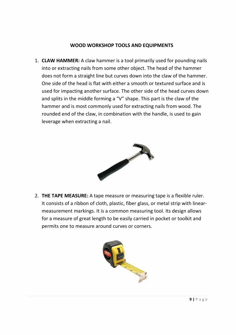
1. CLAW HAMMER: A claw hammer is a tool primarily used for pounding nails
into or extracting nails from some other object. The head of the hammer
does not form a straight line but curves down into the claw of the hammer.
One side of the head is flat with either a smooth or textured surface and is
used for impacting another surface. The other side of the head curves down
and splits in the middle forming a “V” shape. This part is the claw of the
hammer and is most commonly used for extracting nails from wood. The
rounded end of the claw, in combination with the handle, is used to gain
leverage when extracting a nail.
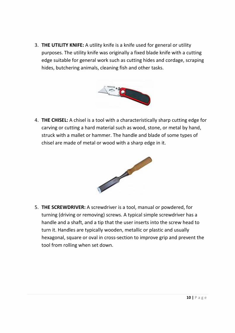
2. THE TAPE MEASURE: A tape measure or measuring tape is a flexible ruler.
It consists of a ribbon of cloth, plastic, fiber glass, or metal strip with linear-
measurement markings. It is a common measuring tool. Its design allows
for a measure of great length to be easily carried in pocket or toolkit and
permits one to measure around curves or corners.
10 | P a g e
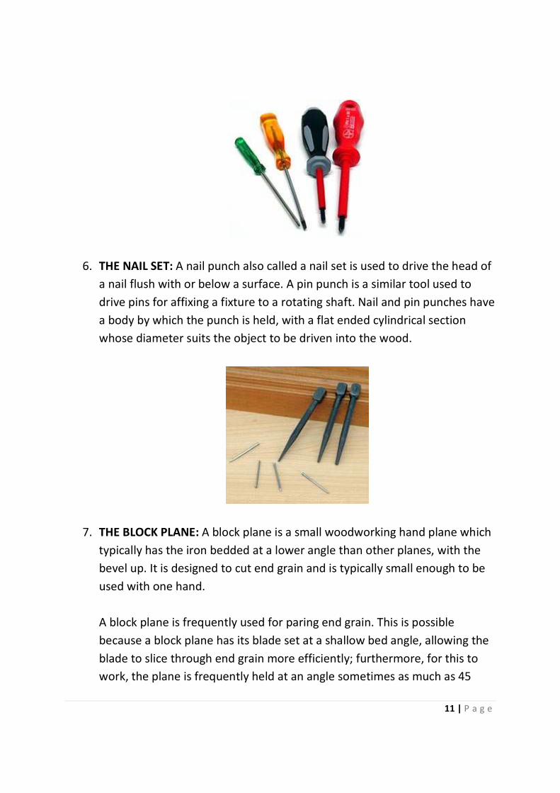
3. THE UTILITY KNIFE: A utility knife is a knife used for general or utility
purposes. The utility knife was originally a fixed blade knife with a cutting
edge suitable for general work such as cutting hides and cordage, scraping
hides, butchering animals, cleaning fish and other tasks.
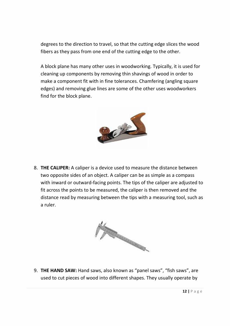
4. THE CHISEL: A chisel is a tool with a characteristically sharp cutting edge for
carving or cutting a hard material such as wood, stone, or metal by hand,
struck with a mallet or hammer. The handle and blade of some types of
chisel are made of metal or wood with a sharp edge in it.
5. THE SCREWDRIVER: A screwdriver is a tool, manual or powdered, for
turning (driving or removing) screws. A typical simple screwdriver has a
handle and a shaft, and a tip that the user inserts into the screw head to
turn it. Handles are typically wooden, metallic or plastic and usually
hexagonal, square or oval in cross-section to improve grip and prevent the
tool from rolling when set down.
11 | P a g e
6. THE NAIL SET: A nail punch also called a nail set is used to drive the head of
a nail flush with or below a surface. A pin punch is a similar tool used to
drive pins for affixing a fixture to a rotating shaft. Nail and pin punches have
a body by which the punch is held, with a flat ended cylindrical section
whose diameter suits the object to be driven into the wood.
7. THE BLOCK PLANE: A block plane is a small woodworking hand plane which
typically has the iron bedded at a lower angle than other planes, with the
bevel up. It is designed to cut end grain and is typically small enough to be
used with one hand.
A block plane is frequently used for paring end grain. This is possible
because a block plane has its blade set at a shallow bed angle, allowing the
blade to slice through end grain more efficiently; furthermore, for this to
work, the plane is frequently held at an angle sometimes as much as 45
12 | P a g e
degrees to the direction to travel, so that the cutting edge slices the wood
fibers as they pass from one end of the cutting edge to the other.
A block plane has many other uses in woodworking. Typically, it is used for
cleaning up components by removing thin shavings of wood in order to
make a component fit with in fine tolerances. Chamfering (angling square
edges) and removing glue lines are some of the other uses woodworkers
find for the block plane.
8. THE CALIPER: A caliper is a device used to measure the distance between
two opposite sides of an object. A caliper can be as simple as a compass
with inward or outward-facing points. The tips of the caliper are adjusted to
fit across the points to be measured, the caliper is then removed and the
distance read by measuring between the tips with a measuring tool, such as
a ruler.
9. THE HAND SAW: Hand saws, also known as “panel saws”, “fish saws”, are
used to cut pieces of wood into different shapes. They usually operate by

13 | P a g e
having a series of sharp points of some substance that is harder than the
wood being cut. The hand saw is a bit like a tenon saw, but with one flat,
sharp edge.
10. METAL DETECTOR: A metal detector is an electronic instrument which
detects the presence of metal nearby. Metal detectors are useful for
finding metal inclusions hidden within objects or metal objects buried
underground. They often consist of a handheld unit with a sensor probe
which can be swept over the ground or other objects. If the sensor comes
near a piece of metal this is indicated by a changing tone in earphones, or a
needle moving on an indicator. Usually the device gives some indication of
distance; the closer the metal is, the higher the tone in the earphone or the
higher the needle goes.
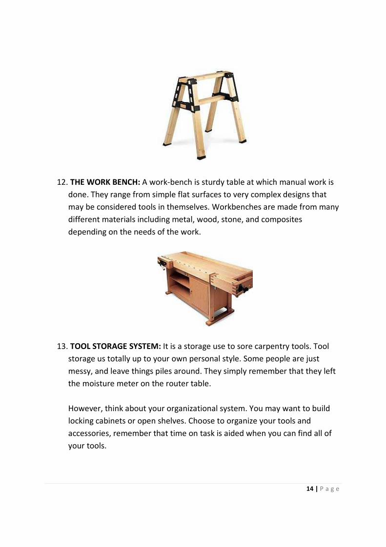
11. THE SAW HORSE: A saw-horse (saw-buck, trestle, buck) is a beam with four
legs used to support a board or plank for sawing. A pair of sawhorses can
support a plank, forming a scaffold. In certain circles, it is also known as a
mule and a short sawhorse is known as a pony.
14 | P a g e
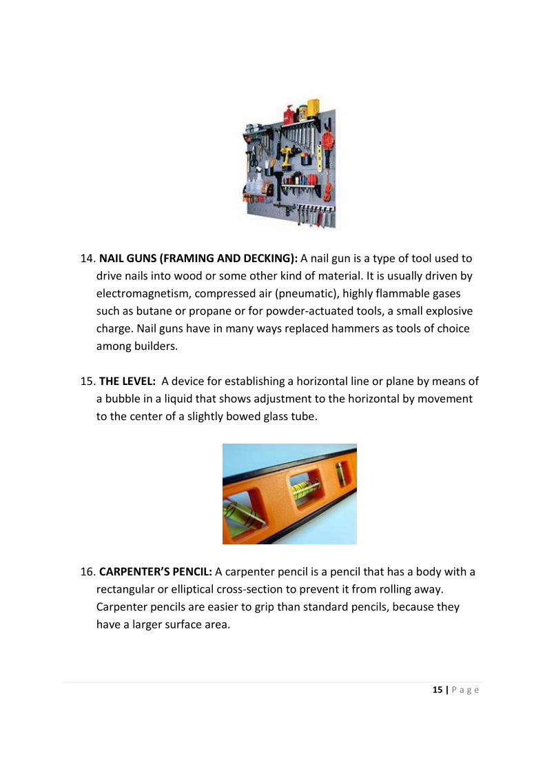
12. THE WORK BENCH: A work-bench is sturdy table at which manual work is
done. They range from simple flat surfaces to very complex designs that
may be considered tools in themselves. Workbenches are made from many
different materials including metal, wood, stone, and composites
depending on the needs of the work.
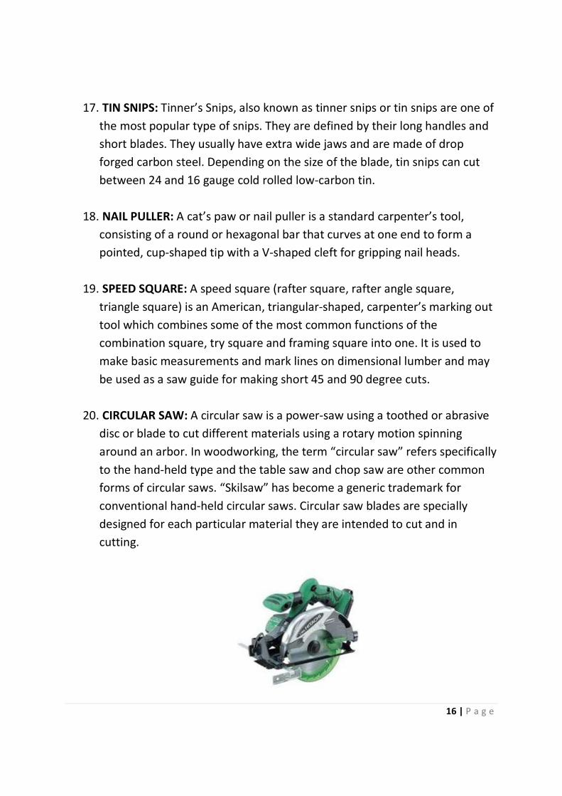
13. TOOL STORAGE SYSTEM: It is a storage use to sore carpentry tools. Tool
storage us totally up to your own personal style. Some people are just
messy, and leave things piles around. They simply remember that they left
the moisture meter on the router table.
However, think about your organizational system. You may want to build
locking cabinets or open shelves. Choose to organize your tools and
accessories, remember that time on task is aided when you can find all of
your tools.
15 | P a g e
14. NAIL GUNS (FRAMING AND DECKING): A nail gun is a type of tool used to
drive nails into wood or some other kind of material. It is usually driven by
electromagnetism, compressed air (pneumatic), highly flammable gases
such as butane or propane or for powder-actuated tools, a small explosive
charge. Nail guns have in many ways replaced hammers as tools of choice
among builders.
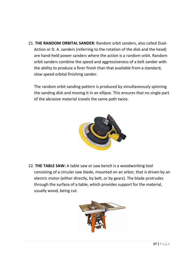
15. THE LEVEL: A device for establishing a horizontal line or plane by means of
a bubble in a liquid that shows adjustment to the horizontal by movement
to the center of a slightly bowed glass tube.
16. CARPENTER’S PENCIL: A carpenter pencil is a pencil that has a body with a
rectangular or elliptical cross-section to prevent it from rolling away.
Carpenter pencils are easier to grip than standard pencils, because they
have a larger surface area.
16 | P a g e
17. TIN SNIPS: Tinner’s Snips, also known as tinner snips or tin snips are one of
the most popular type of snips. They are defined by their long handles and
short blades. They usually have extra wide jaws and are made of drop
forged carbon steel. Depending on the size of the blade, tin snips can cut
between 24 and 16 gauge cold rolled low-carbon tin.
18. NAIL PULLER: A cat’s paw or nail puller is a standard carpenter’s tool,
consisting of a round or hexagonal bar that curves at one end to form a
pointed, cup-shaped tip with a V-shaped cleft for gripping nail heads.
19. SPEED SQUARE: A speed square (rafter square, rafter angle square,
triangle square) is an American, triangular-shaped, carpenter’s marking out
tool which combines some of the most common functions of the
combination square, try square and framing square into one. It is used to
make basic measurements and mark lines on dimensional lumber and may
be used as a saw guide for making short 45 and 90 degree cuts.
20. CIRCULAR SAW: A circular saw is a power-saw using a toothed or abrasive
disc or blade to cut different materials using a rotary motion spinning
around an arbor. In woodworking, the term “circular saw” refers specifically
to the hand-held type and the table saw and chop saw are other common
forms of circular saws. “Skilsaw” has become a generic trademark for
conventional hand-held circular saws. Circular saw blades are specially
designed for each particular material they are intended to cut and in
cutting.
17 | P a g e
21. THE RANDOM ORBITAL SANDER: Random orbit sanders, also called Dual-
Action or D. A. sanders (referring to the rotation of the disk and the head)
are hand-held power sanders where the action is a random orbit. Random
orbit sanders combine the speed and aggressiveness of a belt sander with
the ability to produce a finer finish than that available from a standard,
slow speed orbital finishing sander.
The random orbit sanding pattern is produced by simultaneously spinning
the sanding disk and moving it in an ellipse. This ensures that no single part
of the abrasive material travels the same path twice.
22. THE TABLE SAW: A table saw or saw bench is a woodworking tool
consisting of a circular saw blade, mounted on an arbor, that is driven by an
electric motor (either directly, by belt, or by gears). The blade protrudes
through the surface of a table, which provides support for the material,
usually wood, being cut.
18 | P a g e
23. BRADAWL: A bradawl is used to make an indentation in wood or other
materials in order to ease the insertion of a nail or screw.
24. RUBBER/PLASTIC HAMMER: A combination tool with rubber and plastic
heads designed to protect the surface being struck. It is usually used on
finished surfaces.
25. WOOD WORKER’S VICE: An adjustable device used to hold wood for
forming or cutting.
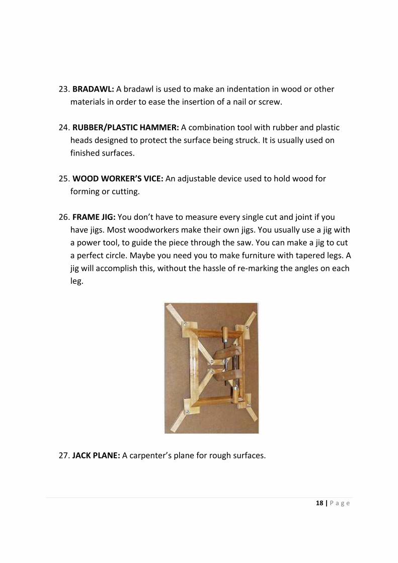
26. FRAME JIG: You don’t have to measure every single cut and joint if you
have jigs. Most woodworkers make their own jigs. You usually use a jig with
a power tool, to guide the piece through the saw. You can make a jig to cut
a perfect circle. Maybe you need you to make furniture with tapered legs. A
jig will accomplish this, without the hassle of re-marking the angles on each
leg.
27. JACK PLANE: A carpenter’s plane for rough surfaces.
19 | P a g e
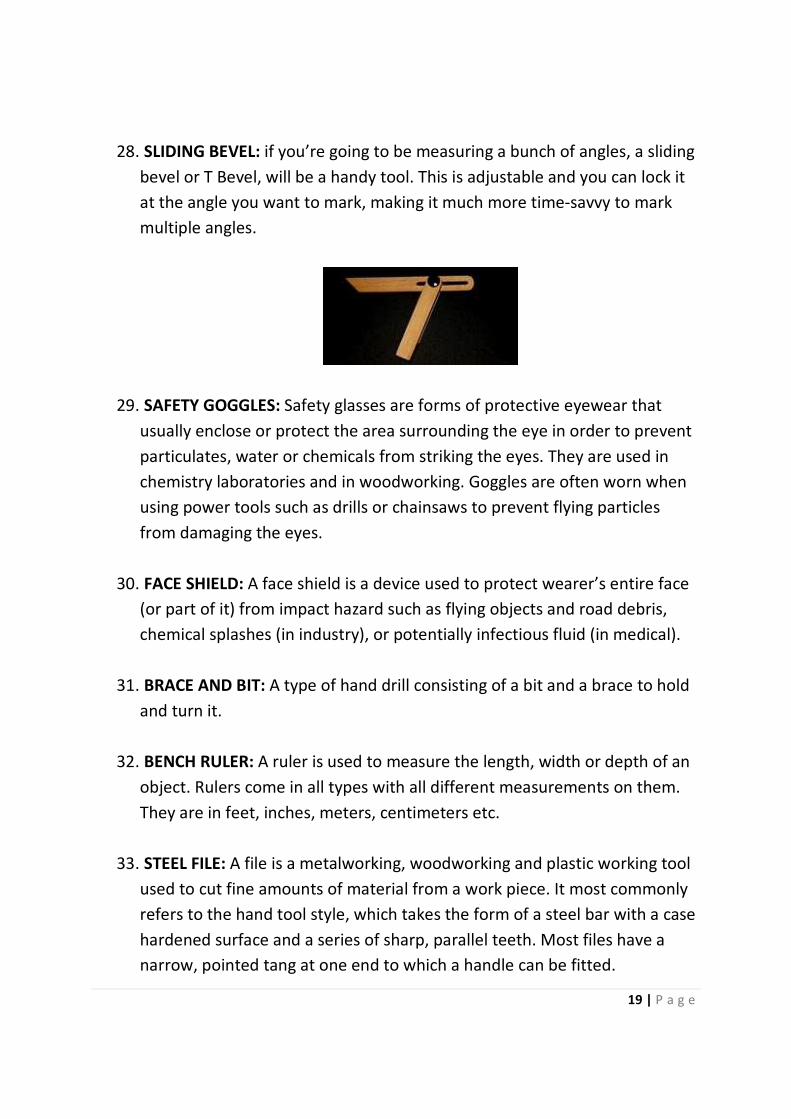
28. SLIDING BEVEL: if you’re going to be measuring a bunch of angles, a sliding
bevel or T Bevel, will be a handy tool. This is adjustable and you can lock it
at the angle you want to mark, making it much more time-savvy to mark
multiple angles.
29. SAFETY GOGGLES: Safety glasses are forms of protective eyewear that
usually enclose or protect the area surrounding the eye in order to prevent
particulates, water or chemicals from striking the eyes. They are used in
chemistry laboratories and in woodworking. Goggles are often worn when
using power tools such as drills or chainsaws to prevent flying particles
from damaging the eyes.
30. FACE SHIELD: A face shield is a device used to protect wearer’s entire face
(or part of it) from impact hazard such as flying objects and road debris,
chemical splashes (in industry), or potentially infectious fluid (in medical).
31. BRACE AND BIT: A type of hand drill consisting of a bit and a brace to hold
and turn it.
32. BENCH RULER: A ruler is used to measure the length, width or depth of an
object. Rulers come in all types with all different measurements on them.
They are in feet, inches, meters, centimeters etc.
33. STEEL FILE: A file is a metalworking, woodworking and plastic working tool
used to cut fine amounts of material from a work piece. It most commonly
refers to the hand tool style, which takes the form of a steel bar with a case
hardened surface and a series of sharp, parallel teeth. Most files have a
narrow, pointed tang at one end to which a handle can be fitted.
20 | P a g e
34. DRILL: A drill is a tool fitted with a cutting tool attachment or driving tool
attachment, usually a drill bit or driver bit, used for boring holes in various
materials or fastening various materials together with the use of fasteners.
The attachment is gripped by a chuck at one end of the drill and rotated
while pressed against the target material. The tip, and sometimes edges, of
the cutting tool does the work of cutting into the target material. This may
be slicing off thin shavings (twist drills or auger bits), grinding off small
particles (oil drilling), crushing and removing pieces of the work piece (SDS
masonry drill), countersinking, counter-boring or other operations.
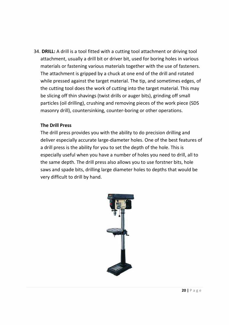
The Drill Press
The drill press provides you with the ability to do precision drilling and
deliver especially accurate large-diameter holes. One of the best features of
a drill press is the ability for you to set the depth of the hole. This is
especially useful when you have a number of holes you need to drill, all to
the same depth. The drill press also allows you to use forstner bits, hole
saws and spade bits, drilling large diameter holes to depths that would be
very difficult to drill by hand.
21 | P a g e
35. PLYWOOD SAW: A plywood saw is a saw that has a fine-toothed blade that
minimizes tearing of the outer plies of a sheet of plywood. An extra set of
teeth on the curved upper edge of the blade allows starting of a cut on the
inside of a panel (away from the edge) without having to drill a starting
hole. The standard plywood saw blade is 11 inches long and has 14 tpi
(teeth per inch).
36. RECIPROCATING SAW: A reciprocating saw is a type of saw in which the
cutting actions is achieved through a push and pull reciprocating motion of
the blade.
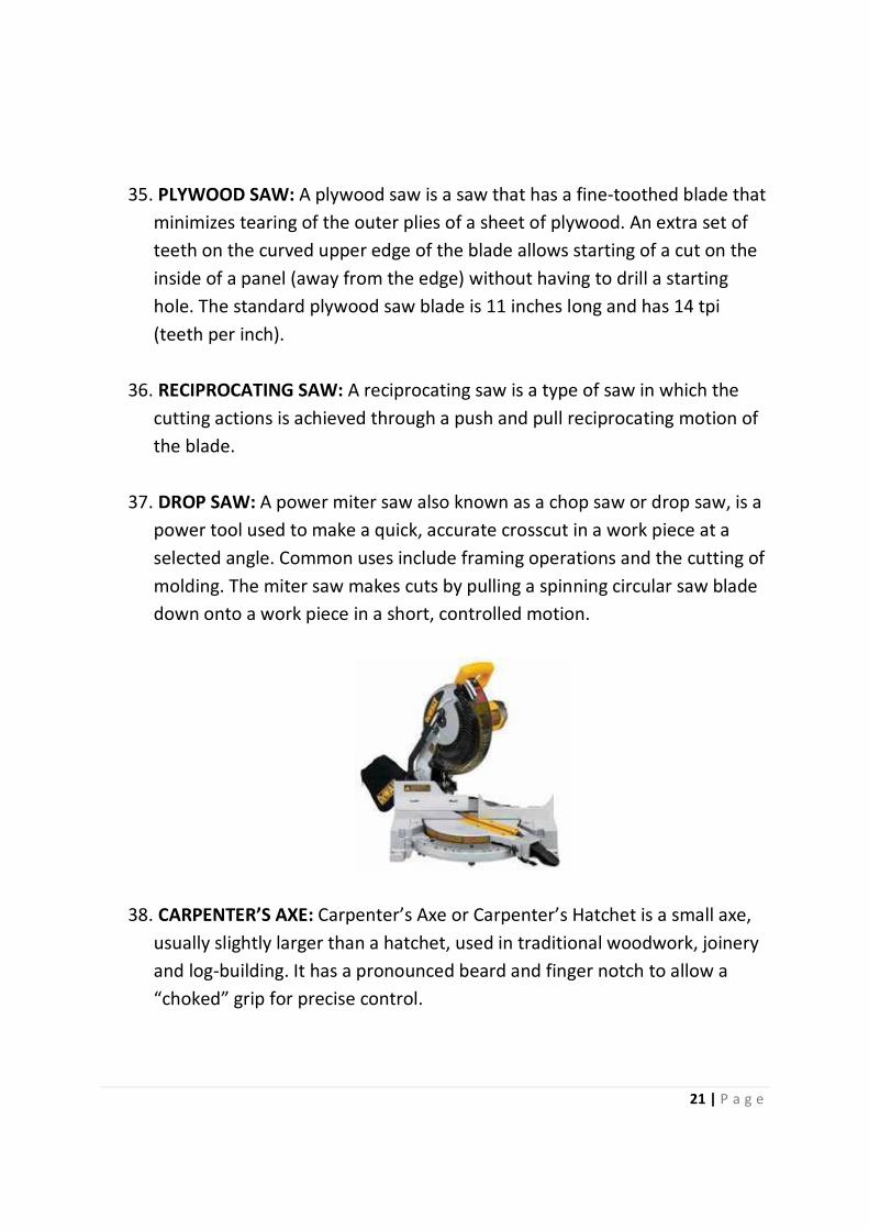
37. DROP SAW: A power miter saw also known as a chop saw or drop saw, is a
power tool used to make a quick, accurate crosscut in a work piece at a
selected angle. Common uses include framing operations and the cutting of
molding. The miter saw makes cuts by pulling a spinning circular saw blade
down onto a work piece in a short, controlled motion.
38. CARPENTER’S AXE: Carpenter’s Axe or Carpenter’s Hatchet is a small axe,
usually slightly larger than a hatchet, used in traditional woodwork, joinery
and log-building. It has a pronounced beard and finger notch to allow a
“choked” grip for precise control.

22 | P a g e
39. FRAMING SQUARE: These dedicated right angles keep projects square,
especially during assembly. A large square measuring 24 by 16 inches get
the most use in cabinetry, for which perfectly square boxes are critical.
Framing squares also come in handy for checking square edges on large
work pieces such as plywood and doors. Smaller dedicated squares also
come in handy for tighter spaces where standard 24-inch squares cannot
fit.
40. TRY SQUARE: Similar to larger framing squares, try squares are dedicated
right angles. However, unlike framing squares, try squares have a metal
blade fastened into a wooden handle rather than single-body construction.
The thicker wooden handle provides a lip on either edge of the blade,
allowing the tool to rest on the work piece more easily than its larger
single-bodied counterpart.
41. COMBINATION SQUARE: A favourite of many wood workers, the
combination square is one of the most versatile tools in the shop. In its
simplest form, the combo verifies square edges and flat surfaces of work
pieces. Beyond that purpose, the adjustable head of the combo is crucial
for calibrating or checking machinery and laying out joinery. Because of this
tool’s practicality, most shops have several combination squares on hand in
sizes ranging from 4 to 12 inches.
42. BENCH VICE: Vice is a mechanical apparatus used to secure an object to
allow work to be performed on it. Vices have two parallel jaws, one fixed
and the other movable, threaded in and out by a screw lever.
43. HAND SCRAPPER: A hand scrapper is a single-edged tool used to scrape
metal from a surface. This may be required where a surface needs to be
trued, corrected for fit to a mating part, needs to retain oil (usually on a
freshly ground surface), or even to give a decorative finish. Surface plates
were traditionally made by scraping.

23 | P a g e
44. JIGSAW (POWER TOOL): A jigsaw power tool is a jigsaw made up of a
reciprocating saw blade. A jigsaw with a bevel function on the sole plate
allows cutting angles of typically up to 45 degrees relative to the normal
vertical stroke for cutting miter joints. In the past, what are now usually
called scroll saws were often referred to as jig saws.

24 | P a g e
WOOD JOINERY
What is wood joinery?
Wood joinery is a part of woodworking that involves joining together pieces of
wood, to produce more complex items. Some wood joints employ fasteners,
bindings or adhesives, while others use only wood elements.
TYPES OF WOOD JOINTS
1. BUTT JOINT: A butt joint is nothing more than when one piece of wood
butts into another (most often at a right angle, or square to the other
board) and is fastened using mechanical fasteners. This type of joint is often
used in wall framing on construction sites. To create a butt joint, simply
place the end of a piece of wood against another piece and fasten either
using a metal clip, a nail or a screw. Butt joints may not be the fanciest or
nicest looking joints, but they are extremely stable and can hold up fairly
heavy loads.
2. MITERED BUTT JOINT: The mitered butt joint is very similar to the standard
butt joint, in that it typically joints two boards at their ends, or one board at
an end meeting the side of another board. The difference is in how those
ends meet. In a standard butt joint, the end or ends are left square so they
meet at a 90 degree angle. In a mitered butt joint, the end or ends are
mitered to a 45 degree angle. This allows two boards to turn a corner
25 | P a g e
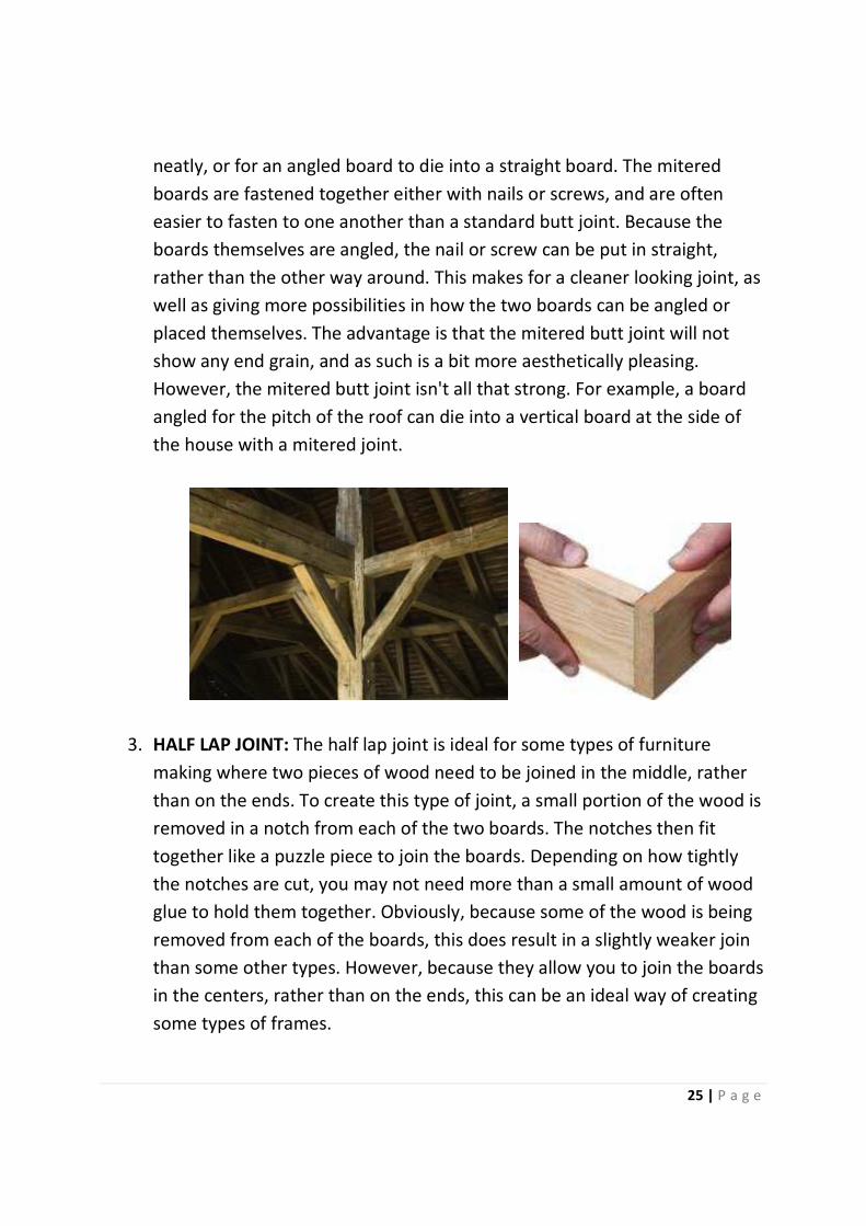
neatly, or for an angled board to die into a straight board. The mitered
boards are fastened together either with nails or screws, and are often
easier to fasten to one another than a standard butt joint. Because the
boards themselves are angled, the nail or screw can be put in straight,
rather than the other way around. This makes for a cleaner looking joint, as
well as giving more possibilities in how the two boards can be angled or
placed themselves. The advantage is that the mitered butt joint will not
show any end grain, and as such is a bit more aesthetically pleasing.
However, the mitered butt joint isn't all that strong. For example, a board
angled for the pitch of the roof can die into a vertical board at the side of
the house with a mitered joint.
3. HALF LAP JOINT: The half lap joint is ideal for some types of furniture
making where two pieces of wood need to be joined in the middle, rather
than on the ends. To create this type of joint, a small portion of the wood is
removed in a notch from each of the two boards. The notches then fit
together like a puzzle piece to join the boards. Depending on how tightly
the notches are cut, you may not need more than a small amount of wood
glue to hold them together. Obviously, because some of the wood is being
removed from each of the boards, this does result in a slightly weaker join
than some other types. However, because they allow you to join the boards
in the centers, rather than on the ends, this can be an ideal way of creating
some types of frames.
26 | P a g e
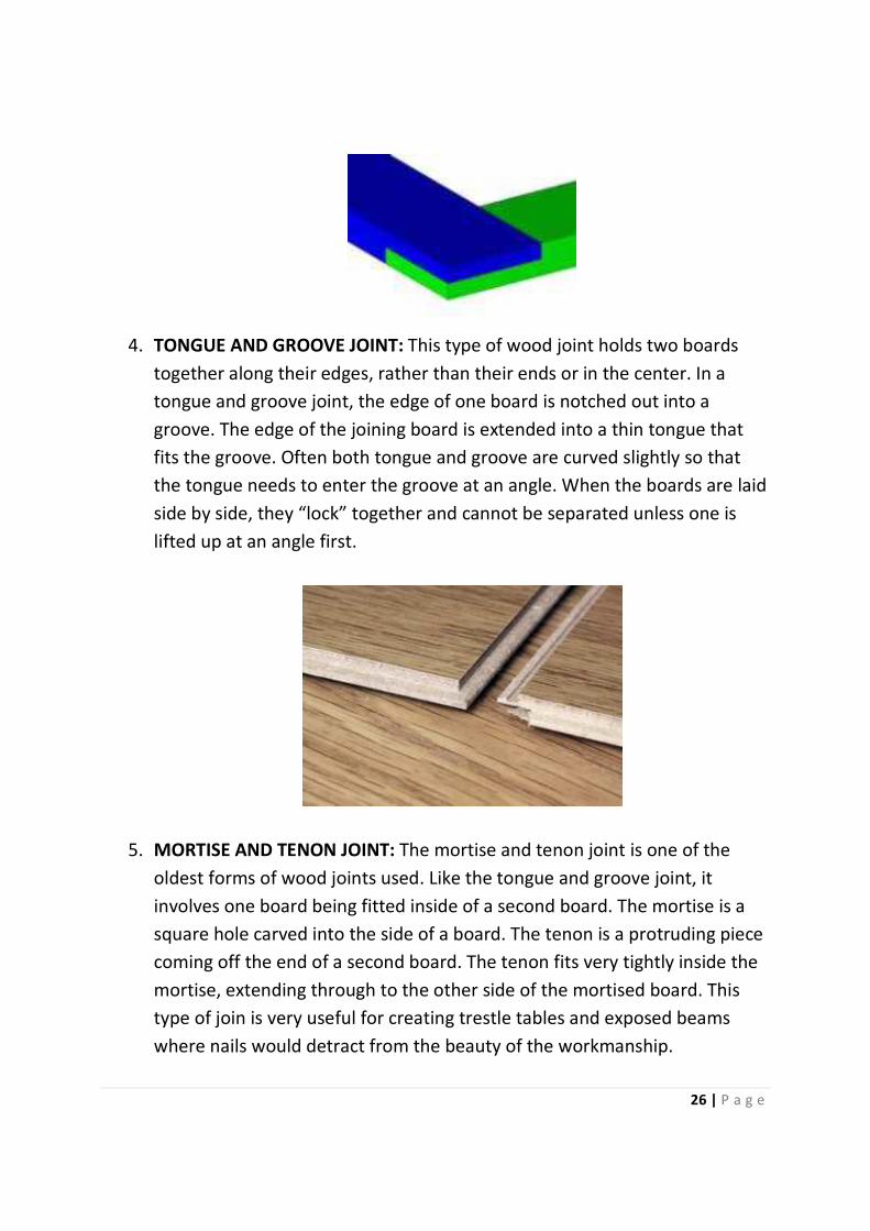
4. TONGUE AND GROOVE JOINT: This type of wood joint holds two boards
together along their edges, rather than their ends or in the center. In a
tongue and groove joint, the edge of one board is notched out into a
groove. The edge of the joining board is extended into a thin tongue that
fits the groove. Often both tongue and groove are curved slightly so that
the tongue needs to enter the groove at an angle. When the boards are laid
side by side, they “lock” together and cannot be separated unless one is
lifted up at an angle first.
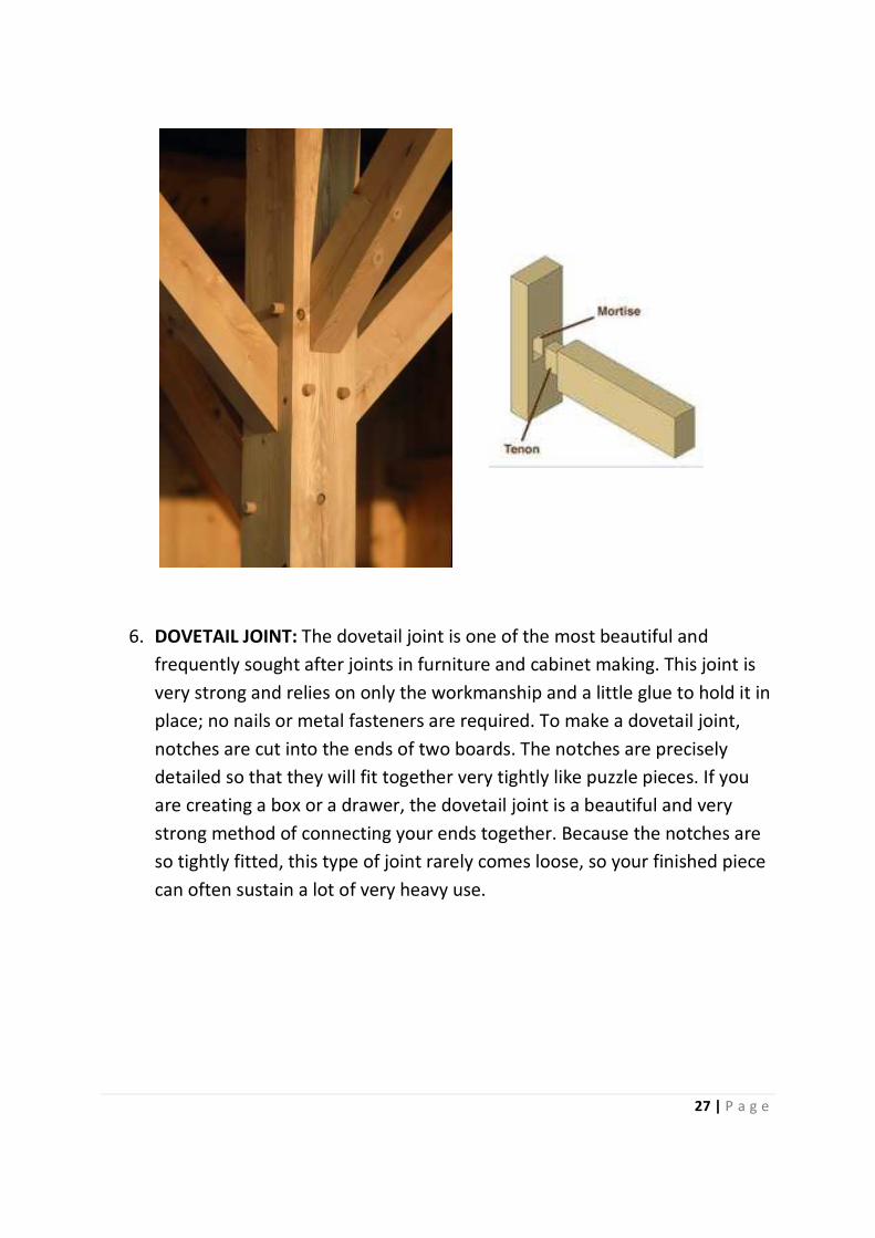
5. MORTISE AND TENON JOINT: The mortise and tenon joint is one of the
oldest forms of wood joints used. Like the tongue and groove joint, it
involves one board being fitted inside of a second board. The mortise is a
square hole carved into the side of a board. The tenon is a protruding piece
coming off the end of a second board. The tenon fits very tightly inside the
mortise, extending through to the other side of the mortised board. This
type of join is very useful for creating trestle tables and exposed beams
where nails would detract from the beauty of the workmanship.
27 | P a g e
6. DOVETAIL JOINT: The dovetail joint is one of the most beautiful and
frequently sought after joints in furniture and cabinet making. This joint is
very strong and relies on only the workmanship and a little glue to hold it in
place; no nails or metal fasteners are required. To make a dovetail joint,
notches are cut into the ends of two boards. The notches are precisely
detailed so that they will fit together very tightly like puzzle pieces. If you
are creating a box or a drawer, the dovetail joint is a beautiful and very
strong method of connecting your ends together. Because the notches are
so tightly fitted, this type of joint rarely comes loose, so your finished piece
can often sustain a lot of very heavy use.
28 | P a g e
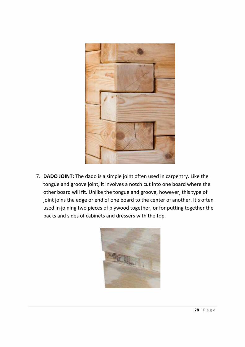
7. DADO JOINT: The dado is a simple joint often used in carpentry. Like the
tongue and groove joint, it involves a notch cut into one board where the
other board will fit. Unlike the tongue and groove, however, this type of
joint joins the edge or end of one board to the center of another. It’s often
used in joining two pieces of plywood together, or for putting together the
backs and sides of cabinets and dressers with the top.

29 | P a g e
8. RABBET JOINT: A rabbet is essentially a dado cut along the edge of a board.
It is used for joining cabinets or for making boxes where two edges need to
fit together tightly. Rabbets are often used at the back of cabinets and
other similar assemblies for attaching the back to the sides of the box,
adding a considerable amount of strength to the assembly.
30 | P a g e
WOODWORKING PROCESSES AND OPERATIONS
1. ASSEMBLY
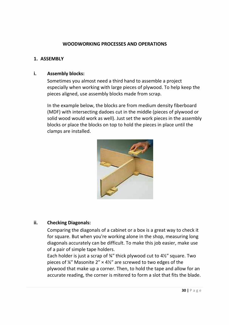
i. Assembly blocks:
Sometimes you almost need a third hand to assemble a project
especially when working with large pieces of plywood. To help keep the
pieces aligned, use assembly blocks made from scrap.
In the example below, the blocks are from medium density fiberboard
(MDF) with intersecting dadoes cut in the middle (pieces of plywood or
solid wood would work as well). Just set the work pieces in the assembly
blocks or place the blocks on top to hold the pieces in place until the
clamps are installed.
ii. Checking Diagonals:
Comparing the diagonals of a cabinet or a box is a great way to check it
for square. But when you're working alone in the shop, measuring long
diagonals accurately can be difficult. To make this job easier, make use
of a pair of simple tape holders.
Each holder is just a scrap of ¾″ thick plywood cut to 4½″ square. Two
pieces of ¼″ Masonite 2″ × 4½″ are screwed to two edges of the
plywood that make up a corner. Then, to hold the tape and allow for an
accurate reading, the corner is mitered to form a slot that fits the blade.

31 | P a g e
iii. Drilling pocket Holes in thick stock:
Pocket hole joinery can be a quick, efficient way to pull your
woodworking project together, especially if you don't have the time or
need to cut tenons, dadoes, and rabbits. A simple pocket hole jig, as
shown in the drawings below, makes the work even easier by guiding
your drill bit exactly 15° — ideal for securing two pieces of stock at a
right angle.
In example below which is a Workbench Rustic Retreat Deck Project,
there is need of a quick way to secure 2×4 hand rails to the posts. Pocket
hole joinery was the perfect solution. Use a pocket hole jig to make sure
all the deck screw holes were positioned exactly where we wanted
them.
Setting up the jig is easy. Position it on the top surface of the rail where
the screws are to enter and use a face clamp to hold it in place while
drilling (as shown in the diagram below). Pull the jig snug against the
end or your stock and the jig stop will position your holes in the same
place on every board. If you're working with 2×4 rails, use the extension

32 | P a g e
stop (included with the jig) to make sure the screw will exit at the center
of the board (Fig. 2a). The jig includes two drill holes, which provide
some different hole spacing options when you align the jig against the
left and right edges of your board (Fig. 1a).
Note in Figure 2a, that a special bit (included with the jig) was used to
create a deep counter-bored pocket and shank hole for the screw. Note
that the shank hole doesn't go through the end of the board, but enters
just far enough to get the deck screw started in the right direction. We
also used a spacer block to support the rail while driving the screws into
the post (Fig. 2).
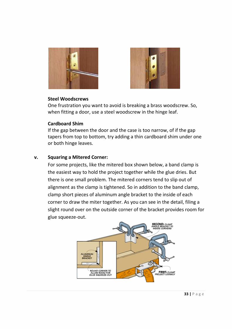
iv. Installing Hinges:
When installing hinges, you need to be ready to make a few
adjustments. This can mean putting on and taking off the door a few
times. And one thing to avoid is breaking one of the brass woodscrews.
So, use a single steel woodscrew to hold each leaf during the fitting
process, see top photo below.
And if the hinge mortise is too deep, use a thin piece of cardboard as a
shim, see bottom photo below.
33 | P a g e
Steel Woodscrews
One frustration you want to avoid is breaking a brass woodscrew. So,
when fitting a door, use a steel woodscrew in the hinge leaf.
Cardboard Shim
If the gap between the door and the case is too narrow, of if the gap
tapers from top to bottom, try adding a thin cardboard shim under one
or both hinge leaves.
v. Squaring a Mitered Corner:
For some projects, like the mitered box shown below, a band clamp is
the easiest way to hold the project together while the glue dries. But
there is one small problem. The mitered corners tend to slip out of
alignment as the clamp is tightened. So in addition to the band clamp,
clamp short pieces of aluminum angle bracket to the inside of each
corner to draw the miter together. As you can see in the detail, filing a
slight round over on the outside corner of the bracket provides room for
glue squeeze-out.
34 | P a g e
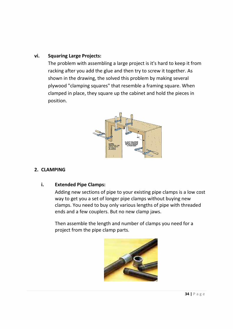
vi. Squaring Large Projects:
The problem with assembling a large project is it's hard to keep it from
racking after you add the glue and then try to screw it together. As
shown in the drawing, the solved this problem by making several
plywood "clamping squares" that resemble a framing square. When
clamped in place, they square up the cabinet and hold the pieces in
position.
2. CLAMPING
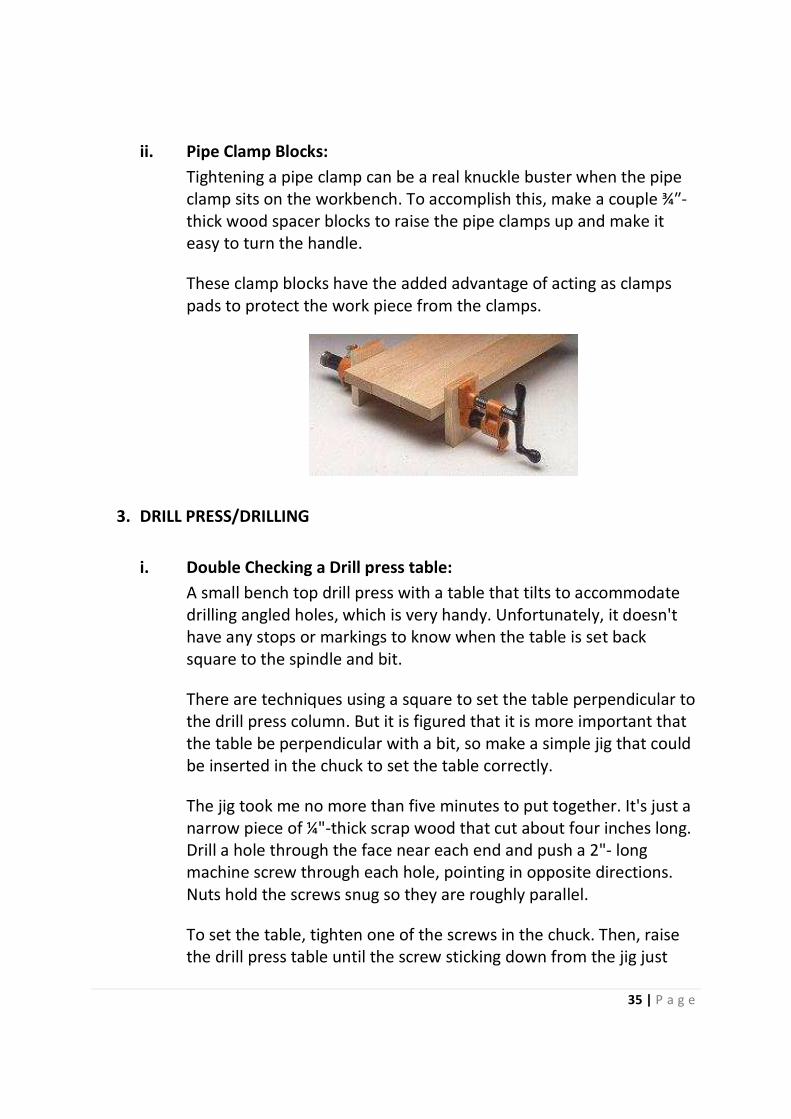
i. Extended Pipe Clamps:
Adding new sections of pipe to your existing pipe clamps is a low cost
way to get you a set of longer pipe clamps without buying new
clamps. You need to buy only various lengths of pipe with threaded
ends and a few couplers. But no new clamp jaws.
Then assemble the length and number of clamps you need for a
project from the pipe clamp parts.
35 | P a g e
ii. Pipe Clamp Blocks:
Tightening a pipe clamp can be a real knuckle buster when the pipe
clamp sits on the workbench. To accomplish this, make a couple ¾″-
thick wood spacer blocks to raise the pipe clamps up and make it
easy to turn the handle.
These clamp blocks have the added advantage of acting as clamps
pads to protect the work piece from the clamps.
3. DRILL PRESS/DRILLING
i. Double Checking a Drill press table:
A small bench top drill press with a table that tilts to accommodate
drilling angled holes, which is very handy. Unfortunately, it doesn't
have any stops or markings to know when the table is set back
square to the spindle and bit.
There are techniques using a square to set the table perpendicular to
the drill press column. But it is figured that it is more important that
the table be perpendicular with a bit, so make a simple jig that could
be inserted in the chuck to set the table correctly.
The jig took me no more than five minutes to put together. It's just a
narrow piece of ¼"-thick scrap wood that cut about four inches long.
Drill a hole through the face near each end and push a 2"- long
machine screw through each hole, pointing in opposite directions.
Nuts hold the screws snug so they are roughly parallel.
To set the table, tighten one of the screws in the chuck. Then, raise
the drill press table until the screw sticking down from the jig just
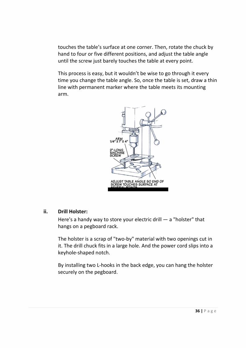
36 | P a g e
touches the table’s surface at one corner. Then, rotate the chuck by
hand to four or five different positions, and adjust the table angle
until the screw just barely touches the table at every point.
This process is easy, but it wouldn’t be wise to go through it every
time you change the table angle. So, once the table is set, draw a thin
line with permanent marker where the table meets its mounting
arm.
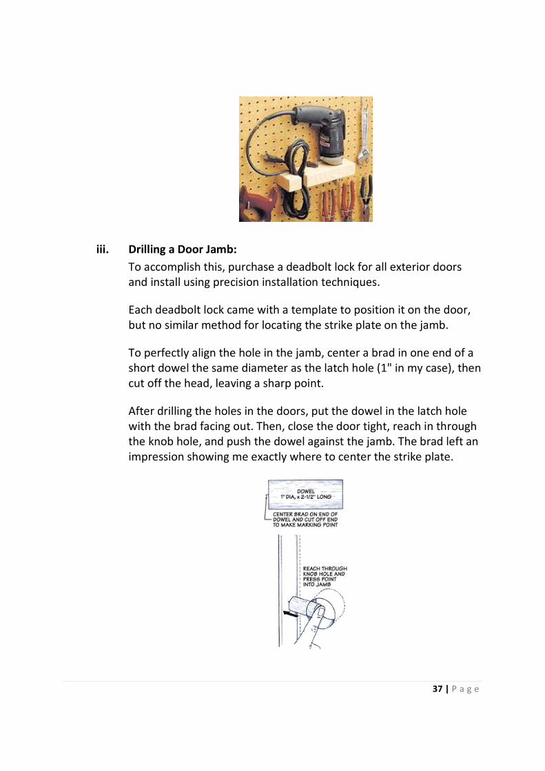
ii. Drill Holster:
Here's a handy way to store your electric drill — a "holster" that
hangs on a pegboard rack.
The holster is a scrap of "two-by" material with two openings cut in
it. The drill chuck fits in a large hole. And the power cord slips into a
keyhole-shaped notch.
By installing two L-hooks in the back edge, you can hang the holster
securely on the pegboard.
37 | P a g e
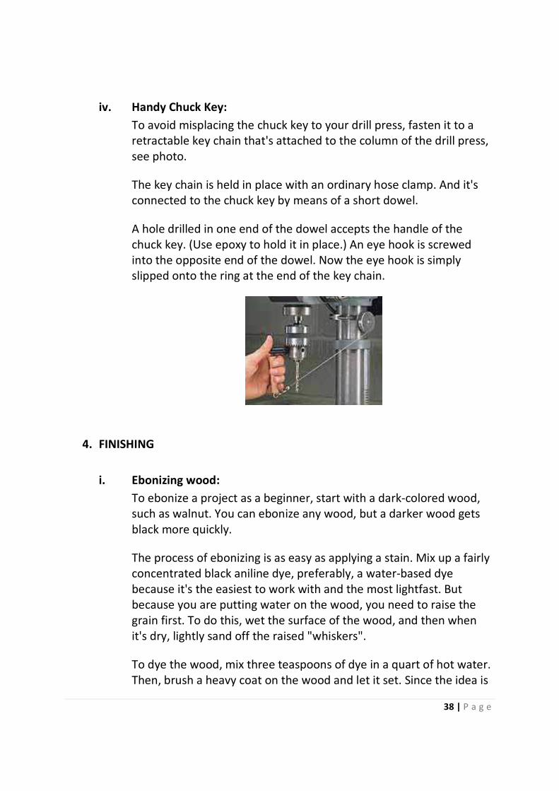
iii. Drilling a Door Jamb:
To accomplish this, purchase a deadbolt lock for all exterior doors
and install using precision installation techniques.
Each deadbolt lock came with a template to position it on the door,
but no similar method for locating the strike plate on the jamb.
To perfectly align the hole in the jamb, center a brad in one end of a
short dowel the same diameter as the latch hole (1" in my case), then
cut off the head, leaving a sharp point.
After drilling the holes in the doors, put the dowel in the latch hole
with the brad facing out. Then, close the door tight, reach in through
the knob hole, and push the dowel against the jamb. The brad left an
impression showing me exactly where to center the strike plate.
38 | P a g e
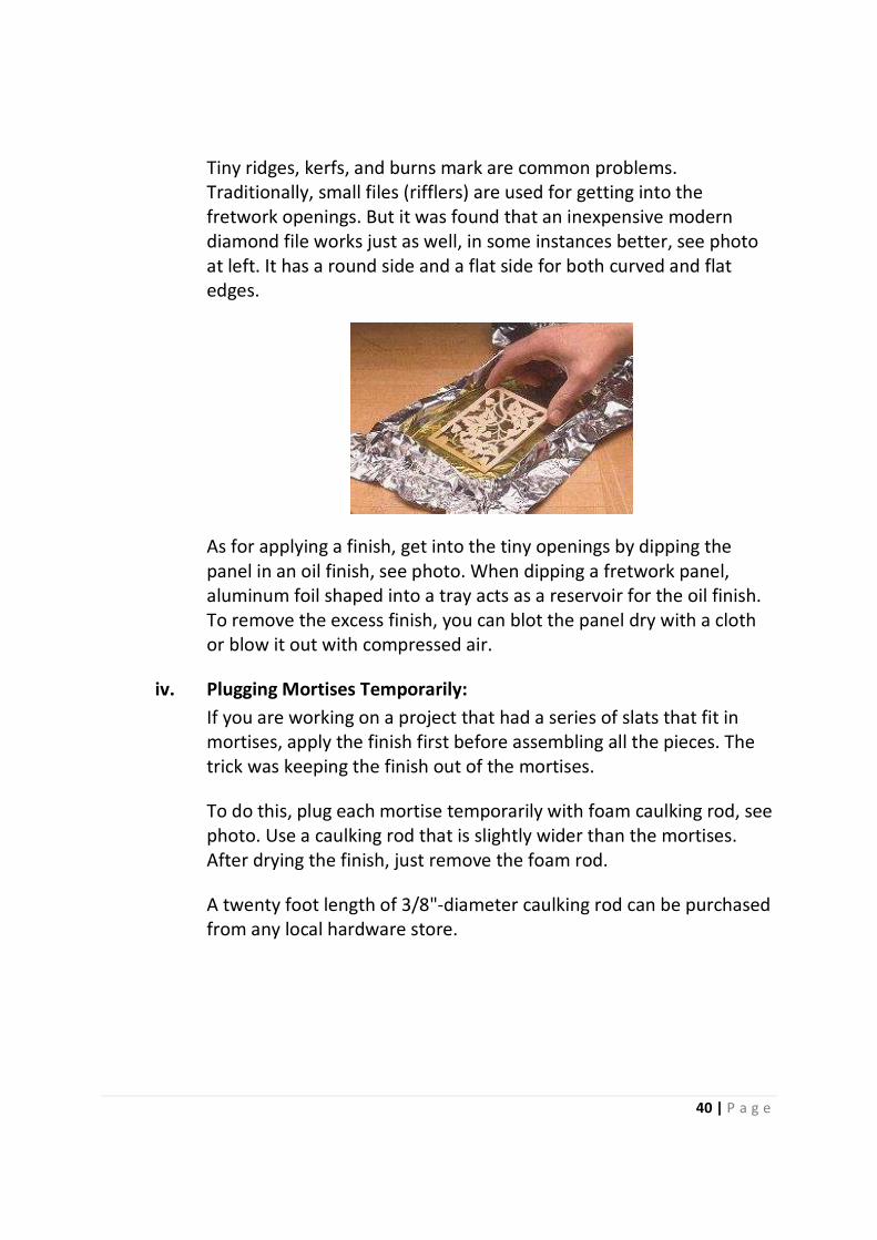
iv. Handy Chuck Key:
To avoid misplacing the chuck key to your drill press, fasten it to a
retractable key chain that's attached to the column of the drill press,
see photo.
The key chain is held in place with an ordinary hose clamp. And it's
connected to the chuck key by means of a short dowel.
A hole drilled in one end of the dowel accepts the handle of the
chuck key. (Use epoxy to hold it in place.) An eye hook is screwed
into the opposite end of the dowel. Now the eye hook is simply
slipped onto the ring at the end of the key chain.
4. FINISHING
i. Ebonizing wood:
To ebonize a project as a beginner, start with a dark-colored wood,
such as walnut. You can ebonize any wood, but a darker wood gets
black more quickly.
The process of ebonizing is as easy as applying a stain. Mix up a fairly
concentrated black aniline dye, preferably, a water-based dye
because it's the easiest to work with and the most lightfast. But
because you are putting water on the wood, you need to raise the
grain first. To do this, wet the surface of the wood, and then when
it's dry, lightly sand off the raised "whiskers".
To dye the wood, mix three teaspoons of dye in a quart of hot water.
Then, brush a heavy coat on the wood and let it set. Since the idea is

39 | P a g e
to get the wood as dark as possible, don't bother to wipe off the
excess. In fact, you may want to apply a couple more coats. When it's
dry, simply apply a finish.
ii. Finishing Dowels:
To provide better coverage when applying stain to a dowel, cut a V-
shaped notch in a foam brush.
iii. Finishing Fretwork:
Here are a couple of tricks you can use to put the finishing touches
on fretwork panels.
40 | P a g e
Tiny ridges, kerfs, and burns mark are common problems.
Traditionally, small files (rifflers) are used for getting into the
fretwork openings. But it was found that an inexpensive modern
diamond file works just as well, in some instances better, see photo
at left. It has a round side and a flat side for both curved and flat
edges.
As for applying a finish, get into the tiny openings by dipping the
panel in an oil finish, see photo. When dipping a fretwork panel,
aluminum foil shaped into a tray acts as a reservoir for the oil finish.
To remove the excess finish, you can blot the panel dry with a cloth
or blow it out with compressed air.
iv. Plugging Mortises Temporarily:
If you are working on a project that had a series of slats that fit in
mortises, apply the finish first before assembling all the pieces. The
trick was keeping the finish out of the mortises.
To do this, plug each mortise temporarily with foam caulking rod, see
photo. Use a caulking rod that is slightly wider than the mortises.
After drying the finish, just remove the foam rod.
A twenty foot length of 3/8"-diameter caulking rod can be purchased
from any local hardware store.

41 | P a g e
v. Shop-Made Foam Brushes:
Use foam brushes to touch up small areas. To make "instant" foam
brushes, stick pieces of self-adhesive foam weather stripping on
sticks made from scrap pieces of wood. For larger brushes, wrap the
weather stripping around the end of the wooden stick.
vi. Staining End Grain:
When applying liquid stains, the stain soaks more deeply into the
pores of the end grain than the face grain, darkening the ends much
more than the faces, see top photo.
One way to even out the stain color is to sand the end grain with a
higher-grit sandpaper than the face grain.
In the bottom photo, the face is sanded with 220-grit and the end
grain with 600-grit, resulting is a much better color match.
42 | P a g e
5. GLUING
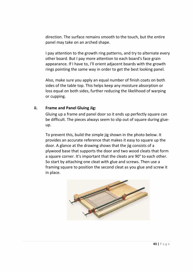
i. Avoid Warp in a glued-up panel:
I'm getting ready to build a table. A woodworker friend told me when
I glue up the top, I should alternate the orientation of the boards.
Another told me it doesn't matter which way I place the boards.
Who's right?
Actually, neither of your friends is wrong. They're talking about
orienting the boards so the growth rings visible in the end grain arc
up on one board and down on the next, or all arc consistently in the
same direction.
If you alternate the boards, your panel should remain flat across its
overall width, as each board cups in the opposite direction. But the
panel surface may feel wavy.
On the other hand, if you glue-up the boards with the growth rings all
oriented in the same direction, the whole panel may cup in one
43 | P a g e
direction. The surface remains smooth to the touch, but the entire
panel may take on an arched shape.
I pay attention to the growth ring patterns, and try to alternate every
other board. But I pay more attention to each board's face grain
appearance. If I have to, I'll orient adjacent boards with the growth
rings pointing the same way in order to get the best looking panel.
Also, make sure you apply an equal number of finish coats on both
sides of the table top. This helps keep any moisture absorption or
loss equal on both sides, further reducing the likelihood of warping
or cupping.
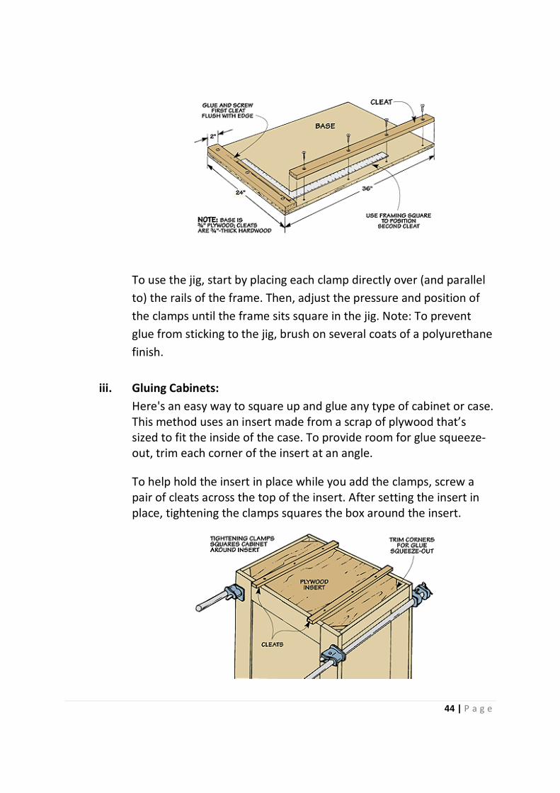
ii. Frame and Panel Gluing Jig:
Gluing up a frame and panel door so it ends up perfectly square can
be difficult. The pieces always seem to slip out of square during glue-
up.
To prevent this, build the simple jig shown in the photo below. It
provides an accurate reference that makes it easy to square up the
door. A glance at the drawing shows that the jig consists of a
plywood base that supports the door and two wood cleats that form
a square corner. It's important that the cleats are 90° to each other.
So start by attaching one cleat with glue and screws. Then use a
framing square to position the second cleat as you glue and screw it
in place.
44 | P a g e
To use the jig, start by placing each clamp directly over (and parallel
to) the rails of the frame. Then, adjust the pressure and position of
the clamps until the frame sits square in the jig. Note: To prevent
glue from sticking to the jig, brush on several coats of a polyurethane
finish.
iii. Gluing Cabinets:
Here's an easy way to square up and glue any type of cabinet or case.
This method uses an insert made from a scrap of plywood that’s
sized to fit the inside of the case. To provide room for glue squeeze-
out, trim each corner of the insert at an angle.
To help hold the insert in place while you add the clamps, screw a
pair of cleats across the top of the insert. After setting the insert in
place, tightening the clamps squares the box around the insert.
45 | P a g e
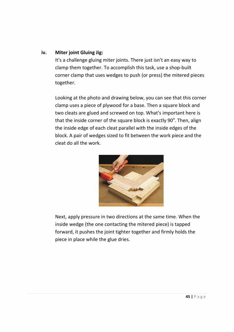
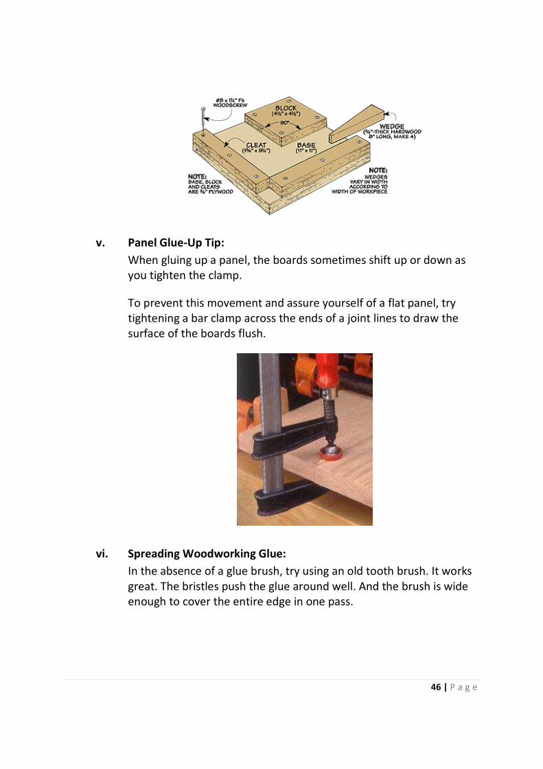
iv. Miter joint Gluing Jig:
It's a challenge gluing miter joints. There just isn't an easy way to
clamp them together. To accomplish this task, use a shop-built
corner clamp that uses wedges to push (or press) the mitered pieces
together.
Looking at the photo and drawing below, you can see that this corner
clamp uses a piece of plywood for a base. Then a square block and
two cleats are glued and screwed on top. What's important here is
that the inside corner of the square block is exactly 90o. Then, align
the inside edge of each cleat parallel with the inside edges of the
block. A pair of wedges sized to fit between the work piece and the
cleat do all the work.
Next, apply pressure in two directions at the same time. When the
inside wedge (the one contacting the mitered piece) is tapped
forward, it pushes the joint tighter together and firmly holds the
piece in place while the glue dries.
46 | P a g e
v. Panel Glue-Up Tip:
When gluing up a panel, the boards sometimes shift up or down as
you tighten the clamp.
To prevent this movement and assure yourself of a flat panel, try
tightening a bar clamp across the ends of a joint lines to draw the
surface of the boards flush.
vi. Spreading Woodworking Glue:
In the absence of a glue brush, try using an old tooth brush. It works
great. The bristles push the glue around well. And the brush is wide
enough to cover the entire edge in one pass.
47 | P a g e
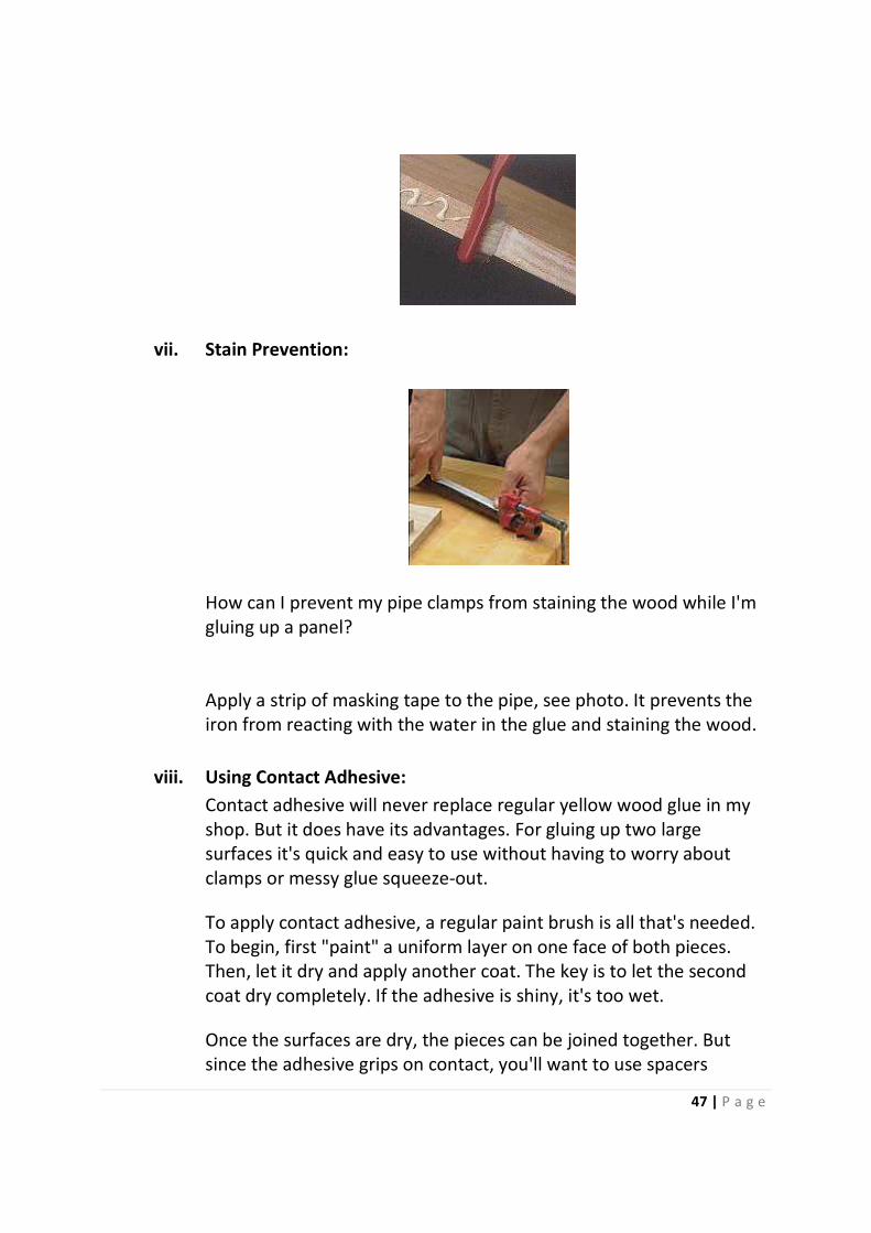
vii. Stain Prevention:
How can I prevent my pipe clamps from staining the wood while I'm
gluing up a panel?
Apply a strip of masking tape to the pipe, see photo. It prevents the
iron from reacting with the water in the glue and staining the wood.
viii. Using Contact Adhesive:
Contact adhesive will never replace regular yellow wood glue in my
shop. But it does have its advantages. For gluing up two large
surfaces it's quick and easy to use without having to worry about
clamps or messy glue squeeze-out.
To apply contact adhesive, a regular paint brush is all that's needed.
To begin, first "paint" a uniform layer on one face of both pieces.
Then, let it dry and apply another coat. The key is to let the second
coat dry completely. If the adhesive is shiny, it's too wet.
Once the surfaces are dry, the pieces can be joined together. But
since the adhesive grips on contact, you'll want to use spacers

48 | P a g e
between the pieces so that the work piece can be adjusted as
needed. Lay dowels between the pieces to start with.
Then, after the work piece is where you want it, start removing the
dowels from one end. Rolling the laminate down as you go will help
create a good bond.
6. LAYOUT
i. Layout Tool:
The lay out tool is used to position lots of screws on your wood each
at the similar distance from the other with the different inset.
To mark all the screw holes the same distance from the edge of the
plywood back, first, mount a ruler on a piece of scrap wood. This
eliminated the need for a tape measure.
Secondly, cut the piece of scrap 3½″ wide and to match the length of
his ruler (12″). Then, cut a shallow rabbet along one edge to hold the
rule in position.
49 | P a g e
Ensure that you cut the width of the rabbet narrower than that of
the ruler. That way, it overhung the edge of the scrap. And the
amount of overhang equaled the inset he wanted for the position of
the screw holes.
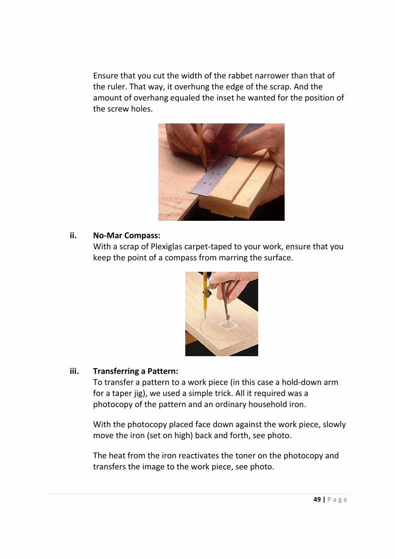
ii. No-Mar Compass:
With a scrap of Plexiglas carpet-taped to your work, ensure that you
keep the point of a compass from marring the surface.
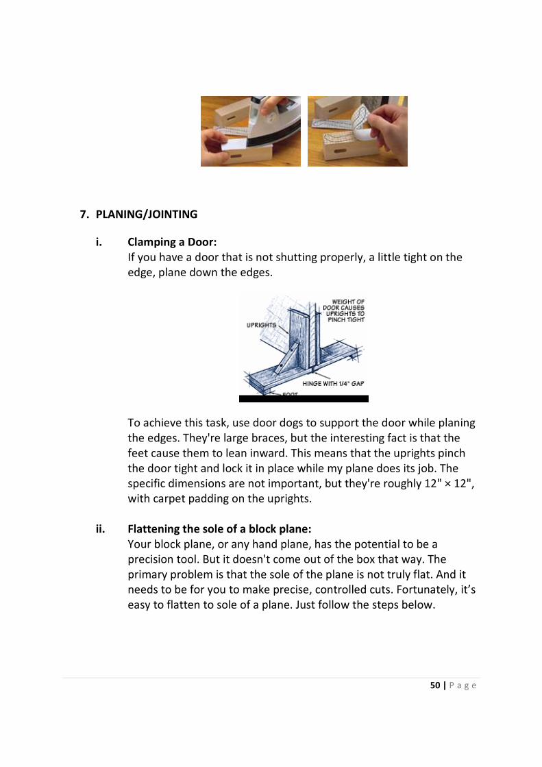
iii. Transferring a Pattern:
To transfer a pattern to a work piece (in this case a hold-down arm
for a taper jig), we used a simple trick. All it required was a
photocopy of the pattern and an ordinary household iron.
With the photocopy placed face down against the work piece, slowly
move the iron (set on high) back and forth, see photo.
The heat from the iron reactivates the toner on the photocopy and
transfers the image to the work piece, see photo.
50 | P a g e
7. PLANING/JOINTING
i. Clamping a Door:
If you have a door that is not shutting properly, a little tight on the
edge, plane down the edges.
To achieve this task, use door dogs to support the door while planing
the edges. They're large braces, but the interesting fact is that the
feet cause them to lean inward. This means that the uprights pinch
the door tight and lock it in place while my plane does its job. The
specific dimensions are not important, but they're roughly 12" × 12",
with carpet padding on the uprights.
ii. Flattening the sole of a block plane:
Your block plane, or any hand plane, has the potential to be a
precision tool. But it doesn't come out of the box that way. The
primary problem is that the sole of the plane is not truly flat. And it
needs to be for you to make precise, controlled cuts. Fortunately, it’s
easy to flatten to sole of a plane. Just follow the steps below.
51 | P a g e
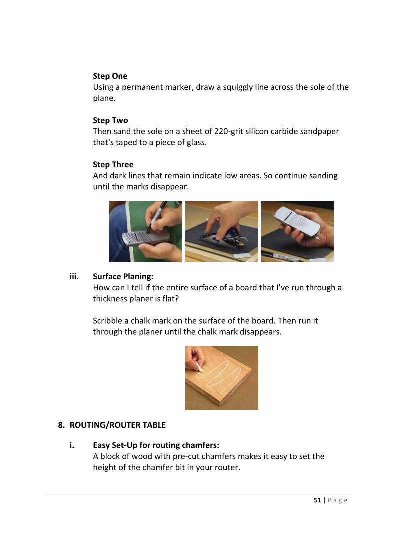
Step One
Using a permanent marker, draw a squiggly line across the sole of the
plane.
Step Two
Then sand the sole on a sheet of 220-grit silicon carbide sandpaper
that's taped to a piece of glass.
Step Three
And dark lines that remain indicate low areas. So continue sanding
until the marks disappear.
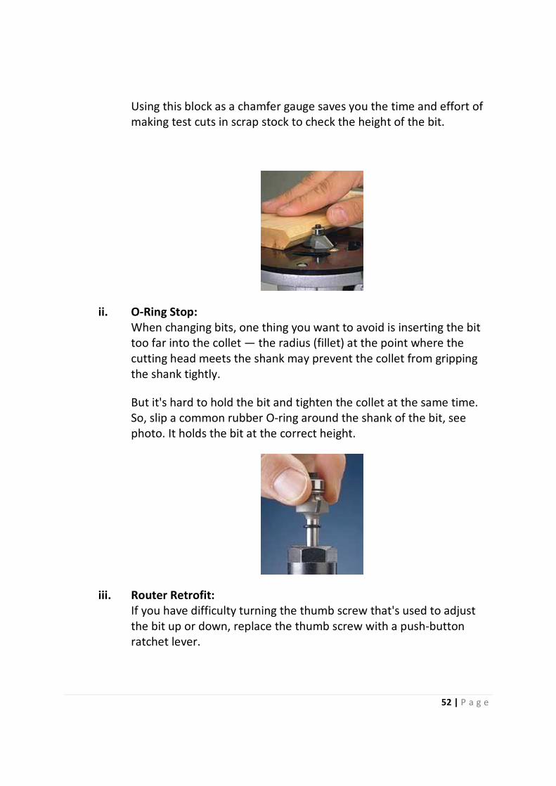
iii. Surface Planing:
How can I tell if the entire surface of a board that I've run through a
thickness planer is flat?
Scribble a chalk mark on the surface of the board. Then run it
through the planer until the chalk mark disappears.
8. ROUTING/ROUTER TABLE
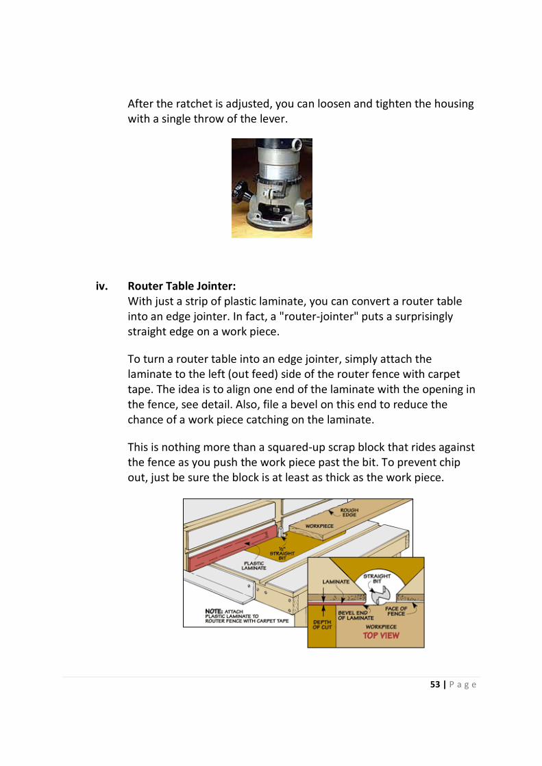
i. Easy Set-Up for routing chamfers:
A block of wood with pre-cut chamfers makes it easy to set the
height of the chamfer bit in your router.
52 | P a g e
Using this block as a chamfer gauge saves you the time and effort of
making test cuts in scrap stock to check the height of the bit.
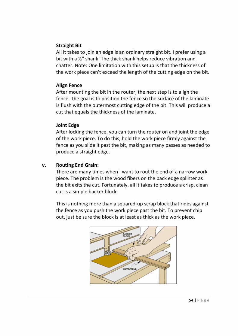
ii. O-Ring Stop:
When changing bits, one thing you want to avoid is inserting the bit
too far into the collet — the radius (fillet) at the point where the
cutting head meets the shank may prevent the collet from gripping
the shank tightly.
But it's hard to hold the bit and tighten the collet at the same time.
So, slip a common rubber O-ring around the shank of the bit, see
photo. It holds the bit at the correct height.
iii. Router Retrofit:
If you have difficulty turning the thumb screw that's used to adjust
the bit up or down, replace the thumb screw with a push-button
ratchet lever.
53 | P a g e
After the ratchet is adjusted, you can loosen and tighten the housing
with a single throw of the lever.
iv. Router Table Jointer:
With just a strip of plastic laminate, you can convert a router table
into an edge jointer. In fact, a "router-jointer" puts a surprisingly
straight edge on a work piece.
To turn a router table into an edge jointer, simply attach the
laminate to the left (out feed) side of the router fence with carpet
tape. The idea is to align one end of the laminate with the opening in
the fence, see detail. Also, file a bevel on this end to reduce the
chance of a work piece catching on the laminate.
This is nothing more than a squared-up scrap block that rides against
the fence as you push the work piece past the bit. To prevent chip
out, just be sure the block is at least as thick as the work piece.
54 | P a g e
Straight Bit
All it takes to join an edge is an ordinary straight bit. I prefer using a
bit with a ½" shank. The thick shank helps reduce vibration and
chatter. Note: One limitation with this setup is that the thickness of
the work piece can't exceed the length of the cutting edge on the bit.
Align Fence
After mounting the bit in the router, the next step is to align the
fence. The goal is to position the fence so the surface of the laminate
is flush with the outermost cutting edge of the bit. This will produce a
cut that equals the thickness of the laminate.
Joint Edge
After locking the fence, you can turn the router on and joint the edge
of the work piece. To do this, hold the work piece firmly against the
fence as you slide it past the bit, making as many passes as needed to
produce a straight edge.
v. Routing End Grain:
There are many times when I want to rout the end of a narrow work
piece. The problem is the wood fibers on the back edge splinter as
the bit exits the cut. Fortunately, all it takes to produce a crisp, clean
cut is a simple backer block.
This is nothing more than a squared-up scrap block that rides against
the fence as you push the work piece past the bit. To prevent chip
out, just be sure the block is at least as thick as the work piece.
55 | P a g e
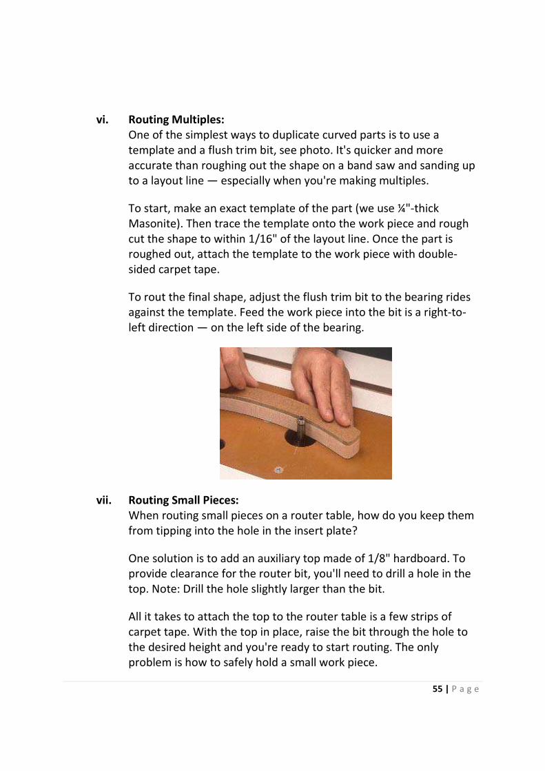
vi. Routing Multiples:
One of the simplest ways to duplicate curved parts is to use a
template and a flush trim bit, see photo. It's quicker and more
accurate than roughing out the shape on a band saw and sanding up
to a layout line — especially when you're making multiples.
To start, make an exact template of the part (we use ¼"-thick
Masonite). Then trace the template onto the work piece and rough
cut the shape to within 1/16" of the layout line. Once the part is
roughed out, attach the template to the work piece with double-
sided carpet tape.
To rout the final shape, adjust the flush trim bit to the bearing rides
against the template. Feed the work piece into the bit is a right-to-
left direction — on the left side of the bearing.
vii. Routing Small Pieces:
When routing small pieces on a router table, how do you keep them
from tipping into the hole in the insert plate?
One solution is to add an auxiliary top made of 1/8" hardboard. To
provide clearance for the router bit, you'll need to drill a hole in the
top. Note: Drill the hole slightly larger than the bit.
All it takes to attach the top to the router table is a few strips of
carpet tape. With the top in place, raise the bit through the hole to
the desired height and you're ready to start routing. The only
problem is how to safely hold a small work piece.
56 | P a g e
The best way found is to hold them with a rubber-bottom grout
trowel. This way, you can control the cut without getting my fingers
close to the bit. Note: Grout trowels are available at most hardware
stores and home centers.
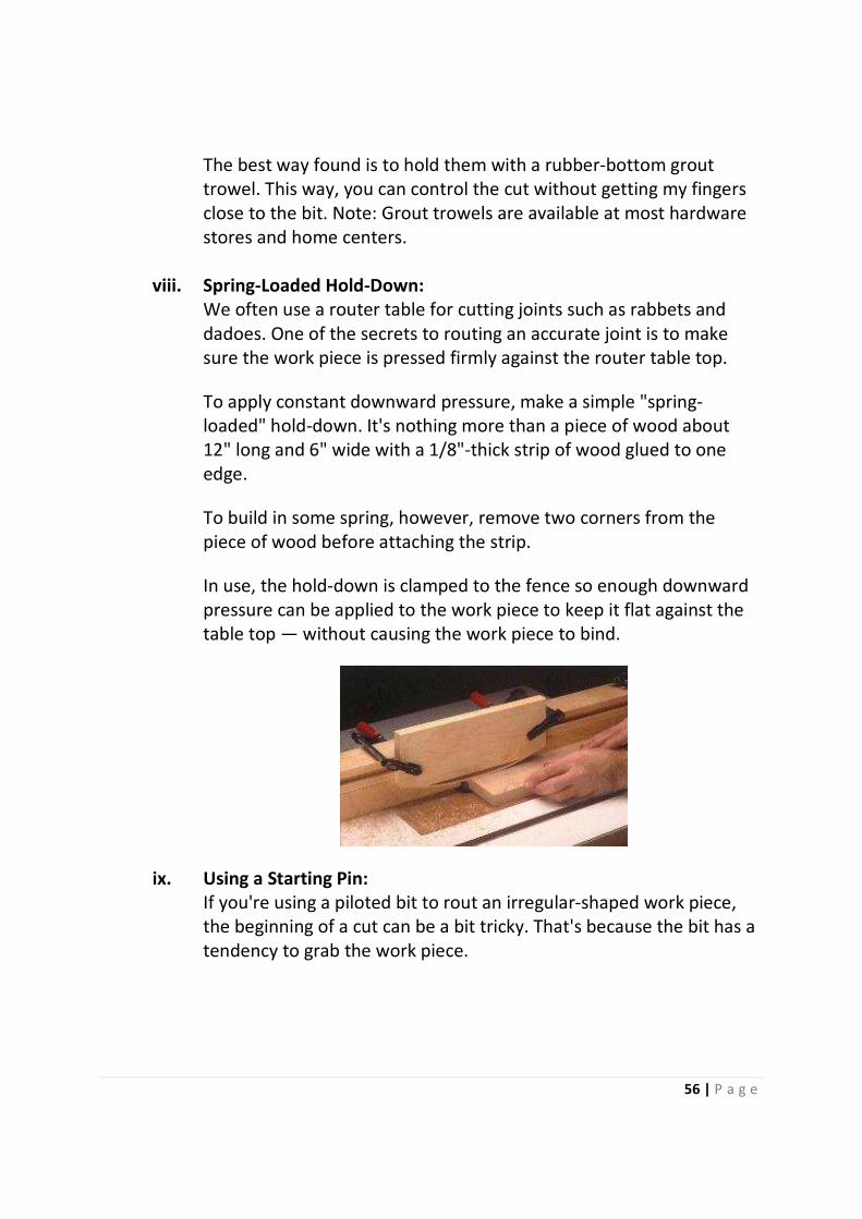
viii. Spring-Loaded Hold-Down:
We often use a router table for cutting joints such as rabbets and
dadoes. One of the secrets to routing an accurate joint is to make
sure the work piece is pressed firmly against the router table top.
To apply constant downward pressure, make a simple "spring-
loaded" hold-down. It's nothing more than a piece of wood about
12" long and 6" wide with a 1/8"-thick strip of wood glued to one
edge.
To build in some spring, however, remove two corners from the
piece of wood before attaching the strip.
In use, the hold-down is clamped to the fence so enough downward
pressure can be applied to the work piece to keep it flat against the
table top — without causing the work piece to bind.
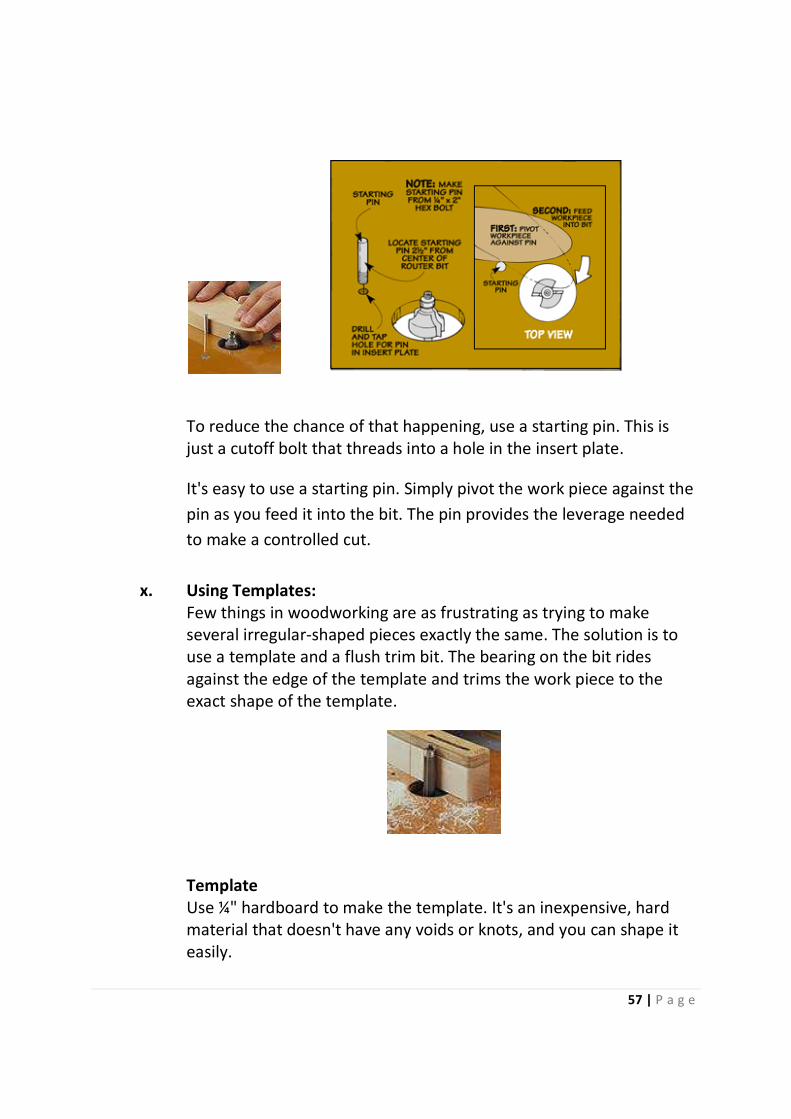
ix. Using a Starting Pin:
If you're using a piloted bit to rout an irregular-shaped work piece,
the beginning of a cut can be a bit tricky. That's because the bit has a
tendency to grab the work piece.
57 | P a g e
To reduce the chance of that happening, use a starting pin. This is
just a cutoff bolt that threads into a hole in the insert plate.
It's easy to use a starting pin. Simply pivot the work piece against the
pin as you feed it into the bit. The pin provides the leverage needed
to make a controlled cut.
x. Using Templates:
Few things in woodworking are as frustrating as trying to make
several irregular-shaped pieces exactly the same. The solution is to
use a template and a flush trim bit. The bearing on the bit rides
against the edge of the template and trims the work piece to the
exact shape of the template.
Template
Use ¼" hardboard to make the template. It's an inexpensive, hard
material that doesn't have any voids or knots, and you can shape it
easily.
58 | P a g e
To make a template, start by laying out the shape you want on the
hardboard. Or you can cut a full-size pattern out of paper and glue it
to the hardboard. Then cut out the shape slightly oversize, and file
(or sand) carefully up to the line.
Keep in mind that any notches or gouges on the edge of the template
will show up later on the finished pieces, so it's important to take the
time to work the edges smooth.
After the template is made, attach it to the work piece with carpet
tape. Then use a band saw (or sabre saw) to cut around the template
so the work piece is about 1/16" larger than the template.
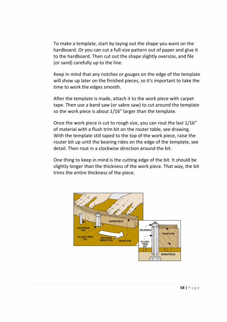
Once the work piece is cut to rough size, you can rout the last 1/16"
of material with a flush trim bit on the router table, see drawing.
With the template still taped to the top of the work piece, raise the
router bit up until the bearing rides on the edge of the template, see
detail. Then rout in a clockwise direction around the bit.
One thing to keep in mind is the cutting edge of the bit. It should be
slightly longer than the thickness of the work piece. That way, the bit
trims the entire thickness of the piece.
59 | P a g e
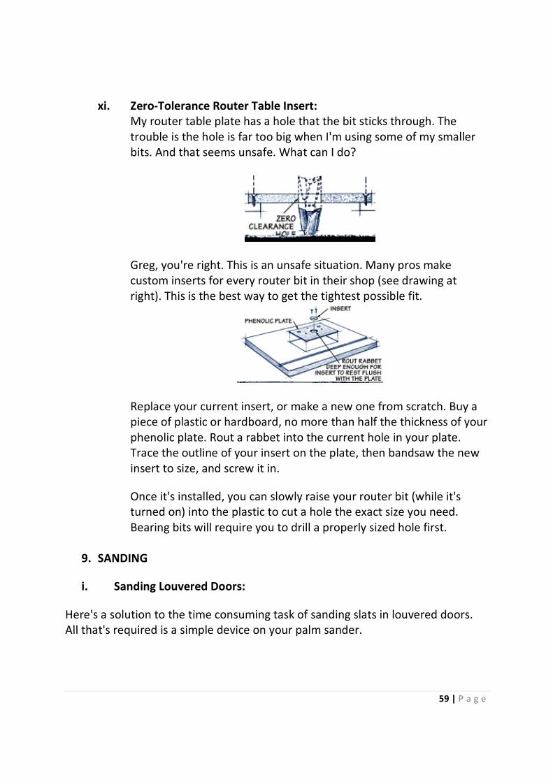
xi. Zero-Tolerance Router Table Insert:
My router table plate has a hole that the bit sticks through. The
trouble is the hole is far too big when I'm using some of my smaller
bits. And that seems unsafe. What can I do?
Greg, you're right. This is an unsafe situation. Many pros make
custom inserts for every router bit in their shop (see drawing at
right). This is the best way to get the tightest possible fit.
Replace your current insert, or make a new one from scratch. Buy a
piece of plastic or hardboard, no more than half the thickness of your
phenolic plate. Rout a rabbet into the current hole in your plate.
Trace the outline of your insert on the plate, then bandsaw the new
insert to size, and screw it in.
Once it's installed, you can slowly raise your router bit (while it's
turned on) into the plastic to cut a hole the exact size you need.
Bearing bits will require you to drill a properly sized hole first.
9. SANDING
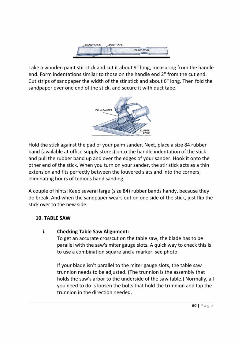
i. Sanding Louvered Doors:
Here's a solution to the time consuming task of sanding slats in louvered doors.
All that's required is a simple device on your palm sander.
60 | P a g e
Take a wooden paint stir stick and cut it about 9" long, measuring from the handle
end. Form indentations similar to those on the handle end 2" from the cut end.
Cut strips of sandpaper the width of the stir stick and about 6" long. Then fold the
sandpaper over one end of the stick, and secure it with duct tape.
Hold the stick against the pad of your palm sander. Next, place a size 84 rubber
band (available at office supply stores) onto the handle indentation of the stick
and pull the rubber band up and over the edges of your sander. Hook it onto the
other end of the stick. When you turn on your sander, the stir stick acts as a thin
extension and fits perfectly between the louvered slats and into the corners,
eliminating hours of tedious hand sanding.
A couple of hints: Keep several large (size 84) rubber bands handy, because they
do break. And when the sandpaper wears out on one side of the stick, just flip the
stick over to the new side.
10. TABLE SAW
i. Checking Table Saw Alignment:
To get an accurate crosscut on the table saw, the blade has to be
parallel with the saw's miter gauge slots. A quick way to check this is
to use a combination square and a marker, see photo.
If your blade isn't parallel to the miter gauge slots, the table saw
trunnion needs to be adjusted. (The trunnion is the assembly that
holds the saw's arbor to the underside of the saw table.) Normally, all
you need to do is loosen the bolts that hold the trunnion and tap the
trunnion in the direction needed.
61 | P a g e
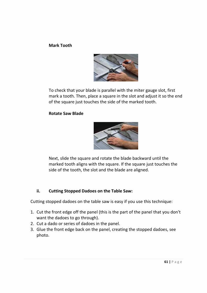
Mark Tooth
To check that your blade is parallel with the miter gauge slot, first
mark a tooth. Then, place a square in the slot and adjust it so the end
of the square just touches the side of the marked tooth.
Rotate Saw Blade
Next, slide the square and rotate the blade backward until the
marked tooth aligns with the square. If the square just touches the
side of the tooth, the slot and the blade are aligned.
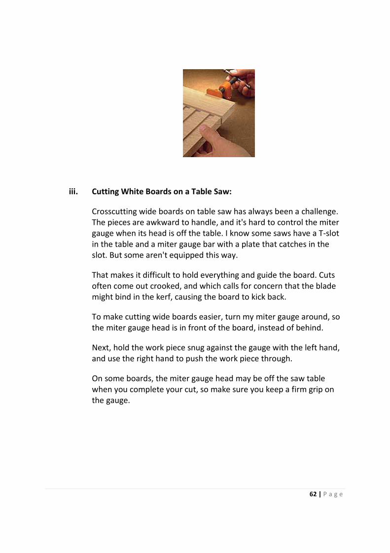
ii. Cutting Stopped Dadoes on the Table Saw:
Cutting stopped dadoes on the table saw is easy if you use this technique:
1. Cut the front edge off the panel (this is the part of the panel that you don't
want the dadoes to go through).
2. Cut a dado or series of dadoes in the panel.
3. Glue the front edge back on the panel, creating the stopped dadoes, see
photo.
62 | P a g e
iii. Cutting White Boards on a Table Saw:
Crosscutting wide boards on table saw has always been a challenge.
The pieces are awkward to handle, and it's hard to control the miter
gauge when its head is off the table. I know some saws have a T-slot
in the table and a miter gauge bar with a plate that catches in the
slot. But some aren't equipped this way.
That makes it difficult to hold everything and guide the board. Cuts
often come out crooked, and which calls for concern that the blade
might bind in the kerf, causing the board to kick back.
To make cutting wide boards easier, turn my miter gauge around, so
the miter gauge head is in front of the board, instead of behind.
Next, hold the work piece snug against the gauge with the left hand,
and use the right hand to push the work piece through.
On some boards, the miter gauge head may be off the saw table
when you complete your cut, so make sure you keep a firm grip on
the gauge.

63 | P a g e
iv. Miter Gauge Setup Jig:
Adjusting the miter gauge and testing the setup usually takes a bit of
time. To save time, use a simple jig that allows to quickly and
accurately set the miter gauge to both 90° and C.
To make the setup jig, all you need is a scrap piece of plywood. (Mine
was 8" × 12".) The first thing to do with this piece is to rip both sides
so they're parallel.
Next, cut one end of the jig at 90° and cut the other end at 45°. These
cut must be accurate, so take your time. After all, if they're off, even
slightly, then your miter gauge will always be off, and the jig won't be
much help.
When the ends are cut, all that's left to do is to cut two grooves sized
to hold the bar of your miter gauge. (I made mine ½" deep.) Cut one
groove on each face, offsetting them so as not to create a weak point
in the jig. Cut two grooves so that you can set the jig to a 45° angle in
either direction. To set the jig to 90°, simply use the square end.
64 | P a g e
PROJECTS
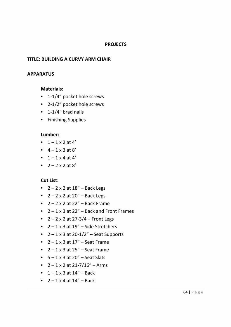
TITLE: BUILDING A CURVY ARM CHAIR
APPARATUS
Materials:
• 1-1/4” pocket hole screws
• 2-1/2” pocket hole screws
• 1-1/4” brad nails
• Finishing Supplies
Lumber:
• 1 – 1 x 2 at 4’
• 4 – 1 x 3 at 8’
• 1 – 1 x 4 at 4’
• 2 – 2 x 2 at 8’
Cut List:
• 2 – 2 x 2 at 18” – Back Legs
• 2 – 2 x 2 at 20” – Back Legs
• 2 – 2 x 2 at 22” – Back Frame
• 2 – 1 x 3 at 22” – Back and Front Frames
• 2 – 2 x 2 at 27-3/4 – Front Legs
• 2 – 1 x 3 at 19” – Side Stretchers
• 2 – 1 x 3 at 20-1/2” – Seat Supports
• 2 – 1 x 3 at 17” – Seat Frame
• 2 – 1 x 3 at 25” – Seat Frame
• 5 – 1 x 3 at 20” – Seat Slats
• 2 – 1 x 2 at 21-7/16” – Arms
• 1 – 1 x 3 at 14” – Back
• 2 – 1 x 4 at 14” – Back
PROCEDURE
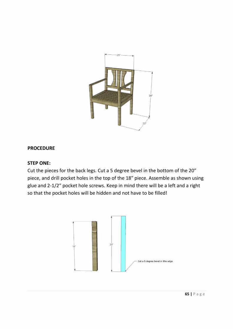
STEP ONE:
Cut the pieces for the back legs. Cut a 5 degree
piece, and drill pocket holes in the top of the 18
glue and 2-1/2″ pocket hole screws. Keep in mind there will be a left an
so that the pocket holes will be hidden and not have to be filled!
Cut the pieces for the back legs. Cut a 5 degree bevel in the bottom of the 20
piece, and drill pocket holes in the top of the 18″ piece. Assemble as shown using
″ pocket hole screws. Keep in mind there will be a left an
so that the pocket holes will be hidden and not have to be filled!
65 | P a g e
bevel in the bottom of the 20″
″ piece. Assemble as shown using
″ pocket hole screws. Keep in mind there will be a left and a right
so that the pocket holes will be hidden and not have to be filled!
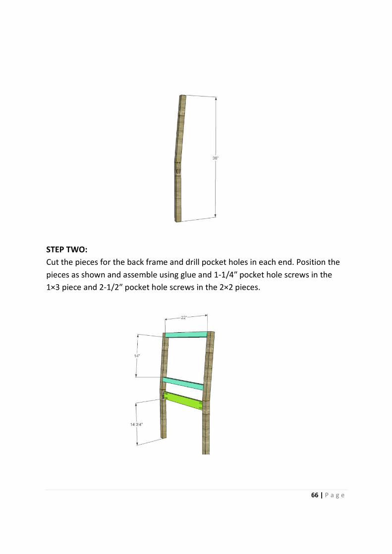
STEP TWO:
Cut the pieces for the back frame and drill pocket holes in each end. Position the
pieces as shown and assemble using glue and 1
1×3 piece and 2-1/2″ pocket hole screws in the 2×2 pieces.
Cut the pieces for the back frame and drill pocket holes in each end. Position the
pieces as shown and assemble using glue and 1-1/4″ pocket hole screws in the
″ pocket hole screws in the 2×2 pieces.
66 | P a g e
Cut the pieces for the back frame and drill pocket holes in each end. Position the
″ pocket hole screws in the
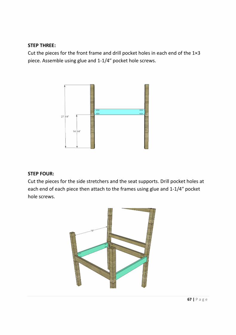
STEP THREE:
Cut the pieces for the front frame and drill pocket holes in each end of the 1×3
piece. Assemble using glue and 1
STEP FOUR:
Cut the pieces for the side stretchers and the seat supports. Drill pocket holes at
each end of each piece then attach to the frames using glue and 1
hole screws.
Cut the pieces for the front frame and drill pocket holes in each end of the 1×3
piece. Assemble using glue and 1-1/4″ pocket hole screws.
e stretchers and the seat supports. Drill pocket holes at
each end of each piece then attach to the frames using glue and 1
67 | P a g e
Cut the pieces for the front frame and drill pocket holes in each end of the 1×3
e stretchers and the seat supports. Drill pocket holes at
each end of each piece then attach to the frames using glue and 1-1/4″ pocket
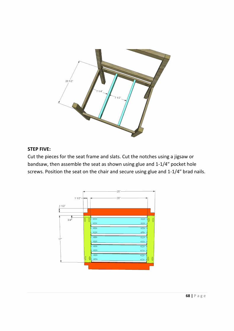
STEP FIVE:
Cut the pieces for the seat frame and slats. Cut the notches using a jigsaw or
bandsaw, then assemble the seat as shown using glue and 1
screws. Position the seat on the chair and secure using glue and 1
Cut the pieces for the seat frame and slats. Cut the notches using a jigsaw or
then assemble the seat as shown using glue and 1-1/4
screws. Position the seat on the chair and secure using glue and 1
68 | P a g e
Cut the pieces for the seat frame and slats. Cut the notches using a jigsaw or
1/4″ pocket hole
screws. Position the seat on the chair and secure using glue and 1-1/4″ brad nails.
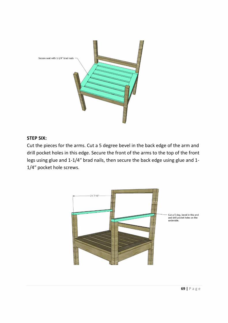
STEP SIX:
Cut the pieces for the arms. Cut a 5 degree bevel in the back edge of the arm and
drill pocket holes in this edge. Secure the front of the arms to the top of the front
legs using glue and 1-1/4″ brad nails, then secure the back edge using glue and 1
1/4″ pocket hole screws.
Cut the pieces for the arms. Cut a 5 degree bevel in the back edge of the arm and
ocket holes in this edge. Secure the front of the arms to the top of the front
″ brad nails, then secure the back edge using glue and 1
69 | P a g e
Cut the pieces for the arms. Cut a 5 degree bevel in the back edge of the arm and
ocket holes in this edge. Secure the front of the arms to the top of the front
″ brad nails, then secure the back edge using glue and 1-
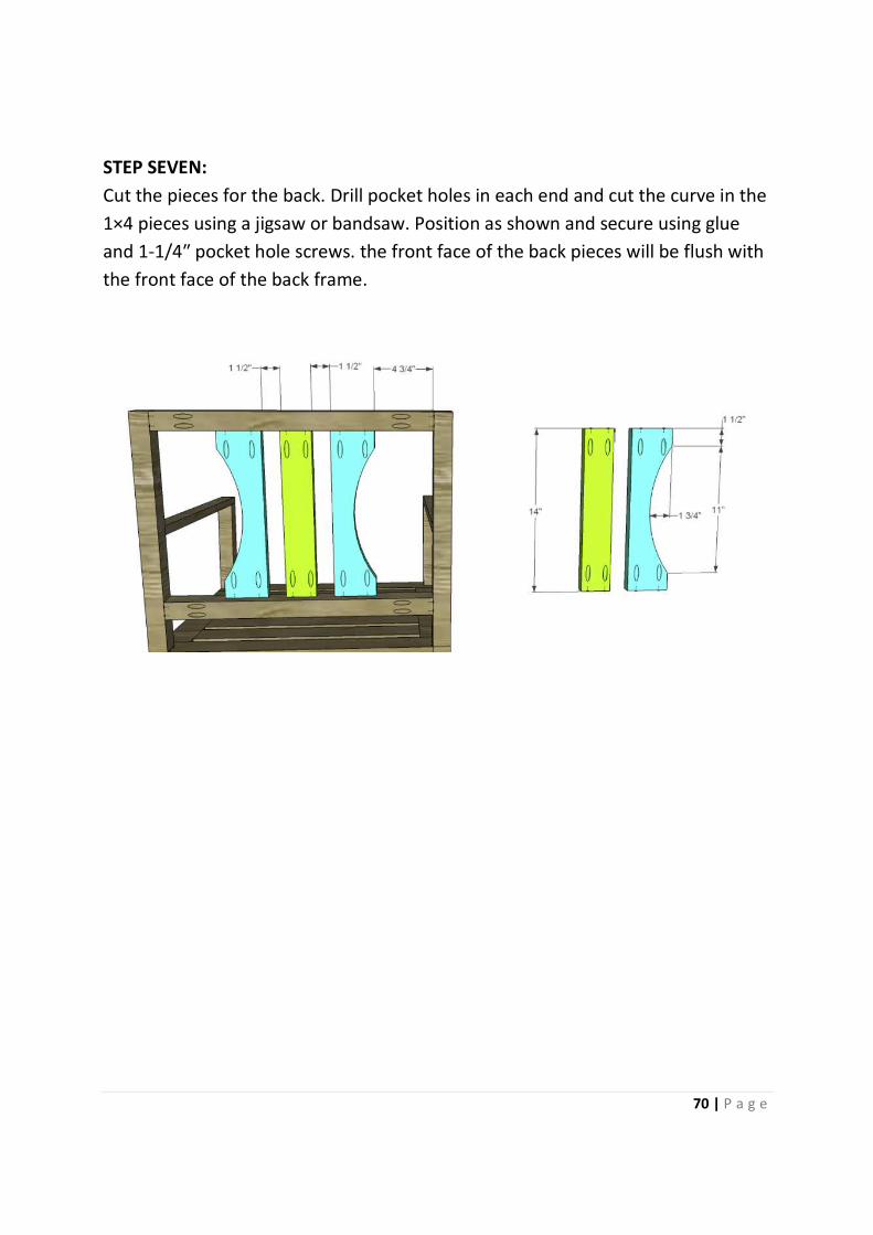
STEP SEVEN:
Cut the pieces for the back. Drill pocket holes in
1×4 pieces using a jigsaw or bandsaw. Position as shown and secure using glue
and 1-1/4″ pocket hole screws. the front face of the back pieces will be flush with
the front face of the back frame.
Cut the pieces for the back. Drill pocket holes in each end and cut the curve in the
1×4 pieces using a jigsaw or bandsaw. Position as shown and secure using glue
″ pocket hole screws. the front face of the back pieces will be flush with
the front face of the back frame.
70 | P a g e
each end and cut the curve in the
1×4 pieces using a jigsaw or bandsaw. Position as shown and secure using glue
″ pocket hole screws. the front face of the back pieces will be flush with
71 | P a g e
TITLE: BUILDING A WEATHERFORD DINING CHAIR
APPARATUS
Materials:
• 1-1/2” pocket hole screws
• 1-1/4” brad nails
• Edge branding, optional
• Wood glue
• Sandpaper (100, 150, 220 grits)
• Finishing supplies (primer and paint, or stain, sealer)
Lumber:
To build one chair:
• 1 – scrap 1 x 2 at 16”
• 1 – scrap 1 x 3 at 15”
• 1 – 1 x 4 at 6’
• 1 – scrap 1 x 6 at 15”
• 1 – scrap 1 x 10 at 12”
• 1 – 2 x 2 at 4’
• 1 – 2 x 4 at 8’
• 1 – 2’ x 2’ sheet of 3/4” plywood
Cut List:
• 2 – 2 x 4 at 39-1/2” – Back Legs
• 4 – 1 x 4 at 15” – Stretchers
• 2 – 2 x 2 at 17-1/4” – Front Legs
• 1 – 1 x 2 at 16” – Sear Support
• 1 – 1 x 3 at 15” – Back Frame
• 1 – 1 x 6 at 15” – Back Frame
• 1 – 1 x 10 at 12” – Back
72 | P a g e
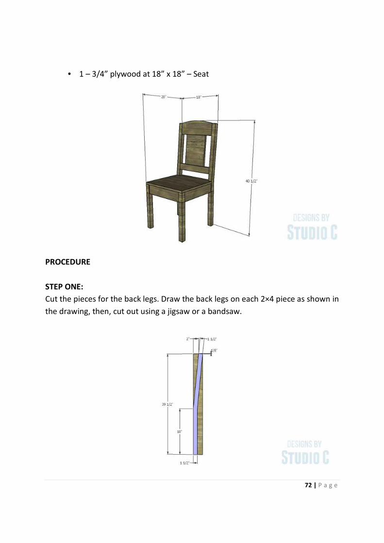
• 1 – 3/4” plywood at 18” x 18” – Seat
PROCEDURE
STEP ONE:
Cut the pieces for the back legs. Draw the back legs on each 2×4 piece as shown in
the drawing, then, cut out using a jigsaw or a bandsaw.
73 | P a g e
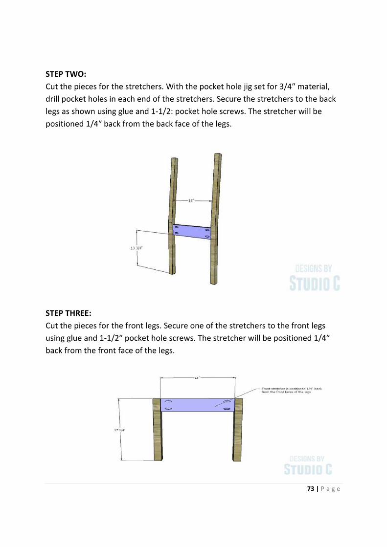
STEP TWO:
Cut the pieces for the stretchers. With the pocket hole jig set for 3/4″ material,
drill pocket holes in each end of the stretchers. Secure the stretchers to the back
legs as shown using glue and 1-1/2: pocket hole screws. The stretcher will be
positioned 1/4″ back from the back face of the legs.
STEP THREE:
Cut the pieces for the front legs. Secure one of the stretchers to the front legs
using glue and 1-1/2″ pocket hole screws. The stretcher will be positioned 1/4″
back from the front face of the legs.
74 | P a g e
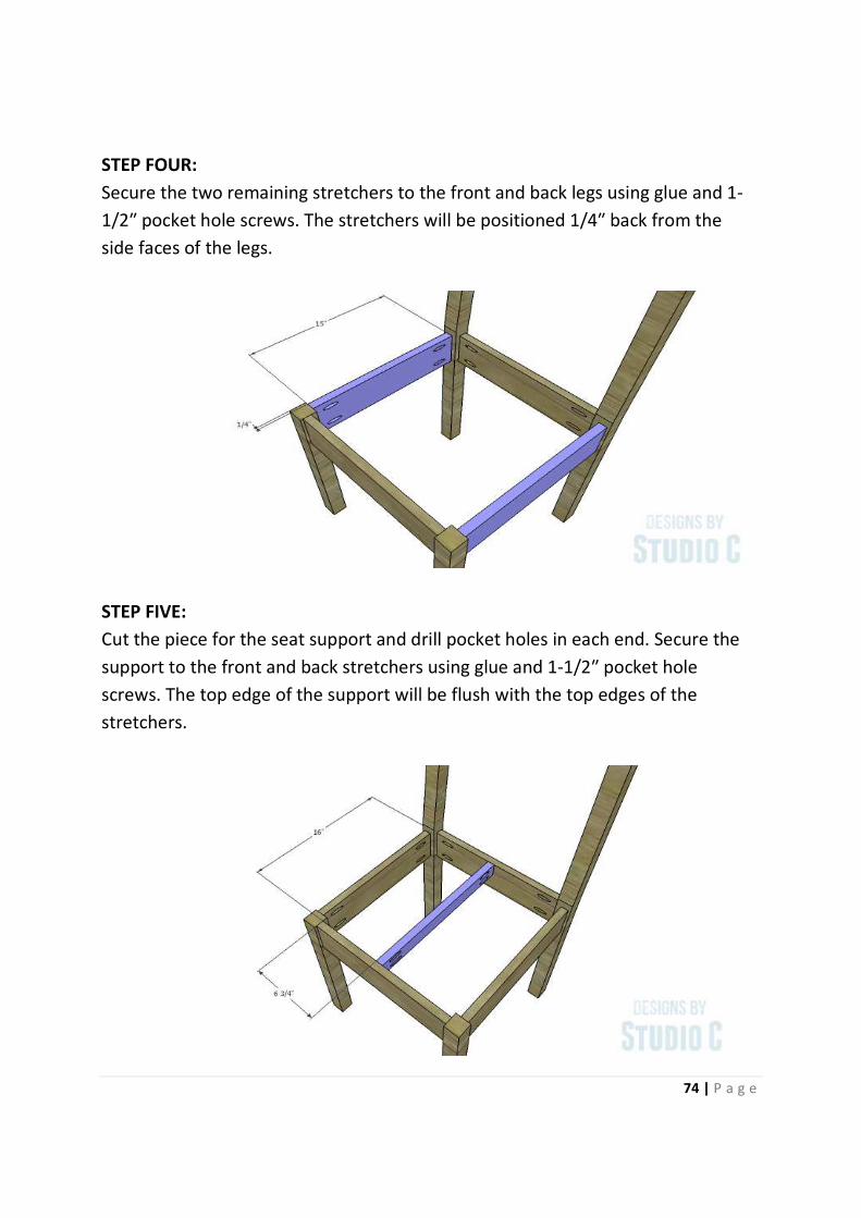
STEP FOUR:
Secure the two remaining stretchers to the front and back legs using glue and 1-
1/2″ pocket hole screws. The stretchers will be positioned 1/4″ back from the
side faces of the legs.
STEP FIVE:
Cut the piece for the seat support and drill pocket holes in each end. Secure the
support to the front and back stretchers using glue and 1-1/2″ pocket hole
screws. The top edge of the support will be flush with the top edges of the
stretchers.
75 | P a g e
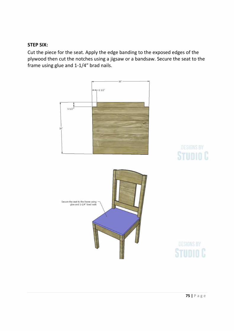
STEP SIX:
Cut the piece for the seat. Apply the edge banding to the exposed edges of the
plywood then cut the notches using a jigsaw or a bandsaw. Secure the seat to the
frame using glue and 1-1/4″ brad nails.
76 | P a g e
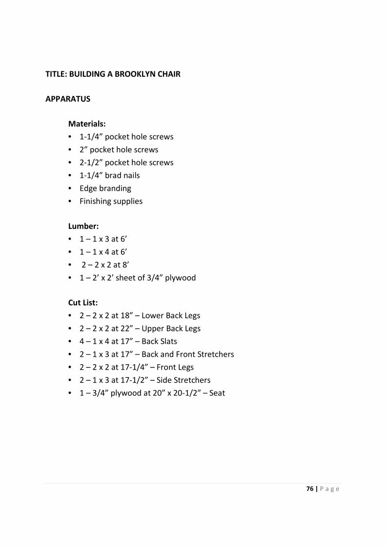
TITLE: BUILDING A BROOKLYN CHAIR
APPARATUS
Materials:
• 1-1/4” pocket hole screws
• 2” pocket hole screws
• 2-1/2” pocket hole screws
• 1-1/4” brad nails
• Edge branding
• Finishing supplies
Lumber:
• 1 – 1 x 3 at 6’
• 1 – 1 x 4 at 6’
• 2 – 2 x 2 at 8’
• 1 – 2’ x 2’ sheet of 3/4” plywood
Cut List:
• 2 – 2 x 2 at 18” – Lower Back Legs
• 2 – 2 x 2 at 22” – Upper Back Legs
• 4 – 1 x 4 at 17” – Back Slats
• 2 – 1 x 3 at 17” – Back and Front Stretchers
• 2 – 2 x 2 at 17-1/4” – Front Legs
• 2 – 1 x 3 at 17-1/2” – Side Stretchers
• 1 – 3/4” plywood at 20” x 20-1/2” – Seat
PROCEDURE:
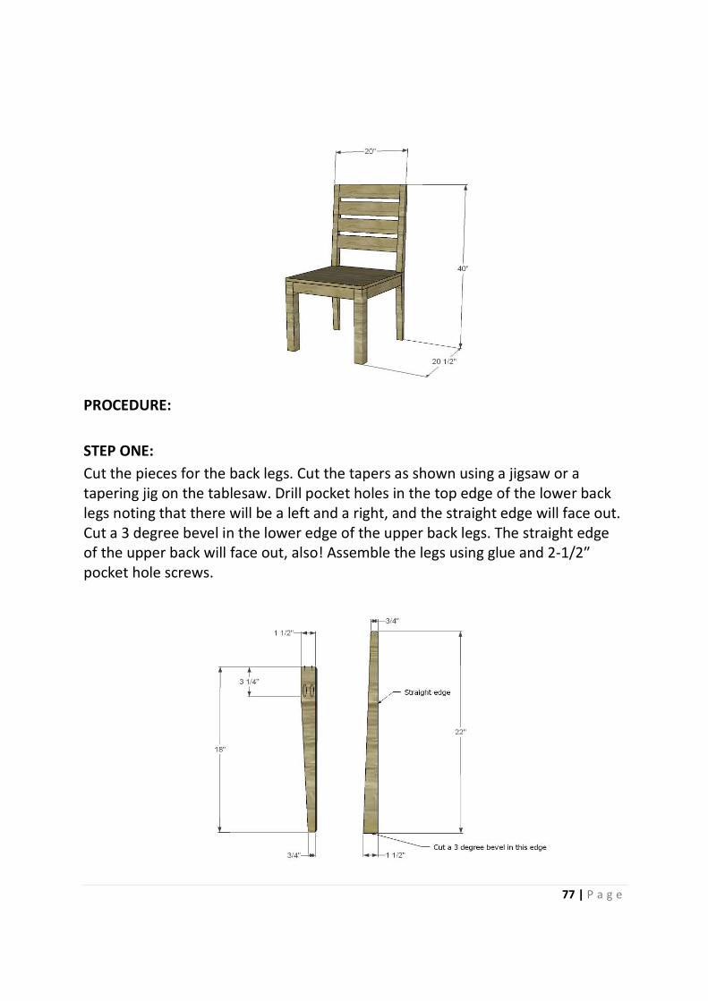
STEP ONE:
Cut the pieces for the back legs. Cut the tapers as shown using a jigsaw or a
tapering jig on the tablesaw. Drill pocket holes in the top edge of the lower back
legs noting that there will be a left and a right, and the straight edge will face out.
Cut a 3 degree bevel in the lower edge of the upper back legs. The straight edge
of the upper back will face out, also! Assemble the legs using glue and 2
pocket hole screws.
Cut the pieces for the back legs. Cut the tapers as shown using a jigsaw or a
tapering jig on the tablesaw. Drill pocket holes in the top edge of the lower back
legs noting that there will be a left and a right, and the straight edge will face out.
Cut a 3 degree bevel in the lower edge of the upper back legs. The straight edge
of the upper back will face out, also! Assemble the legs using glue and 2
77 | P a g e
Cut the pieces for the back legs. Cut the tapers as shown using a jigsaw or a
tapering jig on the tablesaw. Drill pocket holes in the top edge of the lower back
legs noting that there will be a left and a right, and the straight edge will face out.
Cut a 3 degree bevel in the lower edge of the upper back legs. The straight edge
of the upper back will face out, also! Assemble the legs using glue and 2-1/2″
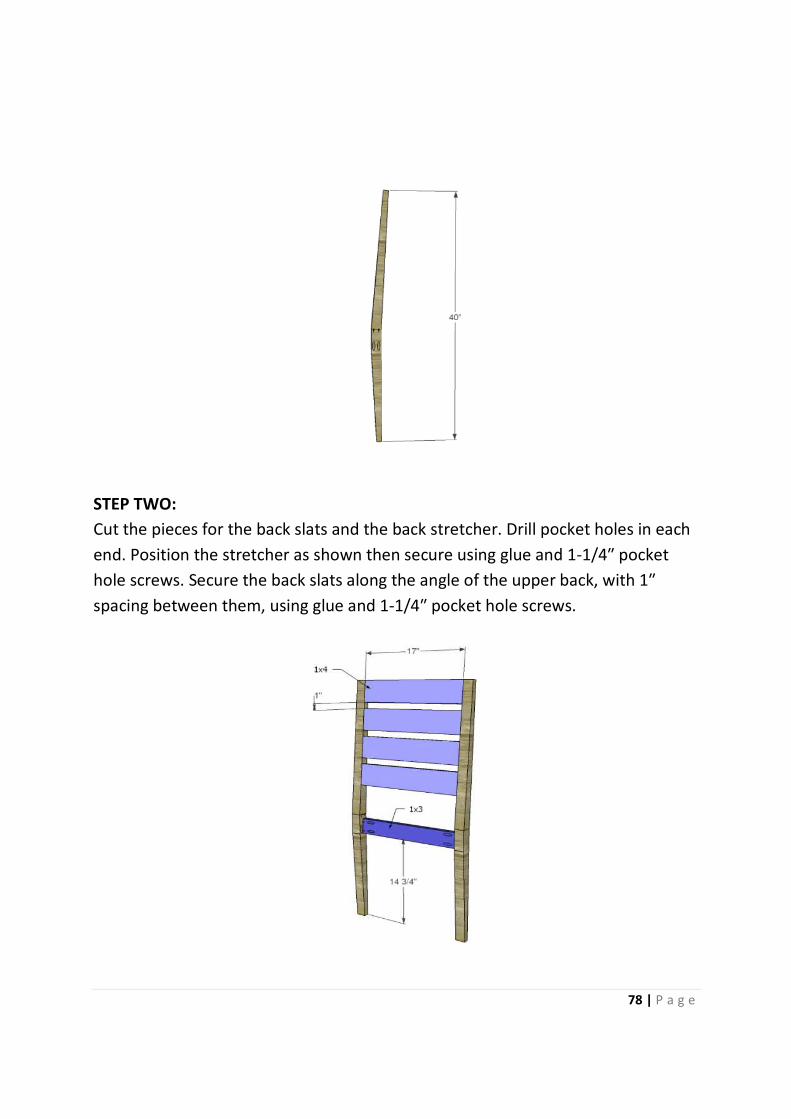
STEP TWO:
Cut the pieces for the back slats and the back stretcher. Drill pocket holes in each
end. Position the stretcher as shown then secure using glue and 1
hole screws. Secure the back slats along the angle of the upper
spacing between them, using glue and 1
Cut the pieces for the back slats and the back stretcher. Drill pocket holes in each
end. Position the stretcher as shown then secure using glue and 1
hole screws. Secure the back slats along the angle of the upper
spacing between them, using glue and 1-1/4″ pocket hole screws.
78 | P a g e
Cut the pieces for the back slats and the back stretcher. Drill pocket holes in each
end. Position the stretcher as shown then secure using glue and 1-1/4″ pocket
hole screws. Secure the back slats along the angle of the upper back, with 1″
″ pocket hole screws.
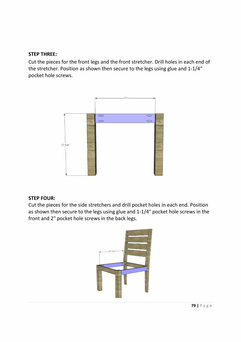
STEP THREE:
Cut the pieces for the front legs and the front stretcher. Drill holes in each end of
the stretcher. Position as shown then secure to the legs using glue and 1
pocket hole screws.
STEP FOUR:
Cut the pieces for the side stretchers and drill pocket holes in each end.
as shown then secure to the legs using glue and 1
front and 2″ pocket hole screws in the back legs.
Cut the pieces for the front legs and the front stretcher. Drill holes in each end of
the stretcher. Position as shown then secure to the legs using glue and 1
Cut the pieces for the side stretchers and drill pocket holes in each end.
as shown then secure to the legs using glue and 1-1/4″ pocket hole screws in the
″ pocket hole screws in the back legs.
79 | P a g e
Cut the pieces for the front legs and the front stretcher. Drill holes in each end of
the stretcher. Position as shown then secure to the legs using glue and 1-1/4″
Cut the pieces for the side stretchers and drill pocket holes in each end. Position
″ pocket hole screws in the
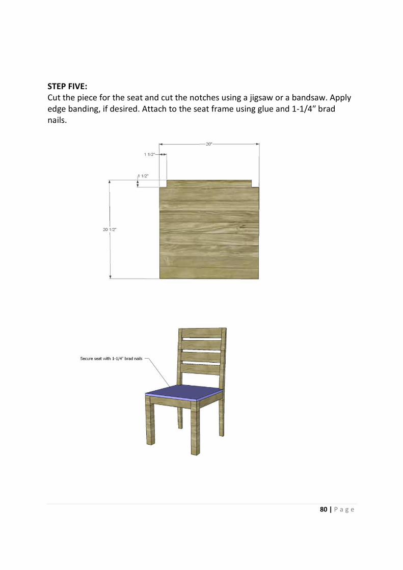
STEP FIVE:
Cut the piece for the seat and cut the notches using a jigsaw or a bandsaw. Apply
edge banding, if desired. Attach to the seat frame using glue and 1
nails.
Cut the piece for the seat and cut the notches using a jigsaw or a bandsaw. Apply
edge banding, if desired. Attach to the seat frame using glue and 1
80 | P a g e
Cut the piece for the seat and cut the notches using a jigsaw or a bandsaw. Apply
edge banding, if desired. Attach to the seat frame using glue and 1-1/4″ brad

81 | P a g e
TITLE: BUILDING THE 19TH
CENTURY AMERICAN WARDROPE
APPARATUS
Materials:
• 1-1/4” pocket hole screws
• 1-1/4” brad nails
• Edge banding for plywood, optional
• Closet rod for the cabinet
• 2 sets of 18” drawer slides
• Cabinet pulls
• 2 magnetic catches
• Finishing supplies
Lumber:
• 3 – 1 x 2 at 8’
• 8 – 1 x 3 at 8’
• 2 – 1 x 6 at 8’
• One sheet of 1/2” plywood
• One sheet of 3/4” plywood
Cut List:
• 4 – 1 x 3 at 79-3/4” – Side Frame
• 4 – 1 x 6 at 19-1/2” – Side Frame
• 2 – 1 x 2 at 64-3/4” – Side Frame
• 4 – 1/2” plywood at 9” x 64-3/4” – Side Panels
• 1 – 3/4” plywood at 44” x 75-3/4” – Back
• 1 – 1 x 2 at 44” – Lower Stretcher
• 1 – 1 x 6 at 44” – Upper Stretcher
• 1 – 3/4” plywood at 19-1/2” x 47-1/2” – Bottom
• 2 – 1/2 at 19-1/2” – Slide Supports
• 1 – 3/4” plywood at 5-3/4” x 20-1/4” – Drawer Divider
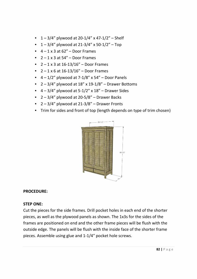
• 1 – 3/4” plywood at 20
• 1 – 3/4” plywood at 21
• 4 – 1 x 3 at 62” –
• 2 – 1 x 3 at 54” –
• 2 – 1 x 3 at 16-13/16”
• 2 – 1 x 6 at 16-13/16”
• 4 – 1/2” plywood at 7
• 2 – 3/4” plywood at 18” x 19
• 4 – 3/4” plywood at 5
• 2 – 3/4” plywood at 20
• 2 – 3/4” plywood at 21
• Trim for sides and front of top (length depends on type of trim chosen)
PROCEDURE:
STEP ONE:
Cut the pieces for the side frames. Drill pocket holes in each end of the shorter
pieces, as well as the plywood panels as shown. The 1x3s for the sides of the
frames are positioned on end and the other frame pieces will be flush with the
outside edge. The panels will be flush with the inside face of the shorter frame
pieces. Assemble using glue and 1
3/4” plywood at 20-1/4” x 47-1/2” – Shelf
4” plywood at 21-3/4” x 50-1/2” – Top
– Door Frames
– Door Frames
13/16” – Door Frames
13/16” – Door Frames
1/2” plywood at 7-1/8” x 54” – Door Panels
3/4” plywood at 18” x 19-1/8” – Drawer Bottoms
3/4” plywood at 5-1/2” x 18” – Drawer Sides
3/4” plywood at 20-5/8” – Drawer Backs
3/4” plywood at 21-3/8” – Drawer Fronts
Trim for sides and front of top (length depends on type of trim chosen)
e pieces for the side frames. Drill pocket holes in each end of the shorter
pieces, as well as the plywood panels as shown. The 1x3s for the sides of the
frames are positioned on end and the other frame pieces will be flush with the
s will be flush with the inside face of the shorter frame
pieces. Assemble using glue and 1-1/4″ pocket hole screws.
82 | P a g e
Trim for sides and front of top (length depends on type of trim chosen)
e pieces for the side frames. Drill pocket holes in each end of the shorter
pieces, as well as the plywood panels as shown. The 1x3s for the sides of the
frames are positioned on end and the other frame pieces will be flush with the
s will be flush with the inside face of the shorter frame

STEP TWO:
Cut the piece for the back and drill pocket holes as shown. Secure to the side
frames using glue and 1-1/4
Cut the piece for the back and drill pocket holes as shown. Secure to the side
1/4″ pocket hole screws.
83 | P a g e
Cut the piece for the back and drill pocket holes as shown. Secure to the side
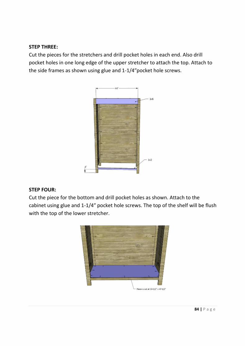
STEP THREE:
Cut the pieces for the stretchers and drill pocket holes in each end. Also drill
pocket holes in one long edge of the upper stretcher to attach the top. Attach to
the side frames as shown using glue and 1
STEP FOUR:
Cut the piece for the bottom and drill pocket holes as shown. Attach to the
cabinet using glue and 1-1/4
with the top of the lower stretcher.
Cut the pieces for the stretchers and drill pocket holes in each end. Also drill
pocket holes in one long edge of the upper stretcher to attach the top. Attach to
the side frames as shown using glue and 1-1/4″pocket hole screws.
Cut the piece for the bottom and drill pocket holes as shown. Attach to the
1/4″ pocket hole screws. The top of the shelf will be flush
with the top of the lower stretcher.
84 | P a g e
Cut the pieces for the stretchers and drill pocket holes in each end. Also drill
pocket holes in one long edge of the upper stretcher to attach the top. Attach to
″pocket hole screws.
Cut the piece for the bottom and drill pocket holes as shown. Attach to the
″ pocket hole screws. The top of the shelf will be flush
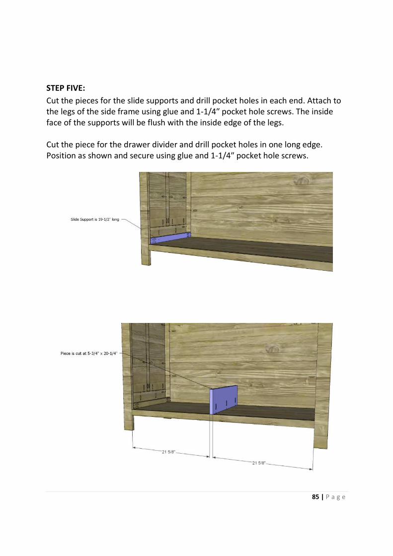
STEP FIVE:
Cut the pieces for the slide
the legs of the side frame using glue and 1
face of the supports will be flush with the inside edge of the legs.
Cut the piece for the drawer divider and drill pock
Position as shown and secure using glue and 1
Cut the pieces for the slide supports and drill pocket holes in each end. Attach to
the legs of the side frame using glue and 1-1/4″ pocket hole screws. The inside
face of the supports will be flush with the inside edge of the legs.
Cut the piece for the drawer divider and drill pocket holes in one long edge.
Position as shown and secure using glue and 1-1/4″ pocket hole screws.
85 | P a g e
supports and drill pocket holes in each end. Attach to
″ pocket hole screws. The inside
face of the supports will be flush with the inside edge of the legs.
et holes in one long edge.
″ pocket hole screws.
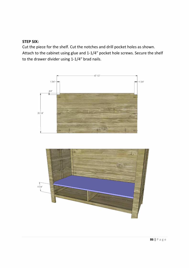
STEP SIX:
Cut the piece for the shelf. Cut the notches and drill pocket holes as shown.
Attach to the cabinet using glue and 1
to the drawer divider using 1
Cut the piece for the shelf. Cut the notches and drill pocket holes as shown.
Attach to the cabinet using glue and 1-1/4″ pocket hole screws.
to the drawer divider using 1-1/4″ brad nails.
86 | P a g e
Cut the piece for the shelf. Cut the notches and drill pocket holes as shown.
″ pocket hole screws. Secure the shelf
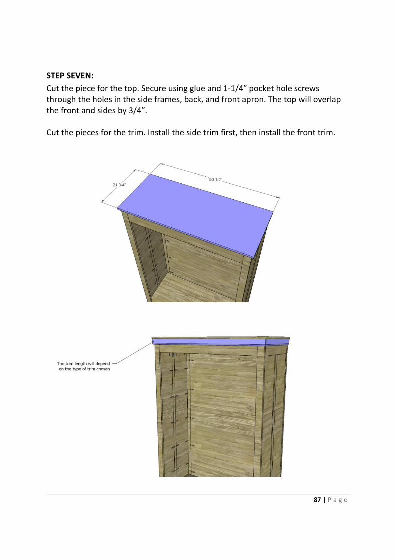
STEP SEVEN:
Cut the piece for the top. Secure using glue and 1
through the holes in the side frames, back, and front apron. The top will overlap
the front and sides by 3/4
Cut the pieces for the trim. Install the side trim first, then install the front trim.
Cut the piece for the top. Secure using glue and 1-1/4″ pocket hole screws
through the holes in the side frames, back, and front apron. The top will overlap
sides by 3/4″.
Cut the pieces for the trim. Install the side trim first, then install the front trim.
87 | P a g e
″ pocket hole screws
through the holes in the side frames, back, and front apron. The top will overlap
Cut the pieces for the trim. Install the side trim first, then install the front trim.
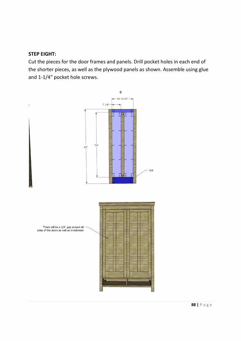
STEP EIGHT:
Cut the pieces for the door frames and panels.
the shorter pieces, as well as the plywood panels as
and 1-1/4″ pocket hole screws.
Cut the pieces for the door frames and panels. Drill pocket holes in each end of
the shorter pieces, as well as the plywood panels as shown. Assemble using glue
″ pocket hole screws.
e
88 | P a g e
Drill pocket holes in each end of
shown. Assemble using glue
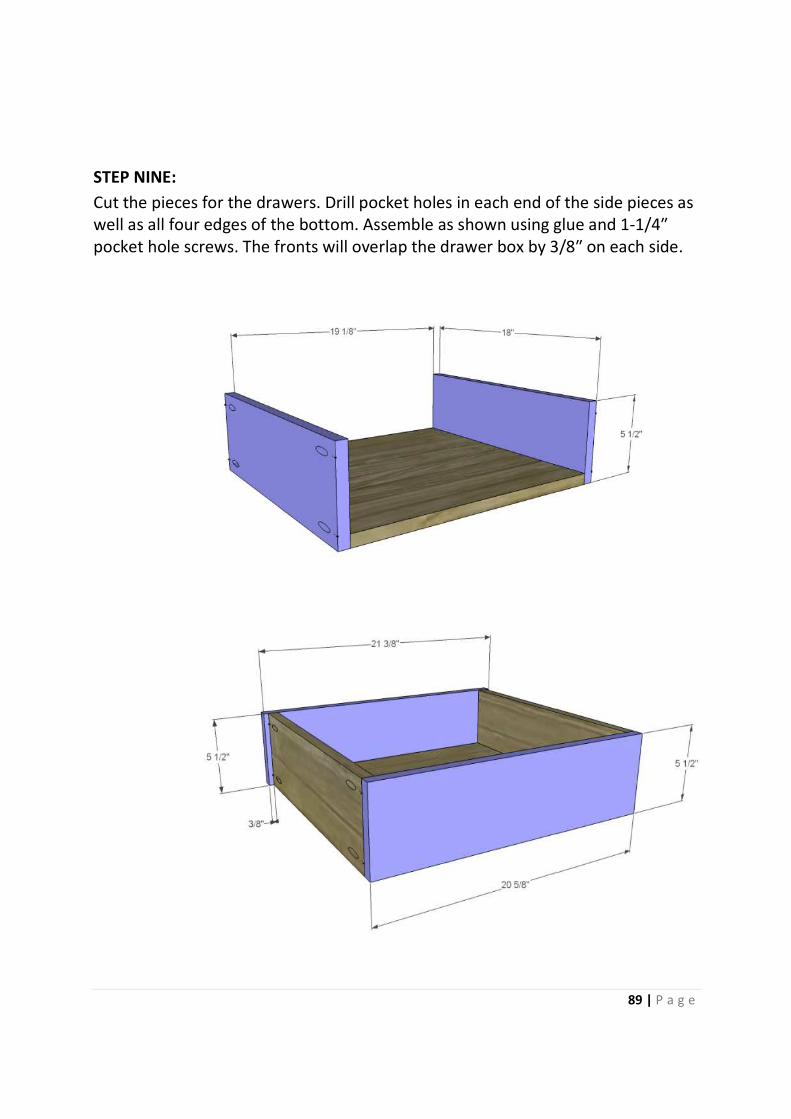
STEP NINE:
Cut the pieces for the drawers. Drill pocket holes in each end of the side pieces as
well as all four edges of the bottom. Assemble as shown using glue and 1
pocket hole screws. The fronts will overlap the drawer box by 3/8
Cut the pieces for the drawers. Drill pocket holes in each end of the side pieces as
well as all four edges of the bottom. Assemble as shown using glue and 1
screws. The fronts will overlap the drawer box by 3/8
89 | P a g e
Cut the pieces for the drawers. Drill pocket holes in each end of the side pieces as
well as all four edges of the bottom. Assemble as shown using glue and 1-1/4″
screws. The fronts will overlap the drawer box by 3/8″ on each side.
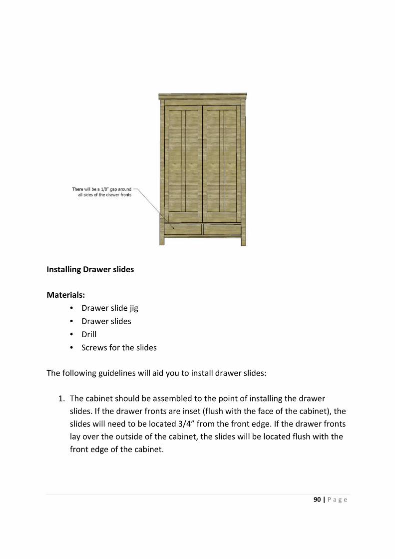
Installing Drawer slides
Materials:
• Drawer slide jig
• Drawer slides
• Drill
• Screws for the slides
The following guidelines will aid you to install drawer slides
1. The cabinet should be assembled to the point of installing the drawer
slides. If the drawer fronts are inset (flush with the face of the cabinet), the
slides will need to be located 3/4” from the front edge. If the drawer fronts
lay over the outside of the cabinet, th
front edge of the cabinet.
Screws for the slides
The following guidelines will aid you to install drawer slides:
should be assembled to the point of installing the drawer
slides. If the drawer fronts are inset (flush with the face of the cabinet), the
slides will need to be located 3/4” from the front edge. If the drawer fronts
lay over the outside of the cabinet, the slides will be located flush with the
front edge of the cabinet.
90 | P a g e
should be assembled to the point of installing the drawer
slides. If the drawer fronts are inset (flush with the face of the cabinet), the
slides will need to be located 3/4” from the front edge. If the drawer fronts
e slides will be located flush with the
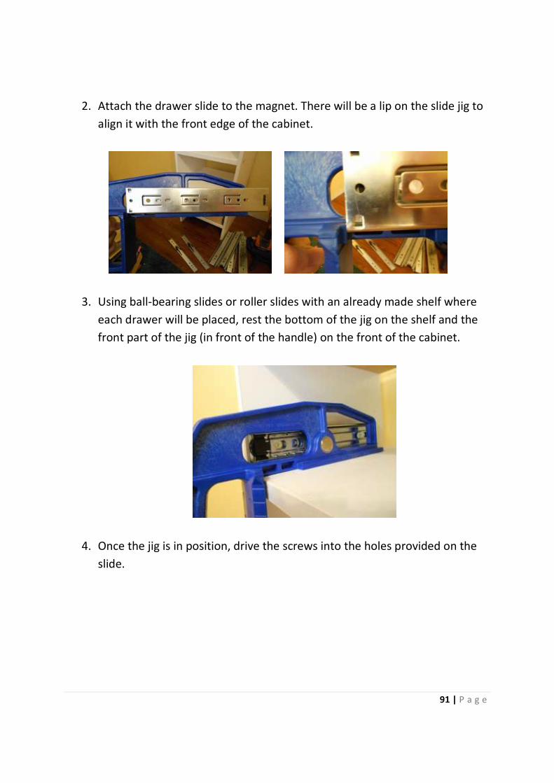
91 | P a g e
2. Attach the drawer slide to the magnet. There will be a lip on the slide jig to
align it with the front edge of the cabinet.
3. Using ball-bearing slides or roller slides with an already made shelf where
each drawer will be placed, rest the bottom of the jig on the shelf and the
front part of the jig (in front of the handle) on the front of the cabinet.
4. Once the jig is in position, drive the screws into the holes provided on the
slide.
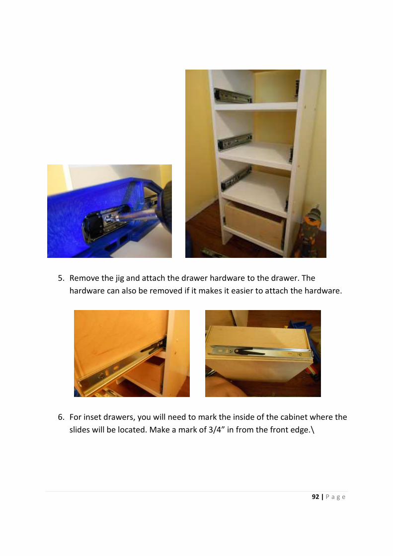
92 | P a g e
5. Remove the jig and attach the drawer hardware to the drawer. The
hardware can also be removed if it makes it easier to attach the hardware.
6. For inset drawers, you will need to mark the inside of the cabinet where the
slides will be located. Make a mark of 3/4” in from the front edge.\

93 | P a g e
7. Attach the cabinet-side hardware to the jig. Position the jig and slide so
they line up with the marks, and drive the screws. Repeat for all cabinet-
side slides.
8. Attach the drawer-side hardware to the bottom of the drawer and make
any necessary adjustments.


![arXiv:1502.07674v4 [math.CO] 23 Jun 2016 · PDF filewith block-interchanges. Keywords Plane ... introduce plane permutations, p=(s,π), study ... recurrences on plane permutations](https://img.pdfslide.net/doc/110x75/5ab743bd7f8b9a684c8b5200/arxiv150207674v4-mathco-23-jun-2016-block-interchanges-keywords-plane-.jpg)