Embed Size (px)
Citation preview

Loughborough UniversityInstitutional Repository
Federated Sensor Networkarchitectural design for theInternet of Things (IoT)
This item was submitted to Loughborough University's Institutional Repositoryby the/an author.
Additional Information:
• A Doctoral Thesis. Submitted in partial fulfilment of the requirementsfor the award of Doctor of Philosophy of Loughborough University.
Metadata Record: https://dspace.lboro.ac.uk/2134/13453
Publisher: c© Ran Xu
Please cite the published version.

This item was submitted to Loughborough’s Institutional Repository (https://dspace.lboro.ac.uk/) by the author and is made available under the
following Creative Commons Licence conditions.
For the full text of this licence, please go to: http://creativecommons.org/licenses/by-nc-nd/2.5/

Federated Sensor Network architectural design for the Internet
of Things (IoT)
by
Ran Xu
A Doctoral Thesis
Submitted in partial fulfillment
Of the requirements for the award of
Doctor of Philosophy
Of
Loughborough University
July 2013
by Ran Xu

Acknowledgement
i
Acknowledgement
This thesis would not have been possible without the guidance and the help of several
individuals who in one way or another contributed and extended their valuable
assistance in the preparation and completion of this study.
I would like to express the deepest appreciation to my supervisor, Professor
Shuang-Hua Yang, who has the attitude and the substance of a genius he continually
and convincingly conveyed a spirit of adventure in regard to research, and an
excitement in regard to teaching.
I am highly indebted to Lili Yang, Liang Du and Weiwei He for their guidance as well
as for providing necessary information regarding this research from different views.
My thanks and appreciations also go to my colleagues: Huanjia Yang, Xin Lu, Fang
Yao, Xinwei Yao, Kai Cao, Xin Ma, Hesham Abusaimeh, Tareq Alhmidea, Zaid Bin
Ahmad, and Hakan Koyuncu. These people have willingly helped me out with their
abilities.
Last but not the least, I would like to give my greatly thanks to my family for their
understanding, endless patience and encouragement.
Thank you all!

Abstract
ii
Abstract
An information technology that can combine the physical world and virtual world is
desired. The Internet of Things (IoT) is a concept system that uses Radio Frequency
Identification (RFID), WSN and barcode scanners to sense and to detect physical
objects and events. This information is shared with people on the Internet. With the
announcement of the “Smarter Planet” concept by IBM, the problem of how to share
this data was raised. However, the original design of WSN aims to provide
environment monitoring and control within a small scale local network. It cannot
meet the demands of the IoT because there is a lack of multi-connection functionality
with other WSNs and upper level applications. As various standards of WSNs provide
information for different purposes, a hybrid system that gives a complete answer by
combining all of them could be promising for future IoT applications.
This thesis is on the subject of `Federated Sensor Network' design and architectural
development for the Internet of Things. A Federated Sensor Network (FSN) is a
system that integrates WSNs and the Internet. Currently, methods of integrating
WSNs and the Internet can follow one of three main directions: a Front-End Proxy
solution, a Gateway solution or a TCP/IP Overlay solution. Architectures based on the
ideas from all three directions are presented in this thesis; this forms a comprehensive
body of research on possible Federated Sensor Network architecture designs. In

Abstract
iii
addition, a fully compatible technology for the sensor network application, namely the
Sensor Model Language (SensorML), has been reviewed and embedded into our FSN
systems. The IoT as a new concept is also comprehensively described and the major
technical issues discussed. Finally, a case study of the IoT in logistic management for
emergency response is given. Proposed FSN architectures based on the Gateway
solution are demonstrated through hardware implementation and lab tests. A
demonstration of the 6LoWPAN enabled federated sensor network based on the
TCP/IP Overlay solution presents a good result for the iNET localization and tracking
project. All the tests of the designs have verified feasibility and achieve the target of
the IoT concept.

Publications
iv
Publications
Conference Publications:
• Xu, R., Yang, S.H., “Federated Wireless Sensor Network”, The Proceeding of
the 15th CACSUK, Luton, UK, 2009. ISBN 978-0-9555293-4-4.
• Xu, R., Yang, S.H., “Distributed federated sensor network”, The Proceeding
of FUSION 2010 13th conference, Edinburgh, 2010, pp. 1-6.
• Xu, R., Yang, S.H., “Towards a Service Providing Framework for Federated
Sensor Networks”, The Proceedings of IEEE International Conference on
Networking, Sensing and Control, Paris, France, 2013, pp.792-797.
• Xu, R., Yang, L., Yang, S.H., “Architecture Design of Internet of Things in
Logistics Management for Emergency Response”, The 2013 IEEE
International Conference on Internet of Things, Beijing, China, 2013.
• Xu, R., Yang, S.H., “IoT architecture design for 6LoWPAN enabled
federated sensor network” (under review)

Abbreviations
v
Abbreviations
3NN 3 Nearest Neighbours
6LoWPAN IPv6 over Low Power Wireless Area Networks
API Application Programming Interface
CH Cluster Header
CNS Centre at Nearest Source
DCN Data Collection Network
DD Directed Diffusion
DDoS Distributed Denial of Service
DFSN Distributed Federated Sensor Network
DSNS Domain Sensor Name Server
DNS Domain Name Server
FSN Federated Sensor Network
GIT Greedy Incremental Tree

Abbreviations
vi
GPS Global Positioning System
HDF Hierarchical Data Format
IoT Internet of Things
IPv6 Internet Protocol Version 6
ISP Internet Service Provider
LAN Local Area Network
LEACH Low Energy Adaptive Clustering Hierarchy
LR-WPAN Low-Rate Wireless Personal Area Networks
MAC Medium Access Control
NAT Network Address Translation
MTU Maximum Transmission Unit
PAN Personal Area Network
RDF Resource Description Framework
RF Radio Frequency
RFID Radio Frequency Identification
RSSI Received Signal Strength Indication
OGC Open Geospatial Consortium
OWL Web Ontology Language
PHY Physic Layer
QoS Quality of Service
Abbreviations
vii
SCADA Supervisory Control and Data Acquisition
SNEP Secure Network Encryption Protocol
SOA Services Oriented Architecture
SPIN Sensor Protocols for Information via Negotiation
SPT Shortest Paths Tree
SSP Sensor Service Provider
SensorML Sensor Model Language
SWE Sensor Web Enablement
TCP Transmission Control Protocol
UDP User Datagram Protocol
WLAN Wireless Local Area Network
XML Extensible Markup Language
WSDL Web Service Description Language
WSN Wireless Sensor Network

Table of Contents
viii
Table of Contents
Acknowledgement .......................................................................................................... i
Abstract .......................................................................................................................... ii
Publications ................................................................................................................... iv
Abbreviations ................................................................................................................. v
Table of Contents ....................................................................................................... viii
List of Figures ............................................................................................................ xiii
List of Tables .............................................................................................................. xvi
Introduction ............................................................................................... 1 Chapter 1.
Technical Background ..................................................................................... 1 1.1
1.1.1 Sensors and Wireless Sensor Networks (WSNs) ......................................... 1
1.1.2 The Internet of Things (IoT) ......................................................................... 4
1.1.3 Federated Sensor Network ........................................................................... 6
Problem Description ........................................................................................ 7 1.2
Research Challenges ........................................................................................ 8 1.3

Table of Contents
ix
Motivation ........................................................................................................ 8 1.4
Research Objectives ......................................................................................... 9 1.5
Contribution of the research........................................................................... 10 1.6
Organization of the Thesis ............................................................................. 12 1.7
Wireless Sensor Networks and Internet of Things .................................. 13 Chapter 2.
Overview of Wireless sensor networks .......................................................... 13 2.1
2.1.1 Wireless sensor networks ........................................................................... 13
2.1.2 Wireless sensor nodes ................................................................................. 16
2.1.3 WSN Applications ...................................................................................... 17
2.1.4 Design challenges ....................................................................................... 19
Overview of Internet of Things (IoT) ............................................................ 21 2.2
2.2.1 Internet of Things ....................................................................................... 21
2.2.2 Design and Integration of objects ............................................................... 24
2.2.3 Quality of service (QoS) in IoT enabled network ...................................... 26
2.2.4 Identification, sensing and communication ................................................ 28
2.2.5 Applications of IoT .................................................................................... 30
Discussion ...................................................................................................... 32 2.3
Integrating Wireless Sensor Network and the Internet ........................... 33 Chapter 3.
Introduction .................................................................................................... 33 3.1
Existing solutions for Integrating WSN and the Internet ............................... 34 3.2
3.2.1 Front-End Proxy Solution .......................................................................... 36
3.2.2 Gateway Solution ....................................................................................... 37
3.2.3 TCP/IP Overlay Solution ............................................................................ 40
Infrastructural issues for integrated approach ................................................ 43 3.3
Challenges for integrating WSN and the Internet .......................................... 45 3.4
Discussion ...................................................................................................... 46 3.5

Table of Contents
x
Centralized Federated Sensor Network - Front-End Proxy Solution...... 48 Chapter 4.
Background and motivation ........................................................................... 48 4.1
4.1.1 Federated Sensor Networks ........................................................................ 49
4.1.2 Existing Solutions ....................................................................................... 50
Centralized Federated Sensor Network ......................................................... 54 4.2
System Description ........................................................................................ 54 4.3
Demonstration ................................................................................................ 60 4.4
Discussion ...................................................................................................... 63 4.5
Distributed Federated Sensor Network - Gateway Solution ................... 65 Chapter 5.
Background and motivation ........................................................................... 65 5.1
Development of a distributed federated sensor network architecture ............ 67 5.2
5.2.1 Sensor Networks Layer .............................................................................. 69
5.2.2 Server Layer ............................................................................................... 69
5.2.3 Applications Layer ..................................................................................... 72
Implementation of general functions ............................................................. 72 5.3
Demonstration System ................................................................................... 75 5.4
Comparison and discussion............................................................................ 82 5.5
6LoWPAN Enabled Federated Sensor Network - TCP/IP Overlay Chapter 6.
Solution ................................................................................................................. 84
Background and Motivation .......................................................................... 84 6.1
6LoWPAN based Federated Sensor Network ................................................ 86 6.2
6.2.1 6LoWPAN Sensor Network Layer ............................................................. 87
6.2.2 Server Layer ............................................................................................... 88
6.2.3 Application Layer ....................................................................................... 90
Demonstration ................................................................................................ 91 6.3

Table of Contents
xi
6.3.1 Project motivation ...................................................................................... 91
6.3.2 Principles of Localisation and Tracking with FSN .................................... 92
6.3.3 System structure introduction ..................................................................... 93
Discussion ...................................................................................................... 99 6.4
SensorML Description for System Implementation ............................. 100 Chapter 7.
Background and motivation ......................................................................... 100 7.1
7.1.1 SensorML ................................................................................................. 101
7.1.2 SWE standard framework ........................................................................ 101
7.1.3 SensorML in Federated Sensor Network ................................................. 103
SensorML Profile Description for FSN ....................................................... 105 7.2
7.2.1 System Description for Centralised Federated Sensor Network (CFSN) 106
7.2.2 System Description for Distributed Federated Sensor Network (DFSN) 111
7.2.3 System Description for 6LoWPAN Enabled Federated Sensor Network
(6EFSN) .............................................................................................................. 119
SensorML Profile Rules for FSN ................................................................. 121 7.3
7.3.1 Common profile rules ............................................................................... 122
7.3.2 System specific profile rules .................................................................... 124
7.3.3 Component specific profile rules ............................................................. 125
Discussion .................................................................................................... 125 7.4
Architectural Design of Internet of Things in Logistics Management for Chapter 8.
Emergency Response – A Case Study ....................................................................... 126
IoT in logistics supply chain management ................................................... 127 8.1
Requirements to the IoT for Logistics Supply Chain Management ............ 129 8.2
8.2.1 Comprehensive data sources .................................................................... 129
8.2.2 Multiple users, multiple applications and multiple data sources .............. 130
8.2.3 Service-Oriented Architecture .................................................................. 130

Table of Contents
xii
Combining RFID with WSN for Data Collection ........................................ 131 8.3
Internet-based Service-Oriented Architecture .............................................. 133 8.4
8.4.1 Sensor Service Publisher .......................................................................... 135
8.4.2 Local historical database .......................................................................... 136
8.4.3 Domain sensor name server ..................................................................... 136
Implementation Issues ................................................................................. 139 8.5
Strategic Values of the IoT architecture in Logistics Management for 8.6
Emergency Response Operation............................................................................. 140
8.6.1 System implementation in Logistics management for emergency response
operations ............................................................................................................ 140
8.6.2 Strategic benefits of the IoT architecture for emergency response
operations ............................................................................................................ 142
Discussion .................................................................................................... 144 8.7
Conclusions and Future Work .............................................................. 146 Chapter 9.
Summary ...................................................................................................... 146 9.1
Contributions................................................................................................ 148 9.2
Future Work ................................................................................................. 151 9.3
References .................................................................................................................. 152

List of Figures
xiii
List of Figures
Figure 1-1 Sensor nodes scattered in a sensor field (Akyildiz et al., 2002) .................. 3
Figure 1-2 Internet of Things a symbiotic interaction among the real physical, the digital, virtual worlds and society (European Commission, 2009) ................................ 5
Figure 2-1 Structure of a typical wireless sensor network ........................................... 15
Figure 2-2 Sensor node functional components (Benini et al., 2006) ......................... 16
Figure 2-3 overview of WSNs application .................................................................. 18
Figure 2-4 A new dimension (ITU, 2005) .................................................................... 22
Figure 2-5 Three main challenging domains of the IoT .............................................. 23
Figure 2-6 Miniaturization towards the Internet of Things (ITU, 2005) ..................... 28
Figure 2-7 Smart home for people (ITU, 2005) ........................................................... 30
Figure 3-1 Classification of integrated approaches ..................................................... 35
Figure 3-2 Front-end Proxy solution............................................................................ 36
Figure 3-3 Application-level gateway solution ............................................................ 38
Figure 3-4 DTN gateway solution ............................................................................... 39
Figure 3-5 IP overlay network solution ....................................................................... 41
Figure 3-6 Overlay sensor network solution ................................................................ 42

List of Figures
xiv
Figure 4-1 Example of an Hourglass system (Shneidman et al., 2004) ....................... 51
Figure 4-2 SenseWeb Architecture (Santanche et al., 2005)........................................ 52
Figure 4-3 Concepts and relations in Semantic Sensor Web (Shethet al., 2008) ......... 53
Figure 4-4 System architecture of centralized Federated Sensor Network (Xu and Yang, 2009) .................................................................................................................. 56
Figure 4-5 Demonstration architecture of centralized Federated Sensor Network ...... 61
Figure 4-6 Sensor Node application ............................................................................ 62
Figure 4-7 Sensor Proxy main window ....................................................................... 62
Figure 4-8 Sensor Proxy: new client connected .......................................................... 62
Figure 5-1 Distributed FSN architecture (Xu and Yang, 2010) ................................... 67
Figure 5-2 Object relationships .................................................................................... 68
Figure 5-3 Sensor raised query .................................................................................... 71
Figure 5-4 User raised query........................................................................................ 72
Figure 5-5 System Components for implementation ................................................... 73
Figure 5-6 Hardware demonstration system ................................................................ 75
Figure 5-7 Jennic development kit (up: Coordinator, down: SSP Router, left: end device with illumination sensor, right, end device with temp sensor) ......................... 77
Figure 5-8 The searching Interface of DSNS............................................................... 81
Figure 5-9 Data presenting interface............................................................................ 81
Figure 5-10 Exception data presenting ........................................................................ 82
Figure 6-1 6LoWPAN Federated Sensor Network architecture .................................. 87
Figure 6-2 Integrating WSN and the Internet by 6LoWPAN Gateway ....................... 88
Figure 6-3 Systematics class diagram .......................................................................... 91
Figure 6-4 iNet localisation and tracking project concept ........................................... 92
Figure 6-5 Demonstration system Structure ................................................................ 94
Figure 6-6 Example of demonstration sensor devices ............................................... 95

List of Figures
xv
Figure 6-7 Offline phase "snake move" ....................................................................... 96
Figure 6-8 6LowPAN Gateway 1 ................................................................................. 97
Figure 6-9 6LowPAN Gateway 2 ................................................................................. 97
Figure 6-10 Choose data source ................................................................................... 98
Figure 6-11 User client with two data source displayed .............................................. 99
Figure 7-1 SWE Framework (Simonis E., 2008) ....................................................... 102
Figure 7-2 Classification of Existing SWE standard ................................................. 103
Figure 7-3 Sensor raised model for CFSN ................................................................. 107
Figure 7-4 User raised model for DFSN .................................................................... 112
Figure 7-5 Sensor raised query for DFSN ................................................................. 115
Figure 7-6 User raised model for 6EFSN .................................................................. 119
Figure 7-7 Sensor raised model for 6EFSN ............................................................... 120
Figure 8-1 Hybrid RFID sensor network architecture (Yang et al., 2011)................. 133
Figure 8-2 IoT service-oriented architecture for supply chain management ............. 134
Figure 8-3 Dataflow of the IoT architecture for supply chain management .............. 135
Figure 8-4 Interaction between the components of the DSNS .................................. 137
Figure 8-5 Implementation of the IoT architecture in emergency logistics management.................................................................................................................................... 141
Figure 8-6 Strategic benefits of the IoT architecture in emergency response operations.................................................................................................................................... 144

List of Tables
xvi
List of Tables
Table 1-1 Sensor measurements for WSN (Cook and Das, 2004) ................................. 1
Table 5-1 Payload field definition of light/temp data .................................................. 78
Table 5-2 The packet format of data on the nodes ....................................................... 78
Table 9-1Comparison of integration solutions ........................................................... 148

Chapter 1 Introduction
1
Introduction Chapter 1.
Technical Background 1.1
1.1.1 Sensors and Wireless Sensor Networks (WSNs)
Since research on “Low Power Wireless Integrated Micro sensor” was founded by
DARPA in 1994, the topic of Wireless sensor networks has become a
highly-researched in the realm of computer science and electronics engineering. It
deploys a large number of small wireless sensors that can sample, process, and deliver
information to external systems and opens many novel applications. Smart
environments and real-time surveillance are often required in various areas such as
buildings, utilities, industries, homes, shipboards, and transport system automation.
Like any sentient organism, these applications rely first and foremost on sensory data
from the real world (Cook and Das, 2004). Many types of sensors have been designed
for different purposes, as shown in Table 1-1.
Table 1-1 Sensor measurements for WSN (Cook and Das, 2004)
Measurand Transduction Principle Physical Properties Pressure Piezoresistive, capacitive Temperature Thermistor, thermo-mechanical, thermocouple

Chapter 1 Introduction
2
Humidity Resistive, capacitive Flow Pressure change, thermistor Motion Properties Position E-mag, E-vision, GPS, contact sensor Velocity Doppler, Hall effect, optoelectronic Angular velocity Optical encoder Acceleration Piezoresistive, piezoelectric, optical fibre Contact Properties Strain Piezoresistive Force Piezoelectric, piezoresistive Torque Piezoresistive, optoelectronic Slip Dual torque Vibration Piezoresistive, piezoelectric, optical fibre, sound, ultrasound Presence Tactile/Contact Contact switch, capacitive Proximity Hall effect, capacitive, magnetic, seismic, acoustic, RF Distance/Range E-mag(sonar, radar, lidar), magnetic, tunnelling Motion E-mag, IR, acoustic, seismic (vibration) Biochemical Biochemical agents Biochemical transduction Identification Personal features Vision Personal ID Fingerprints, retinal scan, voice, heat plume, vision analysis
In order to transfer sensory data, the sensor nodes are equipped with on-board
batteries and radio transmitter systems, allowing them to establish an independent
wireless network and communicate with each other using a multi-hop communication
protocol. From Figure 1-1, there is a sink node works like a gateway in traditional
networks and can be placed anywhere close to the sensor field within the RF range of
at least one sensor node. The information collected inside the sensor field will then be
sent to the sink node, which is responsible for transferring data to the task manager
node for application use; this can be done via an external network or a direct cable.

Chapter 1 Introduction
3
Figure 1-1 Sensor nodes scattered in a sensor field (Akyildiz et al., 2002)
The sensor network nodes are usually self-powered either by on-board batteries or by
gathering power from the surroundings using various approaches, such as solar power,
hydropower, wind and vibration (Norman, 2006). The electrical power that can be
gathered by current technologies is very limited so network protocols used to
construct a Wireless Sensor Network must be power efficient to enable a reasonable
lifetime.
While traditional networks aim to improve service quality and bandwidth efficiency,
the chief design objective of WSN is to achieve power efficiency and enable dynamic
network topologies. Thus, the WSN has many unique features. These include: limited
communication capacity, limited computation capacity, low and limited power supply,
low data rate (compare to traditional ad hoc networks), numerous network nodes,
self-organized network protocol, capacity for network self-maintenance and huge
real-time data flow. After its first application in military sensing (Melanie et al., 2006),
the WSN has shown great potential in civilian use such as the environment
monitoring and forecasting, safety control and health monitoring etc. Automobile
navigation systems could become aware of traffic conditions, weather, and road
conditions along a projected route. Buildings can be instrumented to permit
fire-fighters and other rescuers to map ideal egress routes based on the location of fire
and structural damage. Medics and physicians at the scene of a disaster can track

Chapter 1 Introduction
4
patient vital signs and transport victims in an efficient manner based on bed and
equipment availability at local hospitals (Jeff and Peter, 2004). Forest-fire prevention
systems can give an alarm when spot fire starts, dam supervisory control systems are
used for detecting potential safety hazards and home intelligent Networks make
peoples’ lives easier. The research on WSNs is on-going; there are many research
groups working on different fields of WSN in the world, such as protocols for routing,
synchronization, fault tolerant, localisation, collaborative information processing, data
aggregation, etc.
1.1.2 The Internet of Things (IoT)
Semantically, “Internet of Things” means “a world-wide network of interconnected
objects uniquely addressable, based on standard communication protocols” (Bassi,
2008). It is an integrated part of the Future Internet and could be defined as a dynamic
global network infrastructure with self-configuring capabilities based on standard and
interoperable communication protocols (European Commission, 2009). The term
Internet of Things was first used by Kevin Ashton in 1999. At the very beginning,
Radio-Frequency identification (RFID) is often seen as a prerequisite for the IoT.
With the great development of identification technology, other technologies have been
used in the IoT world, such as barcodes and 2D-code. Until now, the focus in IoT
development has shifted from objects identification to the integration and reaction
between each IoT component. The IoT combines the WSN, RFID and other sensor
technology to identify the object in both the physical world and the virtual world. As
showed in Figure 1-2, intelligent middleware in the IoT architecture will allow the
creation of a dynamic map of the physical world within the virtual space by using a
high temporal and spatial resolution, and combining the characteristics of ubiquitous
sensor networks and other identifiable “things”. To get these components combined
together, research on energy consumption, synchronization, fault tolerant,
collaborative information processing, data aggregation, semantics data description, etc.
is required.

Chapter 1 Introduction
5
Figure 1-2 Internet of Things a symbiotic interaction among the real physical, the digital, virtual worlds and society (European Commission, 2009)
There is not a standard IoT specification yet so the definition of IoT has still some
fuzziness. It can have different facets depending on the perspective taken. People have
already drawn the picture for the IoT’s future application. They are mainly focused on
the following fields:
• Retail – the electronic tags offer multiple benefits over the barcode for both
retailers and the consumers. This step may save cost by providing unified item
identification between the producer, storage, shop floor, cashier and checkout,
even for the anti-theft mechanism.
• Logistics – the obvious observation from the benefits of applying IoT is that
the warehouses will become completely automated. As items are checked in
and out, orders will be automatically passed to suppliers. This will allow better
asset management and proactive planning on behalf of the transporter.
• Health – with the various kinds of sensor applied, the patients will be enabled
to stay longer and safer at home since the equipment itself can alarm the
hospital in cases of a critical situation. Even the medical research could benefit
by collecting the data from patients.

Chapter 1 Introduction
6
• Home – there are already examples of smart houses being demonstrated, but
the current solutions are limited for selected “things”, which means not all the
things can be connected and interact with each other. In a future IoT-applied
intelligent home, everything will be connected; even lamps will be addressable
and intelligent and a house management controller will be able to control
every single smart device.
• Transportation – traffic is one of the most common problems in modern cities.
A traffic jam may result in a bigger chance of accident, causing losses in life
and property, and even greater carbon emissions. With IoT device-embedded
vehicles, each car may tell other cars when there is a queue ahead; the
following cars may re-plan the route by the intelligent navigator. It can also
tell the driver to keep a safe distance to the surrounding cars and alert on
dangerous actions, like speeding when the weather conditions are poor. With
interactions between all the vehicles on the road, the autopilot function may
become a reality shortly after.
1.1.3 Federated Sensor Network
The number and the scale of sensor networks applications are ever increasing. People
are not content with only displaying sensor data from one WSN. However, the
constraints of wireless sensor network nodes, such as communication range and
limited energy means that traditional data collection methods and techniques cannot
be used for a huge amount of wireless sensor networks. Some of the applications may
involve multiple sensor networks to work together for improving data accuracy or
integrity of monitoring conditions, e.g. environment sensing, care system, military
applications, etc. Different sensor networks and users cannot be simply linked or
connected with each other (Xu and Yang, 2013). Hence, we need a grown-up system
that has the ability of handling heavy enquiry services and large volumes of data
transmission processes. For that purpose, one of the biggest challenges is how to
reduce the processing delay and response real-time data to increase system efficiency

Chapter 1 Introduction
7
and reliability.
Problem Description 1.2
The original design of WSN only focused on the data produced in the current network;
current WSN technology insufficient for the integration with other networks (Roman
and Lopez, 2004). Nowadays, the number of information source increases rapidly.
With the increasing of requirements from users, the function and the scale of sensor
networks applications become more comprehensive, more details and more complex.
People need to have a comprehensive view for all the data from events as they are
happening. In this situation, the information collected by sensor networks needs to be
combined and analysed together. For example, Logistics management is the process
of planning, implementing and controlling efficient, cost-effective flow of raw
materials, in-process inventory, finished goods and related information from
point-of-origin to point-of-consumption for the purpose of conforming to customer
requirements (Lambert and Stock, 1993). With the integration of information,
transportation, inventory, warehousing, material handling and packaging, logistics
management becomes a type of reflected data collection and data procession. Much
work has been done to improve the whole supply chain performance; for example, to
improve the external service quality at each distribution point on the chain. This
requires the internal service performance at each distribution point to be improved
initially (Conduit and Mavondo, 2001). WSN technologies have been widely used in
Logistic management area where the situation of the whole logistic processing can be
monitored by large varieties of sensors. However, WSNs are always handled by a
central controlling entity and dedicated to a single application so they are not
integrated with other networks. We argue that this is due to the fact that we do not yet
have the means to deal with a secure multi-purpose federated sensor network, running
different applications in parallel and able to reconfigure dynamically.

Chapter 1 Introduction
8
Research Challenges 1.3
The research in this thesis investigates the development of architectures for Federated
Sensor Network that contains a large number of WSNs, including technologies for
real-time Data Transmission, Data Collection and Data Description Method. These
technologies present a challenge as WSNs are usually used in situations that usually
have limited resources. Often, there may be insufficient resources to implement the
data processing progress needed for a federated system, such as Data description,
Data tagging and Data destination locating. WSNs are usually low-power and
low-data-rate networks with the components even relying on very limited on-board
batteries. Thus, while integrating the working status of each individual WSN in the
federated system, issues such as network protocol convertion and reducing network
traffic load need to be taken into consideration. For example a query from an external
network may be unable to reach the specific sensor node because of the structure of
WSNs are not visible from the outside. And also, the data packets may be converted
to different protocols two or more times before reaching the destination in the external
network. In addition, the differences between reality and theory, such as WSN’s
energy power consumption and server processing delay, could further prevent the
adopting of system architecture and mechanisms.
Motivation 1.4
The use of WSNs extends human’s sensing capability by pushing the concept of the
“intelligent ubiquitous environment” in the real world. However, the lack of
end-to-end communications between the nodes and external devices on the Internet
has so far limited their impact. In order to share this sensing information, the
associated system structure, which might affect the data transmission process and
system response time, must be addressed. In addition, in the field of integrating WSNs
and the Internet, most existing research outputs have focused on the ontology of
sensor data, such as data description and defining data model. There remains a

Chapter 1 Introduction
9
considerable demand for system framework development in order to provide
infrastructures to support the ontology study. Although the integration of WSNs and
the Internet of Things (IoT) concept has been proposed for more than ten years,
research is still in the theoretical stage. This research aims to establish a realistic
experimental platform of IoT and achieving basic features by using this platform.
Research Objectives 1.5
This research was driven by the motivation to design, develop and implement the
framework of integrating the WSN and the Internet, to enable rapid development of
applications that draw upon data from multiple, heterogeneous sensor networks, and
then provide a federated sensor network platform that can be used by multiple
applications in a seamless and secure manner. Various types of network structures are
investigated. The expected outcome of this effort is to propose general methodologies
for a federated sensor network that can provide real-time and historical sensor data to
feed multiple applications seamlessly from different data sources. In detail, the project
objectives are:
1. Investigate relevant literature to obtain a complete understanding of the topic,
and conclude the integrating methods include: front-end proxy solution,
gateway solution and TCP/IP overlay solution. Within the gateway solution,
there are application level gateway, Delay-Tolerant Networking based
Gateway and service oriented gateway. Within the TCP/IP overlay solution,
there are IP overlay network solution and Overlay sensor network
solution(Chapter 3)
2. Design a centralized federated sensor network based on the front-end proxy
solution for regular requirement of WSN and the Internet integration. It is
required to be able to transfer sensor data to multiple applications, and
minimise the modification of existing wireless sensor networks. (Chapter 4)
3. Design an enhanced architecture for logistic management of emergency

Chapter 1 Introduction
10
response that is able to process multiple queries with different quality of
service requirements accurately and promptly. The design is based on service
oriented gateway solution which is one of the gateway solutions. In the
presence of high query loads, these algorithms should gracefully degrade the
quality of query answers and give priority to addressing the needs of
applications. (Chapter 5 and 7)
4. Design an improved federated sensor network for the localisation and tracking
application (iNET project) based on IP overlay network solution which is the
one within TCP/IP overlay solution. The application requires faster response
and less delay for end-to-end communication. (Chapter 6)
5. Develop a testing/demonstration system based on the architectures designed.
(Chapter 4, 5 and 6)
Contribution of the research 1.6
This thesis aims to discover and develop the possible frameworks for the Internet of
things. We will propose various architectures that are designed by different
approaches for integrating WSN and the Internet. The contribution of this thesis to
knowledge consists of five parts.
1. Centralized federated sensor network: we propose a centralized federated
sensor network that is based on the front-end proxy solution of integration
between WSN and the Internet. With the introducing of system structure and
the reactions between components, a detailed infrastructure and the core
component named virtual coordinator has been presented, which is able to
deal with multiple WSNs and feed sensor data to multiple data consumptions.
A demonstration system of the architecture on two ZigBee based WSNs are
used to validate the design.
2. (Main) Distributed federated sensor network: a distributed federated
sensor network based on gateway solution of the integration has been

Chapter 1 Introduction
11
proposed. We have noticed that the centralized architecture design is usually
developed for small and simple scenarios. As in large and complex system a
centralized architecture may case a serious delay or even system failure. So
we present a distributed system which separate the data flow and query flow
as a hybrid system. It is a unified and flexible system with a “DSNS” build-in,
which borrows the concept of DNS on the Internet. The architecture is
validated by a demonstration system.
3. (Main) 6LoWPAN based federated sensor network: it is an enhanced
architecture with IPv6 enabled federated sensor network from the TCP/IP
overlay integrate solution. As the previous integration solutions separate the
WSN and the Internet by a gateway or a proxy server may leads to high
communication delay. To solve this problem, we involved the 6LoWPAN into
the system, which provides a convenient method for both external application
and WSN to get direct access between each other. With IPv6 enabled sensor
nodes, the system is more likely to handle multiple real-time aware
applications like indoor tracking and military monitoring than the previous
designs. The architecture is validated by the demonstration of an indoor
tracking and localisation system.
4. Indoor tracking and localisation system: by using the 6LoWPAN enabled
federated sensor network as the infrastructure of the system, we produce an
implementation for the iNET project which is an indoor tracking and
localisation system. It shows the feasibility of transferring the real-time data
over a federated sensor network. And also implementing the fingerprinting
algorithm based on WSN.
5. Sensor Modeling Language (SensorML) presentations for the three
proposed architectures: The SensorML are the general models and XML
encodings for sensors. We presented the system descriptions for all the three
proposed FSN architectures. We also presented those three architectures by
Unified Model Language (UML) sequence diagrams. This work can help for

Chapter 1 Introduction
12
the further development and deployment of the three proposed FSN
architectures.
6. IoT architecture design in logistic management for emergency response:
we conducted a case study of the proposed architecture in logistics
management scenario for Emergency Response. By analysing the
requirements of information infrastructure for a logistics management system,
and discussing the implementation of a federated sensor network that
integrates various WSN and the Internet, we found that the system is able to
meet the requirement of providing information acquisition, information
sharing and information explanation. The visibility of resources and be
increased by implementing the federated sensor network. It also helps to
provide the ability of faster exception management as an emergency response
application.
Organization of the Thesis 1.7
The structure of this thesis is as follows: Chapter 2 introduces WSNs, and gives a
details review of Internet of Things (IoT). Chapter 3 discusses the research challenges
and approach proposed by other researchers, and concludes the three methods of
integrating WSN and the Internet. Chapter 4 describes the centralized federated sensor
network and proposes system analysis and testing by the demonstration. Chapter 5
presents a distributed federated sensor network architecture; the system was
demonstrated. Chapter 6 presents an improved federated sensor network architecture
that is 6LoWPAN enabled and a demonstration from the iNET project that applied the
new architecture to evaluate the design. Chapter 7 introduces SensorML that
providing models and XML Schema for describing any components and process of
the three architectures. Chapter 8 introduces the system design for deployment with
the IoT in a logistics supply chain management application. Chapter 9 summarizes the
main contributions of the research and concludes the thesis by identify areas of future
research.

Chapter 2 Wireless Sensor Networks and Internet of Things
13
Wireless Sensor Networks Chapter 2.and Internet of Things
This Chapter provides a comprehensive review of WSN and Internet of Things (IoT),
and explains the basic concepts of using WSNs in IoT. A history of the development
of WSNs and IoT is presented to set the context of the thesis. The integration
approaches, challenges and selected applications are also introduced for WSNs in an
Internet of Things.
Overview of Wireless sensor networks 2.1
2.1.1 Wireless sensor networks
A sensor network is a self-organising network composed of random distribution nodes,
which include built-in sensors, a data processing unit and a communication module.
Built-in sensors are used to detect phenomena such as: temperature, humidity, infrared,
sonar and radar; such sensors can provide useful information for a wide variety of
purposes (Tubaishat, 2003). The communication method used can be wired, wireless.
However, it is generally agreed that short-range low-power wireless communication is
more suitable for sensor networks. An alternative is provided by the “Smart Dust”
(Warneke et al., 2001) from Berkeley, which can suspend in air like dust, avoiding

Chapter 2 Wireless Sensor Networks and Internet of Things
14
shielding by any barrier, and be used as a medium for light communication.
WSNs and traditional wireless networks (such as WLAN or cellular mobile telephone
network) have different design goals. The latter optimizes the routing and resource
management strategies in order to maximize the utilization of bandwidth in a highly
mobile environment, as well as providing users with a certain quality of service. In
wireless sensor networks, most nodes are static and cannot be moved because they are
often running in hostile environments where humans cannot enter. Consequently,
energy supply cannot be replaced so the design of effective strategies to extend the
network life-cycle becomes the core issue of wireless sensor networks (Ren and
Huang, 2003). In the initial stage of wireless sensor networks research, people thought
that the Internet technology combined with Ad-hoc routing mechanisms might be
sufficient for Wireless sensor network design. But in-depth studies have shown that
sensor networks have significantly different technical requirements from those of
general wireless networks (Estrin et al., 1999). The former is data-centric, while the
latter aims on transferring data. For the compatibility of a large number of
applications, the general computer based networks follow the end-to-end arguments
design (Saltzer et al., 1984), which emphasizes that all the function related processes
should be located in the end devices of network; the intermediate node is designed for
integrated data switching. For sensor networks it is not the case. In a sensor network,
the node identification information (like network address) does not know about the
data from a single node. The important part is data processing; fusion and caching in
the intermediate node. In an intensive sensor network, the distance between two
adjacent nodes could be very short. A low-power-consumption multi-hop form of
communication can save energy, enhance security and reduce interfering
long-distance vulnerable wireless communications.
WSNs consist of a number of sensor nodes. They are deployed inside or very closely
to the phenomenon they are investigating. Under most situations, the topologies of the
WSNs do not need to be engineered or pre-determined (Caderi and Wu, 2004). This

Chapter 2 Wireless Sensor Networks and Internet of Things
15
allows WSNs to be deployed randomly, which is very important for many applications.
For example, sensor nodes may be dropped from a plane to monitor a forest; it is
impossible to accurately predict there landing position. This feature of random
deployment also requires WSN protocols to be capable of self-organizing. Another
important feature of WSNs, which is different from traditional sensor networks, is the
integration of microprocessors (Vieira et al., 2003). Traditionally, the sensor nodes in
a sensor network are designed to return the raw data when polled by the central
controllers. Since a controller does not physically control the sensor nodes in the
WSNs through a cable, the on-board microprocessor must be capable of implementing
information processing and relative complex communication wirelessly. The
introduction of this computation capability makes WSNs more intelligent in
comparison with wired sensor networks.
Figure 2-1 Structure of a typical wireless sensor network
In Figure 2-1, a typical wireless sensor network is depicted. It includes sensor nodes,
sink node, a connection to the Internet and a task manage node. Sensor nodes do not
have a fixed location and most of them are randomly deployed to monitor a sensor
field. Sensor nodes usually communicate with each other via an on-aboard radio
system using a multi-hop approach. After primary processing, the data gathered from
the sensor field is sent to a base station (sink), which is responsible for transferring
data to another network. This function makes sink similar to a gateway in a traditional

Chapter 2 Wireless Sensor Networks and Internet of Things
16
network. Finally, the useful data reaches the task manager node and is available to the
users (Akyildiz et al. 2002).
2.1.2 Wireless sensor nodes
Wireless sensor nodes are the basic component of wireless sensor networks. A generic
sensor node hardware structure consists of several subsystems (see Figure 2-2): a
microprocessor, data storage, sensors, actuators, a data transceiver, and an energy
source (Benini et al., 2006).
Figure 2-2 Sensor node functional components (Benini et al., 2006)
In Figure 2-2, the “Filtering and Signal Adapting” and “Sensing Unit” components are
for implementing the sensing task. Usually sensors are only sensitive to the specified
content. “Filtering and Signal Adapting” can remove unwanted elements from the
sensing target provided to the “Sensing Unit”. The “Interface electronics” is mainly
used for converting detected sensor information into the digital form. The connected
controller through a standard digital communication interface can easily read out
sensor data. The “Processing Unit and Memory” and “Communication Unit” parts are

Chapter 2 Wireless Sensor Networks and Internet of Things
17
responsible for implementing local computation and establishing a communication
link with an external controller that connects to the sensors. The “Power
Management”, “OS and algorithm” and “Network protocols” provide the system with
the necessary software support (Benini et al., 2006).
2.1.3 WSN Applications
The WSN application field can be divided into two main categories: monitoring and
tracking (see Figure 2-3). Monitoring applications include indoor and outdoor
environmental monitoring, health and wellness monitoring, power monitoring,
inventory location monitoring, factory and process automation, and seismic and
structural monitoring. Tracking applications include tracking objects, animals,
humans, and vehicles. While there are many different applications, below we describe
a few example applications that have been deployed and tested in the real
environment. Our research is to combine different applications together to realize
WSNs into IoT.
PinPtr (Simon et al., 2004) is an experimental counter-sniper system, which is
developed to detect and locate shooters. The system utilizes a dense deployment of
sensors to detect and measure the time of arrival of muzzle blasts and shock waves
from a shot. Sensors route their measurements to a base station (e.g., a laptop or PDA)
to compute the shooter’s location. Sensors in the PinPtr system are second-generation
Mica2 motes connected to a multi-purpose acoustic sensor board. Middleware
services developed on TinyOS that are exploited in this application include time
synchronization, message routing with data aggregation, and localisation.

Chapter 2 Wireless Sensor Networks and Internet of Things
18
Figure 2-3 overview of WSNs application
Wang et al. (2003) discuss methods for habitat monitoring, such as target
classification by maximum cross-correlation between measured acoustic signal and
reference signal, localisation using TDOA-based beam forming, and data reduction
using zero-crossing rate technique. A prototype test bed consisting of iPAQs is built to
evaluate the performance of those target classification and localisation methods.
Microscope of redwood (Tolle et al., 2005) is a WSN based system that monitors and
records the redwood trees in Sonoma, California. Its sensor nodes are placed at
different heights of the tree to measure air temperature, relative humidity, and
photo-synthetically-active solar radiation. The system is designed for Plant biologists
to track changes of spatial gradients in the microclimate around a redwood tree and
validate their biological theories.
Sensor Network
Tracking
Military -Enemy Tracking
Habitat -Animal Tracking
Busniess -Human Tracking
Public/Industrial -Traffic Tracking
Monitoring
Military -Security detection
Habitat -Animal Monitoring
Busniess -Inventory Monitoring
Public/Industrial -Structural Monitoring
-Factory Monitoring -Machine Monitoring
Health -Patient Monotoring
Environment -Enviromental Monitoring

Chapter 2 Wireless Sensor Networks and Internet of Things
19
Health monitoring applications (Baker et al., 2007) is a WSN monitoring system for
improving the existing health care and patient monitoring. The application consists of
five prototype designs such as infant monitoring, alerting the deaf, blood pressure
monitoring and tracking, and fire-fighter vital sign monitoring. There are two types of
motes used: T-mote sky devices (Moteiv) and Intel Digital Health Group’s Sensing
Health with Intelligence, Modularity, Mobility, and Experimental Re-usability
(SHIMMER).
There are some key attributes in the developed WSN systems that were motivated by
a target application. For example, existing systems for environmental monitoring,
health monitoring, industrial monitoring, and military tracking may have
application-specific characteristics and requirements. Hence, the hardware platforms
and software development have been targeted at those application-specific
characteristics and requirements. As the result, more experimental work is required to
make these applications more reliable and robust a real-world environment, where
there are often unexpected complexities that were not modelled for.
WSN is a technology that has the potential to enhance our ability monitor the world.
However, there is still a gap between existing technologies and what is required for a
robust business solution; this gap must be bridged by the interactions between
research community and the businesses looking to develop such technologies.
Learning how to apply the technology to industrial applications will not only improve
the end products of the future but also opening up more problems for researchers. In
our research, we also deployed our systems in some real-world applications. This is
discussed in Chapter 8.
2.1.4 Design challenges
We wish to develop WSNs that are suitable for a wide range of application areas. By
reviewing the characteristics of WSNs and the corresponding application areas in the
previous section, the challenges for developing WSNs can be concluded as follows:
Chapter 2 Wireless Sensor Networks and Internet of Things
20
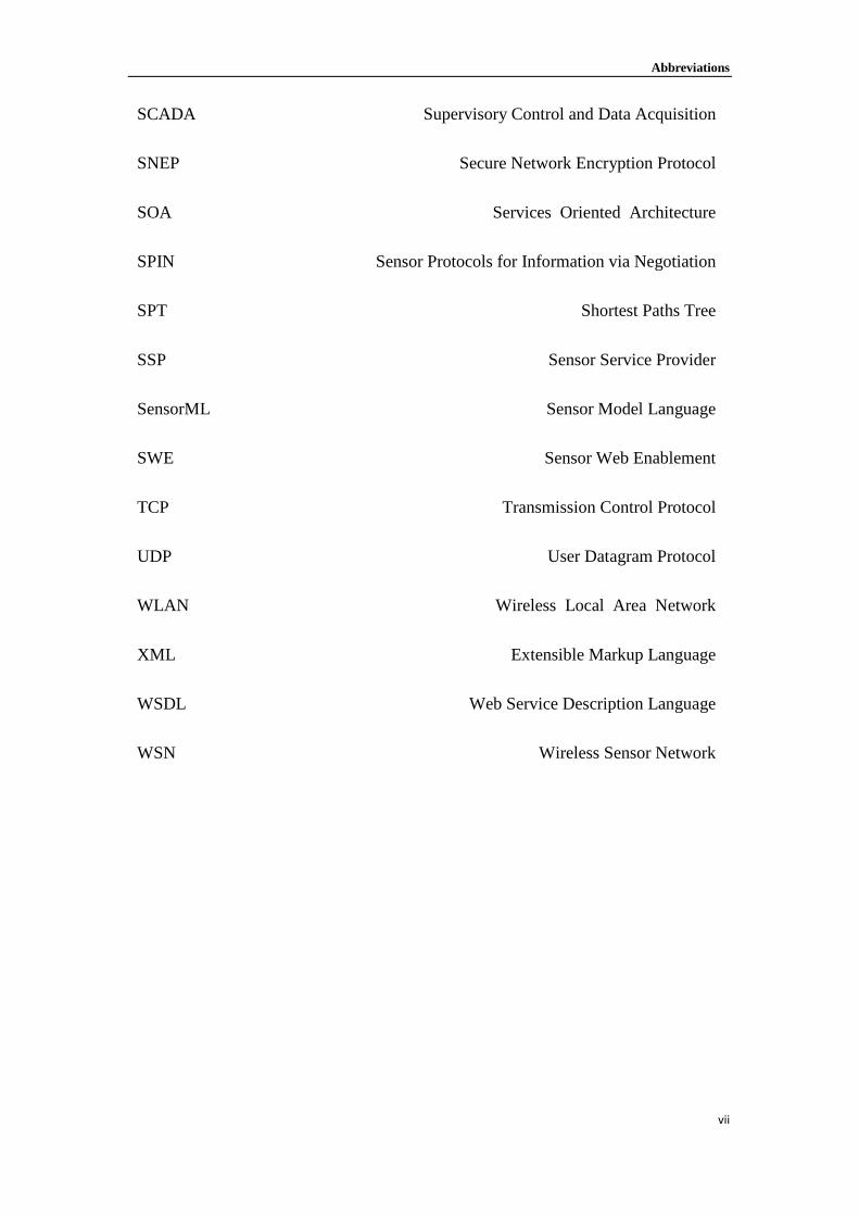
1. Limited power supply. Since the deployment of WSNs is supposed to be random
and requires little or no infrastructure involvement, the power supply for driving
wireless sensor nodes is mainly provided by batteries (Qi et al., 2001). This is a
most important factor that seriously limits the use of WSNs. WSNs are designed
to work in unattended area or, work along over a considerable long period of time
as frequent battery replacement might not easily be achieved.
2. Limited effective range of the wireless communication. A battery normally
powers the transmitter and receiver used by wireless sensor node. Among the
typical components within a wireless sensor node, the radio transmitter consumes
the most energy. Since current technology cannot provide a long-term power
supply without replacing the battery, WSNs use limited transmission power as an
effective way to save energy used on wireless sensor node (Cardei and Wu, 2006).
Consequently, the effective transmission range of the WSN node is restricted.
3. The large number of wireless sensor nodes within WSNs. A wireless sensor
network often consists of a large number of sensor nodes in order to provide an
effective sensor field as required. They can easily cover a relatively wide area.
This characteristic makes it impossible for users to maintain the whole network
manually. A comprehensive management architecture is required to monitor the
WSNs, configure network parameters and implement system updating
(Wagenknecht et al., 2008).
4. Dynamic changes of the network formation. The topology of WSNs may not be
static in the network area. Sensor nodes can easily die and new sensor nodes may
be randomly added to the network. All of these require the sensor network to
have the ability to adjust when the topology of the network is changed
(Bharathidasan and Pomduru, 2003).
5. Management of data flow. In WSNs, each sensor node will generate sensory data
and transfer this data to the specified task manager node for further processing.
As a consequence of the characteristics of wide deployment and limited wireless
communication protocols, strategic management of the distributed data flow,
Chapter 2 Wireless Sensor Networks and Internet of Things
21
query and analysis is important to sensor networks (Elnahrawy, 2003).
In this thesis, we are focused on the challenges of 3, 4 and 5.
Overview of Internet of Things (IoT) 2.2
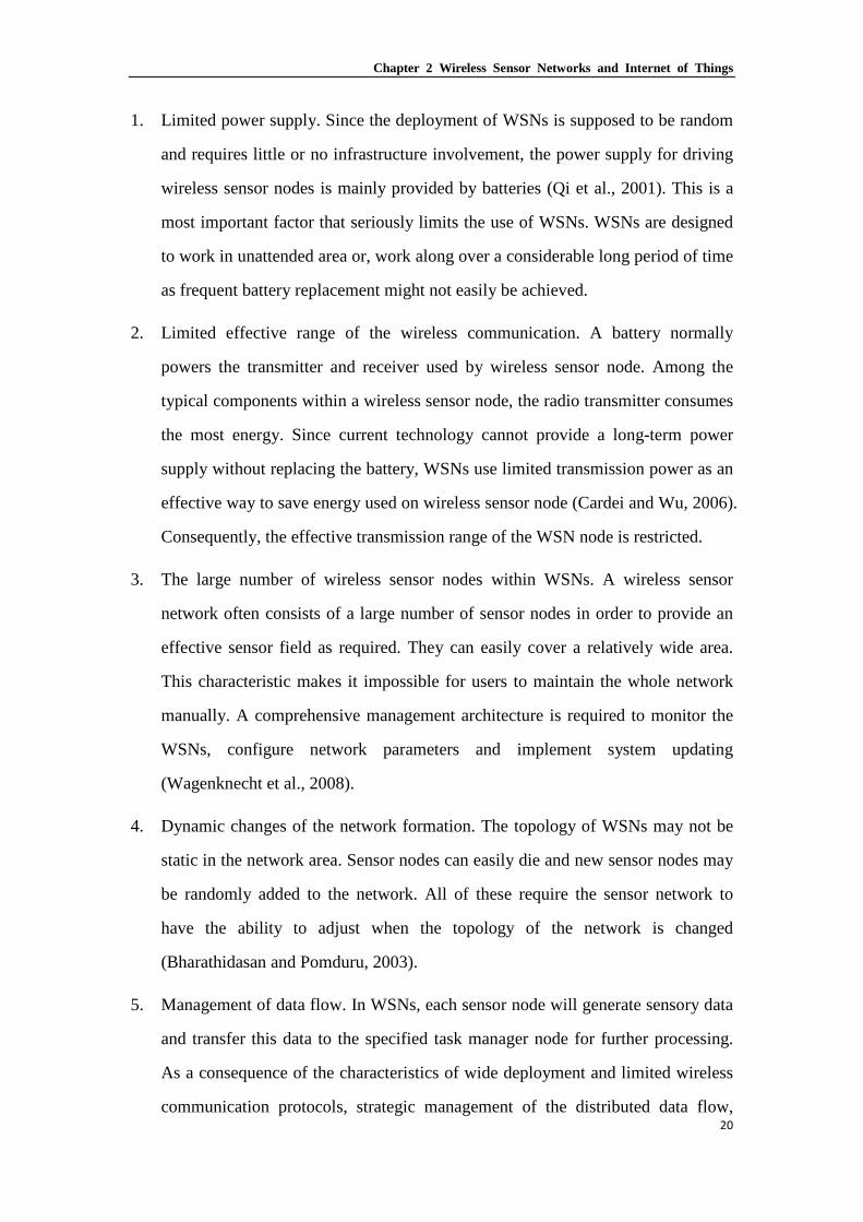
2.2.1 Internet of Things
Developments are rapidly under way to take the wireless sensor network an important
step further. Embedding short-range mobile transceivers into a wide array of
additional gadgets enables new forms of human-gadget communication and
gadget-gadget communication. This adds a new dimension to the world of
Information and Communication Technologies (ICTs); from anytime, anyplace for
anyone, we will now have connectivity with anything (Figure 2-4). The Basic idea of
the IoT is that virtually every physical thing in this world can also become a computer
that is connected to the Internet (ITU, 2005). This definition can be considered as:
“Things do not become computers or powered by computers, but they act as
microcomputers in the Internet”. When they do so, people usually call them smart
things, because they have certain computing resource and can do smarter than normal
things. The IoT is not a new concept, the first announcement of IoT concept was
introduced by Foundation of Auto-ID centre of MIT in 1999. The original definition
for Internet of things is: “A network of Internet-enabled objects, together with web
services that interact with these objects”. Underlying the Internet of Things are
technologies such as RFID (radio frequency identification), sensors, and smartphones
etc. (Gershenfeld, 1999). IoT has gained a recently gained a huge amount of interest
from the general public. The main reason is that the hardware development in the last
decade, like the integrated circuits manufacture process, now makes IoT feasible. The
reduction in size, cost and energy consumption of electronics now allows the
manufacturing of extremely small and inexpensive low-end computers (Payne and
MacDonald, 2004).

Chapter 2 Wireless Sensor Networks and Internet of Things
22
Figure 2-4 A new dimension (ITU, 2005)
The concept of the IoT is mainly driven by continuous progress in microelectronics
and networking technologies in pervasive and ubiquitous computing. It is the
multi-disciplinary study that involves the research in the fields of hardware, near-field
communication, networking, data fusion and software engineering etc. Scientific and
technical challenges require different competencies (Association Institutes Carnot,
2011):
Technology level – challenges linked to the integration of smart ‘network enabled’
objects under strong energy and environment constraints;
Communication and networking level – challenges linked to the massive secure,
dynamic, flexible networking and the ubiquitous service provision;
Intelligence level – challenges linked with the data fusion and service discovery
where data collected by individual smart ‘network enabled’ objects such as RFID
and distributed users enquire wireless sensors.

Chapter 2 Wireless Sensor Networks and Internet of Things
23
Figure 2-5 Three main challenging domains of the IoT
A hierarchy of different levels of technologies involved in the IoT can be identified
from (Figure 2-5). The key functionalities in the technology level, to enable
interaction between the “things”, are identification, sensing, storage, actuating, and
interface. The interface between the real and the digital worlds requires the capacity
for the digital world to sense the real world and to act on it. Technologies such as
RFID, sensors and WSNs are fertilizing some specific functionality to support the IoT.
However, simply equipping objects with microchips and retrieving information at a
local level is insufficient. These smart ‘network enabled’ objects will become
significantly more advanced than current ‘simple’ sensors, RFID or the combination
of these two. They are in particular based on cheap and small wireless devices with
sensing, acting, communication, and advanced signal and information processing
capabilities. IP enabled technologies such as 6LOWPAN (IETF, 2007) make it
possible to build low cost and reliable solutions and services (Dunkels et al., 2004) to
enable the interconnection of various “things” in the IoT.
As a new technology, IoT has to face new challenges in communication and
networking aspects that may be different from the existing Internet. The research
roadmap from the European Commission (European Commission, 2009) deems the
IoT as an integrated part of the future Internet. Some researchers tend to consider the
IoT as a separate part to the Internet. Gershenfeld et al. (Gershenfeld et al., 2004)
describes the IoT as an extension of the Internet to reach out to the physical world of

Chapter 2 Wireless Sensor Networks and Internet of Things
24
things and places that only can feature low-end computers, whilst Fleisch (Fleisch,
2010) argues that the IoT is not on the same level as the Internet, but it is in fact an
application of the Internet like many existing Internet-enabled services. We stand on
Fleisch’s point of view and aim to design and develop a service-oriented architecture
based on the existing Internet for interconnecting the smart ‘network enabled’ objects
contained in the IoT.
Since the concept of IoT was put forward in 2005, we see the deployment of smart
‘network enabled’ objects with communication, sensory and action capabilities for
numerous applications in areas such as health care (Niyato et al., 2009; Oztekinet al.,
2010; Thompson and Hagstrom, 2008), smart buildings (Darianian and Michael,
2008), social networks (Welbourneet al., 2009), environment monitoring (Ilic et al.,
2009), transportation and logistics (Broll et al., 2009) etc. All applications of the IoT
rely on the data collected from distributed smart ‘network enabled’ objects and the
IoT information infrastructure for data transmission.
2.2.2 Design and Integration of objects
The IoT is not the replacement of the Internet as it is not on the same level as the
Internet. It could be considered as an application of the Internet, just like many
existing Internet-enabled services. Following this path, the structure of IoT could have
the similar style as the other Internet applications. In the low level building blocks, the
IoT needs to be addressed in the Internet and linked with other online applications; in
the higher levels, it needs many assorted terminal applications to consume the data.
As a consequence, the IoT may rightly be conceptualized as an extension of the
Internet to reach out to the physical world of things and places that only can feature
low-end computers (Gershenfeld et al, 2004). On the lower levels of IoT application,
the data transmission method is similar to the current Internet, using DNS and TCP/IP.
Additionally, the IoT imposes additional properties on the possible communication
methods such as being wireless and energy efficient. Finally an Internet gateway is
needed, which matches the IoT requirements of low energy consumption, low cost

Chapter 2 Wireless Sensor Networks and Internet of Things
25
and mobility (Samra, 2004).
Identification and addressing progress. There are many existing IoT like projects
based on IP and MAC. These protocols were originally designed for computers,
not microprocessors on the node device. Therefore, energy consumption,
scalability, robustness and computing resources were note important issues. To
avoid these negative factors, a newly developed technology was introduced called
IPv6 over Low Power Wireless Area Networks (6LoWPAN). It is an IPV6 based
Internet protocol that can be implemented with in small-form-factor, low-power
devices with limited processing capabilities. Despite this, it still takes advantage
of the strong AES-128 link-layer security from IEEE 802.15.4. The aim of the
6LoWPAN is not only to improve the compatible between small, smart devices
and usual IP devices, but also to support the IP communication by 802.15.4 link
layer. In an 802.15.4 frame there are only 81 bytes available for higher levels, the
IPV6 header alone occupies 40 bytes. In a case where the UDP were also used, it
will cost an additional 8 bytes of header, so only 33 bytes are left for the
application level. It is clear that a mechanism for header compression is essential
in order to use IPV6 over IEEE 802.15.4 networks. 6LoWPAN defines a
compression mechanism for IPV6 header called Header Compression 1 (HC1); it
is only available if the devices are already part of one 6LoWPAN network so
share the network prefix. After that, there is only the “Hop Limit” field from the
original IPV6 header that must always be present in the packet. So the header can
be elided to two bytes: one used to encode the compression and one for the Hop
Limit field. With the benefits of this, one 802.15.4 device can process the data
much more efficiency with nearby devices. In the future, the 6LoWPAN could
become one of the most popular ways to identify and address the sensors.
Gateway to Internet. Once the sensor devices have been identified and
successfully become “online”, they can be operated and monitored by any
authored application. From a simple application, there is only an Internet
application with pointed IP address that needs to be served like a web based

Chapter 2 Wireless Sensor Networks and Internet of Things
26
monitor system. The gateway works much more like a Domain Name System
(DNS). It translates the target domain name into a corresponding IP address. A
DNS like federated sensor network server was proposed and will be introduced in
chapter 5. In the realistic world, the situation could be more complex; there will
be more than one data consumers and even more smart things need to be joined.
In an ideal open IoT-architecture, not only can every sensor be reached by every
authorized computer or person, but in addition, every person and organization can
set up their own services, link them with identifiers, and offer them to the public
(Fleisch, 2010). For example, a forest fire monitoring application not only
provides the current data to the emergency service station, but the data could also
be shared with other users such as travellers in the area. In addition, when a user
requests the sensor information from that monitoring application, the IoT server
may return some more related information from other application to give more
options.
The application level. The IoT is a large-scale federated network system. All the
applications in it work cooperatively and share the information. All the
applications of IoT should be Internet based services. Newly designed IoT
applications as well as classical web application can join the IoT system. After
joining, they will be reinvented and extended to the real world.
2.2.3 Quality of service (QoS) in IoT enabled network
In the recent years, novel technologies of the Internet continue to emerge. Billions of
Internet accessible devices provide huge amounts of information for the world; they
extend the Internet into most aspects of people’s lives. With the IoT coming, the
Internet is now progressively evolving towards a real-time information platform rather
than the original document sharing network. Nowadays, with the expansion of the
information available on the Internet, Internet Service Providers (ISP) need to
dimension the core network and trunk lines given to the subscriber and need to use
resource reservation control mechanisms rather than the achieved service quality.

Chapter 2 Wireless Sensor Networks and Internet of Things
27
Currently, they still cannot afford the excessive amounts of capacity. So an IoT
optimized efficient Quality of Service (QoS) solution is needed. It is required to be
capable of carrying multiple flows and different services, which have already been
connected to all kinds of equipment from all around the world. With a minimum set of
properties guaranteed by the QoS, such as throughput, maximum delay, jitter and loss
rate, it would allow ISPs to support the IoT services with high quality.
The IoT is a complex and shared system consisting of a plethora of applications,
network equipment and resources. Lots of components are constrained in terms of
computation, communication and energy. The QoS of IoT needs to be across multiple
dimensions. The first dimension is the nature of the stakeholders, which include
applications, resource providers and the network upon which the devices are
connected to. The second is the nature of competing applications in the IoT because
multiple applications must coexist. The last one is the nature of constraints that must
be considered, such as network characteristics, device properties, environment
attributes and application requirements (Fok et al., 2011).
There are several existing QoS solutions that can be adopted in IoT applications.
Network-Sensitive Service Discovery observed the differences between performing
user-side resource selection and provider-side resource selection by integrating
network-sensitivity into the service discovery process. It allows users who are looking
for services to specify both the desired functional and network properties at the same
time. Users’ benefit since they only have to solve a restricted version of the server
selection problem (Huang and Steenkiste, 2004). There is a middleware supporting
multi-dimensional QoS and efficient service selection algorithm that provides the
appropriate ground for QoS-aware composition in dynamic service environments
(Mabrouket al., 2009). It focuses on optimizing the overall QoS provided by a
composition of service endpoints.
In order to respond to network dynamics, the QoS in IoT should be provided by
dynamically adjusted. The application's requirements of an interaction, the

Chapter 2 Wireless Sensor Networks and Internet of Things
28
requirements of resource providers and the nodes must all be considered. A
multi-dimensional QoS will enable expressive and adaptive framework for supporting
multi-hop, opportunistic interactions in the IoT.
2.2.4 Identification, sensing and communication
The Internet of Things is a technological revolution that represents the future of
computing and communications and its development depends on dynamic technical
innovation in a number of important fields, from wireless sensors to nanotechnology.
Figure 2-6 Miniaturization towards the Internet of Things (ITU, 2005)
First, Radio-frequency identification (RFID) is a simple, unobtrusive and
cost-effective system to identify the object and devices to large databases and
networks or the network of networks (the internet). Secondly, by using sensor
technologies, all the collected data contain the physical status of things. Things with
microprocessor embedded can further enhance the power of the network by devolving
processing capabilities to the edges of the network. Finally, miniaturization and
nanotechnology allow smaller devices have intractability and connectivity (Figure
2-6). A combination of all of these developments will build an Internet of Things that
connects the world’s objects in both a sensory and an intelligent manner (ITU, 2005).
RFID technology, which is used to identify physical things with radio waves, is

Chapter 2 Wireless Sensor Networks and Internet of Things
29
considered as one of the key enablers of the Internet of Things. Although it has
sometimes been seen as the successor of bar codes, RFID systems offer much more,
Compared to the other Auto-ID technologies, the RFID system has its own features:
instead of typing or scanning the identification code manually, the RFID systems
typically provide us a non-contact data transfer between the tag and the interrogator
without the need for obstacle-free, line-of-sight reading; tag information can be
rewritable and the tag itself can be recycle and reused; multiple tags can be read
simultaneously by a RFID reader, known as the batch readability of tags, which
makes the identification work much more efficient.
Embedded intelligence in things themselves will distribute processing power to the
edges of the network, offering greater possibilities for data processing and increasing
the resilience of the network (ITU, 2005). There is no definition of how to classify
smart things, but we can consider them as physical items with the ability of
low-weight processing and network connection. Nowadays, they are mainly focusing
on the areas of smart homes, smart vehicles and personal smart things such as the
“Google Glass” and “MYO armband”. In future, more and more things will become
smart enabled, such as smart oven, smart refrigerator, even smart power socket
(Figure 2-7). In such scenarios, the Internet is considered as a carrier of all the smart
objects to provide a fully interactive and responsive network environment.

Chapter 2 Wireless Sensor Networks and Internet of Things
30
Figure 2-7 Smart home for people (ITU, 2005)
2.2.5 Applications of IoT
A huge number of novel applications can be built with the support of IoT; many of
these will improve the quality of our lives. Most of the things around us do not have
communication capabilities. Once these objects are given the ability to communicate
with each other and to process the information received from nearby smart things, a
large scale of applications can be deployed in areas like transportation and logistics,
healthcare, home, office and the wild world. An introduction of these futuristic
applications is given below.
Logistics – With the support of RFID technology, real-time monitoring of the entire
supply chain is possible, even to obtain the product-related information. With this
benefit, logistics enterprises can easily and quickly adjust the supply chain in a
response to changes in the markets. The reaction time of traditional enterprises was
reported to be 120 days from requirements of customers to the supply. However, the
advanced companies like Wal-mart and Metro, which have already deployed some of
the sensors and RFID technology, can do this in just few days and work with zero
safety stock (Yuanet al., 2007).

Chapter 2 Wireless Sensor Networks and Internet of Things
31
Driving assistant – the roads and the rails with sensors and tags will be installed. The
on-vehicle computer can capture the information about this area for better navigation
and safety once a vehicle is in range. For example the speed limitation of the current
road maybe vary but the driver may not notice the road sign, say due to sight being
obstructed by a high vehicle like a lorry. With the interaction traffic system, drivers
may easily obtain the information around their current location. Meanwhile, road-side
devices can receive the data from nearby vehicles and report the live traffic status to
the control station and the other vehicles that are going to pass this road. Enterprises
such as Logistic Companies would be able to locate the delivery vehicle, either to
perform more effective route optimization, which allows energy savings, and also be
provided important information about the delivery time, delays and unexpected
situations. This information can be also combined with the status of the warehouses in
order to adjust the logistic process automatically.
Healthcare – With the benefits of IoT technologies, the healthcare could become much
easier, faster and more efficient with fewer mistakes. With identification on each
patient, it will help reduce incidents such as the wrong drug being used and to provide
a comprehensive medical record. With sensor devices on patients such as WSN based
heterogeneous bio-signal sensors, medics can easily monitoring the patients’
conditions by the health indicators on the patients. It could include different
telemedicine solutions to monitor the patient compliance. The system also can provide
the function of real-time position tracking. It aims to locate the patient during
emergencies such as falling and Disease progression, even to locate and alert the
nearest medics with the status of that patient.
Living environment – A smart living environment can make people’s life easier and
more comfortable. With sensors and actuators installed in the house, the intelligent
system can automatic make adjustments in response to changes in environmental
indicators: to adapted the air conditioning to user’s preferences and the external
weather; to change lighting according to the current level of ambient light; to avoid

Chapter 2 Wireless Sensor Networks and Internet of Things
32
domestic incidents using an intelligent alarm and monitoring system; and to save
money on energy by automatically switching off the unneeded electrical equipment.
In addition, users can get a hybrid viewing of their house and receive a text message
when any unexpected events happen.
Discussion 2.3
This chapter has provided an overview of Internet of Things and Wireless sensor
network. The basic idea of WSNs is to collect environment information by employing
distributed sensor nodes and enable the achievement of “ubiquitous computation”. It
also examines the technologies that will drive the emerging IoT, including 6LoWPAN,
QoS for PAN, radio-frequency identification (RFID), sensor technologies, smart
things, nanotechnology and miniaturization. Also, the detailed developments of RFID
and sensor networks have been investigated, followed by an introduction of
applications by the support of IoT. The technologies mentioned above are the basic
components in further FSN system design.

Chapter 3 Integrating Wireless Sensor Network and the Internet
33
Integrating Wireless Chapter 3.Sensor Network and the Internet
The structure of this chapter is as follows: Section 1 provides a briefly introduces the
motivation for the integration of Wireless Sensor Network (WSN) and the Internet. In
section 2, we review the existing solutions for integrating WSNs and the Internet, and
how they could be integrated as part of Internet. Section 3 analyses the infrastructural
issues in general. Section 4 introduces the major challenges that may hinder this
integration process, showing both the sensor network issues and the
integration-specific issues. Finally, Section 5 concludes this chapter.
Introduction 3.1
In the upcoming Internet of Things (IoT), the everyday objects are all potential actors
of the Internet, objects that can produce and consume information. As we have
previously mentioned, the elements of the IoT will include not only devices that are
currently connected to the internet, such as computers and smart phones, but also
include items such as clothes, food and even living beings. If a computer system
needs to obtain data from a certain environment, one of the tools may be used in
wireless sensor networks. WSNs have great potential for many applications that we

Chapter 3 Integrating Wireless Sensor Network and the Internet
34
introduced in the previous chapter. As WSNs become more numerous and their data
more valuable, it becomes increasingly important to have some common means to
share data over the Internet (Reddy et al., 2007). Since WSNs can be easily organized
into different environments to monitor or track target objects for knowledge discovery
or information collection, they are an essential infrastructure for ubiquitous computer
systems (Zheng et al., 2007). Additionally, WSNs have also been considered in
Ambient Networks (Niebert et al., 2004). For all these reasons, integrating WSNs
with the Internet has become increasingly desirable and necessary.
Existing solutions for Integrating WSN and the 3.2
Internet
Most of the existing proposed solutions that combining the WSN and the Internet aim
at integrating the networks through the mapping of protocol stacks and logical address
formats used in both networks.
The sensor network is like a living body that needs a brain to react to the information
coming from the physical world. That means it needs to interact with an external
system in order to be useful. The simplest sensor network deployment consists of a
group of sensor nodes and a base station. A computer system or a human being will
collect the data from the base station. It will make use of the information coming from
the sensor nodes. For example, the manager will inspect the location of targets using
the collected data from the base station.
In order to improve the accessibility and usability of the services, the services should
be easily accessible from external networks. Communication to the sensor nodes
either via the base station or a direct connection is needed to enable the flow of
information generated by the sensor network to be accessed and analysed by different
applications controlled by aboard users. The sensor network can be operated and
controlled remotely, without physically accessing deployment field. This will improve

Chapter 3 Integrating Wireless Sensor Network and the Internet
35
the sharing of information and realize the real Internet of things. Recent research in
the field of wireless sensor network include SensorWeb (Liang and Tao, 2005),
Wireless Sensor and Actor Network (Akyildiz and Kasmoglu, 2004), ocean sensor
network (Akyildiz, Pompili and Melodia, 2004), ZigBee technologies (Akyildiz,
Pompili and Melodia, 2004) for low power communication, memory management
mechanisms, various routing technologies, and other problems in the Ad-Hoc
networking. However, the data obtained from local wireless sensor networks are
forwarded and processed in the server systems (sink node or base station), then passed
to the client via the Web application uses an intermediary (such as SQL). Therefore, in
the future ubiquitous and user environment, sensor nodes in WSNs should have a
standard identifier and have direct access to attribute information of specific sensor
nodes in order to enable use from unique URI in Web services.
Figure 3-1 Classification of integrated approaches
For these purposes, the researches in the wireless sensor networks has mainly focused
on routing protocol, MAC protocol, location tracking, and Internet applications that
process and use the sensor data for future ubiquitous computing. The studies (Dunkels,
2004; Dai, 2004), which are related to Internetworking between the WSNs and the
Interagted Approaches
Front-End Proxy Solution
Gateway Solution
Application-level gateway
Delay-Tolerant Networking based Gateway
Service-oriented Gateway
TCP/IP Overlay Solution
IP Overlay Network
Overlay sensor Network

Chapter 3 Integrating Wireless Sensor Network and the Internet
36
Internet, have been done by lots of research groups. According to the literatures
(Roman and Lopez, 2004; Kim, et al., 2008; Kosanovic and Stojcev, 2011), these
works can be divided into three fields (see Figure 3-1). One is front-end proxy
solution, which performs the connection by a middleware proxy and there is no direct
connection between WSN and the Internet. The second is a gateway solution that is
deployed by a gateway located between the wireless sensor networks and the Internet.
The final field is TCP/IP overlay solution that is performed by an overlay network
constructed on either the wireless sensor networks or the Internet.
3.2.1 Front-End Proxy Solution
In the Front-End Proxy solution, the external Internet hosts and the sensor nodes
never communicate with each other directly. The simile can be applied to this solution:
the base station likes a supermarket between the farm and the customers. It acts as an
interface between the data acquisition network (sensor network) and the data
dissemination network (the Internet). In Figure 3-2, we can see the base station collect
and store all the information from the sensor nodes. There is no direct connection
between the Internet and the sensor nodes: the base station will process all the
incoming and outgoing information.
Figure 3-2 Front-end Proxy solution
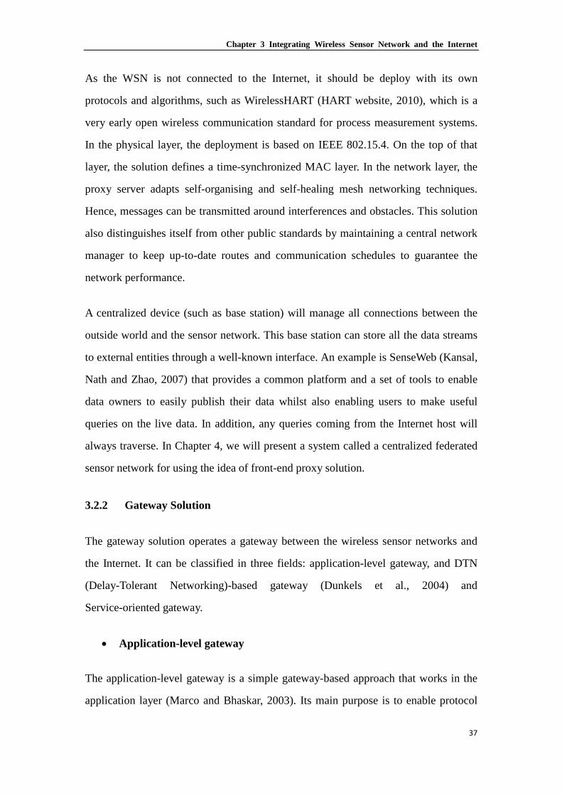
Chapter 3 Integrating Wireless Sensor Network and the Internet
37
As the WSN is not connected to the Internet, it should be deploy with its own
protocols and algorithms, such as WirelessHART (HART website, 2010), which is a
very early open wireless communication standard for process measurement systems.
In the physical layer, the deployment is based on IEEE 802.15.4. On the top of that
layer, the solution defines a time-synchronized MAC layer. In the network layer, the
proxy server adapts self-organising and self-healing mesh networking techniques.
Hence, messages can be transmitted around interferences and obstacles. This solution
also distinguishes itself from other public standards by maintaining a central network
manager to keep up-to-date routes and communication schedules to guarantee the
network performance.
A centralized device (such as base station) will manage all connections between the
outside world and the sensor network. This base station can store all the data streams
to external entities through a well-known interface. An example is SenseWeb (Kansal,
Nath and Zhao, 2007) that provides a common platform and a set of tools to enable
data owners to easily publish their data whilst also enabling users to make useful
queries on the live data. In addition, any queries coming from the Internet host will
always traverse. In Chapter 4, we will present a system called a centralized federated
sensor network for using the idea of front-end proxy solution.
3.2.2 Gateway Solution
The gateway solution operates a gateway between the wireless sensor networks and
the Internet. It can be classified in three fields: application-level gateway, and DTN
(Delay-Tolerant Networking)-based gateway (Dunkels et al., 2004) and
Service-oriented gateway.
• Application-level gateway
The application-level gateway is a simple gateway-based approach that works in the
application layer (Marco and Bhaskar, 2003). Its main purpose is to enable protocol

Chapter 3 Integrating Wireless Sensor Network and the Internet
38
transformation. This method is easy to implement, has low deployment cost, and
allows the Internet to work efficiently on heterogeneous networks because isolated
operation between the WSNs and Internet is possible (Zuniga and Krishamachari,
2003). In Figure 3-3, we can see the base station acts as an application layer gateway
in charge of translating the lower layer protocols from both networks. As a result, the
information can be directly exchanged between sensor nodes and the Internet hosts. In
this approach, the WSN still has some infrastructural independence; a translation table
is required to map the WSN address to IP addresses. Some web service solutions such
as TinyREST (Luckenbach et al., 2005) take advantages of this approach.
Figure 3-3 Application-level gateway solution
• Delay-Tolerant Networking based gateway
The Delay-Tolerant Networking (DTN) is defined as a network constructed with
regional networks. Here, region implies a network that employs same technology. So,
the DTN-based gateway internetworks between the regional networks that employ the
same technology using application-level gateway. This method controls the delay time,
transforms the protocol efficiently and provides the interoperability between the
regional networks. Figure 3-4 shows that the DTN-based gateway supports massage
exchanges between different networks via a bundle layer (Fall, 2003). The base
station is able to store and forward packets between the networks. In this case, if the

Chapter 3 Integrating Wireless Sensor Network and the Internet
39
link between the base station and the sensor node is broken, the packet is not
transmitted and is stored for future forwarding (Kosanovic and Stojcev, 2007).
Figure 3-4 DTN gateway solution
In the DTN architecture, the communication in it is facing unpredictable delays and
potentially high bit-error rates. The interconnection mechanism between the Internet
and WSN is provided by overlaying the DTN on the top of the Internet. A DTN
gateway node is located between those two networks and provides general
mechanisms and interface for a large number of queries.
• Service-oriented gateway
Service-oriented gateway is to separate the complicated query management between
WSN and the Internet from the gateway. It can provide a quick user response. There
are some service-oriented solutions that enable the integration of Internet and WSNs.
A reflective- and service- oriented middleware for WSN is proposed in (Shi, 2005),
where three roles (Application Agent, Register Agent and Resource Manager) are
defined in the service-oriented model architecture. In (Priyantha, 2008), the service is
implemented directly on a single sensor node and the sensor node is considered as
(web) service providers. They consider the WSN as a service provider rather than a
service consumer. Their model aims to provide an interoperate mechanism between

Chapter 3 Integrating Wireless Sensor Network and the Internet
40
the services from both networks, which is supplied by a sensor node from WSN or by
a host from the Internet. The process is in a uniform and transparent irrespective of
the client or the service location. In Chapter 5, our research (distributed federated
sensor network) is focused on the service-oriented gateway solution.
3.2.3 TCP/IP Overlay Solution
From the previous solutions, we can see there some drawbacks. For example, all the
communications around the WSN may be suspended if the gateway or proxy fails.
The previous proxy solution and the gateway solution need to be equipped with a
stable storage component to save the sensor data and a component with powerful
processing capability to process the sensor data and manage queries. By doing this, it
may make the gateway physically larger than the sensor nodes, reducing its life-time
and increasing the difficulty of designing an integrated architecture. This is because
the sensor data is logically far away from the users in the Internet.
In the TCP/IP overlay Solution, sensor nodes communicate with other nodes by using
TCP/IP or a similar protocol. Therefore, the base station behaves as a router in the
Ethernet that forwards the packets between the sensor nodes. We classified two fields
in this approach: IP overlay network and overlay sensor networks.
• IP overlay network
The first approach points out that it is possible to an implement TCP/IP protocol stack
on a microcomputer system with very poor resources, 8-bit microprocessor with only
2kB RAM memory has been demonstrated (Dunkels, 2005). This was (Dunkels, 2004)
based on a overlaying-based integration structure that can send and receive the data
via IP packets after implementing the IP protocol and assigning the IP address to the
sensor nodes on wireless sensor networks (see Figure 3-5). Therefore, this method has
two hot issues. Firstly, how is the IP address assigned to the sensor node? Secondly,
how to mix the address-based and data-based routing efficiently according to network

Chapter 3 Integrating Wireless Sensor Network and the Internet
41
traffic? Recently, using the location of the sensor node was introduced in IP address
assignment and the Directed Diffusion and ACQUIRE were proposed in routing
protocol to address these two important issues.
Figure 3-5 IP overlay network solution
One example is 6LoWPAN, which provides a transmission method for the IPv6
packet over LoWPAN. Its routing mechanism is limited by the available cyclic sleep,
low overhead, small size routing table, and extended by inserting the IP and TCP/UDP
environments over MAC/PHY layer. As a result, 6LoWPAN reuses verified legacy
technologies, interchange of the information and collaboration to non-IEFT
Corporation like ZigBee Alliance. Currently, 6LoWPAN uses verified and
well-known IP technologies, has an outlook that can use the legacy network
infrastructure to avoid additional cost, but cannot adopt IPv6 on ZigBee because it
requires more memory (64K), incurs high costs, and is difficult to implement (IETF
website, 2013). In chapter 6, we will improve the 6LoWPAN solution and implement
it in an iNet tracking and localisation system.
• Overlay sensor network
In contrast, an overlay sensor networks (Dai and Han, 2004) is an overlaying-based
integration. It combines the sensor networks with the Internet and extends the data
centric routing on the sensor networks to the application-level overlay sensor

Chapter 3 Integrating Wireless Sensor Network and the Internet
42
networks on the Internet. In the meantime, all the data collected from the sensor
networks is forwarded to the host on the Internet once the payload of the IP packet is
encapsulated on the gateway. This approach is easy to implement and interconnect via
programs on the host as the sensor data has been combined with an Internet protocol
message. The major components include the virtual nodes running over the Internet
and the overlay gateway (see Figure 3-6). A virtual node is defined as any entity that
communicates with peer entities on a real sensor network through a common set of
protocols, network layer and above. The sensor overlay permits a rich and versatile
environment for the interconnection of virtual nodes, which collectively from a virtual
sensor network. The virtual sensor node also can interpret WSN packets since it has
installed the WSN protocol stack in addition to TCP/IP stack.
Figure 3-6 Overlay sensor network solution
This approach can be identified as: header overhead, high bit error rates, high energy
consumption for end-to-end multi-hop retransmission, differences in routing protocols
and implement of addressing and routing schemes (Lei et al., 2006).
Currently, it is widely assumed that future deployments should be based on IPv6
(Domingues et al., 2007). However, there are solutions using both IPv4 (Braun et al.,
2003) and IPv6 (Montenegro et al., 2007) for sensor nodes. Even more forward
looking, people are doing research on motes to give them the ability of providing web

Chapter 3 Integrating Wireless Sensor Network and the Internet
43
services by reporting its interface using the Web Service Description Language
(WSDL) and connecting to other hosts using HTTP (Priyantha et al., 2008).
Infrastructural issues for integrated approach 3.3
The advantages of integrating WSN with the Internet are obvious, but there is no
exact answer to whether sensor nodes should be completely integrated inside the
Internet or should be maintained independency as part of a cloud of “adjacent”
networks. Different solutions are suitable for the requirements of specify applications.
There are some infrastructural issues that have to be considered when deploying
WSNs that are connected to the Internet:
• Access Point
To have multiple WSNs connected to the Internet, an access point should have
multiple wireless/wired interfaces. The wireless interface could be a multiple access
wireless technology such as the IEEE 802.11. Throughout the experimental phase of
our research, several wired interfaces were used, i.e., Ethernet and variable-speed
serial connections.
• Application
Users on the Internet run applications that query the WSNs. Applications on the
Internet receive the collected data from WSNs for analysis and intelligence gathering.
In the literature (Su, 2008), the term sensor-application is used to describe those
applications running on the Internet to serve WSNs. They are located on different
hosts and each host could have more than one sensor-application; there can be an
infinite number of sensor-applications on the Internet and there is no previous
knowledge of the available WSNs initially. In this scenario, once a sensor-application
first starts up, it sends a registration request to a registration service manager model
and obtains a list of valid WSN candidates.

Chapter 3 Integrating Wireless Sensor Network and the Internet
44
A sensor-application may maintain a certain priority level to describe the importance
of the application. The priority information is used to provide appropriate quality of
service (QoS) for sensor-applications.
• Addressing
In the front-end proxy solution, it is necessary to provide functionality in the base
station interface (e.g. as a web service) to send a message to a specific sensor node.
This is not the case of the other solutions, where a sensor node is allocated with a
specific IP addresses. But, it is not clear how IP addresses can be used in sensor
networks. The identification of a single node can either use location information or
data-centric protocols.
• Protocol
It is possible to integrate a sensor network inside the Internet by achieving
interoperability at the network and application layers using TCP/IP or web services
respectively. In addition, a unified standard protocol is also beneficial for achieving
interoperability between different service providers. On the other hand, it is necessary
to use specific protocols to meet the requirements of some special applications in the
scenarios where the WSN is deployed; they must react adequately and optimally to
application-specific problems.
• Data Availability
When a sensor node is offline, it cannot provide any service, such as real time data
streams from its sensors or report the data over critical value. However, if it is located
in a proxy or a gateway, there can be specific network mechanisms that allow the
provisioning of data regardless of the state of the node (e.g. by measuring data from
nodes that are in the same context rather than the broken node).
• Network-specify issues

Chapter 3 Integrating Wireless Sensor Network and the Internet
45
A WSN always has specific features because of their sensing purpose that are
different from other network paradigms. In general, its nodes are battery-powered; in
order to save energy to extend the life cycle, the data rate of the wireless channel is
very low (i.e. 250kbps in the IEEE 802.15.4 standard). Therefore, both the WSN
protocols and the applications that use its services should take this into account.
Challenges for integrating WSN and the Internet 3.4
The previous section described the infrastructural issues for integration, which
involves assigning additional responsibilities to sensor nodes in addition to their usual
sensing functionality. To highlight and discuss the challenges emerging from such
novel responsibility assignment, we selected three main potential tasks that the sensor
nodes would have to accomplish: security, Quality of Service (QoS) management, and
network configuration.
• Security
Security is one of the important challenges for opening WSNs to the Internet. The
current identified attack requires a physical structure close to the target WSN to
capture or to deploy malicious nodes. Integrating WSNs with the Internet will mean
the location does not limit the attack any more. Attackers may threaten WSNs from
anywhere on the Internet. In addition to this location diversity, there may be some
new threats, like malware, introduced by the Internet connection. The most current
WSNs are protected by a central or unique gateway for protection against Internet
threats. Because of the characteristics of WSNs, the existing security mechanisms
cannot be reused directly because of the limited energy, memory and computational
ability of the sensor nodes. For example, common Mica2 motes offer 7.3 MHz 8-bit
micro-controllers with 128 Kbytes of reprogrammable flash memory, 4 Kbytes of
RAM and 4 Kbytes of EEPROM. In current research, many services on the Internet
make use of cryptography with large key lengths such as RSA-1024. This is not

Chapter 3 Integrating Wireless Sensor Network and the Internet
46
suitable for sensor nodes in WSNs. Consequently, the new security mechanisms are
required to protect WSNs from attacks over the Internet.
• Quality of Service
Sensor nodes are expected to contribute to QoS management by optimizing resource
utilization for different devices on the WSNs as a part of IoT. Due to differences in
the devices, we have considered new perspectives for the workload distribution. In
fact, resource heterogeneity may be deployed to share the current workload between
nodes that offer the active resources. In order to improve the QoS, collaborative work
is required to support different functionality, such as security mechanisms. However,
the existing techniques for QoS in the Internet may not be suitable for WSNs. For
example, any sudden changes may require a significant reconfiguration for WSNs in
the connection. Hence, the novel approaches must focus on ensuring delay and loss
guarantees.
• Configuration
In addition to security and QoS management, sensor nodes are able to provide help
for WSN configuration, which includes transferring different protocol and supporting
different tasks, such as address administration to ensure the network constructions and
ensuring self-organising or self-configuration capabilities for WSNs. Self-organising
participating nodes is not a common feature in the Internet but is one of important
characteristics in WSNs. In our research, we will focus on the challenge of realising
the unattended operation of autonomous sensor nodes for different applications on the
Internet.
Discussion 3.5
In this chapter, we discussed how to integrate WSNs into the IoT by dividing the
existing approaches in three fields: front-end proxy solution, gateway solution and
TCP/IP solution. All three solutions each have their own unique strengths and features

Chapter 3 Integrating Wireless Sensor Network and the Internet
47
and are suitable for different types of applications. For example, the front-end proxy
solution is more suitable for centralised management, where the system functionality
will be restricted by central device failures. The gateway solution and TCP/IP solution
are more like a distributed system, or even a mixed system, so they are resilient to
single device failures. In front-end proxy solution, the system can store and forward
the valuable data when a node is not available. The gateway solution can improve the
redundancy of the network by having multiple gateways. The nodes in TCP/IP
solution are Internet accessible, so they are not affected by the failure of any single
point. However, TCP/IP is the weakest structure of these three solutions because they
are most vulnerable to attack from external networks. We introduced the
infrastructural issues for the integrated approach, which involved assigning and
discussing the challenges emerging from novel responsibility assignment, namely
security and QoS management, and network configuration. We will design and
configure different improved architectures for these three solutions and implement
them in different applications in the following chapters.

Chapter 4 Centralized Federated Sensor Network - Front-End Proxy Solution
48
Centralized Federated Chapter 4.Sensor Network - Front-End Proxy Solution
As described in previous Chapters, our investigation of the integration of various
WSNs starts from the bottom of the requirements hierarchy, which is the centralized
federated sensor network system. In this chapter we will discuss the possible
implementation of integrating different WSNs, which will lead to the architectures for
the centralized federated sensor network. After that, we will present the five
components of the system. They are Sensor networks, Sensor Proxy, Virtual
coordinator, Data processor and Application. This is followed by the details of the
components, the reactions and the combinations. The system demonstration is PC
based, instead of self-developed PCB hardware, and the Jennic 5139 development kit
is chose for the WSN component.
Background and motivation 4.1
With the popularity of wireless sensor network (WSN), several applications have been
developed by civilian and business as well as by military users (Ren, et al. 2003).
Each WSN is independent from all others so the data collected by one can only be
analysed and used by a single application. This feature limits the availability and

Chapter 4 Centralized Federated Sensor Network - Front-End Proxy Solution
49
usability of such sensor data. In addition, sensor data is often meaningless unless it is
associated with other data such as time, such as an absolute position. Unfortunately,
previous designs do not considered situations where several WSNs work together.
Therefore, a system that combines multiple sensor networks for collaborative working
is required. We call such collaboration a Federated Sensor Network (FSN).
4.1.1 Federated Sensor Networks
A federated sensor network might contains a hundred thousand sensor nodes running
different applications in parallel, such as a city wide collaborative sensor network that
consist of a huge number of sensor nodes with a variety of sensor devices
(magnetometers, temperature, pollution, air pressure, cameras), providing input into a
large spectrum of diverse applications. A reliable quality of service should be
provided to allocate bandwidth and computation resource.
A. Uniting vastly different devices and services
Despite great variety in the type of data gathered and complexity of nodes within a
FSN, the multiple sensor networks within it must act as if it was a single system.
However, the inter-changeability of nodes might be limited because the intermediate
network nodes, responsible for processing and relaying data between sensors and
applications, may also be heterogeneous. For instance, a medical monitoring scenario
may be tied together with multiple wireless sensor, DPAs, laptops, a necessarily
reliable, secure routing network, and legacy hospital systems (Ledlie et al., 2004).
This diversity presents problems of interfaces. There are several research focused on
naming, lookup and interfaces has come from Smart Grid (Foster et al., 2002) and
ubiquitous computing (Arnstein et al., 2002) research. Existing protocols that require
point-to-point communication, significant translation processing and large payloads
may prove heavyweight data transmission (Ledlie et al., 2004) because applications
will need to reach the base station.
B. Functioning continuously despite intermittent connectivity

Chapter 4 Centralized Federated Sensor Network - Front-End Proxy Solution
50
A data gathering network should be robust against intermittent connectivity. Network
devices and services should be able to disconnect and reconnect seamlessly. By
considering partitions within the network and planning for disconnection scenarios,
the network infrastructure can be optimized for these situations.
C. Placement of in-network services constrained by Device and Network
Data gathered by a sensor is transmitted through a network to some application. This
process can be improved by including some in-network processing, however placing
operators and optimizing a system while adhering to device constraints (e.g. efficiency,
access control rights, etc.) poses a challenge.
D. System-wide security
Many of the motivating applications have stringent security requirements like
authentication, access control and encryption. A unified threat model must be
established along with a full analysis of weak points within the network. Many new
attack points may develop where separate sensor networks connect to a larger network.
A general approach is not viable; each application must be considered in its entirety
for a realistic security solution.
E. Power to draw inferences both within and between sensor networks
A powerful tool that could be made available through the use of multiple sensor
networks is the ability for separate sensor networks to cross-correlate data. This
would help in preventing false positives by combining information gathered from
similar networks where sensor sensitivity differs in orders of magnitude
4.1.2 Existing Solutions
The application scenarios of data collection networks rely on sensor networks,
middleware, distributed query processing, and the work of many other self-contained
research disciplines. The following are the related work in these areas.

Chapter 4 Centralized Federated Sensor Network - Front-End Proxy Solution
51
Figure 4-1 Example of an Hourglass system (Shneidman et al., 2004)
Hourglass
Hourglass (Shneidman et al., 2004) is an internet-based data collection network for
connecting multiple heterogeneous sensor networks together with services and
applications in a robust fashion. An example of an Hourglass system is given in
Figure 4-1. Data flow in Hourglass is based on “circuit", it is a data path through the
system to ensure that an application receives the data in which it is interested. A
circuit includes intermediate services that perform operations on the data. Services are
organized into distinct service providers that capture a single administrative domain.
Each service provider includes a circuit manger, which is responsible for the set-up
and management of circuits, and a registry, which aids service discovery. Hourglass
services have well-specified interfaces that are used to communicate with other
services, the circuit manager, and the registry for circuit establishment, data routing,
circuit disconnection, and service discovery. An existing entity can join an Hourglass
system by implementing the core functionality required by these interfaces. Sensor
networks and applications may join the Hourglass system through proxy services in
order to avoid the cost of running an Hourglass service natively.
SenseWeb
Some of the existing solutions use a data bridge in the WSNs to collect and transmit

Chapter 4 Centralized Federated Sensor Network - Front-End Proxy Solution
52
sensor data. An example is the SenseWeb (Santanche et al., 2005) from Microsoft
Research, which aims to provide a common platform and a set of tools to enable data
owners to easily publish their data while also enabling users to make useful queries on
the live data. The SenseWeb platform transparently provides mechanisms to archive
and index data, to process queries, to aggregate and present results on geo-centric web
interfaces such as MSN Virtual Earth, etc. SenseWeb will collect data from sensors
(which could be cameras, thermometers, theatre booking computers etc.). These
devices may be either placed permanently at some locations or could be individually
consumer devices. The data (images and information) will be pushed to a central
database for indexing and making it searchable. Then, the online mapping system
could provide particular pieces of information, from which a user could pick and
choose the location.
Figure 4-2 SenseWeb Architecture (Santanche et al., 2005)
SenseWeb is facing to general Microsoft LIVE users, and using Microsoft Bing MAP
as a sensor data searching result presenter. Its deficiencies include the lack of
provision of any remote control mechanism. Therefore, users can only access sensor
data from the SenseWeb service, which means there is more limitation on that service.
Semantic Sensor Web
The SSW is a framework for providing enhanced meaning for sensor observations so

Chapter 4 Centralized Federated Sensor Network - Front-End Proxy Solution
53
as to enable situation awareness. It enhances meaning by adding semantic annotations
to existing standard sensor languages of the Sensor Web Enablement (SWE). This was
developed by OGC and aims to solve the problems about lack of standardization for
sensor data. These annotations provide more meaningful descriptions and enhanced
access to sensor data than SWE alone, and they act as a linking mechanism to bridge
the gap between the primarily syntactic XML-based metadata standards of SWE and
the Resource Description Framework (RDF) or Web Ontology Language (OWL) –
based metadata standards of the Semantic Web. In association with semantic
annotation, ontologies and rules play an important role in SSW for interoperability,
analysis, and reasoning over heterogeneous multimodal sensor data (Shethet al., 2008).
An ontology is a formal representation of a domain, composed of concepts and named
relationships. On a broad level, we can classify ontologies along the three types of
semantics associated with sensor data — spatial, temporal, and thematic — in
addition to ontological models representing the sensor domain. The SSW envisions a
registry of domain-specific ontologies, which is similar to the Open Biomedical
Ontologies at the National Centre for Biomedical Ontologies (www.bioontology.org).
Figure 4-3 shows a subset of concepts and their relations from a suite of ontologies in
SSW, modelling the weather domain.
Figure 4-3 Concepts and relations in Semantic Sensor Web (Shethet al., 2008)

Chapter 4 Centralized Federated Sensor Network - Front-End Proxy Solution
54
Centralized Federated Sensor Network 4.2
‘Centralized’ is one of the common architectures in network topology. It is a type of
network where all the components connect to a central server, which is the acting
agent for all communications. The centralized server must store all the components’
account information. This kind of structure is popular in the instant messaging
platform area. It is also named Centralized Server Structure. As described in the
previous review chapter, the approaches for integrating the WSN and the Internet can
be divided into three types, which are: Front-End Proxy Solution, Gateway Solution
and TCP/IP Overlay Solution. In a Front-End Proxy solution, there is a base station
serves as an interface between the sensor networks and the Internet. The base station
collects and stores all the information coming from the sensor networks, and sends
back the control command to the sensor nodes. There is no direct connection between
the Internet and a sensor network, which means all the incoming and outgoing data
will be parsed by the base station. As the sensor network is completely independent
from the Internet, it keeps all the existing protocols and algorithms.
In this chapter, we will present a FSN, which is the combination with Centralized
Server Structure, named centralized federated sensor network. The idea is from the
Front-End Proxy solution of the integration for WSN and the Internet. From the IoT
concept, a centralized federated sensor network can be considered as part of the IoT
architecture. A centralized network is more suitable for small scale network
deployment, which can later join the future IoT system as a component.
System Description 4.3
A federated sensor network is a unified system to collect, share, process and query
sensor data from authorized sharing sensor networks. It aims to provide an
architecture which common sensor networks can easily join and share the sensor data
without requiring any modification to the existing sensor network, just like “plug and

Chapter 4 Centralized Federated Sensor Network - Front-End Proxy Solution
55
play”. It is based on the Independent network, which is the first approach of
connecting WSNs to the Internet described in Chapter 3. It involves connecting both
the independent WSN and the Internet through a single proxy server. According to
this approach, this system can be cheap to deploy and easy to maintain as there is only
one path connected to the outside network. In this system, all the sensor networks
connect to the upper layer by one attached Data Node device, which acts as a sink
node in the WSN. Introducing this component allows the system to have better
compatibility to different kinds of sensor networks. The system has a layered
architecture as shown in Figure 4-4. The components can be divided into five parts:
Sensor Networks
All types of sensor network will be accepted including wireless sensor network and
static wired sensor network. There will be a data processing component called the
Data Node to enable the existing sensor networks to export sensor data and provide
communication with the upper layer (Sensor Proxy). The Data Node is a device
attached to a WSN, which collects sensor data and forwards it to the server or the
backup database. The data collection node is designed to be compatible with common
WSNs, such as the ZigBee stack and the IEEE802.15.4 stack, and can be switched by
the embedded software. To get the compatibility with different types of WSNs, the RF
module of the Data Node must be able to handle both wireless transmission standards;
a good example is the XBee/XBee Pro from MaxStream, Inc.. In addition, the existing
sensor network can joins the system automatically without any modification needed
from the benefit of Data Node.

Chapter 4 Centralized Federated Sensor Network - Front-End Proxy Solution
56
Figure 4-4 System architecture of centralized Federated Sensor Network (Xu and
Yang, 2009)
Sensor Proxy
The sensing data are provided by many kinds of the sensor network that can measure
various environment variables. They may be static if installed in buildings and road
side, or be mobile, if carried by humans or vehicles. Sensor networks may be based on
many different platforms with different interfaces for accessing. Low powered
wireless sensor nodes may communicate via the IEEE 802.15.4/ZigBee standard.
Some sensor networks may have standard power supplies to obtain higher bandwidth,
reliability and life cycles, even their interfaces may be variable. To solve the problem

Chapter 4 Centralized Federated Sensor Network - Front-End Proxy Solution
57
of network complexity, the Sensor Proxy has been introduced. It provides a universal
interface to all types of sensor networks and implements specific methods to
communicate with each sensor network. The upper layer components access the
Proxy for sensor data, data transmission query and sensor network operation by using
a specific API. As a proxy server of sensor network, the only way to connect to the
inside network is to go through it. Therefore, all the under sensor network layer traffic
must reach the upper layer (Virtual Coordinator) before returning. This is good for
monitoring the system processes to avoid any unauthorized access.
Virtual Coordinator
The Virtual Coordinator is the central access point for all applications and sensors in
the system. A sensor network connects to the Virtual Coordinator to register its own
feature for further indexing by users. The sensor data will be fed to the applications
that have stored their interests. Users are able to login to the system and pick up their
desired sensor data. There are three modules included in the Virtual Coordinator: User
Manager, Sensor Manager, and Application Manager.
1) The application manager serves as a middle data access layer between sensors
(Sensor Proxy) and the upper layer (applications). It manages applications that
are going to be, or already are, data consumers in the system. When a new
application wishes to join the system and sends a query to the application
manager, it records useful details like type, IP, location, register time and data
interesting. It also provides a searching scheme to locate the application that has
resisted interest once the sensor network detects something and sends an alert. In
the meantime, users are able to create a profile of the sensor data they are
interested in and set critical value so that the system will notice them when their
interested data is captured.
2) The user manager implements user authentication mechanisms. For security, the
system only allows registered users to access the sensor data. The user needs to
authenticate by providing a user name and password. Then the user manager will

Chapter 4 Centralized Federated Sensor Network - Front-End Proxy Solution
58
generate a unique identify code that will expire after a certain period of time for
the encryption module.
3) The sensor manager provides an index service for all available sensors and their
characteristics. It works similar to a Domain Name Server (DNS) on the Internet,
translating informal sensor descriptions, such as sensor types, location and logic
names, into physical sensor identifiers and provides an index for the upper layers.
Furthermore, it provides a service operation for registering new sensor networks.
In addition, it provides a means of modifying the characteristics of registered
sensor networks as well as methods for the removal of previously registered
sensor networks.
Data processor
Data Processor is the part to enhance the federated Sensor Network and is the
component that deals with the sensor data directly. It contains three modules:
1) A classifier is an enhanced part of the Application Manager. The classifier
classifies the sensor type by using the indexing service of the Sensor Manger when a
new sensor network joins; it stores the related sensor type for each application when
the application registers, makes a quick response and redirect the data source to the
requesting application after receiving a query. In a FSN system, the quantity of
individual sensor networks and the sensor type could be very large. In such cases, the
virtual coordinator will be overloaded if several applications make requests at the
same time. The Classifier is designed to detect the overlaps within multiple
application queries, and attempts to combine them to minimize the load on the sensor
Proxy. It also stores recently accessed data in caches so that future queries without
real-time requirements can be served by local caches.
2) A Securer is an enhanced part of the User Manager. It implements the pairing
mechanism for sensor data and the destination data consumer. When a user logs in, a
unique identification code will be given. This code is used to obtain the sensor data
received from the Data Processor. Once the Virtual Coordinator finds the data

Chapter 4 Centralized Federated Sensor Network - Front-End Proxy Solution
59
consumers who are interested in the coming sensor data, the Securer will have to
check if the returned destination information is correct.
3) A Central database is the sensor data storage component. As a real time data
collection network over the Internet (L. Arnstein, R. Grimm, 2002), the systems
always face the network traffic congestion. These may arise due to many reasons,
such as the server hanging up because there are too many clients trying to connect to
the same server simultaneously or a DDoS (Distributed Denial of Service) attack.
Another possible cause is network traffic congestion caused by large amounts of data
transfer. To make sure the sensor data can be transferred to the destination, the system
uses a central database to backup and cache data. At normal times, the duty of the
database server is to back up all the sensor data for further indexing and reviewing. If
the Internet is congested, the Data Processor can redirect the data source to the
database server, which stores the data and provides the upper layer with the stored
data.
Applications
All the sensor data will finally be fed to applications. Typical applications are:
1) Interactive applications where users specify the sensor data they require, for
instance, an interactive GPS based navigator system installed in an ambulance that
requires the drive to enter a patient’s address. The system should then calculate the
best route to the address. This would require all the sensor data from nodes on or near
the route, as any incident that causes traffic congestion will delay the ambulance and
endanger the patient. Should incidents be detected, the system should recalculate the
route to avoid the incident.
2) An automated data collection system that records the sensor data continually and
saves them for further analysis or indexing. For example, a supermarket management
system that gets the volume of customers from a car park sensor network, get shopper
behaviours from stock levels and weight sensor located under the goods’ shelf; this
Chapter 4 Centralized Federated Sensor Network - Front-End Proxy Solution
60
data can be analysed with sales volumes.
3) Google Maps is a globe mapping system that can provide navigation, local
interest searches and many other convenient services. It provides a useful presentation
platform for sensor data and may display the data from a non-privacy and
non-sensitive sensor network to users directly, without requiring the installation of
any extra application. Examples of data that might be displayed include the data from
traffic sensors and fire detecting sensors. Google has announced that Google Maps
API for any Maplet (small Google Maps build-in application) for their Google Maps
service.
4) Sensor network management application. For the sensor networks that have full
permission, operators can maintain the sensor network in a state such as system
initialization, updating firmware etc.
Demonstration 4.4
This demonstration is used to test the feasibility of the first method of integrating the
WSN and the Internet. We assume only basic functions of the system to prove it is
capability of supporting the federated system. The demonstration system is PC based
to make it easier for hardware design and debugging. A simple model of Data Node
and Sensor Proxy has been developed in JAVA. The Data Node design needs to have
the serial port connectivity because they use Jennic 5139 devices as the components
of data sources. We set the Serial port parameters to be the same as the embed
software in the Jennic 5139 node device, which is: Band rate: 38400, Flow control
in/out: none, data bite: 8, stop bite: 1 and parity: none. The server is based in a PC
with IP address: 131:231:128:23 with port number: 9999. Once connected to a WSN,
it collects the basic information of the current WSN and forwards to the Sensor Proxy.
The communication between Data Node and Sensor Proxy is based on TCP/IP, as
shown in Figure 4-5. There is a PC connected to each ZigBee network to act as a Data
Node. The Data Node gets connection with the Sensor Proxy through the Internet. In

Chapter 4 Centralized Federated Sensor Network - Front-End Proxy Solution
61
the Sensor Proxy, an operator needs to open a port to start listening to incoming
connection requests. When there is a new client request, the Sensor Proxy will create
a new thread and open a new port for receiving data automatically. The Sensor Proxy
is responsible for detecting the type of sensor network for the incoming data and to
unify different sensor data into a unitary format.
Figure 4-5 Demonstration architecture of centralized Federated Sensor Network
After the Data Node has been set up, all the sensor data sent out by the ZigBee
networks will be recorded. This includes the continuous sensor data flow and the
exceptional condition report for the sensing environment. When a sensor node detects
anything unusual, the sensor data will be forwarded to the Sensor Proxy (server) and
the Sensor Proxy will set an appointed IP address and a listening port number to
continuously archive the sensor data. In the meantime, it sends the sensor data to the
Data Processor. In this demo, we set a critical temperature value of 24 °C; the sensor
network will send out an alert message to the upper layer if this is exceeded. The
interface of the Sensor Proxy is shown in Figure 4-6.
Once the Data Processor receives the sensor data, it creates a sensor data alert and
sends it to the Virtual Coordinator. After the Virtual Coordinator receives the alert and
completes the search of interested applications, a return message is sent back as a
confirmation. Once this is completed, the Data Processor will generate an event for
sensor data transmission and raise the event once the user authentication successes.

Chapter 4 Centralized Federated Sensor Network - Front-End Proxy Solution
62
The data transmission process is shown in Figure 4-7. The connection will be dropped
if an operator pressing the disconnect button or close the window as shown in Figure
4-8.
Figure 4-6 Sensor Node application
Figure 4-7 Sensor Proxy main window
Figure 4-8 Sensor Proxy: new client connected

Chapter 4 Centralized Federated Sensor Network - Front-End Proxy Solution
63
Discussion 4.5
In this chapter, we discussed the first solution of integrating WSNs and the Internet,
known as the Front-End Proxy Solution. By combining with the Centralized Server
Structure, we introduced the Centralized Federated sensor network. It can integrate all
sorts of sensor networks together to make sensory data available for people, allowing
examinations of the past, monitoring of the present and predictions of the future. A
user can monitor the environment variables and detect an emergency, which may be
detected by different sensor networks in different zones. In this chapter, we have
proposed a feasible system architecture, which contains five major layers: A data
collection node transmits the sensor data to the upper layer from each sensor network
while maintaining the low cost and low workload of existing sensor network; Sensor
Proxy, for updating the compatibility of different sensor network types; Virtual
Coordinator, which is the main entrance to the system for users, sensors and
application managers. It provides a user authentication mechanism capable of
responding to different requests from the upper layer applications by specifically API.
There is also a database system for backing up the sensor data and providing a
possible connection when there is a communication fault between the sensor Proxy
and the virtual coordinator; the different API having corresponding applications
including sensor network monitoring and sensor network management. The
monitoring application is for ordinary users and the latter is for system maintenance;
finally the data processor can enhance the system handling capacity for a large scale
federated sensor network to give extra security for data transmission.
From the demonstration, we found there are some deficiencies in the system. Three
significant advantages of this federated system have been identified:
• The ability to adapt all sizes of sensor networks. While it is clear that the Data
Processor module can not only improve the data throughput and data handling
capacity in large scale networks, it is also enhance the reliability and security of

Chapter 4 Centralized Federated Sensor Network - Front-End Proxy Solution
64
tiny federated network containing three or four sensor networks. However it can
be removed in a low cost, small scale federated sensor network.
• There is little modification required for existing sensor networks; intercepting
sensor data and sending it to the upper layer is the only modification required.
• Strong compatibility. There exist various types of sensor networks that come with
different API, the sensor Proxy will work with most of the popular standard types
of sensor networks; more sensor networks can be added in the future when
needed.
The centralized architecture is good for information indexing. Users can easily find
the sensor data they need from a central database. But it also contains some
downsides. From the demonstration, we found the federated system requires
continuous updating of sensory information, which can significantly shorten battery
life of sensor network nodes. As we all know, the centralized structure is not good
enough to handle large scale network systems. With the number of connected sensor
network increased, the system efficiency may become worse. But IoT is born as a
large scale system, so an alternative solution may be required. This is discussed in the
following chapter.

Chapter 5 Distributed Federated Sensor Network- Gateway Solution
65
Distributed Federated Chapter 5.Sensor Network - Gateway Solution
In Chapter 3 we classified the integration of wireless sensor networks and the Internet
using three methods: Front-End Proxy Solution, Gateway Solution and TCP/IP
Overlay Solution. In Chapter 4 we also proposed architectures from the Front-End
Proxy Solution, which is a centralized server system. In this chapter we will discuss
the design of the Integration the wireless sensor networks and the Internet using the
Gateway Solution. We will first discuss its features and then propose a distributed
federated sensor network architecture by introducing a service providing architecture.
A demonstration system is presented at the end of the chapter to validate our design.
Background and motivation 5.1
The WSNs have been integrated together by introducing of centralized FSN. It is a
kind of centralized data collection system which means all the sensor data must pass
through the central server for all the processing. It is beneficial for indexing
information and users could easily find the sensor data they need from a central
database. Until now, most of the related work has chosen centralized structures, such
as SenseWeb, which aim to provide a common platform and set of tools to enable

Chapter 5 Distributed Federated Sensor Network- Gateway Solution
66
MSN Live data owners to easily publish their sensor data (Kansal, et al., 2007).
However, the efficiency of all centralized network systems’ is significantly reduced by
the number of data requests and data transfers. Specifically, the centralized approach
does not scale as the size of the network increases because of the large amounts of
information that need to be maintained at the central server. Moreover, the centralized
management system can be a single point of failure for the entire network
(Ramamurthy, et al., 2001). In the centralized system, access to data may be hampered
by long delays of variable time. This means that the availability of data and
connection speeds must be continuously monitored; it is not enough to make a query
execution plan once (Sun, 2008). The main role of a data collection network that
serves the wireless sensor network is to deal with the large amount of queries,
including data transmission and data indexing. The feature of the proxy server shows
that any data transmission within its network is not allowed; all data transmission
within the sensor network must notify the upper layer. In this scenario, the centralized
FSN may have a very heavy load with more and more WSNs joining into the system.
Think about the image of involving hundreds of different applications requiring the
same sensor data from one sensor network at the same time, or one application asking
sensor data from thousands of different types of sensor network. Depending on the
query load, the priority and urgency of each application, sensing, bandwidth and
computation resources must be carefully allocated to provide desirable
quality-of-service, whilst preserving fairness, security of operation and privacy across
applications. In this situation, we need an improved system to cover the shortages of
the centralized FSN.
An alternative to a centralized structure is a distributed structure. The heavy load of
the central server can be easily distributed by using a decentralized communication
method. Additionally, if sections of the network fail, the remaining components can
take over and avoid a total network failure. The service oriented architecture (SOA)
also helps to build the distributed architecture. By considering all the data and query
as services, components are able to share data and communicate more easily. This is

Chapter 5 Distributed Federated Sensor Network- Gateway Solution
67
the concept of Service Oriented Gateway.
Development of a distributed federated sensor 5.2
network architecture
Figure 5-1 Distributed FSN architecture (Xu and Yang, 2010)
A distributed federated sensor network is a unified system to collect, share, process
and query sensor data from authorized sharing sensor networks. It aims to provide an
architecture that general sensor networks can easily join and share the sensor data
without requiring any modification to be made to the existing sensor networks. Such
system architecture is shown in Figure 5-1. Different from the centralized system, the
key point of a distributed system is to separate the data flow and the query flow. Like
in peer-to-peer systems, the data transmission processes are only held between the
data source and the data consumer rather than passing through a central server. The

Chapter 5 Distributed Federated Sensor Network- Gateway Solution
68
server only deals with the query processes and points to the direction of the sensor
data flow. The original feature of Sensor Proxy is assigned to each local device “SSP”.
A new server named DSNS (Domain Sensor Name Server) replaces the original
Virtual Coordinator, and is designed to support the service oriented architecture. In
other words, the distributed system is aimed to reduce the load on the server to make
it more suitable for large scale federated systems like IoT.
Figure 5-2 Object relationships
The newer federated sensor network can be decomposed into four objects: user,
application, sensor networks and server.
The user is the final consumer of the sensor data. It can belong to any one or
more applications.
The application monitors and controls the direction of sensor data flow. Some of
the applications obtain the sensor data, combine and translate it into human
friendly data, before presenting it to users.
The sensor networks are the data generators in the system. For the best
compatibility, we use a component to transform the sensor data to a unified
format.
The server exists as a director in the system. It deals with queries without any
data processing, and helps to build the connection between the target and query
Chapter 5 Distributed Federated Sensor Network- Gateway Solution
69
source.
The system can provide real-time data accessing and achieve observations threads,
and offers maximum flexibility to on-demand queries and processing of observations.
Figure 5-2 shows the relationships between the four objects.
5.2.1 Sensor Networks Layer
In the sensor networks layer, a new component called a Sensor Server Publisher (SSP)
will be connected to the existing sensor networks. It is a successor of the previously
designed “Data Node” and a special end device for reporting its own sensor network’s
characteristics, detailing available sensor data and uploading sensor data to the upper
layer. As a component in the distributed system, the SSP also aims to replace the
previous Sensor Proxy design. Because the data transmission mechanism in the new
system is working in a similar way to the P2P architecture, the SSP will only transfer
sensor data to the data consumer directly, without mediation by a centralized proxy.
The navigation information of the data’s destination is provided by the DSNS. The
SSP is also a type of service provider. Once it joins a sensor network and obtains a
connection to the Internet or a specified network, the SSP will search the Domain
Sensor Name Server and register itself on it. Finally, the sensor features are stored in
the SSP for future use. The sensor data is transmitted after the request has been
confirmed by DSNS or exception sensor data has been detected.
5.2.2 Server Layer
The Domain Sensor Name Server is a sensor data central Indexing system. It acts in a
similar way to the DNS (Domain Name Server) on the Internet. The Domain Sensor
Name Server stores the key words of natural language sensor descriptions, such as the
sensor types, location and logical names, with the physical sensor identifiers and
provides an indexing mechanism to the applications. The DSNS only deals with
queries without touching any sensor data. The idea of separating the query flow and
data flow is achieved by this component. There are four components in the DSNS: a

Chapter 5 Distributed Federated Sensor Network- Gateway Solution
70
Sensor Manager, an Application Manager, a Sensor Indexer and the Sensor Allocator.
1) The Sensor Indexer provides a searching service in terms of sensor type or sensor
characteristic to the upper layer applications. The source of the index service
comes from the Sensor Manager. It will search the sensor information when it has
received a request from an application. If there is one or more sensor networks
that can provide the specified type of sensor data, a positive response will be
returned and the Sensor Allocator will be notified to arrange the data transmission
from the most suitable sensor network.
2) The Sensor Manager is responsible for the registration of sensor networks. It
provides a mechanism for registering new sensor networks by defining the types,
descriptions and name. In addition, it implements a management function for
modifying the characteristics of registered sensor networks. The information
collected by a sensor network can be used to support the Sensor Indexer to
complete a searching request from an application.
3) The Application Manager is designed to record the applications’ information,
such as the IP address, the application’s details and the types of sensor data that it
is likely to request for. This information will be used to determine what
applications are notified when exceptional data from sensor network has been
captured. The Application Manager makes the decision of where the destination
of the current processed sensor data is. It provides a network address of the
intended application if the sensor data interest has been registered, or sends them
to the historical database for future searching. The Application Manager may be
triggered by a sensor raised query for the interested application discovery process.
The operational procedure is shown in Figure 5-3. The sensor-raised query occurs
once after one or more exceptions have been detected in a sensor network. The
data is then sent to the SSP, which prepares for further transmission. The SSP
then reports the sensor’s property to the Application Manager to check whether
there is any application interested. If there is, the Application Manager returns the

Chapter 5 Distributed Federated Sensor Network- Gateway Solution
71
application’s connection information to the SSP. The SSP sends a connection
request and waits for the connecting response from the application. If there is no
application interested, the SSP transfers the sensor data to the database for future
indexing.
Expectation detected
Report to Sensor Gateway
Any App interesting
Y
Database
Connection with App interface
Data transmission
N
Figure 5-3 Sensor raised query
4) The Sensor Allocator is the most important and heavily loaded part in the DSNS.
It serves as a hub between the applications and the data sources to help data
consumers locate the desired data producers. The Sensor Allocator may be
triggered by a user raising a query for the desired sensor data discovery process.
The operational procedure is shown in Figure 5-4. The query is raised when an
application sends a searching request to the Sensor Manager of the DSNS. If the
sensor network can provide the data that the application is asking for, the Sensor
Locator will return the specified sensor network’s details including the IP address
and the port number to the application; it will also notify the SSP to activate the
listening port for receiving connection requests from the application. There is a
simple verifying mechanism for connecting applications to the sensor network.
When the Sensor Locator returns the sensor network’s details to the application
and notifies the SSP to prepare for connection request, a randomly generated
number will be sent to both of them. The application then sends a connection

Chapter 5 Distributed Federated Sensor Network- Gateway Solution
72
request containing this number to the data source. If these two numbers match,
the connection will be accepted by the SSP, otherwise it rejects the connection.
Send request
Search in Sensor Manager
Return no resultN
Y
Response to App & Notice
SSP
N
Verify identity
Maximum three times
Data transmission
Y
Figure 5-4 User raised query
5.2.3 Applications Layer
The function of the applications layer in distributed Federated Sensor Network is the
same as the one in the centralized Federated Sensor Network. They are the consumers
of all the sensor data. The only difference is how they access the sensor data. In the
centralized Federated Sensor Network, the application connects with the virtual
coordinator and Data Processor. All sensor data is processed by the virtual coordinator
and transmitted to the designated application. In a distributed Federated Sensor
Network, the application may connect to the data producer directly. In another words,
there is a dynamic connection between the applications and the sensor
networks/database.
Implementation of general functions 5.3
In this section, we discuss how the proposed Distributed Federated Sensor Network
system can be implemented. This includes the selection of hardware and the

Chapter 5 Distributed Federated Sensor Network- Gateway Solution
73
technologies that are required. The Figure 5-5 shows a simplified ontology of the
system hardware. The house symbol can be recognized as a house has wireless sensor
network installed. There is one SSP attached to each WSN as the system’s entry. A
DSNS server can be supported by a server provider. The user interface for human and
the applications will be designed and developed to match the system.
For connecting the WSN to the “outside world”, we introduce a special end device
called Sensor Service Publisher (SSP). The duties of SSP are: 1) achieving sensor data
from sensor networks; 2) register the details of the current WSN to Domain Sensor
Name Server (DSNS) and publish the service that it can provide; 3) receive the
control command from DSNS. A SSP consists with normal sensor device, a data
transmission model with option adapter (Ethernet adapter, IEEE 802.11g wireless
adapter and GPRS, HSDPA or LTE, etc. mobile adapter) and a micro-processor for
controlling the data transmission and register with the DSNS. To achieve
compatibility with different types of WSNs, the Radio Frequency Module of the Data
Node must be able to handle various wireless transmission standards, such as the
XBee/XBee Pro RF module from MaxStream.
Figure 5-5 System Components for implementation

Chapter 5 Distributed Federated Sensor Network- Gateway Solution
74
The Sensor Gateway will be made by a high performance ASIC switch, which is a
programmable switch that can be reprogramed to meet our requirement. The affiliated
database can be built as a MySQL database.
From the result of the old system demonstration, we found the data query and data
transmission consumes a large amount of the central server resources. The new DSNS
design outsources the data transmission work but may still have to face a heavy load
of queries from the system. In additional, to suit different scales of FSN, the
performances requirement of DSNS can be flexible for different sized systems with
different requirements. A suitable solution is a blade server, like IBM BladeCenter.
Blade servers make it is easy to minimize the use of physical space and energy. Also
the blade server is easy to maintain and upgrade when the current specification cannot
meet the system requirements. SCO Unix is highly recommended operation system
for a large scale FSN with high performance DSNS. It is widely used in the DNS area
and supports five different types of configuration, which give great support when
building a DNS (The SCO Group, 2010). With the high similarity between DNS and
DSNS, the SCO Unix will be the perfect solution as the operation for our system.
A client is a sensor data consumer in the FSN system. Users can search their desired
sensor data, register the interesting data and also present the required data to users.
There are two types of methods that enable these client functionalities. The first one is
an individual client program for heavy usage users who need to check the sensor data
every day, or even every ten minutes, and request data from the fixed WSNs. It will be
coded in JAVA to ensure cross-platform compatibility. The second type is a web-based
client; it is for the users who just want to do a quick look, but do not like to install any
programs on their computers. The web-based client contains the basic functions like
log in/out, search, register interest and sensor data display. It will be coded in Java
Server Pages (JSP) to achieve the similar function as the individual client. The client
design is subject to change for different application requirements. For example, a
traffic monitoring application may require a continuous data flow so the client must

Chapter 5 Distributed Federated Sensor Network- Gateway Solution
75
be tidy but stable. A medical monitoring system requires high mobility for end device
as it needs to be attached with medical workers. The communication method between
users, Sensor Gateway and DSNS would be IP based general Internet connection
protocol (IPV4/IPV6).
Demonstration System 5.4
Figure 5-6 Hardware demonstration system
The structure of the demonstrated system is illustrated in Figure 5-6. The WSNs has
been designed to monitor the environment temperature and light intensity. For the
start-up stage, a ZigBee coordinator establishes the ZigBee network first before the
ZigBee routers can join the network. At the end, the individual sensor nodes can join
the network. We set up the SSP as a ZigBee router from the ZigBee protocol stack
specification. This is done because an ordinary end-device can only communicates
with its parent node (ZigBee router), all the out of range sensor data must be passed
from its related father node to the destination parent node. Additionally, a cyclical
activation node end-device cannot respond when it is not activated. Under the

Chapter 5 Distributed Federated Sensor Network- Gateway Solution
76
demonstration stage, we split the SSP into two parts: a sensor data collector and a
service publisher. The ZigBee router collects the sensor data and the service publisher
publishes the sensor network details to the system. We choose the temperature sensor
and illumination sensor as the target data. The average value will be sent to UART
port. There is a data encapsulation class for packing the data from series port:
DatasourceAlarmMessage. The series port parameters are kept in:
/sensorlessmanagement/src_conf/datasource/config.properties
The service publisher is coded in JAVA and demonstrated on a laptop. It contains two
components, a series port reader and a service controller. ZigBee development kits use
series port to connect to a PC, and then the series port reader collects the sensor data
sent by the ZigBee router. The service controller stores the connected WSN’s
specifications and is assigned an IP address for communication between the SSP and
the Sensor Gateway and client devices. The service controller leaves two classes for
the series port:
datasource.message.queue.DataMessageList.java
datasource.message.queue.AlarmMessageQueue.java

Chapter 5 Distributed Federated Sensor Network- Gateway Solution
77
Figure 5-7 Jennic development kit (up: Coordinator, down: SSP Router, left: end
device with illumination sensor, right, end device with temp sensor)
When if exceptional sensor data is detected and interested clients are online, it uses
the following method to alert the users.
DataMessageList.addMessage(String message)
If no clients are online, it notices the DSNS and saves the data into a database.
AlarmMessageQueue.add(DatasourceAlarmMessage element)
The wireless sensor networks are constructed using Jennic development kit as shown
in Figure 5-7. We use ZigBee as the node device standard and implement the modules
in ZigBee specified C. The data collected by the sensor nodes will be reported by the
serial port. There are two typical data types: light and temperature; their data structure
is shown in Table 5-1.

Chapter 5 Distributed Federated Sensor Network- Gateway Solution
78
Table 5-1 Payload field definition of light/temp data
Field 1 2 3 4-5 6-7 8-9
Name SeqNum NodeID Value Seconds Node2 Ticks
Table 5-2 is the instruction for each field of dissemination command. Here, the
payload field’s style varies according to user’s application to best present the data.
The length value of the Payload field is varied according to the payload types.
Table 5-2 The packet format of data on the nodes
Length (octet) Description
2 Frame control
2 Destination address
2 Source address
1 Radius
1 Sequence number
0/8 IEEE source address
0/8 IEEE destination address
0/1 Multicast control
variable Source route subframe
variable Frame payload
In the demonstration, the DSNS and sensor Database was implemented using the
same computer. The DSNS was built in Java and running on a PC with JRE installed.
The MySQL database was also implemented using the same PC. In a real application,
the database should be deployed in an individual database server that is connected to
the Internet. In this demonstration, the SSP’s information is embedded in the source
code. Once connected to the system, it will call the DSNS and register the information
about itself. The parameter show below:

Chapter 5 Distributed Federated Sensor Network- Gateway Solution
79
SENSORGATEWAY_NAME=SensorGatewanName
SENSORGATEWAY _LOCAL_IPADDRESS=127.0.0.1
SENSORGATEWAY _MACADDRESS=ff:ff:ff:ff:ff:ff:ff:ff
SERVER_PORT=11002
SERVER_CONNECT_POOL_SIZE=20
The desktop computer deployed the DSNS comes with an Ethernet network adapter
for Internet accessibility. It provides the data indexing service to clients, and controls
the SSP to respond to the user’s requests. It is built by seven packages:
dsns.main
dsns.msgdeal.datasourcealarm
dsns.msgdeal.datasourcestatuschange
dsns.msgdeal.userqueryall
dsns.properties
dsns.socket.server
dsns.thread
The DSNS needs to deal with many short period queries. For maximizing the system
multi-processing capability, we introduce a thread pool in the server system. The
thread pool provides a solution for the thread-life-cycle-cost problem and the
resource-shortage problem. By reusing a thread for multiple tasks, the overhead of
thread creation is shared by multiple tasks. In this situation, the thread exists and is
ready for use. This process eliminates the delay of creating a new thread and reduces
the response time of the application. When numerous requests are created
simultaneously, the system may dynamically adjust the number of threads in the pool
to prevent system resources from being overloaded. If the number of requests is larger
than a certain threshold, new requests are forced to wait until an existing thread
becomes available. The thread pool running method shows how the thread starts and
terminates when an exception is caught:
public void run() {
log.info("DSNS ThreadPool started。");
running = true;
Socket socket = null;
while (running) {
try {
// accept connection from client, any success connection can

Chapter 5 Distributed Federated Sensor Network- Gateway Solution
80
trigger the accept()
socket = serverSocket.accept();
executorService.execute(new SocketServerThread(socket));
} catch (Exception e) {
log.error("DSNS Exception caught when receiving client’s data,
message:" + e.getMessage());
} finally {
}
}
if (socket != null) {
try {
socket.close();
} catch (IOException e) {
log.error("Exception caught when closing DSNS port, message:" +
e.getMessage());
}
}
}
An example of DSNS parameters are shown below:
SERVER_PORT=11002
SERVER_CONNECT_POOL_SIZE=20
The server_port is for the connection from a client to a SSP; the maximum number
of requests is set at 20.
The client is an interface to present user’s desired sensor data. In this demonstration,
we developed it as a web-based application to get more convenient to show the user
interface. Users can also manage their interested WSNs and search for sensor data.
There are two interfaces built in the demonstration system, the first one is for users to
send requests to the DSNS, as shown in Figure 5-8. Users are able to search sensor
network by location, sensor type, duration, and keyword. There is also a history field
at the bottom to show the user’s visiting history. The second one receives the sensor
data from the SSP or the database and displays the data to users, as shown in Figure
5-9. User needs to choose the data source they desired from the available WSN. There
are two SSP working in individual WSNs; users can easily mark the selected WSN as
a ‘favourite’ by pressing the star symbol, the time period of interest cab be selected by

Chapter 5 Distributed Federated Sensor Network- Gateway Solution
81
clicking on the calendar symbol, and the display of current data can be removed by
the bin symbol.
Figure 5-8 The searching Interface of DSNS
Figure 5-9 Data presenting interface
When exceptional data is received, the client will be alerted by a message in red. In

Chapter 5 Distributed Federated Sensor Network- Gateway Solution
82
the demonstration system, an increase in temperature and an illumination of greater
than one is identified as exceptional data. The Figure 5-10 shows the alert display
Figure 5-10 Exception data presenting
Comparison and discussion 5.5
In this chapter a comparison of the existing architectures used to combine WSN and
the Internet with different solution are discussed. The centralised FSN structure is
usually used for simple scenarios. This chapter presents an alternative, a decentralised
structure, the Distributed Federated Sensor Network, more suitable for larger, more
complicated scenarios.
The DFSN can integrate multiple types of sensor networks together and feeds sensor
data to one or more applications for people to monitor what is happening, and to
predict what is going to happen. Compared to the centralised FSN system, the
distributed federated sensor network has two significant advantages:
1. The distributed federated sensor network can easily deal with on-demand data
queries without a long time delay. Because all the sensor networks are
implemented as small service providers, it omits the process of storing sensor
data in a central database and directly builds a connection to individual sensor
networks.

Chapter 5 Distributed Federated Sensor Network- Gateway Solution
83
2. A distributed FSN has greater compatibility. In a centralized FSN, the database
continuously extracts data from the sensor networks. However, a major problem
with wireless sensor network is the limitation of their power supply; the
centralized FSN design really only suitable for a sensor network with a mains
power supply. The distributed FSN is a decentralized system, which improve the
system efficiency by combining fast-reacting fully-distributed data transmission
with a highly optimized centralized control. The sensor data is transmitted only
when it is required. This approach is beneficial for extending the life time of
wireless sensor networks.
The discussion between Distributed and Centralized is always a problem of system
ontology. The ideal solution really depends on your deployment. On the network
element, a distributed system obviously helps network performance and system scale.
But there are benefits to centralization, such as ease of maintenance. Therefore, we
say the centralized system is suitable for a specific local system but the distributed
system we presented in this chapter is more suitable for building a large scale sensing
and monitoring application.

Chapter 6 6LoWPAN Enabled Federated Sensor Network - TCP/IP Overlay Solution
84
6LoWPAN Enabled Chapter 6.Federated Sensor Network - TCP/IP Overlay Solution
We discussed the three solutions to integration of the Internet and (Wireless Sensor
Network) WSN in chapter 3. Two solutions have been presented: centralized
(Federated Sensor Network) FSN in chapter 4 and distributed FSN in chapter 5. In
this chapter, we will introduce a Federated Sensor Network with IPv6 supported to
cover the TCP/IP overlay solution. We describe the 6LoWPAN FSN architecture,
present and demonstrate a localisation tracking system to reflect the usability of the
proposed FSN architecture.
Background and Motivation 6.1
As an enhancement of WSNs, the federated sensor network has a wide range of uses,
from natural disaster relief to biomedical health monitoring. As WSNs become more
numerous and their data more valuable, it is important to a have common means of
sharing their data over the Internet. How WSN and the internet are integrated will
depend of the application. For example, some small scaled monitoring aimed

Chapter 6 6LoWPAN Enabled Federated Sensor Network - TCP/IP Overlay Solution
85
applications may choose the centralized FSN system as it is easy to maintain because
end-device in the WSN are not individually controlled. In contrast, the devices in a
modern tracking system not only needs to receive positioning signals to calculate the
current coordinates, but also needs to interact with the monitoring end-user. Both the
centralised FSN and distributed FSN presented in Chapters 4 and 5 respectively do
not allow this because a proxy server and the gateway separate the WSN and the
Internet, threating them as two individual networks. This means users from the
Internet don't know what is inside the WSN because the sensor nodes maintain their
independence as part of a cloud in an “adjacent” network. In this scenario, it will be
difficult to reach a single sensor node from the Internet as data transmission across
different types of networks may cause extra delay. A new structure that allows rapid
communication between the WSN and the Internet is needed.
The TCP/IP overlay solution (Roman and Lopez, 2009) is a method of integrating
WSNs and the Internet that allows this rapid communication. In this solution, sensor
nodes communicate with each other using TCP/IP. These nodes use the protocols and
standards also used on the Internet so the gateway is replaced by a component that
behave like a router, forwarding packets from and to the sensor nodes. This makes the
sensor nodes completely integrated inside the Internet. In IoT architecture, a server
that runs as a DNS is necessary. Some existing works have a solution to borrow the
existing DNS on the internet. In (Zimmermann et al., 2008), they introduce a
one-to-one translation between link local address and global address at the gateway. It
uses “twin NAT architectures” to modify both source and destination IP addresses.
After that, a DNS Application Level Gateway intercepts the DNS query and assigns a
link local address to internal node. If the DNS query could not be intercepted,
communication is dropped. This idea can only be considered as a temporary solution
as a twin NAT structure is very unstable; it will significantly increase the delay of data
transmission and the system may crash if one of the NATs goes down. This is the
reason we use the DSNS from the Distributed FSN with minor modifications to suit
the features of a 6LoWPAN based Federated Sensor Network.

Chapter 6 6LoWPAN Enabled Federated Sensor Network - TCP/IP Overlay Solution
86
6LoWPAN based Federated Sensor Network 6.2
Since the TCP/IP was too complex to be supported by IEEE 802.15.4 devices, we
choose 6LoWPAN as the protocol for the WSN in a FSN system. It is a lightweight
version of IPv6 with an adaption layer, which enables the transmission of IPv6
datagrams over IEEE 802.15.4 links by providing header compression (IPv6 and UDP
headers can ideally be reduced from 40+8 to 2+4 bits and with no prior
communication for context establishment), fragmentation below the IP layer (IPv6
requires a minimum MTU of 1280 bytes, but IEEE 802.15.4 can at best provide 102
bytes) and support for layer-two forwarding (to deliver IPv6 datagram over multiple
radio hops). With the benefits of 6LoWPAN, we introduce the new Federated Sensor
Network with 6LoWPAN support.
The Figure 6-1 shows the architecture of the system. The new architecture has a
similar layout to the Distributed FSN as it is really an enhanced distributed FSN. The
system is 6LoWPAN enabled, which means the exploring method of the system needs
to be changed. The WSN and the internet are working individually in conventional
distributed FSNs; the data generated by the WSN must be converted and repacked
before transferred to the data consumer. However, in the 6LoWPAN solution, only the
6LoWPAN and IP Header are converted. The adaptation layer is positioned between
the link and network layer, which provides the header compression for 6LoWPAN
nodes but leaves the IPv6 address as what it was. The four main attributes of these
advancements are discussed below.

Chapter 6 6LoWPAN Enabled Federated Sensor Network - TCP/IP Overlay Solution
87
Figure 6-1 6LoWPAN Federated Sensor Network architecture
6.2.1 6LoWPAN Sensor Network Layer
Sensors used applications such as health monitoring, home automation, environmental
monitoring and precision agriculture are all suitable for the 6LoWPAN. These sensors
are configured with the 6LoWPAN stack. The 6LoWPAN Gateway has two roles in
the sensor network: it is a sink node for the current WSN and also a gateway between
the 6LoWPAN network and the upper layer IPv4/6 network. It translates the messages
between those two heterogeneous networks by converting the 6LoWPAN stack and
IPv4/6 stack. To achieve this, the gateway must be configured by both of the two
different stacks; it is a dual stack gateway. The interconnection from WSN to the end
user is shown in Figure 6-2. The WSN is the data generator of the system. In a
6LoWPAN sensor network, all sensor data will be packed with a 6LoWPAN IPv6
header and also come with IEEE 802.15.4 MAC and IEEE 802.15.4 PHY information.
Inside the 6LoWPAN Gateway, the PHY layer and the MAC layer are for multiple
interfaces that connect to external IP network, such as Wi-Fi and Ethernet. The above

Chapter 6 6LoWPAN Enabled Federated Sensor Network - TCP/IP Overlay Solution
88
layers, including Application layer, Transport Layer and Network layer provide
services to handle both 6LoWPAN and IPv6 packets. They bridge all the interfaces
that are connected from different networks. IPv6 packets are transformed to
6LoWPAN packets and vice versa to provide seamless connection between the
6LoWPAN sensor network and external networks. Once a packet reaches the
6LoWPAN Gateway, it is converted by the two built-in stacks. This process includes
translating between 6LoWPAN IPv6 and Ethernet IPv6 protocol and the
decompression of the 6LoWPAN Header. For example, if the packets come from the
6LoWPAN sensor network, the source MAC address is replaced with an IPv6 address
and sent using the IPv6 header. If the packets come from an external network, the
gateway would find the destination address in a mapping table. The destination
address will be translated into matching MAC address and sent with the 6LoWPAN
header. In addition, the request will be dropped if the destination address cannot be
found in the table.
Figure 6-2 Integrating WSN and the Internet by 6LoWPAN Gateway
6.2.2 Server Layer
The Server Layer consists of two parts. The Domain Sensor Name Server (DSNS) is
inherited from the Distributed FSN system. Like the DNS on the Internet, it associates
information with sensor networks’ key characters assigned to each of the participating

Chapter 6 6LoWPAN Enabled Federated Sensor Network - TCP/IP Overlay Solution
89
entities. Most prominently, it translates stored sensor information to the numerical IP
addresses needed for the purpose of locating WSNs within the FSN system. By
providing the keyword-based redirection service, the DSNS is an essential component
of the functionality of the FSN. From the view of the DSNS in the Distributed FSN,
the new DSNS also deals with the quires without touching any sensor data. This
change of infrastructure in the sensor network removes the need for a Sensor
Allocator because it is easy to locate sensors by their IP address with the help of
6LoWPAN. Therefore, the DSNS consists of three components: Sensor Indexer,
Sensor Manager and Application Manager.
1. The Sensor Indexer provides a searching service in terms of the sensor type or
sensor characteristics to the upper layer applications. The source of the index
service comes from the Sensor Manager. It will search the sensor information
when it has received a request from an application. If there is one or more
sensor networks that can provide the specified type of sensor data, a positive
response will be returned and the Sensor Manager will be notified to arrange
the data transmission from the corresponding sensor network.
2. The Sensor Manager is responsible for sensor network registration. It provides
a mechanism for registering new sensor networks by defining the type,
description and name. In addition, it implements a management function for
modifying the characteristics of registered sensor networks. The collected
information of each sensor network can be used to support the Sensor Indexer
to complete a search request from an application.
3. The Application Manager is designed to record the applications’ information,
such as the IP address, the applications’ details and the types of sensor data
regarded. The collected information will be used to find out the interested
applications when some exception data from a sensor network has been
captured. The Application Manager decides the destination of the processed
sensor data. It provides a network address if interest in the sensor data has

Chapter 6 6LoWPAN Enabled Federated Sensor Network - TCP/IP Overlay Solution
90
been registered, or sends the data to a historical database for future searching.
The Application Manager may be triggered by a sensor raised query for the
interested application discovery process. A sensor raised query occurs once
one or more exceptions have been detected a sensor network. The data is sent
to the 6LoWPAN Gateway ready for a subsequent transmission. After that, the
6LoWPAN Gateway will report the sensor’s property to the Application
Manager to check whether there are any applications interested and waits for
the Application Manager to return the application’s connection information if
there is. Finally, the 6LoWPAN Gateway sends a connection request and
builds a connection directly between the individual sensor nodes to the
interested application. If there is no application interested, the 6LoWPAN
Gateway will build a connection to the database to store the data for future
indexing.
There is a Historical Database connected in the Server Layer to store the important
sensor data for future uses. It is not part of the DSNS because the DSNS only deals
with queries. It can be placed anywhere with a stable Internet connection to provide a
rapid response to the historical data upon connection requests from applications, or a
sensor data delivery connection request from a 6LoWPAN wireless sensor network.
6.2.3 Application Layer
The Application Layer has the same functionality as the previous system. Applications
achieve sensor data directly from the data generators and database. Thanks to the
6LoWPAN, single sensor nodes are able to feed the application directly as they have
their own unique IP address. Furthermore, the communication protocol for the
Application Layer comments is replaced by IPv6.
The class diagram shown in Figure 6-3 shows the basic structure of the system,
including the component related to the iNet localisation and tracking project and the
relationships among the classes. It is used for general conceptual modelling of the

Chapter 6 6LoWPAN Enabled Federated Sensor Network - TCP/IP Overlay Solution
91
systematics.
Figure 6-3 Systematics class diagram
Demonstration 6.3
The Demonstration system is based on the iNet localisation and tracking project,
which is a low cost tracking system based on WSN technology for industrial
applications, typically found in large manufacturing facilities for cars and other
similar vehicles or plant items.
6.3.1 Project motivation
The usage of such a system for vehicle tracking would be crucial for maintaining high
efficiency and product quality in motor manufacturing plants. The manufacturing
process is divided into three stages: production, storage and delivery. Most processes
in the production stage are under the control of the factory automation system.

Chapter 6 6LoWPAN Enabled Federated Sensor Network - TCP/IP Overlay Solution
92
However, the humanized service provided in the storage and delivery stages raises
many issues that are difficult to manage within the existing standard production
process. After the completion of the production, vehicles leave the manufacturing
plants and are moved to various external stocking areas, usually called stockyards,
and wait for further special processing (e.g. paintwork, decoration) as requested by
the customers or quality control staff. Tracking the location of a particular vehicle for
the required further processing is usually handled manually with low efficiency and
high labour cost. Field studies in Toyota Manufacturing UK (TMUK) has highlighted
the need for a low cost tracking device that can be placed in a vehicle to log details
and track its position within a large car park containing several thousand cars, as
shown in Figure 6-4.
Figure 6-4 iNet localisation and tracking project concept
6.3.2 Principles of Localisation and Tracking with FSN
Object localisation and tracking has been a topic of interest in many civilian and
military applications. Abundant examples for such applications range from assistive
technology and robot navigation to search-and-rescue missions and virtual reality

Chapter 6 6LoWPAN Enabled Federated Sensor Network - TCP/IP Overlay Solution
93
systems. Localisation is the process of determining the position of an object in space.
Tracking seeks to identify the position of an object over time (Manley, 2006). The
WSN based localisation and tracking system is a token system, which means the
object is carrying a device, such as a wireless sensor device or a RFID tag. The
environment is equipped with wireless sensor networks that aid in tracking the token.
The token device will receive the radio frequency signal from the assisted sensor
nodes. We choose Fingerprinting Algorithm as the methodology of the localisation
and tracking system because its wireless devices allow low cost and high accuracy.
The basic idea of the Fingerprinting Algorithm can be divided into two steps. After
deploying the assist sensor nodes, a wireless sensor network is established. The first
step is to measure the environment by using a measurement node. It collects the radio
signal strength to creates a radio map of a given area based on the Received Signal
Strength Indication (RSSI) data from several access points and generates a probability
distribution of RSSI values for a given (x,y) location. The second step is to use
another sensor node to join the assisting WSN and to collect live RSSI values, then
compare it to the previously generated radio map to find the closest match and obtain
a predicted (xT,yT) location.
As an indoor localisation and tracking system, the number of deployed wireless
sensor network depends on the building structure and field area. For example, the
building structure units like walls may weaken the radio signal significantly. The best
solution for an indoor localisation and tracking system is to deploy one WSN in each
target area. In this case, we need the FSN system to integrate numerous WSNs and
aggregate the results to present to multiple users. In addition, the system may need to
track multiple targets at the same time. Monitoring application requests directly
access the individual sensor nodes to obtain the RSSI data so we choose the
6LoWPAN based FSN to provide more frequent accessing to the single sensor node.
6.3.3 System structure introduction
The demonstration system consists of two localisation and tracking WSNs, each with

Chapter 6 6LoWPAN Enabled Federated Sensor Network - TCP/IP Overlay Solution
94
two 6LoWPAN Gateways, a DSNS, a database and a user client as shown in Figure
6-5. The localisation and tracking WSN is the data generator of the system. The
outgoing packets contain the RSSI values, which are collected by the target device
and transferred to the 6LoWPAN for further processing. The 6LoWPAN Gateway has
a location calculation module built-in to obtain the location (xT,yT) of the target
device in the field. The DSNS aims to redirect information for both users and WSNs
so that they can find each other and helps to build the connection if necessary. The
User client is able to query the DSNS to localise and track using the WSN. All results
received are real-time. The components and environment are discussed in detail
below.
Figure 6-5 Demonstration system Structure
Localisation and Tracking WSN: The localisation and tracking WSN consists of an
offline tag (measurement object), an online tag (target object) and four Border
Routers.

Chapter 6 6LoWPAN Enabled Federated Sensor Network - TCP/IP Overlay Solution
95
1. Border Routers (Figure 6-6 a) are stationary sensor nodes placed in the corners of
the target field. They work as receiving towers to continuously listen to the
channel so that all the messages from mobile targets can be received and report
the RSS values to the 6LoWPAN Gateway. We choose RedBee mc1322x as the
demonstrate device.
Figure 6-6 Example of demonstration sensor devices
2. The offline tag (Figure 6-6 b) is designed to draw a radio frequency map of the
current field. It is a sensor network device that contains a RF module and a digital
accelerometer. For the offline measurement phase, the target area will be
segmented into numerous areas depending on the size, for example 8×8 and 2×
5. Then we need to hold the offline tag and start a “snake” path starting from
(Figure 6-7) from one corner and stop (detected by accelerometer) at each line
crossing to send out a message so that the Border Routers are able to record the
radio frequency. Once the offline phase is completed, the RSSI data will be sent
to 6LoWPAN Gateway to generate a radio map for the online phase. The tag nod
is designed and made by IDC.
(a) (b) (c)

Chapter 6 6LoWPAN Enabled Federated Sensor Network - TCP/IP Overlay Solution
96
Figure 6-7 Offline phase "snake move"
3. The online tag (Figure 6-6 c) is designed for tracking the current position of the
object. It sends out the RSSI by its RF module to the Border Routers to help them
to obtain the RSS, the Border Routers will then send the RSS value to the
6LoWPAN Gateway. Unlike in the offline phase, the accelerometer’s aim is to
detect the movement of the device and to wake up the RF module to start sending
the message. This increases system efficiency and extends battery life. The online
tag is also from IDC.
6LoWPAN Gateway: It consists of three parts: a sensor device acts as a hub to
receive the data from Border Routers; a coordinate calculation module; and a gateway
between the two networks. The hub is a Border Routers coordinator and it manages
the connection with the 6LoWPAN Gateway. All the data is collected by hub and
passed through to the 6LoWPAN Gateway. The 6LoWPAN Gateway of FSN is the
component to convert the 6LoWPAN packets to standard IP packets and pass to the
coordinate calculation module to calculate the target location by 3NN (3 nearest
neighbours) algorithm. We choose two 2008 iMac desktop running windows 7 with
Instant Contiki 2.5 loaded by VMware Player to act both 6LoWPAN Gateways. The
screenshots of both 6LoWPAN working terminals are shown in Figure 6-8 and Figure
6-9.

Chapter 6 6LoWPAN Enabled Federated Sensor Network - TCP/IP Overlay Solution
97
Figure 6-8 6LowPAN Gateway 1
Figure 6-9 6LowPAN Gateway 2
DSNS: The DSNS is the address redirection server in the FSN. Although the
demonstration is a small scale and light weight monitoring system, the meaning of it

Chapter 6 6LoWPAN Enabled Federated Sensor Network - TCP/IP Overlay Solution
98
is to provide an indexing mechanism for user to search and choose the desired data
source. The DSNS is deployed on a desktop PC in this demonstration.
Figure 6-10 Choose data source
Client: The User Client is an index and presentation software, which is able to
connect to the DSNS and select their desired data source (Figure 6-10). After that, the
DSNS will help build the connection and start the data transmission. Users are able to
save the data for future use by clicking the start button. The coordinators are
displayed in the client interface in Figure 6-11.

Chapter 6 6LoWPAN Enabled Federated Sensor Network - TCP/IP Overlay Solution
99
Figure 6-11 User client with two data source displayed
Discussion 6.4
A 6LoWPAN enabled Federated Sensor Network is a system that uses lightweight
IPv6 to identify the individual sensor node in the WSN. It is good for the
communication between the sensor node in a WSN and the applications from an
external network. In this chapter, the system architecture of the 6LoWPAN Federated
Sensor Network is introduced and compared with the solutions presented in Chapters
4 and 5. This is followed by a demonstration for iNet localisation and tracking project,
which is an object localisation and tracking system. We involved the 6LoWPAN
enabled Federated Sensor Network into the project to support an infrastructure of a
future indoor tracking system. From the result, the proposed system shows an ability
to handle multiple 6LoWPAN WSNs and provide a functional indexing service for
both users and WSNs by DSNS. With the increased popularity of IPv6, applications
are able to exchange data with 6LoWPAN devices more conveniently and easily. That
is the original design of the Internet of things.

Chapter 7 SensorML Description for System Implementation
100
SensorML Description Chapter 7.for System Implementation
In this chapter, we discuss how to achieve the three types of Federated Sensor
Network (FSN) described in Chapters 4-6 using Sensor Model Language (SensorML).
After introducing the SensorML, the three FSN systems will be presented in
combination with SensorML profiles, including the profiles rules and the detailed
description for the three FSN architectures.
Background and motivation 7.1
As one of the Internet of Things (IoT) framework, it is important to present our FSN
to the world so we can get more and more people and applications to join our system.
The best way for promoting a product is to join a big standard and to be compatible
with others, so we choose SensorML as the one to describe our system. With its help,
programmers can easily complete any type of FSN and get it deployed on a server for
consumer purpose.

Chapter 7 SensorML Description for System Implementation
101
7.1.1 SensorML
SensorML from Open Geospatial Consortium (OGC) is the general model with
eXtensible Markup Language (XML) encodings for sensors, observations and
measurements. It is developed under the Sensor Web Enablement (SWE) project. The
SWE is focused on developing standards to enable the discovery of sensors and
corresponding observations, exchange, and processing of sensor observations, as well
as the tasking of sensors and sensor systems. SWE presents many opportunities for
adding a real-time sensor dimension to the Internet and the Web. This has
extraordinary significance for science, environmental monitoring, transportation
management, public safety, facility security, disaster management, utilities'
Supervisory Control and Data Acquisition (SCADA) operations, industrial controls,
facilities management and many other domains of activity. The functionality that
OCG has targeted within the Sensor Web includes (Simonis E., 2008):
1. Discovery of sensor systems, observations, and observation processes that meet
our immediate needs.
2. Determination of a sensor’s capabilities and quality of measurements.
3. Access to sensor parameters that automatically allow software to process and
geo-locate observations.
4. Retrieval of real-time or time-series observations and coverage in standard
encodings.
5. Tasking of sensors to acquire observations of interest.
6. Subscription to and publishing of alerts to be issued by sensors or sensor services
based upon certain criteria.
7.1.2 SWE standard framework
The SWE extends the OGC web services and encodings frame-work by providing
additional models, services and encodings to enable the creation of web-accessible

Chapter 7 SensorML Description for System Implementation
102
sensor assets through common interfaces and encodings. Its services are designed to
enable discovery of sensor assets and capabilities, access to those resources and data
retrieval, as well as subscription to alerts and tasking of sensors to control
observations. The term “sensor” may include observation archives, simulations, and
observation processing algorithms in addition to physical sensors.
SWE enables interoperability between discrete disparate sensors, simulation models,
and decision support systems. It acts as a middleware layer between physical assets
and automated tools or tools operated by humans, as illustrated in the Figure 7-1.
Figure 7-1 SWE Framework (Simonis E., 2008)
The SWE framework includes three XML based encoding standards and four web
services interface standards shown in Figure 7-2. SWE encodings consist of
SensorML, which provides standard sensors models, Observations and Measurements
(O&M). These describe sensor data and Transducer Markup Language (TML), which
is an optimised format for real-time streaming sensor descriptions and sensor data.
SWE web services include Sensor Observation Service (SOS), which provides
archived and near real-time access to sensors and their data. Sensors are described in
SensorML or TML, and sensor data is described in O & M or TML. Sensor Planning

Chapter 7 SensorML Description for System Implementation
103
Service (SPS) provides access to controllable sensors that are described in SensorML
or TML and categorises those sensors in a standard way. It also includes a standard
format for describing tasking parameters and tasking requests for clients to create and
to issue tasking requests to the sensors, to which an SPS is connected. Sensor Alert
Service (SAS) provides the ability of subscribing to and receiving sensor alerts in
real- time and makes use of Extensible Messaging and Presence Protocol; XMPP is a
standard for instant messaging for delivering sensor alerts to interested consumers.
Web Notification Service (WNS) sets up and receives asynchronous notifications
utilizing a variety of transport mechanisms (e.g. e-mail, phone, fax, Short Message
Service (SMS), etc.). It often has cooperative work with an SPS for updating the
status of long-running tasks, or has cooperative work with an SAS for receiving
outside alerts.
Figure 7-2 Classification of Existing SWE standard
7.1.3 SensorML in Federated Sensor Network
On a basic level, SensorML describes discovery information about a sensor or sensing
system by their detailed information (e.g. ID, manufacturer, series number, etc.),
classification information (e.g. type), capabilities (e.g. detection range), characteristics
SWE standard
encodings standard
O&M
SensorML
TML
web service intreface standard
SOS
SPS
SAS
WNS

Chapter 7 SensorML Description for System Implementation
104
(e.g. size, power supply, etc.), documentation, location information and etc. In
addition, it also provides a means for describing a sensor or sensing system as a
process, which includes inputs (e.g. physical phenomena) and outputs (e.g. sensor
data of those physical phenomena).
SensorML can not only help a FSN to understand and transmit the specific sensor data,
but can also help define relationships between sensors and the actions of outcome. For
example, a fire detection alert system should send back the location of any fires
digitally. Multiple sensors can be used to increase the accuracy of the results; this is
commonly known as sensor fusion. For example, a temperature sensor can be
qualified by a carbon monoxide sensor to assure that the temperature increasing
activity is the result of flame, or cause by another heat source. Also, multiple sensors
that are triggered in a certain time frame could determine the burning speed and the
next hazardous zone. Currently, most systems describe these sensor relationships and
associated actions in vendor specific formats.
SensorML can accomplish this goal in an alternative way. A SensorML ProcessChain
defines a workflow that is a collection of processes (ProcessModel, ProcessMethod
elements or other ProcessChain elements) that are executable in a sequential manner
to obtain a desired result. Like all processes in SensorML, a ProcessChain element is
a process with inputs, outputs, and parameter properties. A SensorML ProcessChain
can be used for controlling programs and defining sensor relationships. As an example,
the ProcessChain is used to describe the fire detection process of a temperature sensor
triggering a carbon monoxide sensor. The ProcessChain may connect three processes:
the process of waiting for a sensor alert, which is called “waitForSensorAlert” and
defined through a ProcessModel; the process of finding a carbon monoxide sensor
associated with the alerting sensor, called “findAssociatedSensor” and defined
through a ProcessModel; and the process of waking up the carbon monoxide sensor in
noxious gas detection mode, called “wakeSensor” and defined through a
ProcessModel. Each ProcessModel element references an associated ProcessMethod,

Chapter 7 SensorML Description for System Implementation
105
which points to code libraries or XML that implements each process.
The overall design approach for an FSN is to collect native sensor data and transfer it
to the intended applications. This can be accomplished with the help of SensorML at
the local setup and deployment interface to allow the controller to gain critical
information needed to interact with the sensor. SensorML presents a standard
controller to make future development become easier. It also accepts the sensor data
interpretation and processing by the OGC SWE compliant Processing, Exploitation,
and Dissemination (PED) site. This approach allows for the maximum performance,
openness, and ease of implementation for a FSN system.
SensorML Profile Description for FSN 7.2
The SensorML system contains various sections that describe the sensor metadata in
details. The sections are listed as: <description>, <keywords>, <identification>,
<classification>, <validTime>, <contact>, <documentation>, <referenceFrame>,
<inputs>, <outputs>, <processes>, <connections>, <positions> and <interfaces>.
These sections are used to allow services at the base station or on a gateway between
WSNs and the Internet to discover and connect with the WSN. The data of the
elements can be collected through the services for specify requirements of user.
Following the concept of system design, all the components should be exposed on the
Internet and the sensor nodes may be distributed over a huge area. In this case, there
are several possible requirements of the system described above:
• It has multiple sources of data needing to fuse together.
• It needs to reconstruct an event that is described by sensor data.
• It needs to process data and to have all relevant metadata in one place.
• To develop common tools to process, display, analyse and fuse data from
multiple sources.
• To exchange raw data with other users from the Internet.

Chapter 7 SensorML Description for System Implementation
106
7.2.1 System Description for Centralised Federated Sensor Network (CFSN)
CFSN is a system that integrates WSN and the Internet based on the Front-End Proxy
solution. Logically speaking, the CFSN is not able to provide real-time data feeding
as all the sensor data is aggregated to the centre proxy server at the beginning, and
then forwarding to applications. As a result, CFSN is most focused on the sensor raise
query. The core unit of CFSN is more like a proxy server, so it provides all the
functions about integrating the networks from different sides.
The core unit consists of a Data Processor and a Virtual Coordinator with three
components, which are Sensor Manager, Application Manager and User Manager. The
sequence diagram of the system processes is shown in Figure 7-3.
• Virtual Coordinator: it is the main entrance to the system for users, sensor and
application managers. It provides a user authentication mechanism that responds
to different requests from the upper layer applications (by specifically API by
using matched sensor data resource).
• Data processor: it enhances the system handling capacity for a large scale system,
also gives extra security for data transmission.
• Sensor Proxy: it is designed for fusing sensor data from different types of sensor
networks and linking the WSNs and the Internet.
• Data source: allows a data collection node to transmit the sensor data to the
Sensor Proxy from each general sensor network while maintaining low cost and
low workload in the existing sensor network

Chapter 7 SensorML Description for System Implementation
107
Figure 7-3 Sensor raised model for CFSN
On the top of the application and sensor register, the Processing starts by transmitting
data to the Sensor Proxy, which is generated by the Data Source. After that, the data
will be sent to the Data Processor for further investigation to obtain the destination
address, including sending alerts to Virtual Coordinator, searching for the user
interests and returning the confirmation message with the destination address. Once
the message is received by the Data Processor, it notices the user application and
requires an authentication for security purposes before starting the data transmission.
The entire process can be divided into three parts: network configuration phase, data
processing phase and application detection phase.
• Network Configuration phase
The network configuration phase is to help the prospective WSNs and applications to
join the system. In a WSN register process, the register query will pass through the
Sensor Proxy and reach the Data Processor to save the sensor details. Listing 7-1 is
part of the code for the process of sensor register, which chooses temperature as an
example parameter. The sensors have their own ID stored in the Data Processor. The
model number is a unique number in the system and follows the OGC identifier

Chapter 7 SensorML Description for System Implementation
108
definition.
Listing 7-1. Identify sensor node in <sml:component name="sensorRegister"> <identification>
<IdentifierList>
<indentifier name=“longName”>
<Term qualifier=“urn:ogc:def:identifier:longName”>Tempature</Term>
</identifier>
<indentifier name=“modelNumber”>
<Term qualifier=“urn:ogc:def:identifier:modelNumber”>0001</Term>
</identifier>
</IdentifierList>
</identification>
Listing 7-2. Define the intended application as well as related sensor types in <sml:component name="applicationRegister">
<classification>
<ClassifierList>
<classifier name=“intendedApplication”>
<Term qualifier=“urn:ogc:def:classifier:application”>fire detection</Term>
</classifier>
<classifier name=“sensorType”>
<Term qualifier=“urn:ogc:def:classifier:sensorType”>Temperature</Term>
</classifier>
<classifier name=“sensorType”>
<Term qualifier=“urn:ogc:def:classifier:sensorType”>CO</Term>
</classifier>
...
</ClassifierList>
</classification>
Listing 7-2 is a snippet of application register process. The process classifies the
applications by their interested sensor type and generates a list for further indexing
process.
• Data Processing phase
The data processing phase describes the processes after the sensor data arrive at the
Data Processor. The Data Processor sets a timer to detective upcoming sensor data
transmitted from the WSN. Once the sensor data has arrived, the system generates a
sensorDataAlert to search the intended applications for data transmission. Listing 7-3

Chapter 7 SensorML Description for System Implementation
109
shows the process of setting timer as input and generating alert as output.
Listing 7-3. Example code for <sml:component name="sensorDataAlert"> <sml:ProcessModel gml:id="sensorDataAlert">
<sml:inputs>
<sml:InputList>
<!--Example input (e.g. number of seconds to wait before listening for
sensor alerts).-->
<sml:input name="startDelay">
<swe:Time definition="urn:ogc:def:input:NG::startDelay">
<swe:uom code="s"/>
</swe:Time>
</sml:input>
</sml:InputList>
</sml:inputs>
<sml:outputs>
<sml:OutputList>
<!--Example output (e.g. sensor ID of an alerting sensor).-->
<sml:output name="sensorID">
<swe:Category definition="urn:ogc:def:input:NG::sensorID"/>
</sml:output>
</sml:OutputList>
</sml:outputs>
The Alert sent by the Data Processor contains the indexing information about the
sensor for searching intended applications. The information is obtained once the
sensor data arrives at the Data Processor. Listing 7-4 presents the process of indexing
received sensor data type.
Listing 7-4. List of inputs for <sml:component name="dataTransmitter"> <inputs>
<InputList>
<input name=“Temperature">
<Quantity definition=“urn:ogc:def:phenomenon:temperature”/>
</input>
<input name=“Pressure">
<Quantity definition=“urn:ogc:def:phenomenon:pressure”/>
…
</input>
</InputList>
</inputs>
• Application Detection phase

Chapter 7 SensorML Description for System Implementation
110
The application detection phase is the set of processes detecting the intended
application for the current processing sensor data. The entire process is started by
receiving the alert from the Data Processor. The Virtual Coordinator will start the
application searching module and send back the result. The detection module can be
either included inline or be embedded into separate document referenced using an
“xlink pointer”. The intended application searching process is taken by an xlink
pointer. It searches the existing list and returns the result to the Data Processor if
detected. Listing 7-5 presents the code.
Listing 7-5. List of all detectors constituting the application and using an xlink pointer for referring intended application.
<processes>
<ProcessList>
<process name=“co”>
<Detector id=“co0001”> ... </Detector>
</process>
<process name=“temperature”>
<Detector id=“temp0001”> ... </Detector>
</process>
<process name=“fireDirection” xlink:href=“URI to detector document”/>
<process name=“lightControl” xlink:href=“URI to lightControl document”/>
</ProcessList>
</processes>
Once the intended applications are detected, the Data Processor will raise the data
transmission to the allocated destination. Listing 7-6 presents the data transmission
process for a fire detection application.
Listing 7-6. Raise the data transmission for specify application (e.g. fire detection application)
<outputs>
<OutputList>
<output name=“fireDetection”>
<DataGroup>
<component name=“time”>
<Time definition=“urn:ogc:def:phenomenon:time”
uom=“urn:ogc:def:unit:iso8601”/></component>
<component name=“temperature">
<Quantity definition=“urn:ogc:def:phenomenon:temperature”
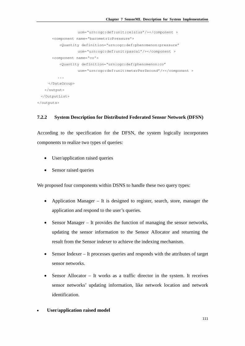
Chapter 7 SensorML Description for System Implementation
111
uom=“urn:ogc:def:unit:celsius”/></component >
<component name=“barometricPressure">
<Quantity definition=“urn:ogc:def:phenomenon:pressure”
uom=“urn:ogc:def:unit:pascal”/></component >
<component name=“co">
<Quantity definition=“urn:ogc:def:phenomenon:co”
uom=“urn:ogc:def:unit:meterPerSecond”/></component >
...
</DataGroup>
</output>
</OutputList>
</outputs>
7.2.2 System Description for Distributed Federated Sensor Network (DFSN)
According to the specification for the DFSN, the system logically incorporates
components to realize two types of queries:
• User/application raised queries
• Sensor raised queries
We proposed four components within DSNS to handle these two query types:
• Application Manager – It is designed to register, search, store, manager the
application and respond to the user’s queries.
• Sensor Manager – It provides the function of managing the sensor networks,
updating the sensor information to the Sensor Allocator and returning the
result from the Sensor indexer to achieve the indexing mechanism.
• Sensor Indexer – It processes queries and responds with the attributes of target
sensor networks.
• Sensor Allocator – It works as a traffic director in the system. It receives
sensor networks’ updating information, like network location and network
identification.
• User/application raised model

Chapter 7 SensorML Description for System Implementation
112
In a DFSN, the components mentioned above allow the basic functionality of a sensor
data collection network. We summarize two likely query methods and discuss the
numerous types of interactions between each component. They are named: ‘User
raised query’ and ‘Sensor raised query’. From the benefited of SensorML we can
present the query processing in details.
Figure 7-4 User raised model for DFSN
The process in Figure 7-4 is raised by users and applications and will be terminated
after the desired sensor data arrives or a message of ‘no result founded’ is returned.
This may be initiated by a user wants to check the current states of the environment in
a specific area or an applications needs to quote the historical sensor data for further
analysis. Figure 7-4 shows the user raised model sequence interactions between
components. From the very beginning, the user will send a query to the Sensor
Indexer to start the process. The format of that query is shown in Listing 7-7:
Listing 7-7. Create a Query and sent the query from user interface to sensor indexer <connection name="query">
<Link>
<source ref="userInterface/inputs/query/sensorInfo"/>
<destination ref="sensorIndexer/inputs/sensorIndexInfo/sensorInfo"/>
</Link>
</connection>
Once the query has been submitted, the Sensor Indexer will help return details such as

Chapter 7 SensorML Description for System Implementation
113
the destination data source (can be database or sensor networks) and classify the
query by interest duration. Listing 7-8 shows the query classify.
Listing 7-8. Classify the query <connection name="queryClassify">
<Link>
<source ref="userInterface/inputs/query/time"/>
<destination ref="this/time"/>
</Link>
</connection>
The sensor indexer sorts the queries into real-time queries and historical queries. A
query will be sent to the database if it is a historical query. Otherwise, it will connect
with the sensor allocator, which will respond with the allocating the network address.
Listing 7-9 shows how to set connection for a real-time query or a historical query.
Listing 7-9. Set a real-time query or a historical query connection <connection name="realtimeQuery">
<Link>
<source ref="sensorIndexer/outputs/realtimeQuery/sensorInfo"/>
<destination ref="sensorAllocator/inputs/sensorInfo"/>
</Link>
</connection>
<connection name="historicalQuery">
<Link>
<source ref="sensorIndexer/outputs/historicalQuery/sensorInfo"/>
<destination ref="database/inputs/query"/>
</Link>
</connection>
For a historical query, it returns the result and questions the user application whether
to build a connection with Historical database or to wait for the information from the
Sensor allocator to connect to the data source directly for data transmission.
Otherwise, the Sensor Allocator will ask both the data source and user application for
the connection details and helps them to build the connection. The function for
establishing a connection is shown below.
Listing 7-10. Establish a connection for data transmission <connection name="dataToUser">

Chapter 7 SensorML Description for System Implementation
114
<Link>
<source ref="this/dataSource/dataValue"/>
<destination ref="userInterface/outputs/outputValue"/>
</Link>
</connection>
<connection name="databaseToUser">
<Link>
<source ref="database/outputs/dataValue"/>
<destination ref="userInterface/outputs/outputValue"/>
</Link>
</connction>
The figure also describes the sensor register mechanism, which will create a new type
of sensor in sensor manager and then update the information in sensor index and
sensor allocator, as shown below.
Listing 7-11. Register a new type of sensor in sensor manager <connection name="sensorRegister">
<Link>
<source ref="dataSource/newSensor"/>
<destination ref="sensorManager/inputs/sensorInfo"/>
</Link>
</connection>
<classifier name="sensorType">
<Term definition="urn:ogc:def:classifier:OGC:1.0:sensorType">
<value>temp</value>
</Term>
</classifier>
The Sensor Indexer and Sensor Allocator will then be asked for information relating
to updates by the function shown in Listing 7-12. The sensor network’s details, such
as sensor type, location, setup time, owner etc., may vary.
Listing 7-12. Update the sensor indexer and sensor allocator separately <connection name="indexUpdate">
<Link>
<source ref="sensorManager/outputs/sensorIndex"/>
<destination ref="sensorIndexer/inputs/sensorIndexInfo"/>
</Link>
</connection>
<connection name="allocatorUpdate">
<Link>
<source ref="sensorManager/outputs/sensorAllocate"/>

Chapter 7 SensorML Description for System Implementation
115
<destination ref="sensorAllocator/inputs/SensorAllocateInfo"/>
</Link>
</connection>
• Sensor raised query
The sensor raised query happens when a value that exceeds the critical threshold has
been detected by the sensor network. The query is generated by notifying and the
Application manager to check whether there is any application that has registered to
monitor the exceptional value from the current sensor network. After that, the data
will be stored in the historical database if there is no application showing its interest,
or transmitted to the desired application if there is. Interactions within the Application
Manager and the sequence of the sensor raised query are shown in Figure 7-5.
Figure 7-5 Sensor raised query for DFSN
In one wireless sensor network, the data source that exceeds the given threshold or
registers with interested application, will be sent through the expectation alert()
function to application manager component. The alert is shown below.
Listing 7-13. Generate threshold alert and send expectation alert <connection name="thresholdAlert">
<Link>
<source ref="this/dataSource/dataValue"/>
<destination ref="dataSource/process/parameters/threshold"/>
</Link>

Chapter 7 SensorML Description for System Implementation
116
</connection>
<connection name="expectationAlert">
<Link>
<source ref="this/dataSource/dataValue"/>
<destination
ref="applicationManager/applicationInteretedName/interestedValue"/>
</Link>
</connection>
When the application manager component has received the alert query from data
source, it will process the query using the Application search() function to find out
the user who may be interested into this application. The application search function
is descripted by its ProcessChain (the ProcessChain defines a collection of processes
that are executable in a sequential manner to obtain a desired result. it has inputs,
outputs, and parameters properties (Botts M. and Robin A., 2007). First we define two
input component in the InputList that are “ApplicationInterestedName” and
“DataSource”. The “data record” is a field that also contains the user’s network
address. Finally all of the processes that are used in it are referenced and all above the
items’ connections are defined.
Listing 7-14. The format of interested application section <input name="applicationInterestedName">
<swe:DataRecord>
<swe:field name="interestedValue">
<swe:Quantity/>
</swe:field>
<swe:field name="userIP">
</swe:field>
</swe:DataRecord>
</input>
While process model provides metadata that is useful for sensor data discovering
and assisting humans, the properties that are critical for supporting the execution of
the Process Model within SensorML-enabled software are the inputs, outputs,
parameters, and method properties. The following example describes the process of
searching the target application from the application manager component. When
associated with SensorML-enabled software implementation, defined within the

Chapter 7 SensorML Description for System Implementation
117
method property, it serialises an executable process for searching all existing
applications.
Listing 7-15. The process chain for application search function <!--application manager-->
<components>
<ComponentsList>
<!--application search-->
<component name="applicationManager" xlink:arcole="urn:ogc:def:role:process">
<ProcessModel>
<inputs>
<InputsList>
<input name="applicationInterestedName">
<swe:DataRecord>
<swe:field name="interestedValue">
<swe:Quantity/>
</swe:field>
<swe:field name="userIP">
</swe:field>
</swe:DataRecord>
</input>
<input name="dataSource">
<swe:DataRecord>
<swe:field name="dataValue">
<swe:Quantity/>
</swe:field>
<swe:location gml:id="data_Location"
definition="urn:ogc:def:property:OGC:location">
</swe:location>
</swe:DataRecord>
</input>
</InputList>
</inputs>
<outputs>
<OutputList>
<output name="returnValue">
<swe:Quantity/>
</output>
</OutputList>
</outputs>
<parameters>
<ParameterList>
<parameter name="threshold">

Chapter 7 SensorML Description for System Implementation
118
<swe:Quantity/>
</parameter>
<parameter name="logic">
<swe:Category definition="urn:ogc:def:property:OGC:logic">
<swe:value>=</swe:value>
</swe:Category>
</parameter>
</ParameterList>
</parameters>
<method
xlink:href="urn:ogc:def:process:OGC:logicalCompare001"/>
</ProcessModel>
</component>
</ComponentsList>
</components>
The final stage of the process is building a connection and data transmission, which is
similar to the user raised query. The user or database can connect with the target
network directly.
Listing 7-16. Build connection from data source to user interface or database <connection name="dataToUser">
<Link>
<source ref="this/dataSource/dataValue"/>
<destination ref="userInterface/outputs/outputValue"/>
</Link>
</connction>
<connection name="dataToDatabase">
<Link>
<source ref="this/dataSource/dataValue"/>
<destination ref="database/inputs/inputsValue"/>
</Link>
</connection>
On the other hand, the following listing shows the user register function that is used to
establish the interested application for user and manage the users’ information for
further connection.
Listing 7-17. Set a user registration <connection name="userRigster">
<Link>
<source ref="userInterface/applicationInteredted/interestedValue"/>

Chapter 7 SensorML Description for System Implementation
119
<destination
ref="applicationManager/applicationInteredted/interestedValue"/>
</Link>
</connection>
7.2.3 System Description for 6LoWPAN Enabled Federated Sensor Network
(6EFSN)
We have proposed a system architecture discussed in chapter 6. It is very similar to
the previous DFSN, so the system description in SensorML is very similar. The
queries to the DSNS can also be divided into user raised queries and sensor raised
queries.
User Raised Query
Figure 7-6 User raised model for 6EFSN
Figure 7-6 is the sequence diagram for the user raised model of the 6EFSN system.
The Sensor Allocator is removed because the IPv6 enabled WSNs are much easier to
reach; the data source is replaced by 6LoWPAN sensor because the query can be
delivered to a specific node device with the support of 6LoWPAN standard. Therefore,
user raised real-time queries processed differently in DFSNs and 6EFSNs. The
relevant code is shown below.

Chapter 7 SensorML Description for System Implementation
120
Listing 7-18. Send real-time query to IPv6 Enabled Sensor <connection name="realtimeQuery">
<Link>
<source ref="sensorIndexer/outputs/realtimeQuery/sensorInfo/SensorIP"/>
<destination ref="IPv6Sensor/inputs/SesnorIP"/>
</Link>
</connection>
Sensor Raised Query
The Sensor Raised Query in 6EFSN is basically the same as the one in DFSN. The
only change in this diagram is to replace the Data Source to a 6LoWPAN Sensor; all
other components remain the same. The sequence diagram is shown in Figure 7-7.
Figure 7-7 Sensor raised model for 6EFSN
In a 6LoWPAN enabled FSN, a specific sensor node becomes easier to reach from an
external network. The process of building a connection between the data consumer
and the sensor node is IP based without address mapping. Listing 7-19 is the snippet
of getting connected with IPv6 sensor node.
Listing 7-19. Build connection with IPv6 sensor node <sml:component name="buildConnection">
<sml:ProcessModel gml:id="connectSensorNode">

Chapter 7 SensorML Description for System Implementation
121
<sml:inputs>
<sml:InputList>
<sml:input name="sensorID">
<swe:Category
definition="urn:ogc:def:input:NG::sensorInfo"/>
</sml:input>
</sml:InputList>
</sml:inputs>
<sml:outputs>
<sml:OutputList>
<sml:output name="SensorIP">
<swe:Category definition="urn:ogc:def:input:NG::sensorInfo"/>
</sml:output>
</sml:OutputList>
</sml:outputs>
<sml:parameter>
…
</sml:parameter>
<sml:method xlink:href="urn:ogc:def:method:NG::buildConnection"/>
</sml:ProcessModel>
</sml:component>
SensorML Profile Rules for FSN 7.3
The system description for three structures above is a SensorML instance that
conforms to the profile, which is described in the following. The system description
shall be harvestable by discovery services.
The open and flexible structure, such as FSN, are described by SensorML specifies
many elements are optional, allows expressing the same information in several,
differently structured ways. SensorML also realises the three FSN structures that can
be applied into different sensor networks. In order to ensure the structure can be
steadily handled by automatic harvesting mechanisms, there are some rules to define
the information, which must be encoded in the structure.
The following is intended to be primarily applied SensorML to set rules or formats for
FSN service. We assumed that the request of a single sensor network or application
description returns the entire model of a system to its affiliates. Since the entire

Chapter 7 SensorML Description for System Implementation
122
system model incorporates the associated sensor or application descriptions into
sensor or application manager, this approach enables several different WSNs to access
the information of the aggregating system, as well as allowing its associated
components in the FSN.
SensorML allows the formulation of separate rules that restrict an existing schema.
The original XML schema does not have to be modified. The set of rules that make up
the profile are presented below. The profile contains rules that restrict the System and
Component elements for FSN, respectively. They are shown in sections 7.3.2 and
7.3.3 respectively. First, section 7.3.1 describes the rules that must execute during the
validation process of every element types.
7.3.1 Common profile rules
In order to make sure that a list of keywords describing the sensor is provided in the
System, and use for intendedApplications() components, the rule shown in Listing
7-20 has been defined. The keyword should include all type of sensors and intended
applications.
Listing 7-20. The rule for ensuring that a KeywordList is provided <rule context="//sml:System">
<assert test="sml:keywords/sml:KeywordList">Error: 'KeywordList' element
has to be present</assert>
</rule>
<rule context="//sml:Component">
<assert test="sml:keywords/sml:KeywordList">Error: 'KeywordList' element
has to be present</assert>
</rule>
The rule defined in Listing 7-21 restricts the possible structure of the identification
section. Each listed identifier, such as identify the sensor type, has to contain the
definition attribute. The value of this attribute serves as a link to the semantic
description of the identifier. Listing 7-22 shows that every classification element must
contain a definition section. The definition can also improve the code readability for
other users.

Chapter 7 SensorML Description for System Implementation
123
Listing 7-21. The rule for ensuring that every identifier contains a definition <rule
context="//sml:identification/sml:IdentifierList/sml:identifier/sml:Term">
<assert test="string-length(@definition) > 0">Error: 'definition' attribute
has to be present and its value has to be > 0.</assert>
</rule>
Listing 7-22. The rule for ensuring that every classification element contains a definition
<rule
context="//sml:classification/sml:ClassifierList/sml:classifier/sml:Term">
<assert test="string-length(@definition) > 0">Error: 'definition' attribute
has to be present and its value has to be > 0.</assert>
</rule>
To be able to identify a system or a component uniquely, the rule in Listing 7-23 is
defined. According to SensorML document, one identifier of the identification section
must declare a definition attribute with the value
urn:ogc:def:identifier:OGC:1.0:uniqueID. Then the value of the identifier’s Term
element uniquely identifies the instance that can identify a uniqueID for each type of
sensor or application in our system. In OCG, they provide many unique IDs for
common sensors or applications, such as temperature.
Listing 7-23. The rule for ensuring that a uniquleID is provided <rule context="//sml:identification">
<assert
test="count(sml:IdentifierList/sml:identifier/sml:Term[@definition =
'urn:ogc:def:identifier:OGC:uniqueID']) = 1" >Error: one identifier has to
be of the type 'urn:ogc:def:identifier:OGC:uniqueID'.</assert>
</rule>
Furthermore each sensor shall process a long and a short name (e.g. Temperature and
temp in previous section). This is ensured by the rule shown in Listing 7-24.
Listing 7-24. The rule for ensuring that a longName and a shortName are provided <rule context="//sml:identification">
<assert
test="count(sml:IdentifierList/sml:identifier/sml:Term[@definition =
'urn:ogc:def:identifier:OGC:longName']) = 1" >Error: one identifier has to
be of the type 'urn:ogc:def:identifier:OGC:longName'.</assert>
</rule>
<rule context="//sml:identification">

Chapter 7 SensorML Description for System Implementation
124
<assert
test="count(sml:IdentifierList/sml:identifier/sml:Term[@definition =
'urn:ogc:def:identifier:OGC:shortName']) = 1" >Error: one identifier has to
be of the type 'urn:ogc:def:identifier:OGC:shortName'.</assert>
</rule>
7.3.2 System specific profile rules
A SensorML has to incorporate one member element that contains exactly one system.
In FSN, it has to contain more than one WSN. The rule is expressed by the following
listing.
Listing 7-25. The rule for ensuring that a member element contains exactly one system <rule context="/">
<assert test="count(sml:SensorML/sml:member) = 1">Error!</assert>
<assert test="count(sml:SensorML/sml:member/sml:System) =
1">Error!</assert>
</rule>
Each system must contain information about the time it is valid for. As the SensorML
schema defines this can either be a gml:TimePeriod or a gml:TimeInstant describing
the instant in time at which the stated metadata about the System has become valid. This
should be used in the database section or the application manager section when awaiting
data transmission or event detection in our system.
Listing 7-26. The rule for ensuring that every system a vaildTime element is provided <rule context="//sml:System">
<assert test="sml:validTime">Error: 'validTime' element has to be
present</assert>
</rule>
The components section of a system description lists the descriptions of the associated
sensors. The component element must contain either the attribute xlink:href to
specify an external reference to the sensor description, or a component such as a child
element, which describes the sensor inline. It can be used as a link between sensor
node and intended application. This condition is formulated in Listing 7-27.

Chapter 7 SensorML Description for System Implementation
125
Listing 7-27. The rule for ensuring that descriptions for the Components of a System are provided
<rule context="//sml:System/sml:components/sml:ComponentList/sml:component">
<assert test="(@xlink:href and not(sml:Component)) or (not (@xlink:href) and
sml:Component)">Error!</assert>
</rule>
7.3.3 Component specific profile rules
According to the common rules defined in section 7.3.1 a Component description has
to fulfil the rule specified in Listing 7-28. It defines that a Component element has to
contain at least one classifier with the definition
urn:ogc:def:classifier:OGC:1.0:sensorType. The value of its contained Term
element states the type of the sensor and the list of intended application, which we
used to, described the application and sensor register components in section 7.2.1.
Listing 7-28. The rule for ensuring that for every Component the sensor type is described
<rule context="//sml:Component/sml:classification">
<assert test=
"count(sml:ClassifierList/sml:classifier/sml:Term[@definition =
'urn:ogc:def:classifier:OGC:1.0:sensorType']) >= 1" >Error!</assert>
</rule>
Discussion 7.4
At the beginning of this chapter, we introduce the basic characters of the SensorML. It
is used to provide an information model and encodings that enable discovery and
tasking of web-resident sensors, and exploitation of sensor observations. On top of
that, we presented an approach for defining a SensorML profile that can be used for
sensor network and FSN service. The profile was developed under the three FSN
architecture description and aims to meet the requirements of FSN system design.
This work provides a comprehensive pointing for the future development to achieve
the FSN in a more compatible and easier way.

Chapter 8 Architectural Design of Internet of Things in Logistics Management for Emergency Response – A Case Study
126
Architectural Design of Chapter 8.Internet of Things in Logistics Management for Emergency Response – A Case Study
The Internet of Things (IoT) aims to connect individual smart “network enabled”
objects to the Internet using wireless/wired technologies for secure and efficient
deployment of services using these objects. Since the concept of the IoT was put
forward in 2005, we see the deployment of a new generation of networked objects
with communication, with sensory and action capabilities for numerous applications,
mainly in global supply chain management, environment monitoring and mobile
target tracking. One of the scientific and technical challenges in the design of the IoT
is the architecture design, which enables the interconnection of trillions of smart
objects. This chapter employs radio frequency identification (RFID) sensor networks
as smart “network enabled” objects and proposes a service-oriented IoT architecture
for logistics management.
The Gateway solution of the integration method which was introduced in Chapter 5 is
the one be selected for this case study. The core components of this system are
Domain Sensor Name Server, Sensor Service Publisher, Historical Database and

Chapter 8 Architectural Design of Internet of Things in Logistics Management for Emergency Response – A Case Study
127
RFID sensor networks. Using emergency response operation as a case study, this
chapter demonstrates the possible implementation and strategic values of the IoT
architecture in logistics management.
IoT in logistics supply chain management 8.1
Logistics is one of the main application areas where the IoT is considered a suitable
solution. Research of the technology level of the IoT challenge domains by applying
specific IoT enabling technologies, such as RFID, sensors and sensor networks, to the
field of logistics. Researchers have shown that by using RFID, the status of material
and vehicles can be tracked and monitored throughout the supply chain and in
logistics centres to increase delivery reliability in terms of correct material orders and
timely deliveries (Hamzehet al., 2007). More and more logistics centres are adopting
RFID systems to improve performance. Ngai (Ngai et al., 2007) presents their
findings of a case study on the development of a RFID prototype system integrated
with mobile commerce in a container depot. RFID has been employed at Shanghai
Port to replace the legacy IC card systems to track container trucks in the operation
zones (Shu et al., 2007). RFID-based real-time parts tracking system used at the
Oklahoma City Air Logistics Centre (OC-ALC) has successfully reduced service
times for aircraft by over 50%, resulting in the aircraft spending more time in the air
and less on the ground. The literature (Staake et al., 2005) has shown the potential of
using RFID systems to protect products against theft and plagiarism. Wal-mart, the
world’s largest retailer, has implemented RFID into its supply chain, which gives
them the ability to know where every item is in the supply chain (Roberti, 2003).
Sensors are also implemented in some logistics supply chain practices. In the Sydney
Port Intermodal Logistics Centre at Enfield, sensors are deployed with time switches
to control the comfort heating/cooling and light switches to optimise building
performance and system control strategies. A container tracking system has also been
tested at Berlin Inner-City Logistics Centre with temperature, pressure and humidity
sensors implemented to monitor the freight status, and movement and shock sensors

Chapter 8 Architectural Design of Internet of Things in Logistics Management for Emergency Response – A Case Study
128
for security monitoring. Those case studies demonstrated the potential of the enabling
technologies of the IoT in logistics management in identifying objects and monitoring
the condition and status of some particular freight with special needs.
Work has been also carried out to investigate the integration and interconnection of
those enabling technologies at the communication and networking level of the IoT.
Liu (Liu, 2007) used a field bus to connect sensors and RFID readers to a central
server, whilst Jedermann et al. (Jedermann et al., 2006) designed and implemented a
freight agent module to integrate RFID and Wireless Sensor Networks (WSN) in a
container for fruit logistics. A further improved system was recently presented by
Yang et al. (Yang et al., 2011) to seamlessly integrate RFID, sensors and WSNs into a
unified ZigBee system architecture, which is named as the ZigBee RFID Sensor
Network. However, most of the existing researches focus on a local system design and
a single-site and single-purpose implementation. For supporting the global vision of
the IoT, current systems lack scalability and flexibility to serve multiple applications
in the scope of a global supply chain.
Some researches, such as logisticians and information engineering practitioners, have
been advancing the intelligence level of the IoT. For example, (Ten Hompel, 2006)
considers autonomous transport of logistics objects from the sender to the delivery
address, whilst Thompson (Thompson et al., 2008) models a healthcare logistics in a
virtual world trying to illustrate the scenario and address social issues raised.
Numerous groups (Fleisch et al., 2005; Li et al., 2006; Li et al., 2006; Tajima, 2007)
have also quantified the performance improvement in terms of inventory reduction,
accuracy, cost and out-of-stock levels, and how the IoT and its enabling technologies
can provide for various types of supply chains. Most of these works focus particularly
on retail supply chains. They mainly target management and business models and are
usually based on the assumption that the pervasive network with the desired
identification and sensory data collection functionalities is already available.
Little has been done so far in the architecture design of the IoT for developing an

Chapter 8 Architectural Design of Internet of Things in Logistics Management for Emergency Response – A Case Study
129
efficient, reliable and flexible architecture for interconnecting distributed smart
‘network enabled’ objects globally for real-time requests. In this chapter, we first
combine RFID with wireless sensor networks for local comprehensive data collection,
and propose a service-oriented architecture of the IoT for global use in logistics
supply chain management. Emergency response operation scenario is used to
illustrate the implementation and strategic values in the use of the proposed IoT
architecture.
Requirements to the IoT for Logistics Supply Chain 8.2
Management
8.2.1 Comprehensive data sources
Global supply chain management deals with an integrated supply chain that ranges
from supply, purchase, production, transportation, storage, sale to consumption. The
accuracy and timeliness of the information collected from the supply chain at different
links is the key for logistics supply chain management. The lack of collecting and
sharing information likely makes the supply chain rupture and results in low
efficiency and resource waste. Traditionally, real-time information collected from
RFID tags is used in almost every link of supply chain ranging from commodity
design, raw material purchasing, production, transportation, storages, distribution and
sale. Unfortunately, RFID can only provide static information, such as product ID,
and manufacturing date etc. Dynamic information is required in order to monitor and
even control the changing environment and the status of products throughout the
supply chain to ensure smooth and efficient operation and to quickly respond to the
changeable market and exception environments. The continuous progress in
microelectronics and wireless communication techniques makes it now possible to
deploy various wireless sensor networks alongside the supply chain links. Hybrid
RFID sensor network is crucial for providing Who, What, When and Where (4Ws)
information to the IoT for supply chain management.

Chapter 8 Architectural Design of Internet of Things in Logistics Management for Emergency Response – A Case Study
130
8.2.2 Multiple users, multiple applications and multiple data sources
A logistics supply chain consists of multiple sites and multiple users located at
different geographical positions. This means multiple users need to access multiple
distributed sensory data sources simultaneously or sequentially. Furthermore, the
global supply chain usually concerns a globally deployed workflow that involves
various organizations. Each of them has their own applications requiring access to
multiple services in the network. Thus the design of the IoT for supply chain
management requires the functionality of feeding multiple applications with multiple
sensory data sources. Moreover, organizations in the global supply chain need to view
their information as a strategic asset and ensure that it flows with minimum delay and
distortion (Li et al., 2006). Minimum distortion requires that data sharing in the global
supply chain must be reliable, while the minimum delay means that the majority of
information is time critical, with some needing real-time transmission and the others
having time scale. In this case, the designed architecture of the IoT for supply chain
management should have a certain level of emergency mechanism to make sure that
the system suffers minimum data loss if anything goes wrong, and should also be
capable to reliably respond to multiple users’ data requirements within a specified
time delay. As a global supply chain management may have a relatively large number
of applications and information sources, the IoT needs to be optimized to handle a
huge amount of access requests.
8.2.3 Service-Oriented Architecture
Simply adopting the IoT enabling technologies, such as RFID and WSN, in a local
system is not enough. Global supply-chain management requires a supply chain-wide
information infrastructure, which is used to directly disseminate relevant market
information throughout the chain as a whole in order to avoid time loss. Thus an
efficient, reliable and low cost architecture that accommodates the various
technologies is needed. Additionally, it needs to be implemented throughout the
global supply chain to enable effective data sharing, which can enable more accurate

Chapter 8 Architectural Design of Internet of Things in Logistics Management for Emergency Response – A Case Study
131
services for various decision support systems in the logistics process.
Yang et al. (Yang et al., 2011) proposed a ZigBee RFID sensor network for
humanitarian logistics centre management as an all-in-one solution. This work
provided a reference system design to integrate and interconnect various IoT enabling
technologies in one unified on-site system architecture. In this chapter, however, we
go one step further and propose an Internet-based service-oriented architecture. Our
system integrates multiple RFID sensor networks from different locations to serve
various decision support system applications located throughout the global supply
chain. Additionally, it also enhances information communication by publishing,
registering, and consuming application functionality, namely services, over the IoT
architecture.
In the following two sections, we propose hybrid RFID sensor networks and
Internet-based service-oriented architecture respectively to meet the above
requirements raised in global supply chain management.
Combining RFID with WSN for Data Collection 8.3
Traditional data collection networks normally consist of either RFID tags with their
readers or interconnected wireless sensors. As discussed in the previous section,
global supply chain management needs data and information collected from both
RFID and wireless sensors to answer the four questions: Who, What, When and
Where. RFID provides the Who (ID). Most people usually think RFID can provide
‘Where’ at all times. Unfortunately, what RFID does is tell us where an object was the
last time it went through a reader. Combining RFID and WSNs can provide the What,
When and Where in an unified information infrastructure. With possible sensing
capabilities, sensor enabled RFID networks will become responsive and conscious of
the asset state and environmental conditions, from which we are able to ensure that
our goods are not only in specific locations, but also in an appropriate condition.

Chapter 8 Architectural Design of Internet of Things in Logistics Management for Emergency Response – A Case Study
132
Sensor enabled RFID networks can also be used in production line logistic
management. Tagging some core component/assembly and recording their
specifications would lead to quicker repairs or better maintenance. Tags made
writable, active and integrated with special sensors can meet the needs of feedback
status (temperature, pressure, humidity etc.) of the object tagged. Such a network can
also be responsible for the monitoring of manufacturing processes, tracking tagged
components and status of a product. Therefore, people can ensure that automated
processes are kept synchronized and product quality is under well control throughout
the manufacturing processes.
RFID network and sensor network can be combined by using the ‘reader as a sensor’
approach for active, passive, and semi-active RFID systems or by the ‘tag as a sensor’
approach for only active RFID systems (Yang et al., 2007).
In the ‘reader as a sensor’ approach, the conception of a ‘sensor’ is extended.
Generally a sensor is a device that responds to a stimulus of a particular type of
environmental condition or pursues a specific physical measurement. In the ‘reader as
a sensor’ approach, the concept of the sensor is extended to involve the RFID reader
device as a sensor. What a reader device ‘senses’ is the appearance, the approaching
or the passing of a RFID transponder/tag within its reading range. The RFID readers
and the sensor motes (units) of the sensor networks are considered to be in the same
layer in the unified system architecture. The sensor network gateway device, such as a
sensor coordinator acts as the gateway device between the RFID readers and the
external network. All information generated by the readers are sent to the users via the
sensor network gateway device. This ‘Reader as a sensor’ architecture can integrate
active, semi-active or even passive RFID networks as the reading procedure or the
communication between the tags and readers are very similar to the typical RFID
systems.
In the ‘tag as a sensor’ approach, the ‘sensor’ conception is also extended to treat the
RFID transponder/tag devices as a sensor. A transponder device ‘senses’ the unique

Chapter 8 Architectural Design of Internet of Things in Logistics Management for Emergency Response – A Case Study
133
identification code stored in the tag’s memory. When a tagged asset or a person goes
within the reading range of a reader device, the tag senses the identification code of
the asset or the person and transmits the identification code to the reader device. In
this case, the RFID tags and the sensor units are considered to be in one layer of the
unified architecture. The reader devices and sensor network router devices are in
another layer.
Figure 8-1 Hybrid RFID sensor network architecture (Yang et al., 2011)
Figure 8.1 illustrates an example for both ‘reader as a sensor’ and ‘tag as a sensor’
hybrid architecture. Here, RFID readers, active RFID tags, passive RFID tags,
wireless routing devices and wireless sensors form a unified network and connect
with an external server through a sensor gateway.
Internet-based Service-Oriented Architecture 8.4
Global supply chain management systems are difficult to implement and maintain.
The main reasons for this are the lack of an efficient, reliable, and low cost
architecture and the ever-changing demands for businesses and the vastly different
needs of different end users. Such demands and needs can be met by providing
customization functionality to the end users and organizations under a flexible
service-oriented architecture. In this section, we will describe the proposed

Chapter 8 Architectural Design of Internet of Things in Logistics Management for Emergency Response – A Case Study
134
Internet-based service-oriented architecture for the IoT in the application of global
supply chain management. We expect this IoT architecture support multiple users,
multiple applications and multiple data sources in the global supply chain applications.
Furthermore, it provides one unified platform to collect, share, process and query data
from distributed RFID sensor networks, and allow these RFID sensor networks to join
and leave the IoT without affecting the rest of systems.
Figure 8-2 IoT service-oriented architecture for supply chain management
Figure 8-2 shows the IoT architecture for global supply chain management, which
considers these needs. The main components are RFID sensor networks, Sensor
Service Publishers (SSP), distributed local historical database systems, and a Domain
Sensor Name Server (DSNS). The RFID sensor networks send their data via the SSP,
either to end users for responding to their queries or to the local databases for backup
if any change occurs. The DSNS works in a similar way to the Domain Name System
(DNS) in the Internet and points the received queries to a corresponding SSP, where
the response is formed first and then sent to the end-users over the Internet. The
dataflow between the end-users, the SSPs, the DSNS, and the local database systems
is illustrated in Figure 8-3. All communications in this Internet-based architecture are

Chapter 8 Architectural Design of Internet of Things in Logistics Management for Emergency Response – A Case Study
135
supported by TCP/IP, except the communication within the RFID sensor networks
where IEEE 802.15.4 and ZigBee are employed for data collection with low cost, low
rate and short range communications.
Figure 8-3 Dataflow of the IoT architecture for supply chain management
8.4.1 Sensor Service Publisher
Front-End Proxy approach, Gateway approach and TCP/IP Overlay approach are
three approaches of integrating low-rate wireless personal area network (LR-WPAN),
such as the above RFID sensor networks into an IP enabled architecture (Shelby et al.,
2009) like the Internet. The gateway approach is a traditional approach widely used
with non-IP wireless embedded networks and other vendor-specific solutions. In the
gateway approach, a gateway is introduced at the edge of the network to deal with the
IP services. The compression approach leads to the compression of the existing
protocols so they can be made suitable to use over the LR-WPAN. The proposed IoT
architecture for supply chain management shown in Figure 8-3 adopts the gateway
approach. The SSP is designed as an extended gateway for reporting its own RFID
sensor network’s characteristics, publishing the availability of collected data and
uploading these data to the Internet. The SSP is also a type of service provider. When

Chapter 8 Architectural Design of Internet of Things in Logistics Management for Emergency Response – A Case Study
136
it joins a RFID sensor network, the SSP maintains a connection between the RFID
sensor network and the Internet and responds to queries from the DSNS.
8.4.2 Local historical database
Decision-making in the global supply chain management requires adequate situation
assessment. However, this requires processing of large amounts of heterogeneous
sensory data and information from spatially dispersed sources such as the RFID
sensor networks described in the previous section. In traditional approaches sensory
data and other information are transferred to a server and processed centrally.
However, central processing has many disadvantages. For example, central
approaches suffer from inadequate communication and processing capacity,
vulnerability to single-point failures, and delay in real-time data fusion. In order to
avoid problems of centralized approaches, we introduce distributed local databases for
RFID sensor networks deployed. Using a warehouse as an example, a local database
is installed for storing any changing data collected by the RFID sensor network
deployed in and around the warehouse. The automatic data collection is even-driven
and trigged by any change in the warehouse. Data query is made by the end-users
over the Internet and pointed to the corresponding local database by the DSNS. The
response to the data query is managed by and sent from the local database systems.
8.4.3 Domain sensor name server
The Domain Sensor Name Server (DSNS) is a sensory data central indexing system
and works in a similar way to the Domain Name Server in the Internet. The DSNS
points the queries received from the end-users to a corresponding SSP or a
corresponding local sensor database where the required data is collected or saved,
which forms a response to the query first; the query is then sent to the end-users. The
DSNS features a sensor manager, an application manager, a sensor indexer and a
sensor allocator. Figure 8-4 illustrates the interaction and workflow between these
components: online exception data and offline exception data go to the end-users and

Chapter 8 Architectural Design of Internet of Things in Logistics Management for Emergency Response – A Case Study
137
the local database systems respectively; real-time data order goes to the identified
RFID sensor networks; and historical data order goes to the identified local database
systems.
Figure 8-4 Interaction between the components of the DSNS
• Sensor Manager is for sensor networks registration. It provides a mechanism
for registering new RFID sensor networks by specifying their types,
descriptions and names. In addition, it implements a maintenance function for
updating the characteristics of any previously registered RFID sensor
networks.
• Application Manager is designed to register the application information, such
as IP address, application functionality and the types of sensory data required.
The reason for storing this information is to notify these applications
whenever those RFID sensor networks capture any predefined exception data
for them.

Chapter 8 Architectural Design of Internet of Things in Logistics Management for Emergency Response – A Case Study
138
• Sensor Indexer provides a search engine, which implements the search
services in terms of the sensor type or sensor characteristic for registered
applications. The search engine searches the RFID sensor networks in terms of
the sensor type, location, and characteristic. If there is one or more RFID
sensor networks that can provide the specified type of sensory data, a positive
response will be fed to the Sensor Allocator, where a direct data transmission
link between the identified RFID sensor network and the data requester will be
arranged.
• Sensor Allocator is the most important and heavily loaded part of the DSNS. It
allocates a connection link between the data requester (i.e. an application) and
the data provider that is a SSP. There are two types of queries that may trigger
the Sensor Allocator:
Sensor raised queries: These occur once a RFID sensor network has detected any
predefined exception data and the data has been transmitted to the SSP. The SSP will
publish both properties of the data and the sensors that collected the data to the DSNS.
The Application Manager in the DSNS checks whether there is any registered
application interested in the detected exception data. If there is, the Application
Manager returns the identified application connection information to the Sensor
Allocator. The Sensor Allocator sends a connection request with a listening port
number to the application and waits for the connection confirmation from the
application. If there is no application interested in the detected exception data or there
is no connection confirmation received, the local database system saves the detected
sensory data for future use.
User raised queries: User raised query occurs when an application sends a search
request to the Sensor Manager of the DSNS and ask for a particular type of data. The
Sensor Indexer will search for any SSP registered in the DSNS that can provide the
data required by the application. The Sensor Allocator will return the details of the
identified SSP, including the IP address and the port number to the application where

Chapter 8 Architectural Design of Internet of Things in Logistics Management for Emergency Response – A Case Study
139
the user raised query was made. The SSP activates the listening port for receiving and
confirms connection requests from the application.
Implementation Issues 8.5
DSNS: As the DSNS works in a similar way to the DNS server on the Internet, SCO
Unix (The SCO Group, 2010) on which the DNS is based is chosen as the operation
system in the implementation of the DSNS. The SCO Unix supports five different
types of configurations: primary server, second server, caching-only server, slave
model server and client. The first four models match the features of the DSNS and
have been employed in building the DSNS.
SSP: The duties of the SSP include sensory data extraction, registration of the current
RFID sensor networks at the DSNS, and responds to the control commands received
from the DSNS. The SSP is implemented as an IP-enabled ZigBee router in the
ZigBee RFID sensor network. It consists of two parts: a sensory data extraction part,
i.e. RFID sensor network sink node, and a service publishing and query response part.
The sensory data extraction part collects the desired sensory data and transmits it to
the service publishing and query response part, where data reading, data publishing,
and service control are implemented. The service controller stores the connected
RFID sensor network specifications and is assigned an IP address by the Sensor
Allocator in the DSNS for data communication with the data requestors.
Local database system: The local database system is implemented in MySQL and
used to store any predefined exception sensory data. It is made Internet-available by
registering the database servers at the DSNS. For dealing with multiple data queries, a
thread pool approach is introduced in the local database system. The thread pool holds
a number of live threads for instant use. Reusing a thread for multiple tasks can
reduce the overhead and the response time caused by thread creation. The local
database system may dynamically adjust the number of threads in the thread pool if
the number of data queries increase to a level higher than a certain threshold.

Chapter 8 Architectural Design of Internet of Things in Logistics Management for Emergency Response – A Case Study
140
End-user applications: There are two categories of end-user applications that query
and consume data provided by the IoT architecture: standalone applications and
web-based applications. The standalone applications are an individual client programs
for heavy data usage users who need to regularly check the sensory data and request
data from the fixed RFID sensor networks. It can be programmed in JAVA to ensure
cross platform usability. The web-based applications are for the users who just want to
do a quick look, but do not wish to install monitoring software in advance on their
local computers. The web-based applications contain the basic functions, like logging
in/out, searching, registering various interests and displaying sensory data. It can be
coded in Java Server Pages (JSP) or other web programming languages. The
communication protocol between end-users, the SSP, and the DSNS is the TCP/IP.
The IP enabled LR-WPAN protocol is used at the SSP to build an upper link with the
Internet and a down link with the RFID sensor networks.
Strategic Values of the IoT architecture in Logistics 8.6
Management for Emergency Response Operation
Logistics has always been considered as an important factor in emergency response
operations. When disaster strikes, first response teams need not only to rescue and
support civilians in the disaster area, but also maintain their capability of fighting the
disaster in the short- and long-term. Logistics includes rescue equipment, vehicles and
on-site staff as well as food, medicine and general living goods.
8.6.1 System implementation in Logistics management for emergency
response operations
The emergency response operations require the participation of a wide range of
organisations, including fire brigades, police forces, ambulance services, local or
national public sectors, and humanitarian aid organisations such as the British Red
Cross etc. Extensive information and resource sharing or other cooperation between
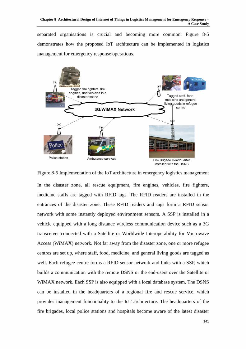
Chapter 8 Architectural Design of Internet of Things in Logistics Management for Emergency Response – A Case Study
141
separated organisations is crucial and becoming more common. Figure 8-5
demonstrates how the proposed IoT architecture can be implemented in logistics
management for emergency response operations.
Figure 8-5 Implementation of the IoT architecture in emergency logistics management
In the disaster zone, all rescue equipment, fire engines, vehicles, fire fighters,
medicine staffs are tagged with RFID tags. The RFID readers are installed in the
entrances of the disaster zone. These RFID readers and tags form a RFID sensor
network with some instantly deployed environment sensors. A SSP is installed in a
vehicle equipped with a long distance wireless communication device such as a 3G
transceiver connected with a Satellite or Worldwide Interoperability for Microwave
Access (WiMAX) network. Not far away from the disaster zone, one or more refugee
centres are set up, where staff, food, medicine, and general living goods are tagged as
well. Each refugee centre forms a RFID sensor network and links with a SSP, which
builds a communication with the remote DSNS or the end-users over the Satellite or
WiMAX network. Each SSP is also equipped with a local database system. The DSNS
can be installed in the headquarters of a regional fire and rescue service, which
provides management functionality to the IoT architecture. The headquarters of the
fire brigades, local police stations and hospitals become aware of the latest disaster

Chapter 8 Architectural Design of Internet of Things in Logistics Management for Emergency Response – A Case Study
142
development and response progress through the IoT architecture. Logistics demands
from the first response teams and refugee centres are made aware to the
corresponding organisations as well.
8.6.2 Strategic benefits of the IoT architecture for emergency response
operations
As mentioned in the previous section, there are enormous potential benefits of
adopting the proposed IoT architecture in logistics management for emergency
response operations. This section identifies strategic benefits of them from the
fundamental characteristics of what the proposed IoT architecture is or does: (i) the
IoT architecture is global and real-time; (ii) sensing is wireless and the collected data
are comprehensive; and (iii) it monitors environment and traces mobile objects.
The first fundamental characteristic of the proposed IoT architecture is being a global
and real-time solution. It perfectly fits the distributed feature of general logistics
management, particularly emergency response operations. Firstly, because the IoT
architecture is Internet-based or other wide-area network-based, the scope of the
architecture has no physical boundary. Any object linked with the network can be
incorporated into the architecture. In disaster situations, decision makers must respond
appropriately to different adverse situations. Effective emergency response operation
relies on sufficient supplies of emergency attacking forces and resources. The global
IoT architecture makes the progress in disaster attacking remotely visible. Therefore,
resources can be best allocated and delivered to the disaster scene. Secondly, the data
communication is real-time or almost real-time over the IoT architecture. Real-time
data meets the decision-making needs of command and control personnel in dynamic
disaster response operations and enables the cooperation between multiple
organisations and between multiple operators within a same organisation.
The second characteristic of the proposed IoT architecture is being wireless, which
possesses the ability to provide a comprehensive type of data for logistics

Chapter 8 Architectural Design of Internet of Things in Logistics Management for Emergency Response – A Case Study
143
management. The RFID sensor network in the IoT architecture integrates RFID
network and wireless sensor network into a unified information infrastructure. RFID
readers do not require physical contact with their tags, and wireless sensors sense the
environment and transmit the reading to the receivers over-the-air. No line of sight is
required in the RFID sensor network for their sensing tasks. Batch reading is possible,
which means that multiple tags and sensors can be read simultaneously. This feature
significantly increases efficiencies in logistics management, which is absolutely
important in disaster response and humanitarian aid operations as the situations may
dramatically change in few minutes. RFID sensor networks provide a comprehensive
scope of data about the 4Ws (Who, What, When and Where), which is a unique
identifier not only to an object, but also to the environment where the object exists.
We argue these 4Ws information better support logistics management than RFID only,
which can only provide a unique identifier to an object.
The third characteristic of the proposed IoT architecture is the ability to monitor the
environment and trace mobile objects. By combining RFID sensor networks with
other technologies, such as global positioning system (GPS), or infrared sensor
detection, RFID sensor networks provide the ability of wireless, real-time monitoring
and tracking of any tagged mobile objects in an indoor or outdoor environment to
provide complete visibility in the logistics management. Such visibility would enable
instant response to any exception event, distributed information sharing among
multiple organisations and multiple users.
Figure 8-6 summarises the strategic benefits that the IoT architecture can achieve
through the above three characteristics. It is notable that all the benefits are realised in
three ways: information sharing, information retrieving, and information explanation.
Li and Visich (Li et al., 2006) and Tajima (Tajima, 2007) compiled a comprehensive
list of benefits across the supply chain by using RFID technologies, such as reduced
shrinkage, reduced material handling and lower inventory. The benefits given in
Figure 8-6 show the benefits given by Li and Visich (Li et al., 2006) and Tajima
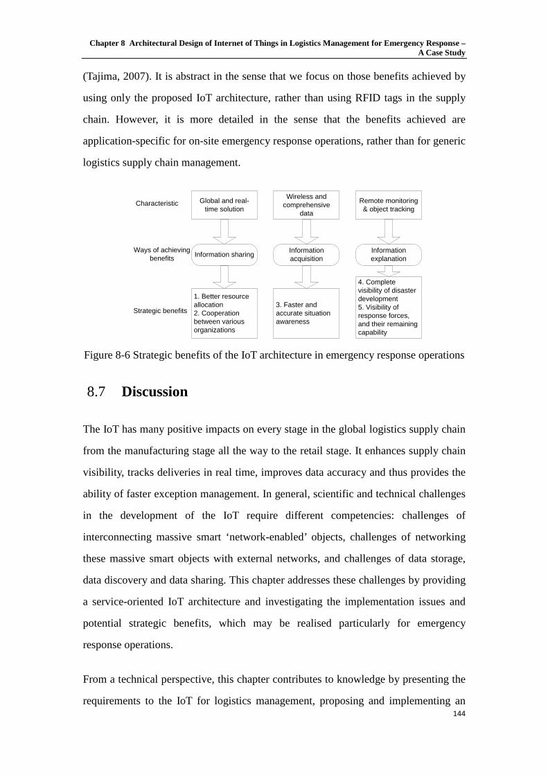
Chapter 8 Architectural Design of Internet of Things in Logistics Management for Emergency Response – A Case Study
144
(Tajima, 2007). It is abstract in the sense that we focus on those benefits achieved by
using only the proposed IoT architecture, rather than using RFID tags in the supply
chain. However, it is more detailed in the sense that the benefits achieved are
application-specific for on-site emergency response operations, rather than for generic
logistics supply chain management.
Global and real-time solution
Wireless and comprehensive
data
Remote monitoring & object tracking
Information sharing Information acquisition
Information explanation
1. Better resource allocation2. Cooperation between various organizations
3. Faster and accurate situation awareness
4. Complete visibility of disaster development5. Visibility of response forces, and their remaining capability
Characteristic
Ways of achieving benefits
Strategic benefits
Figure 8-6 Strategic benefits of the IoT architecture in emergency response operations
Discussion 8.7
The IoT has many positive impacts on every stage in the global logistics supply chain
from the manufacturing stage all the way to the retail stage. It enhances supply chain
visibility, tracks deliveries in real time, improves data accuracy and thus provides the
ability of faster exception management. In general, scientific and technical challenges
in the development of the IoT require different competencies: challenges of
interconnecting massive smart ‘network-enabled’ objects, challenges of networking
these massive smart objects with external networks, and challenges of data storage,
data discovery and data sharing. This chapter addresses these challenges by providing
a service-oriented IoT architecture and investigating the implementation issues and
potential strategic benefits, which may be realised particularly for emergency
response operations.
From a technical perspective, this chapter contributes to knowledge by presenting the
requirements to the IoT for logistics management, proposing and implementing an

Chapter 8 Architectural Design of Internet of Things in Logistics Management for Emergency Response – A Case Study
145
Internet-based service-oriented architecture to meet the identified requirements. The
SSP makes the sensory data collected from the associated RFID sensor network
network-available. The DSNS designed for the IoT management works in a similar
way to the Domain Name Server in the Internet and is efficient, reliable and flexible.
From a decision-making and information management perspective, this case study
contributes to knowledge by identifying the strategic benefits that may be realised in
emergency response operations through applying the proposed IoT architecture. The
benefits include better resource allocation, cooperation among multiple participants in
emergency operations, faster and accurate situation awareness of disaster scenes,
complete visibility of disaster development, response forces, and their remaining
capability. The ways of achieving these strategic benefits are through information
acquisition, information sharing and information explanation. These benefits are
derived as emergency response specific, but expected to apply for a wide range of
logistics management applications, where both static and dynamic information are
required.
The major limitation of this research is a lack of large scale empirical support and
evaluation of the IoT architecture, despite it working perfectly in our experiments.
When a large number of RFID sensor networks join the IoT, several technical
difficulties are expected. For example, the data flow to the DSNS may significantly
increase and a bottleneck may occur. Another obvious challenge in the real
application of the proposed IoT architecture is security and data confidentiality among
various data providers and data consumers. This problem is a common challenge
faced by any collaborative platform based on a public communication media, such as
the Internet.

Chapter 9 Conclusions and Future Work
146
Conclusions and Future Chapter 9.Work
Summary 9.1
The Internet of Things (IoT) is currently one of the hottest research topics; this
includes wireless sensor network (WSN), Radio Frequency Identification (RFID),
network integration and in-network processing etc. WSN is one of the related topics
focusing on monitoring and control. It is a fast-growing technology that has shown
great potential in future applications. A hybrid sensing and monitoring application is
always expected to answer four questions: Who, What, When and Where (4Ws), and
neither of the two technologies is able to provide complete information for all of them.
The Sensing parts like WSN and RFID technologies can provide information but lack
the ability of data sharing, which means they cannot provide a complementary 4Ws. A
federated system that integrates the various WSNs and the Internet gives a complete
answer to the 4Ws and is promising for information systems in future sensing and
monitoring applications.
This Thesis demonstrates the research that has been carried out so far on the subject
of Federated Sensor Network (FSN). The review of related technologies gives a
comprehensive introduction of the popular technologies related to FSNs called “the

Chapter 9 Conclusions and Future Work
147
Internet of Things”, which refers to the networked interconnection of everyday
objects. It is generally viewed as numerous self-configuring WSNs that aim to
interconnect all things. The fundamental purpose of the IoT is to make anytime,
anywhere connections between humans and other humans, humans and objects, even
objects and objects. In addition, the IoT also needs the ability to compare, identify and
filter incoming information from sensors. The IoT can be considered as the extension
of the Internet. It enriches the Internet resources by feeding in information from the
real world. The investigation of the 6LoWPAN helps us to address the challenges of
IoT deployment and brings IPv6 into the world of IoT. A decade has passed since the
IoT concept has been proposed. However, until now, there is no IoT specific standard,
such as modelling, algorithm and protocol published. Chapter 2 analyses the current
problems of the IoT modelling method and points out the possible solutions. With the
rapid development of integrated circuit, more and more products have Internet
accessibility, like TV, Blue-Ray player, fridge etc. Just like what Paul Otellini (the
CEO of Intel) talked in 2008 Intel Developer Forum (IDF): “In future, all the
electricity products will be connected into the Internet”. Nowadays, the network
system has become the key part of the IoT. RFID and WSN technologies will be
combined with the Internet and become a more complete information system. At the
end of this thesis, the case study based on the IoT combines the recent developed
technology to improve the situation of logistic service, identify the strategic
advantages after IoT getting involved and address the lack of current technique
development.
In the later part of this thesis, the development of FSN is carried out. These can be
divided into three different solutions: the Front-End Proxy solution, the Gateway
solution and the TCP/IP Overlay solution. All of these three solutions have been
investigated, improved and demonstrated. In the Front-End Proxy solution, we
introduced a centralized federated sensor network. After the demonstration we found a
centralized architecture makes it difficult to build a large scale federated system
because increasing data processing and query processing may case the system to

Chapter 9 Conclusions and Future Work
148
become very inefficient. Then, we introduce the Gateway solution. It solves the
problem of the Front-End Proxy solution by separating the query process and data
transmission. At the end, the TCP/IP Overlay solution is carried out from the
requirement of iNet localisation and tracking system. It is a localisation and tracking
system aimed to provide functional vehicle tracking in the manufactory parking yard.
With the benefits of 6LoWPAN, applications from external networks can easily access
the specific sensor node by its IPv6 address. This reduces the response time
significantly and systems can be easily deployed to cover the whole area with
multiple sensor networks. A comparison table of three types of integration solutions
between localization and tracking application and emergency response case study is
listed below.
Table 9-1Comparison of integration solutions
Finally, we introduced the SensorML to represent the three systems in details. It is the
general model and XML encoding for sensors and observations and measurements.
With its help, the federated sensor network system can be easily built by the
professional programing group for large applications in the IoT concept.
Contributions 9.2
This thesis aims to develop a framework for the IoT. The research in this thesis is

Chapter 9 Conclusions and Future Work
149
based on ZigBee/IEEE802.15.4, which is currently the most widely used WSN
technology. Three possible architectures of integrating the WSN and the Internet have
been presented. The contribution of this thesis to knowledge can be split into five
parts.
Firstly, we proposed the centralized federated sensor network, which is based on the
front-end proxy solution of integration between WSN and the Internet. After
introducing the structure and the reactions between different components, we
presented detailed infrastructure and the core component named virtual coordinator.
This architecture is able to deal with multiple WSN and feed sensor data to multiple
data consumptions. Demonstration systems based on the proposed architecture with
two ZigBee based WSNs are used to validate the designs.
Secondly, we proposed a distributed federated sensor network using the gateway
solution of the integration. We discussed the features of the centralised architecture
and noticed that design is usually developed for small and simple scenarios. In large
and complex systems, a centralized architecture may case a serious delay or even
system failure. We presented and discussed a distributed system, which separates the
data flow and query flow, as in a hybrid system. It presents a unified and flexible
system with a “DSNS” build-in, which borrows the concept of DNS on the Internet to
serve sensor networks. A demonstration system of the architecture was developed
based on ZigBee WSN to validate the design.
Thirdly, we proposed the enhanced architecture that is IPv6 enabled from the TCP/IP
overlay integrate solution. The previous integration solutions separate the WSN and
the Internet by a gateway or a proxy server that leads to high communication delay.
The 6LoWPAN provides a convenient method for both external application and
WSNs to get direct access to each other. With the benefit of IP-address-banded sensor
nodes, the system is able to handle multiple real-time aware applications like indoor
tracking and military monitoring. And also, a demonstration system validates the
design.

Chapter 9 Conclusions and Future Work
150
Fourthly, we presented an implementation for the iNet localisation and tracking
project by using the 6LoWPAN based FSN as the infrastructure of the system. It
shows the feasibility of transferring the real-time data over a federated sensor network.
And also implement a localisation and tracking system by fingerprinting algorithm
based on WSN.
Fifthly, we completed the FSN systems’ components and processes description in
SensorML, and presented them with UML sequence diagrams for the proposed FSN
architectures. This work will make our FSN concept much easier be understand and
re-built, it also provides a more compatible and easier way for the future development
to achieve the FSN even the Internet of Things.
Sixthly, we conducted a case study of the proposed architecture in logistics
management scenario for Emergency Response. We analysed the requirements of
information infrastructure for a logistics management system. By discussing the
implementation of a federated sensor network that integrates various WSN and the
Internet, we concluded that the system is able to meet the requirement of providing
information acquisition, information sharing and information explanation. By
properly implementing the federated sensor network, the visibility of resources and be
increased. That provides the ability of faster exception management as an emergency
response application.
In summary, all the objectives listed in Chapter 1 have been achieved. The objective
for logistic management related IoT architectural design is completed. We haven’t
done the field trial for the case study because of the limitation of resources. We
proposed a series of different architectures for the integration of various WSNs with
the Internet using different solutions. We also demonstrated the proposed architectures
through experimental implementation and laboratory testing. The tests have verified
the feasibility and features of our designs. At the end, these three systems are realised
in SensorML for formal development and construction in the future.

Chapter 9 Conclusions and Future Work
151
Future Work 9.3
Based on the study of existing work carried out so far, future work should be targeted
at providing reasonable Quality of Service for the DSNS. This work may also lead to
the research on the dynamically adapting for different scales of the FSN systems.
Secondly, the 6LoWPAN enabled system may face to the problem of network security
as the sensor nodes are exposed on the Internet directly. There can be achieved by
developing a functional lightweight firewall; or by enhancing the security mechanism
on the individual 6LoWPAN enabled sensor device, such as implanting a strong
authentication before connecting to the individual sensor node. Thirdly, the research
of FSN is focused on the development of integrating the Internet and WSNs, but other
technology might be able to join the system, like the cloud computing, to for a
collaboration of novel technologies to create the future Internet of Things.
References
152
References
[1] Akyildiz, I. F.; Kasimoglu, I. H., “Wireless Sensor and Actor Networks:
Research Challenges”, Elservier Ad Hoc Networks, Vol. 2, No. 4, pp. 351–
367, 2004.
[2] Akyildiz, I. F.; Pompili, D.; Melodia, T., “Challenges for Efficient Communi-
cation in Underwater Acoustic Sensor Networks”, ACM Sigbed Review, Vol.
1, No. 2, pp. 3–8, 2004.
[3] Akyildiz, I. F.; Pompili, D.; Melodia, T., “Underwater Acoustic Sensor Net-
works: Research Challenges. Elsevier Ad Hoc Networks”, Vol. 3, No. 3, pp.
257–279, 2005.
[4] Arnstein, L.; Grimm, R.; Hung, C. et al. “Systems support for ubiquitous
computing: A case study of two implementations of Labscape”. In Pervasive
'02: Proceedings of the First International Conference on Pervasive
Computing, pp. 30-44, Zurich, Switzerland, 2002.
[5] Association Institutes Carnot, “White paper: Smart networked objects &
Internet of Things”, 2011,
http://www.instituts-carnot.eu/files/AiCarnot-White_Paper-Smart_
Networked_ Objects_and_Internet_of_Things.pdf

References
153
[6] Baker, C. R.; Armijo, K.; Belka, S. et al., “Wireless sensor networks for home
health care”, AINAW, Ontario, Canada, 2007.Moteiv, <http://moteiv.com>.
[7] Bassi, A., “Internet of Things in 2020: Roadmap for the future”. EPoSS, Vol
1.1, May, 2008.
[8] Botts M.; Percivall G.; Reed C.; Davidson J., “OGC® Sensor Web
Enablement: Overview And High Level Architecture.” OpenGIS® White
Paper, Ref: OGC07-165, 2007.
[9] Botts M.; Robin A., “OpenGIS® Sensor Model Language (SensorML)
Implementation Specification” OpenGIS® Implementation Specification, Ref:
OGC07-000, 2007.
[10] Braun, T.; Voigt, T.; Dunkels, A., “TCP support for sensor networks”,
Proceedings of the Fourth Annual Conference on Wireless on Demand
Network Systems and Services (WONS 2007), Obergurgl, Austria, pp.
162-169, 2007.
[11] Broll, G.; Rukzio, E.; Paolucci, M.; Wagner, M.; Schmidt, A.; Hussmann, H.,
“PERCI: pervasive service interaction with the internet of things”, IEEE
Internet Computing 13 (6), pp. 74-81. 2009.
[12] Conduit, J.; Mavondo, F.T., “How critical is internal customer orientation to
market orientation”, Journal of Business Research, Vol. 51, pp. 11-24. 2001.
[13] Cook, D.; Das, S., “Smart Environments: Technologies, Protocols, and
Applications”, Wiley-Insterscience, ISBN 0-471-54448-5. 2004.
[14] Crossbow Technology, online, http://www.xbow.com.
[15] Dai C.; Yang S.; Knott R., “Data transfer over the Internet for real time
applications”. International Journal of Automation and Computing 4, pp.
414-424, 2006
[16] Dai, H.; Han, R., “Unifying micro sensor networks with the Internet via
overlay networking”, Proceeding of the 29th Annual IEEE International

References
154
Conference on Local Computer Networks (LCN’04), 2004.
[17] Darianian, M.; Michael, M.P., “Smart home mobile RFID based
Internet-Of-Things Systems and services”, Advanced Computer Theory and
Engineering, ICACTE’08, pp. 116-120, 2008.
[18] Dickerson, R.; Lu, J.; Lu, J.; Whitehouse, K., “Stream Feeds: an Abstraction
for the World Wide Sensor Web”, Proceedings of the Conference on the
Internet of Things (IOT 2008), Zurich, Switzerland, pp. 360-375, 2008.
[19] Dunkels, A.; Alonso, J.; Voigt, T.; Ritter, H.; Schiller, J., ”Connecting
Wireless Sensornets with TCP/IP Networks”, Wired/Wireless Internet
Communications, Lecture Notes in Computer Science, 2957, pp. 583-594,
2004.
[20] Dunkels, A.; Alonso, J.; Voigt, T., “Making TCP/IP Viable for Wireless
Sensor Networks”, In Proc. EWSN, Janpan. 2004.
[21] Dunkels, A., “Towards TCP/IP for Wireless sensor Networks”, Malaralen
University Licentiate Thesis No.45, Swedish Institute of Computer Science,
March 2005.
[22] European Commission, “Internet of Things Strategic Research Roadmap”.
CERP-IoT , 2009.
http://www.internet-of-things-research.eu/pdf/IoT_Cluster_Strategic_Researc
h_Agenda_2009.pdf
[23] Estrin, D.; Govindan, R.; Heidemann, J.; Kumar, S., “Next century
challenges: Scalable coordinate in sensor network”. Proceedings of the 5th
ACM/IEEE International Conference on Mobile Computing and Networking.
Seattle: IEEE Computer Society, pp. 263-270, 1999.
[24] Fall, K., “A Delay-Tolerant Network Architecture for Challenged Internets”.
In Proc. SIGCOMM, New York, Aug. 2003.
[25] Fan, W.; Zhang, K.; Cheng, H.; Gao, J.; Yan, X.; Han, J.; Yu, P., Verscheure

References
155
O., “Direct mining of discriminative and essential frequent patterns via
model-based search tree”, the 14th ACM SIGKDD, ISBN:
978-1-60558-193-4, 2008.
[26] Fleisch, E.; Tellkamp, C.; “Inventory inaccuracy and supply chain
performance: a simulation study of a retail supply chain”, International
Journal of Production Economics, 95 (3), pp. 373-385, 2005.
[27] Fleisch, E., “What is the Internet of Things?”, Technical report, ETH Zurich /
University of St. Gallen, WP-BIZAPP-053, 2010.
[28] Fok, CL.; Julien, C.; Roman, GC.; Lu, CY., “Challenges of satisfying
multiple stakeholders: quality of service in the internet of things”. SESENA
'11 proceeding of the 2nd workshop on Software engineering for sensor
network applications, 2011.
[29] Foster, I.; Kesselman, C.; Nick, J.; Tuecke, S., “Grid services for distributed
systems integration”. IEEE Computer, 35(6), 2002.
[30] Gaynor, M.; Moulton, S.L.; Welsh, M.; LaCombe, E.; Rowan, A.; Wynne, J.,
"Integrating wireless sensor networks with the grid," Internet Computing,
IEEE, vol.8, no.4, pp.32-39, July-Aug. 2004
[31] Gershenfeld, N. (1999): “When Things Start to Think”. Agent Systems and
Applications, 1999 and Third International Symposium on Mobile Agents.
Proceedings. First International Symposium on, pp. 118-129, 1999.
[32] Gershenfeld, N.; Krikorian, R.; Cohen, D., “The Internet of Things”,
Scientific American. 291 (4), pp. 76-81. 2004.
[33] Govindan, R.; Hellerstein, J.; Hong, W.; Madden, S.; Franklin, M.; Shenker,
S., “The Sensor Network as a Database”. Computer Science Department,
University of Southern California. Technical Report pp. 02-771. 2002.
[34] Hamzeh, F.; Tommelein, I.D.; Ballard G.; Kaminsky, P., “Logistics Centers to
Support Project-based Production in the Construction Industry”, in: C.L.

References
156
Pasquire and P. Tzortzopoulos (eds), Proceedings of the 15th Annual
Conference of the International Group for Lean Construction (IGLC 15), East
Lansing, MI., pp. 181-191, 2007.
[35] HART Communication Foundation, October 2010.
http://www.hartcomm.org/
[36] Heile, B., “Wireless Sensors and Control Networks: Enabling New
Opportunities with ZigBee”. http://www.ZigBee.org.
[37] Heinzelman, W.; Chandrakasan A.; Balakrishnan, H., “Energy-Efficient
Communication Protocol for Wireless Microsensor Networks”. Proc. 33rd
Hawaii Int’l. Conf. Sys. Sci. 2000.
[38] Ho, T. K., “Random Decision Trees”, IEEE Computer Society Washington,
DC, USA, ISBN: 0-8186-7128-9, 1995.
[39] Huang, A.; Steenkiste, P.,” Network-Sensitive Service Discovery”. Journal of
grid computing 1(3), pp. 309-326, 2004.
[40] IETF, “IPv6 over IEEE 802.15.4 low-power wireless personal-area-network”,
2007. http://www.6lowpan.org/
[41] Ilic, A.; Staake, T.; Fleisch, E., “Using sensor information to reduce the
carbon footprint of perishable goods”, IEEE Pervasive Computing 8 (1), pp.
22–29, 2009.
[42] Intanagonwiwat, C.; Govindan, R.; Estrin, D., “Directed Diffusion: A
Scalable and Robust Communication Paradigm for Sensor Networks”, Proc.
ACM MobiCom 2000, Boston, MA, pp. 56-67, 2000.
[43] Intanagonwiwat, C.; R. Govindan, et al., "Directed Diffusion for Wireless
Sensor Networking." Proceedings of the 1st ACM international workshop on
wireless sensor networks and applications, pp. 2-16, 2003.
[44] IPv6 over Low-Power Wireless Personal Area Networks (6LoWPANs),
http://www.ietf.org/. Operational Considerations and Issues with IPv6

References
157
DNS (RFC 4472).
[45] ITU, "The Internet of Things“. ITU Report, Genf., 2005.
http://www.itu.int/osg/spu/publications/internetofthings/
[46] Jedermann, R.; Behrens, C.; Westphal, D.; Lang, W., “Applying Autonomous
sensor systems in logistics—Combining sensor networks”, RFIDs and
software agents, Sensors and actuators A: Physical, 132 (1), pp. 370-375,
2006.
[47] Jirka, S.; Bröring, A., “SensorML Profile for Discovery Engineering Report”,
Public Engineering Report, Ref: OGC09-033, 2009.
[48] Kansal, A.; Nath, S.; Liu, J.; Zhao, F.; “SenseWeb: An Infrastructure for
Shared Sensing”, IEEE Multimedia, Vol. 14, no. 4, pp. 8-13, 2007.
[49] Kansal, A.; Nath, S.; Liu, J.; Zhao, F., “SenseWeb: An Infrastructure for
Shared Sensing”, IEEE multimedia, 14(4), pp. 8-13. October 200Sheth, A.;
Henson, C.; Sahoo, S.S., "Semantic Sensor Web," Internet Computing, IEEE,
vol.12, no.4, pp.78-83, July-Aug. 2008.
[50] Kim, J.; Kim, D.; Kwak H.; Byun, Y., “Integration between WSNs and
Internet Based on Address Internetworking for Web Service”, Computing and
Information, Vol. 27, pp. 707-718, 2008.
[51] Kinney, P., “ZigBee Technology: Wireless Control that Simply Works”.
Communications Design Conference, 2003.
[52] Kosanovic, M. R.; Stojcev, M. K., “Implementation of TCP/IP Protocols in
Wireless Sensor Networks”, Proceedings of the XLII International Scientific
Conference on Information, Communication and Energy Systems and
Technologies, (ICEST 2007), Ohrid, Macedonia, pp. 143-146, 2007.
[53] Kosanovic, M. R.; Stojcev, M.K., “Connecting Wireless Sensor Networks to
Internet”, Mechanical Engineering, Facta University, Vol. 9, No. 2, pp.
169-182, 2011.

References
158
[54] Kulik, J.; Heinzelman, W. R.; Balakrishnan, H., “Negotiation-Based
Protocols for Disseminating Information in Wireless Sensor Networks”.
Wireless Networks, vol. 8, pp. 169-85, 2002.
[55] Kumar, V.; Thomas, J.; Abraham, A.,“Secure Directed Diffusion Routing
Protocol for Sensor Networks using the LEAP Protocol”, IOS Press, 2006.
[56] Lambert, D.M.; Stock, J.R.,“Strategic Logistics Management”, Irwin, pp. 862,
1993.
[57] Ledlie, J.; Shneidman, J.; Welsh, M.; Roussopoulos, M.; Seltze, M,“Open
problems in Data Collection Networks”. Proceedings of the 11th workshop on
ACM SIGOPS European workshop, USA, 2004.
[58] Lei, S.; ling, W.; Hui, X.; Jie, Z.; Cho, J.; Lee, S., “Connecting
Heterogeneous Sensor Networks with IP Based Wire/Wireless Networks”,
SEUS-WCCIA'06, 2006.
[59] Li, S.; Visich, J.K., “Radio frequency identification: supply chain impact and
implementation challenges”, International Journal of Integrated Supply
Management, 2 (4) pp. 407-424, 2006.
[60] Li, S.; Ragu-Nathan, B.; Ragu-Nathan, T.S.; Rao, S.S., “The impact of
supply chain management practices on competitive advantage and
organizational performance”, OMEGA International Journal of Management
Science, 34 (2), pp. 107-124, 2006.
[61] Liang, S. H. L.; Tao, C. V., “Design of an Integrated OGC Spatial Sensor
Web- client”, Geoinformatics, August 2005.
[62] Liu Y.,”Design of an inventory management system based on RFID and
WSNs”, RF Journal in RFID, 2007. http://tech.rfidworld.com.cn/2007_9/
20079271110261739.html
[63] Luckenbach, T.; Gober, P.; Arbanowski, S.; Kotsopoulos, A.; Kim, K.,
“TinyREST – a Protocol for Integrating Sensor Networks into the Internet”,

References
159
Proceedings of the First Workshop on Real-World Wireless Sensor Networks
(REALWSN 2005), Stockholm, Sweden, 2005.
[64] Luo, X.; Zheng, K.; Pan, Y.; Wu, Z., “Encryption Algorithms Comparisons
for Wireless Networked Sensors”. Proc. IEEE Int’l Conf. Systems, Man and
Cybermetics, pp. 1142-1146, 2004.
[65] Mabrouk, N. B.; Beauche, S.; Kuznetsova, E.; Georgantas, N.; Issarny. V.,
“QoS-aware service composition in dynamic service oriented environments”.
In Proceedings of Middleware, Middleware '09, pp. 123-142, 2009.
[66] Marco, Z. Z.; Bhaskar, K., “Integrating Future Large-scale Wireless Sensor
Networks with Internet”, USC Computer Science Technical Report CS
03-792, 2003.
[67] Manley, E.D.; Nahas, H.A.; Deogun, J.S., “Localization and Tracking in
Sensor Systems”, IEEE International Conference on Sensor Networks,
Ubiquitous, and Trustworthy Computing, pp. 37-242, 2006.
[68] Meertens L.O.; Iacob M.E.; Nieuwenhuis L.J.M., “Goal and model driven
design of an architecture for a care service platform”, Proceedings of the 2010
ACM Symposium on Applied Computing, pp. 158-164, 2010.
[69] Melanie, R.; Crispo, B.; Tanenbaum, A., “The Evolution of RFID Security”,
IEEE Pervasive Computing, Volume 5, Number 1, pp. 62-69, Jan.-Mar. 2006.
[70] Meshkova, E.; Riihijarvi, J.; Oldewurtel, F.; Jardak, C.; Mahonen, P.,
"Service-Oriented Design Methodology for Wireless Sensor Networks: A
View through Case Studies," Sensor Networks, Ubiquitous and Trustworthy
Computing, 2008. SUTC '08. IEEE International Conference, pp.146-153,
June 2008.
[71] Montenegro, G.; Kushalnagar, N.; Hui, J.; Culler, D., “RFC 4944:
Transmission of IPv6 Packets over IEEE 802.15.4 Networks”, Request for
Comments, September 2007.

References
160
[72] Ngai, E.; Cheng, T.; Au, S.; Lai, K., “Mobile commerce integrated with RFID
technology in a container depot”, Decision Support Systems, 43 (1), pp.
62-76, 2007.
[73] Niebert, N.; Prehofer, C.; Hancock, R.; Norp, T.; Nielsen, J., “Ambient
Networks - A New Concept for Mobile Networking”, Technical report,
Wireless World Research Forum, 2004.
[74] Nickull D., “Service Oriented Architecture white paper”, adobe Japanese
enterprise, 2005.
[75] Niyato, D.; Hossain, E.; Camorlinga, S., “Remote patient monitoring service
using heterogeneous wireless access networks: architecture and optimization”,
IEEE Journal on Selected Areas in Communications 27 (4), pp. 412–423,
2009.
[76] Norman, B., “Power Options for Wireless Sensor Networks”, Proceedings of
40th Annual IEEE International Conferences Security Technology, pp. 17-20,
2006.
[77] Oztekin, A.; Pajouh, F.M.; Delen, D.; Swin, L.K., “An RFID network design
methodology for asset tracking in healthcare”, Decision Support Systems, 49
(1), pp. 100-109, 2010.
[78] Papazoglou, M., “Service -oriented computing: Concepts, characteristics and
directions”. In WISE '03: Proceedings of the Fourth International Conference
on Web Information Systems Engineering. IEEE Computer Society,
Washington, DC, USA, pp. 3-12, 2003.
[79] Payne, R.; MacDonald, B., "Ambient Technology — Now You See It, Now
You Don't“. BT Technology Journal, 22 (3), pp. 119-129, 2004.
[80] Perrig, A.; Szewczyk, R.; Wen, V.; Culler, D.; Tyagr J.D., “SPINS: security
protocols for sensor networks”. Wireless Networks, vol. 8, pp. 521-534, 2002.
[81] Priyantha, N.B.; Kansal, A.; Goraczko, M.; Zhao, F., “Tiny Web Services:

References
161
Design and Implementation of Interoperable and Evolvable Sensor Networks”,
In Proc. of SenSys 2008, pp. 253-266, Nov. 2008.
[82] Priyantha, B.; Kansal, A.; Goraczko, M.; Zhao, F., “Tiny Web Services for
Sensor Device Interoperability”, Proceedings of the ACM/IEEE International
Conference on Information Processing in Sensor Networks (IPSN 2008), St.
Louis, USA, pp. 567-568, 2008.
[83] Ramamurthy, R. ; Sengupta, S. ; Chaudhuri, S., “Comparison of centralized
and distributed provisioning of lightpaths in optical networks”, Optical Fiber
Communication Conference and Exhibit, Volume: 1. pp. MH4, 2001.
[84] Reddy, S.; Chen, G.; Fulkerson, B.; Kim, S.J.; Park, U.; Yau, N.; Cho, J.;
Hansen, M.; Heidemann, J., “Sensor-Internet Share and Search: Enabling
Collaboration of Citizen Scientists”, In Proc of DSI’07, pp. 11-16, Apr. 2007.
[85] Reichardt, M., “Sensor web enablement”. Open Geospatial Consortium
(OGC) White, pp. 5-63, 2005.
[86] Ren, F.; Huang, H.; Lin, C., “Wireless Sensor Networks”. 2003 Journal of
Software, 1000-9825/2003/14(07)1282, 2003.
[87] Rivest, R., “The RC5 Encryption Algorithm”. Fast Software Encryption, vol.
1008 of Lecture Notes in Computer Science, Springer-Verlag, pp. 86-96,
1995.
[88] Roberti, M., “Wal-mart’s race for RFID”, 2003. http://www.eweek.com/c/a/
Enterprise-Applications/Case-Study-WalMarts-Race-for-RFID/
[89] Robin, A.,”Tutorial I: Using SensorML to describe a Complete Weather
Station”, 2006.
http://vast.nsstc.uah.edu/downloads/documents/SensorML_Tutorial1-Weather
_Station_System_preV1.0.pdf
[90] Roman, R.; Lopez, J., “Integrating Wireless Sensor Networks and the
Internet: A Security Analysis”. Wireless communications, IEEE, Vol. 11, No.6,

References
162
2004.
[91] Saltzer, J.; Reed, D.; Clark, D., “End-to-End arguments in system design”.
ACM Transactions on Computer Systems,2(4), pp. 195-206, 1984.
[92] Su, W.; Almaharmeh, B., “QoS integration of the internet and wireless sensor
networks”, W. Trans. on Comp. Vol. 7, Issue 4, pp. 253-258, April 2008.
[93] Santanche, A.; Nath S.; Liu, J.; Priyantha, B.; Zhao, F., “SenseWeb:
Browsing the Physical World in Real Time”. Microsoft Research, 2006.
http://research.microsoft.com/apps/pubs/default.aspx?id=76141
[94] Sarma, S., "Integrating RFID“. ACM Queue. 2 (7), pp. 50-57, 2004.
[95] SCO Official support document, 2010 (available online at)
http://www.sco.com
[96] Shelby, Z.; Bormann, C., “6LoWPAN: The wireless embedded Internet”,
Wiley, 2009.
[97] Shneidman, J.; Pietzuch, P.; Ledlie, J.; Roussopoulos, M.; Seltzer, M.; Welsh,
M., “Hourglass: An Infrastructure for Connecting Sensor Networks and
Applications”, Harvard University, Harvard Technical Report TR2104, 2004.
[98] Shneidman, J.; Choi, B., “Hourglass Data Collection Network”, Harvard
Industrial Liason Program (HIP'02), 2002.
[99] Shu, F.; Mi, W.; Xu, Z., ”The Information Sharing Platform for Port
Container Terminal Logistics using Virtual Reality”, Proceedings of 2007
IEEE International Conference on Automation and Logistics, pp. 2570-2575,
2007.
[100] Simon, G.; Maroti, M.; Ledeczi, A.; Balogh, G.; Kusy, B.; Nadas, A.;
Pap, G.; Sallai, J.; Frampton, K., “Sensor network-based countersniper
system”, Proceedings of the Second International Conference on Embedded
Networked Sensor Systems (Sensys), Baltimore, MD, 2004.
[101] Simonis, I., “OGC® Sensor Web Enablement Architecture”, Best

References
163
Practice, Ref: 06-021r4, 2008.
[102] Staake, T.; Thiesse, F.; Fleisch, E.; ”Extending the EPC network: the
potential of RFID in anti-counterfeiting”, In L.M. Liebrock (eds.),
Proceedings of the 2005 ACM symposium on Applied computing. Santa Fe,
pp. 1607-1612, 2005.
[103] Sun, J. Z.; Zhou, J., “Power-Aware Data Reduction for Continuous
Query in Wireless Sensor Networks”, IEEE International Conference on
Industrial Technology 2008, pp1-6, 2008.
[104] Svein, A. T., “Wireless Home Automation Systems Require Low Cost
and Low Power RF-IC Solutions”, CHIPCON AS., 2002.
[105] Szalay, A.; Gray, J.; Fekete, G.; Kunszt, P.; Kukol, P.; Thakar,
A.,“Indexing the sphere with the hierarchical triangular mesh”. Tech. Rep.
MSR-TR-2005-123, Microsoft Research, 2005.
[106] Tajima, M., “Strategic value of RFID in supply chain management”,
Journal of Purchasing and Supply Chain Management, 13 (4), pp. 261-273,
2007.
[107] Ten Hompel, M., “RFID and self-organization enable internet of things”,
CIRP International Seminar on Assembly Systems, vol. 1, pp. 171-174, 2006.
[108] The SCO Group, “SCO Official support document”, The SCO Group,
Inc, 2010.
[109] Thompson, C.W.; Hagstrom, F., “Modeling Healthcare Logistics in a
Virtual World”, IEEE Internet Computing, 12 (5), pp. 100-104, 2008.
[110] Tolle, G.; Polastre, J.; Szewczyk, R.; Culler, D. et al., “A macroscope in
the redwoods”, in Proceedings of the Third International Conference on
Embedded Networked Sensor Systems (Sensys), San Diego, CA, 2005.
[111] Tubaishat, M.; Madria, S.K., "Sensor networks: an overview", Potentials,
IEEE, vol.22, no.2, pp.20-23, April-May 2003.

References
164
[112] Wang, H.; Elson, J.; Girod, L.; Estrin, D.; Yao, K., “Target classi-cation
and localization in habitat monitoring”, IEEE ICASSP,Hong Kong, April
2003.
[113] Warneke, B.; Last, M.; Liebowitz, B.; Pister K., “Smart dust:
Communicating with a cubic-millimeter computer”. IEEE Computer
Magazine,34(1), pp.44-51, 2001.
[114] Weber, W.; Rabaey J. M.; Aarts, E., “Ambient intelligence”, Springer
Berlin Heidelberg, ISBN:3-540-23867-0, pp. 115-148, 2005.
[115] Welbourne, E.; Battle, L..; Cole, G.; Gould, K.; Rector, K.; Raymer, S.;
Balazinska, M.; Borriello, G., “Building the internet of things using RFID: the
RFID ecosystem experience”, IEEE Internet Computing 13 (3), pp. 48–55,
2009.
[116] Whitley, E.; Ball, J., “Statistics review 6: Nonparametric methods”, Crit
Care. 2002; 6(6): pp. 509–513, 2002.
[117] Xu, R.; Yang, S.H.; “Federated Wireless Sensor Network”, The 15th
CACSUK 2009, 2009, ISBN 978-0-9555293-4-4.
[118] Xu, R., Yang, S.H., “Distributed federated sensor network”, FUSION
2010 13th conference, pp. 1-6, 2010.
[119] Xu, R.; Yang, S.H., “Towards a Service Providing Framework for
Federated Sensor Networks”, IEEE International Conference on Networking,
Sensing and Control, France, 2013.
[120] Yang, H.; Yang, L.; Yang, S.H., “Hybrid RFID Sensor Network for
Humanitarian Logistics Centre Management”, Journal of Network and
Computer Applications, 34 (3), pp. 938-948, 2011.
[121] Yang, H.; Yang, S.H., “RFID Sensor Network - Network Architectures to
Integrate RFID”, Sensor and WSN', Measurement + Control, 40 (2), pp.
56-59, 2007.

References
165
[122] Yang, H.; Jansen, E.; Helal, S., “A comparison of two programming
models for pervasive computing”, In SAINT Workshops, pp. 134-137, 2006.
[123] Yang, S.H.; Yang, L.,“Design Methodology of Wireless Sensor
Networks”. Handbook on Mobile Ad Hoc and Pervasive Communications,
Edited by Mieso K. Denko and Laurence T. Yang, American Scientific
Publishers, 2007.
[124] Yuan, R.; Shumin, L.; Baogang, Y., “Value Chain Oriented RFID System
1761 Framework and Enterprise Application”, Science Press, Beijing, 2007.
[125] Zheng, Y.; Cao, J.; Chan, A.T.S.; Chan K.C.C., “Sensors and Wireless
Sensor Networks for Pervasive Computing Applications”, J. Ubiquitous
Computing and Intelligence, vol. 1, no. 1, pp. 17-34, 2007.
[126] Zimmermann, A.; Silva, J.S.; Sobral, J.B.M.; Boavida, F., “6GLAD:
IPv6 Global to Link-layer ADdress Translation for 6LoWPAN Overhead
Reducing”, Next Generation Internet Networks, pp: 209-214, 2008.
[127] Zuniga, M. Z.; Krishnamachari, B., “Integrating Future Large-Scale
Wireless Sensor Networks with the Internet”, USC Computer Science
Technical Report CS, pp. 03792, 2003.