Embed Size (px)
Citation preview

FEEDLINE V Abrasive Metering Device
OPERATING AND SERVICING INSTRUCTIONS
Language: English
Date: 08-2010 Status: Rev. 2
CPN: DOC00233
KMT GmbH KMT Waterjet Systems www.kmt-waterjet.com

DOC00233
08/2010 - Rev 2 2
FEEDLINE V
OPERATION and SERVICE MANUAL
Notice
This document contains subject matter in which KMT Waterjet Systems has proprietary rights. Recipients of this document shall not duplicate, use, or disclose information contained herein, in whole or in part, for other than the purpose for which this manual was provided.
KMT Waterjet believes the information described in this manual to be accurate and reliable. Much care has been taken in its preparation; however, the Company cannot accept any responsibility, financial or otherwise, for any consequences arising out of the use of this material. The information contained herein is subject to change, and revisions may be issued to advise of such changes and/or additions
KMT GmbH KMT Waterjet Systems Waterjet Cutting Technology
Auf der Laukert 11 61231 Bad Nauheim, Germany
Phone: +49-6032-997-0 Fax: +49-6032-997-270
E-Mail: [email protected] Homepage: www.kmt-waterjet.com
Table of contents
DOC00233
08/2010 - Rev 2 3
Table of Contents
1 CORRECT AND PROPER USE .................................................................................... 1-1
2 SAFETY ..................................................................................................................... 2-1
2.1 Approved operators .................................................................................................... 2-1
2.2 Personal protective equipment .................................................................................... 2-1
2.3 Protective equipment .................................................................................................. 2-1
3 TRANSPORT, ASSEMBLY AND INSTALLATION ........................................................ 3-1
3.1 Assembly and Installation ............................................................................................ 3-1
3.2 Transport ................................................................................................................... 3-1
4 PRODUCT DESCRIPTION ........................................................................................... 4-1
4.1 Function diagram ....................................................................................................... 4-2
4.2 Interior ....................................................................................................................... 4-3
4.3 Technical Data ............................................................................................................ 4-4
5 COMMISSIONING ..................................................................................................... 5-1
5.1 Shut-down of the system ............................................................................................ 5-1
6 SERVICING ................................................................................................................ 6-1
7 TROUBLE-SHOOTING ............................................................................................... 7-1
8 CUSTOMER AND SPARE PARTS SERVICE ................................................................. 8-1
8.1 Customer Service ........................................................................................................ 8-1
8.2 Spare Parts Service ...................................................................................................... 8-1
9 SPARE PARTS AND CIRCUIT DIAGRAMS ................................................................. 9-1
9.1 Spare Parts List ........................................................................................................... 9-1
9.2 Electric circuit diagram ................................................................................................ 9-3


Correct and proper use
DOC00233
08/2010 - Rev 2 1-1
1 CORRECT AND PROPER USE
The FEEDLINE V is part of the Abrasive Management System AMS, which has been designed especially for the abrasive cutting process.
The ABRALINE III abrasive vessel conveys the abrasive to one or several FEEDLINE V metering devices.
These in turn supply, with constant abrasive flows of 0–1,000 g/min, the corresponding number of AUTOLINE/IDE abrasive cutter heads.
Modifications and changes to the FEEDLINE V metering device without the manufacturer's approval are prohibited for safety reasons.
The operating, servicing and installation conditions specified in this operating manual must be strictly adhered to.
The EMERGENCY STOP is performed by interrupting the supply voltage on the operator console.

Safety
DOC00233
08/2010 - Rev 2 2-1
2 SAFETY
The FEEDLINE V is equipped with safety equipment and systems. Incorrect operation and/or misuse can cause dangers for
the operator's health and safety
the abrasive metering system and other property of the owner/operator
the efficient operation of the machine
All persons involved in the installation, commissioning, operation and servicing of the machine must
be appropriately qualified,
have read this operating manual carefully.
IT'S YOUR SAFETY THAT'S INVOLVED!
2.1 Approved operators
Only authorized persons may work on this product.
Responsibilities for the various activities to be performed on the machine must be clearly defined and adhered to. Poorly defined responsibilities are a safety risk. The owner must
make the operating manual accessible to the operator,
ensure that the operator has read and understood the operating manual.
2.2 Personal protective equipment
Safety goggles for protection against uncontrolled escape of abrasive must be worn by the operator and any and all persons working in the vicinity of the machine during operation, in order to avoid the dangers mentioned above. For cleaning work, the operator must wear safety gloves, in order to prevent the ingress of abrasive particles into any open wounds or cracked skin.
2.3 Protective equipment
The FEEDLINE V is shut down by operating the switch on the operator console.

Transport, assembly and installation
DOC00233
08/2010 - Rev 2 3-1
3 TRANSPORT, ASSEMBLY AND INSTALLATION
3.1 Assembly and Installation
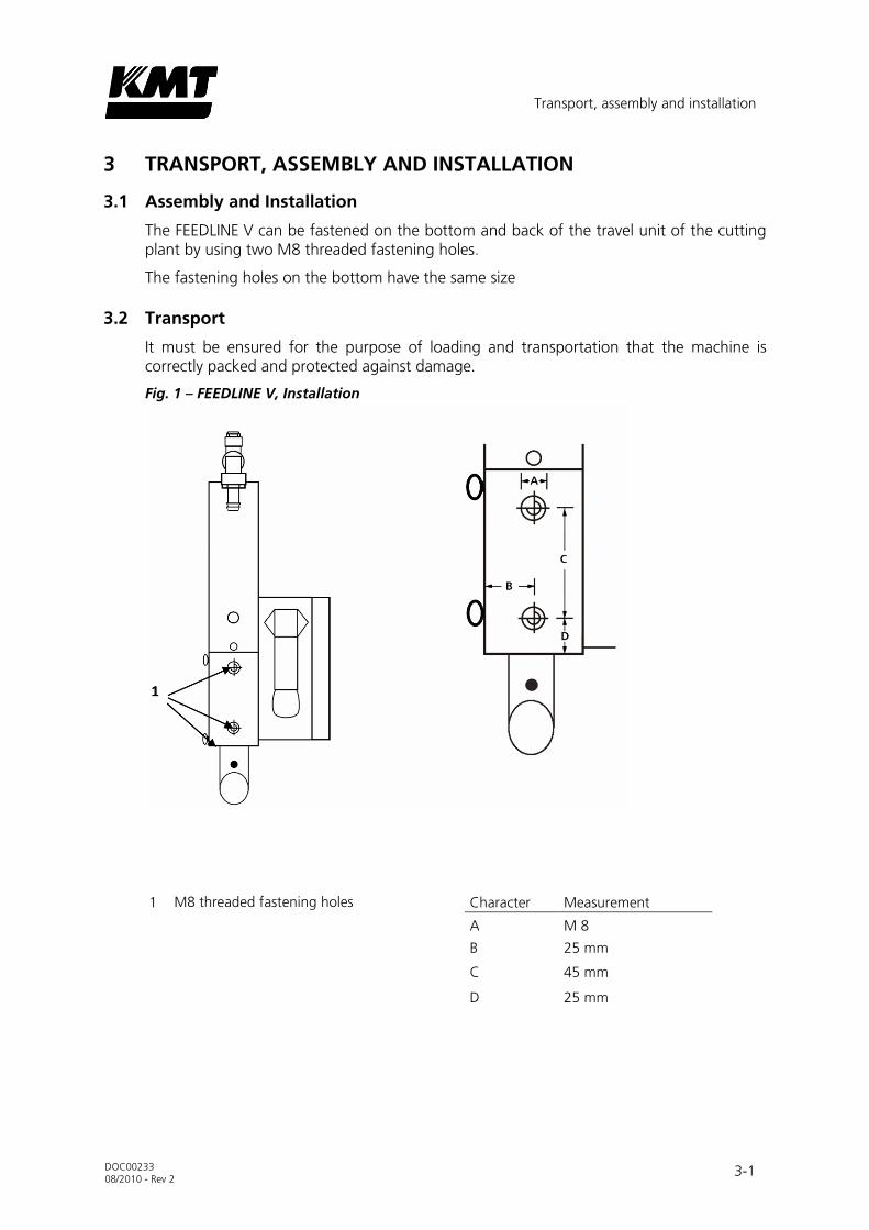
The FEEDLINE V can be fastened on the bottom and back of the travel unit of the cutting plant by using two M8 threaded fastening holes.
The fastening holes on the bottom have the same size
3.2 Transport
It must be ensured for the purpose of loading and transportation that the machine is correctly packed and protected against damage.
Fig. 1 – FEEDLINE V, Installation
1 M8 threaded fastening holes Character Measurement
A M 8
B 25 mm
C 45 mm
D 25 mm


Product description
DOC00233
08/2010 - Rev 2 4-1
4 PRODUCT DESCRIPTION
Fig. 2 – Description of function
1. Abrasive inlet 5. Abrasive vessel filling level viewing window
2. Abrasive inlet air filter 6. Metering wheel housing
3. Abrasive vessel air filter 7. Metering wheel drive motor
4. Abrasive vessel 8. Abrasive outlet
The Venturi effect is used in abrasive cutting to draw with the vacuum generated at the outlet of the water nozzle a defined quantity of abrasive sand through the so-called abrasive hose into the mixing chamber of the abrasive cutter head. This mixing chamber would clog up without the metering device, because the vacuum would draw in the entire available amount of abrasive and convey it to the cutter head. Thus, an accurate, best of all arbitrarily controllable metering device like the FEEDLINE V is indispensable.
The abrasive is conveyed by compressed air into a small 0.8 l intermediate vessel, the abrasive vessel (4). The outlet at the lower end of the abrasive vessel conducts the sand onto the metering wheel the speed of which can be adjusted variably. The grain size of the abrasive as well as the distance between the vessel outlet and metering wheel determine together with the set speed the delivery volume of the metering device.
Product description
DOC00233
08/2010 - Rev 2 4-2
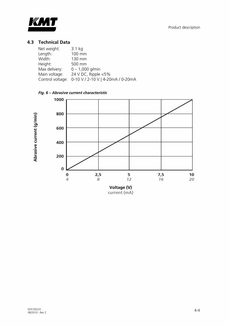
The variable speed control can be adjusted using the generally customary grain size of "80 mesh" along a straight-line characteristic up to a delivery volume of 1,000 g/min. (cf. the diagram on page 4-4)
The variable speed control performs a great service in saving operating costs especially for plant operators who very frequently have to machine different materials in variable thicknesses. Whereas thin materials are cut as a rule with less abrasive, the quantity increases with increasing material thickness. Once these quantity relationships have been filed in the material database of the plant control system, they can be called up automatically and transferred to the electronic control card of the FEEDLINE V. The nominal value can also be set on a potentiometer.
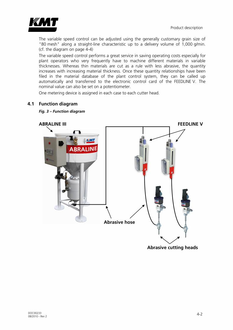
One metering device is assigned in each case to each cutter head.
4.1 Function diagram
Fig. 3 – Function diagram
ABRALINE III FEEDLINE V
Abrasive hose
Abrasive cutting heads
Product description
DOC00233
08/2010 - Rev 2 4-3
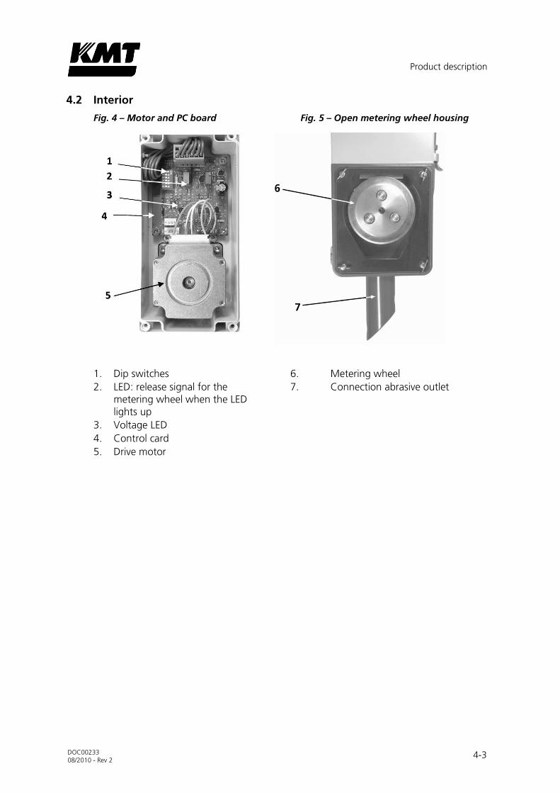
4.2 Interior
Fig. 4 – Motor and PC board Fig. 5 – Open metering wheel housing
1. Dip switches
2. LED: release signal for the metering wheel when the LED lights up
3. Voltage LED
4. Control card
5. Drive motor
6. Metering wheel
7. Connection abrasive outlet
Product description
DOC00233
08/2010 - Rev 2 4-4
4.3 Technical Data
Net weight: 3.1 kg Length: 100 mm Width: 130 mm Height: 500 mm Max delivery: 0 – 1,000 g/min Main voltage: 24 V DC, Ripple <5% Control voltage: 0-10 V / 2-10 V | 4-20mA / 0-20mA
Fig. 6 – Abrasive current characteristic
Voltage (V) current (mA)
Ab
rasi
ve c
urr
en
t (g
/min
)

Commissioning
DOC00233
08/2010 - Rev 2 5-1
5 COMMISSIONING
Fig. 7 – Commissioning
1 Abrasive feeding 3 Outlet pipe
2 Intermediate vessel 4 Harting connector
Before connecting the FEEDLINE V, check it for transport damage which could impair its operating ability.
The abrasive feed (1) of the FEEDLINE V is located on the upper cap. (1/2" hose connection)
Connect the Harting plug (4) to your plant supply (24 V direct current). (cf. Chapter 9, Spare Parts/Electrical Circuit Diagram)
Connect the abrasive hose of the abrasive cutter head to the outlet pipe (3) of the FEEDLINE V.
Fill the intermediate vessel (2) with abrasive.
Select the configuration of the dip switches corresponding to your control system. (cf. Chapter 9, Spare Parts/Electrical Circuit Diagram)
The system is now ready for operation and can be switched on by the release signal of your CNC control.
5.1 Shut-down of the system
Deactivate the system by setting the switch to its "Off" position after completion of work or for elimination of any faults which may have occurred.


Servicing
DOC00233
08/2010 - Rev 2 6-1
6 SERVICING
Servicing and maintenance work is restricted essentially to visual checks.
Fig. 8 – Servicing
1 Viewing window
2 Filter
3 Metering wheel housing
Clean the viewing window (1)
If necessary clean or replace the filter (2)
Clean the housing (3) around the delivery wheel and remove any sand

Trouble-shooting
DOC00233
08/2010 - Rev 2 7-1
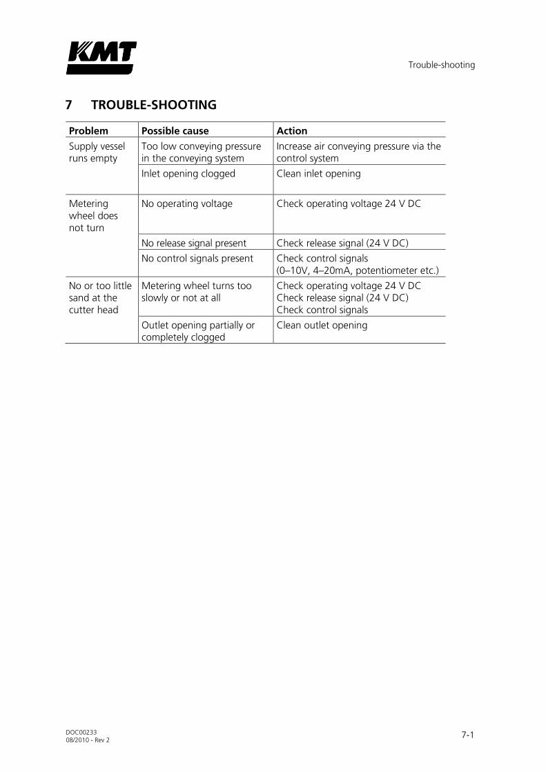
7 TROUBLE-SHOOTING
Problem Possible cause Action
Supply vessel runs empty
Too low conveying pressure in the conveying system
Increase air conveying pressure via the control system
Inlet opening clogged Clean inlet opening
Metering wheel does not turn
No operating voltage Check operating voltage 24 V DC
No release signal present Check release signal (24 V DC)
No control signals present Check control signals (0–10V, 4–20mA, potentiometer etc.)
No or too little sand at the cutter head
Metering wheel turns too slowly or not at all
Check operating voltage 24 V DC Check release signal (24 V DC) Check control signals
Outlet opening partially or completely clogged
Clean outlet opening

Customer and spare parts service
DOC00233
08/2010 - Rev 2 8-1
8 CUSTOMER AND SPARE PARTS SERVICE
8.1 Customer Service
Please contact our customer service department for technical questions.
KMT GmbH KMT Waterjet Systems Waterjet Cutting Technology
Auf der Laukert 11 61231 Bad Nauheim, Germany
Phone: +49-6032-997-117 Fax: +49-6032-997-270
E-mail: [email protected] www.kmt-waterjet.com
8.2 Spare Parts Service
KMT Waterjet maintains a spare-parts department with a comprehensive range stocked; the department's staff is also well trained. Immediate delivery is possible in emergencies.
Contact the KMT Waterjet Service department if you need spare parts.
KMT GmbH KMT Waterjet Systems Waterjet Cutting Technology
Auf der Laukert 11 61231 Bad Nauheim, Germany
Phone: +49-6032-997-115 Fax: +49-6032-997-270
E-mail: [email protected] www.kmt-waterjet.com


Spare parts and circuit diagrams
DOC00233
08/2010 - Rev 2 9-1
9 SPARE PARTS AND CIRCUIT DIAGRAMS
9.1 Spare Parts List

Spare parts and circuit diagrams
DOC00233
08/2010 - Rev 2 9-2
DES
CR
IPT
ION
STEPM
OTO
R S
MA
UN
IT
WH
EEL
DO
SE
BO
X S
MA
UN
IT
CO
NTR
OL
UN
IT S
MA
O-R
ING
, 1
-3/1
6"
x3/8
"x3
/32
"
INSER
T P
LUG
FEM
ALE
INSER
T P
LUG
MA
LE
SH
AFT
SEA
L A
6x1
5x4
NB
R
CA
BLE
GLA
ND
V-M
20
SPO
UT H
OU
SIN
G
AN
NEX
HO
USIN
G
SEA
L SID
E C
OV
ER
CO
UN
TERPA
RT P
RESSED
IN
MO
UN
TIN
G S
TU
D W
ING
-HEA
D S
MA
LL
PR
ESSU
RE S
PRIN
G
WA
SH
ER B
LAC
K
SN
AP R
ING
SLO
TTED
SID
E C
OV
ER
FL-
IV V
ER 4
A
INSPEC
TIO
N W
IND
OW
PER
SPEX
18
0 x
40
x 3
,5
CLO
SIN
G P
LUG
VS 1
2 M
S
CO
UPLI
NG
HO
SE 1
/2"
GT 1
21
3
ELB
OW
1/2
" W
E 1
2 M
SV
TEE 1
/2"
T 1
2 M
SV
SO
UN
D A
BSO
RB
ER W
IRE-C
LOTH
SD
D 1
2 E
S
SIL
EN
CER
PLA
STIC
1/2
"
HO
USIN
G A
SSEM
BLY
FL-
V V
ARN
ISH
ED
BE
SC
HR
EIB
UN
G
SC
HR
ITTM
OTO
R S
MA
EIN
HEIT
RO
LLE D
OSIE
RU
NG
GEH
ÄU
SE S
MA
EIN
HEIT
STEU
EREIN
HEIT
SM
A
O-R
ING
, 1
-3/1
6"
x3/8
"x3
/32
"
EIN
SA
TZ S
TEC
KER
WEIB
LIC
H
EIN
SA
TZ S
TEC
KER
MÄ
NN
LIC
H
WELL
EN
DIC
HTR
ING
A 6
x15
x4N
BR
KA
BELV
ER
SC
HR
AU
BU
NG
V-M
20
TÜ
LLEN
GEH
ÄU
SE
AN
BA
UG
EH
ÄU
SE
DIC
HTU
NG
SEIT
EN
DEC
KEL
EIN
PR
ESSG
EG
EN
STÜ
CK
VER
SC
HLU
SSZA
PFE
N F
LÜG
ELK
OPF
KLE
IN
DR
UC
KFE
DER
UN
TER
LEG
SC
HEIB
E S
CH
WA
RZ
SIC
HER
UN
GSRIN
G G
ESC
HLI
TZT
SEIT
EN
DEC
KEL
FL-I
V V
ER
4A
SIC
HTFE
NSTER
PLE
XIG
LAS 1
80
x 4
0 x
3,5
VER
SC
HLU
SSSTO
PFE
N V
S 1
2 M
S
GEW
IND
ETÜ
LLE 1
/2"
GT 1
213
WIN
KEL
1/2
" W
E 1
2 M
SV
T-S
TÜ
CK
1/2
" T
12
MSV
SC
HA
LLD
ÄM
PFE
R D
RA
HTG
EW
EB
E S
DD
12
ES
SC
HA
LLD
ÄM
PFE
R K
UN
STSTO
FF 1
/2"
BA
UG
RU
PPE G
EH
ÄU
SE F
L-V
LA
CK
IERT
ST
ÜC
K/
QT
Y.
1
1
1
1
1
1
1
1
1
1
1
1
4
4
4
4
4
1
1
1
1
1
1
1
1
1
CP
N
80
37
1
20
42
64
44
05
21
18
98
80
37
3
10
19
35
22
20
42
64
86
20
42
64
68
05
21
05
61
20
42
65
27
20
42
64
94
20
42
65
01
05
21
51
72
05
21
04
13
05
21
04
05
05
21
04
29
05
21
04
37
05
21
04
21
05
21
44
87
05
21
07
51
05
21
06
03
05
21
06
34
05
21
06
27
05
21
06
19
05
21
06
11
20
42
63
19
05
21
52
29
No
.
1
2
3
4
5
6
7
8
9
10
11
12
13
14
15
16
17
18
19
20
21
22
23
24
25
26

Spare parts and circuit diagrams
DOC00233
08/2010 - Rev 2 9-3
9.2 Electric circuit diagram
If optional connection is used, GND (6) must be potential-isolated against GND (2)