Embed Size (px)
Citation preview

8/8/2019 FEM Composite
http://slidepdf.com/reader/full/fem-composite 1/11
8/8/2019 FEM Composite
http://slidepdf.com/reader/full/fem-composite 2/11
Figure 1. Double sink and the working principle of deep forming process
Geometric modeling and Meshing
Due to the symmetrical shape of the product, only one haft of the model is simulated. The working
principle of this deep forming process was described in details in [1]. The geometric modeling of the
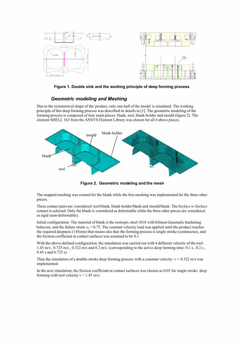
forming process is composed of four main pieces: blank, tool, blank-holder and mould (figure 2). The
element SHELL 163 from the ANSYS Element Library was chosen for all 4 above pieces.
Figure 2. Geometric modeling and the mesh
The mapped meshing was created for the blank while the free meshing was implemented for the three other
pieces.
Three contact pairs are considered: tool/blank, blank-holder/blank and mould/blank. The Surface to Surface
contact is selected. Only the blank is considered as deformable while the three other pieces are consideredas rigid (non-deformable).
Initial configuration: The material of blank is the isotropic steel 1018 with bilinear kinematic hardening
behavior, and the failure strain εf = 0.75. The constant velocity load was applied until the product reaches
the required deepness (145mm) that means also that the forming process is single-stroke (continuous), and
the friction coefficient at contact surfaces was assumed to be 0.1.
With the above-defined configuration, the simulation was carried out with 4 different velocity of the tool:1.45 m/s , 0.725 m/s , 0.322 m/s and 0.2 m/s. (corresponding to the active deep forming time: 0.1 s , 0.2 s ,0.45 s and 0.725 s).
Then the simulation of a double-stroke deep forming process with a constant velocity: v = 0.322 m/s was
implemented.
In the next simulation, the friction coefficient at contact surfaces was chosen as 0.03 for single-stroke deep
forming with tool velocity v = 1.45 m/s.
blank
mould blank-holder
tool
8/8/2019 FEM Composite
http://slidepdf.com/reader/full/fem-composite 3/11
The last simulation was carried out for the transversely anisotropic hardening steel 1010, with the friction
coefficient of 0.1, and by single-stroke forming with tool velocity: v = 0.322 m/s.
Result and Discussion
In figures 3-5 some results of simulation are represented. Some remarks can be deduced as follows:
- In general, the distribution of stress and of strain consists with the theory.
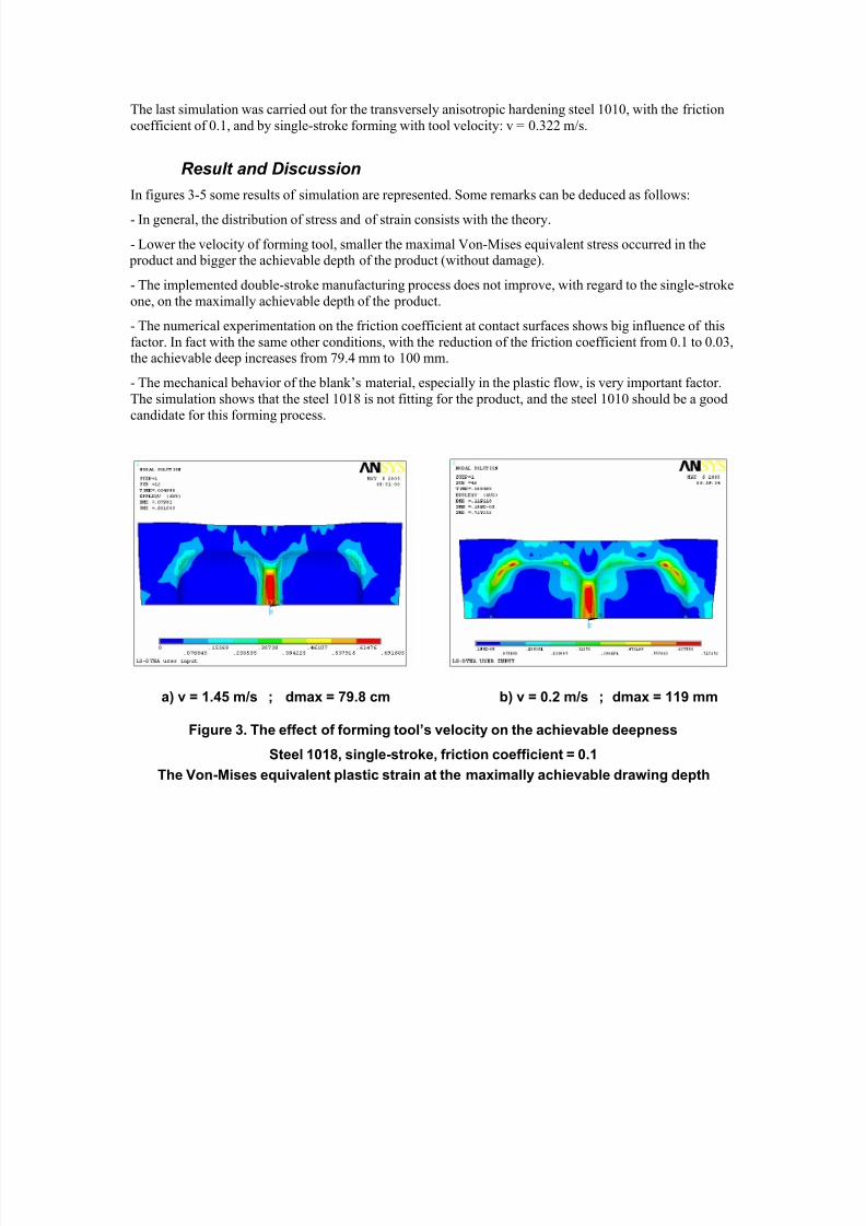
- Lower the velocity of forming tool, smaller the maximal Von-Mises equivalent stress occurred in the product and bigger the achievable depth of the product (without damage).
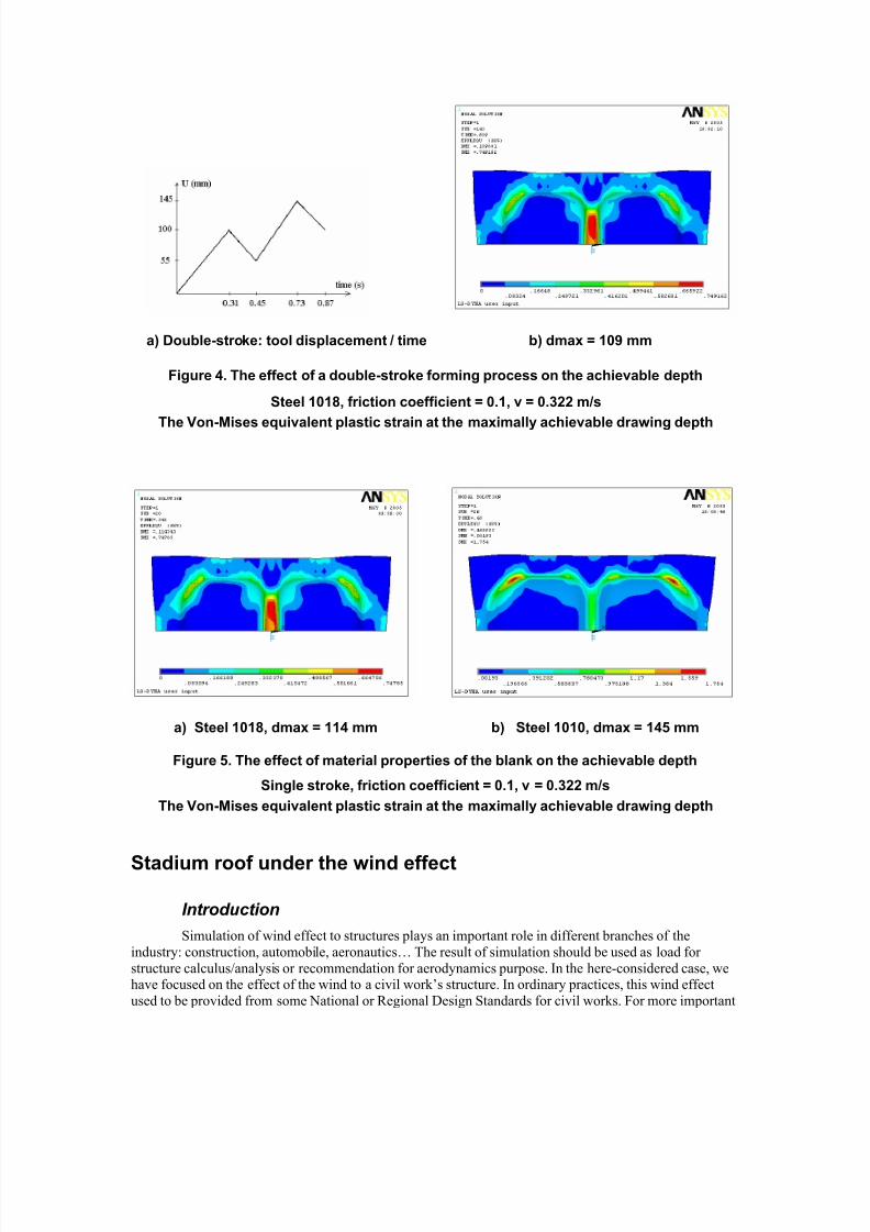
- The implemented double-stroke manufacturing process does not improve, with regard to the single-stroke
one, on the maximally achievable depth of the product.
- The numerical experimentation on the friction coefficient at contact surfaces shows big influence of this
factor. In fact with the same other conditions, with the reduction of the friction coefficient from 0.1 to 0.03,the achievable deep increases from 79.4 mm to 100 mm.
- The mechanical behavior of the blank’s material, especially in the plastic flow, is very important factor.
The simulation shows that the steel 1018 is not fitting for the product, and the steel 1010 should be a good
candidate for this forming process.
a) v = 1.45 m/s ; dmax = 79.8 cm b) v = 0.2 m/s ; dmax = 119 mm
Figure 3. The effect of forming tool’s velocity on the achievable deepness
Steel 1018, single-stroke, friction coefficient = 0.1
The Von-Mises equivalent plastic strain at the maximally achievable drawing depth
8/8/2019 FEM Composite
http://slidepdf.com/reader/full/fem-composite 4/11
a) Double-stroke: tool displacement / time b) dmax = 109 mm
Figure 4. The effect of a double-stroke forming process on the achievable depth
Steel 1018, friction coefficient = 0.1, v = 0.322 m/s
The Von-Mises equivalent plastic strain at the maximally achievable drawing depth
a) Steel 1018, dmax = 114 mm b) Steel 1010, dmax = 145 mm
Figure 5. The effect of material properties of the blank on the achievable depth
Single stroke, friction coefficient = 0.1, v = 0.322 m/s
The Von-Mises equivalent plastic strain at the maximally achievable drawing depth
Stadium roof under the wind effect
Introduction
Simulation of wind effect to structures plays an important role in different branches of the
industry: construction, automobile, aeronautics… The result of simulation should be used as load for
structure calculus/analysis or recommendation for aerodynamics purpose. In the here-considered case, wehave focused on the effect of the wind to a civil work’s structure. In ordinary practices, this wind effect
used to be provided from some National or Regional Design Standards for civil works. For more important
8/8/2019 FEM Composite
http://slidepdf.com/reader/full/fem-composite 5/11
civil works, the physic model of the civil work (not 100 times smaller in dimension than its real structure in
order to achieve the required precision of simulation) must be created. This reduced model is then put in a
wind tunnel for experimentation; with the measured values provided by the wind tunnel’s measuring
equipment, the estimation of the wind effect on the real structure should be obtained. The later solution is
always time-consuming and very expensive; the cost of this physical modeling experimentation increasesquickly with the dimension and the complexity degree of the real structure and will become not-feasible at
all in some cases. With the rapid development of simulating CAE software recently, this problem should be
solved more and more efficiently nowadays. The example in this section will illustrate the powerfulness of the ANSYS/CFX software in the simulating of the wind effect on a stadium roof.
Geometric modeling and Meshing
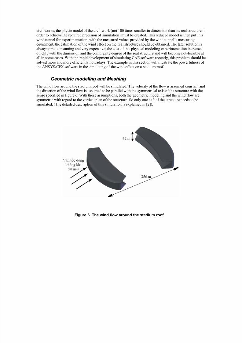
The wind flow around the stadium roof will be simulated. The velocity of the flow is assumed constant andthe direction of the wind flow is assumed to be parallel with the symmetrical axis of the structure with the
sense specified in figure 6. With those assumptions, both the geometric modeling and the wind flow are
symmetric with regard to the vertical plan of the structure. So only one haft of the structure needs to besimulated. (The detailed description of this simulation is explained in [2]).
Figure 6. The wind flow around the stadium roof
8/8/2019 FEM Composite
http://slidepdf.com/reader/full/fem-composite 6/11
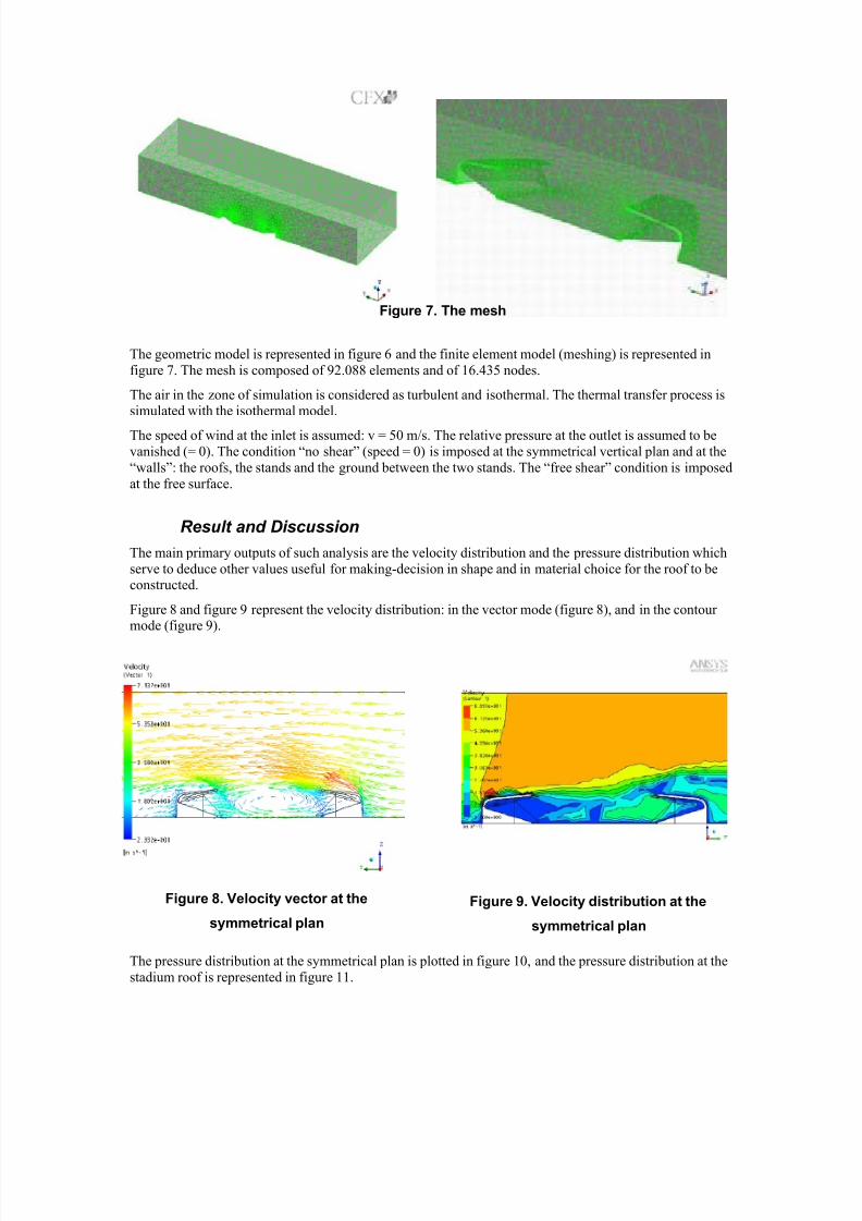
The geometric model is represented in figure 6 and the finite element model (meshing) is represented in
figure 7. The mesh is composed of 92.088 elements and of 16.435 nodes.
The air in the zone of simulation is considered as turbulent and isothermal. The thermal transfer process issimulated with the isothermal model.
The speed of wind at the inlet is assumed: v = 50 m/s. The relative pressure at the outlet is assumed to be
vanished (= 0). The condition “no shear” (speed = 0) is imposed at the symmetrical vertical plan and at the
“walls”: the roofs, the stands and the ground between the two stands. The “free shear” condition is imposed
at the free surface.
Result and Discussion
The main primary outputs of such analysis are the velocity distribution and the pressure distribution which
serve to deduce other values useful for making-decision in shape and in material choice for the roof to beconstructed.
Figure 8 and figure 9 represent the velocity distribution: in the vector mode (figure 8), and in the contour mode (figure 9).
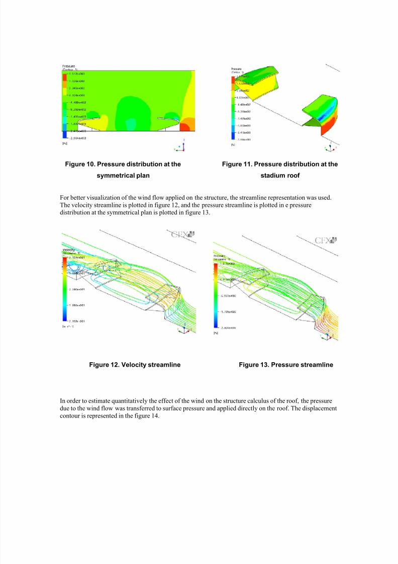
The pressure distribution at the symmetrical plan is plotted in figure 10, and the pressure distribution at the
stadium roof is represented in figure 11.
Figure 8. Velocity vector at the
symmetrical plan
Figure 9. Velocity distribution at the
symmetrical plan
Figure 7. The mesh
8/8/2019 FEM Composite
http://slidepdf.com/reader/full/fem-composite 7/11
For better visualization of the wind flow applied on the structure, the streamline representation was used.The velocity streamline is plotted in figure 12, and the pressure streamline is plotted in e pressuredistribution at the symmetrical plan is plotted in figure 13.
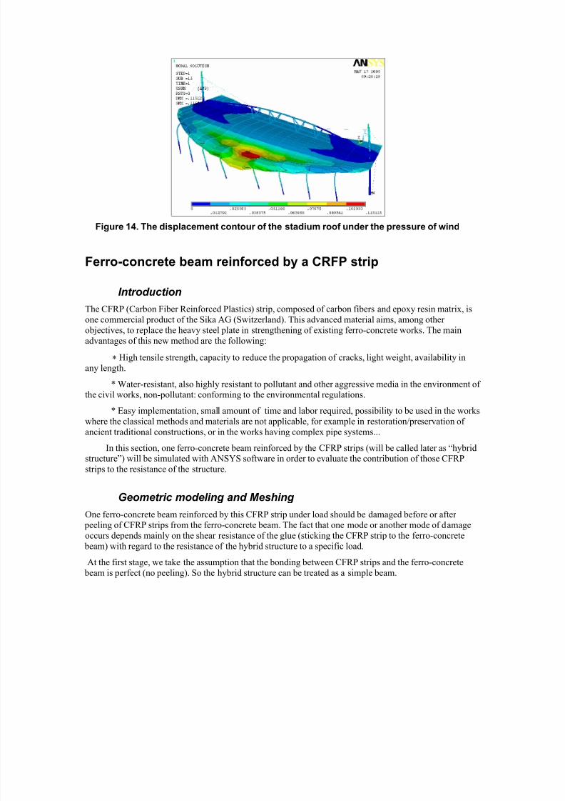
In order to estimate quantitatively the effect of the wind on the structure calculus of the roof, the pressure
due to the wind flow was transferred to surface pressure and applied directly on the roof. The displacement
contour is represented in the figure 14.
Figure 10. Pressure distribution at the
symmetrical plan
Figure 11. Pressure distribution at the
stadium roof
Figure 12. Velocity streamline Figure 13. Pressure streamline
8/8/2019 FEM Composite
http://slidepdf.com/reader/full/fem-composite 8/11
Ferro-concrete beam reinforced by a CRFP strip
Introduction
The CFRP (Carbon Fiber Reinforced Plastics) strip, composed of carbon fibers and epoxy resin matrix, is
one commercial product of the Sika AG (Switzerland). This advanced material aims, among other
objectives, to replace the heavy steel plate in strengthening of existing ferro-concrete works. The main
advantages of this new method are the following:
∗ High tensile strength, capacity to reduce the propagation of cracks, light weight, availability in
any length.
* Water-resistant, also highly resistant to pollutant and other aggressive media in the environment of the civil works, non-pollutant: conforming to the environmental regulations.
* Easy implementation, small amount of time and labor required, possibility to be used in the works
where the classical methods and materials are not applicable, for example in restoration/preservation of ancient traditional constructions, or in the works having complex pipe systems...
In this section, one ferro-concrete beam reinforced by the CFRP strips (will be called later as “hybridstructure”) will be simulated with ANSYS software in order to evaluate the contribution of those CFRP
strips to the resistance of the structure.
Geometric modeling and Meshing
One ferro-concrete beam reinforced by this CFRP strip under load should be damaged before or after peeling of CFRP strips from the ferro-concrete beam. The fact that one mode or another mode of damage
occurs depends mainly on the shear resistance of the glue (sticking the CFRP strip to the ferro-concrete
beam) with regard to the resistance of the hybrid structure to a specific load.
At the first stage, we take the assumption that the bonding between CFRP strips and the ferro-concrete beam is perfect (no peeling). So the hybrid structure can be treated as a simple beam.
Figure 14. The displacement contour of the stadium roof under the pressure of wind

8/8/2019 FEM Composite
http://slidepdf.com/reader/full/fem-composite 9/11
Figure 15. Geometric modeling Figure 16. The mesh
The SOLID65 element is chosen for the concrete, the LINK10 element is chosen for the steel bars in the
ferro-concrete, and the SHELL99 element is chosen for the CFRP strip.
The material properties of components are assumed as:
Steel: isotropic bilinear kinematic hardening with ρ = 7800 kg/m3; E = 200 GPa ; ν = 0.3
Concrete: ρ = 2,500 kg/m3 ; E = 25.787 GPa ; ν = 0.2 ; strength : σTS :1.572 MPa ; σcomp : 20 MPa
CFRP: Transversal isotropic with homogenized values [3] : Ex = 60 GPa ; Ey = Ez = 4.826 GPa ; νxy = νxz
= 0.216 ; νyz = 0.3 ; Gxy = Gxz = 3.266 GPa ; Gyz = 1.862 GPa ; ρ = 1,800 kg/m3 .
The beam is posed in two simple supports (100 mm from its ends). Two concentrated loads of 1,6 KN eachare applied on the beam at the distance of 1,900 mm from its ends.
Figure 17. Load and support
Result and Discussion
8/8/2019 FEM Composite
http://slidepdf.com/reader/full/fem-composite 10/11
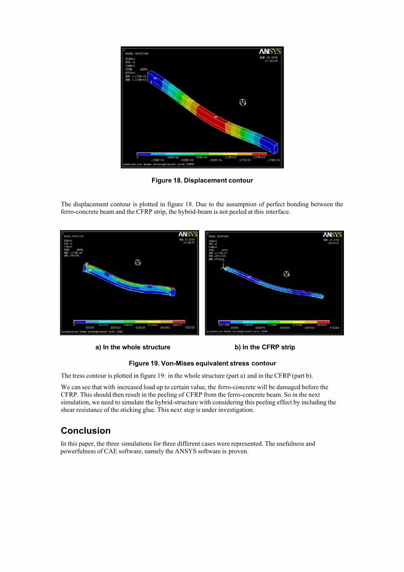
Figure 18. Displacement contour
The displacement contour is plotted in figure 18. Due to the assumption of perfect bonding between theferro-concrete beam and the CFRP strip, the hybrid-beam is not peeled at this interface.
a) In the whole structure b) In the CFRP strip
Figure 19. Von-Mises equivalent stress contour
The tress contour is plotted in figure 19: in the whole structure (part a) and in the CFRP (part b).
We can see that with increased load up to certain value, the ferro-concrete will be damaged before the
CFRP. This should then result in the peeling of CFRP from the ferro-concrete beam. So in the next
simulation, we need to simulate the hybrid-structure with considering this peeling effect by including theshear resistance of the sticking glue. This next step is under investigation.
Conclusion
In this paper, the three simulations for three different cases were represented. The usefulness and
powerfulness of CAE software, namely the ANSYS software is proven.

8/8/2019 FEM Composite
http://slidepdf.com/reader/full/fem-composite 11/11
Acknowledgement
This research is accomplished under the sponsorship of the VLIR-HUT Institutional University
Cooperation Program.
References
[1] Nguyen Viet Hung, Hoang Vinh Sinh, Thai The Hung, Luu Chi Hieu, “Numerical simulation of deep
drawing process for a double sink by using Ansys/LS-Dyna software”, Proceedings of the AUN/SEED-
Net 6th Field-wise Seminar on Manufacturing Engineering, Thailand, 10/2005.
[2] Bui Tran Trung, Nguyen Viet Hung, Bui Hai Le, “Simulation of wind effect to the structures”, Journal
of Science & Technology, vol. 55, in printing , Hanoi, 2006.
[3] Kachlakev, D.I. “Finite Element Analysis of a Historic Bridge Strengthened with FRP Laminates”, paper 003, Third International Conference on Composites in Infrastructure, San Francisco, California,
June 10-12, 2002.