Embed Size (px)
Citation preview

EARTHQUAKE ENGINEERING PRACTICE
Modeling Triple Friction PendulumBearings for Response-History Analysis
Daniel M. Fenz,a)S.M.EERI, and Michael C. Constantinou,b)
M.EERI
There are currently no applicable hysteresis rules or nonlinear elementsavailable in structural analysis software that can be used to exactly model tripleFriction Pendulum bearings for response-history analysis. Series modelscomposed of existing nonlinear elements are proposed since they can beimmediately implemented in currently available analysis software. However,the behavior of the triple Friction Pendulum bearing is not exactly that of aseries arrangement of single concave Friction Pendulum bearings—though it issimilar. This paper describes how to modify the input parameters of the seriesmodel in order to precisely retrace the true force-displacement behaviorexhibited by this device. Recommendations are made for modeling inSAP2000 and are illustrated through analysis of a simple seismically isolatedstructure. The results are confirmed by (a) verifying the force-displacementbehavior through comparison with experimental data and (b) verifying theanalysis through comparison to the results obtained by direct numericalintegration of the equations of motion. �DOI: 10.1193/1.2982531�
INTRODUCTION
When configured properly the triple Friction Pendulum (FP) bearing exhibits desir-able changes in stiffness and damping with increasing amplitude of displacement. Theinternal construction of this device is shown in Figure 1. Previous work (Fenz and Con-stantinou 2008a, 2008b) has demonstrated that the transitions in stiffness and dampingresult from the various combinations of sliding that occur on the multiple concave sur-faces. The behavior and equations governing the force-displacement relationship in eachstage are summarized in Table 1, however for a detailed treatment of the theory and itsexperimental verification the reader is referred to the aforementioned papers. The multi-phase sliding results in a distinct force-displacement relationship that is inherently morecomplex than any exhibited by currently used seismic isolation devices. Consequently, intheir present form models used to describe the behavior of seismic isolators for nonlin-ear response-history analysis are not applicable as they do not capture the multiplechanges in stiffness and damping inherent in the behavior of the triple FP. Two ap-proaches can be taken to model the behavior of this new device: develop and implementa new hysteresis rule to trace the overall behavior, or combine existing nonlinear ele-
a) Ph.D. Candidate, Department of Civil, Structural and Environmental Engineering, University at Buffalo,Buffalo, NY
b)
Professor, Department of Civil, Structural and Environmental Engineering, University at Buffalo, Buffalo, NY1011Earthquake Spectra, Volume 24, No. 4, pages 1011–1028, November 2008; © 2008, Earthquake Engineering Research Institute
1012 D. M. FENZ AND M. C. CONSTANTINOU
ments in such a way that the overall behavior is captured. This paper focuses on the latterapproach and discusses how to model the triple FP using an assembly of gap elementsand single concave FP elements connected in series.
Series models are favored due to their feasibility of implementation in currentlyavailable structural analysis programs. Software such as SAP2000 (Computers andStructures, Inc. 2007) already has nonlinear elements which model the rigid-linear be-havior of traditional FP bearings. However, one behavioral phenomenon in particularprecludes exact modeling of the triple FP bearing as three single FP bearings connectedin series: simultaneous sliding cannot occur at both interfaces of the internal slide plate(surfaces 1 and 2 for example, with reference to Figure 1). This was observed in experi-mental testing and is also predicted analytically (Fenz and Constantinou 2008a, 2008b).Sliding on the inner spherical recess of the slide plate occurs in the initial stage of mo-tion, then stops when sliding begins at the outer sliding interface, and subsequently startsagain when the slide plate contacts the displacement restrainer. Series models do not ex-hibit this start-stop-start behavior.
Although the series model cannot reproduce the complex sliding behavior of all theinternal parts, this paper describes how to capture the overall behavior of the bearingexactly through appropriate modification of the model’s input parameters. That is, thehorizontal force-total displacement relationship for the assembly of elements will be cor-rect, though the relative displacement response of the individual FP elements will notcorrespond exactly to the actual internal sliding behavior. Admittedly, this approach maybe less computationally efficient than a device-specific hysteresis rule; however, thebenefit is that it can be immediately implemented using currently available analysissoftware.
Figure 1. Cross section of the triple FP bearing labeled with parameters that dictate behavior.Ri is the radius of curvature of surface i, hi is the radial distance between the pivot point andsurface i and µi is the coefficient of friction at the sliding interface.

Table 1. Summary of triple FP bearing’s sliding regimes (nomenclature refers to Figure 1)
elationship
�1 3 3effR� ��
3effR
�1 3eff effR�
� �3 4 4 3
4
eff f eff effR F R R� �
� �4 14 1 2 4
4 1eff eff
eff eff
d d R RR R
� � �� � � � � �� � � � �� � � �� � � � �� �
� �� �4 1 1 4eff effR R�� � �� ����
� �1 2 2effR� �� , (5) � �3 4 3 3effd R� � ��
MO
DE
LIN
GT
RIP
LE
FR
ICT
ION
PE
ND
UL
UM
BE
AR
ING
SF
OR
RE
SP
ON
SE
-HIS
TO
RYA
NA
LYS
IS1013
Regime Description Force-Displacement R2 2 3 3
2 3 2 3
f eff f eff
eff eff eff eff
F R F RWF uR R R R
�� �
� �
ISliding on surfaces 2and 3 only Valid
until: 1 1fF F W� � � , � � �1 2 2effu u R�� � � �� �
� �1 1 2 2 2 3
1 3 1 3
f eff eff f eff f
eff eff eff eff
F R R F R FWF uR R R R
� � �� �
� �
IIMotion stops on surface2; Sliding on surfaces 1and 3 Valid
until: 4 4fF F W� � � , � ��4 1u u u R�� �� � � � ��
� �1 1 2 2 2 3
1 4 1
f eff eff f eff f
eff eff eff eff
F R R F R FWF uR R R R
� � �� �
� �
IIIMotion is stopped onsurfaces 2 and 3; Slidingon surfaces 1 and 4 Valid
until:
� �1 1 12 4 1
dr feff eff eff
W WF u u d FR R R
� � � ��
IV Slider contacts restraineron surface 1; Motionremains stopped onsurface 3; Sliding onsurface 2 and 4
Validuntil: 4 4 4
4dr f
eff
WF F d FR
� � � , 4 1dr dru u u� � �
VSlider bears on restrainerof surface 1 and 4;Sliding on surfaces 2and 3
1 1 11
dr feff
WF F d FR
� � � , 41 1
11 eff
dreff
Ru u u d
R��
� � � ���
�
Assumptions: (1) 3241 effeffeffeff RRRR ���� , (2) 2 3 1 4� � � � � � � , (3) � �1 4 1 1effd R� � �� , (4), 2d �
1014 D. M. FENZ AND M. C. CONSTANTINOU
SERIES MODEL OF THE TRIPLE FP BEARING
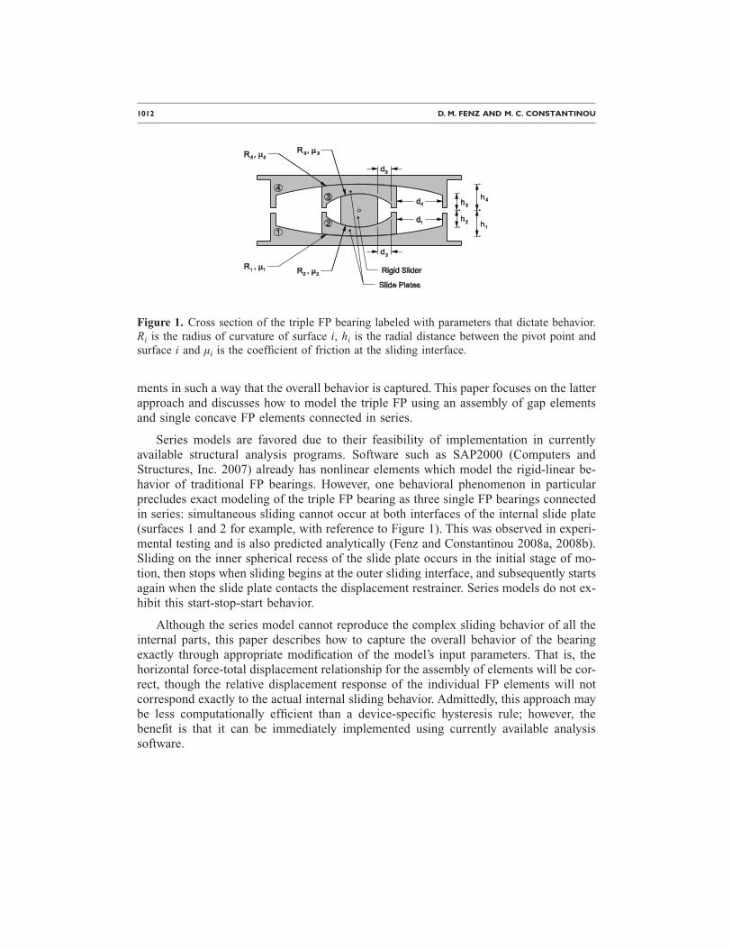
Figure 2 shows a schematic of three single FP elements connected in series. The in-dividual elements are constrained to have the same force, but the relative displacementsof each are independent. Each single FP element consists of a parallel arrangement of(a) a linear elastic spring element representing the restoring force provided by the cur-vature of the spherical dish, (b) a rigid plastic friction element with velocity dependence,and (c) a gap element to account for the finite displacement capacity of each sliding sur-
face. For element i, the stiffness of the spring is given by 1/ Reff i where Reff i is the ef-fective radius of curvature, the velocity dependent coefficient of friction is µi and the
displacement at which the gap element engages is di. In the actual bearing, the effectiveradius of curvature, Reff i, is equal to Ri−hi, where Ri is the radius of curvature of the ith
spherical surface and hi is the radial distance between the ith spherical surface and thepivot point of the articulated slider. Here, overbar notation is used to denote parametersand responses associated with the series model and standard notation is used to denoteparameters and responses associated with the true behavior of the triple FP bearing.
Examining the series model, displacement of element i initiates when the applied
horizontal force F exceeds the friction force, Ffi= µiW, where W is the vertical load sup-ported by the bearing. Motion of element i stops when the relative displacement on the
ith surface becomes equal to the displacement capacity di. This occurs at an applied hori-zontal force of
Fdri =W
Reff i
di + Ffi �1�
The overall stiffness is inversely proportional to the sum of the effective radii of cur-vature of the surfaces upon which sliding is occurring. Once sliding starts on a givensurface, it does not stop until motion reverses direction or the displacement capacity ofthis surface is achieved. The resulting hysteretic behavior obtained by considering threesingle FP elements in series is shown in Figure 3. To construct this loop, it has been
assumed that Ff1� Ff2� Ff3� Fdr2� Fdr3. The shape of this loop is identical to the ac-tual force-total displacement relationship exhibited by triple FP bearings (Fenz and Con-
Figure 2. Three single FP elements in series used to model the behavior of the triple FPbearing.

MODELING TRIPLE FRICTION PENDULUM BEARINGS FOR RESPONSE-HISTORY ANALYSIS 1015
stantinou 2008a, 2008b). Therefore, the approach taken will be to match each branch ofthe loop of Figure 3 to the actual behavior through appropriate modification of the inputparameters to the series model.
INPUT PARAMETERS TO THE SERIES MODEL
The modifications made to the input parameters of the series model are calculatedassuming that three single FP elements are used to represent a triple FP bearing in themost general or fully adaptive configuration. Referring to Figure 1, this means that (a)Reff 2=Reff 3�Reff 1=Reff 4, (b) µ2=µ3�µ1�µ4, (c) d2� �µ1−µ2�Reff 2 and d3� �µ4
−µ3�Reff 3 so that Ff1�Fdr2 and Ff4�Fdr3 and (d) Ff4�Fdr1. The behavior of less adap-tive configurations, such as the common case in which µ2=µ3�µ1=µ4, can also be mod-eled within this framework simply by specifying the appropriate friction coefficients.
In the proposed series modeling scheme, the first FP element represents the com-bined behavior of inner surfaces 2 and 3, the second element represents the behavior ofouter surface 1 and the third represents outer surface 4. Since there is no adjustmentmade to the vertical load supported by the bearings, to ensure that sliding initiates cor-rectly for each element there are no modifications made to the coefficients of friction.That is
µ1 = µ2 = µ3 �2a�
µ2 = µ1 �2b�
µ3 = µ4 �2c�
Total Displacement
0
HorizontalForce
WReff1
WReff1+Reff3
WReff1+Reff2+Reff3
WReff1+Reff2
WReff1
2Ff1
0
WReff1
WReff1+Reff2
WReff1+Reff2+Reff3
Ff1
Ff2
Ff3
Fdr2
Fdr3
Fdr2 - 2Ff2
Fdr3 - 2Ff3
Figure 3. Force-displacement behavior of three single FP elements connected in series.
1016 D. M. FENZ AND M. C. CONSTANTINOU
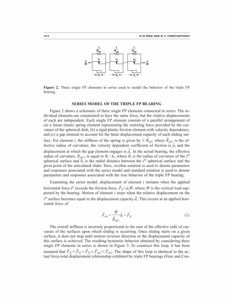
For Ff2=Ff3�F�Ff1, the true behavior is sliding occurring only on surfaces 2 and3. In the series model, there is sliding occurring only for element 1. Therefore, to prop-erly capture the stiffness during this sliding regime, it is necessary that
Reff 1 = Reff 2 + Reff 3 �3�
For Ff1�F�Ff4, sliding occurs on surfaces 1 and 3 only in the actual bearing—motionstops on surface 2 the instant it starts on surface 1. However, the series model cannotcapture the stoppage of motion for one element once it has begun for another. The ef-fective radius of the second FP element in the series model is obtained by equating thestiffness given by the series model with the actual stiffness exhibited by the bearing:
W
Reff 1 + Reff 2
=W
Reff 1 + Reff 3�4�
Combining Equations 3 and 4:
Reff 2 = Reff 1 − Reff 2 �5�
For Ff4�F�Fdr1, the true behavior is sliding on surfaces 1 and 4 only—motion stopson surface 3 the instant it starts on surface 4. The effective radius of the third FP elementin the series model is obtained by again equating the series model stiffness with the ac-tual stiffness exhibited by the bearing:
W
Reff 1 + Reff 2 + Reff 3
=W
Reff 1 + Reff 4�6�
Combining Equations 3, 5, and 6:
Reff 3 = Reff 4 − Reff 3 �7�
To ensure that the onset of stiffening behavior is accurately captured, the force at
which the first gap element engages in the series model, Fdr2, is set equal to the force atwhich the slider contacts the displacement restrainer of surface 1, Fdr1:
d2
Reff 2
+ µ2 =d1
Reff 1+ µ1 �8�
Using Equations 2b and 5,
d2 =Reff 1 − Reff 2
Reff 1d1 �9�
Similarly, to ensure that Fdr3=Fdr4, it is necessary that
MODELING TRIPLE FRICTION PENDULUM BEARINGS FOR RESPONSE-HISTORY ANALYSIS 1017
d3 =Reff 4 − Reff 3
Reff 4d4 �10�
For F�Fdr4, sliding occurs only on surfaces 2 and 3 to the maximum displacement. Theseries model gives sliding only for element 1. The stiffness is predicted correctly by theseries model during this sliding regime per Equation 3. If desired to model the total dis-placement capacity of the bearing, the displacement capacity of the first FP element canbe assigned
d1 = �d1 + d2 + d3 + d4� − �d2 + d3� �11�
or it can be left unspecified (infinite displacement capacity). When equating the actualbehavior of the bearing with the behavior given by three elements in series, the stiffnessduring each sliding regime as well as the forces at which transitions in stiffness occurwere enforced to be equal. It follows that the overall displacements at which the transi-tions in stiffness occur must also be equal.
Adjustments are also made to properly capture the velocity dependence of the coef-ficient of friction. At each sliding interface, the coefficient of friction varies with veloc-ity according to the following relationship (Constantinou et al. 1990):
µ = fmax − �fmax − fmin�exp�− a�u�� �12�
where fmax is the coefficient of friction at high velocity, fmin is the coefficient of frictionat very slow velocity, a is a rate parameter that controls the transition between fmax andfmin, and u is the sliding velocity.
The rate parameter a is adjusted to properly model the velocity dependence of thecoefficient of friction on surfaces 1 and 4. The velocity dependence will be properly
modeled on surface 1 of the actual bearing provided that a2u2=a1u1. This is guaranteedby specifying
a2 =Reff 1
Reff 1 − Reff 2a1 �13�
Similarly, for surface 4 of the actual bearing
a3 =Reff 4
Reff 4 − Reff 3a4 �14�
For the first FP element of the series model, the rate parameter can be specified as halfof the average of the rate parameters on surfaces 2 and 3 of the actual bearing because
the actual sliding velocities on surfaces 2 and 3 are half of the relative velocity u1 cal-culated using the series model. Therefore,
1018 D. M. FENZ AND M. C. CONSTANTINOU
a1 =1
2
�a2 + a3�2
�15�
Equation 15 will properly represent the velocity dependence during stages when slidingis occurring only on surfaces 2 and 3 of the actual bearing. Table 2 summarizes the val-ues assigned to the input parameters of the three element series model.
IMPLEMENTATION AND VALIDATION
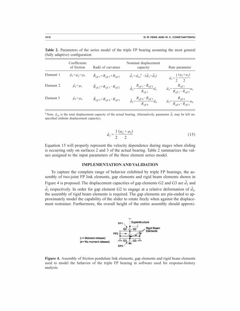
To capture the complete range of behavior exhibited by triple FP bearings, the as-sembly of two-joint FP link elements, gap elements and rigid beam elements shown in
Figure 4 is proposed. The displacement capacities of gap elements G2 and G3 are d2 and
d3 respectively. In order for gap element G2 to engage at a relative deformation of d2,the assembly of rigid beam elements is required. The gap elements are pin-ended to ap-proximately model the capability of the slider to rotate freely when against the displace-ment restrainer. Furthermore, the overall height of the entire assembly should approxi-
Table 2. Parameters of the series model of the triple FP bearing assuming the most general(fully adaptive) configuration
Coefficientsof friction Radii of curvature
Nominal displacementcapacity Rate parameter
Element 1 µ1=µ2=µ3 Reff 1=Reff 2+Reff 3 d1=dtota −�d2+ d3�
a1=1
2
�a2+a3�
2Element 2 µ2=µ1 Reff 2=Reff 1−Reff 2 d2=
Reff 1−Reff 2
Reff 1d1 a2=
Reff 1
Reff 1−Reff 2a1
Element 3 µ3=µ4 Reff 3=Reff 4−Reff 3 d3=Reff 4−Reff 3
Reff 4d4 a3=
Reff 4
Reff 4−Reff 3a4
a Note: dtot is the total displacement capacity of the actual bearing. Alternatively, parameter d1 may be left un-specified (infinite displacement capacity).
Figure 4. Assembly of friction pendulum link elements, gap elements and rigid beam elementsused to model the behavior of the triple FP bearing in software used for response-history
analysis.
MODELING TRIPLE FRICTION PENDULUM BEARINGS FOR RESPONSE-HISTORY ANALYSIS 1019
mately correspond to the height of the actual bearing. Additional guidelines formodeling FP bearings for response-history analysis in SAP2000 are provided in Schellerand Constantinou (2002) and Constantinou et al. (2007) and are generally applicable.
It should be noted that the complete arrangement shown in Figure 4 is needed onlyfor modeling all sliding regimes of the most general (fully adaptive) configuration oftriple FP bearing. In many cases, certain elements can be omitted from the model tomake the analysis more efficient. For example, the gap elements can be omitted in loweramplitude excitations or in cases in which the engineer does not wish to utilize the stiff-ening capability of the device. When this is done however, the actual relative displace-ments must be checked to verify that the displacement restrainers are not contacted.Also, in simpler configurations, such as equal friction on the inner two surfaces alongwith equal friction on the outer two interfaces, the behavior can be properly capturedusing only two FP link elements—the first having friction µ2=µ3 and effective radiusReff 2+Reff 3 and the second having friction µ1=µ4 and effective radius Reff 1+Reff 4
−Reff 2−Reff 3.
The arrangement described in the figure is exact only for horizontal excitation in onedirection (collinear with the gap elements). One may be tempted to include gap elementsin both orthogonal horizontal directions and perform a full three dimensional analysis.However, the results would be flawed because the gap element’s properties in SAP2000are uncoupled; that is, they are independent in each deformational degree of freedom(Computers and Structures, Inc. 2007). Physically, this represents a bearing that issquare in plan. Obviously, the bearing is circular in plan, which means that the gap el-ement must engage when the resultant relative displacement equals the displacement ca-
pacity di. However, a coupled gap element is not currently available in SAP2000. Towork around this, more gap elements can be used in the assembly to approximate a circleusing straight line segments. Though the assembly becomes somewhat complex, the“replicate radial” command in the software can be used to efficiently build the model.Alternatively, a preliminary analysis can be conducted without gap elements to deter-mine the directions in which they would be engaged. The model can subsequently bemodified to include gap elements in these directions.
General purpose finite element software can also be used for the analysis. For ex-ample, ABAQUS (Hibbitt, Karlsson and Sorensen, Inc. 2004) has a cylindrical gap ele-ment, the GAPCYL element, that can be employed for bidirectional analysis. This ele-ment is used to model contact between two rigid tubes of different diameter, where thesmaller tube is located inside the larger tube. Clarke et al. (2005) present a case study inwhich ABAQUS software was used to analyze an offshore oil platform isolated withsingle concave FP bearings.
The force-displacement behavior predicted by the series model was validated bycomparison to experimental data generated from characterization testing of a small-scaletriple FP bearing. The bearings used in the analysis are assumed to have the properties ofa triple FP bearing recently tested at the University at Buffalo (Fenz and Constantinou2008b). The properties of the bearing obtained from characterization testing and the at-tendant properties of the series model are listed in Table 3. Based on this, the various
1020 D. M. FENZ AND M. C. CONSTANTINOU
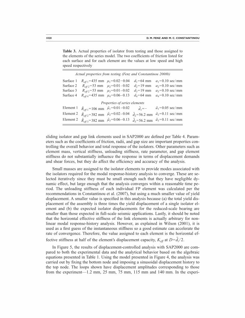
sliding isolator and gap link elements used in SAP2000 are defined per Table 4. Param-eters such as the coefficients of friction, radii, and gap size are important properties con-trolling the overall behavior and total response of the isolators. Other parameters such aselement mass, vertical stiffness, unloading stiffness, rate parameter, and gap elementstiffness do not substantially influence the response in terms of displacement demandsand shear forces, but they do affect the efficiency and accuracy of the analysis.
Small masses are assigned to the isolator elements to provide modes associated withthe isolators required for the modal response-history analysis to converge. These are se-lected iteratively since they must be small enough such that they have negligible dy-namic effect, but large enough that the analysis converges within a reasonable time pe-riod. The unloading stiffness of each individual FP element was calculated per therecommendations in Constantinou et al. (2007), but using a much smaller value of yielddisplacement. A smaller value is specified in this analysis because (a) the total yield dis-placement of the assembly is three times the yield displacement of a single isolator el-ement and (b) the expected isolator displacements for the reduced-scale bearing aresmaller than those expected in full-scale seismic applications. Lastly, it should be notedthat the horizontal effective stiffness of the link elements is actually arbitrary for non-linear modal response-history analysis. However, as explained in Wilson (2001), it isused as a first guess of the instantaneous stiffness so a good estimate can accelerate therate of convergence. Therefore, the value assigned to each element is the horizontal ef-
fective stiffness at half of the element’s displacement capacity, Keff at D= di /2.
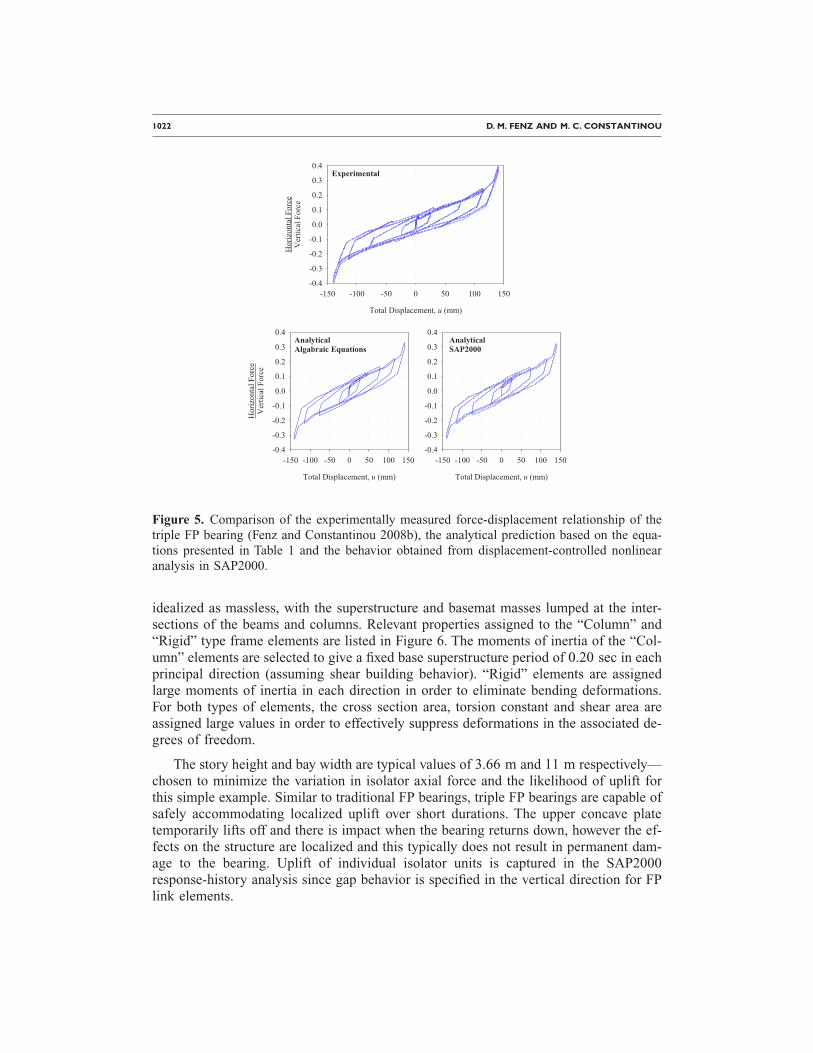
In Figure 5, the results of displacement-controlled analysis with SAP2000 are com-pared to both the experimental data and the analytical behavior based on the algebraicequations presented in Table 1. Using the model presented in Figure 4, the analysis wascarried out by fixing the bottom node and imposing a sinusoidal displacement history tothe top node. The loops shown have displacement amplitudes corresponding to thosefrom the experiment—1.2 mm, 25 mm, 75 mm, 115 mm and 140 mm. In the experi-
Table 3. Actual properties of isolator from testing and those assigned tothe elements of the series model. The two coefficients of friction listed foreach surface and for each element are the values at low speed and highspeed respectively
Actual properties from testing (Fenz and Constantinou 2008b)
Surface 1 Reff 1=435 mm µ1=0.02−0.04 d1=64 mm a1=0.10 sec/mmSurface 2 Reff 2=53 mm µ2=0.01–0.02 d2=19 mm a2=0.10 sec/mmSurface 3 Reff 2=53 mm µ3=0.01–0.02 d3=19 mm a3=0.10 sec/mmSurface 4 Reff 4=435 mm µ4=0.06–0.13 d4=64 mm a4=0.10 sec/mm
Properties of series elementsElement 1 Reff 1=106 mm µ1=0.01–0.02 d1=− a1=0.05 sec/mm
Element 2 Reff 2=382 mm µ2=0.02–0.04 d2=56.2 mm a2=0.11 sec/mm
Element 2 Reff 3=382 mm µ3=0.06–0.13 d3=56.2 mm a3=0.11 sec/mm

MODELING TRIPLE FRICTION PENDULUM BEARINGS FOR RESPONSE-HISTORY ANALYSIS 1021
ment, the frequency of the excitation was very low to minimize velocity dependence ofthe coefficient of friction. Accordingly, single-valued coefficients of friction were speci-fied in the analysis as well. Since the exact values of friction cannot be known before-hand, the friction coefficients specified in the analysis are those measured from each test.As shown in Figure 5, the proposed modeling scheme accurately reproduces both theexperimental results and the results from more simplified analysis for all combinationsof sliding behavior.
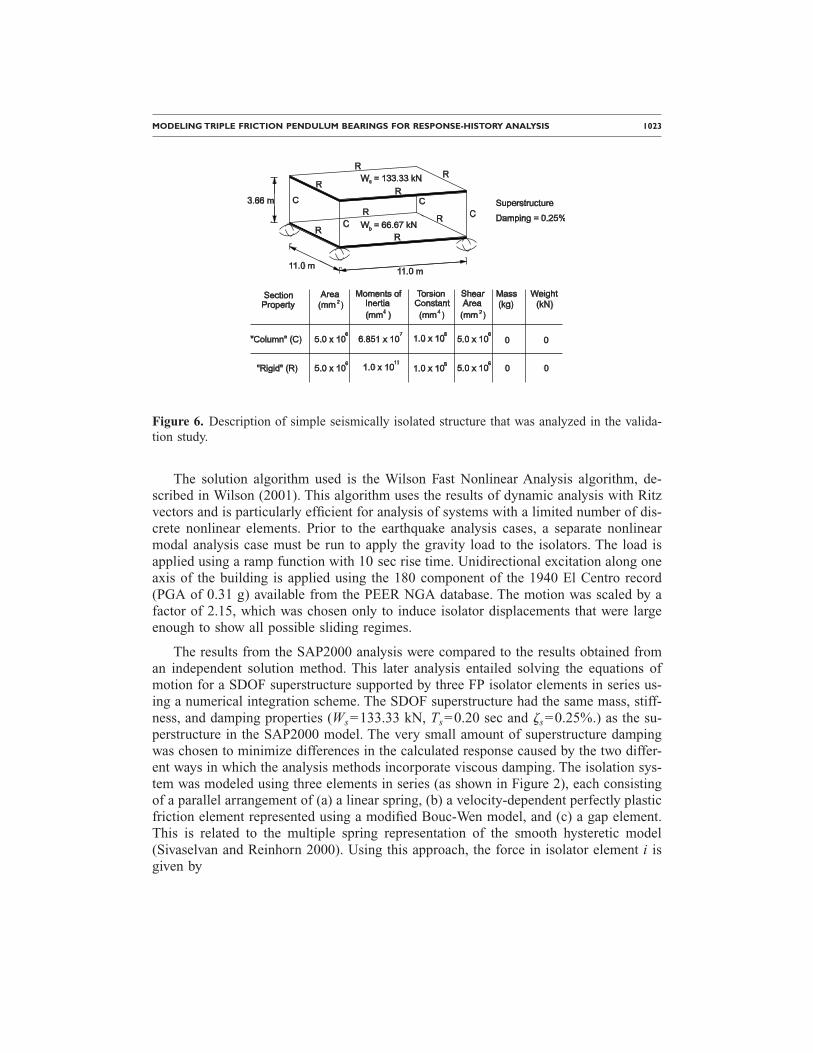
This first analysis case serves to physically validate the force-displacement relation-ship given by the assembly of nonlinear elements with properly modified input param-eters. Next, to verify the basic numerical accuracy of the dynamic response-historyanalysis procedures, a simple single story shear building isolated with triple FP bearingsis analyzed. The isolators are modeled the same way as the previous analysis except nowincorporating the effect of velocity dependence on the coefficients of friction. The ana-lytical model of the superstructure is shown in Figure 6. The total weight is 200 kN,divided two-thirds to the story mass and one-third to the basemat. All frame elements are
Table 4. Properties of sliding isolator and gap link elements used inSAP2000 analysis
Sliding isolator link elementsFP1 FP2 FP3
Mass �kN-sec2 /mm� 5.0�10−7 5.0�10−7 5.0�10−7
Element height (mm) 50 25 50Vertical stiffness (kN/mm) 4,000 8,000 4,000Horizontal effective stiffness (kN/mm) 0.524 0.202 0.362Shear deformation location (mm) 25 12.5 25Yield displacement (mm) 0.01 0.01 0.01Unloading stiffness (kN/mm) 50 100 300Coefficient of friction-slowa 0.01 0.02 0.06Coefficient of friction-fasta 0.02 0.04 0.13Rate parameter (sec/mm) 0.05 0.112 0.112Radius (mm) 106 382 382Rotational stiffness (kN-mm/rad) 3.0�106 3.0�106 3.0�106
Gap link elementsGap2 Gap3
Mass �kN-sec2 /mm� 1.0�10−9 1.0�10−9
Element length (mm) 150 150Effective stiffness (kN/mm) 0.5 0.5Gap size (mm) 56.2 56.2Stiffness after closing (kN/mm) 250 250
a Note: Velocity dependent coefficients of friction are used only for the nonlinearresponse-history analysis. Single valued friction coefficients based on the experimentalresults are used for the displacement controlled analysis.
1022 D. M. FENZ AND M. C. CONSTANTINOU
idealized as massless, with the superstructure and basemat masses lumped at the inter-sections of the beams and columns. Relevant properties assigned to the “Column” and“Rigid” type frame elements are listed in Figure 6. The moments of inertia of the “Col-umn” elements are selected to give a fixed base superstructure period of 0.20 sec in eachprincipal direction (assuming shear building behavior). “Rigid” elements are assignedlarge moments of inertia in each direction in order to eliminate bending deformations.For both types of elements, the cross section area, torsion constant and shear area areassigned large values in order to effectively suppress deformations in the associated de-grees of freedom.
The story height and bay width are typical values of 3.66 m and 11 m respectively—chosen to minimize the variation in isolator axial force and the likelihood of uplift forthis simple example. Similar to traditional FP bearings, triple FP bearings are capable ofsafely accommodating localized uplift over short durations. The upper concave platetemporarily lifts off and there is impact when the bearing returns down, however the ef-fects on the structure are localized and this typically does not result in permanent dam-age to the bearing. Uplift of individual isolator units is captured in the SAP2000response-history analysis since gap behavior is specified in the vertical direction for FPlink elements.
Experimental
Total Displacement, u (mm)
-150 -100 -50 0 50 100 150HorizontalForce
VerticalForce
-0.4
-0.3
-0.2
-0.1
0.0
0.1
0.2
0.3
0.4
AnalyticalAlgabraic Equations
Total Displacement, u (mm)
-150 -100 -50 0 50 100 150
HorizontalForce
VerticalForce
-0.4
-0.3
-0.2
-0.1
0.0
0.1
0.2
0.3
0.4AnalyticalSAP2000
Total Displacement, u (mm)
-150 -100 -50 0 50 100 150-0.4
-0.3
-0.2
-0.1
0.0
0.1
0.2
0.3
0.4
Figure 5. Comparison of the experimentally measured force-displacement relationship of thetriple FP bearing (Fenz and Constantinou 2008b), the analytical prediction based on the equa-tions presented in Table 1 and the behavior obtained from displacement-controlled nonlinearanalysis in SAP2000.
MODELING TRIPLE FRICTION PENDULUM BEARINGS FOR RESPONSE-HISTORY ANALYSIS 1023
The solution algorithm used is the Wilson Fast Nonlinear Analysis algorithm, de-scribed in Wilson (2001). This algorithm uses the results of dynamic analysis with Ritzvectors and is particularly efficient for analysis of systems with a limited number of dis-crete nonlinear elements. Prior to the earthquake analysis cases, a separate nonlinearmodal analysis case must be run to apply the gravity load to the isolators. The load isapplied using a ramp function with 10 sec rise time. Unidirectional excitation along oneaxis of the building is applied using the 180 component of the 1940 El Centro record(PGA of 0.31 g) available from the PEER NGA database. The motion was scaled by afactor of 2.15, which was chosen only to induce isolator displacements that were largeenough to show all possible sliding regimes.
The results from the SAP2000 analysis were compared to the results obtained froman independent solution method. This later analysis entailed solving the equations ofmotion for a SDOF superstructure supported by three FP isolator elements in series us-ing a numerical integration scheme. The SDOF superstructure had the same mass, stiff-ness, and damping properties (Ws=133.33 kN, Ts=0.20 sec and �s=0.25%.) as the su-perstructure in the SAP2000 model. The very small amount of superstructure dampingwas chosen to minimize differences in the calculated response caused by the two differ-ent ways in which the analysis methods incorporate viscous damping. The isolation sys-tem was modeled using three elements in series (as shown in Figure 2), each consistingof a parallel arrangement of (a) a linear spring, (b) a velocity-dependent perfectly plasticfriction element represented using a modified Bouc-Wen model, and (c) a gap element.This is related to the multiple spring representation of the smooth hysteretic model(Sivaselvan and Reinhorn 2000). Using this approach, the force in isolator element i isgiven by
Figure 6. Description of simple seismically isolated structure that was analyzed in the valida-tion study.
1024 D. M. FENZ AND M. C. CONSTANTINOU
Fi =W
Reff iui + µiWZi + kri��ui� − di�sign�ui�H��ui� − di� �16�
where W, Reff i and di have been previously defined, ui is the relative displacement of FPelement i, µi is the coefficient of friction with velocity dependence governed by Equa-tion 12, kri is the stiffness after contacting the displacement restrainer which should beassigned a large value, H denotes the Heaviside function and Zi is a dimensionless hys-teretic variable governed by the differential equation:
dZi
dt=
1
uyi�Ai − �Zi��i��i sign�uiZi� + �i��ui �17�
where uyi is the yield displacement, and Ai, �i, �i and �i are dimensionless quantitiesthat control the shape of the hysteresis loop (uyi=0.01, Ai=1, �i=0.9, �i=2 and �i=1).These are essentially the equations that are used for dynamic analysis of FP bearings inthe 3D-BASIS software platform (Nagarajaiah et al. 1989). The only difference is thelast term of Equation 16, which is the additional restoring force from contacting the dis-placement restrainer.
For the same El Centro 180 excitation used in the SAP2000 analysis, the equationsof motion for three FP elements connected in series and attached to a viscously dampedSDOF superstructure were formulated using a state-space approach and then integratednumerically using the ode15s solver in MATLAB (The MathWorks, Inc. 2005). Theode15s solver is a variable order, multi-step algorithm that is efficient in solving sys-tems of stiff differential equations (Shampine and Reichelt 1997). The system is math-ematically stiff due to the sharp transitions in stiffness that occur for each FP elementupon reversal of motion.
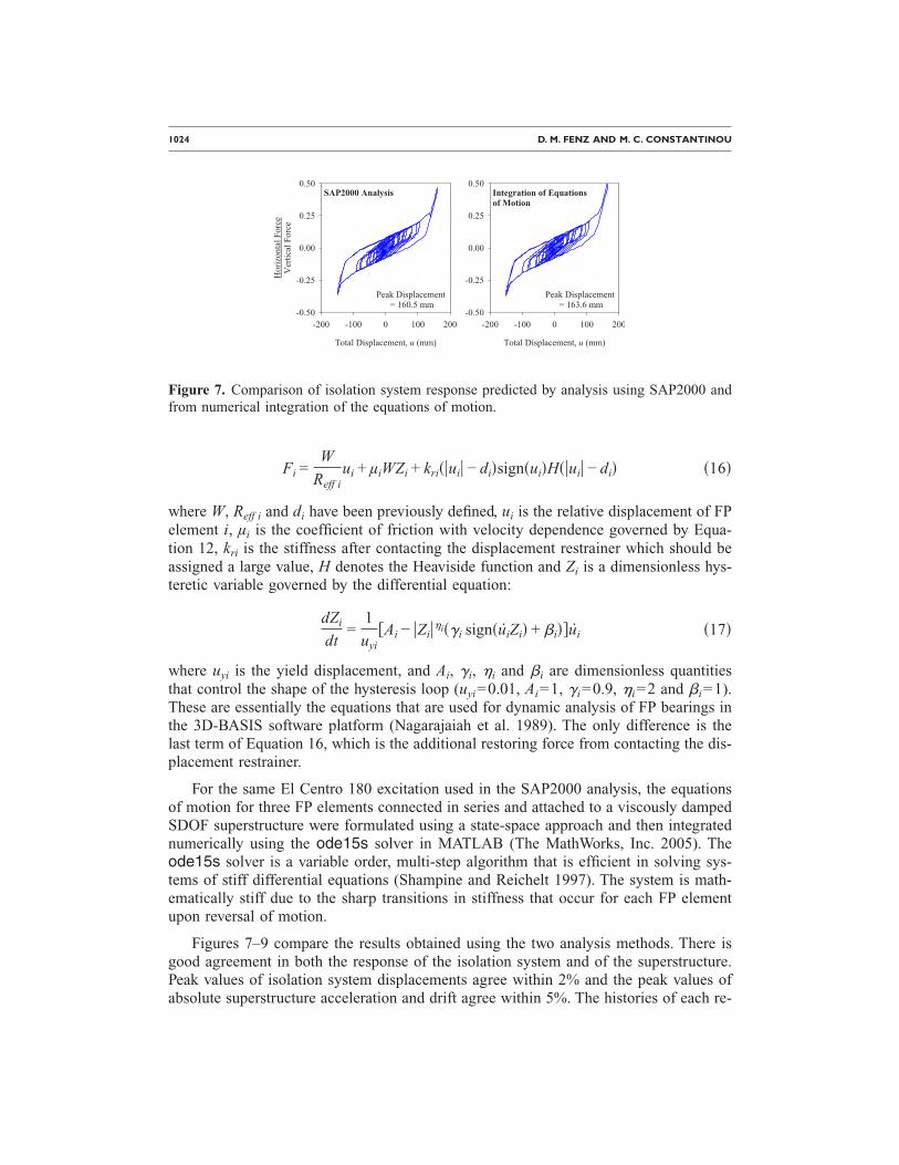
Figures 7–9 compare the results obtained using the two analysis methods. There isgood agreement in both the response of the isolation system and of the superstructure.Peak values of isolation system displacements agree within 2% and the peak values ofabsolute superstructure acceleration and drift agree within 5%. The histories of each re-
SAP2000 Analysis
Total Displacement, u (mm)
-200 -100 0 100 200
HorizontalForce
VerticalForce
-0.50
-0.25
0.00
0.25
0.50Integration of Equationsof Motion
Total Displacement, u (mm)
-200 -100 0 100 200-0.50
-0.25
0.00
0.25
0.50
Peak Displacement= 160.5 mm
Peak Displacement= 163.6 mm
Figure 7. Comparison of isolation system response predicted by analysis using SAP2000 andfrom numerical integration of the equations of motion.

MODELING TRIPLE FRICTION PENDULUM BEARINGS FOR RESPONSE-HISTORY ANALYSIS 1025
sponse quantity also correspond closely to each other. The agreement of the results givenby the two independent formulations and solution methods gives added confidence in thevalidity of this proposed approach. Furthermore, this analysis represents extreme re-sponse of the isolators—in practice it is unlikely that engineers will design into the final
SAP2000 Analysis
0 10 20 30 40
AbsoluteAcceleration(g)
-0.75
-0.50
-0.25
0.00
0.25
0.50
0.75
Integration of Equationsof Motion
Time (sec)
0 10 20 30 40
AbsoluteAcceleration(g)
-0.75
-0.50
-0.25
0.00
0.25
0.50
0.75
Peak Value = -0.613g
Peak Value = -0.644g
Figure 8. Comparison of the histories of superstructure absolute acceleration response deter-mined from analysis using SAP2000 and from numerical integration of the equations ofmotion.
SAP2000 Analysis
0 10 20 30 40
SuperstructureDrift(mm)
-8
-4
0
4
8
Integration of Equationsof Motion
Time (sec)
0 10 20 30 40
SuperstructureDrift(mm)
-8
-4
0
4
8
Peak Value = 6.11 mm
Peak Value = 6.40 mm
Figure 9. Comparison of the histories of superstructure drift determined from analysis using
SAP2000 and from numerical integration of the equations of motion.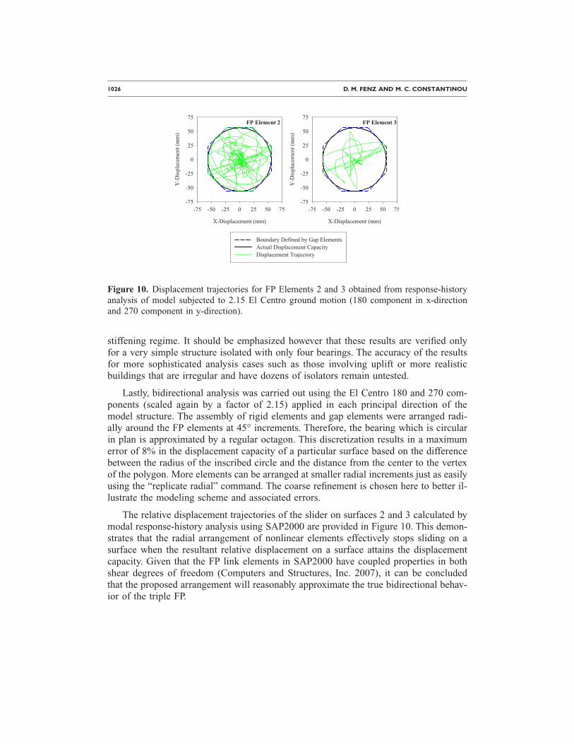
1026 D. M. FENZ AND M. C. CONSTANTINOU
stiffening regime. It should be emphasized however that these results are verified onlyfor a very simple structure isolated with only four bearings. The accuracy of the resultsfor more sophisticated analysis cases such as those involving uplift or more realisticbuildings that are irregular and have dozens of isolators remain untested.
Lastly, bidirectional analysis was carried out using the El Centro 180 and 270 com-ponents (scaled again by a factor of 2.15) applied in each principal direction of themodel structure. The assembly of rigid elements and gap elements were arranged radi-ally around the FP elements at 45° increments. Therefore, the bearing which is circularin plan is approximated by a regular octagon. This discretization results in a maximumerror of 8% in the displacement capacity of a particular surface based on the differencebetween the radius of the inscribed circle and the distance from the center to the vertexof the polygon. More elements can be arranged at smaller radial increments just as easilyusing the “replicate radial” command. The coarse refinement is chosen here to better il-lustrate the modeling scheme and associated errors.
The relative displacement trajectories of the slider on surfaces 2 and 3 calculated bymodal response-history analysis using SAP2000 are provided in Figure 10. This demon-strates that the radial arrangement of nonlinear elements effectively stops sliding on asurface when the resultant relative displacement on a surface attains the displacementcapacity. Given that the FP link elements in SAP2000 have coupled properties in bothshear degrees of freedom (Computers and Structures, Inc. 2007), it can be concludedthat the proposed arrangement will reasonably approximate the true bidirectional behav-ior of the triple FP.
FP Element 2
X-Displacement (mm)
-75 -50 -25 0 25 50 75
Y-Displacement(mm)
-75
-50
-25
0
25
50
75
Boundary Defined by Gap ElementsActual Displacement CapacityDisplacement Trajectory
FP Element 3
X-Displacement (mm)
-75 -50 -25 0 25 50 75
Y-Displacement(mm)
-75
-50
-25
0
25
50
75
Figure 10. Displacement trajectories for FP Elements 2 and 3 obtained from response-historyanalysis of model subjected to 2.15 El Centro ground motion (180 component in x-directionand 270 component in y-direction).

MODELING TRIPLE FRICTION PENDULUM BEARINGS FOR RESPONSE-HISTORY ANALYSIS 1027
CONCLUSION
The triple FP bearing has been shown to possess several desirable behavioral char-acteristics, however, prior to implementation reliable analysis tools need to be devel-oped. This paper has described how to capture the overall force-displacement relation-ship of the triple FP bearing using a series assembly of gap elements and single concaveFP elements. The input parameters to this series model need to be modified since thebehavior of the triple FP is not exactly that of three single concave FP bearings con-nected in series. With proper modification, the overall force-displacement relationshipcan be reproduced, though the exact internal sliding behavior cannot. The lack of acoupled gap element means that the proposed modeling scheme will not be exact forbidirectional analysis, though results can be obtained within reasonable engineering tol-erances simply by arranging multiple gap elements radially.
At present, there are no hysteresis laws or nonlinear elements incorporated into ex-isting software that can be used to exactly capture the multi-phase sliding behavior ofthe various multi-spherical sliding bearings. There is certainly need for a device-specificnonlinear element that is computationally efficient and capable of handling bidirectionalexcitation in an exact manner, however the process of implementing and verifying suchan element in new versions of software will take time. The emphasis in this paper hasbeen on developing and verifying a modeling scheme that closely captures the behaviorof these devices and, of equal importance, can be immediately implemented in currentversions of structural analysis software.
ACKNOWLEDGMENTS
Financial support for this project was provided by the Multidisciplinary Center forEarthquake Engineering Research (Thrust Area 2) and Earthquake Protection Systems,Inc., Vallejo, CA. This support is gratefully acknowledged. Also thanks to Mr. FabioFadi, Visiting Scholar at SUNY Buffalo, for his suggestion on how to perform thedisplacement-controlled analysis in SAP2000.
REFERENCES
Clarke, C. S. J., Buchanan, R., Efthymiou, M., and Shaw, C., 2005. Structural platform solutionfor seismic arctic environments—Sakhalin II offshore facilities, in Proceedings, 2005 Off-shore Technology Conference, paper OTC-17378, Houston, TX.
Computers and Structures Inc., 2007. SAP2000: Static and Dynamic Finite Element Analysis ofStructures (Version 11.0.2), Computers and Structures Inc., Berkeley, CA.
Constantinou, M. C., Mokha, A., and Reinhorn, A. M., 1990. Teflon bearings in base isolationII: Modeling, J. Struct. Eng. 116, 455–474.
Constantinou, M. C., Whittaker, A. S., Fenz, D. M., and Apostolakis, G., 2007. Seismic Isola-tion of Bridges, Report to Sponsor, California Department of Transportation.
Fenz, D. M., and Constantinou, M. C., 2008a. Spherical sliding isolation bearings with adaptivebehavior: Theory, Earthquake Eng. Struct. Dyn. 37, 163–183.
––—, 2008b. Spherical sliding isolation bearings with adaptive behavior: Experimental verifi-cation, Earthquake Eng. Struct. Dyn. 37, 185–205.
1028 D. M. FENZ AND M. C. CONSTANTINOU
Hibbitt, Karlsson and Sorensen, Inc., 2004. ABAQUS (Version 6.4), Hibbitt, Karlsson and So-rensen, Inc., Pawtucket, RI.
The MathWorks, Inc., 2005. MATLAB (Version 7.1), The MathWorks, Inc., Natick, MA.Nagarajaiah, S., Reinhorn, A. M., and Constantinou, M. C., 1989. Nonlinear Dynamic Analysis
of Three-Dimensional Base Isolated Structures (3D-BASIS), Technical Report NCEER-89-0019, National Center for Earthquake Engineering Research, Buffalo, NY.
Scheller, J., and Constantinou, M. C., 1999. Response History Analysis of Structures with Seis-mic Isolation and Energy Dissipation Systems: Verification Examples for Program SAP2000,Technical Report MCEER-99-0002, Multidisciplinary Center for Earthquake EngineeringResearch, Buffalo, NY.
Shampine, L. F., and Reichelt, M. W., 1997. The MATLAB ODE suite, SIAM J. Sci. Comput.(USA) 18, 1–22.
Sivaselvan, M. V., and Reinhorn, A. M., 2000. Hysteretic models for deteriorating inelasticstructures, J. Struct. Eng. 126, 633–640.
Wilson, E. L., 2001. Three-Dimensional Static and Dynamic Analysis of Structures, Computersand Structures, Inc., Berkeley, CA.
(Received 24 August 2007; accepted 8 June 2008�