Embed Size (px)
Citation preview
CI/SfB | | | Et6 | |
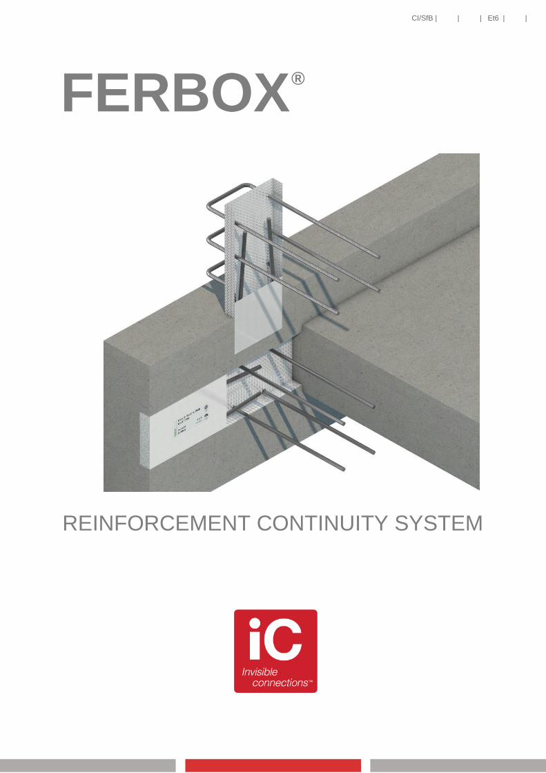
FERBOX
REINFORCEMENT CONTINUITY SYSTEM
®

Introduction
Product description
FERBOX is a reinforcement continuity system,
designed to maintain structural continuity across
construction joints in reinforced concrete structures.
The FERBOX casing houses suitably proven
reinforcement, which is factory pre-bent and factory-
fitted.
On the construction site, the FERBOX unit is
secured inside the formwork at the front face of the
structural member (often a wall), in advance of the
concrete pour.
The FERBOX casing is designed to remain
embedded in the concrete, providing a useful rebate
and key for the subsequent concrete pour. The
galvanised and indented profile of the embedded
casing obviates the need for traditional scabbling at
the joint interface.
After striking the formwork, the casing lid is revealed
and removed, providing access to the connection
legs (starter bars) which lay inside. These legs are
bent outwards (at 90 degrees) by the contractor,
then ordinarily lapped with loose reinforcement of
the subsequent structural member/concrete pour.
Advantages
Almost infinite ability to bespoke casing to
reinforcement requirements.
Dedicated UK-local manufacturing facility for
all ‘specials’ up to 16mm diameter.
UK CARES approval for vertical as well as
horizontal applications.
Product range
22 no. ‘off the shelf’ configurations in 12mm
and 16mm diameter reinforcement.
19 no. ‘special’ bar shape configurations;
dimensionally variable in reinforcement
diameters 10mm, 12mm and 16mm.
Technical Approval
Following a rigorous testing and
evaluation programme, both
plant operations (UK and
Germany) are UK-CARES
approved to the assessment
requirements of EC2
Materials
Embedded casing rolled or fabricated
from galvanised steel sheet.
Steel reinforcement grade B500B or
B500C to BS4449:2005, manufactured
by the ‘hot-rolled and cold-stretched’ or
‘quenched and self-tempered’ process
routes.
Removable lid fabricated from light-
gauge galvanised steel sheet or PVC.
Casing lengths
Standard lengths 1.25m or 1.20m.
Special types - any singular length up
to 2.40m (individual casing lengths are
optimised to suit overall application /
joint length) in 10mm, 12mm and
16mm diameter reinforcement.
2
FERBOX® installation
3
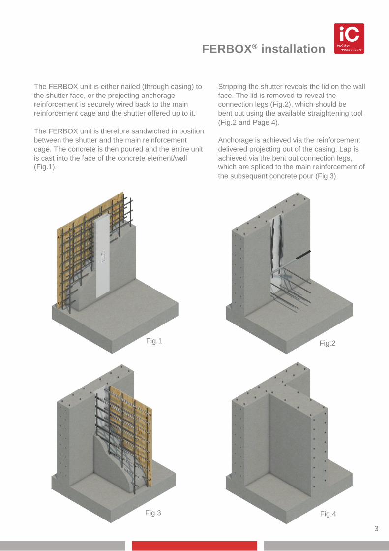
The FERBOX unit is either nailed (through casing) to
the shutter face, or the projecting anchorage
reinforcement is securely wired back to the main
reinforcement cage and the shutter offered up to it.
The FERBOX unit is therefore sandwiched in position
between the shutter and the main reinforcement
cage. The concrete is then poured and the entire unit
is cast into the face of the concrete element/wall
(Fig.1).
Stripping the shutter reveals the lid on the wall
face. The lid is removed to reveal the
connection legs (Fig.2), which should be
bent out using the available straightening tool
(Fig.2 and Page 4).
Anchorage is achieved via the reinforcement
delivered projecting out of the casing. Lap is
achieved via the bent out connection legs,
which are spliced to the main reinforcement of
the subsequent concrete pour (Fig.3).
Fig.4 Fig.3
Fig.2 Fig.1
Casing styles & tools
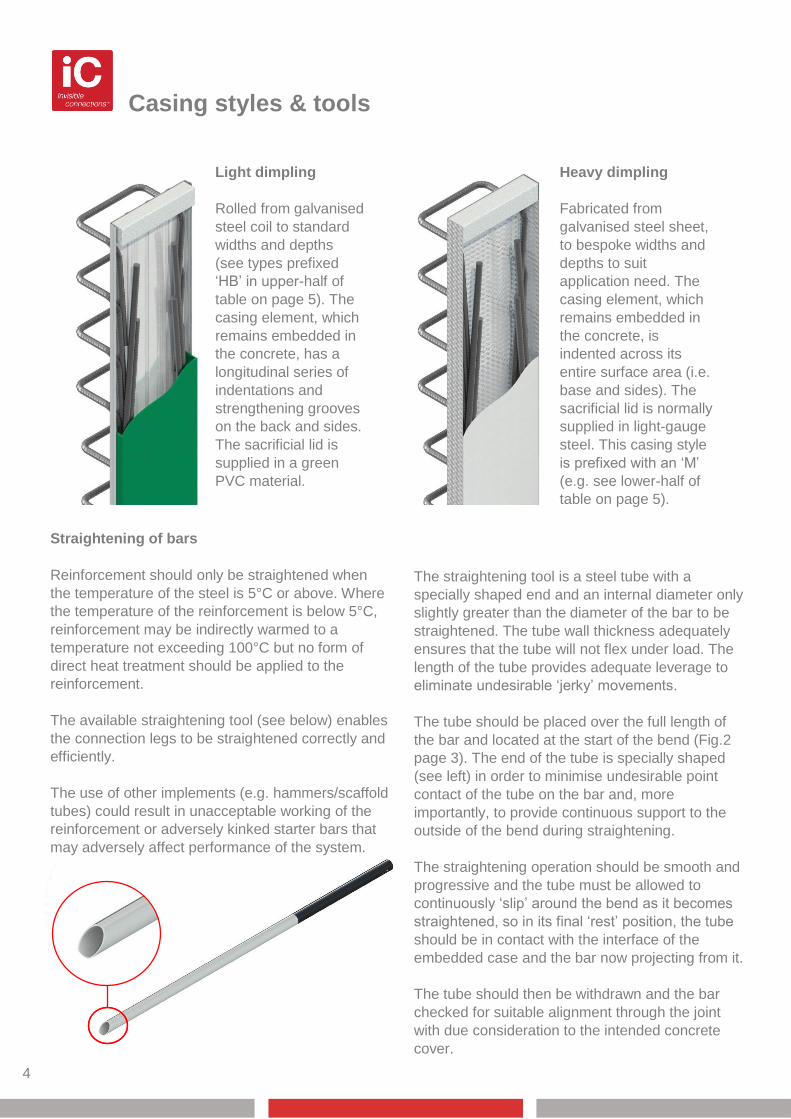
Light dimpling
Rolled from galvanised
steel coil to standard
widths and depths
(see types prefixed
‘HB’ in upper-half of
table on page 5). The
casing element, which
remains embedded in
the concrete, has a
longitudinal series of
indentations and
strengthening grooves
on the back and sides.
The sacrificial lid is
supplied in a green
PVC material.
Heavy dimpling
Fabricated from
galvanised steel sheet,
to bespoke widths and
depths to suit
application need. The
casing element, which
remains embedded in
the concrete, is
indented across its
entire surface area (i.e.
base and sides). The
sacrificial lid is normally
supplied in light-gauge
steel. This casing style
is prefixed with an ‘M’
(e.g. see lower-half of
table on page 5).
The straightening tool is a steel tube with a
specially shaped end and an internal diameter only
slightly greater than the diameter of the bar to be
straightened. The tube wall thickness adequately
ensures that the tube will not flex under load. The
length of the tube provides adequate leverage to
eliminate undesirable ‘jerky’ movements.
The tube should be placed over the full length of
the bar and located at the start of the bend (Fig.2
page 3). The end of the tube is specially shaped
(see left) in order to minimise undesirable point
contact of the tube on the bar and, more
importantly, to provide continuous support to the
outside of the bend during straightening.
The straightening operation should be smooth and
progressive and the tube must be allowed to
continuously ‘slip’ around the bend as it becomes
straightened, so in its final ‘rest’ position, the tube
should be in contact with the interface of the
embedded case and the bar now projecting from it.
The tube should then be withdrawn and the bar
checked for suitable alignment through the joint
with due consideration to the intended concrete
cover.
4
Straightening of bars
Reinforcement should only be straightened when
the temperature of the steel is 5°C or above. Where
the temperature of the reinforcement is below 5°C,
reinforcement may be indirectly warmed to a
temperature not exceeding 100°C but no form of
direct heat treatment should be applied to the
reinforcement.
The available straightening tool (see below) enables
the connection legs to be straightened correctly and
efficiently.
The use of other implements (e.g. hammers/scaffold
tubes) could result in unacceptable working of the
reinforcement or adversely kinked starter bars that
may adversely affect performance of the system.
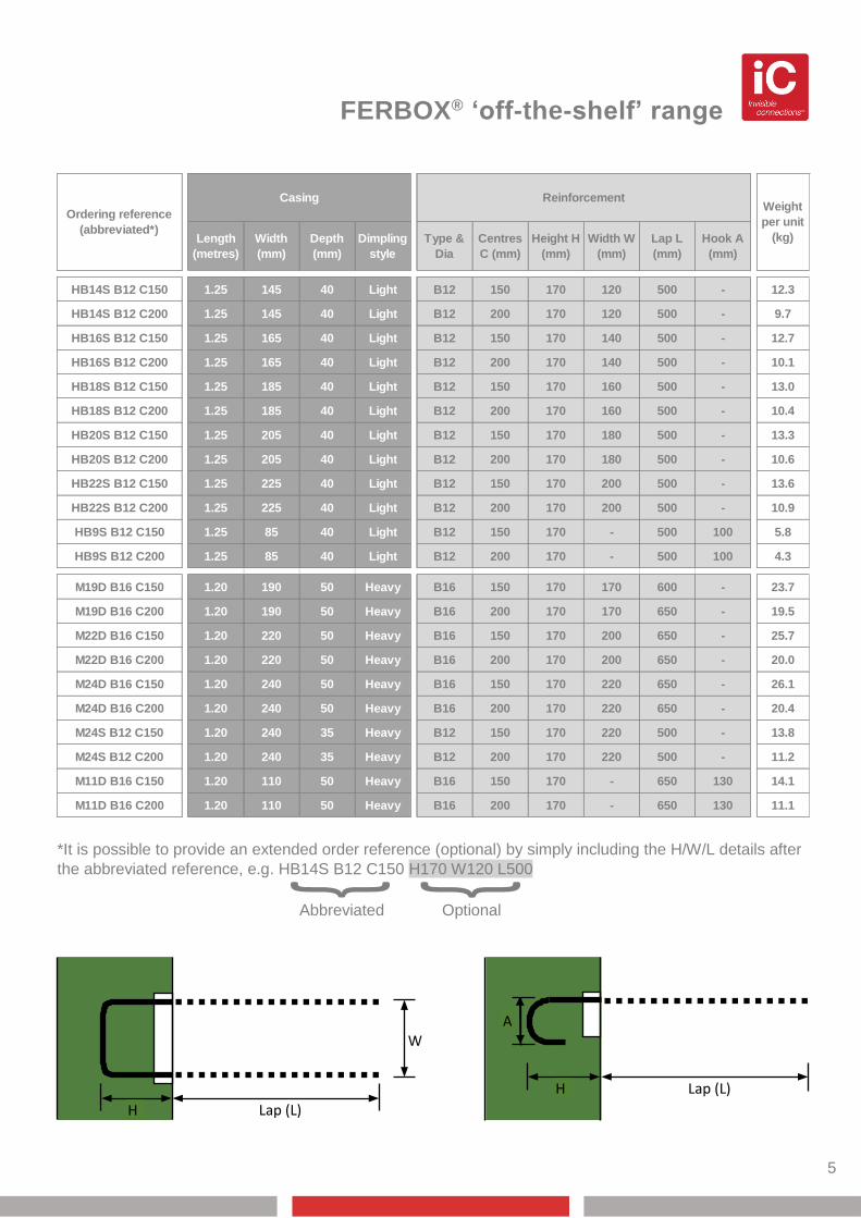
FERBOX® ‘off-the-shelf’ range
Abbreviated Optional
5
HB14S B12 C150 1.25 145 40 Light B12 150 170 120 500 - 12.3
HB14S B12 C200 1.25 145 40 Light B12 200 170 120 500 - 9.7
HB16S B12 C150 1.25 165 40 Light B12 150 170 140 500 - 12.7
HB16S B12 C200 1.25 165 40 Light B12 200 170 140 500 - 10.1
HB18S B12 C150 1.25 185 40 Light B12 150 170 160 500 - 13.0
HB18S B12 C200 1.25 185 40 Light B12 200 170 160 500 - 10.4
HB20S B12 C150 1.25 205 40 Light B12 150 170 180 500 - 13.3
HB20S B12 C200 1.25 205 40 Light B12 200 170 180 500 - 10.6
HB22S B12 C150 1.25 225 40 Light B12 150 170 200 500 - 13.6
HB22S B12 C200 1.25 225 40 Light B12 200 170 200 500 - 10.9
HB9S B12 C150 1.25 85 40 Light B12 150 170 - 500 100 5.8
HB9S B12 C200 1.25 85 40 Light B12 200 170 - 500 100 4.3
M19D B16 C150 1.20 190 50 Heavy B16 150 170 170 600 - 23.7
M19D B16 C200 1.20 190 50 Heavy B16 200 170 170 650 - 19.5
M22D B16 C150 1.20 220 50 Heavy B16 150 170 200 650 - 25.7
M22D B16 C200 1.20 220 50 Heavy B16 200 170 200 650 - 20.0
M24D B16 C150 1.20 240 50 Heavy B16 150 170 220 650 - 26.1
M24D B16 C200 1.20 240 50 Heavy B16 200 170 220 650 - 20.4
M24S B12 C150 1.20 240 35 Heavy B12 150 170 220 500 - 13.8
M24S B12 C200 1.20 240 35 Heavy B12 200 170 220 500 - 11.2
M11D B16 C150 1.20 110 50 Heavy B16 150 170 - 650 130 14.1
M11D B16 C200 1.20 110 50 Heavy B16 200 170 - 650 130 11.1
Casing ReinforcementWeight
per unit
(kg)
Ordering reference
(abbreviated*)Length
(metres)
Width
(mm)
Depth
(mm)
Dimpling
style
Type &
Dia
Centres
C (mm)
Hook A
(mm)
Height H
(mm)
Width W
(mm)
Lap L
(mm)
*It is possible to provide an extended order reference (optional) by simply including the H/W/L details after
the abbreviated reference, e.g. HB14S B12 C150 H170 W120 L500
} }
H
H
A
Lap (L)
W
Lap (L)
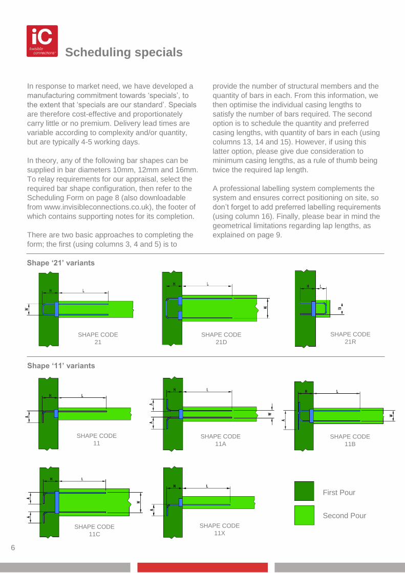
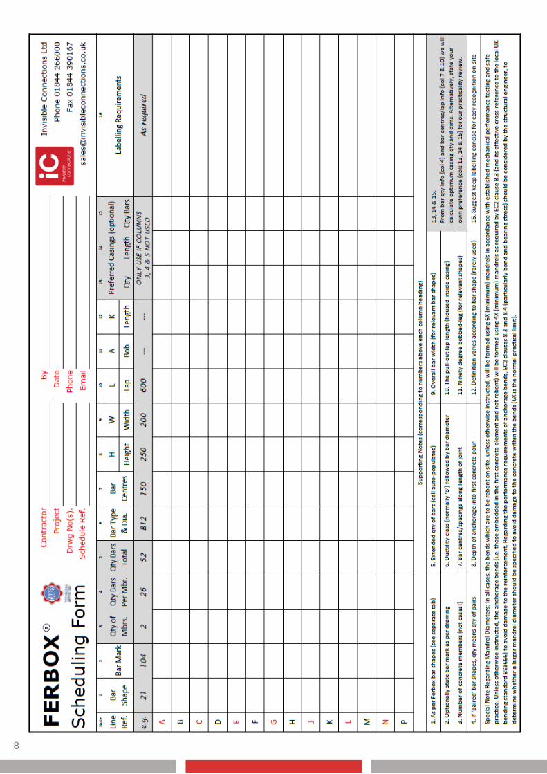
Scheduling specials
6
In response to market need, we have developed a
manufacturing commitment towards ‘specials’, to
the extent that ‘specials are our standard’. Specials
are therefore cost-effective and proportionately
carry little or no premium. Delivery lead times are
variable according to complexity and/or quantity,
but are typically 4-5 working days.
In theory, any of the following bar shapes can be
supplied in bar diameters 10mm, 12mm and 16mm.
To relay requirements for our appraisal, select the
required bar shape configuration, then refer to the
Scheduling Form on page 8 (also downloadable
from www.invisibleconnections.co.uk), the footer of
which contains supporting notes for its completion.
There are two basic approaches to completing the
form; the first (using columns 3, 4 and 5) is to
provide the number of structural members and the
quantity of bars in each. From this information, we
then optimise the individual casing lengths to
satisfy the number of bars required. The second
option is to schedule the quantity and preferred
casing lengths, with quantity of bars in each (using
columns 13, 14 and 15). However, if using this
latter option, please give due consideration to
minimum casing lengths, as a rule of thumb being
twice the required lap length.
A professional labelling system complements the
system and ensures correct positioning on site, so
don’t forget to add preferred labelling requirements
(using column 16). Finally, please bear in mind the
geometrical limitations regarding lap lengths, as
explained on page 9.
Shape ‘21’ variants
Shape ‘11’ variants
SHAPE CODE
21
Second Pour
First Pour
SHAPE CODE
11X SHAPE CODE
11C
SHAPE CODE
11B
SHAPE CODE
11A
SHAPE CODE
11
SHAPE CODE
21R SHAPE CODE
21D
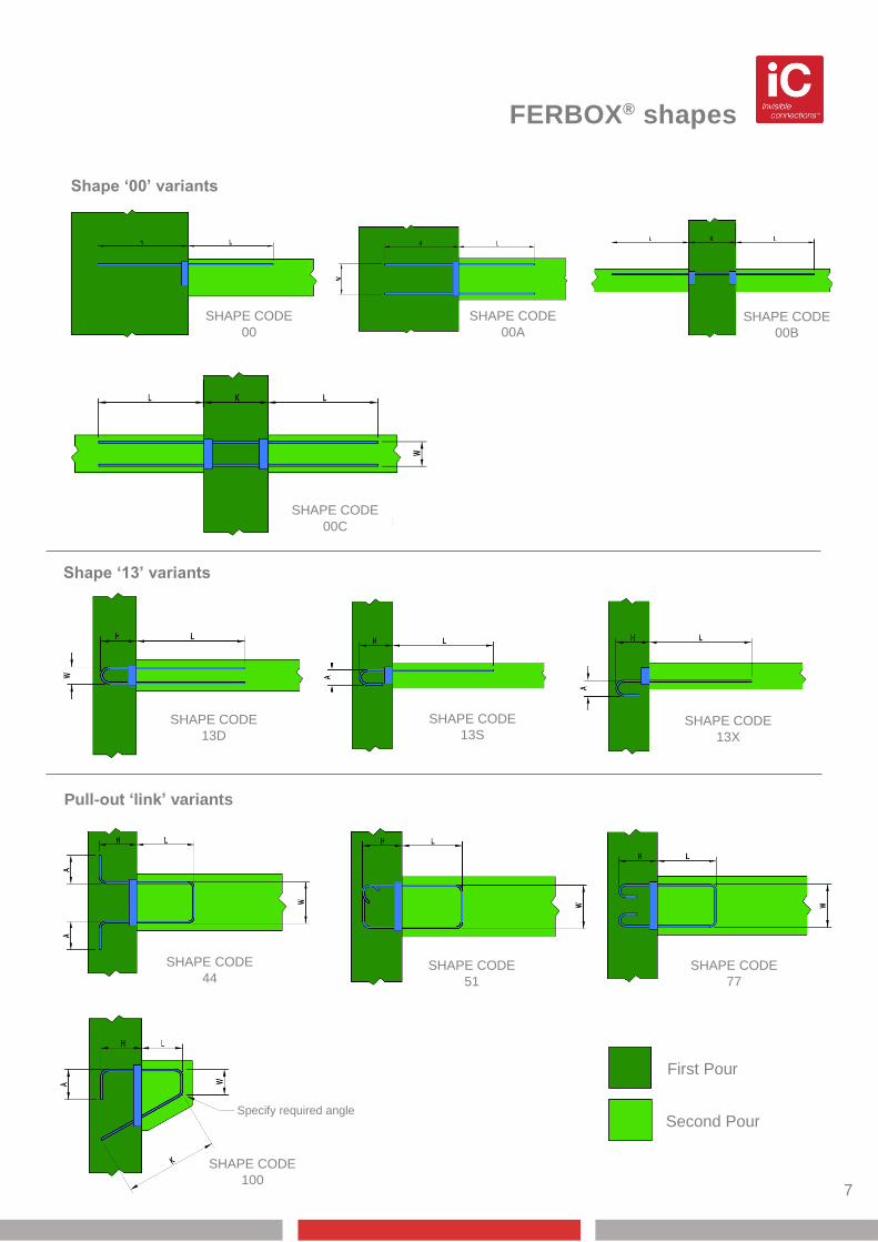
FERBOX® shapes
7
Shape ‘13’ variants
Shape ‘00’ variants
Shape ‘13’ variants
Pull-out ‘link’ variants
First Pour
Second Pour
SHAPE CODE
77
SHAPE CODE
100
SHAPE CODE
44 SHAPE CODE
51
SHAPE CODE
13D
SHAPE CODE
13S SHAPE CODE
13X
SHAPE CODE
00C
SHAPE CODE
00
SHAPE CODE
00A
SHAPE CODE
00B
Specify required angle
8
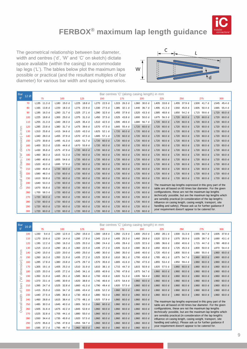
FERBOX® maximum lap length guidance
9
The geometrical relationship between bar diameter,
width and centres (‘d’, ‘W’ and ‘C’ on sketch) dictate
space available (within the casing) to accommodate
lap legs (‘L’). The tables below plot the maximum laps
possible or practical (and the resultant multiples of bar
diameter) for various bar width and spacing scenarios.
70 L135 11.3 d L180 15.0 d L225 18.8 d L270 22.5 d L315 26.3 d L360 30.0 d L405 33.8 d L455 37.9 d L500 41.7 d L545 45.4 d
80 L165 13.8 d L220 18.3 d L275 22.9 d L330 27.5 d L385 32.1 d L440 36.7 d L495 41.3 d L550 45.8 d L605 50.4 d L665 55.4 d
90 L195 16.3 d L260 21.7 d L325 27.1 d L390 32.5 d L455 37.9 d L520 43.3 d L585 48.8 d L650 54.2 d L715 59.6 d L720 60.0 d
100 L225 18.8 d L300 25.0 d L375 31.3 d L450 37.5 d L525 43.8 d L600 50.0 d L675 56.3 d L720 60.0 d L720 60.0 d L720 60.0 d
110 L255 21.3 d L340 28.3 d L425 35.4 d L510 42.5 d L595 49.6 d L680 56.7 d L720 60.0 d L720 60.0 d L720 60.0 d L720 60.0 d
120 L285 23.8 d L380 31.7 d L475 39.6 d L570 47.5 d L665 55.4 d L720 60.0 d L720 60.0 d L720 60.0 d L720 60.0 d L720 60.0 d
130 L310 25.8 d L415 34.6 d L520 43.3 d L625 52.1 d L720 60.0 d L720 60.0 d L720 60.0 d L720 60.0 d L720 60.0 d L720 60.0 d
140 L340 28.3 d L455 37.9 d L570 47.5 d L685 57.1 d L720 60.0 d L720 60.0 d L720 60.0 d L720 60.0 d L720 60.0 d L720 60.0 d
150 L370 30.8 d L495 41.3 d L620 51.7 d L720 60.0 d L720 60.0 d L720 60.0 d L720 60.0 d L720 60.0 d L720 60.0 d L720 60.0 d
160 L400 33.3 d L535 44.6 d L670 55.8 d L720 60.0 d L720 60.0 d L720 60.0 d L720 60.0 d L720 60.0 d L720 60.0 d L720 60.0 d
170 L430 35.8 d L575 47.9 d L720 60.0 d L720 60.0 d L720 60.0 d L720 60.0 d L720 60.0 d L720 60.0 d L720 60.0 d L720 60.0 d
180 L460 38.3 d L615 51.3 d L720 60.0 d L720 60.0 d L720 60.0 d L720 60.0 d L720 60.0 d L720 60.0 d L720 60.0 d L720 60.0 d
190 L490 40.8 d L655 54.6 d L720 60.0 d L720 60.0 d L720 60.0 d L720 60.0 d L720 60.0 d L720 60.0 d L720 60.0 d L720 60.0 d
200 L520 43.3 d L695 57.9 d L720 60.0 d L720 60.0 d L720 60.0 d L720 60.0 d L720 60.0 d L720 60.0 d L720 60.0 d L720 60.0 d
210 L550 45.8 d L720 60.0 d L720 60.0 d L720 60.0 d L720 60.0 d L720 60.0 d L720 60.0 d L720 60.0 d L720 60.0 d L720 60.0 d
220 L580 48.3 d L720 60.0 d L720 60.0 d L720 60.0 d L720 60.0 d L720 60.0 d L720 60.0 d L720 60.0 d L720 60.0 d L720 60.0 d
230 L610 50.8 d L720 60.0 d L720 60.0 d L720 60.0 d L720 60.0 d L720 60.0 d L720 60.0 d L720 60.0 d L720 60.0 d L720 60.0 d
240 L640 53.3 d L720 60.0 d L720 60.0 d L720 60.0 d L720 60.0 d L720 60.0 d
250 L670 55.8 d L720 60.0 d L720 60.0 d L720 60.0 d L720 60.0 d L720 60.0 d
260 L700 58.3 d L720 60.0 d L720 60.0 d L720 60.0 d L720 60.0 d L720 60.0 d
270 L720 60.0 d L720 60.0 d L720 60.0 d L720 60.0 d L720 60.0 d L720 60.0 d
280 L720 60.0 d L720 60.0 d L720 60.0 d L720 60.0 d L720 60.0 d L720 60.0 d
290 L720 60.0 d L720 60.0 d L720 60.0 d L720 60.0 d L720 60.0 d L720 60.0 d
300 L720 60.0 d L720 60.0 d L720 60.0 d L720 60.0 d L720 60.0 d L720 60.0 d
Bar centres 'C' (along casing length) in mm
75 100 125 150 175 200 225 250 275 300
The maximum lap lengths expressed in this grey part of the
table are all based on 60 times bar diameter. For the given
configurations, these are not the maximum lap lengths
technically possible, but are the maximum lap lengths which
are sensibly practical (in consideration of the lap length's
influence on casing length, casing weight, transport, site
handling and safety). Please ask us for further guidance if
your requirement doesn't appear to be catered for.
12 ØBar
'd'
Overa
ll w
idth
of
bars
('W
' dim
ensio
n)
in m
m
100 L150 9.4 d L200 12.5 d L250 15.6 d L300 18.8 d L350 21.9 d L400 25.0 d L450 28.1 d L500 31.3 d L555 34.7 d L605 37.8 d
110 L170 10.6 d L230 14.4 d L285 17.8 d L345 21.6 d L405 25.3 d L460 28.8 d L520 32.5 d L575 35.9 d L635 39.7 d L690 43.1 d
120 L195 12.2 d L260 16.3 d L325 20.3 d L390 24.4 d L455 28.4 d L520 32.5 d L585 36.6 d L650 40.6 d L715 44.7 d L780 48.8 d
130 L215 13.4 d L290 18.1 d L360 22.5 d L435 27.2 d L505 31.6 d L580 36.3 d L650 40.6 d L725 45.3 d L800 50.0 d L870 54.4 d
140 L240 15.0 d L320 20.0 d L400 25.0 d L480 30.0 d L560 35.0 d L640 40.0 d L720 45.0 d L800 50.0 d L880 55.0 d L960 60.0 d
150 L260 16.3 d L350 21.9 d L435 27.2 d L525 32.8 d L610 38.1 d L700 43.8 d L785 49.1 d L875 54.7 d L960 60.0 d L960 60.0 d
160 L285 17.8 d L380 23.8 d L475 29.7 d L570 35.6 d L665 41.6 d L760 47.5 d L855 53.4 d L950 59.4 d L960 60.0 d L960 60.0 d
170 L305 19.1 d L405 25.3 d L510 31.9 d L610 38.1 d L715 44.7 d L815 50.9 d L920 57.5 d L960 60.0 d L960 60.0 d L960 60.0 d
180 L325 20.3 d L435 27.2 d L545 34.1 d L655 40.9 d L765 47.8 d L875 54.7 d L960 60.0 d L960 60.0 d L960 60.0 d L960 60.0 d
190 L350 21.9 d L465 29.1 d L585 36.6 d L700 43.8 d L820 51.3 d L935 58.4 d L960 60.0 d L960 60.0 d L960 60.0 d L960 60.0 d
200 L370 23.1 d L495 30.9 d L620 38.8 d L745 46.6 d L870 54.4 d L960 60.0 d L960 60.0 d L960 60.0 d L960 60.0 d L960 60.0 d
210 L395 24.7 d L525 32.8 d L660 41.3 d L790 49.4 d L920 57.5 d L960 60.0 d L960 60.0 d L960 60.0 d L960 60.0 d L960 60.0 d
220 L415 25.9 d L555 34.7 d L695 43.4 d L835 52.2 d L960 60.0 d L960 60.0 d L960 60.0 d L960 60.0 d L960 60.0 d L960 60.0 d
230 L440 27.5 d L585 36.6 d L730 45.6 d L880 55.0 d L960 60.0 d L960 60.0 d L960 60.0 d L960 60.0 d L960 60.0 d L960 60.0 d
240 L460 28.8 d L615 38.4 d L770 48.1 d L925 57.8 d L960 60.0 d L960 60.0 d
250 L485 30.3 d L645 40.3 d L805 50.3 d L960 60.0 d L960 60.0 d L960 60.0 d
260 L505 31.6 d L675 42.2 d L845 52.8 d L960 60.0 d L960 60.0 d L960 60.0 d
270 L525 32.8 d L705 44.1 d L880 55.0 d L960 60.0 d L960 60.0 d L960 60.0 d
280 L550 34.4 d L735 45.9 d L920 57.5 d L960 60.0 d L960 60.0 d L960 60.0 d
290 L570 35.6 d L765 47.8 d L955 59.7 d L960 60.0 d L960 60.0 d L960 60.0 d
300 L595 37.2 d L795 49.7 d L960 60.0 d L960 60.0 d L960 60.0 d L960 60.0 d
The maximum lap lengths expressed in this grey part of the
table are all based on 60 times bar diameter. For the given
configurations, these are not the maximum lap lengths
technically possible, but are the maximum lap lengths which
are sensibly practical (in consideration of the lap length's
influence on casing length, casing weight, transport, site
handling and safety). Please ask us for further guidance if
your requirement doesn't appear to be catered for.
Overa
ll w
idth
of
bars
('W
' dim
ensio
n)
in m
m
Bar
'd'16 Ø
Bar centres 'C' (along casing length) in mm
75 100 125 150 175 200 225 250 275 300
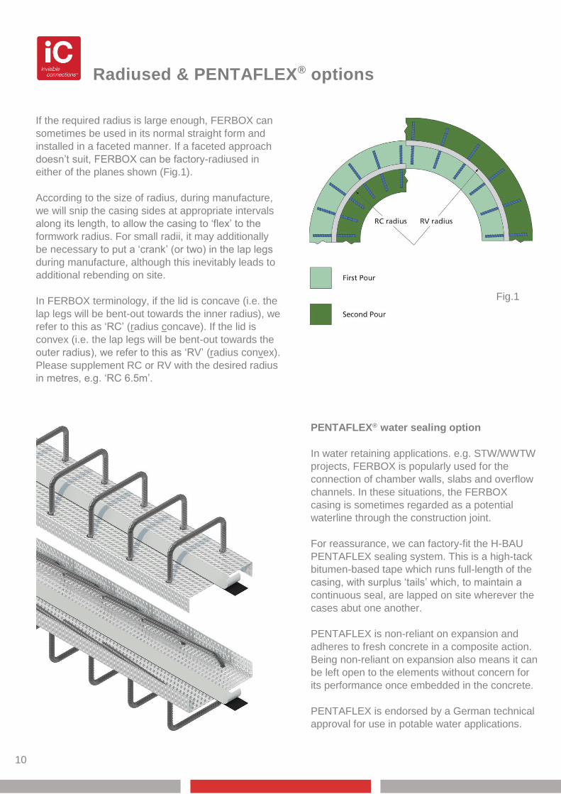
Radiused & PENTAFLEX® options
If the required radius is large enough, FERBOX can
sometimes be used in its normal straight form and
installed in a faceted manner. If a faceted approach
doesn’t suit, FERBOX can be factory-radiused in
either of the planes shown (Fig.1).
According to the size of radius, during manufacture,
we will snip the casing sides at appropriate intervals
along its length, to allow the casing to ‘flex’ to the
formwork radius. For small radii, it may additionally
be necessary to put a ‘crank’ (or two) in the lap legs
during manufacture, although this inevitably leads to
additional rebending on site.
In FERBOX terminology, if the lid is concave (i.e. the
lap legs will be bent-out towards the inner radius), we
refer to this as ‘RC’ (radius concave). If the lid is
convex (i.e. the lap legs will be bent-out towards the
outer radius), we refer to this as ‘RV’ (radius convex).
Please supplement RC or RV with the desired radius
in metres, e.g. ‘RC 6.5m’.
10
PENTAFLEX® water sealing option
In water retaining applications. e.g. STW/WWTW
projects, FERBOX is popularly used for the
connection of chamber walls, slabs and overflow
channels. In these situations, the FERBOX
casing is sometimes regarded as a potential
waterline through the construction joint.
For reassurance, we can factory-fit the H-BAU
PENTAFLEX sealing system. This is a high-tack
bitumen-based tape which runs full-length of the
casing, with surplus ‘tails’ which, to maintain a
continuous seal, are lapped on site wherever the
cases abut one another.
PENTAFLEX is non-reliant on expansion and
adheres to fresh concrete in a composite action.
Being non-reliant on expansion also means it can
be left open to the elements without concern for
its performance once embedded in the concrete.
PENTAFLEX is endorsed by a German technical
approval for use in potable water applications.
Fig.1
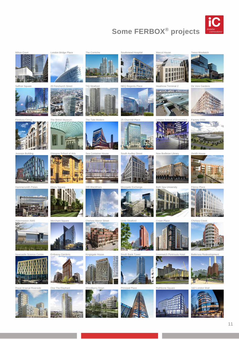
Some FERBOX® projects
11
Milton Court
London Bridge Place
The Corniche
Southmead Hospital
Marcol House
Tesco Woolwich
Tesco Woolwich
Saffron Square
De Vere Gardens
Heathrow Terminal 2
NEQ Regents Place
TIQ Stratford
20 Fenchurch Street
20
Ebury Square
Glasgow School of Arts
The British Museum
Royal Arsenal Riverside
Newcastle Science Centre
Aldermaston AWE
Hammersmith Palais
Jessops Building
Finsbury Circus
25 Churchill Place
Chelsea Manor Street
Merchant Square
Fitzroy Place
Bath Spa University
Moorgate Exchange
240 Blackfriars
Zenith House
New Bodleian Library
South Audley Street
Factory 2050
London School of Economics
Sea Container House
Principal Place
Woodberry Down
One The Elephant
Battersea Redevelopment
Greenwich Peninsula Hotel
South Bank Tower
Chelsea Creek
Crown Place
Unite Stratford
Kingsgate House
Embassy Gardens
1&2 London Wall
Rathbone Square
The Tate Modern
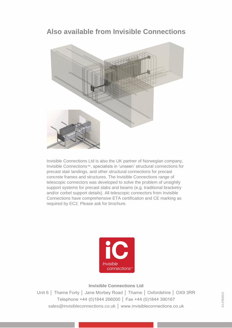
Also available from Invisible Connections
Invisible Connections Ltd
Unit 6 │ Thame Forty │ Jane Morbey Road │ Thame │ Oxfordshire │ OX9 3RR
Telephone +44 (0)1844 266000 │ Fax +44 (0)1844 390167
[email protected] │ www.invisibleconnections.co.uk ICL/F
B/0
91
5
Invisible Connections Ltd is also the UK partner of Norwegian company,
Invisible Connections™, specialists in ‘unseen’ structural connections for
precast stair landings, and other structural connections for precast
concrete frames and structures. The Invisible Connections range of
telescopic connectors was developed to solve the problem of unsightly
support systems for precast slabs and beams (e.g. traditional bracketry
and/or corbel support details). All telescopic connectors from Invisible
Connections have comprehensive ETA certification and CE marking as
required by EC2. Please ask for brochure.