Embed Size (px)
Citation preview
FERITSCOPE® MP30
Order number 902-512 Version 2.0 Issue date 12/2001Subject to changes.
Operating Manual FERITSCOPE® MP30 (2.0 - 12/01) Page 1

Page 2 Operating Manual FERITSCOPE® MP30 (2.0 - 12/01)
1 Conventions
1.1 Symbols and Styles Used
The following symbols and styles are used in this manual:
1.2 General Note
Illustrations of displays in this manual are examples only. Actual ferrite content measurement data, the prompt lines on the dis-play (e.g. the number of the selected application, the number of mea-surements stored in a particular application) or the results of an evalua-tion depend on your individual application. It is possible that different numbers may appear on the display. This is not an indication of any malfunction.
Safety remarks and warnings of possible damage to the instrument or the accessories or danger to the operating personnel.
ENTER Refers to instrument keys (e.g. ENTER key)
ON/OFF + ENTER Refers to instrument keys, which have to be pressed immediately one after the other Do not keep both keys pressed!
_____________ 24.8 Appl: 2 WRC-FN Blck: 5 n= 2
_____________
Simplified representation of the display with all ele-ments relevant for the current action
Std. dev. Style used for texts appearing on a printout
/ 1 / Cross reference to additional literature:see "17 Additional Literature", beginning on page 205
Operating Manual FERITSCOPE® MP30 (2.0 - 12/01) Page 3

Page 4 Operating Manual FERITSCOPE® MP30 (2.0 - 12/01)
2 Notes Concerning the Operation of the Instrument and Handling the Accessories
2.1 Proper Use of the Instrument
The FERITSCOPE® MP30 is suitable for ferrit content measurement in weld metal and clad layers of austenitic or Duplex stainless steel and for determi-nation of the ratio of martensite in austenitic stainless steels. Only accessories recommended or used by Fischer (e.g. AC power supply, probes, printer) may be assigned to the instrument.
2.2 Requirements on the Operating Personnel
The instrument may be operated by suitably qualified personnel only.
Knowledge about configuration, operation and programming of the computer as well as of the software used, is necessary to connect the instrument to a computer. Refer to the corresponding operator manuals if necessary.
2.3 Power Connection
To prevent damage to the instruments or wrong measurement re-sults due to wrong A/C line voltage, connect the instruments to a power outlet only with the AC power supply supplied by Fischer. The A/C line voltage must agree with the A/C line voltage rating on the serial number plate of the AC power supply.
2.4 Environmental Conditions for Operation and Storage of Instrument and Accessories
The instrument FERITSCOPE® MP30 is designed to meet and comply with all requirements as set forth in the EC Guideline 89/ 336/ EEC “Electromag-netic Compatibility”. The measured ferrite contents are not influenced by the highest level of interference as stated in the guideline EN 50082-1 (which re-fers to IEC 801-2, 801-3 and 801-4).In particular, the instrument is effectively shielded from electromagnetic fields (e. g. motors, power lines, etc.).Instrument and accessories are designed for use at temperatures between 5
Operating Manual FERITSCOPE® MP30 (2.0 - 12/01) Page 5
and 45 °C (41 ... 113°F). The equipment may be stored at temperatures bet-ween 5 and 60°C (41 ... 140°F).
Avoid excessivly hot operation environment!Temperatures behind windows (e.g. in cars) in direct sunshine rise easily above 60 °C (140°F). To avoid damage to the instrument or the accessories by heat, do not keep or store the instrument or the accessories in such pla-ces.
Avoid direct contact with fluids!Danger of short circuits instrument and accessories (in particular the AC power supply).
Instrument and accessories may be operated, kept and stored only in places where the environmental relative humidity is bet-ween 30 and 90 % (non-condensing).
Instrument and accessories are not acid resistant! Make sure to avoid direct contact of acid or acid solutions with the instrument or the accessories.
Do not operate instrument and accessories in an explosive at-mosphere!
Protect instrument and accessories from static charge! Electric discharges may delete internally stored data or damage internal components.
2.5 Opening the Instrument or the Accessories
The battery is the only user-serviceable part of the instrument FERITSCOPE® MP30 and the accessories.
To prevent damages to the internal components, the instrument or the accessories should only be opened to replace the battery.Further servicing of the instrument or the accessories should only be performed by Fischer authorized service technicians.
Page 6 Operating Manual FERITSCOPE® MP30 (2.0 - 12/01)
2.6 Handling the Probes
When measuring, the probe tips is placed directly on the material to be measu-red. To reduce probe tip wear, keep the following in mind:
Avoid hard impacts! Place the probes rapidly, but gently on the surface of the material to be maesured!
Do not drag the probe over the surface of the the material to be measured!
Do not place the probe on hot or acid-covered surfaces, do not im-merse the probes into liquids!
2.7 Handling the Base and the Calibration Standards
The base and the calibration standards are used to normalize and calibrate the FERITSCOPE® MP30. The good condition of the Base and the calibration standards is an important requirement for an accurate normalization and calibration.
To ensure the perfect condition of the Base and the calibration standards, keep the following in mind:
To reduce the wear and tear of the Base and the calibration stan-dards, the Base and the calibration standards should only be used for normalization and corrective calibration. Do not use them for test measurements!
Do not soil or scratch the calibration standards! Corroded, soiled or scratched calibration standard or standards with deep gouges have to be replaced by new standards.
To protect the calibration standards from dirt or damage, keep and store the standards in the supplied calibration standard case.
2.8 Warranty
Fischer will not be responsible or honor any warranty claims for the following cases:
� Misuse of the instrument or the accessories
� Improper use of the instrument or accessories (e. g. operating in an explo-sive, highly corrosive or excessively hot atmosphere)
Operating Manual FERITSCOPE® MP30 (2.0 - 12/01) Page 7

Page 8 Operating Manual FERITSCOPE® MP30 (2.0 - 12/01)
3 Instrument and Accessories Description
3.1 Instrument
3.1.1 Measurement Application Capabilities / Intended Use
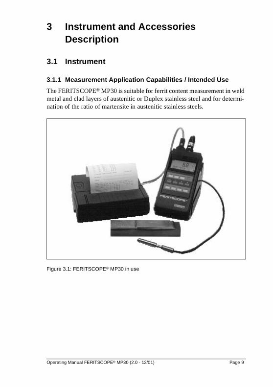
The FERITSCOPE® MP30 is suitable for ferrit content measurement in weld metal and clad layers of austenitic or Duplex stainless steel and for determi-nation of the ratio of martensite in austenitic stainless steels.
Figure 3.1: FERITSCOPE® MP30 in use
Operating Manual FERITSCOPE® MP30 (2.0 - 12/01) Page 9
3.1.2 Test Method
The instrument uses the magnetic induction test method according to/ 9 / 15 / or / 16 / whereby the ferrite content is obtained from the magnetic permeability.
3.1.3 Unit of Measurement
The measurements can be displayed in point count ferrite (Fe%) or in ferrite numbers (FN).Selecting the unit of measurement for the current application:see "11.4.3 Instrument Configuration", beginning on page 137.
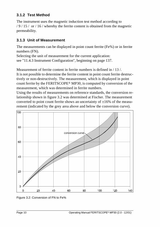
Measurement of ferrite content in ferrite numbers is defined in / 13 /. It is not possible to determine the ferrite content in point count ferrite destruc-tively or non-destructively. The measurement, which is displayed in point count ferrite by the FERITSCOPE® MP30, is computed by conversion of the measurement, which was determined in ferrite numbers.Using the results of measurements on reference standards, the conversion re-lationship shown in figure 3.2 was determined at Fischer. The measurement converted to point count ferrite shows an uncertainty of ±16% of the measu-rement (indicated by the grey area above and below the conversion curve).
Figure 3.2: Conversion of FN to Fe%
conversion curve
Page 10 Operating Manual FERITSCOPE® MP30 (2.0 - 12/01)
3.1.4 Front and Rear View
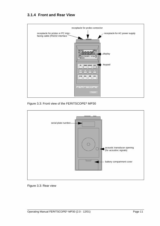
Figure 3.3: Front view of the FERITSCOPE® MP30
Figure 3.3: Rear view
receptacle for AC power supplyreceptacle for printer or PC inter-facing cable (RS232 interface
display
keypad
receptacle for probe connector
serial plate number
acoustic transducer opening (for acoustivc signals)
battery compartment cover
Operating Manual FERITSCOPE® MP30 (2.0 - 12/01) Page 11
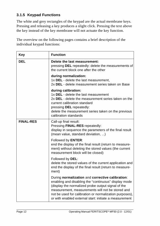
3.1.5 Keypad Functions
The white and grey rectangles of the keypad are the actual membrane keys. Pressing and releasing a key produces a slight click. Pressing the text above the key instead of the key membrane will not actuate the key function.
The overview on the following pages contains a brief description of the individual keypad functions:
Key Function
DEL Delete the last measurement:pressing DEL repeatedly: delete the measurements of the current block one after the other
during normalization:1x DEL - delete the last measurement, 2x DEL - delete measurement series taken on Base
during calibration:1x DEL - delete the last measurement2x DEL - delete the measurement series taken on thecurrent calibration standardpressing DEL repeatedly:delete the measurement series taken on the previouscalibration standards
FINAL-RES Call-up final result:Pressing FINAL-RES repeatedly: display in sequence the parameters of the final result (mean value, standard deviation, ...)
Followed by ENTER:end the display of the final result (return to measure-ment) without deleting the stored values (the current measurement block will be closed)
Followed by DEL:delete the stored values of the current application and end the display of the final result (return to measure-ment)
During normalization and corrective calibration:enabling and disabling the “continuous” display mode (display the normalized probe output signal of the measurement, measurements will not be stored and not be used for calibration or normalization purposes), or with enabled external start: initiate a measurement
Page 12 Operating Manual FERITSCOPE® MP30 (2.0 - 12/01)
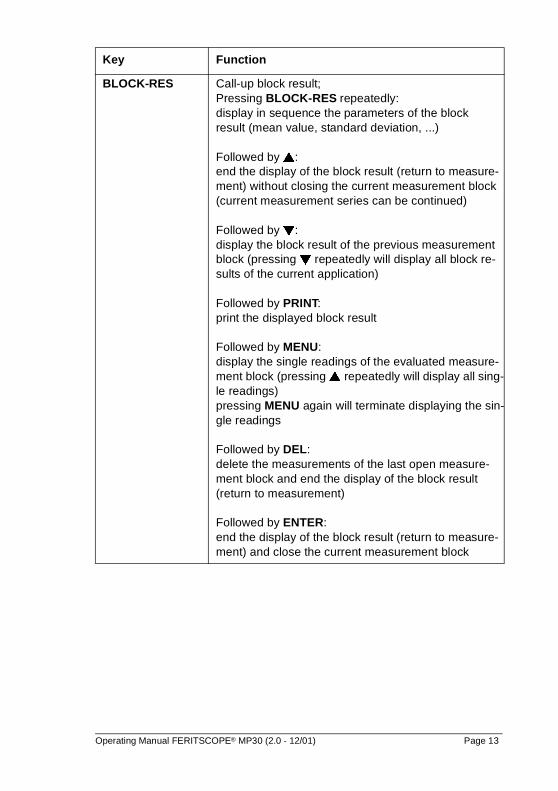
BLOCK-RES Call-up block result; Pressing BLOCK-RES repeatedly:display in sequence the parameters of the block result (mean value, standard deviation, ...)
Followed by �: end the display of the block result (return to measure-ment) without closing the current measurement block (current measurement series can be continued)
Followed by �: display the block result of the previous measurement block (pressing � repeatedly will display all block re-sults of the current application)
Followed by PRINT: print the displayed block result
Followed by MENU: display the single readings of the evaluated measure-ment block (pressing � repeatedly will display all sing-le readings)pressing MENU again will terminate displaying the sin-gle readings
Followed by DEL: delete the measurements of the last open measure-ment block and end the display of the block result (return to measurement)
Followed by ENTER:end the display of the block result (return to measure-ment) and close the current measurement block
Key Function
Operating Manual FERITSCOPE® MP30 (2.0 - 12/01) Page 13
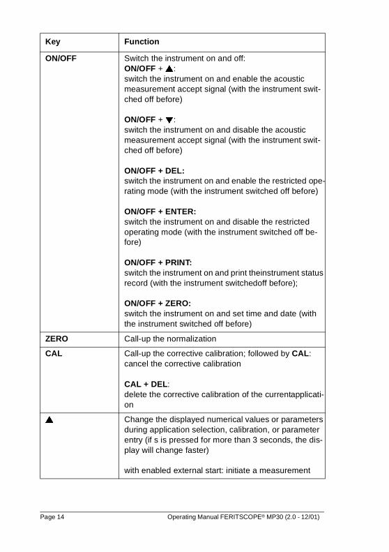
ON/OFF Switch the instrument on and off:ON/OFF + �: switch the instrument on and enable the acoustic measurement accept signal (with the instrument swit-ched off before)
ON/OFF + �:switch the instrument on and disable the acoustic measurement accept signal (with the instrument swit-ched off before)
ON/OFF + DEL:switch the instrument on and enable the restricted ope-rating mode (with the instrument switched off before)
ON/OFF + ENTER:switch the instrument on and disable the restricted operating mode (with the instrument switched off be-fore)
ON/OFF + PRINT:switch the instrument on and print theinstrument status record (with the instrument switchedoff before);
ON/OFF + ZERO:switch the instrument on and set time and date (with the instrument switched off before)
ZERO Call-up the normalization
CAL Call-up the corrective calibration; followed by CAL: cancel the corrective calibration
CAL + DEL:delete the corrective calibration of the currentapplicati-on
� Change the displayed numerical values or parameters during application selection, calibration, or parameter entry (if s is pressed for more than 3 seconds, the dis-play will change faster)
with enabled external start: initiate a measurement
Key Function
Page 14 Operating Manual FERITSCOPE® MP30 (2.0 - 12/01)
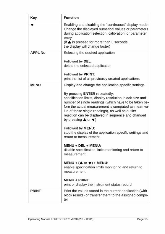
� Enabling and disabling the “continuous” display mode:Change the displayed numerical values or parameters during application selection, calibration, or parameter entry (if � is pressed for more than 3 seconds, the display will change faster)
APPL No Selecting the desired application
Followed by DEL:delete the selected application
Followed by PRINT:print the list of all previously created applications
MENU Display and change the application specific settings
By pressing ENTER repeatedly:specification limits, display resolution, block size and number of single readings (which have to be taken be-fore the actual measurement is computed as mean va-lue of these single readings), as well as outlier rejection can be displayed in sequence and changed by pressing � or �)
Followed by MENU:stop the display of the application specific settings and return to measurement
MENU + DEL + MENU: disable specification limits monitoring and return to measurement
MENU + (� or �) + MENU:enable specification limits monitoring and return to measurement
MENU + PRINT: print or display the instrument status record
PRINT Print the values stored in the current application (with block results) or transfer them to the assigned compu-ter
Key Function
Operating Manual FERITSCOPE® MP30 (2.0 - 12/01) Page 15
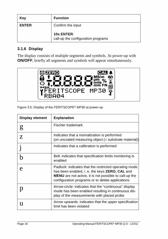
3.1.6 Display
The display consists of multiple segments and symbols. At power-up with ON/OFF, briefly all segments and symbols will appear simultaneously.
Figure 3.5: Display of the FERITSCOPE® MP30 at power-up
ENTER Confirm the input
10x ENTER: call-up the configuration programs
Display element Explanation
g Fischer trademark
z Indicates that a normalization is performed (on uncoated measuring object (= substrate material))
j Indicates that a calibration is performed
b Bell: indicates that specification limits monitoring is enabled
e Padlock: indicates that the restricted operating mode has been enabled, i. e. the keys ZERO, CAL and MENU are not active, it is not possible to call-up the configuration programs or to delete applications
p Arrow-circle: indicates that the “continuous” display mode has been enabled resulting in continuous dis-play of the measurements with placed probe
u Arrow upwards: indicates that the upper specification limit has been violated
Key Function
Page 16 Operating Manual FERITSCOPE® MP30 (2.0 - 12/01)
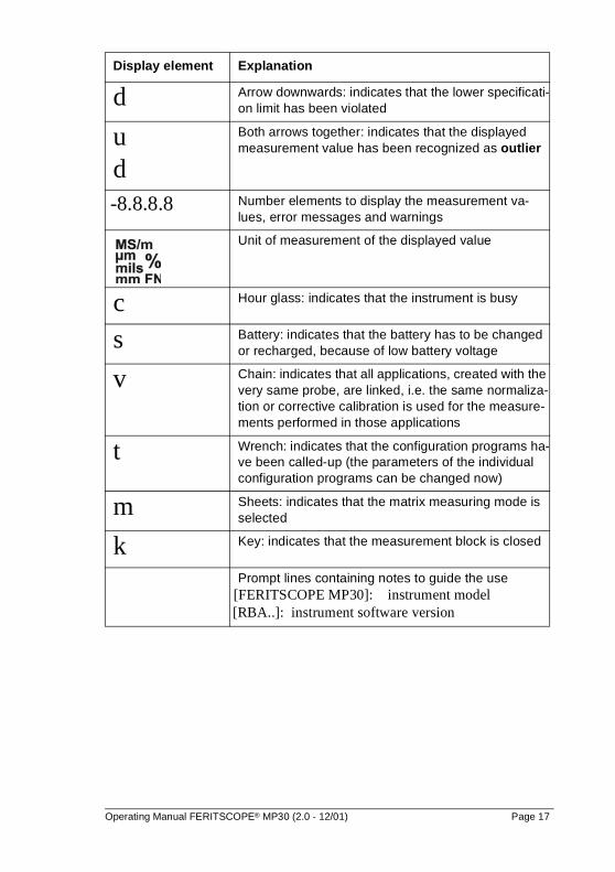
d Arrow downwards: indicates that the lower specificati-on limit has been violated
ud
Both arrows together: indicates that the displayed measurement value has been recognized as outlier
-8.8.8.8 Number elements to display the measurement va-lues, error messages and warnings
Unit of measurement of the displayed value
c Hour glass: indicates that the instrument is busy
s Battery: indicates that the battery has to be changed or recharged, because of low battery voltage
v Chain: indicates that all applications, created with the very same probe, are linked, i.e. the same normaliza-tion or corrective calibration is used for the measure-ments performed in those applications
t Wrench: indicates that the configuration programs ha-ve been called-up (the parameters of the individual configuration programs can be changed now)
m Sheets: indicates that the matrix measuring mode is selected
k Key: indicates that the measurement block is closed
Prompt lines containing notes to guide the use [FERITSCOPE MP30]: instrument model [RBA..]: instrument software version
Display element Explanation
Operating Manual FERITSCOPE® MP30 (2.0 - 12/01) Page 17
3.2 Smart Probes
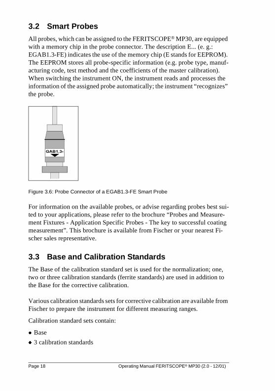
All probes, which can be assigned to the FERITSCOPE® MP30, are equipped with a memory chip in the probe connector. The description E... (e. g.: EGAB1.3-FE) indicates the use of the memory chip (E stands for EEPROM). The EEPROM stores all probe-specific information (e.g. probe type, manuf-acturing code, test method and the coefficients of the master calibration).When switching the instrument ON, the instrument reads and processes the information of the assigned probe automatically; the instrument “recognizes” the probe.
Figure 3.6: Probe Connector of a EGAB1.3-FE Smart Probe
For information on the available probes, or advise regarding probes best sui-ted to your applications, please refer to the brochure “Probes and Measure-ment Fixtures - Application Specific Probes - The key to successful coating measurement”. This brochure is available from Fischer or your nearest Fi-scher sales representative.
3.3 Base and Calibration Standards
The Base of the calibration standard set is used for the normalization; one, two or three calibration standards (ferrite standards) are used in addition to the Base for the corrective calibration.
Various calibration standards sets for corrective calibration are available from Fischer to prepare the instrument for different measuring ranges.
Calibration standard sets contain:
� Base
� 3 calibration standards
Page 18 Operating Manual FERITSCOPE® MP30 (2.0 - 12/01)
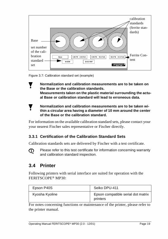
Figure 3.7: Calibration standard set (example)
Normalization and calibration measurements are to be taken on the Base or the calibration standards. Measurements taken on the plastic material surrounding the actu-al Base or calibration standard will lead to erroneous data.
Normalization and calibration measurements are to be taken wi-thin a circular area having a diameter of 10 mm around the center of the Base or the calibration standard.
For information on the available calibration standard sets, please contact your your nearest Fischer sales representative or Fischer directly.
3.3.1 Certification of the Calibration Standard Sets
Calibration standards sets are delivered by Fischer with a test certificate.
Please refer to this test certificate for information concerning warranty and calibration standard inspection.
3.4 Printer
Following printers with serial interface are suited for operation with the FERITSCOPE® MP30:
For notes concerning functions or maintenance of the printer, please refer to the printer manual.
Epson P40S Seiko DPU-411
Kyosha Kyoline Epson compatible serial dot matrix printers
Base
calibration standards(ferrite stan-dards)
Ferrite Con-tent
set numberof the cali-bration standard set
Operating Manual FERITSCOPE® MP30 (2.0 - 12/01) Page 19

Page 20 Operating Manual FERITSCOPE® MP30 (2.0 - 12/01)
4 Switching the Instrument ON and OFF
4.1 Switching the Instrument ON
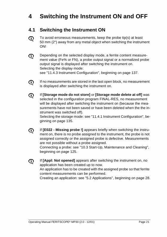
To avoid erroneous measurements, keep the probe tip(s) at least 50 mm (2“) away from any metal object when switching the instrument ON!
Depending on the selected display mode, a ferrite content measure-ment value (Fe% or FN), a probe output signal or a normalized probe output signal is displayed after switching the instrument on.Selecting the display mode: see "11.4.3 Instrument Configuration", beginning on page 137.
If no measurements are stored in the last open block, no measurement is displayed after switching the instrument on.
If [Storage mode do not store] or [Storage mode delete at off] was selected in the configuration program FINAL-RES, no measurement will be displayed after switching the instrument on (because the mea-surements have not been saved or have been deleted when the the in-strument was switched off).Selecting the storage mode: see "11.4.1 Instrument Configuration", be-ginning on page 135.
If [E022 - Missing probe !] appears briefly when switching the instru-ment on, there is no probe assigned to the instrument, the probe is not assigned correctly or the assigned probe is defective. Measurements are not possible without a probe assigned. Connecting a probe: see "10.3 Start-Up, Maintenance and Cleaning", beginning on page 125.
If [Appl: Not opened] appears after switching the instrument on, no application has been created up to now. An application has to be created with the assigned probe so that ferrite content measurements can be performed.Creating an application: see "5.2 Applications", beginning on page 28.
Operating Manual FERITSCOPE® MP30 (2.0 - 12/01) Page 21
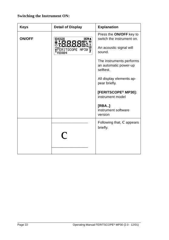
Switching the Instrument ON:
Keys Detail of Display Explanation
ON/OFFPress the ON/OFF key to switch the instrument on.
An acoustic signal will sound.
The instruments performs an automatic power-up selftest.
All display elements ap-pear briefly.
[FERITSCOPE® MP30]:instrument model
[RBA..]:instrument software version
__________________
c__________________
Following that, c appears briefly.
Page 22 Operating Manual FERITSCOPE® MP30 (2.0 - 12/01)
_________________
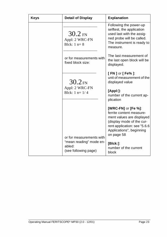
30.2 FN Appl: 2 WRC-FN Blck: 1 n= 8 _________________
or for measurements with fixed block size:
_________________
30.2 FN Appl: 2 WRC-FN Blck: 1 n= 1/ 4__________________
or for measurements with “mean reading” mode en-abled:(see following page)
Following the power-up selftest, the application used last with the assig-ned probe will be called. The instrument is ready to measure.
The last measurement of the last open block will be displayed.
[ FN ] or [ Fe% ]: unit of measurement of the displayed value
[Appl:]: number of the current ap-plication
[WRC-FN] or [Fe %]: ferrite content measure-ment values are displayed (display mode of the cur-rent application: see "5.6.6 Applications", beginning on page 58
[Blck:]: number of the current block
Keys Detail of Display Explanation
Operating Manual FERITSCOPE® MP30 (2.0 - 12/01) Page 23
If [ % ] or [ FN ] flashes, no application has been created with the cur-rently assigned probe. Measurements are not possible with flashing display. An application has to be created with the assigned probe so that ferrite content measurements can be performed. Creating an application: see "5.2 Applications", beginning on page 28.
4.2 Switching the Instrument OFF
Auto switch-off mode The instrument will switch itself off automatically if no measurement is taken and no key is pressed for approximately three minutes.
However, if the auto switch-off mode has been disabled in the configuration programs, the instrument will not switch itself off automatically.
Disable the auto switch-off mode:see "11.4 Instrument Configuration", beginning on page 134
To switch the instrument off manually simply press the ON/OFF key. The display will go blank.
__________________
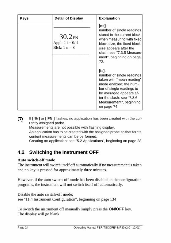
30.2 FN Appl: 2 i = 0/ 4 Blck: 1 n = 8__________________
[n=]: number of single readings stored in the current block; when measuring with fixed block size, the fixed block size appears after the slash: see "7.3.5 Measure-ment", beginning on page 72.
[i=]: number of single readings taken with “mean reading” mode enabled; the num-ber of single readings to be averaged appears af-ter the slash: see "7.3.6 Measurement", beginning on page 74.
Keys Detail of Display Explanation
Page 24 Operating Manual FERITSCOPE® MP30 (2.0 - 12/01)
5 Applications
You can create up to 100 different applications. Up to 10,000 measurements can be stored in these applications. The measurements can be combined into up to 1,000 blocks.
An application contains:
� single readings
� application specific settings
� coefficients determined during normalization and corrective calibration (used for fitting the master calibration curve stored in the memory chip of the probe connector to the current measurement application)
5.1 Selecting the Desired Application
An application has to be selected which was created with the currently assig-ned probe so that measurements can be performed.
If [ NF ] or [ % ] flashes on the display after switching the instrument on or when an application has been selected, it is indicating that no appli-cation has been created with the probe currently being used. Measurements are not possible with flashing display.
If no application has been created with the assigned probe, these are the choices:
� Create a new application with the assigned probe see "5.2 Applications", beginning on page 28
� Overwrite an existing application with the assigned probe see "5.3 Applications", beginning on page 32
� Select an existing application, that has been created for the probe currently in use ; see "10.3 Start-Up, Maintenance and Cleaning", beginning on page 125
Operating Manual FERITSCOPE® MP30 (2.0 - 12/01) Page 25
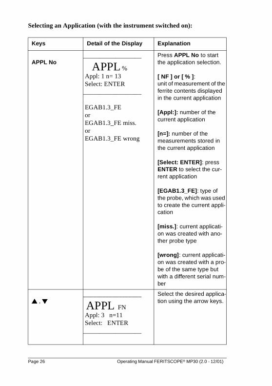
Selecting an Application (with the instrument switched on):
Keys Detail of the Display Explanation
APPL No__________________
APPL % Appl: 1 n= 13 Select: ENTER__________________
EGAB1.3_FE or EGAB1.3_FE miss. or EGAB1.3_FE wrong
Press APPL No to start the application selection.
[ NF ] or [ % ]: unit of measurement of the ferrite contents displayed in the current application
[Appl:]: number of the current application
[n=]: number of the measurements stored in the current application
[Select: ENTER]: press ENTER to select the cur-rent application
[EGAB1.3_FE]: type of the probe, which was used to create the current appli-cation
[miss.]: current applicati-on was created with ano-ther probe type
[wrong]: current applicati-on was created with a pro-be of the same type but with a different serial num-ber
� , �__________________
APPL FN Appl: 3 n=11 Select: ENTER__________________
Select the desired applica-tion using the arrow keys.
Page 26 Operating Manual FERITSCOPE® MP30 (2.0 - 12/01)
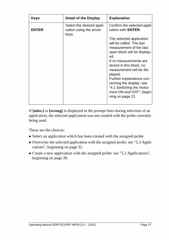
If [miss.] or [wrong] is displayed in the prompt lines during selection of an application, the selected application was not created with the probe currently being used.
These are the choices:
� Select an application which has been created with the assigned probe
� Overwrite the selected application with the assigned probe: see "5.3 Appli-cations", beginning on page 32.
� Create a new application with the assigned probe: see "5.2 Applications", beginning on page 28.
ENTERSelect the desired appli-cation using the arrow keys.
Confirm the selected appli-cation with ENTER.
The selected application will be called. The last measurement of the last open block will be display-ed. If no measurements are stored in this block, no measurement will be dis-played.Further explanations con-cerning the display: see "4.1 Switching the Instru-ment ON and OFF", begin-ning on page 21
Keys Detail of the Display Explanation
Operating Manual FERITSCOPE® MP30 (2.0 - 12/01) Page 27
5.2 Creating an Application
An application has to be created and a probe has to be assigned so that measu-rements can be stored in this application.
The unit of measurement for the ferrite content which are to be taken in the application to be created, can be selected in the configuration program ZERO. Selecting the unit of measurement: see "11.4.3 Instrument Configura-tion", beginning on page 137.If, for instance, ferrite numbers are selected as unit of measurement in the configuration program ZERO, the ferrite content of a newly created application will be displayed in ferrite numbers.
When creating an application with the linking mode enabled (indicated by v in the display), the instrument checks automatically, if one or more applications have been created with the assigned probe.If at least one application has been created with the assigned probe, no normalization is necessary when creating an application. The normalization and cor-rective calibration of the application(s) previously created with this pro-be is used in this case.
With the restricted operating mode enabled (indicated by e in the dis-play), only applications already created can be selected, i. e. new ap-plications cannot be created. Restricted Operating Mode: see "11.3 Instrument Configuration", be-ginning on page 133.
Page 28 Operating Manual FERITSCOPE® MP30 (2.0 - 12/01)
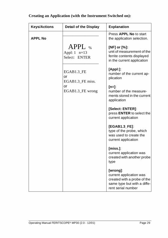
Creating an Application (with the Instrument Switched on):
Keys/Actions Detail of the Display Explanation
APPL No __________________
APPL % Appl: 1 n=13 Select: ENTER__________________
EGAB1.3_FE or EGAB1.3_FE miss. or EGAB1.3_FE wrong
Press APPL No to start the application selection.
[NF] or [%]: unit of measurement of the ferrite contents displayed in the current application
[Appl:]: number of the current ap-plication
[n=]: number of the measure-ments stored in the current application
[Select: ENTER]: press ENTER to select the current application
[EGAB1.3_FE]: type of the probe, which was used to create the current application
[miss.]: current application was created with another probe type
[wrong]: current application was created with a probe of the same type but with a diffe-rent serial number
Operating Manual FERITSCOPE® MP30 (2.0 - 12/01) Page 29
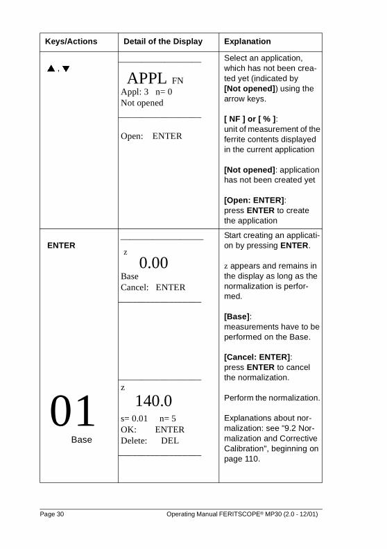
� , �
__________________
APPL FN Appl: 3 n= 0 Not opened__________________
Open: ENTER
Select an application, which has not been crea-ted yet (indicated by [Not opened]) using the arrow keys.
[ NF ] or [ % ]: unit of measurement of the ferrite contents displayed in the current application
[Not opened]: application has not been created yet
[Open: ENTER]: press ENTER to create the application
ENTER
0 1Base
__________________
z 0.00 Base Cancel: ENTER__________________
__________________ z
140.0 s= 0.01 n= 5 OK: ENTER Delete: DEL__________________
Start creating an applicati-on by pressing ENTER.
z appears and remains in the display as long as the normalization is perfor-med.
[Base]: measurements have to be performed on the Base.
[Cancel: ENTER]: press ENTER to cancel the normalization.
Perform the normalization.
Explanations about nor-malization: see "9.2 Nor-malization and Corrective Calibration", beginning on page 110.
Keys/Actions Detail of the Display Explanation
Page 30 Operating Manual FERITSCOPE® MP30 (2.0 - 12/01)
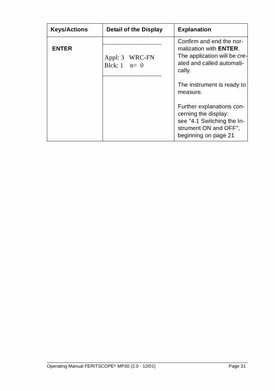
ENTER __________________
Appl: 3 WRC-FN Blck: 1 n= 0__________________
Confirm and end the nor-malization with ENTER. The application will be cre-ated and called automati-cally.
The instrument is ready to measure.
Further explanations con-cerning the display: see "4.1 Switching the In-strument ON and OFF", beginning on page 21
Keys/Actions Detail of the Display Explanation
Operating Manual FERITSCOPE® MP30 (2.0 - 12/01) Page 31
5.3 Overwriting an Application
An existing application can be overwritten by connecting a different probe and performing a normalization with this probe, if it is no longer needed.
When overwriting an application with the linking mode enabled (indica-ted by v in the display), the normalizations of all applications linked to the current application will also be overwritten automatically.
With the restricted operating mode enabled (indicated by e in the dis-play), the key ZERO is not active, i. e. applications cannot be overwrit-ten.Restricted Operating Mode: see "11.3 Instrument Configuration", be-ginning on page 133
Page 32 Operating Manual FERITSCOPE® MP30 (2.0 - 12/01)
Overwriting an Application (with the instrument switched on):
Keys/Actions Detail of the Display Explanation
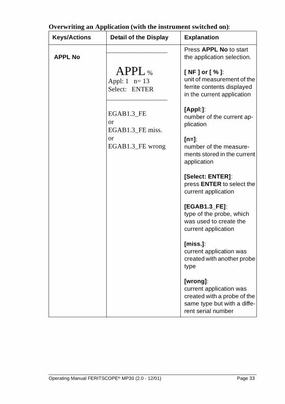
APPL No__________________
APPL % Appl: 1 n= 13 Select: ENTER__________________
EGAB1.3_FE or EGAB1.3_FE miss. or EGAB1.3_FE wrong
Press APPL No to start the application selection.
[ NF ] or [ % ]: unit of measurement of the ferrite contents displayed in the current application
[Appl:]: number of the current ap-plication
[n=]: number of the measure-ments stored in the current application
[Select: ENTER]: press ENTER to select the current application
[EGAB1.3_FE]: type of the probe, which was used to create the current application
[miss.]: current application was created with another probe type
[wrong]: current application was created with a probe of the same type but with a diffe-rent serial number
Operating Manual FERITSCOPE® MP30 (2.0 - 12/01) Page 33
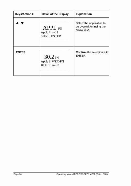
� , �__________________
APPL FN Appl: 3 n=11 Select: ENTER__________________
Select the application to be overwritten using the arrow keys.
ENTER __________________
30.2 FN Appl: 3 WRC-FN Blck: 1 n= 11__________________
Confirm the selection with ENTER.
Keys/Actions Detail of the Display Explanation
Page 34 Operating Manual FERITSCOPE® MP30 (2.0 - 12/01)
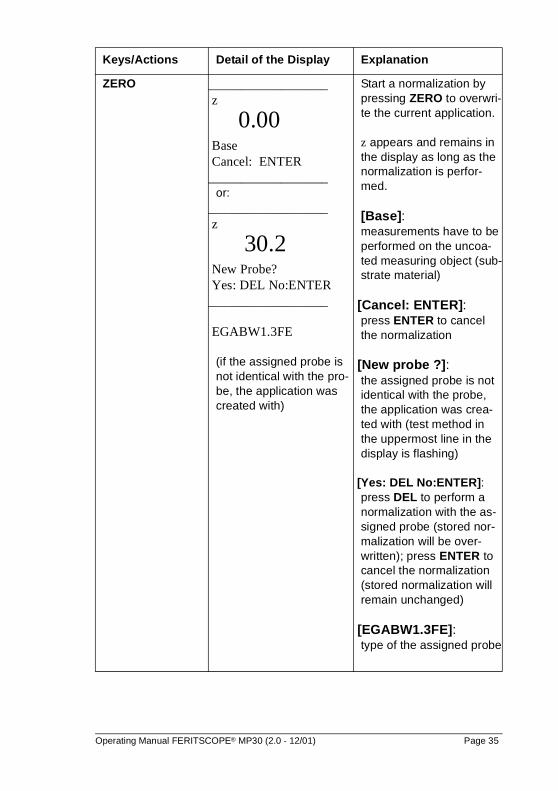
ZERO __________________ z
0.00 Base Cancel: ENTER__________________
or:__________________ z
30.2 New Probe? Yes: DEL No:ENTER__________________
EGABW1.3FE
(if the assigned probe is not identical with the pro-be, the application was created with)
Start a normalization by pressing ZERO to overwri-te the current application.
z appears and remains in the display as long as the normalization is perfor-med.
[Base]: measurements have to be performed on the uncoa-ted measuring object (sub-strate material)
[Cancel: ENTER]:press ENTER to cancel the normalization
[New probe ?]: the assigned probe is not identical with the probe, the application was crea-ted with (test method in the uppermost line in the display is flashing)
[Yes: DEL No:ENTER]:press DEL to perform a normalization with the as-signed probe (stored nor-malization will be over-written); press ENTER to cancel the normalization (stored normalization will remain unchanged)
[EGABW1.3FE]: type of the assigned probe
Keys/Actions Detail of the Display Explanation
Operating Manual FERITSCOPE® MP30 (2.0 - 12/01) Page 35
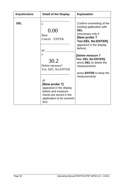
DEL __________________ z
0.00 Base Cancel: ENTER__________________ or: __________________ z
30.2 Delete measure? Yes: DEL No:ENTER__________________
(if [New probe ?]
appeared in the display before and measure-ments are stored in the application to be overwrit-ten)
Confirm overwriting of the existing application with DEL (necessary only if
[New probe ? Yes:DEL No:ENTER]
appeared in the display before).
[Delete measure ? Yes: DEL No:ENTER]:
press DEL to delete the measurements
press ENTER to keep the measurements
Keys/Actions Detail of the Display Explanation
Page 36 Operating Manual FERITSCOPE® MP30 (2.0 - 12/01)
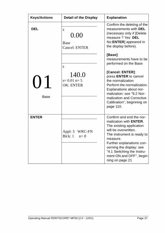
DEL
0 1 Base
__________________ z
0.00 Base Cancel: ENTER__________________
__________________ z
140.0 s= 0.01 n= 5 OK: ENTER
__________________
Confirm the deleting of the measurements with DEL (necessary only if [Delete measure ? Yes: DEL No:ENTER] appeared in the display before).
[Base]: measurements have to be performed on the Base
[Cancel: ENTER]: press ENTER to cancel the normalizationPerform the normalization. Explanations about nor-malization: see "9.2 Nor-malization and Corrective Calibration", beginning on page 110.
ENTER __________________
Appl: 3 WRC-FN Blck: 1 n= 0__________________
Confirm and end the nor-malization with ENTER. The existing application will be overwritten. The instrument is ready to measure. Further explanations con-cerning the display: see "4.1 Switching the Instru-ment ON and OFF", begin-ning on page 21
Keys/Actions Detail of the Display Explanation
Operating Manual FERITSCOPE® MP30 (2.0 - 12/01) Page 37
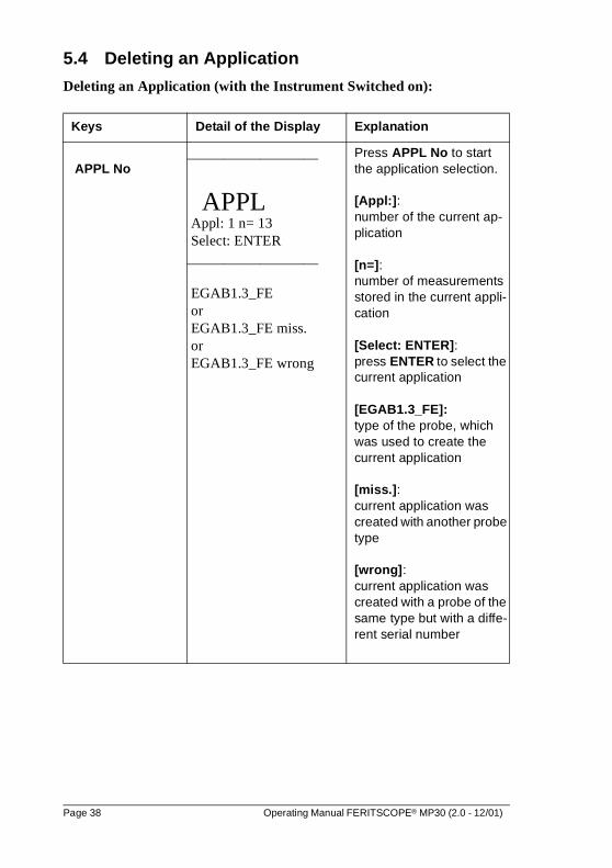
5.4 Deleting an Application
Deleting an Application (with the Instrument Switched on):
Keys Detail of the Display Explanation
APPL No __________________
APPL Appl: 1 n= 13 Select: ENTER__________________
EGAB1.3_FE or EGAB1.3_FE miss. or EGAB1.3_FE wrong
Press APPL No to start the application selection.
[Appl:]: number of the current ap-plication
[n=]:number of measurements stored in the current appli-cation
[Select: ENTER]: press ENTER to select the current application
[EGAB1.3_FE]:type of the probe, which was used to create the current application
[miss.]: current application was created with another probe type
[wrong]: current application was created with a probe of the same type but with a diffe-rent serial number
Page 38 Operating Manual FERITSCOPE® MP30 (2.0 - 12/01)
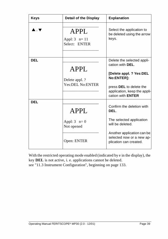
With the restricted operating mode enabled (indicated by e in the display), the key DEL is not active, i. e. applications cannot be deleted.see "11.3 Instrument Configuration", beginning on page 133.
� , �__________________
APPL Appl: 3 n= 11 Select: ENTER__________________
Select the application to be deleted using the arrow keys.
DEL __________________
APPL Delete appl. ? Yes:DEL No:ENTER__________________
Delete the selected appli-cation with DEL.
[Delete appl. ? Yes:DEL No:ENTER]:
press DEL to delete the application, keep the appli-cation with ENTER
DEL __________________
APPL Appl: 3 n= 0 Not opened__________________
Open: ENTER
Confirm the deletion with DEL.
The selected application will be deleted.
Another application can be selected now or a new ap-plication can created.
Keys Detail of the Display Explanation
Operating Manual FERITSCOPE® MP30 (2.0 - 12/01) Page 39
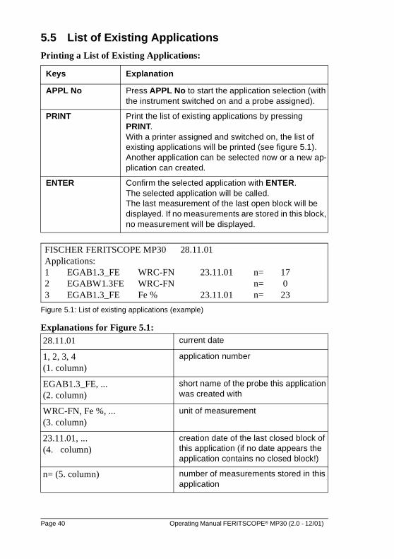
5.5 List of Existing Applications
Printing a List of Existing Applications:
Figure 5.1: List of existing applications (example)
Explanations for Figure 5.1:
Keys Explanation
APPL No Press APPL No to start the application selection (with the instrument switched on and a probe assigned).
PRINT Print the list of existing applications by pressing PRINT. With a printer assigned and switched on, the list of existing applications will be printed (see figure 5.1).Another application can be selected now or a new ap-plication can created.
ENTER Confirm the selected application with ENTER.The selected application will be called. The last measurement of the last open block will be displayed. If no measurements are stored in this block, no measurement will be displayed.
28.11.01 current date
1, 2, 3, 4 (1. column)
application number
EGAB1.3_FE, ... (2. column)
short name of the probe this application was created with
WRC-FN, Fe %, ... (3. column)
unit of measurement
23.11.01, ... (4. column)
creation date of the last closed block of this application (if no date appears the application contains no closed block!)
n= (5. column) number of measurements stored in this application
FISCHER FERITSCOPE MP30 28.11.01Applications:1 EGAB1.3_FE WRC-FN 23.11.01 n= 172 EGABW1.3FE WRC-FN n= 03 EGAB1.3_FE Fe % 23.11.01 n= 23
Page 40 Operating Manual FERITSCOPE® MP30 (2.0 - 12/01)
5.6 Application-Specific Settings
The following settings are valid only for the current application, i. e. they are application-specific:
� settings made with the MENU key
� display mode; see "5.6.6 Applications", beginning on page 58.
� unit of measurement; see "11.4.7 Instrument Configuration", beginning on page 145.
After pressing the key MENU the following application-specific settings can be changed:
� specification limits monitoring
� display resolution
� automatic block formation and block size
� number of single readings, which have to be taken before the actual measurement is computed as mean value of these single readings
� outlier rejection
The procedure after pressing the key MENU may be terminated at any time by pressing MENU again.
During the procedure after pressing the key MENU the record of the in-strument status can be printed or displayed at any time by pressing the key PRINT see "11.5 Instrument Configuration", beginning on page 148.
With the restricted operating mode enabled (indicated by e in the dis-play), the key MENU is not active, i. e. the application-specific settings cannot be changed! Restricted Operating Mode: see "11.3 Instrument Configuration", be-ginning on page 133.
Operating Manual FERITSCOPE® MP30 (2.0 - 12/01) Page 41
Page 42 Operating Manual FERITSCOPE® MP30 (2.0 - 12/01)
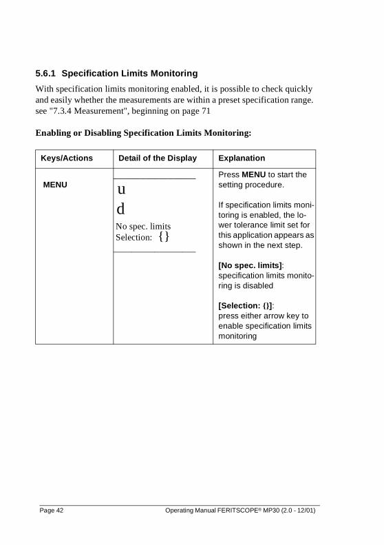
5.6.1 Specification Limits Monitoring
With specification limits monitoring enabled, it is possible to check quickly and easily whether the measurements are within a preset specification range. see "7.3.4 Measurement", beginning on page 71
Enabling or Disabling Specification Limits Monitoring:
Keys/Actions Detail of the Display Explanation
MENU__________________
u d No spec. limits Selection: {}__________________
Press MENU to start the setting procedure.
If specification limits moni-toring is enabled, the lo-wer tolerance limit set for this application appears as shown in the next step.
[No spec. limits]: specification limits monito-ring is disabled
[Selection: {}]: press either arrow key to enable specification limits monitoring
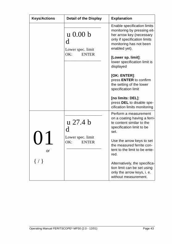
__________________ u 0.00 b d Lower spec. limit OK: ENTER__________________
Enable specification limits monitoring by pressing eit-her arrow key (necessary only if specification limits monitoring has not been enabled yet).
[Lower sp. limit]: lower specification limit is displayed
[OK: ENTER]:press ENTER to confirm the setting of the lower specification limit
[no limits: DEL]: press DEL to disable spe-cification limits monitoring
0 1or
{ / }
__________________ u 27.4 b d Lower spec. limit OK: ENTER
_________________
Perform a measurement on a coating having a ferri-te content similar to the specification limit to be set.
Use the arrow keys to set the measured ferrite con-tent to the limit to be ente-red.
Alternatively, the specifica-tion limit can be set using only the arrow keys, i. e. without measurement.
Keys/Actions Detail of the Display Explanation
Operating Manual FERITSCOPE® MP30 (2.0 - 12/01) Page 43
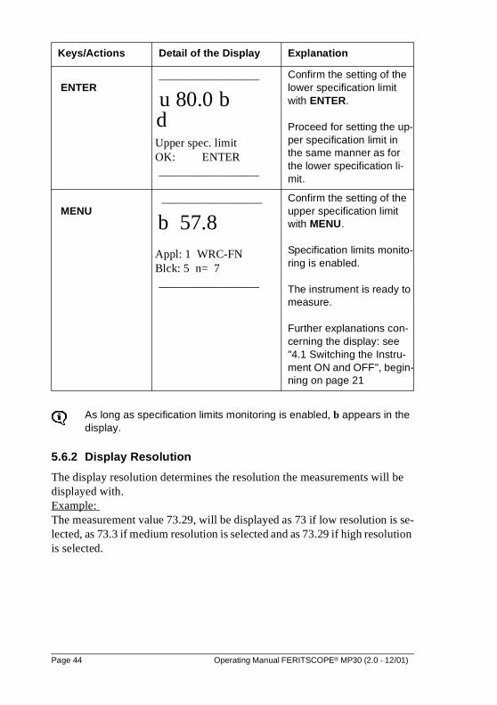
As long as specification limits monitoring is enabled, b appears in the display.
5.6.2 Display Resolution
The display resolution determines the resolution the measurements will be displayed with. Example: The measurement value 73.29, will be displayed as 73 if low resolution is se-lected, as 73.3 if medium resolution is selected and as 73.29 if high resolution is selected.
ENTER_________________
u 80.0 b d Upper spec. limit OK: ENTER
_________________
Confirm the setting of the lower specification limit with ENTER.
Proceed for setting the up-per specification limit in the same manner as for the lower specification li-mit.
MENU _________________
b 57.8 Appl: 1 WRC-FN Blck: 5 n= 7
_________________
Confirm the setting of the upper specification limit with MENU.
Specification limits monito-ring is enabled.
The instrument is ready to measure.
Further explanations con-cerning the display: see "4.1 Switching the Instru-ment ON and OFF", begin-ning on page 21
Keys/Actions Detail of the Display Explanation
Page 44 Operating Manual FERITSCOPE® MP30 (2.0 - 12/01)
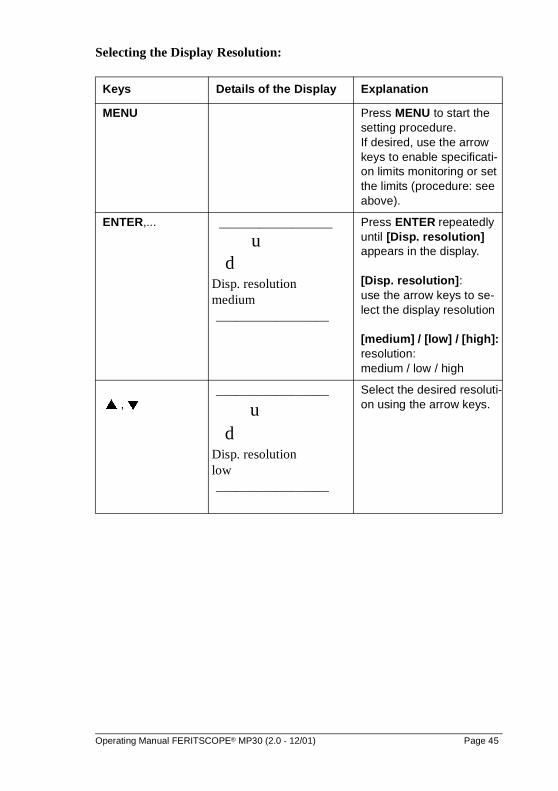
Selecting the Display Resolution:
Keys Details of the Display Explanation
MENU Press MENU to start the setting procedure. If desired, use the arrow keys to enable specificati-on limits monitoring or set the limits (procedure: see above).
ENTER,... _________________
u d
Disp. resolution medium
_________________
Press ENTER repeatedly until [Disp. resolution] appears in the display.
[Disp. resolution]: use the arrow keys to se-lect the display resolution
[medium] / [low] / [high]: resolution: medium / low / high
� , �_________________
u d
Disp. resolution low
_________________
Select the desired resoluti-on using the arrow keys.
Operating Manual FERITSCOPE® MP30 (2.0 - 12/01) Page 45
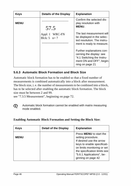
5.6.3 Automatic Block Formation and Block Size
Automatic block formation has to be enabled so that a fixed number of measurements is combined automatically into a block after measurement. The block size, i. e. the number of measurements to be combined into a block, has to be selected after enabling the automatic block formation. The block size must be between 2 and 99. see "7.3.5 Measurement", beginning on page 72.
Automatic block formation cannot be enabled with matrix measuring mode enabled.
Enabling Automatic Block Formation and Setting the Block Size:
MENU_________________
57.5 Appl: 1 WRC-FN Blck: 5 n= 7
_________________
Confirm the selected dis-play resolution with MENU.
The last measurement will be displayed in the selec-ted resolution. The instru-ment is ready to measure.
Further explanations con-cerning the display: see "4.1 Switching the Instru-ment ON and OFF", begin-ning on page 21
Keys Detail of the Display Explanation
MENUPress MENU to start the setting procedure. If desired use the arrow keys to enable specificati-on limits monitoring or set the specification limits see "5.6.1 Applications", be-ginning on page 42
Keys Details of the Display Explanation
Page 46 Operating Manual FERITSCOPE® MP30 (2.0 - 12/01)
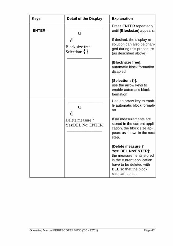
ENTER,... _________________
u d
Block size free Selection: {}
_________________
Press ENTER repeatedly until [Blocksize] appears. If desired, the display re-solution can also be chan-ged during this procedure (as described above).
[Block size free]: automatic block formation disabled
[Selection: {}]: use the arrow keys to enable automatic block formation
_________________
u d
Delete measure ? Yes:DEL No: ENTER
_________________
Use an arrow key to enab-le automatic block formati-on.
If no measurements are stored in the current appli-cation, the block size ap-pears as shown in the next step.
[Delete measure ? Yes: DEL No:ENTER]: the measurements stored in the current application have to be deleted with DEL so that the block size can be set
Keys Detail of the Display Explanation
Operating Manual FERITSCOPE® MP30 (2.0 - 12/01) Page 47
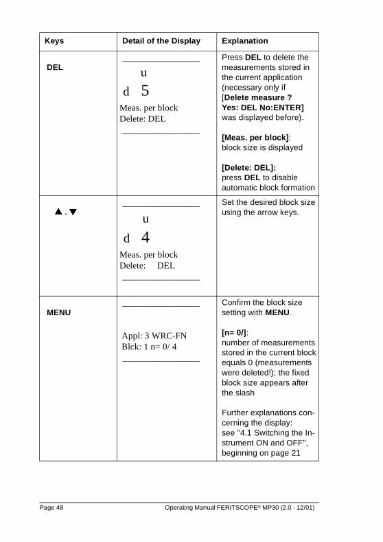
DEL _________________
u
d 5 Meas. per block Delete: DEL
_________________
Press DEL to delete the measurements stored in the current application (necessary only if [Delete measure ? Yes: DEL No:ENTER] was displayed before).
[Meas. per block]: block size is displayed
[Delete: DEL]: press DEL to disable automatic block formation
� , �_________________
u
d 4 Meas. per block Delete: DEL
_________________
Set the desired block size using the arrow keys.
MENU _________________
Appl: 3 WRC-FN Blck: 1 n= 0/ 4
_________________
Confirm the block size setting with MENU.
[n= 0/]: number of measurements stored in the current block equals 0 (measurements were deleted!); the fixed block size appears after the slash
Further explanations con-cerning the display: see "4.1 Switching the In-strument ON and OFF", beginning on page 21
Keys Detail of the Display Explanation
Page 48 Operating Manual FERITSCOPE® MP30 (2.0 - 12/01)
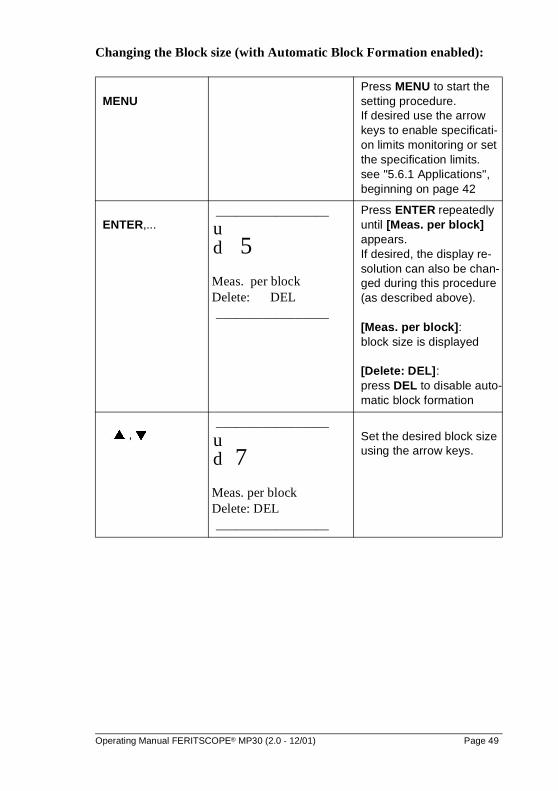
Changing the Block size (with Automatic Block Formation enabled):
MENUPress MENU to start the setting procedure. If desired use the arrow keys to enable specificati-on limits monitoring or set the specification limits.see "5.6.1 Applications", beginning on page 42
ENTER,..._________________
u d 5 Meas. per block Delete: DEL
_________________
Press ENTER repeatedly until [Meas. per block] appears. If desired, the display re-solution can also be chan-ged during this procedure (as described above).
[Meas. per block]: block size is displayed
[Delete: DEL]: press DEL to disable auto-matic block formation
� , �_________________
u d 7 Meas. per block Delete: DEL
_________________
Set the desired block size using the arrow keys.
Operating Manual FERITSCOPE® MP30 (2.0 - 12/01) Page 49
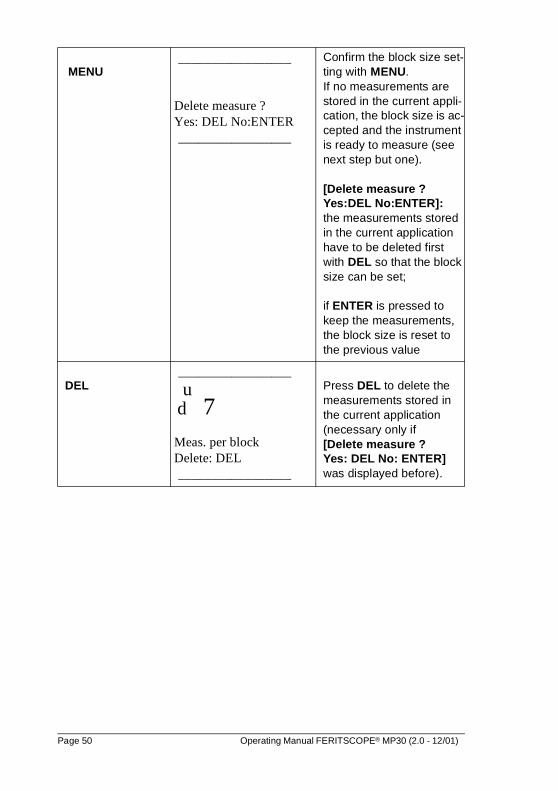
MENU_________________
Delete measure ? Yes: DEL No:ENTER
_________________
Confirm the block size set-ting with MENU. If no measurements are stored in the current appli-cation, the block size is ac-cepted and the instrument is ready to measure (see next step but one).
[Delete measure ? Yes:DEL No:ENTER]: the measurements stored in the current application have to be deleted first with DEL so that the block size can be set;
if ENTER is pressed to keep the measurements, the block size is reset to the previous value
DEL_________________
u d 7 Meas. per block Delete: DEL
_________________
Press DEL to delete the measurements stored in the current application (necessary only if [Delete measure ? Yes: DEL No: ENTER] was displayed before).
Page 50 Operating Manual FERITSCOPE® MP30 (2.0 - 12/01)
Disabling Automatic Block Formation:
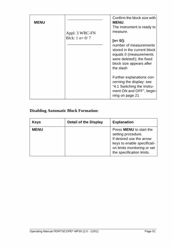
MENU_________________
Appl: 3 WRC-FN Blck: 1 n= 0/ 7
_________________
Confirm the block size with MENU. The instrument is ready to measure.
[n= 0/]:number of measurements stored in the current block equals 0 (measurements were deleted!); the fixed block size appears after the slash
Further explanations con-cerning the display: see "4.1 Switching the Instru-ment ON and OFF", begin-ning on page 21
Keys Detail of the Display Explanation
MENU Press MENU to start the setting procedure. If desired use the arrow keys to enable specificati-on limits monitoring or set the specification limits.
Operating Manual FERITSCOPE® MP30 (2.0 - 12/01) Page 51
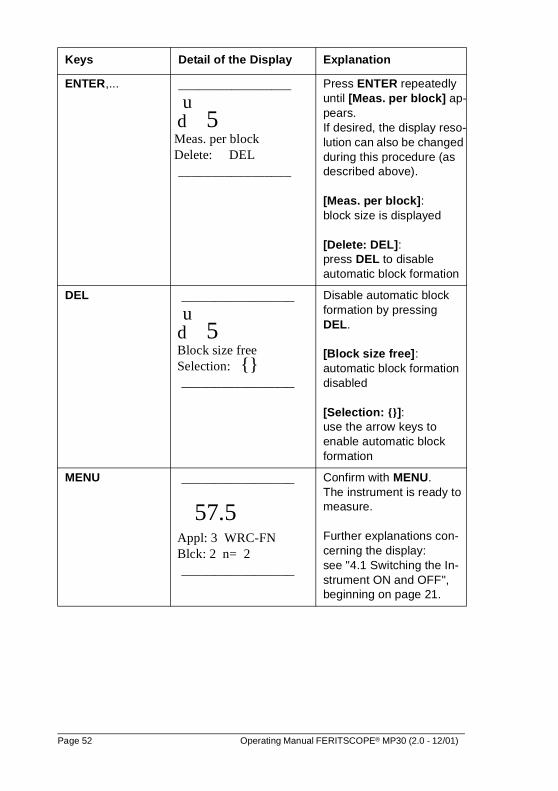
ENTER,... _________________
u d 5 Meas. per block Delete: DEL
_________________
Press ENTER repeatedly until [Meas. per block] ap-pears.If desired, the display reso-lution can also be changed during this procedure (as described above).
[Meas. per block]: block size is displayed
[Delete: DEL]: press DEL to disable automatic block formation
DEL _________________
u d 5 Block size free Selection: {}
_________________
Disable automatic block formation by pressing DEL.
[Block size free]: automatic block formation disabled
[Selection: {}]: use the arrow keys to enable automatic block formation
MENU _________________
57.5 Appl: 3 WRC-FN Blck: 2 n= 2
_________________
Confirm with MENU. The instrument is ready to measure.
Further explanations con-cerning the display: see "4.1 Switching the In-strument ON and OFF", beginning on page 21.
Keys Detail of the Display Explanation
Page 52 Operating Manual FERITSCOPE® MP30 (2.0 - 12/01)
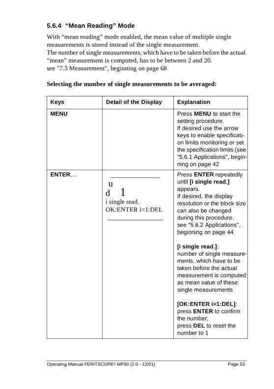
5.6.4 “Mean Reading” Mode
With “mean reading” mode enabled, the mean value of multiple single measurements is stored instead of the single measurement. The number of single measurements, which have to be taken before the actual “mean” measurement is computed, has to be between 2 and 20.see "7.3 Measurement", beginning on page 68
Selecting the number of single measurements to be averaged:
Keys Detail of the Display Explanation
MENU Press MENU to start the setting procedure. If desired use the arrow keys to enable specificati-on limits monitoring or set the specification limits (see "5.6.1 Applications", begin-ning on page 42
ENTER,... _______________
u d 1 i single read. OK:ENTER i=1:DEL
_________________
Press ENTER repeatedly until [i single read.] appears. If desired, the display resolution or the block size can also be changed during this procedure. see "5.6.2 Applications", beginning on page 44
[i single read.]: number of single measure-ments, which have to be taken before the actual measurement is computed as mean value of these single measurements
[OK:ENTER i=1:DEL]: press ENTER to confirm the number; press DEL to reset the number to 1
Operating Manual FERITSCOPE® MP30 (2.0 - 12/01) Page 53
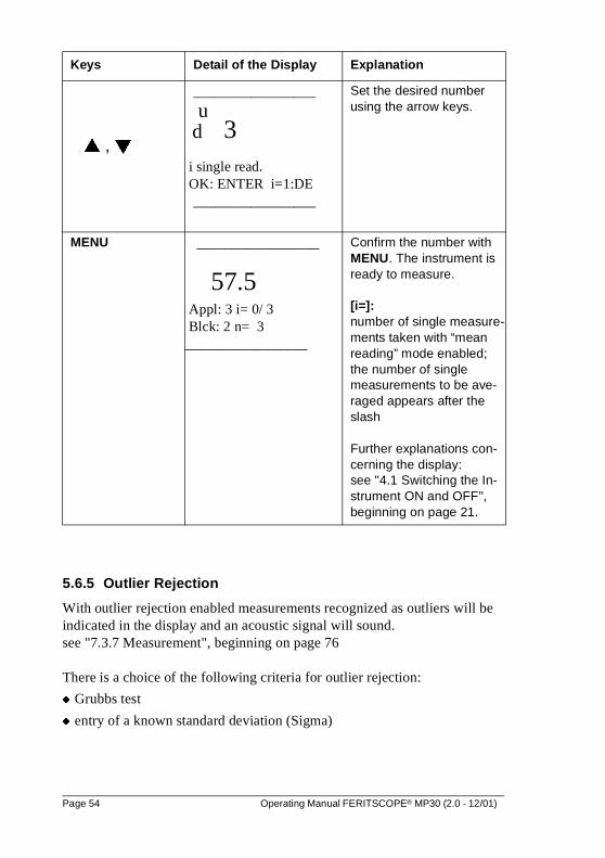
5.6.5 Outlier Rejection
With outlier rejection enabled measurements recognized as outliers will be indicated in the display and an acoustic signal will sound.see "7.3.7 Measurement", beginning on page 76
There is a choice of the following criteria for outlier rejection:
� Grubbs test
� entry of a known standard deviation (Sigma)
� , �
_________________
u d 3 i single read. OK: ENTER i=1:DE
_________________
Set the desired number using the arrow keys.
MENU _________________
57.5 Appl: 3 i= 0/ 3 Blck: 2 n= 3 _________________
Confirm the number with MENU. The instrument is ready to measure.
[i=]: number of single measure-ments taken with “mean reading” mode enabled; the number of single measurements to be ave-raged appears after the slash
Further explanations con-cerning the display: see "4.1 Switching the In-strument ON and OFF", beginning on page 21.
Keys Detail of the Display Explanation
Page 54 Operating Manual FERITSCOPE® MP30 (2.0 - 12/01)
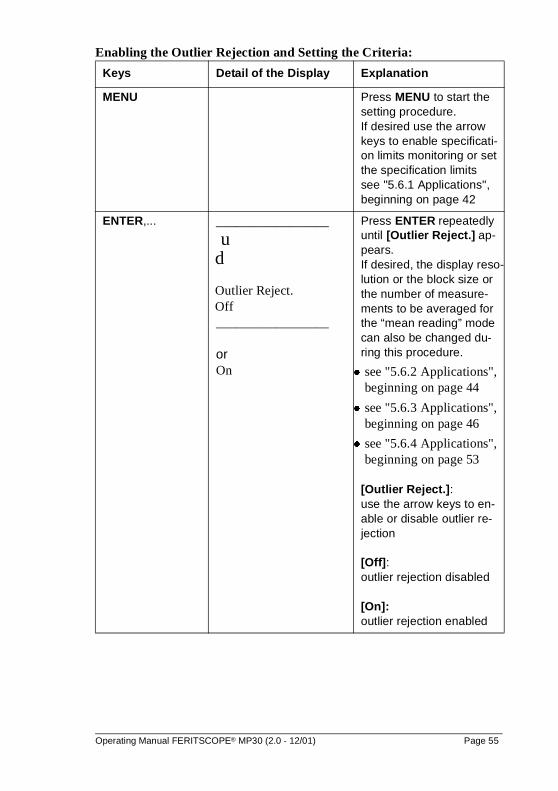
Enabling the Outlier Rejection and Setting the Criteria:
Keys Detail of the Display Explanation
MENU Press MENU to start the setting procedure.If desired use the arrow keys to enable specificati-on limits monitoring or set the specification limitssee "5.6.1 Applications", beginning on page 42
ENTER,... _________________
u d
Outlier Reject. Off
_________________
orOn
Press ENTER repeatedly until [Outlier Reject.] ap-pears. If desired, the display reso-lution or the block size or the number of measure-ments to be averaged for the “mean reading” mode can also be changed du-ring this procedure.
� see "5.6.2 Applications", beginning on page 44
� see "5.6.3 Applications", beginning on page 46
� see "5.6.4 Applications", beginning on page 53
[Outlier Reject.]: use the arrow keys to en-able or disable outlier re-jection
[Off]: outlier rejection disabled
[On]: outlier rejection enabled
Operating Manual FERITSCOPE® MP30 (2.0 - 12/01) Page 55
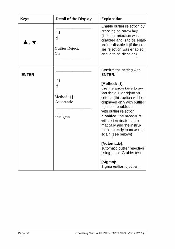
� , �
_________________
u d
Outlier Reject. On
_________________
Enable outlier rejection by pressing an arrow key (if outlier rejection was disabled and is to be enab-led) or disable it (if the out-lier rejection was enabled and is to be disabled).
ENTER_________________
u d
Method: {} Automatic
_________________
or Sigma
Confirm the setting with ENTER.
[Method: {}]: use the arrow keys to se-lect the outlier rejection criteria (this option will be displayed only with outlier rejection enabled; with outlier rejection disabled, the procedure will be terminated auto-matically and the instru-ment is ready to measure again (see below))
[Automatic]: automatic outlier rejection using to the Grubbs test
[Sigma]: Sigma outlier rejection
Keys Detail of the Display Explanation
Page 56 Operating Manual FERITSCOPE® MP30 (2.0 - 12/01)
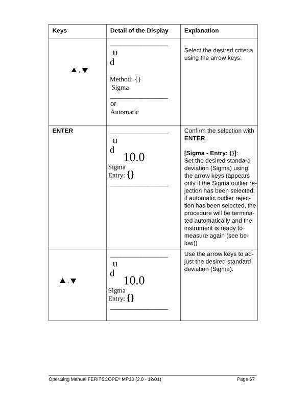
� , �
_________________
u d
Method: {} Sigma
_________________or Automatic
Select the desired criteria using the arrow keys.
ENTER _________________
u d 10.0 Sigma Entry: {}
_________________
Confirm the selection with ENTER.
[Sigma - Entry: {}]: Set the desired standard deviation (Sigma) using the arrow keys (appears only if the Sigma outlier re-jection has been selected; if automatic outlier rejec-tion has been selected, the procedure will be termina-ted automatically and the instrument is ready to measure again (see be-low))
� , �
_________________
u d 10.0 Sigma Entry: {}
_________________
Use the arrow keys to ad-just the desired standard deviation (Sigma).
Keys Detail of the Display Explanation
Operating Manual FERITSCOPE® MP30 (2.0 - 12/01) Page 57
5.6.6 Display Modes
The following display modes can be selected according to table 5.1Selecting the display mode:see "11.4.3 Instrument Configuration", beginning on page 137.
� Display Ferrite Content (WRC-FN or Fe%)
� Display Xn and Xs
� Display Ferrite Content Fe and Xs
� Display Countrate
� Display Normalized Countrate
The display mode can be set separately for each application. The set-ting of the display mode of the other applications remains unchanged.
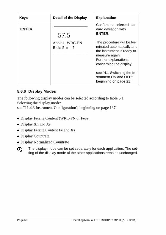
ENTER _________________
57.5 Appl: 1 WRC-FN Blck: 5 n= 7
_________________
Confirm the selected stan-dard deviation with ENTER.
The procedure will be ter-minated automatically and the instrument is ready to measure again.Further explanations concerning the display:
see "4.1 Switching the In-strument ON and OFF", beginning on page 21
Keys Detail of the Display Explanation
Page 58 Operating Manual FERITSCOPE® MP30 (2.0 - 12/01)
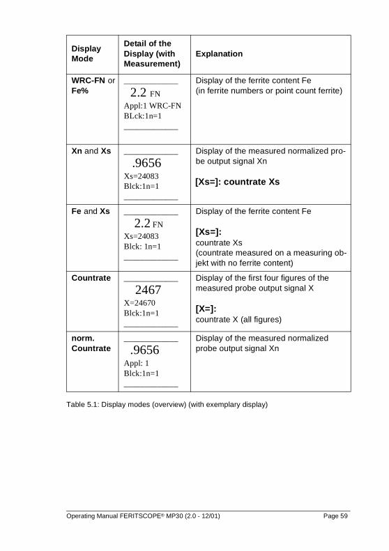
Table 5.1: Display modes (overview) (with exemplary display)
Display Mode
Detail of the Display (with Measurement)
Explanation
WRC-FN or Fe%
_____________
2.2 FN
Appl:1 WRC-FNBLck:1n=1_____________
Display of the ferrite content Fe(in ferrite numbers or point count ferrite)
Xn and Xs _____________
.9656Xs=24083Blck:1n=1_____________
Display of the measured normalized pro-be output signal Xn
[Xs=]: countrate Xs
Fe and Xs _____________
2.2 FN
Xs=24083Blck: 1n=1_____________
Display of the ferrite content Fe
[Xs=]: countrate Xs (countrate measured on a measuring ob-jekt with no ferrite content)
Countrate _____________
2467X=24670Blck:1n=1_____________
Display of the first four figures of the measured probe output signal X
[X=]:countrate X (all figures)
norm. Countrate
_____________
.9656Appl: 1Blck:1n=1_____________
Display of the measured normalizedprobe output signal Xn
Operating Manual FERITSCOPE® MP30 (2.0 - 12/01) Page 59
5.7 Linking the Applications
With linking mode enabled all applications created with the very same probe (having the same serial number) are linked with respect to normalization and calibration. The same normalization and corrective calibration is used for the computation of the measurement values in linked applications.
As an example, if separate applications were created to measure different bat-ches of the same part, it would make sense to link these applications. By lin-king all applications share the same corrective calibration and normalization.
A normalization or calibration performed in any of the linked applications will be effective for all of the linked applications. The normalization or calibration stored in these applications will be overwrit-ten.
To ensure that the linked applications use the same normalization and calibration, perform a normalization and calibration in any of these lin-ked applications.
Applications created with different probes of the same probe type (ha-ving the same probe type but different serial numbers) cannot be lin-ked!
5.7.1 Enabling or Disabling the Linking Mode
The linking mode can be enabled or disabled only in the configuration pro-gram APPL No.see "11.4.7 Instrument Configuration", beginning on page 145.
As long as the linking mode is enabled, v will be displayed.
After disabling the linking mode, the applications become independent again! Every application can be normalized or calibrated separately again.
Page 60 Operating Manual FERITSCOPE® MP30 (2.0 - 12/01)
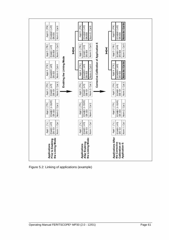
Figure 5.2: Linking of applications (example)
Operating Manual FERITSCOPE® MP30 (2.0 - 12/01) Page 61
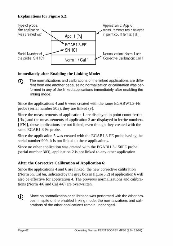
Explanations for Figure 5.2:
Immediately after Enabling the Linking Mode:
The normalizations and calibrations of the linked applications are diffe-rent from one another because no normalization or calibration was per-formed in any of the linked applications immediately after enabling the linking mode.
Since the applications 4 and 6 were created with the same EGABW1.3-FE probe (serial number 505), they are linked (v).
Since the measurements of application 1 are displayed in point count ferrite [ % ] and the measurements of application 3 are displayed in ferrite numbers [ FN ], these applications are not linked, even though they created with the same EGAB1.3-Fe probe.
Since the application 5 was created with the EGAB1.3-FE probe having the serial number 909, it is not linked to these applications.
Since no other application was created with the EGABI1.3-150FE probe (serial number 303), application 2 is not linked to any other application.
After the Corrective Calibration of Application 6:
Since the applications 4 and 6 are linked, the new corrective calibration (Norm 6n, Cal 6n, indicated by the grey box in figure 5.2) of application 6 will also be effective for application 4. The previous normalizations and calibra-tions (Norm 4/6 and Cal 4/6) are overwritten.
Since no normalization or calibration was performed with the other pro-bes, in spite of the enabled linking mode, the normalizations and cali-brations of the other applications remain unchanged.
Page 62 Operating Manual FERITSCOPE® MP30 (2.0 - 12/01)
6 Standard and Matrix Measuring Mode
The following measuring modes are available:
� standard measuring mode
� matrix measuring mode
6.1 Standard Measuring Mode
With the standard measuring mode enabled single measurements are taken consecutively on the same part, for example on a board, and are then combi-ned by pressing BLOCK-RES into a block. The resulting block mean value then represents the local ferrite content of the reference area.
With the standard measuring mode enabled, measurements can only be stored in the last open block of an application.The applications can contain different numbers of blocks. Each block can store a different number of measurements.
However, if automatic block formation has been enabled, only blocks with fixed block size can be formed.
Enable automatic block formation and selecting the block size: see "5.6.3 Applications", beginning on page 46
Measurement with fixed block size:see "7.3.5 Measurement", beginning on page 72
Operating Manual FERITSCOPE® MP30 (2.0 - 12/01) Page 63
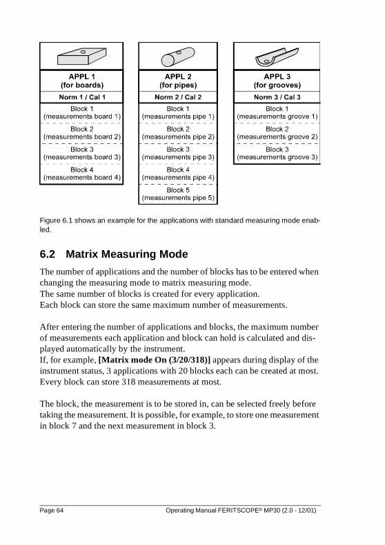
Figure 6.1 shows an example for the applications with standard measuring mode enab-led.
6.2 Matrix Measuring Mode
The number of applications and the number of blocks has to be entered when changing the measuring mode to matrix measuring mode. The same number of blocks is created for every application. Each block can store the same maximum number of measurements.
After entering the number of applications and blocks, the maximum number of measurements each application and block can hold is calculated and dis-played automatically by the instrument. If, for example, [Matrix mode On (3/20/318)] appears during display of the instrument status, 3 applications with 20 blocks each can be created at most. Every block can store 318 measurements at most.
The block, the measurement is to be stored in, can be selected freely before taking the measurement. It is possible, for example, to store one measurement in block 7 and the next measurement in block 3.
Page 64 Operating Manual FERITSCOPE® MP30 (2.0 - 12/01)
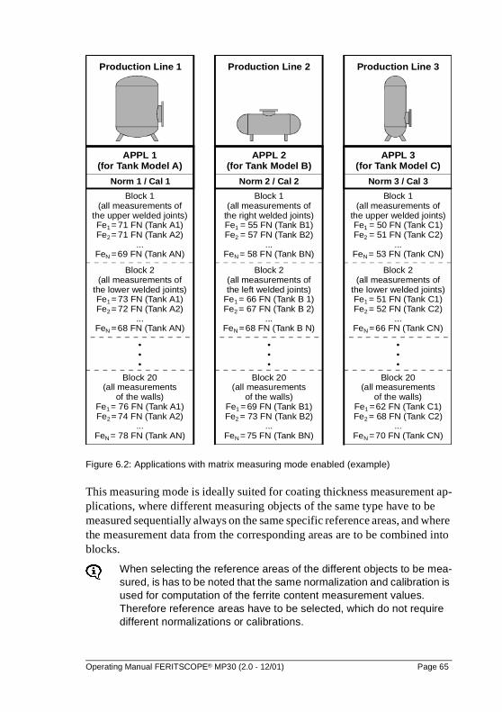
Figure 6.2: Applications with matrix measuring mode enabled (example)
This measuring mode is ideally suited for coating thickness measurement ap-plications, where different measuring objects of the same type have to be measured sequentially always on the same specific reference areas, and where the measurement data from the corresponding areas are to be combined into blocks.
When selecting the reference areas of the different objects to be mea-sured, is has to be noted that the same normalization and calibration is used for computation of the ferrite content measurement values. Therefore reference areas have to be selected, which do not require different normalizations or calibrations.
Norm 2 / Cal 2 Norm 3 / Cal 3
APPL 2(for Tank Model B)
APPL 3(for Tank Model C)
Block 1(all measurements of
the right welded joints)Fe = 55 FN (Tank B1)Fe = 57 FN (Tank B2)
...Fe = 58 FN (Tank BN)
1
2
N
Block 1(all measurements of
the upper welded joints)Fe = 50 FN (Tank C1)Fe = 51 FN (Tank C2)
...Fe = 53 FN (Tank CN)
1
2
N
Block 2(all measurements ofthe left welded joints)
Fe = 66 FN (Tank B 1)Fe = 67 FN (Tank B 2)
...Fe =68 FN (Tank B N)
1
2
N
Block 2(all measurements of
the lower welded joints)Fe = 51 FN (Tank C1)Fe = 52 FN (Tank C2)
...Fe =66 FN (Tank CN)
1
2
N
•••
•••
Block 20(all measurements
of the walls)Fe = 69 FN (Tank B1)Fe = 73 FN (Tank B2)
...Fe = 75 FN (Tank BN)
1
2
N
Block 20(all measurements
of the walls)Fe =62 FN (Tank C1)Fe = 68 FN (Tank C2)
...Fe =70 FN (Tank CN)
1
2
N
Production Line 2 Production Line 3
Norm 1 / Cal 1
APPL 1(for Tank Model A)
Production Line 1
Block 1(all measurements of
the upper welded joints)Fe = 71 FN (Tank A1)Fe = 71 FN (Tank A2)
...Fe =69 FN (Tank AN)
1
2
N
Block 2(all measurements of
the lower welded joints)Fe = 73 FN (Tank A1)Fe = 72 FN (Tank A2)
...Fe =68 FN (Tank AN)
1
2
N
•••
Block 20(all measurements
of the walls)Fe = 76 FN (Tank A1)Fe = 74 FN (Tank A2)
...Fe = 78 FN (Tank AN)
1
2
N
Operating Manual FERITSCOPE® MP30 (2.0 - 12/01) Page 65
The number of applications or blocks cannot be changed again after-wards without re-initializating the instrument.
The matrix measuring mode is indicated by m in the display.
With matrix measuring mode enabled, automatic block formation cannot be enabled! Accordingly it is not possible to set a block size for the automatic block formation after pressing MENU to change the ap-plication-specific settings.see "5.6 Applications", beginning on page 41
6.3 Changing the Measuring Mode
The measuring mode can be changed only in the configuration program APPL No (see "11.4.7 Instrument Configuration", beginning on page 145).
The instrument will be re-initialized automatically when changing the measuring mode. When re-initializing the instrument, all applications as well as all mea-surements stored will be deleted; the parameters of the configurations programs will be reset to the default settings.After re-initialization, i. e. as well after changing the measuring mode, the required applications have to be created again and the parameters of the configuration programs have to be adjusted to the required set-tings again!
Page 66 Operating Manual FERITSCOPE® MP30 (2.0 - 12/01)
7 Measurement
It is absolutely necessary to follow the instructions of the chapter -> see "2 Notes Concerning the Operation of the Instrument and Hand-ling the Accessories", beginning on page 5!
7.1 Preparations for Measurement
Instrument and measuring area have to be prepared as follows:
� Determination of the significant surface and the reference area according to / 8 /.
� Making sure, that the reference area is not damaged and clean (e.g. free of fluids, dirt or grease).
� Perform the instrument start-up (see "10.1 Start-Up, Maintenance and Cleaning", beginning on page 123).
� Connect the printer and switch the printer on if necessary (if printer is available and printout of the measurements desired).
� Switch the instrument on (see "4.1 Switching the Instrument ON and OFF", beginning on page 21) and select an application that fits the current measuring objectsee "5 Applications", beginning on page 25.
� Check the normalization and calibration by reference measurement on an object with known ferrite content. see "9.1 Normalization and Corrective Calibration", beginning on page 110.
� Check whether a correction factor has to be taken into consideration.see "7.2 Measurement", beginning on page 68.
� Definition of the instrument configuration see "11 Instrument Configuration", beginning on page 129) and of the application-specific settings see "5.6 Applications", beginning on page 41).
Operating Manual FERITSCOPE® MP30 (2.0 - 12/01) Page 67
7.2 Influencing Factors
The following factors affect the ferrite content measurement with the FERITSCOPE® MP30:
� curvature of the measuring object
� thickness of the measuring object
� layer thickness
� distance of the measuring position to the edge
The effects of these factors can be corrected for by multiplying the measured ferrite content with the corresponding correction factors see "15 Correction Factors", beginning on page 169.
Generally, a correction of these influences is required only if:
� the diameter of the curvature is smaller than 50 mm (2") (for measuring objects with convex curvature) or smaller than 80 mm (3.2") (for measuring objects with concave curvature), or
� the thickness of the measuring object is smaller than 2 mm (80 mils), or
� the layer thickness is smaller than 2 mm (80 mils), or
� the distance of the measuring position to the edge is smaller than 2 mm (80 mils).
7.3 Making a Measurement
The probe has to be placed vertically on the surface of the measuring object to perform a measurement. The measurements should be performed within the reference area.
Following the measurement accept, i. e. after the measurement appears in the display, the probe can be lifted again. The instrument is ready to measure again.
Page 68 Operating Manual FERITSCOPE® MP30 (2.0 - 12/01)
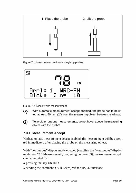
Figure 7.1: Measurement with axial single tip probes
Figure 7.2: Display with measurement
With automatic measurement accept enabled, the probe has to be lif-ted at least 50 mm (2") from the measuring object between readings.
To avoid erroneous measurements, do not hover above the measuring object with the probe!
7.3.1 Measurement Accept
With automatic measurement accept enabled, the measurement will be accep-ted immediately after placing the probe on the measuring object.
With “continuous” display mode enabled (enabling the “continuous” display mode: see "7.6 Measurement", beginning on page 83), measurement accept can be initiated by:
� pressing the key ENTER
� sending the command G0 (G Zero) via the RS232 interface
1. Place the probe 2. Lift the probe
Operating Manual FERITSCOPE® MP30 (2.0 - 12/01) Page 69
7.3.2 Measurements with External Start Enabled
If automatic measurement accept is not desired, e. g. for measurement inside pipes, bores or grooves, measurements should be performed with external start enabled and with automatic measurement accept disabled.
The external start feature allows measurement accept by pressing the key �
or by sending the command G0 (G Zero) via the RS232 interface.
Enable external start and disable automatic measurement accept:see "11.4.3 Instrument Configuration", beginning on page 137.
There are several ways to initiate measurement accept manually with external start enabled after placing the probe on the measuring area:
� pressing the key �
� sending the command G0 (G Zero) via the RS232 interface
During normalization or corrective calibration, a measurement can be initia-ted with external start enabled by:
� pressing the key FINAL-RES
� sending the command G0 (G Zero) via the RS232 interface
7.3.3 Acoustic Signals after Measurement Accept
An acoustic signal will sound with every measurement taken (unless it is disabled) after measurement accept. The signal indicates that the measurement signal coming from the probe is captured and the probe may be lifted off from the measuring object again.
Enable and disable the acoustic measurement accept signal:see "11.1 Instrument Configuration", beginning on page 129.
In addition to the acoustic measurement accept signal, the acoustic signals lis-ted in table 7.1 may sound. If applicable, the signals will sound in succession. If, for example, the last measurement of a block has violated the upper speci-fication limit when measuring with fixed block size, the acoustic measure-ment accept signal will sound followed by two short signals to indicate the violation of the upper specification limit and at last one long signal to indicate the closing of the block.
Page 70 Operating Manual FERITSCOPE® MP30 (2.0 - 12/01)
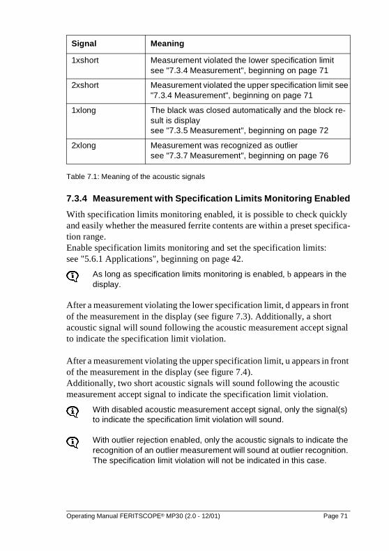
Table 7.1: Meaning of the acoustic signals
7.3.4 Measurement with Specification Limits Monitoring Enabled
With specification limits monitoring enabled, it is possible to check quickly and easily whether the measured ferrite contents are within a preset specifica-tion range. Enable specification limits monitoring and set the specification limits: see "5.6.1 Applications", beginning on page 42.
As long as specification limits monitoring is enabled, b appears in the display.
After a measurement violating the lower specification limit, d appears in front of the measurement in the display (see figure 7.3). Additionally, a short acoustic signal will sound following the acoustic measurement accept signal to indicate the specification limit violation.
After a measurement violating the upper specification limit, u appears in front of the measurement in the display (see figure 7.4). Additionally, two short acoustic signals will sound following the acoustic measurement accept signal to indicate the specification limit violation.
With disabled acoustic measurement accept signal, only the signal(s) to indicate the specification limit violation will sound.
With outlier rejection enabled, only the acoustic signals to indicate the recognition of an outlier measurement will sound at outlier recognition. The specification limit violation will not be indicated in this case.
Signal Meaning
1xshort Measurement violated the lower specification limitsee "7.3.4 Measurement", beginning on page 71
2xshort Measurement violated the upper specification limit see "7.3.4 Measurement", beginning on page 71
1xlong The black was closed automatically and the block re-sult is display see "7.3.5 Measurement", beginning on page 72
2xlong Measurement was recognized as outlier see "7.3.7 Measurement", beginning on page 76
Operating Manual FERITSCOPE® MP30 (2.0 - 12/01) Page 71
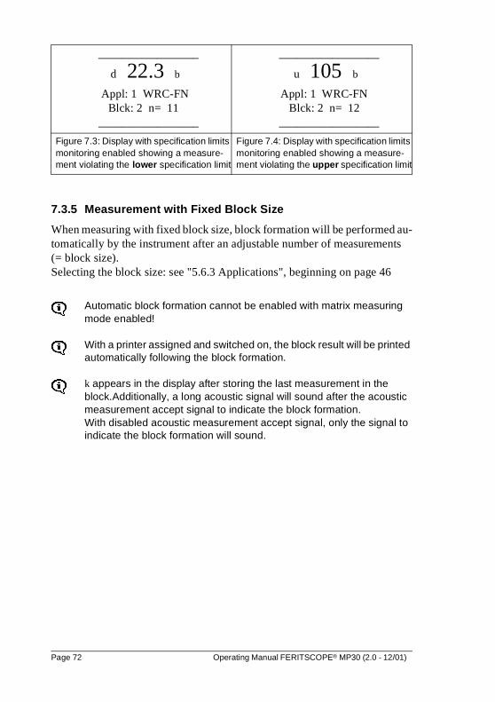
7.3.5 Measurement with Fixed Block Size
When measuring with fixed block size, block formation will be performed au-tomatically by the instrument after an adjustable number of measurements (= block size). Selecting the block size: see "5.6.3 Applications", beginning on page 46
Automatic block formation cannot be enabled with matrix measuring mode enabled!
With a printer assigned and switched on, the block result will be printed automatically following the block formation.
k appears in the display after storing the last measurement in the block.Additionally, a long acoustic signal will sound after the acoustic measurement accept signal to indicate the block formation.With disabled acoustic measurement accept signal, only the signal to indicate the block formation will sound.
_________________
d 22.3 b
Appl: 1 WRC-FNBlck: 2 n= 11
_________________
_________________
u 105 b
Appl: 1 WRC-FNBlck: 2 n= 12
_________________
Figure 7.3: Display with specification limits monitoring enabled showing a measure-ment violating the lower specification limit
Figure 7.4: Display with specification limits monitoring enabled showing a measure-ment violating the upper specification limit
Page 72 Operating Manual FERITSCOPE® MP30 (2.0 - 12/01)
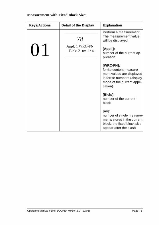
Measurement with Fixed Block Size:
Keys/Actions Detail of the Display Explanation
0 1 _________________
78 Appl: 1 WRC-FN Blck: 2 n= 1/ 4
_________________
Perform a measurement. The measurement value will be displayed.
[Appl:]: number of the current ap-plication
[WRC-FN]: ferrite content measure-ment values are displayed in ferrite numbers (display mode of the current appli-cation)
[Blck:]: number of the current block
[n=]: number of single measure-ments stored in the current block; the fixed block size appear after the slash
Operating Manual FERITSCOPE® MP30 (2.0 - 12/01) Page 73
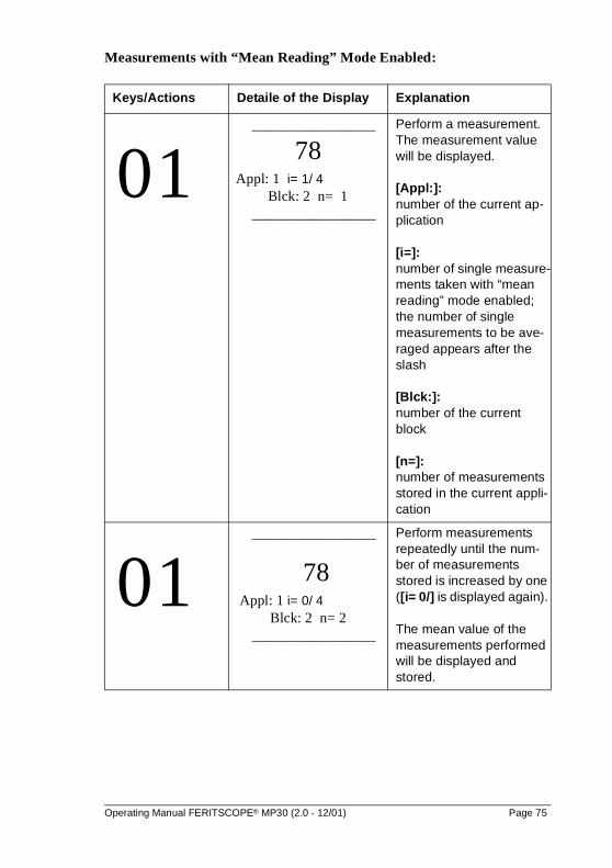
7.3.6 Measurement with “Mean Reading” Mode Enabled
When measuring with “mean reading” mode enabled, the mean value of mul-tiple single measurements (i single readings) is stored instead of the single measurement. This mode is especially well suited for rough surfaces.(Selec-ting the number of single measurements, which have to be taken before the actual measurement is computed as mean value of these single measure-ments: see "5.6.4 Applications", beginning on page 53
With “mean reading” mode and outlier rejection enabled, single mea-surements recognized as outliers are not included in the computation of the actual measurement!
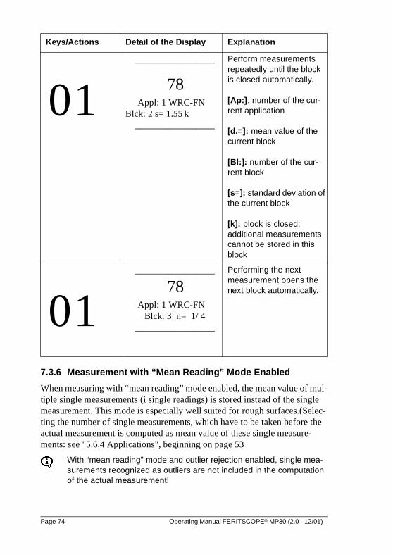
0 1 _________________
78 Appl: 1 WRC-FN
Blck: 2 s= 1.55 k _________________
Perform measurements repeatedly until the block is closed automatically.
[Ap:]: number of the cur-rent application
[d.=]: mean value of the current block
[Bl:]: number of the cur-rent block
[s=]: standard deviation of the current block
[k]: block is closed; additional measurements cannot be stored in this block
0 1 _________________
78 Appl: 1 WRC-FN Blck: 3 n= 1/ 4
_________________
Performing the next measurement opens the next block automatically.
Keys/Actions Detail of the Display Explanation
Page 74 Operating Manual FERITSCOPE® MP30 (2.0 - 12/01)
Measurements with “Mean Reading” Mode Enabled:
Keys/Actions Detaile of the Display Explanation
0 1 _________________
78 Appl: 1 i= 1/ 4
Blck: 2 n= 1 _________________
Perform a measurement. The measurement value will be displayed.
[Appl:]: number of the current ap-plication
[i=]: number of single measure-ments taken with “mean reading” mode enabled; the number of single measurements to be ave-raged appears after the slash
[Blck:]: number of the current block
[n=]: number of measurements stored in the current appli-cation
0 1 _________________
78 Appl: 1 i= 0/ 4
Blck: 2 n= 2 _________________
Perform measurements repeatedly until the num-ber of measurements stored is increased by one ([i= 0/] is displayed again).
The mean value of the measurements performed will be displayed and stored.
Operating Manual FERITSCOPE® MP30 (2.0 - 12/01) Page 75
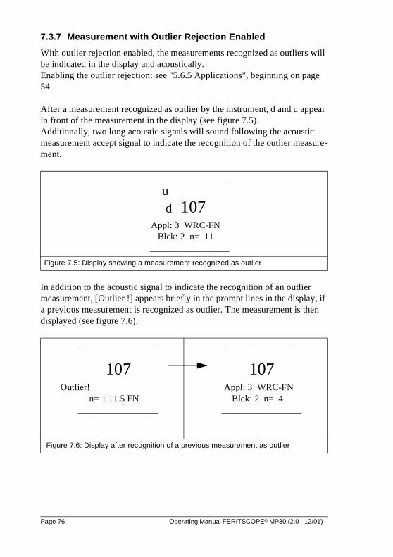
7.3.7 Measurement with Outlier Rejection Enabled
With outlier rejection enabled, the measurements recognized as outliers will be indicated in the display and acoustically. Enabling the outlier rejection: see "5.6.5 Applications", beginning on page 54.
After a measurement recognized as outlier by the instrument, d and u appear in front of the measurement in the display (see figure 7.5). Additionally, two long acoustic signals will sound following the acoustic measurement accept signal to indicate the recognition of the outlier measure-ment.
In addition to the acoustic signal to indicate the recognition of an outlier measurement, [Outlier !] appears briefly in the prompt lines in the display, if a previous measurement is recognized as outlier. The measurement is then displayed (see figure 7.6).
________________
ud 107
Appl: 3 WRC-FNBlck: 2 n= 11
_________________
Figure 7.5: Display showing a measurement recognized as outlier
________________
107 Outlier!
n= 1 11.5 FN _________________
________________
107 Appl: 3 WRC-FN
Blck: 2 n= 4 _________________
Figure 7.6: Display after recognition of a previous measurement as outlier
Page 76 Operating Manual FERITSCOPE® MP30 (2.0 - 12/01)
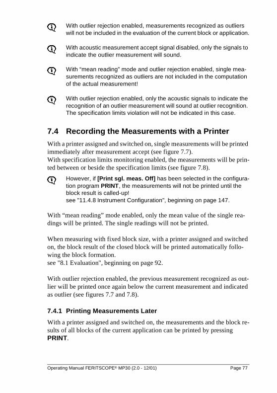
With outlier rejection enabled, measurements recognized as outliers will not be included in the evaluation of the current block or application.
With acoustic measurement accept signal disabled, only the signals to indicate the outlier measurement will sound.
With “mean reading” mode and outlier rejection enabled, single mea-surements recognized as outliers are not included in the computation of the actual measurement!
With outlier rejection enabled, only the acoustic signals to indicate the recognition of an outlier measurement will sound at outlier recognition. The specification limits violation will not be indicated in this case.
7.4 Recording the Measurements with a Printer
With a printer assigned and switched on, single measurements will be printed immediately after measurement accept (see figure 7.7).With specification limits monitoring enabled, the measurements will be prin-ted between or beside the specification limits (see figure 7.8).
However, if [Print sgl. meas. Off] has been selected in the configura-tion program PRINT, the measurements will not be printed until the block result is called-up! see "11.4.8 Instrument Configuration", beginning on page 147.
With “mean reading” mode enabled, only the mean value of the single rea-dings will be printed. The single readings will not be printed.
When measuring with fixed block size, with a printer assigned and switched on, the block result of the closed block will be printed automatically follo-wing the block formation.see "8.1 Evaluation", beginning on page 92.
With outlier rejection enabled, the previous measurement recognized as out-lier will be printed once again below the current measurement and indicated as outlier (see figures 7.7 and 7.8).
7.4.1 Printing Measurements Later
With a printer assigned and switched on, the measurements and the block re-sults of all blocks of the current application can be printed by pressing PRINT.
Operating Manual FERITSCOPE® MP30 (2.0 - 12/01) Page 77
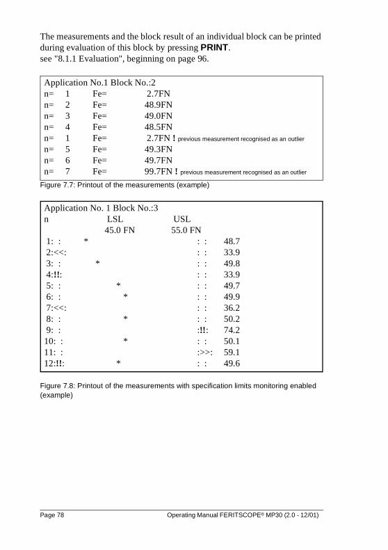
The measurements and the block result of an individual block can be printed during evaluation of this block by pressing PRINT. see "8.1.1 Evaluation", beginning on page 96.
Figure 7.7: Printout of the measurements (example)
Figure 7.8: Printout of the measurements with specification limits monitoring enabled (example)
Application No.1 Block No.:2n= 1 Fe= 2.7FNn= 2 Fe= 48.9FNn= 3 Fe= 49.0FNn= 4 Fe= 48.5FNn= 1 Fe= 2.7FN ! previous measurement recognised as an outlier
n= 5 Fe= 49.3FNn= 6 Fe= 49.7FNn= 7 Fe= 99.7FN ! previous measurement recognised as an outlier
Application No. 1 Block No.:3n LSL USL
45.0 FN 55.0 FN 1: : * : : 48.7 2:<<: : : 33.9 3: : * : : 49.8 4:!!: : : 33.9 5: : * : : 49.7 6: : * : : 49.9 7:<<: : : 36.2 8: : * : : 50.2 9: : :!!: 74.210: : * : : 50.111: : :>>: 59.112:!!: * : : 49.6
Page 78 Operating Manual FERITSCOPE® MP30 (2.0 - 12/01)
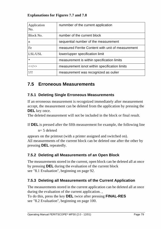
Explanations for Figures 7.7 and 7.8
7.5 Erroneous Measurements
7.5.1 Deleting Single Erroneous Measurements
If an erroneous measurement is recognized immediately after measurement accept, the measurement can be deleted from the application by pressing the DEL key once.The deleted measurement will not be included in the block or final result.
If DEL is pressed after the fifth measurement for example, the following line
n= 5 deleted
appears on the printout (with a printer assigned and switched on).All measurements of the current block can be deleted one after the other by pressing DEL repeatedly.
7.5.2 Deleting all Measurements of an Open Block
The measurements stored in the current, open block can be deleted all at once by pressing DEL during the evaluation of the current blocksee "8.1 Evaluation", beginning on page 92.
7.5.3 Deleting all Measurements of the Current Application
The measurements stored in the current application can be deleted all at once during the evaluation of the current application. ,To do this, press the key DEL twice after pressing FINAL-RESsee "8.2 Evaluation", beginning on page 100.
Application No.
nummber of the current application
Block No. number of the current block
n sequential number of the measurement
Fe measured Ferrite Content with unit of measurement
LSL/USL lower/upper specification limit
* measurement is within specification limits
<</>> measurement isnot within specification limits
!/!! measurement was recognized as oulier
Operating Manual FERITSCOPE® MP30 (2.0 - 12/01) Page 79
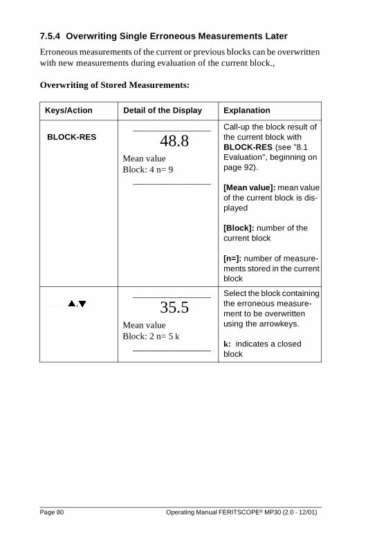
7.5.4 Overwriting Single Erroneous Measurements Later
Erroneous measurements of the current or previous blocks can be overwritten with new measurements during evaluation of the current block.,
Overwriting of Stored Measurements:
Keys/Action Detail of the Display Explanation
BLOCK-RES _________________
48.8 Mean value Block: 4 n= 9
_________________
Call-up the block result of the current block with BLOCK-RES (see "8.1 Evaluation", beginning on page 92).
[Mean value]: mean value of the current block is dis-played
[Block]: number of the current block
[n=]: number of measure-ments stored in the current block
�,� _________________
35.5 Mean value Block: 2 n= 5 k
_________________
Select the block containing the erroneous measure-ment to be overwritten using the arrowkeys.
k: indicates a closed block
Page 80 Operating Manual FERITSCOPE® MP30 (2.0 - 12/01)
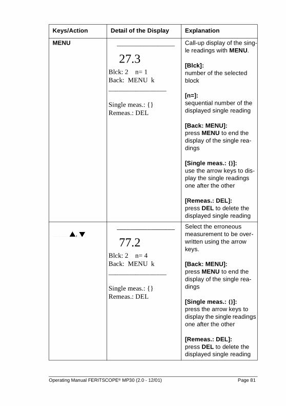
MENU _________________
27.3 Blck: 2 n= 1 Back: MENU k _________________
Single meas.: {} Remeas.: DEL
Call-up display of the sing-le readings with MENU.
[Blck]: number of the selected block
[n=]: sequential number of the displayed single reading
[Back: MENU]: press MENU to end the display of the single rea-dings
[Single meas.: {}]: use the arrow keys to dis-play the single readings one after the other
[Remeas.: DEL]: press DEL to delete the displayed single reading
�, �_________________
77.2 Blck: 2 n= 4 Back: MENU k _________________
Single meas.: {} Remeas.: DEL
Select the erroneous measurement to be over-written using the arrow keys.
[Back: MENU]: press MENU to end the display of the single rea-dings
[Single meas.: {}]: press the arrow keys to display the single readings one after the other
[Remeas.: DEL]: press DEL to delete the displayed single reading
Keys/Action Detail of the Display Explanation
Operating Manual FERITSCOPE® MP30 (2.0 - 12/01) Page 81
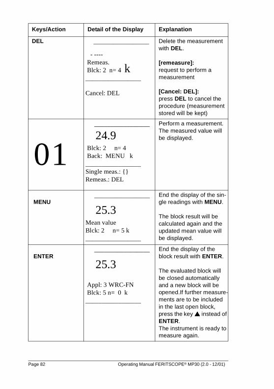
DEL _________________
- ---- Remeas. Blck: 2 n= 4 k _________________
Cancel: DEL
Delete the measurement with DEL.
[remeasure]: request to perform a measurement
[Cancel: DEL]: press DEL to cancel the procedure (measurement stored will be kept)
0 1 _________________
24.9 Blck: 2 n= 4 Back: MENU k _________________ Single meas.: {} Remeas.: DEL
Perform a measurement. The measured value will be displayed.
MENU _________________
25.3 Mean value Blck: 2 n= 5 k _________________
End the display of the sin-gle readings with MENU.
The block result will be calculated again and the updated mean value will be displayed.
ENTER _________________
25.3
Appl: 3 WRC-FN Blck: 5 n= 0 k _________________
End the display of the block result with ENTER.
The evaluated block will be closed automatically and a new block will be opened.If further measure-ments are to be included in the last open block, press the key � instead of ENTER.The instrument is ready to measure again.
Keys/Action Detail of the Display Explanation
Page 82 Operating Manual FERITSCOPE® MP30 (2.0 - 12/01)
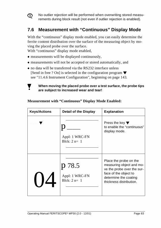
No outlier rejection will be performed when overwriting stored measu-rements during block result (not even if outlier rejection is enabled).
7.6 Measurement with “Continuous” Display Mode
With the “continuous” display mode enabled, you can easily determine the ferrite content distribution over the surface of the measuring object by mo-ving the placed probe over the surface.With “continuous” display mode enabled,
� measurements will be displayed continuously,
� measurements will not be accepted or stored automatically, and
� no data will be transferred via the RS232 interface unless [Send in free ? On] is selected in the configuration program � see "11.4.6 Instrument Configuration", beginning on page 143.
When moving the placed probe over a test surface, the probe tips are subject to increased wear and tear!
Measurement with “Continuous” Display Mode Enabled:
Keys/Actions Detail of the Display Explanation
�
_________________
p _____ Appl: 1 WRC-FN Blck: 2 n= 1
_________________
Press the key �to enable the “continuous” display mode.
04
_________________
p 78.5 Appl: 1 WRC-FN Blck: 2 n= 1
_________________
Place the probe on the measuring object and mo-ve the probe over the sur-face of the object to determine the coating thickness distribution.
Operating Manual FERITSCOPE® MP30 (2.0 - 12/01) Page 83
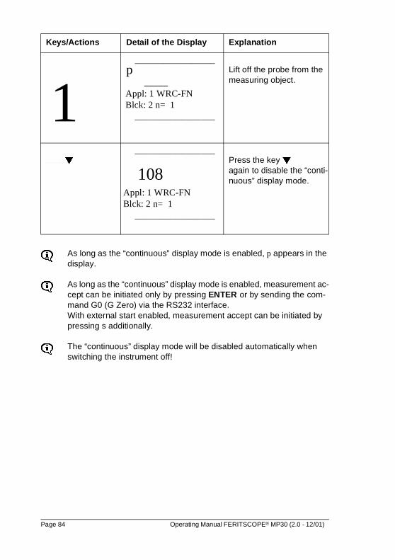
As long as the “continuous” display mode is enabled, p appears in the display.
As long as the “continuous” display mode is enabled, measurement ac-cept can be initiated only by pressing ENTER or by sending the com-mand G0 (G Zero) via the RS232 interface. With external start enabled, measurement accept can be initiated by pressing s additionally.
The “continuous” display mode will be disabled automatically when switching the instrument off!
1_________________
p _____ Appl: 1 WRC-FN Blck: 2 n= 1
_________________
Lift off the probe from the measuring object.
�
_________________
108 Appl: 1 WRC-FN Blck: 2 n= 1
_________________
Press the key �again to disable the “conti-nuous” display mode.
Keys/Actions Detail of the Display Explanation
Page 84 Operating Manual FERITSCOPE® MP30 (2.0 - 12/01)
7.7 Measurement with Standard or Matrix Measuring Mode Enabled
The preparations necessary for measurement and the making of a measure-ment are independent of the measuring mode selected and can be taken from the chapters “see "7.1 Measurement", beginning on page 67 and see "7.3 Measurement", beginning on page 68.Detailed information about the standard and matrix measuring mode:see "6 Standard and Matrix Measuring Mode", beginning on page 63.
The measuring mode can be changed only in the configuration program APPL No (see "11.4.7 Instrument Configuration", beginning on page 145).
7.7.1 Measurement with Standard Measuring Mode Enabled
When measuring with standard measuring mode enabled, the measurements can be stored only in the last open block.
It is not possible, to select the block the next measurement is to be stored in freely.
7.7.2 Measurement with Matrix Measuring Mode Enabled
The matrix measuring mode is indicated by m in the display.
When measuring with matrix measuring mode enabled, the block, the measu-rement is to be stored in, can be selected freely before measuring.It is possible, for example, to store one measurement in block 20 and the next measurement in block 26.
Operating Manual FERITSCOPE® MP30 (2.0 - 12/01) Page 85
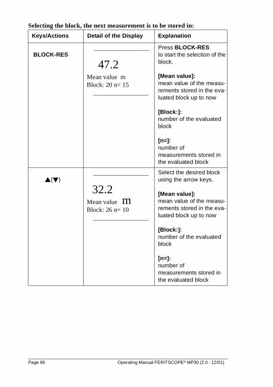
Selecting the block, the next measurement is to be stored in:
Keys/Actions Detail of the Display Explanation
BLOCK-RES _________________
47.2 Mean value m Block: 20 n= 15
_________________
Press BLOCK-RESto start the selection of the block.
[Mean value]: mean value of the measu-rements stored in the eva-luated block up to now
[Block:]: number of the evaluated block
[n=]: number of measurements stored in the evaluated block
�(�)_________________
32.2 Mean value m Block: 26 n= 10
_________________
Select the desired block using the arrow keys.
[Mean value]: mean value of the measu-rements stored in the eva-luated block up to now
[Block:]: number of the evaluated block
[n=]: number of measurements stored in the evaluated block
Page 86 Operating Manual FERITSCOPE® MP30 (2.0 - 12/01)
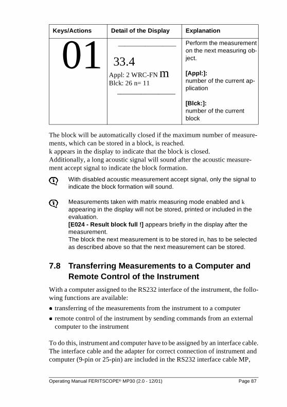
The block will be automatically closed if the maximum number of measure-ments, which can be stored in a block, is reached. k appears in the display to indicate that the block is closed. Additionally, a long acoustic signal will sound after the acoustic measure-ment accept signal to indicate the block formation.
With disabled acoustic measurement accept signal, only the signal to indicate the block formation will sound.
Measurements taken with matrix measuring mode enabled and k appearing in the display will not be stored, printed or included in the evaluation. [E024 - Result block full !] appears briefly in the display after the measurement.The block the next measurement is to be stored in, has to be selected as described above so that the next measurement can be stored.
7.8 Transferring Measurements to a Computer and Remote Control of the Instrument
With a computer assigned to the RS232 interface of the instrument, the follo-wing functions are available:
� transferring of the measurements from the instrument to a computer
� remote control of the instrument by sending commands from an external computer to the instrument
To do this, instrument and computer have to be assigned by an interface cable.The interface cable and the adapter for correct connection of instrument and computer (9-pin or 25-pin) are included in the RS232 interface cable MP,
01 _________________
33.4 Appl: 2 WRC-FN m Blck: 26 n= 11
_________________
Perform the measurement on the next measuring ob-ject.
[Appl:]: number of the current ap-plication
[Blck:]: number of the current block
Keys/Actions Detail of the Display Explanation
Operating Manual FERITSCOPE® MP30 (2.0 - 12/01) Page 87
which is available from Fischer or your local supplier.
Connecting a computer: see "10.5 Start-Up, Maintenance and Cle-aning", beginning on page 127”,
Factory settings and connector pin-out of the RS232 interface: see "14.2 Technical Data and Contents of Shipment", beginning on page 164.
Suitable commercial or self-programmed data processing software can be used to acquire and process the measurements coming from the instrument.
Refer to the corresponding software manuals for information about im-port and processing the measurements with this software.
7.8.1 Output Format of the Measurement Data String
The measurements will be transferred via the RS232 interface as floating point string followed by CR + LF.The word length, i. e. the number bits an ASCII character consists of, can be selected in the configuration program � ([Word length 7 Bits] or [Word length 8 Bits]).Selecting the word length: see "11.4.6 Instrument Configuration", beginning on page 143.
7.8.2 Transferring the Measurements to an External Computer
There are two modes to transfer the measurements from the instrument to an external computer:
� on-line mode and
� off-line mode.
In the on-line mode the instrument is assigned to the computer during measu-rement and the measurements are transferred to the computer immediately (on-line) after the measurement.
Single measurements are transferred via the RS232 interface imme-diately after measurement accept, if [Output to port Single meas.] is selected in the configuration program �. However, if [Output to port Block mean values] is selected, the block mean values will be transferred via the RS232 interface after pressing BLOCK-RES; the single measurements will be displayed but not transferred. Selecting the type of data to be transferred via the RS232 interface: see "11.4.6 Instrument Configuration", beginning on page 143.
Page 88 Operating Manual FERITSCOPE® MP30 (2.0 - 12/01)
In the off-line mode the measurements already stored in the instrument can be transferred via the RS232 interface at any time (off-line). The data transfer can be initiated by pressing PRINT.
Single measurements are transferred via the RS232 interface after pressing PRINT, if [Output to port Single meas.] is selected in the configuration program �. However, if [Output to port Block mean values] is selected, only the block mean values will be transferred. Selecting the type of data to be transferred via the RS232 interface: see "11.4.6 Instrument Configuration", beginning on page 143
A series of single measurements can be combined into a block by pressing BLOCK-RES (see "8.1 Evaluation", beginning on page 92). The end of each block formed by pressing BLOCK-RES can be marked with a group separator code (ASCII GS). The group separator will be written to the end of each block and transferred via the RS232 interface followed by CR + LF only if [Group separator On] has been selected in the configuration program �. Setting the group separator mode: see "11.4.6 Instrument Configuration", be-ginning on page 143
7.8.3 Remote Control of the Instrument
ASCII Decimal Hexadecimal
Function
G 0 71 48 47 30 Initiate a measurement accept and transfer the measurement via the RS232 interface.
ESC ? 27 63 1B 3F Initiate a measurement accept and transfer the measurement via the RS232 interface.
ESC0 27 48 1B 30 Actuate key DEL
ESC1 27 49 1B 31 Actuate key FINAL-RES
ESC2 27 50 1B 32 Actuate key BLOCK-RES
ESC3 27 51 1B 33 Actuate key ON/OFF
ESC4 27 52 1B 34 Actuate key ZERO
ESC5 27 53 1B 35 Actuate key CAL
ESC6 27 54 1B 36 Actuate key �
ESC7 27 55 1B 37 Actuate key �
Operating Manual FERITSCOPE® MP30 (2.0 - 12/01) Page 89
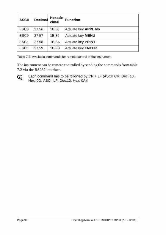
Table 7.2: Available commands for remote control of the instrument
The instrument can be remote controlled by sending the commands from table 7.2 via the RS232 interface.
Each command has to be followed by CR + LF (ASCII CR: Dec. 13, Hex. 0D; ASCII LF: Dec.10, Hex. 0A)!
ESC8 27 56 1B 38 Actuate key APPL No
ESC9 27 57 1B 39 Actuate key MENU
ESC: 27 58 1B 3A Actuate key PRINT
ESC; 27 59 1B 3B Actuate key ENTER
ASCII DecimalHexadecimal
Function
Page 90 Operating Manual FERITSCOPE® MP30 (2.0 - 12/01)
8 Evaluation
Two options for evaluation of the measured Ferrite Content are available:
� evaluation of the current block (block result)
� evaluation of the current application (final result)
When calling a block result or a final result, the following parameters are cal-culated from the measurements of the current block or the current application and can be displayed in succession:
� mean value
� number of the evaluated block or application
� number of the measurements evaluated
� standard deviation
� date and time of the block formation of the evaluated block or current date (if the evaluated block has not yet been closed)
� lowest or highest measurement or block mean value (if automatic block formation has been enabled)
� number of measurements violating the lower or the upper specification limit (only if specification limits monitoring is enabled)
When printing the result, the following will be printed in addition:
� current date
� 95% confidence interval for the mean value
� coefficient of variation C.O.V.
� Standard deviation sa (only when displaying or printing the final result if automatic block formation has been enabled)
� lower and upper specification limit LSL and USL
� process capability indices cp and cpk, estimated value s^ of the standard deviation (only if specification limits monitoring and automatic block for-mation have been enabled)
� histogram with information if a normal distribution of the measurements was found, skewness, kurtosis and a normal probability chart (only when printing the final result, and if the histogram mode [Histogram On] is selected in the configuration programs)
The block or final result cannot be called if there are no measurements stored in the current application or if the measurements have been de-leted!
Operating Manual FERITSCOPE® MP30 (2.0 - 12/01) Page 91
The display will not change after pressing BLOCK-RES or FINAL-RES.
With outlier rejection enabled, measurements recognized as outliers will not be included in the evaluation!
Detailed explanations about the evaluation parameters :see "16 Glossary of Terms and Symbols", beginning on page 177.
8.1 Evaluation of the Current Block (Block Result)
Single measurements are combined automatically into a block at evaluation of the current block. However, the block will not be closed until the evaluation is terminated by performing a measurement or pressing ENTER.If no measurements are stored in the current block, the block result of the last closed block will be displayed after pressing BLOCK-RES.
If k appears in the display, the evaluated block has been closed alrea-dy.
If the last block has not been closed when measuring with fixed block size, the next measurement will be added to this block (even if the evaluation was terminated with ENTER). The block formation is not accomplished until the number of measurements stored in this block equals the fixed block size (see "7.3.5 Measurement", beginning on page 72.
Page 92 Operating Manual FERITSCOPE® MP30 (2.0 - 12/01)
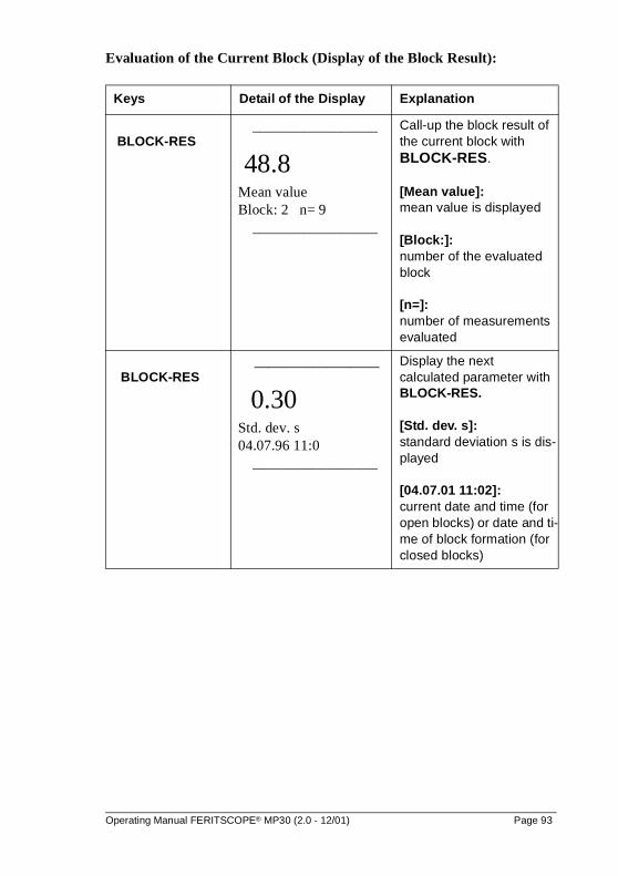
Evaluation of the Current Block (Display of the Block Result):
Keys Detail of the Display Explanation
BLOCK-RES_________________
48.8 Mean value Block: 2 n= 9
_________________
Call-up the block result of the current block with BLOCK-RES.
[Mean value]: mean value is displayed
[Block:]: number of the evaluated block
[n=]: number of measurements evaluated
BLOCK-RES _________________
0.30 Std. dev. s 04.07.96 11:0
_________________
Display the next calculated parameter with BLOCK-RES.
[Std. dev. s]: standard deviation s is dis-played
[04.07.01 11:02]: current date and time (for open blocks) or date and ti-me of block formation (for closed blocks)
Operating Manual FERITSCOPE® MP30 (2.0 - 12/01) Page 93
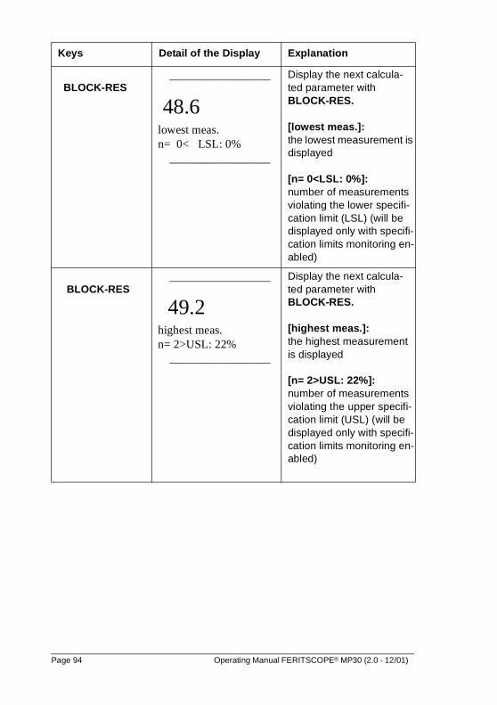
BLOCK-RES_________________
48.6 lowest meas. n= 0< LSL: 0%
_________________
Display the next calcula-ted parameter with BLOCK-RES.
[lowest meas.]: the lowest measurement is displayed
[n= 0<LSL: 0%]: number of measurements violating the lower specifi-cation limit (LSL) (will be displayed only with specifi-cation limits monitoring en-abled)
BLOCK-RES_________________
49.2 highest meas. n= 2>USL: 22%
_________________
Display the next calcula-ted parameter with BLOCK-RES.
[highest meas.]:the highest measurement is displayed
[n= 2>USL: 22%]: number of measurements violating the upper specifi-cation limit (USL) (will be displayed only with specifi-cation limits monitoring en-abled)
Keys Detail of the Display Explanation
Page 94 Operating Manual FERITSCOPE® MP30 (2.0 - 12/01)
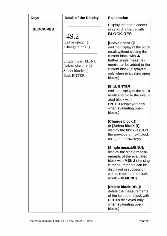
BLOCK-RES_________________
49.2 Leave open: { Change block: } _________________
Single meas: MENU Delete block: DEL Select block: {} End: ENTER
Display the notes concer-ning block closure with BLOCK-RES.
[Leave open: {]: end the display of the block result without closing the current block with �, further single measure-ments can be added to the current block (displayed only when evaluating open blocks)
[End: ENTER]: end the display of the block result and close the evalu-ated block with ENTER (displayed only when evaluating open blocks)
[Change block:}] or [Select block:{}]:display the block result of the previous or next block using the arrow keys
[Single meas:MENU]: display the single measu-rements of the evaluated block with MENU (the sing-le measurements can be displayed in succession with s, return to the block result with MENU)
[Delete block:DEL]: delete the measurements of the last open block with DEL (is displayed only when evaluating open blocks)
Keys Detail of the Display Explanation
Operating Manual FERITSCOPE® MP30 (2.0 - 12/01) Page 95
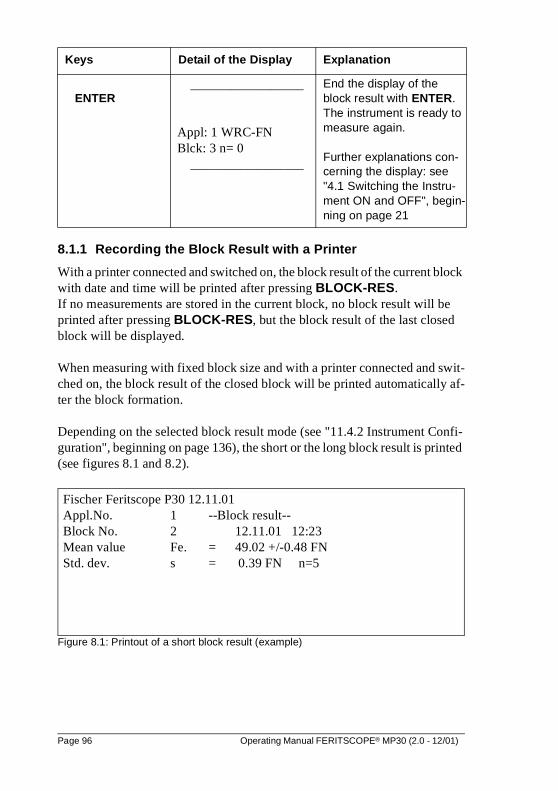
8.1.1 Recording the Block Result with a Printer
With a printer connected and switched on, the block result of the current block with date and time will be printed after pressing BLOCK-RES.If no measurements are stored in the current block, no block result will be printed after pressing BLOCK-RES, but the block result of the last closed block will be displayed.
When measuring with fixed block size and with a printer connected and swit-ched on, the block result of the closed block will be printed automatically af-ter the block formation.
Depending on the selected block result mode (see "11.4.2 Instrument Confi-guration", beginning on page 136), the short or the long block result is printed (see figures 8.1 and 8.2).
Figure 8.1: Printout of a short block result (example)
ENTER_________________
Appl: 1 WRC-FN Blck: 3 n= 0
_________________
End the display of the block result with ENTER. The instrument is ready to measure again.
Further explanations con-cerning the display: see "4.1 Switching the Instru-ment ON and OFF", begin-ning on page 21
Keys Detail of the Display Explanation
Fischer Feritscope P30 12.11.01Appl.No. 1 --Block result--Block No. 2 12.11.01 12:23Mean value Fe. = 49.02 +/-0.48 FNStd. dev. s = 0.39 FN n=5
Page 96 Operating Manual FERITSCOPE® MP30 (2.0 - 12/01)
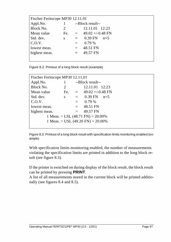
Figure 8.2: Printout of a long block result (example)
Figure 8.3: Printout of a long block result with specification limits monitoring enabled (ex-ample)
With specification limits monitoring enabled, the number of measurements violating the specification limits are printed in addition to the long block re-sult (see figure 8.3).
If the printer is switched on during display of the block result, the block result can be printed by pressing PRINT. A list of all measurements stored in the current block will be printed additio-nally (see figures 8.4 and 8.5).
Fischer Feritscope MP30 12.11.01Appl.No. 1 --Block result--Block No. 2 12.11.01 12:23Mean value Fe. = 49.02 +/-0.48 FNStd. dev. s = 0.39 FN n=5C.O.V. = 0.79 %lowest meas. = 48.51 FNhighest meas. = 49.57 FN
Fischer Feritscope MP30 12.11.01Appl.No. 1 --Block result--Block No. 2 12.11.01 12:23Mean value Fe. = 49.02 +/-0.48 FNStd. dev. s = 0.39 FN n=5C.O.V. = 0.79 %lowest meas. = 48.51 FNhighest meas. = 49.57 FN
1 Meas. < LSL (48.71 FN) = 20.00%1 Meas. > USL (49.20 FN) = 20.00%
Operating Manual FERITSCOPE® MP30 (2.0 - 12/01) Page 97
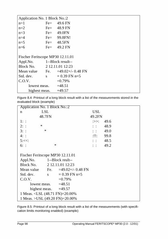
Figure 8.4: Printout of a long block result with a list of the measurements stored in the evaluated block (example)
Figure 8.5: Printout of a long block result with a list of the measurements (with specifi-cation limits monitoring enabled) (example)
Application No. 1 Block No.:2n=1 Fe= 49.6 FNn=2 Fe= 48.9 FNn=3 Fe= 49.0FNn=4 Fe= 99.8FN!n=5 Fe= 48.5FNn=6 Fe= 49.2 FN
Fischer Feritscope MP30 12.11.01Appl.No. 1--Block result--Block No. 2 12.11.01 12:23Mean value Fe. =49.02+/- 0.48 FNStd. dev. s = 0.39 FN n=5C.O.V. =0.79%
lowest meas. =48.51highest meas. =49.57
Application No. 1 Block No.:2n LSL USL
48.7FN 49.2FN1: : :>>: 49.62: : * : : 48.93: : * : : 49.04: : :!!: 99.85:<<: : : 48.56: : * : : 49.2
Fischer Feritscope MP30 12.11.01Appl.No. 1--Block reult--Block No. 2 12.11.01 12:23Mean value Fe. =49.02+/- 0.48 FNStd. dev. s = 0.39 FN n=5C.O.V. =0.79%
lowest meas. =48.51highest meas. =49.57
1 Meas. <LSL (48.71 FN)=20.00%1 Meas. >USL (49.20 FN)=20.00%
Page 98 Operating Manual FERITSCOPE® MP30 (2.0 - 12/01)
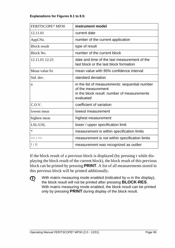
Explanations for Figures 8.1 to 8.5:
If the block result of a previous block is displayed (by pressing t while dis-playing the block result of the current block), the block result of this previous block can be printed by pressing PRINT. A list of all measurements stored in this previous block will be printed additionally.
With matrix measuring mode enabled (indicated by m in the display), the block result will not be printed after pressing BLOCK-RES. With matrix measuring mode enabled, the block result can be printed only by pressing PRINT during display of the block result.
FERITSCOPE® MP30 instrument model
12.11.01 current date
Appl.No. number of the current application
Block result type of result
Block No. number of the current block
12.11.01 12:23 date and time of the last measurement of thelast block or the last block formation
Mean value Fe mean value with 95% confidence interval
Std. dev. standard deviation
n in the list of measurements: sequential number of the measurementin the block result: number of measurements evaluated
C.O.V. coefficient of variation
lowest meas lowest measurement
highest meas highest measurement
LSL/USL lower / upper specification limit
* measurement is within specification limits
<< / >> measurement is not within specification limits
! / !! measurement was recognized as outlier
Operating Manual FERITSCOPE® MP30 (2.0 - 12/01) Page 99
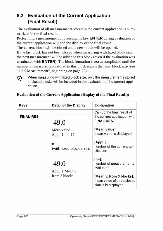
8.2 Evaluation of the Current Application (Final Result)
The evaluation of all measurements stored in the current application is sum-marized in the final result.Performing a measurement or pressing the key ENTER during evaluation of the current application will end the display of the final result. The current block will be closed and a new block will be opened.If the last block has not been closed when measuring with fixed block size, the next measurement will be added to this block (even if the evaluation was terminated with ENTER). The block formation is not accomplished until the number of measurements stored in this block equals the fixed block size (see "7.3.5 Measurement", beginning on page 72).
When measuring with fixed block size, only the measurements stored in closed blocks will be included in the evaluation of the current appli-cation.
Evaluation of the Current Application (Display of the Final Result):
Keys Detail of the Display Explanation
FINAL-RES_________________
49.0 Mean value Appl: 1 n= 17
_________________ or (with fixed block size):
_________________
49.0 Appl: 1 Mean v. from 3 blocks
_________________
Call-up the final result of the current application with FINAL-RES.
[Mean value]: mean value is displayed
[Appl:]: number of the current ap-plication
[n=]: number of measurements evaluated
[Mean v. from 3 blocks]: mean value of three closed blocks is displayed
Page 100 Operating Manual FERITSCOPE® MP30 (2.0 - 12/01)
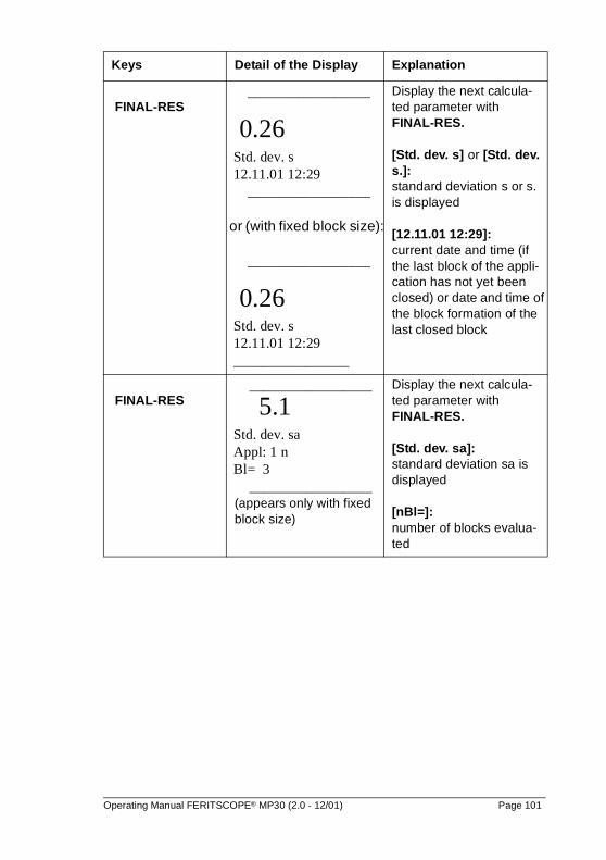
FINAL-RES_________________
0.26 Std. dev. s 12.11.01 12:29
_________________
or (with fixed block size):
_________________
0.26 Std. dev. s 12.11.01 12:29 ________________
Display the next calcula-ted parameter with FINAL-RES.
[Std. dev. s] or [Std. dev. s.]: standard deviation s or s. is displayed
[12.11.01 12:29]:current date and time (if the last block of the appli-cation has not yet been closed) or date and time of the block formation of the last closed block
FINAL-RES _________________
5.1 Std. dev. sa Appl: 1 n Bl= 3
_________________(appears only with fixed block size)
Display the next calcula-ted parameter withFINAL-RES.
[Std. dev. sa]: standard deviation sa is displayed
[nBl=]: number of blocks evalua-ted
Keys Detail of the Display Explanation
Operating Manual FERITSCOPE® MP30 (2.0 - 12/01) Page 101
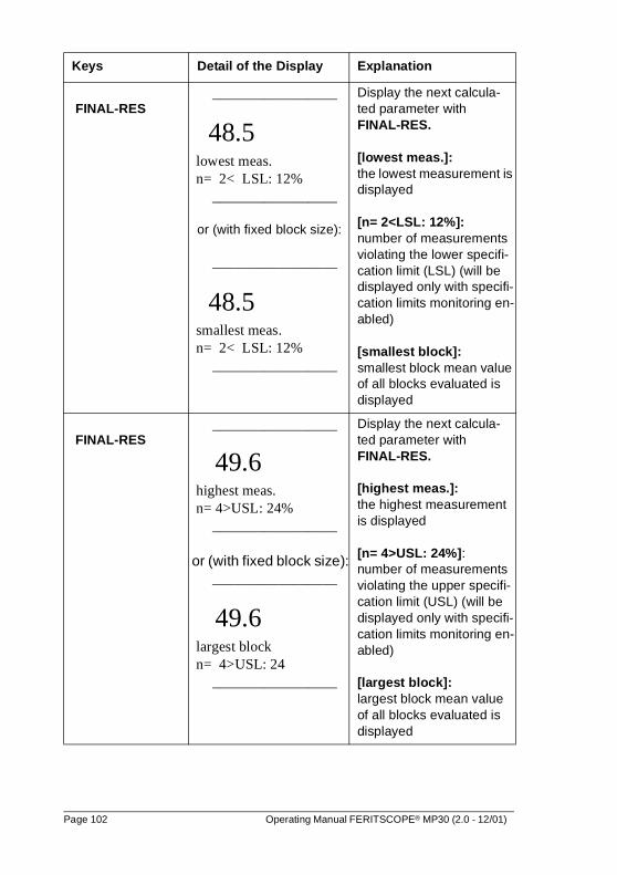
FINAL-RES _________________
48.5 lowest meas. n= 2< LSL: 12%
_________________
or (with fixed block size):
_________________
48.5 smallest meas. n= 2< LSL: 12%
_________________
Display the next calcula-ted parameter with FINAL-RES.
[lowest meas.]: the lowest measurement is displayed
[n= 2<LSL: 12%]: number of measurements violating the lower specifi-cation limit (LSL) (will be displayed only with specifi-cation limits monitoring en-abled)
[smallest block]: smallest block mean value of all blocks evaluated is displayed
FINAL-RES _________________
49.6 highest meas. n= 4>USL: 24%
_________________
or (with fixed block size): _________________
49.6 largest block n= 4>USL: 24
_________________
Display the next calcula-ted parameter with FINAL-RES.
[highest meas.]: the highest measurement is displayed
[n= 4>USL: 24%]: number of measurements violating the upper specifi-cation limit (USL) (will be displayed only with specifi-cation limits monitoring en-abled)
[largest block]: largest block mean value of all blocks evaluated is displayed
Keys Detail of the Display Explanation
Page 102 Operating Manual FERITSCOPE® MP30 (2.0 - 12/01)
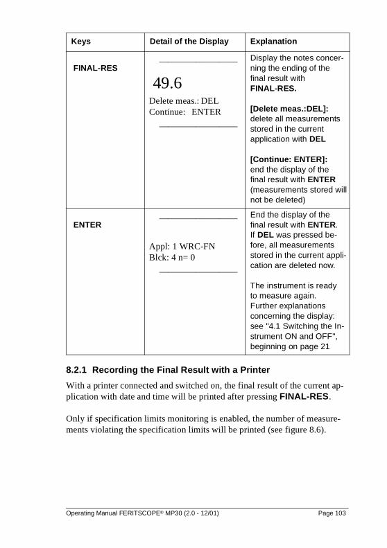
8.2.1 Recording the Final Result with a Printer
With a printer connected and switched on, the final result of the current ap-plication with date and time will be printed after pressing FINAL-RES.
Only if specification limits monitoring is enabled, the number of measure-ments violating the specification limits will be printed (see figure 8.6).
FINAL-RES _________________
49.6 Delete meas.: DEL Continue: ENTER
_________________
Display the notes concer-ning the ending of the final result with FINAL-RES.
[Delete meas.:DEL]: delete all measurements stored in the current application with DEL
[Continue: ENTER]: end the display of the final result with ENTER (measurements stored will not be deleted)
ENTER _________________
Appl: 1 WRC-FN Blck: 4 n= 0
_________________
End the display of thefinal result with ENTER. If DEL was pressed be-fore, all measurements stored in the current appli-cation are deleted now.
The instrument is ready to measure again. Further explanations concerning the display: see "4.1 Switching the In-strument ON and OFF", beginning on page 21
Keys Detail of the Display Explanation
Operating Manual FERITSCOPE® MP30 (2.0 - 12/01) Page 103
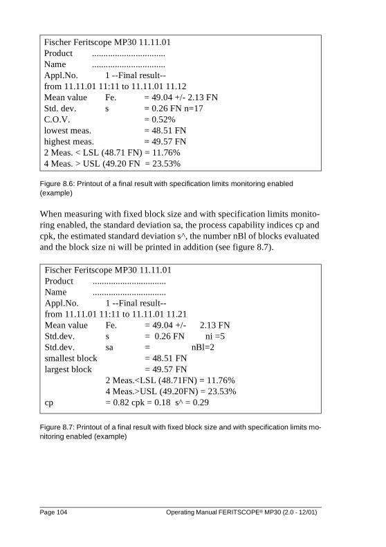
Figure 8.6: Printout of a final result with specification limits monitoring enabled (example)
When measuring with fixed block size and with specification limits monito-ring enabled, the standard deviation sa, the process capability indices cp and cpk, the estimated standard deviation s^, the number nBl of blocks evaluated and the block size ni will be printed in addition (see figure 8.7).
Figure 8.7: Printout of a final result with fixed block size and with specification limits mo-nitoring enabled (example)
Fischer Feritscope MP30 11.11.01Product ................................Name ................................Appl.No. 1 --Final result--from 11.11.01 11:11 to 11.11.01 11.12Mean value Fe. = 49.04 +/- 2.13 FNStd. dev. s = 0.26 FN n=17C.O.V. = 0.52%lowest meas. = 48.51 FNhighest meas. = 49.57 FN2 Meas. < LSL (48.71 FN) = 11.76%4 Meas. > USL (49.20 FN = 23.53%
Fischer Feritscope MP30 11.11.01Product ................................Name ................................Appl.No. 1 --Final result--from 11.11.01 11:11 to 11.11.01 11.21Mean value Fe. = 49.04 +/- 2.13 FNStd.dev. s = 0.26 FN ni =5Std.dev. sa = nBl=2smallest block = 48.51 FNlargest block = 49.57 FN
2 Meas.<LSL (48.71FN) = 11.76%4 Meas.>USL (49.20FN) = 23.53%
cp = 0.82 cpk = 0.18 s^ = 0.29
Page 104 Operating Manual FERITSCOPE® MP30 (2.0 - 12/01)
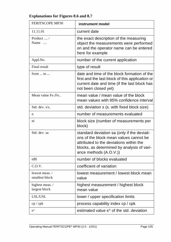
Explanations for Figures 8.6 and 8.7
FERITSCOPE MP30 instrument model
11.11.01 current date
Product .... / Name ....
the exact description of the measuring object the measurements were performed on and the operator name can be entered here for example
Appl.No. number of the current application
Final result type of result
from ... to ... date and time of the block formation of the first and the last block of this application or current date and time (if the last block has not been closed yet)
Mean value Fe./Fe.. mean value / mean value of the block mean values with 95% confidence interval
Std. dev. s/s. std. deviation s (s. with fixed block size)
n number of measurements evaluated
ni block size (number of measurements per block)
Std. dev. sa standard deviation sa (only if the deviati-ons of the block mean values cannot be attributed to the deviations within the blocks, as determined by analysis of vari-ance methods (A.O.V.))
nBl number of blocks evaluated
C.O.V. coefficient of variation
lowest meas. / smallest block
lowest measurement / lowest block mean value
highest meas. / largest block
highest measurement / highest block mean value
LSL/USL lower / upper specification limits
cp / cpk process capability index cp / cpk
s^ estimated value s^ of the std. deviation
Operating Manual FERITSCOPE® MP30 (2.0 - 12/01) Page 105
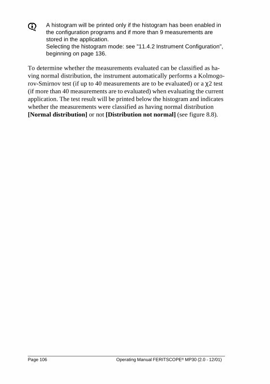
A histogram will be printed only if the histogram has been enabled in the configuration programs and if more than 9 measurements are stored in the application. Selecting the histogram mode: see "11.4.2 Instrument Configuration", beginning on page 136.
To determine whether the measurements evaluated can be classified as ha-ving normal distribution, the instrument automatically performs a Kolmogo-rov-Smirnov test (if up to 40 measurements are to be evaluated) or a χ2 test (if more than 40 measurements are to evaluated) when evaluating the current application. The test result will be printed below the histogram and indicates whether the measurements were classified as having normal distribution [Normal distribution] or not [Distribution not normal] (see figure 8.8).
Page 106 Operating Manual FERITSCOPE® MP30 (2.0 - 12/01)
Figure 8.8: Printout of a histogram
HISTOGRAMn48.4 :
1 :*48.6 :
1 :*48.8 :
6 :******49.0 :
5 :*****49.2 :
2 :**49.4 :
2 :**49.6 :
Distribution not normalSkewness = 0.04 Kurtosis=0.27
NORMAL PROBILITY CHART
Upper Limit Norm.Prob.Chart48.6 5.8848.8 11.76%49.0 47.06%49.2 76.47%49.4 88.24%49.6 100.00%
Operating Manual FERITSCOPE® MP30 (2.0 - 12/01) Page 107

Page 108 Operating Manual FERITSCOPE® MP30 (2.0 - 12/01)
9 Normalization and Corrective Calibration
The following factors affect the Ferrite Content measurement:
� geometry of the measuring object (size of the reference area, curvature and thickness of the measuring object, layer thickness and distance of the measuring position to the edge)
� wear of the probe tip
The effects of the geometry of the material to be measured can be corrected for by multiplication of the measured ferrite content and the corresponding correction factors.The wear of the probe tip can be corrected for up to a certain extent by cor-rective calibration. If the wear of the probe tip becomes too strong, no correc-tion is possible. The probe has to be sent to your local supplier or to Fischer for repair.
To ensure the measurement accuracy specified for the probe assi-gned, it is absolutely necessary to perform each normalization and cor-rective calibration very carefully.
It is absolutely necessary to follow the instructions see "2 Notes Concerning the Operation of the Instrument and Handling the Accessories", beginning on page 5.
Perform reference measurements after each normalization and correc-tive calibration to check the normalization or corrective calibration!
Following a normalization or corrective calibration the block will be clo-sed automatically and a new block will be opened. The measurements stored before performing the normalization or corrective calibration will not be deleted after the normalization or corrective calibration.If required, the measurements have to be deleted before the next mea-surement.
With the restricted operating mode enabled (indicated by e in the dis-play) it is not possible to start a normalization or corrective calibration!
With external start enabled, during normalization or corrective calibra-tion a measurement can be initiated by pressing FINAL-RES or by sending the command G0 (G Zero) via the RS232 interface.
Operating Manual FERITSCOPE® MP30 (2.0 - 12/01) Page 109
9.1 Reference Measurement
When performing a reference measurement, measurements are taken on a re-ference sample. If the deviations of these measurements from the ferrite con-tent of the reference sample violate the specified tolerances, the normalization or calibration has to be performed again.
A reference measurement requires:
� reference sample (coated measuring object with known ferrite content and of the same geometry as the objects to be measured)
Reference samples are subject to wear and tear caused by the tactile measurement. Reference samples have to be checked regularly and replaced by new reference samples if the wear and tear becomes significant.
9.2 Normalization
A normalization is necessary when creating a new application.During a normalization, a new zero point will be determined for the calibra-tion curve of the current application and stored.
A normalization requires:
� Base (supplied in the calibration standard set)
A normalization is valid only for the current application. The other ap-plications remain unchanged. However, if the linking mode is enabled (v in the display), the normali-zation is valid for all applications linked to the current application.
Page 110 Operating Manual FERITSCOPE® MP30 (2.0 - 12/01)
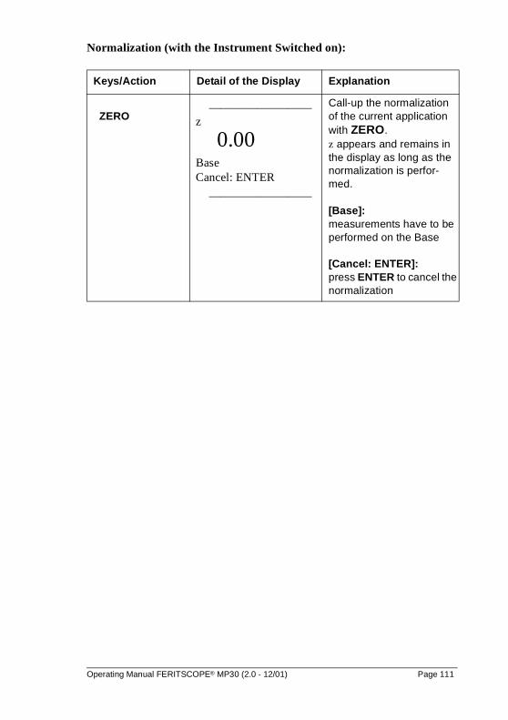
Normalization (with the Instrument Switched on):
Keys/Action Detail of the Display Explanation
ZERO _________________
z
0.00 Base Cancel: ENTER
_________________
Call-up the normalization of the current application with ZERO. z appears and remains in the display as long as the normalization is perfor-med.
[Base]: measurements have to be performed on the Base
[Cancel: ENTER]: press ENTER to cancel the normalization
Operating Manual FERITSCOPE® MP30 (2.0 - 12/01) Page 111
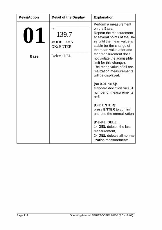
01 Base
_________________ z
139.7 s= 0.01 n= 5 OK: ENTER
_________________ Delete: DEL
Perform a measurement on the Base. Repeat the measurement at several points of the Ba-se until the mean value is stable (or the change of the mean value after ano-ther measurement does not violate the admissible limit for this change).The mean value of all nor-malization measurements will be displayed.
[s= 0.01 n= 5]: standard deviation s=0.01, number of measurements n=5
[OK: ENTER]: press ENTER to confirm and end the normalization
[Delete: DEL]: 1x DEL deletes the last measurement, 2x DEL deletes all norma-lization measurements
Keys/Action Detail of the Display Explanation
Page 112 Operating Manual FERITSCOPE® MP30 (2.0 - 12/01)
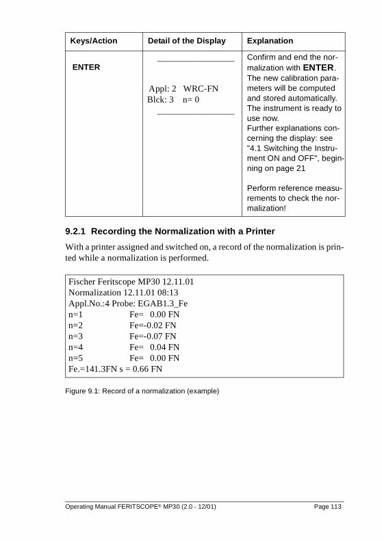
9.2.1 Recording the Normalization with a Printer
With a printer assigned and switched on, a record of the normalization is prin-ted while a normalization is performed.
Figure 9.1: Record of a normalization (example)
ENTER _________________
Appl: 2 WRC-FN Blck: 3 n= 0
_________________
Confirm and end the nor-malization with ENTER. The new calibration para-meters will be computed and stored automatically. The instrument is ready to use now.Further explanations con-cerning the display: see "4.1 Switching the Instru-ment ON and OFF", begin-ning on page 21
Perform reference measu-rements to check the nor-malization!
Keys/Action Detail of the Display Explanation
Fischer Feritscope MP30 12.11.01Normalization 12.11.01 08:13Appl.No.:4 Probe: EGAB1.3_Fen=1 Fe= 0.00 FNn=2 Fe=-0.02 FNn=3 Fe=-0.07 FNn=4 Fe= 0.04 FNn=5 Fe= 0.00 FNFe.=141.3FN s = 0.66 FN
Operating Manual FERITSCOPE® MP30 (2.0 - 12/01) Page 113
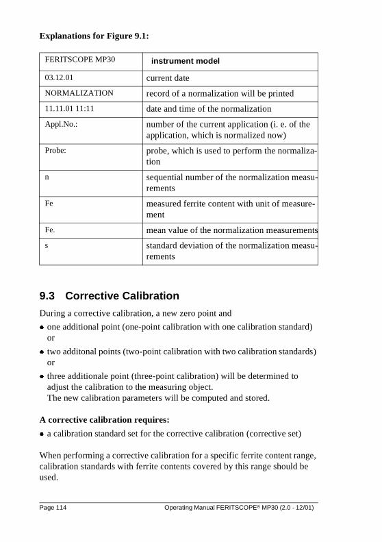
Explanations for Figure 9.1:
9.3 Corrective Calibration
During a corrective calibration, a new zero point and
� one additional point (one-point calibration with one calibration standard) or
� two additonal points (two-point calibration with two calibration standards) or
� three additionale point (three-point calibration) will be determined to adjust the calibration to the measuring object. The new calibration parameters will be computed and stored.
A corrective calibration requires:
� a calibration standard set for the corrective calibration (corrective set)
When performing a corrective calibration for a specific ferrite content range, calibration standards with ferrite contents covered by this range should be used.
FERITSCOPE MP30 instrument model
03.12.01 current date
NORMALIZATION record of a normalization will be printed
11.11.01 11:11 date and time of the normalization
Appl.No.: number of the current application (i. e. of the application, which is normalized now)
Probe: probe, which is used to perform the normaliza-tion
n sequential number of the normalization measu-rements
Fe measured ferrite content with unit of measure-ment
Fe. mean value of the normalization measurements
s standard deviation of the normalization measu-rements
Page 114 Operating Manual FERITSCOPE® MP30 (2.0 - 12/01)
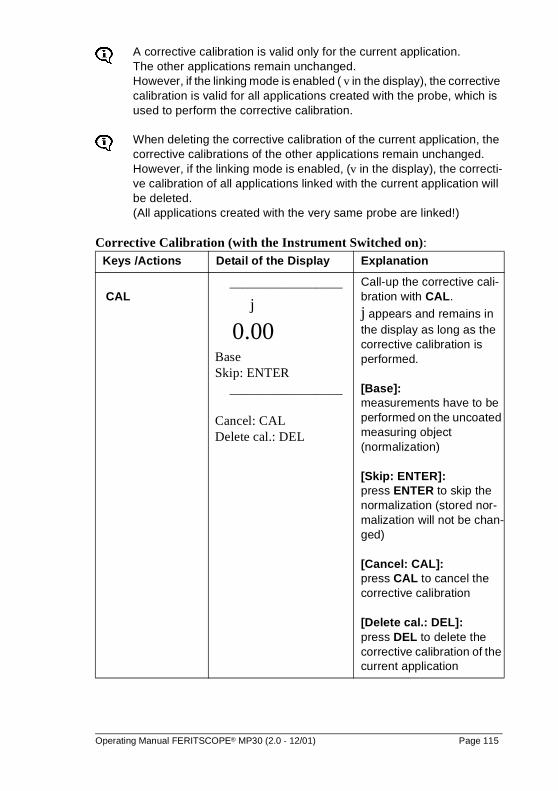
A corrective calibration is valid only for the current application. The other applications remain unchanged.However, if the linking mode is enabled ( v in the display), the corrective calibration is valid for all applications created with the probe, which is used to perform the corrective calibration.
When deleting the corrective calibration of the current application, the corrective calibrations of the other applications remain unchanged. However, if the linking mode is enabled, (v in the display), the correcti-ve calibration of all applications linked with the current application will be deleted.(All applications created with the very same probe are linked!)
Corrective Calibration (with the Instrument Switched on):Keys /Actions Detail of the Display Explanation
CAL _________________
j 0.00 Base Skip: ENTER
_________________ Cancel: CAL Delete cal.: DEL
Call-up the corrective cali-bration with CAL.
j appears and remains in the display as long as the corrective calibration is performed.
[Base]: measurements have to be performed on the uncoated measuring object (normalization)
[Skip: ENTER]: press ENTER to skip the normalization (stored nor-malization will not be chan-ged)
[Cancel: CAL]: press CAL to cancel the corrective calibration
[Delete cal.: DEL]: press DEL to delete the corrective calibration of the current application
Operating Manual FERITSCOPE® MP30 (2.0 - 12/01) Page 115
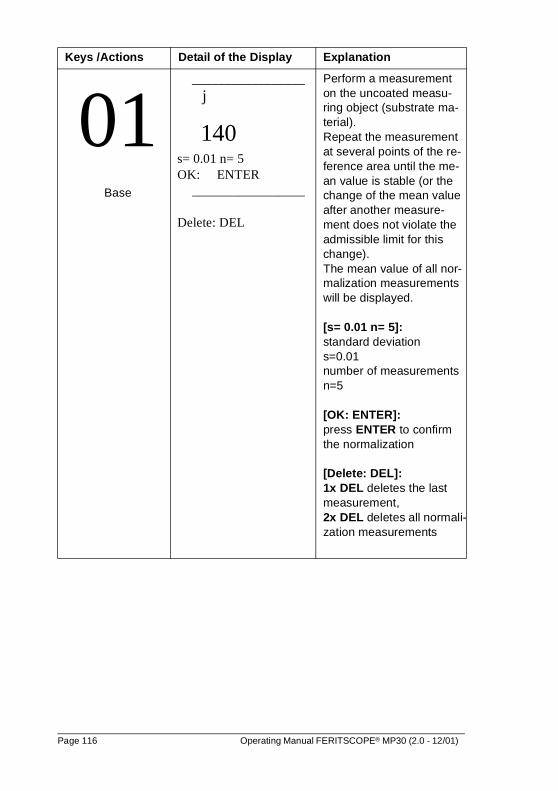
01Base
_________________ j
140 s= 0.01 n= 5 OK: ENTER
_________________
Delete: DEL
Perform a measurement on the uncoated measu-ring object (substrate ma-terial). Repeat the measurement at several points of the re-ference area until the me-an value is stable (or the change of the mean value after another measure-ment does not violate the admissible limit for this change). The mean value of all nor-malization measurements will be displayed.
[s= 0.01 n= 5]: standard deviation s=0.01 number of measurements n=5
[OK: ENTER]: press ENTER to confirm the normalization
[Delete: DEL]: 1x DEL deletes the last measurement, 2x DEL deletes all normali-zation measurements
Keys /Actions Detail of the Display Explanation
Page 116 Operating Manual FERITSCOPE® MP30 (2.0 - 12/01)
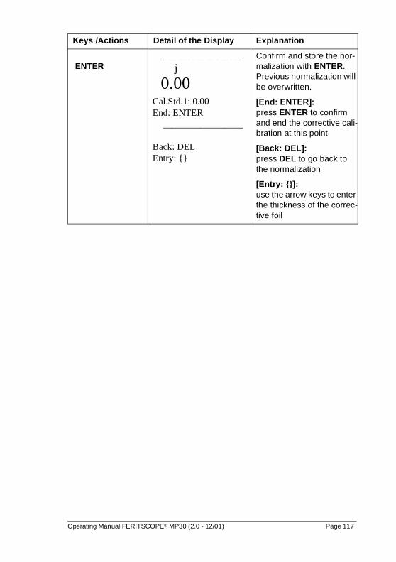
ENTER _________________
j
0.00 Cal.Std.1: 0.00 End: ENTER
_________________
Back: DEL Entry: {}
Confirm and store the nor-malization with ENTER. Previous normalization will be overwritten.
[End: ENTER]: press ENTER to confirm and end the corrective cali-bration at this point
[Back: DEL]: press DEL to go back to the normalization
[Entry: {}]: use the arrow keys to enter the thickness of the correc-tive foil
Keys /Actions Detail of the Display Explanation
Operating Manual FERITSCOPE® MP30 (2.0 - 12/01) Page 117
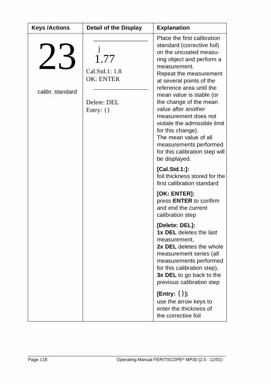
23calibr. standard
_________________
j
1.77 Cal.Std.1: 1.8 OK: ENTER
_________________
Delete: DEL Entry: {}
Place the first calibration standard (corrective foil) on the uncoated measu-ring object and perform a measurement.Repeat the measurement at several points of the reference area until the mean value is stable (or the change of the mean value after another measurement does not violate the admissible limit for this change). The mean value of all measurements performed for this calibration step will be displayed.
[Cal.Std.1:]: foil thickness stored for the first calibration standard
[OK: ENTER]: press ENTER to confirm and end the current calibration step
[Delete: DEL]: 1x DEL deletes the last measurement, 2x DEL deletes the whole measurement series (all measurements performed for this calibration step), 3x DEL to go back to the previous calibration step
[Entry: {}]: use the arrow keys to enter the thickness of the corrective foil
Keys /Actions Detail of the Display Explanation
Page 118 Operating Manual FERITSCOPE® MP30 (2.0 - 12/01)
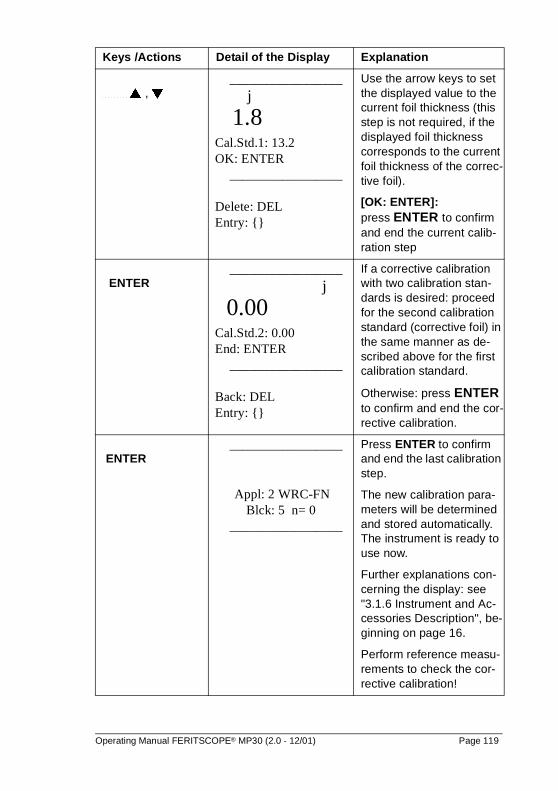
� , � _________________
j
1.8 Cal.Std.1: 13.2 OK: ENTER
_________________
Delete: DEL Entry: {}
Use the arrow keys to set the displayed value to the current foil thickness (this step is not required, if the displayed foil thickness corresponds to the current foil thickness of the correc-tive foil).
[OK: ENTER]: press ENTER to confirm and end the current calib-ration step
ENTER _________________
j
0.00 Cal.Std.2: 0.00 End: ENTER
_________________
Back: DEL Entry: {}
If a corrective calibration with two calibration stan-dards is desired: proceed for the second calibration standard (corrective foil) in the same manner as de-scribed above for the first calibration standard.
Otherwise: press ENTER to confirm and end the cor-rective calibration.
ENTER _________________
Appl: 2 WRC-FN
Blck: 5 n= 0 _________________
Press ENTER to confirm and end the last calibration step.
The new calibration para-meters will be determined and stored automatically. The instrument is ready to use now.
Further explanations con-cerning the display: see "3.1.6 Instrument and Ac-cessories Description", be-ginning on page 16.
Perform reference measu-rements to check the cor-rective calibration!
Keys /Actions Detail of the Display Explanation
Operating Manual FERITSCOPE® MP30 (2.0 - 12/01) Page 119
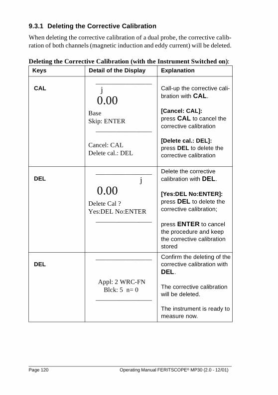
9.3.1 Deleting the Corrective Calibration
When deleting the corrective calibration of a dual probe, the corrective calib-ration of both channels (magnetic induction and eddy current) will be deleted.
Deleting the Corrective Calibration (with the Instrument Switched on):Keys Detail of the Display Explanation
CAL _________________
j
0.00 Base Skip: ENTER
_________________ Cancel: CAL Delete cal.: DEL
Call-up the corrective cali-bration with CAL.
[Cancel: CAL]: press CAL to cancel the corrective calibration
[Delete cal.: DEL]:press DEL to delete the corrective calibration
DEL _________________
j
0.00 Delete Cal ? Yes:DEL No:ENTER
_________________
Delete the corrective calibration with DEL.
[Yes:DEL No:ENTER]: press DEL to delete the corrective calibration;
press ENTER to cancel the procedure and keep the corrective calibration stored
DEL _________________
Appl: 2 WRC-FN
Blck: 5 n= 0 _________________
Confirm the deleting of the corrective calibration with DEL.
The corrective calibration will be deleted.
The instrument is ready to measure now.
Page 120 Operating Manual FERITSCOPE® MP30 (2.0 - 12/01)
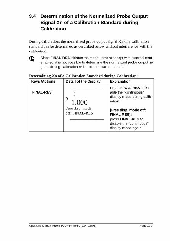
9.4 Determination of the Normalized Probe Output Signal Xn of a Calibration Standard during Calibration
During calibration, the normalized probe output signal Xn of a calibration standard can be determined as described below without interference with the calibration.
Since FINAL-RES initiates the measurement accept with external start enabled, it is not possible to determine the normalized probe output si-gnals during calibration with external start enabled!
Determining Xn of a Calibration Standard during Calibration:Keys /Actions Detail of the Display Explanation
FINAL-RES _________________
j p 1.000 Free disp. mode off: FINAL-RES
_________________
Press FINAL-RES to en-able the “continuous” display mode during calib-ration.
[Free disp. mode off: FINAL-RES]: press FINAL-RES to disable the “continuous” display mode again
Operating Manual FERITSCOPE® MP30 (2.0 - 12/01) Page 121
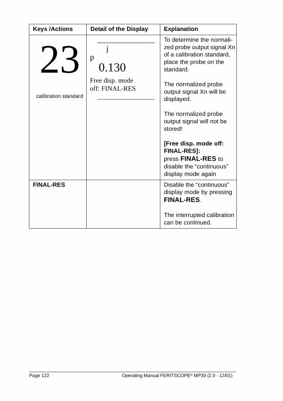
23calibration standard
_________________ j
p
0.130 Free disp. mode off: FINAL-RES
_________________
To determine the normali-zed probe output signal Xn of a calibration standard, place the probe on the standard.
The normalized probe output signal Xn will be displayed.
The normalized probe output signal will not be stored!
[Free disp. mode off: FINAL-RES]: press FINAL-RES to disable the “continuous” display mode again
FINAL-RES Disable the “continuous” display mode by pressing FINAL-RES.
The interrupted calibration can be continued.
Keys /Actions Detail of the Display Explanation
Page 122 Operating Manual FERITSCOPE® MP30 (2.0 - 12/01)

10 Start-Up, Maintenance and Cleaning
Switch the instrument off before connecting or disconnecting any components! Switch the instrument off before connecting the AC power supply or changing the battery! Even small electrical di-scharges may delete internally stored data.
To prevent damage to the connector pins do not tilt the plug when inserting or disconnecting it.
It is absolutely necessary to follow this instructions -> see "2 Notes Concerning the Operation of the Instrument and Handling the Accessories", beginning on page 5
10.1 Instrument Start-Up
An instrument start-up includes the following steps:
� providing a power supply for the instrumentsee "10.2 Start-Up, Maintenance and Cleaning", beginning on page 123
� connecting a probe to the instrument see "10.3 Start-Up, Maintenance and Cleaning", beginning on page 125
� connecting a printer (if available) to the instrumentsee "10.4 Start-Up, Maintenance and Cleaning", beginning on page 127
� connecting an external computer (if desired) to the instrumentsee "10.5 Start-Up, Maintenance and Cleaning", beginning on page 127
10.2 Power Supply
There are three ways to provide power for the instrument:
� AC power supply
� 9 V battery
� rechargeable 9 V NiCd battery
To prevent damage to the instrument or wrong measurement results due to wrong A/C line voltage, connect the instrument toa power outlet only with the AC power supply supplied by Fischer.The A/C line voltage must agree with the A/C line voltage rating on the serial number plate of the AC power supply.
Operating Manual FERITSCOPE® MP30 (2.0 - 12/01) Page 123
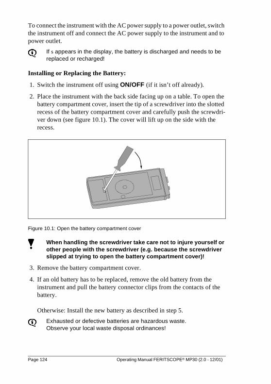
To connect the instrument with the AC power supply to a power outlet, switch the instrument off and connect the AC power supply to the instrument and to power outlet.
If s appears in the display, the battery is discharged and needs to be replaced or recharged!
Installing or Replacing the Battery:
1. Switch the instrument off using ON/OFF (if it isn’t off already).
2. Place the instrument with the back side facing up on a table. To open the battery compartment cover, insert the tip of a screwdriver into the slotted recess of the battery compartment cover and carefully push the screwdri-ver down (see figure 10.1). The cover will lift up on the side with the recess.
Figure 10.1: Open the battery compartment cover
When handling the screwdriver take care not to injure yourself or other people with the screwdriver (e.g. because the screwdriver slipped at trying to open the battery compartment cover)!
3. Remove the battery compartment cover.
4. If an old battery has to be replaced, remove the old battery from the instrument and pull the battery connector clips from the contacts of the battery.
Otherwise: Install the new battery as described in step 5.
Exhausted or defective batteries are hazardous waste. Observe your local waste disposal ordinances!
Page 124 Operating Manual FERITSCOPE® MP30 (2.0 - 12/01)
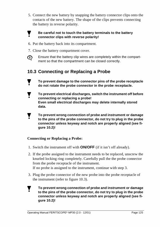
5. Connect the new battery by snapping the battery connector clips onto the contacts of the new battery. The shape of the clips prevents connecting the battery in reverse polarity.
Be careful not to touch the battery terminals to the battery connector clips with reverse polarity!
6. Put the battery back into its compartment.
7. Close the battery compartment cover.
Ensure that the battery clip wires are completely within the compart-ment so that the compartment can be closed correctly.
10.3 Connecting or Replacing a Probe
To prevent damage to the connector pins of the probe receptacle do not rotate the probe connector in the probe receptacle.
To prevent electrical discharges, switch the instrument off before connecting or replacing a probe! Even small electrical discharges may delete internally stored data.
To prevent wrong connection of probe and instrument or damage to the pins of the probe connector, do not try to plug in the probe connector unless keyway and notch are properly aligned (see fi-gure 10.2)!
Connecting or Replacing a Probe:
1. Switch the instrument off with ON/OFF (if it isn’t off already).
2. If the probe assigned to the instrument needs to be replaced, unscrew the knurled locking ring completely. Carefully pull the the probe connector from the probe receptacle of the instrument.If no probe is assigned to the instrument, continue with step 3.
3. Plug the probe connector of the new probe into the probe receptacle of the instrument (refer to figure 10.3).
To prevent wrong connection of probe and instrument or damage to the pins of the probe connector, do not try to plug in the probe connector unless keyway and notch are properly aligned (see fi-gure 10.2)!
Operating Manual FERITSCOPE® MP30 (2.0 - 12/01) Page 125
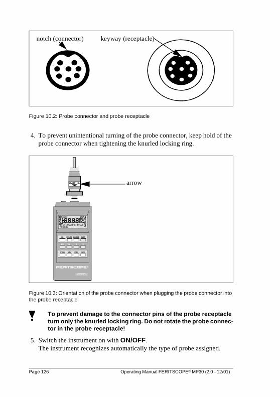
Figure 10.2: Probe connector and probe receptacle
4. To prevent unintentional turning of the probe connector, keep hold of the probe connector when tightening the knurled locking ring.
Figure 10.3: Orientation of the probe connector when plugging the probe connector into the probe receptacle
To prevent damage to the connector pins of the probe receptacle turn only the knurled locking ring. Do not rotate the probe connec-tor in the probe receptacle!
5. Switch the instrument on with ON/OFF. The instrument recognizes automatically the type of probe assigned.
notch (connector) keyway (receptacle)
arrow
Page 126 Operating Manual FERITSCOPE® MP30 (2.0 - 12/01)
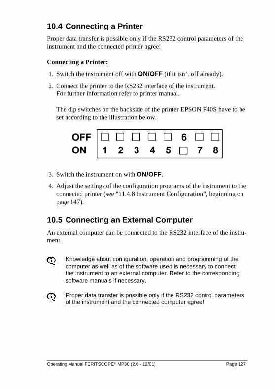
10.4 Connecting a Printer
Proper data transfer is possible only if the RS232 control parameters of the instrument and the connected printer agree!
Connecting a Printer:
1. Switch the instrument off with ON/OFF (if it isn’t off already).
2. Connect the printer to the RS232 interface of the instrument. For further information refer to printer manual.
The dip switches on the backside of the printer EPSON P40S have to be set according to the illustration below.
3. Switch the instrument on with ON/OFF.
4. Adjust the settings of the configuration programs of the instrument to the connected printer (see "11.4.8 Instrument Configuration", beginning on page 147).
10.5 Connecting an External Computer
An external computer can be connected to the RS232 interface of the instru-ment.
Knowledge about configuration, operation and programming of the computer as well as of the software used is necessary to connect the instrument to an external computer. Refer to the corresponding software manuals if necessary.
Proper data transfer is possible only if the RS232 control parameters of the instrument and the connected computer agree!
Operating Manual FERITSCOPE® MP30 (2.0 - 12/01) Page 127
Connecting an External Computer:
1. Switch the instrument off with ON/OFF (if it isn’t off already).
2. Connect the computer to the RS232 interface (with RS232 interface cable MP).
3. Set the control parameters of the RS232 interface of the instrument see "11.4.6 Instrument Configuration", beginning on page 143.
Factory settings and connector pin-out of the RS232 interface of the instrument: see "11.4.2 Instrument Configuration", beginning on page 136
10.6 Cleaning
To prevent the instrument or the accessories from damage caused by electrical strokes, the instrument or the accessories must be unplugged before performing any cleaning work!
Should the instrument or the accessories get dirty, clean them with a cleaner suited for plastics and a soft cloth.
When cleaning observe the following:
Wipe off dirt immediately before it gets a chance to adhere to the sur-face!
Do not use aggressive cleaners that may blemish the plastic hou-sing!
To prevent the instrument or the accessories from damage, do not clean them by scraping off the dirt, especially not near the probe tips.
Prevent water or any other liquid from entering the instrument or the accessories! (Danger of short circuits!) Do not immerse the instrument or the accessories into liquids to remove dirt by soaking!Do not pour any liquids over the instrument!
Page 128 Operating Manual FERITSCOPE® MP30 (2.0 - 12/01)
11 Instrument Configuration
Certain instrument settings, i.e. time and date, the unit of measurement or the control parameters of the RS232 interface, can be changed as required.
11.1 Acoustic Measurement Accept Signal
The acoustic measurement accept signal, i.e. the acoustic signal that sounds after each measurement, can be disabled.
The acoustic signals that sound after switching the instrument on, after violation of the specification limits, after recognition of an outlier mea-surement or after automatic block formation (when measuring with fi-xed block size), cannot be disabled!Details about the acoustic signals: see "7.3.3 Measurement", begin-ning on page 70.
11.1.1 Enabling the Measurement Accept Signal
To enable the acoustic measurement accept signal after the instrument has been switched off, switch the instrument on using the key ON/OFF immedi-ately followed by the key �.
The acoustic measurement accept signal remains enabled unless it will be disabled again. It is not necessary to enable the acoustic measurement accept signal each time, the instrument is switched on.
11.1.2 Disabling the Measurement Accept Signal
Pressing the key � immediately after switching the instrument on using ON/OFF will disable the acoustic measurement accept signal, i.e. the measu-rement accept signal will no longer sound from then on.
The acoustic measurement accept signal remains disabled unless it will be en-abled again. It is not necessary to disable the acoustic measurement accept si-gnal each time, the instrument is switched on.
Operating Manual FERITSCOPE® MP30 (2.0 - 12/01) Page 129
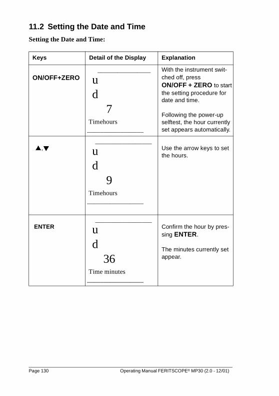
11.2 Setting the Date and Time
Setting the Date and Time:
Keys Detail of the Display Explanation
ON/OFF+ZERO ________________
u d
7 Timehours _________________
With the instrument swit-ched off, press ON/OFF + ZERO to start the setting procedure for date and time.
Following the power-up selftest, the hour currently set appears automatically.
�,�_________________
u d
9 Timehours _________________
Use the arrow keys to set the hours.
ENTER_________________
u d
36 Time minutes _________________
Confirm the hour by pres-sing ENTER.
The minutes currently set appear.
Page 130 Operating Manual FERITSCOPE® MP30 (2.0 - 12/01)
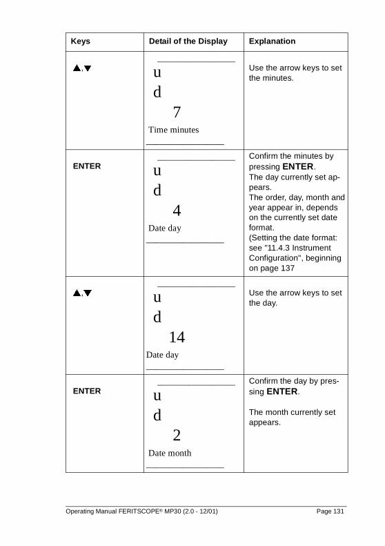
�,�_________________
u d
7 Time minutes _________________
Use the arrow keys to set the minutes.
ENTER_________________
u d
4 Date day _________________
Confirm the minutes by pressing ENTER. The day currently set ap-pears.The order, day, month and year appear in, depends on the currently set date format. (Setting the date format: see "11.4.3 Instrument Configuration", beginning on page 137
�,�_________________
u d
14 Date day _________________
Use the arrow keys to set the day.
ENTER_________________
u d
2 Date month _________________
Confirm the day by pres-sing ENTER.
The month currently set appears.
Keys Detail of the Display Explanation
Operating Manual FERITSCOPE® MP30 (2.0 - 12/01) Page 131
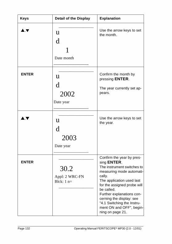
�,�_________________
u d
1 Date month _________________
Use the arrow keys to set the month.
ENTER_________________
u d
2002 Date year _________________
Confirm the month by pressing ENTER.
The year currently set ap-pears.
�,�_________________
u d
2003 Date year _________________
Use the arrow keys to set the year.
ENTER_________________
30.2 Appl: 2 WRC-FN Blck: 1 n=
_________________
Confirm the year by pres-sing ENTER. The instrument switches to measuring mode automati-cally. The application used last for the assigned probe will be called. Further explanations con-cerning the display: see "4.1 Switching the Instru-ment ON and OFF", begin-ning on page 21.
Keys Detail of the Display Explanation
Page 132 Operating Manual FERITSCOPE® MP30 (2.0 - 12/01)
Another way to set the date and time is described in the configuration programs (see "11.4.3 Instrument Configuration", beginning on page 137).
11.3 Restricted Operating Mode
With the restricted operating mode enabled, only those keys necessary for measurement and evaluation are active. This may prevent erroneous measu-rements due to unintentional changes to the instrument parameters.
With the restricted operating mode enabled, the following keys are deactiva-ted:
� ZERO
� CAL
� MENUPressing these keys will not trigger any action, the display will not change. In addition, it is not possible to call-up the configuration programs, to create, overwrite or delete applications!
11.3.1 Enabling and Disabling the Restricted Operating Mode
To enable the restricted operating mode with the instrument switched off, switch the instrument on using the key ON/OFF immediately followed by the key DEL.
As long as the restricted operating mode is enabled, e appears in the display.
The restricted operating mode remains enabled unless it will be disabled. It is not necessary to enable the restricted operating mode each time, the in-strument is switched on.
Pressing the key ENTER immediately after switching the instrument on using the key ON/OFF will disable the restricted operating mode again.
Operating Manual FERITSCOPE® MP30 (2.0 - 12/01) Page 133
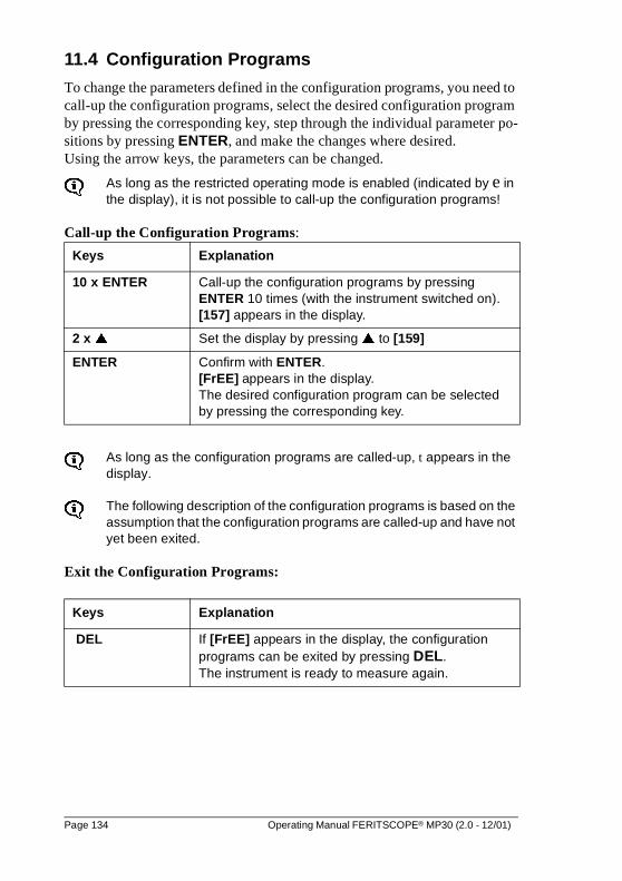
11.4 Configuration Programs
To change the parameters defined in the configuration programs, you need to call-up the configuration programs, select the desired configuration program by pressing the corresponding key, step through the individual parameter po-sitions by pressing ENTER, and make the changes where desired. Using the arrow keys, the parameters can be changed.
As long as the restricted operating mode is enabled (indicated by e in the display), it is not possible to call-up the configuration programs!
Call-up the Configuration Programs:
As long as the configuration programs are called-up, t appears in the display.
The following description of the configuration programs is based on the assumption that the configuration programs are called-up and have not yet been exited.
Exit the Configuration Programs:
Keys Explanation
10 x ENTER Call-up the configuration programs by pressing ENTER 10 times (with the instrument switched on). [157] appears in the display.
2 x � Set the display by pressing � to [159]
ENTER Confirm with ENTER. [FrEE] appears in the display. The desired configuration program can be selected by pressing the corresponding key.
Keys Explanation
DEL If [FrEE] appears in the display, the configuration programs can be exited by pressing DEL. The instrument is ready to measure again.
Page 134 Operating Manual FERITSCOPE® MP30 (2.0 - 12/01)
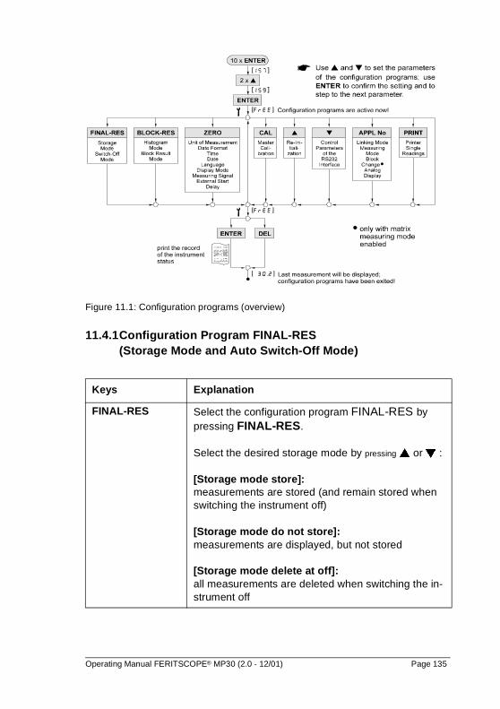
Figure 11.1: Configuration programs (overview)
11.4.1Configuration Program FINAL-RES (Storage Mode and Auto Switch-Off Mode)
Keys Explanation
FINAL-RES Select the configuration program FINAL-RES by pressing FINAL-RES.
Select the desired storage mode by pressing � or � :
[Storage mode store]: measurements are stored (and remain stored when switching the instrument off)
[Storage mode do not store]:measurements are displayed, but not stored
[Storage mode delete at off]: all measurements are deleted when switching the in-strument off
Operating Manual FERITSCOPE® MP30 (2.0 - 12/01) Page 135
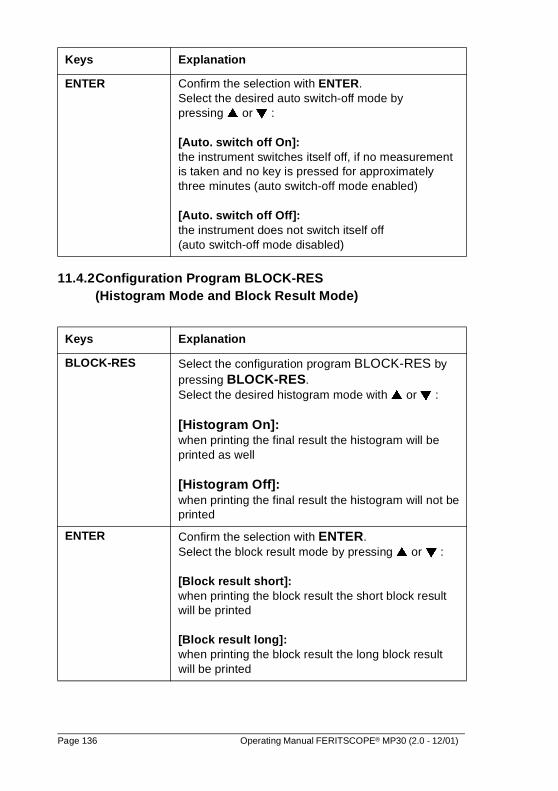
11.4.2Configuration Program BLOCK-RES (Histogram Mode and Block Result Mode)
ENTER Confirm the selection with ENTER. Select the desired auto switch-off mode by pressing � or � :
[Auto. switch off On]: the instrument switches itself off, if no measurementis taken and no key is pressed for approximatelythree minutes (auto switch-off mode enabled)
[Auto. switch off Off]: the instrument does not switch itself off (auto switch-off mode disabled)
Keys Explanation
BLOCK-RES Select the configuration program BLOCK-RES by pressing BLOCK-RES. Select the desired histogram mode with � or � :
[Histogram On]: when printing the final result the histogram will be printed as well
[Histogram Off]: when printing the final result the histogram will not be printed
ENTER Confirm the selection with ENTER. Select the block result mode by pressing � or � :
[Block result short]: when printing the block result the short block result will be printed
[Block result long]: when printing the block result the long block result will be printed
Keys Explanation
Page 136 Operating Manual FERITSCOPE® MP30 (2.0 - 12/01)
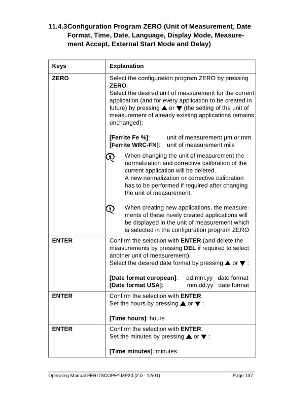
11.4.3Configuration Program ZERO (Unit of Measurement, Date Format, Time, Date, Language, Display Mode, Measure-ment Accept, External Start Mode and Delay)
Keys Explanation
ZERO Select the configuration program ZERO by pressing ZERO. Select the desired unit of measurement for the current application (and for every application to be created in future) by pressing � or � (the setting of the unit of measurement of already existing applications remains unchanged):
[Ferrite Fe %]: unit of measurement µm or mm[Ferrite WRC-FN]: unit of measurement mils
When changing the unit of measurement the normalization and corrective calibration of the current application will be deleted. A new normalization or corrective calibration has to be performed if required after changingthe unit of measurement.
When creating new applications, the measure-ments of these newly created applications will be displayed in the unit of measurement whichis selected in the configuration program ZERO
ENTER Confirm the selection with ENTER (and delete the measurements by pressing DEL if required to select another unit of measurement).Select the desired date format by pressing � or � :
[Date format european]: dd.mm.yy date format [Date format USA]: mm.dd.yy date format
ENTER Confirm the selection with ENTER. Set the hours by pressing � or � :
[Time hours]: hours
ENTER Confirm the selection with ENTER.Set the minutes by pressing � or � :
[Time minutes]: minutes
Operating Manual FERITSCOPE® MP30 (2.0 - 12/01) Page 137
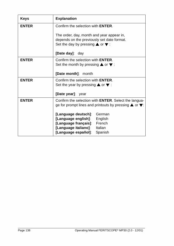
ENTER Confirm the selection with ENTER.
The order, day, month and year appear in, depends on the previously set date format.Set the day by pressing � or � :
[Date day]: day
ENTER Confirm the selection with ENTER.Set the month by pressing � or � :
[Date month]: month
ENTER Confirm the selection with ENTER. Set the year by pressing � or � :
[Date year]: year
ENTER Confirm the selection with ENTER. Select the langua-ge for prompt lines and printouts by pressing � or �:
[Language deutsch]: German[Language english]: English[Language français]: French[Language italiano]: Italian[Language español]: Spanish
Keys Explanation
Page 138 Operating Manual FERITSCOPE® MP30 (2.0 - 12/01)
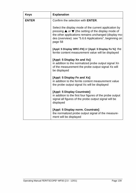
ENTER Confirm the selection with ENTER.
Select the display mode of the current application by pressing � or � (the setting of the display mode of the other applications remains unchanged (display mo-des (overview): see "5.6.6 Applications", beginning on page 58
[Appl: 5 Display WRC-FN] or [Appl: 5 Display Fe %]: the ferrite content measurement value will be displayed
[Appl: 5 Display Xn and Xs]: in addition to the normalized probe output signal Xn of the measurement the probe output signal Xs will be displayed
[Appl: 5 Display Fe and Xs]: in addition to the ferrite content measurement value the probe output signal Xs will be displayed
[Appl: 5 Display Countrate]: in addition to the first four figures of the probe output signal all figures of the probe output signal will be displayed
[Appl: 5 Display norm. Countrate]: the normalized probe output signal of the measure-ment will be displayed
Keys Explanation
Operating Manual FERITSCOPE® MP30 (2.0 - 12/01) Page 139
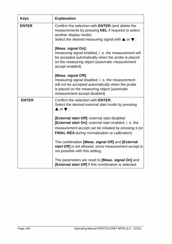
ENTER Confirm the selection with ENTER (and delete the measurements by pressing DEL if required to select another display mode).Select the desired measuring signal with � or � :
[Meas. signal On]: measuring signal enabled, i. e. the measurement will be accepted automatically when the probe is placed on the measuring object (automatic measurement accept enabled)
[Meas. signal Off]: measuring signal disabled, i. e. the measurement will not be accepted automatically when the probeis placed on the measuring object (automatic measurement accept disabled)
ENTER Confirm the selection with ENTER. Select the desired external start mode by pressing� or � :
[External start Off]: external start disabled[External start On]: external start enabled, i. e. the
measurement accept can be initiated by pressing s (or FINAL-RES during normalization or calibration)
The combination [Meas. signal Off] and [External start Off] is not allowed, since measurement accept is not possible with this setting.
The parameters are reset to [Meas. signal On] and [External start Off] if this combination is selected.
Keys Explanation
Page 140 Operating Manual FERITSCOPE® MP30 (2.0 - 12/01)
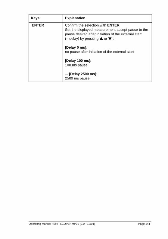
ENTER Confirm the selection with ENTER.Set the displayed measurement accept pause to the pause desired after initiation of the external start (= delay) by pressing � or � :
[Delay 0 ms]: no pause after initiation of the external start
[Delay 100 ms]: 100 ms pause
... [Delay 2500 ms]: 2500 ms pause
Keys Explanation
Operating Manual FERITSCOPE® MP30 (2.0 - 12/01) Page 141
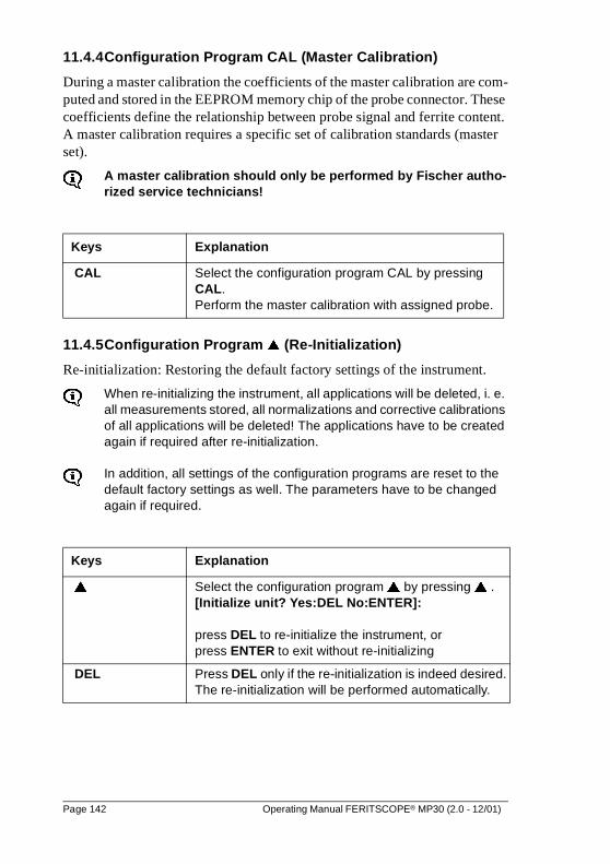
11.4.4Configuration Program CAL (Master Calibration)
During a master calibration the coefficients of the master calibration are com-puted and stored in the EEPROM memory chip of the probe connector. These coefficients define the relationship between probe signal and ferrite content. A master calibration requires a specific set of calibration standards (master set).
A master calibration should only be performed by Fischer autho-rized service technicians!
11.4.5Configuration Program � (Re-Initialization)
Re-initialization: Restoring the default factory settings of the instrument.
When re-initializing the instrument, all applications will be deleted, i. e. all measurements stored, all normalizations and corrective calibrations of all applications will be deleted! The applications have to be created again if required after re-initialization.
In addition, all settings of the configuration programs are reset to the default factory settings as well. The parameters have to be changed again if required.
Keys Explanation
CAL Select the configuration program CAL by pressing CAL. Perform the master calibration with assigned probe.
Keys Explanation
� Select the configuration program � by pressing � .[Initialize unit? Yes:DEL No:ENTER]:
press DEL to re-initialize the instrument, or press ENTER to exit without re-initializing
DEL Press DEL only if the re-initialization is indeed desired. The re-initialization will be performed automatically.
Page 142 Operating Manual FERITSCOPE® MP30 (2.0 - 12/01)
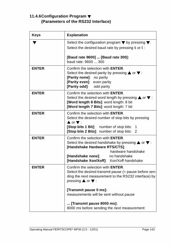
11.4.6Configuration Program � (Parameters of the RS232 Interface)
Keys Explanation
� Select the configuration program � by pressing �.
Select the desired baud rate by pressing s or t :
[Baud rate 9600] ... [Baud rate 300]: baud rate: 9600 ... 300
ENTER Confirm the selection with ENTER. Select the desired parity by pressing � or � :[Parity none]: no parity[Parity even]: even parity[Parity odd]: odd parity
ENTER Confirm the selection with ENTER.Select the desired word length by pressing � or � :[Word length 8 Bits]: word length: 8 bit[Word length 7 Bits]: word length: 7 bit
ENTER Confirm the selection with ENTER. Select the desired number of stop bits by pressing � or � :[Stop bits 1 Bit]: number of stop bits: 1[Stop bits 2 Bits]: number of stop bits: 2
ENTER Confirm the selection with ENTER.Select the desired handshake by pressing � or � :[Handshake Hardware RTS/CTS]: hardware handshake[Handshake none]: no handshake[Handshake Xon/Xoff]: Xon/Xoff handshake
ENTER Confirm the selection with ENTER. Select the desired transmit pause (= pause before sen-ding the next measurement to the RS232 interface) by pressing � or � :
[Transmit pause 0 ms]: measurements will be sent without pause
... [Transmit pause 8000 ms]:8000 ms before sending the next measurement
Operating Manual FERITSCOPE® MP30 (2.0 - 12/01) Page 143
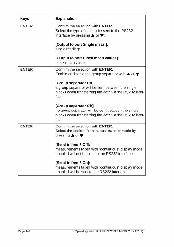
ENTER Confirm the selection with ENTER. Select the type of data to be sent to the RS232 interface by pressing � or �:
[Output to port Single meas.]: single readings
[Output to port Block mean values]: block mean values
ENTER Confirm the selection with ENTER. Enable or disable the group separator with � or � :
[Group separator On]: a group separator will be sent between the single blocks when transferring the data via the RS232 inter-face
[Group separator Off]: no group separator will be sent between the single blocks when transferring the data via the RS232 inter-face
ENTER Confirm the selection with ENTER.Select the desired “continuous” transfer mode by pressing � or � :
[Send in free ? Off]: measurements taken with “continuous” display mode enabled will not be sent to the RS232 interface
[Send in free ? On]: measurements taken with “continuous” display mode enabled will be sent to the RS232 interface
Keys Explanation
Page 144 Operating Manual FERITSCOPE® MP30 (2.0 - 12/01)
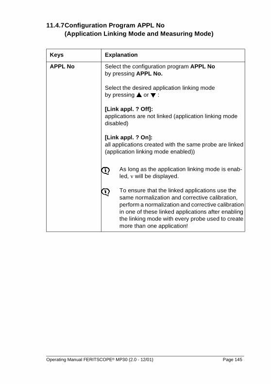
11.4.7Configuration Program APPL No (Application Linking Mode and Measuring Mode)
Keys Explanation
APPL No Select the configuration program APPL No by pressing APPL No.
Select the desired application linking mode by pressing � or � :
[Link appl. ? Off]: applications are not linked (application linking mode disabled)
[Link appl. ? On]: all applications created with the same probe are linked (application linking mode enabled))
As long as the application linking mode is enab-led, v will be displayed.
To ensure that the linked applications use the same normalization and corrective calibration, perform a normalization and corrective calibration in one of these linked applications after enabling the linking mode with every probe used to create more than one application!
Operating Manual FERITSCOPE® MP30 (2.0 - 12/01) Page 145
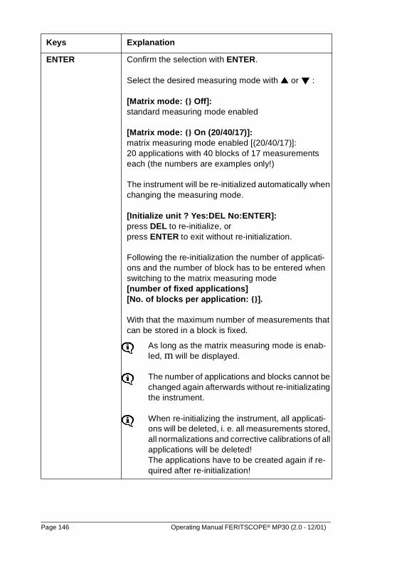
ENTER Confirm the selection with ENTER.
Select the desired measuring mode with � or � :
[Matrix mode: {} Off]: standard measuring mode enabled
[Matrix mode: {} On (20/40/17)]: matrix measuring mode enabled [(20/40/17)]: 20 applications with 40 blocks of 17 measurements each (the numbers are examples only!)
The instrument will be re-initialized automatically when changing the measuring mode.
[Initialize unit ? Yes:DEL No:ENTER]: press DEL to re-initialize, or press ENTER to exit without re-initialization.
Following the re-initialization the number of applicati-ons and the number of block has to be entered when switching to the matrix measuring mode[number of fixed applications][No. of blocks per application: {}].
With that the maximum number of measurements that can be stored in a block is fixed.
As long as the matrix measuring mode is enab-led, m will be displayed.
The number of applications and blocks cannot be changed again afterwards without re-initializating the instrument.
When re-initializing the instrument, all applicati-ons will be deleted, i. e. all measurements stored, all normalizations and corrective calibrations of all applications will be deleted! The applications have to be created again if re-quired after re-initialization!
Keys Explanation
Page 146 Operating Manual FERITSCOPE® MP30 (2.0 - 12/01)
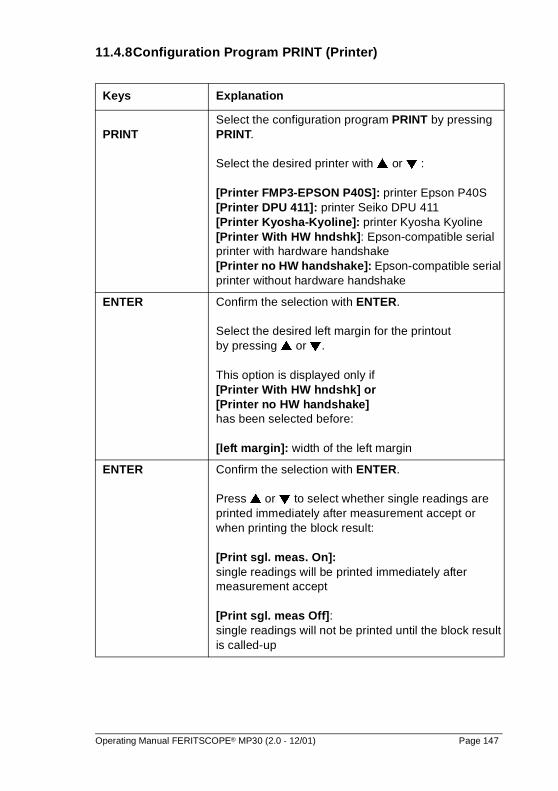
11.4.8Configuration Program PRINT (Printer)
Keys Explanation
PRINTSelect the configuration program PRINT by pressing PRINT.
Select the desired printer with � or � :
[Printer FMP3-EPSON P40S]: printer Epson P40S[Printer DPU 411]: printer Seiko DPU 411[Printer Kyosha-Kyoline]: printer Kyosha Kyoline[Printer With HW hndshk]: Epson-compatible serial printer with hardware handshake[Printer no HW handshake]: Epson-compatible serial printer without hardware handshake
ENTER Confirm the selection with ENTER.
Select the desired left margin for the printout by pressing � or �.
This option is displayed only if [Printer With HW hndshk] or [Printer no HW handshake] has been selected before:
[left margin]: width of the left margin
ENTER Confirm the selection with ENTER.
Press � or � to select whether single readings are printed immediately after measurement accept or when printing the block result:
[Print sgl. meas. On]: single readings will be printed immediately after measurement accept
[Print sgl. meas Off]: single readings will not be printed until the block result is called-up
Operating Manual FERITSCOPE® MP30 (2.0 - 12/01) Page 147
11.5 Record of the Instrument Status
Printing the Record of the Instrument Status:
A record of the instrument status without probe-specific data can be printed by pressing PRINT immediately after switching the instrument on with ON/OFF.Another way to print the record of the instrument status is to press MENU+ PRINT with the instrument switched on.
Displaying the Record of the Instrument Status:
The procedure after pressing MENU may be terminated at any time by pressing MENU again or by performing a measurement.
Keys Explanation
ENTER With the configurations programs called-up and with [FrEE] being displayed, the record of the instrument status can be printed by pressing ENTER (see figure 11.2).
The configuration programs will be exited automatical-ly and the instrument is ready to measure again.
Keys Explanation
MENU + PRINT With the instrument switched on call-up the display by pressing MENU + PRINT.
If no printer is connected, [Software version] will be displayed in the prompt lines.
With a printer connected and switched on, the record of the instrument status will be printed
�,...,� Display the next information by pressing � .
All parameters can be displayed by pressing � repeatedly.The instrument is ready to use again when all parame-ters have been printed or displayed.
Page 148 Operating Manual FERITSCOPE® MP30 (2.0 - 12/01)
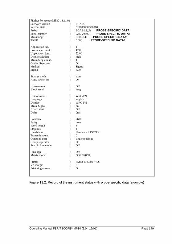
Figure 11.2: Record of the instrument status with probe-specific data (example)
Fischer Feritscope MP30 18.11.01Software version : RBA05internal state : 0x0000000D00000Probe : EGAB1.3_Fe PROBE-SPECIFIC DATA!Serial number : 0297V00001 PROBE-SPECIFIC DATA!Meas.range : 0.000-140 PROBE-SPECIFIC DATA!TKFK : 0.000 PROBE-SPECIFIC DATA!
Application No. : 1Lower spec.limit : 47.00Upper spec. limit : 52.00Disp. resolution : highMeas./Single read. : 4Outlier Rejection : OnMethod : SigmaSigma : 5.00
Storage mode : storeAuto. switch off : On
Histogramm : OffBlock result : long
Unit of meas. : WRC-FNLanguage : englishDisplay : WRC-FNMeas. Signal : onExtern start : OffDelay : 0ms
Baud rate : 9600Parity : noneWord length : 8Stop bits : 1Handshake : Hardware RTS/CTSTransmit pause : 0Outout to port : single readingsGroup seperator : OnSend in free mode : Off
Link appl : OffMatrix mode : On(20/40/17)
Printer : FMP3-EPSON P40Sleft margin : 0Print single meas. : On
Operating Manual FERITSCOPE® MP30 (2.0 - 12/01) Page 149

Page 150 Operating Manual FERITSCOPE® MP30 (2.0 - 12/01)
12 Errors
Error Possible Cause Solution
No display Instrument not switched on or instrument swit-ched itself off automatical-ly (battery save feature for operation without AC po-wer supply)
Battery discharged (when operating without AC po-wer supply)
Switch on the instrument with ON/OFF
Replace the battery or-connect the AC power supply
No results display-ed after pressing FINAL-RES
No data stored in the ap-plication (e.g. because the data were deleted)
Perform measurements
No results display-ed after pressing BLOCK-RES
No data stored in the ap-plication (e.g. because the data were deleted)
Perform measurements
No change of the display after pres-sing ZERO, CAL or MENU
Restricted operating mo-de enabled
With the instrument swit-ched off disable the rest-ricted operating mode with ON/OFF + ENTER
Applications can-not be created, overwritten or dele-ted
Restricted operating mo-de enabled
With the instrument swit-ched off disable the rest-ricted operating mode with ON/OFF + ENTER
Configuration pro-grams cannot be called-up
Restricted operating mo-de enabled
With the instrument swit-ched off disable the rest-ricted operating mode with ON/OFF + ENTER
Operating Manual FERITSCOPE® MP30 (2.0 - 12/01) Page 151
Probe does not measure
Wrong probe assigned (application was created with another probe) ([FN] or [%] flashes in the dis-play)
Automatic measurement accept disabled
Probe defective
Connect the proper probe
Enable automatic measu-rement accept in the con-figuration program ZERO orinitiate measurement accept with external start by pressing the key � (or FINAL-RES when nor-malizing or calibrating)
Replace probe
Erroneous measu-rements (continued on next page)
Measurement is influ-enced by the curvature of the measuring object, dis-tance of the measuring position to the edge, thickness of the measu-ring object or by the layer thickness
Erroneous normalization or calibration
Multiply the measured fer-rite content with the corre-sponding correction factor
Perform the normalizati-on or calibration correctly
Error Possible Cause Solution
Page 152 Operating Manual FERITSCOPE® MP30 (2.0 - 12/01)
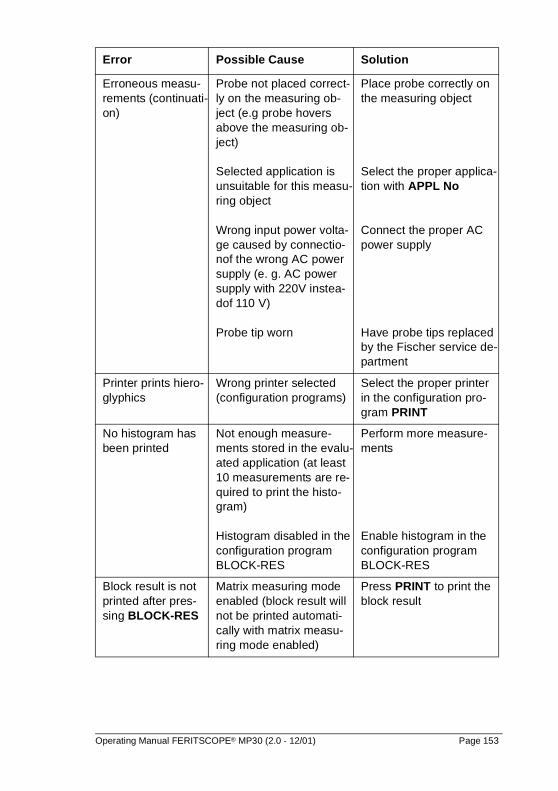
Erroneous measu-rements (continuati-on)
Probe not placed correct-ly on the measuring ob-ject (e.g probe hovers above the measuring ob-ject)
Selected application is unsuitable for this measu-ring object
Wrong input power volta-ge caused by connectio-nof the wrong AC power supply (e. g. AC power supply with 220V instea-dof 110 V)
Probe tip worn
Place probe correctly on the measuring object
Select the proper applica-tion with APPL No
Connect the proper AC power supply
Have probe tips replaced by the Fischer service de-partment
Printer prints hiero-glyphics
Wrong printer selected (configuration programs)
Select the proper printer in the configuration pro-gram PRINT
No histogram has been printed
Not enough measure-ments stored in the evalu-ated application (at least 10 measurements are re-quired to print the histo-gram)
Histogram disabled in the configuration program BLOCK-RES
Perform more measure-ments
Enable histogram in the configuration program BLOCK-RES
Block result is not printed after pres-sing BLOCK-RES
Matrix measuring mode enabled (block result will not be printed automati-cally with matrix measu-ring mode enabled)
Press PRINT to print the block result
Error Possible Cause Solution
Operating Manual FERITSCOPE® MP30 (2.0 - 12/01) Page 153
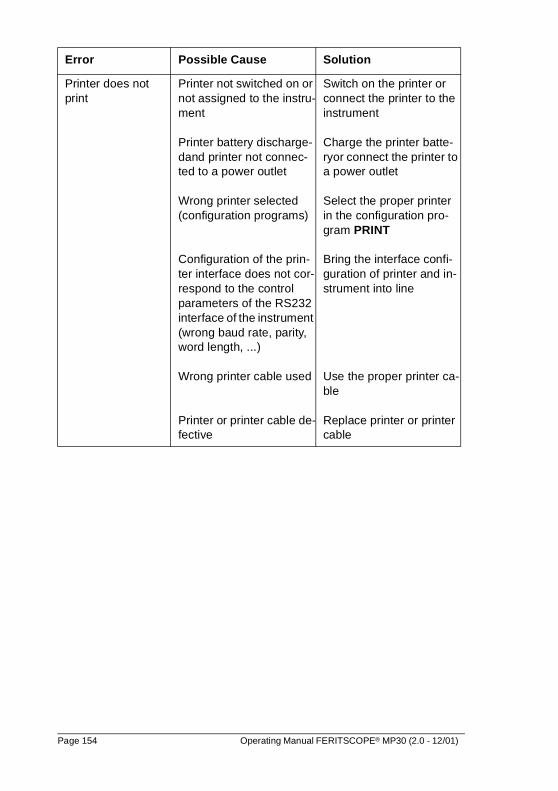
Printer does not print
Printer not switched on or not assigned to the instru-ment
Printer battery discharge-dand printer not connec-ted to a power outlet
Wrong printer selected (configuration programs)
Configuration of the prin-ter interface does not cor-respond to the control parameters of the RS232 interface of the instrument (wrong baud rate, parity, word length, ...)
Wrong printer cable used
Printer or printer cable de-fective
Switch on the printer or connect the printer to the instrument
Charge the printer batte-ryor connect the printer to a power outlet
Select the proper printer in the configuration pro-gram PRINT
Bring the interface confi-guration of printer and in-strument into line
Use the proper printer ca-ble
Replace printer or printer cable
Error Possible Cause Solution
Page 154 Operating Manual FERITSCOPE® MP30 (2.0 - 12/01)
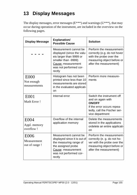
13 Display Messages
The display messages, error messages (E***) and warnings (U***), that may occur during operation of the instrument, are included in the overview on the following pages.
Display MessageExplanation/ Possible Cause
Solution
- - - -Measurement cannot be displayed (since the valu-eis larger than 9999 or smaller than -9999) Cause: measurement was not performed cor-rectly
Perform the measurement-correctly (e.g. do not hover with the probe over the measuring object before or after the measurement)
E000
Not enough measurements
Histogram has not been printed since less than 10 measurements are stored in the evaluated applicati-on
Perform more measure-ments
E001 Math Error !
Internal error Switch the instrument off and on again with ON/OFFIf the error occurs repea-tedly, call the Fischer ser-vice department
E004 Appl. memory overflow !
Overflow of the internal application memory
Delete the measurements stored in the applications ordelete an entire applicati-on
E006 Measurement out of range !
Measurement cannot be displayed since it is out of the measuring range of the assigned probe Cause: measurement was not performed cor-rectly
Perform the measurement-correctly (e. g. do not ho-ver with the probe over the measuring object before or after the measurement)
Operating Manual FERITSCOPE® MP30 (2.0 - 12/01) Page 155
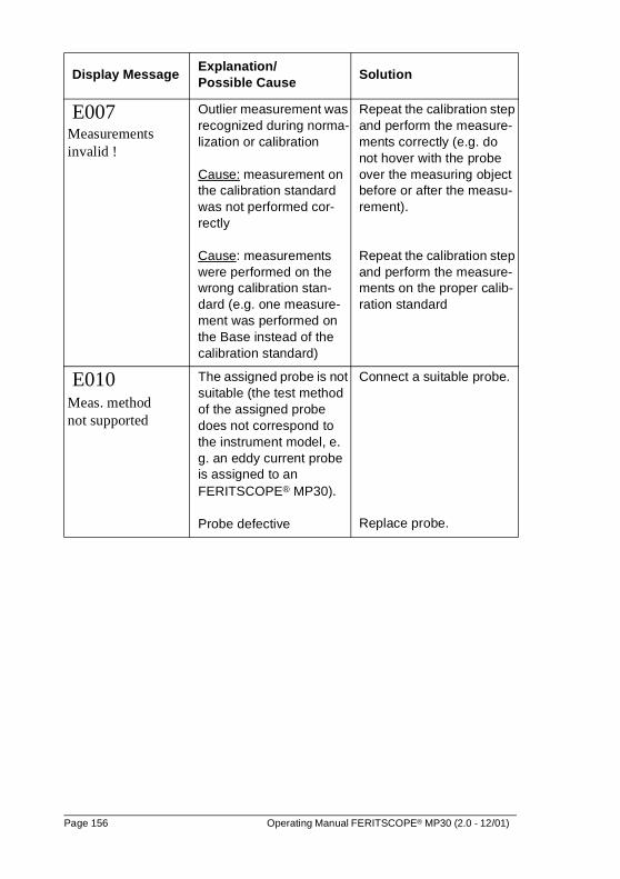
E007
Measurements invalid !
Outlier measurement was recognized during norma-lization or calibration
Cause: measurement on the calibration standard was not performed cor-rectly
Cause: measurements were performed on the wrong calibration stan-dard (e.g. one measure-ment was performed on the Base instead of the calibration standard)
Repeat the calibration step and perform the measure-ments correctly (e.g. do not hover with the probe over the measuring object before or after the measu-rement).
Repeat the calibration step and perform the measure-ments on the proper calib-ration standard
E010 Meas. method not supported
The assigned probe is not suitable (the test method of the assigned probe does not correspond to the instrument model, e. g. an eddy current probe is assigned to an FERITSCOPE® MP30).
Probe defective
Connect a suitable probe.
Replace probe.
Display MessageExplanation/ Possible Cause
Solution
Page 156 Operating Manual FERITSCOPE® MP30 (2.0 - 12/01)
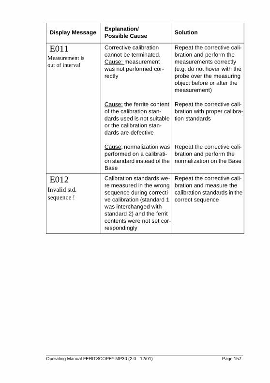
E011 Measurement is out of interval
Corrective calibration cannot be terminated.Cause: measurement was not performed cor-rectly
Cause: the ferrite content of the calibration stan-dards used is not suitable or the calibration stan-dards are defective
Cause: normalization was performed on a calibrati-on standard instead of the Base
Repeat the corrective cali-bration and perform the measurements correctly (e.g. do not hover with the probe over the measuring object before or after the measurement)
Repeat the corrective cali-bration with proper calibra-tion standards
Repeat the corrective cali-bration and perform the normalization on the Base
E012 Invalid std. sequence !
Calibration standards we-re measured in the wrong sequence during correcti-ve calibration (standard 1 was interchanged with standard 2) and the ferrit contents were not set cor-respondingly
Repeat the corrective cali-bration and measure the calibration standards in the correct sequence
Display MessageExplanation/ Possible Cause
Solution
Operating Manual FERITSCOPE® MP30 (2.0 - 12/01) Page 157
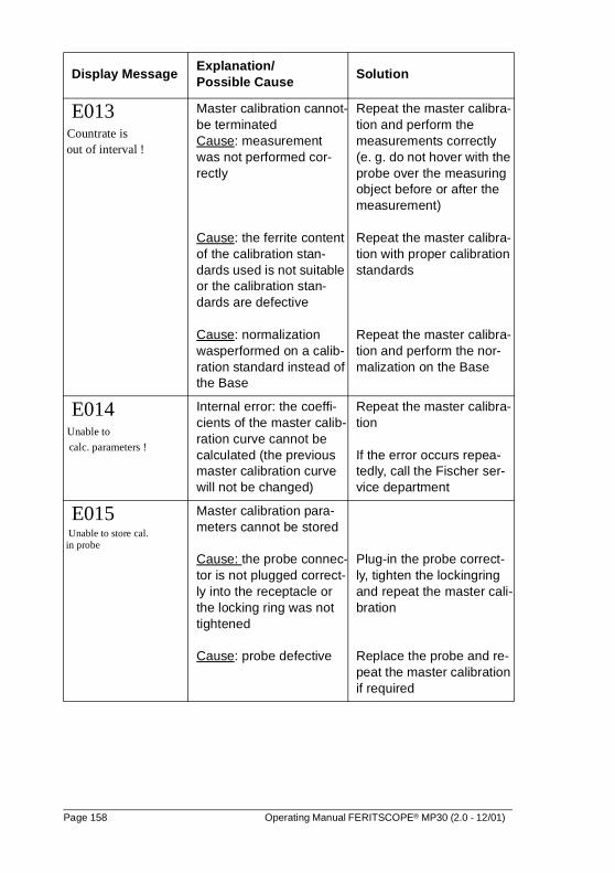
E013
Countrate is out of interval !
Master calibration cannot-be terminated Cause: measurement was not performed cor-rectly
Cause: the ferrite content of the calibration stan-dards used is not suitable or the calibration stan-dards are defective
Cause: normalization wasperformed on a calib-ration standard instead of the Base
Repeat the master calibra-tion and perform the measurements correctly (e. g. do not hover with the probe over the measuring object before or after the measurement)
Repeat the master calibra-tion with proper calibration standards
Repeat the master calibra-tion and perform the nor-malization on the Base
E014
Unable to
calc. parameters !
Internal error: the coeffi-cients of the master calib-ration curve cannot be calculated (the previous master calibration curve will not be changed)
Repeat the master calibra-tion
If the error occurs repea-tedly, call the Fischer ser-vice department
E015 Unable to store cal. in probe
Master calibration para-meters cannot be stored
Cause: the probe connec-tor is not plugged correct-ly into the receptacle or the locking ring was not tightened
Cause: probe defective
Plug-in the probe correct-ly, tighten the lockingring and repeat the master cali-bration
Replace the probe and re-peat the master calibration if required
Display MessageExplanation/ Possible Cause
Solution
Page 158 Operating Manual FERITSCOPE® MP30 (2.0 - 12/01)
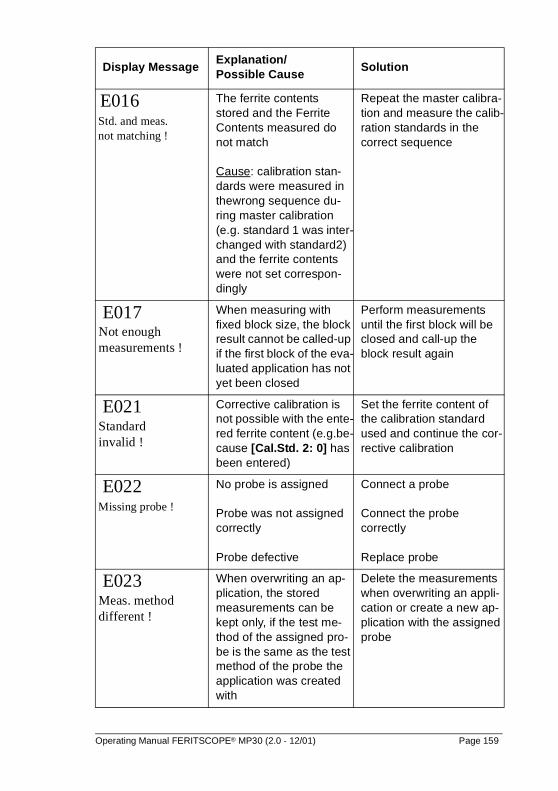
E016 Std. and meas. not matching !
The ferrite contents stored and the Ferrite Contents measured do not match
Cause: calibration stan-dards were measured in thewrong sequence du-ring master calibration (e.g. standard 1 was inter-changed with standard2) and the ferrite contents were not set correspon-dingly
Repeat the master calibra-tion and measure the calib-ration standards in the correct sequence
E017
Not enough measurements !
When measuring with fixed block size, the block result cannot be called-up if the first block of the eva-luated application has not yet been closed
Perform measurements until the first block will be closed and call-up the block result again
E021
Standard invalid !
Corrective calibration is not possible with the ente-red ferrite content (e.g.be-cause [Cal.Std. 2: 0] has been entered)
Set the ferrite content of the calibration standard used and continue the cor-rective calibration
E022 Missing probe !
No probe is assigned
Probe was not assigned correctly
Probe defective
Connect a probe
Connect the probe correctly
Replace probe
E023
Meas. method different !
When overwriting an ap-plication, the stored measurements can be kept only, if the test me-thod of the assigned pro-be is the same as the test method of the probe the application was created with
Delete the measurements when overwriting an appli-cation or create a new ap-plication with the assigned probe
Display MessageExplanation/ Possible Cause
Solution
Operating Manual FERITSCOPE® MP30 (2.0 - 12/01) Page 159
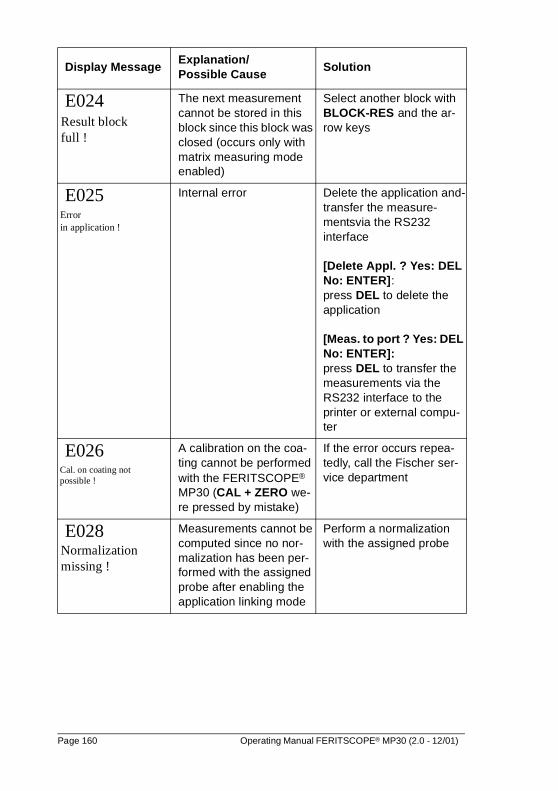
E024 Result block full !
The next measurement cannot be stored in this block since this block was closed (occurs only with matrix measuring mode enabled)
Select another block with BLOCK-RES and the ar-row keys
E025 Error in application !
Internal error Delete the application and-transfer the measure-mentsvia the RS232 interface
[Delete Appl. ? Yes: DEL No: ENTER]: press DEL to delete the application
[Meas. to port ? Yes: DEL No: ENTER]:press DEL to transfer the measurements via the RS232 interface to the printer or external compu-ter
E026 Cal. on coating not possible !
A calibration on the coa-ting cannot be performed with the FERITSCOPE® MP30 (CAL + ZERO we-re pressed by mistake)
If the error occurs repea-tedly, call the Fischer ser-vice department
E028
Normalization missing !
Measurements cannot be computed since no nor-malization has been per-formed with the assigned probe after enabling the application linking mode
Perform a normalization with the assigned probe
Display MessageExplanation/ Possible Cause
Solution
Page 160 Operating Manual FERITSCOPE® MP30 (2.0 - 12/01)
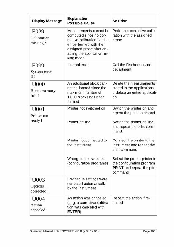
E029 Calibration missing !
Measurements cannot be computed since no cor-rective calibration has be-en performed with the assigned probe after en-abling the application lin-king mode
Perform a corrective calib-ration with the assigned probe
E999
System error !!!
Internal error Call the Fischer service department
U000 Block memory full !
An additional block can-not be formed since the maximum number of 1,000 blocks has been formed
Delete the measurements stored in the applications ordelete an entire applicati-on
U001 Printer not ready !
Printer not switched on
Printer off line
Printer not connected to the instrument
Wrong printer selected (configuration programs)
Switch the printer on and repeat the print command
Switch the printer on line and repeat the print com-mand.
Connect the printer to the instrument and repeat the print command
Select the proper printer in the configuration program PRINT and repeat the print command
U003 Options corrected !
Erroneous settings were corrected automatically by the instrument
U004
Action canceled!
An action was canceled (e. g. a corrective calibra-tion was canceled with ENTER)
Repeat the action if re-quired
Display MessageExplanation/ Possible Cause
Solution
Operating Manual FERITSCOPE® MP30 (2.0 - 12/01) Page 161
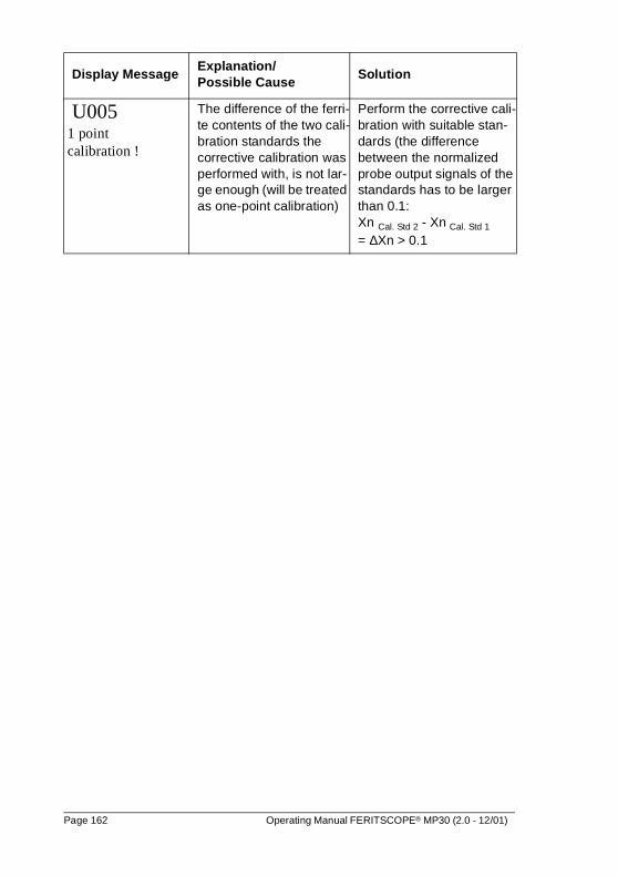
U005
1 point calibration !
The difference of the ferri-te contents of the two cali-bration standards the corrective calibration was performed with, is not lar-ge enough (will be treated as one-point calibration)
Perform the corrective cali-bration with suitable stan-dards (the difference between the normalized probe output signals of the standards has to be larger than 0.1:Xn Cal. Std 2 - Xn Cal. Std 1
= ∆Xn > 0.1
Display MessageExplanation/ Possible Cause
Solution
Page 162 Operating Manual FERITSCOPE® MP30 (2.0 - 12/01)
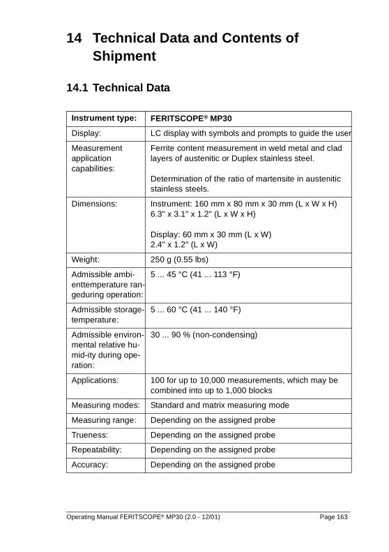
14 Technical Data and Contents of Shipment
14.1 Technical Data
Instrument type: FERITSCOPE® MP30
Display: LC display with symbols and prompts to guide the user
Measurement application capabilities:
Ferrite content measurement in weld metal and clad layers of austenitic or Duplex stainless steel.
Determination of the ratio of martensite in austenitic stainless steels.
Dimensions: Instrument: 160 mm x 80 mm x 30 mm (L x W x H)6.3" x 3.1" x 1.2" (L x W x H)
Display: 60 mm x 30 mm (L x W)2.4" x 1.2" (L x W)
Weight: 250 g (0.55 lbs)
Admissible ambi-enttemperature ran-geduring operation:
5 ... 45 °C (41 ... 113 °F)
Admissible storage-temperature:
5 ... 60 °C (41 ... 140 °F)
Admissible environ-mental relative hu-mid-ity during ope-ration:
30 ... 90 % (non-condensing)
Applications: 100 for up to 10,000 measurements, which may be combined into up to 1,000 blocks
Measuring modes: Standard and matrix measuring mode
Measuring range: Depending on the assigned probe
Trueness: Depending on the assigned probe
Repeatability: Depending on the assigned probe
Accuracy: Depending on the assigned probe
Operating Manual FERITSCOPE® MP30 (2.0 - 12/01) Page 163
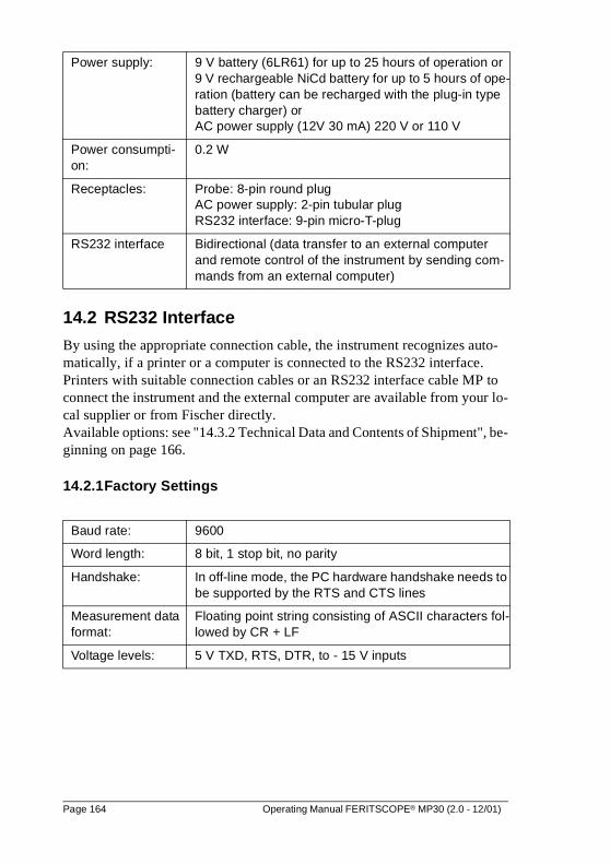
14.2 RS232 Interface
By using the appropriate connection cable, the instrument recognizes auto-matically, if a printer or a computer is connected to the RS232 interface.Printers with suitable connection cables or an RS232 interface cable MP to connect the instrument and the external computer are available from your lo-cal supplier or from Fischer directly.Available options: see "14.3.2 Technical Data and Contents of Shipment", be-ginning on page 166.
14.2.1Factory Settings
Power supply: 9 V battery (6LR61) for up to 25 hours of operation or9 V rechargeable NiCd battery for up to 5 hours of ope-ration (battery can be recharged with the plug-in type battery charger) orAC power supply (12V 30 mA) 220 V or 110 V
Power consumpti-on:
0.2 W
Receptacles: Probe: 8-pin round plugAC power supply: 2-pin tubular plugRS232 interface: 9-pin micro-T-plug
RS232 interface Bidirectional (data transfer to an external computer and remote control of the instrument by sending com-mands from an external computer)
Baud rate: 9600
Word length: 8 bit, 1 stop bit, no parity
Handshake: In off-line mode, the PC hardware handshake needs to be supported by the RTS and CTS lines
Measurement data format:
Floating point string consisting of ASCII characters fol-lowed by CR + LF
Voltage levels: 5 V TXD, RTS, DTR, to - 15 V inputs
Page 164 Operating Manual FERITSCOPE® MP30 (2.0 - 12/01)
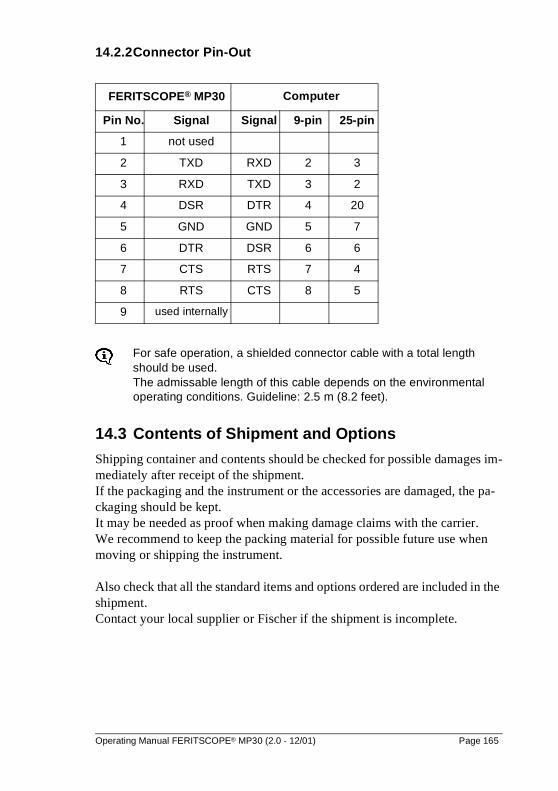
14.2.2Connector Pin-Out
For safe operation, a shielded connector cable with a total length should be used.The admissable length of this cable depends on the environmental operating conditions. Guideline: 2.5 m (8.2 feet).
14.3 Contents of Shipment and Options
Shipping container and contents should be checked for possible damages im-mediately after receipt of the shipment. If the packaging and the instrument or the accessories are damaged, the pa-ckaging should be kept. It may be needed as proof when making damage claims with the carrier.We recommend to keep the packing material for possible future use when moving or shipping the instrument.
Also check that all the standard items and options ordered are included in the shipment. Contact your local supplier or Fischer if the shipment is incomplete.
FERITSCOPE® MP30 Computer
Pin No. Signal Signal 9-pin 25-pin
1 not used
2 TXD RXD 2 3
3 RXD TXD 3 2
4 DSR DTR 4 20
5 GND GND 5 7
6 DTR DSR 6 6
7 CTS RTS 7 4
8 RTS CTS 8 5
9 used internally
Operating Manual FERITSCOPE® MP30 (2.0 - 12/01) Page 165

14.3.1 Standard Contents of an Instrument Shipment
The standard contents of an instrument shipment includes:
� Instrument in a protective plastic cover
� Battery
� Carrying and storage case
� Operator manual
� Short-form operator manual
14.3.2 Options
The following options are available:
� Additional probes
� set of calibration standards for the corrective calibration
� 9 V rechargeable NiCd battery
� 9 V alkaline battery
� Plug-in type battery recharger
� AC power supply
� desk top support for hand-held instruments
� V12 measurement stand for reproducible probe positioning
� Magnetic slide table for V12 measurement stand
� Quick loading screw fixture for V12 measurement stand to mount and measure metric and sheet metal screws
� Adapter for mounting right angle probes on the V12 measurement stand (e.g. for probe EGABW 1.3FE)
� Mounting adapter for inside probes to use with V12 measurement stand (e. g. for probe EGABI1.3-150FE mm)
� Motorized V12 measurement stand for automatic placement and lifting of probes
� FMP3 printer with cable
� Thermal paper (10 rolls) for FMP3 printer
� DKMP3-3A printer cable to connect to a Epson compatible 9-pin serial printer
� MP / RS232 interface cable with adapter for connection to an external computer (9-pin or 25-pin)
� FCC Software (Fischer Calibration and Control Software) for manage-
Page 166 Operating Manual FERITSCOPE® MP30 (2.0 - 12/01)
ment, documentation, evaluation and archiving of measurement data and measurement application specific calibrations
The instrument can only transfer measurement data to the FCC Soft-ware via the RS232 interface. It is not possible to transfer the calibrati-on parameters from the FCC Software back to the instrument!
Operating Manual FERITSCOPE® MP30 (2.0 - 12/01) Page 167

Page 168 Operating Manual FERITSCOPE® MP30 (2.0 - 12/01)
15 Correction Factors
The following factors affect the ferrite content measurement with the FERITSCOPE® MP30:
� curvature of the measuring object
� thickness of the measuring object
� layer thickness
� distance of the measuring position to the edge
The effects of these factors can be corrected for by multiplying the measured ferrite content with the corresponding correction factors.
15.1 Influence of the Curvature of the Measuring Object
The deviation of the measured ferrite content from the true ferrite content of curved measuring objects increases with increasing curvature.
The true ferrite content can be calculated as follows:
Fet = Fem · Correction factor
with: Fet true ferrite content Fem measured ferrite content
The correction factor depends on the diameter of curvature ØC of the measu-ring object and can be taken from figures 15.1 and 15.2 for convex and con-cave curvatures.
Figure 15.1 shows that convex curvatures with diameters larger than 50 mm (2") have a negligible influence. The influence of concave curvatures with di-ameters larger than 80 mm (3") is negligible (see figure 15.2).
Operating Manual FERITSCOPE® MP30 (2.0 - 12/01) Page 169
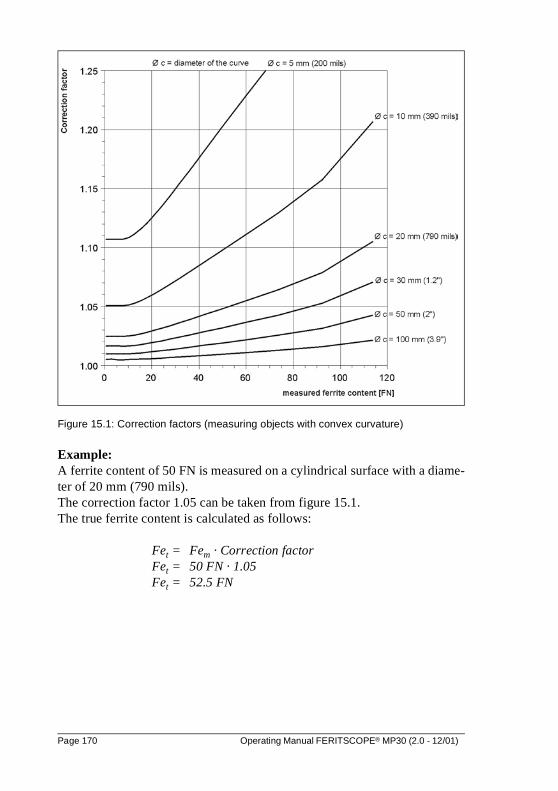
Figure 15.1: Correction factors (measuring objects with convex curvature)
Example:A ferrite content of 50 FN is measured on a cylindrical surface with a diame-ter of 20 mm (790 mils). The correction factor 1.05 can be taken from figure 15.1. The true ferrite content is calculated as follows:
Fet = Fem · Correction factorFet = 50 FN · 1.05Fet = 52.5 FN
Page 170 Operating Manual FERITSCOPE® MP30 (2.0 - 12/01)
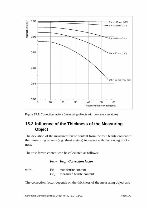
Figure 15.2: Correction factors (measuring objects with concave curvature)
15.2 Influence of the Thickness of the Measuring Object
The deviation of the measured ferrite content from the true ferrite content of thin measuring objects (e.g. sheet metals) increases with decreasing thick-ness.
The true ferrite content can be calculated as follows:
Fet = Fem · Correction factor
with: Fet true ferrite content Fem measured ferrite content
The correction factor depends on the thickness of the measuring object and
Operating Manual FERITSCOPE® MP30 (2.0 - 12/01) Page 171
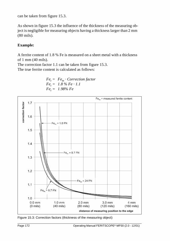
can be taken from figure 15.3.
As shown in figure 15.3 the influence of the thickness of the measuring ob-ject is negligible for measuring objects having a thickness larger than 2 mm (80 mils).
Example:
A ferrite content of 1.8 % Fe is measured on a sheet metal with a thickness of 1 mm (40 mils).The correction factor 1.1 can be taken from figure 15.3. The true ferrite content is calculated as follows:
Fet = Fem · Correction factorFet = 1.8 % Fe · 1.1Fet = 1.98% Fe
Figure 15.3: Correction factors (thickness of the measuring object)
Page 172 Operating Manual FERITSCOPE® MP30 (2.0 - 12/01)
15.3 Influence of the Layer Thickness
When measuring the ferrite content of austenitic layers the deviation of the measured ferrite content from the true ferrite content increases with decrea-sing layer thickness.
The true ferrite content can be calculated as follows:
Fet = Fem · Correction factor
with: Fet true ferrite content Fem measured ferrite content
The correction factor depends on the layer thickness and can be taken from figure 15.4.
As shown in figure 15.4 the influence of the layer thickness is negligible for measuring objects with layers which have a thickness larger than 2 mm (80 mils).
Example:A ferrite content of 3.9 % Fe is measured on a layer with a thickness of 1 mm (40 mils). The correction factor 0.75 can be taken from figure 15.4. The true ferrite content is calculated as follows:
Fet = Fem · Correction factorFet = 3.9 % Fe · 0.75Fet = 2.925% Fe
Operating Manual FERITSCOPE® MP30 (2.0 - 12/01) Page 173
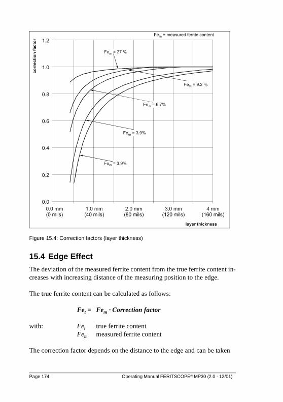
Figure 15.4: Correction factors (layer thickness)
15.4 Edge Effect
The deviation of the measured ferrite content from the true ferrite content in-creases with increasing distance of the measuring position to the edge.
The true ferrite content can be calculated as follows:
Fet = Fem · Correction factor
with: Fet true ferrite content Fem measured ferrite content
The correction factor depends on the distance to the edge and can be taken
Page 174 Operating Manual FERITSCOPE® MP30 (2.0 - 12/01)
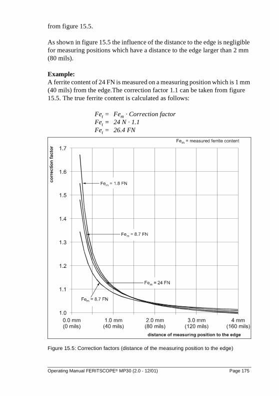
from figure 15.5.
As shown in figure 15.5 the influence of the distance to the edge is negligible for measuring positions which have a distance to the edge larger than 2 mm (80 mils).
Example:A ferrite content of 24 FN is measured on a measuring position which is 1 mm (40 mils) from the edge.The correction factor 1.1 can be taken from figure 15.5. The true ferrite content is calculated as follows:
Fet = Fem · Correction factorFet = 24 N · 1.1Fet = 26.4 FN
Figure 15.5: Correction factors (distance of the measuring position to the edge)
Operating Manual FERITSCOPE® MP30 (2.0 - 12/01) Page 175

Page 176 Operating Manual FERITSCOPE® MP30 (2.0 - 12/01)
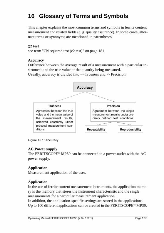
16 Glossary of Terms and Symbols
This chapter explains the most common terms and symbols in ferrite content measurement and related fields (e. g. quality assurance). In some cases, alter-nate terms or synonyms are mentioned in parentheses.
χ2 testsee term "Chi squared test (c2 test)" on page 181
AccuracyDifference between the average result of a measurement with a particular in-strument and the true value of the quantity being measured. Usually, accuracy is divided into -> Trueness and -> Precision.
Figure 16.1: Accuracy
AC Power supplyThe FERITSCOPE® MP30 can be connected to a power outlet with the AC power supply.
ApplicationMeasurement application of the user.
ApplicationIn the use of ferrite content measurement instruments, the application memo-ry is the memory that stores the instrument characteristic and the single measurements for a particular measurement application. In addition, the application-specific settings are stored in the applications. Up to 100 different applications can be created in the FERITSCOPE® MP30.
Operating Manual FERITSCOPE® MP30 (2.0 - 12/01) Page 177
It is recommended that the user create a list of application memories (e.g. in form of a table) and their uses and probes, which were used to create the ap-plication.
Attributive featuressee term "Features" on page 185
B (Bit)see term "Bit (Binary Digit)" on page 178
BaseComponent of the calibration standard set. The Base is used for normalization and corrective calibration of the FERITSCOPE® MP30. see term "Calibration standard set" on page 180.
BaudUnit of speed for transferring information via a serial port. 1 baud corresponds to a data transfer rate of 1 bit per second.
Baud rateData transfer rate. Used mainly in connection with terminal programs for se-rial data transfer. Since data are transferred via a serial port, the transfer rate is calculated in bits per second.
Bd (Baud)see term "Baud" on page 178
Bidirectional data exchangeData can be sent to and received from both participants (for example from in-strument to computer and from computer to instrument).
Bit (Binary Digit)Binary number. 1 bit is the smallest unit in the binary number system. The value of a bit is either 0 or 1. Being the smallest unit of information in a computer, a bit forms the basis of every computer system. 8 bits are combined to a byte, or several bytes to a word.
BlockSeveral measurements can be combined into a block. A closed block is indi-cated by k in the display. A block can only be closed by pressing the key BLOCK-RES or FINAL-RES followed by ENTER (or a measurement).
Page 178 Operating Manual FERITSCOPE® MP30 (2.0 - 12/01)
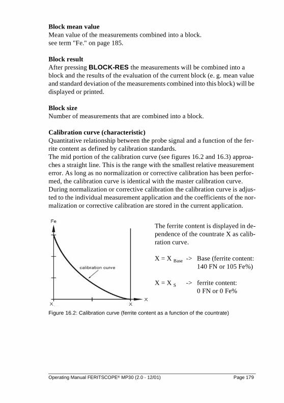
Block mean valueMean value of the measurements combined into a block.see term "Fe." on page 185.
Block resultAfter pressing BLOCK-RES the measurements will be combined into a block and the results of the evaluation of the current block (e. g. mean value and standard deviation of the measurements combined into this block) will be displayed or printed.
Block sizeNumber of measurements that are combined into a block.
Calibration curve (characteristic)Quantitative relationship between the probe signal and a function of the fer-rite content as defined by calibration standards.The mid portion of the calibration curve (see figures 16.2 and 16.3) approa-ches a straight line. This is the range with the smallest relative measurement error. As long as no normalization or corrective calibration has been perfor-med, the calibration curve is identical with the master calibration curve. During normalization or corrective calibration the calibration curve is adjus-ted to the individual measurement application and the coefficients of the nor-malization or corrective calibration are stored in the current application.
Figure 16.2: Calibration curve (ferrite content as a function of the countrate)
The ferrite content is displayed in de-pendence of the countrate X as calib-ration curve.
X = X Base -> Base (ferrite content: 140 FN or 105 Fe%)
X = X S -> ferrite content: 0 FN or 0 Fe%
Operating Manual FERITSCOPE® MP30 (2.0 - 12/01) Page 179
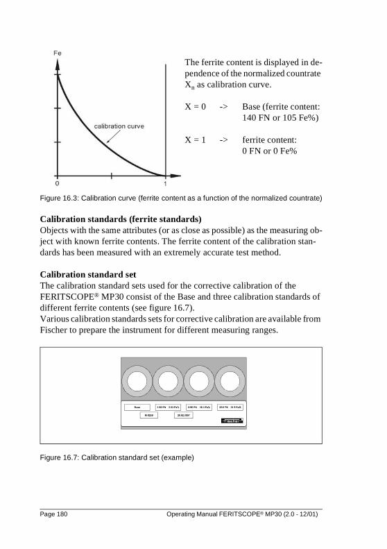
Figure 16.3: Calibration curve (ferrite content as a function of the normalized countrate)
Calibration standards (ferrite standards)Objects with the same attributes (or as close as possible) as the measuring ob-ject with known ferrite contents. The ferrite content of the calibration stan-dards has been measured with an extremely accurate test method.
Calibration standard setThe calibration standard sets used for the corrective calibration of the FERITSCOPE® MP30 consist of the Base and three calibration standards of different ferrite contents (see figure 16.7). Various calibration standards sets for corrective calibration are available from Fischer to prepare the instrument for different measuring ranges.
Figure 16.7: Calibration standard set (example)
The ferrite content is displayed in de-pendence of the normalized countrate Xn as calibration curve.
X = 0 -> Base (ferrite content: 140 FN or 105 Fe%)
X = 1 -> ferrite content: 0 FN or 0 Fe%
Page 180 Operating Manual FERITSCOPE® MP30 (2.0 - 12/01)
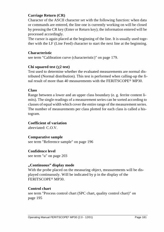
Carriage Return (CR)Character of the ASCII character set with the following function: when data or commands are entered, the line one is currently working on will be closed by pressing the CR key (Enter or Return key); the information entered will be processed accordingly. The cursor is again placed at the beginning of the line. It is usually used toge-ther with the LF (Line Feed) character to start the next line at the beginning.
Characteristicsee term "Calibration curve (characteristic)" on page 179.
Chi squared test (χ2 test)Test used to determine whether the evaluated measurements are normal dis-tributed (Normal distribution). This test is performed when calling-up the fi-nal result of more than 40 measurements with the FERITSCOPE® MP30.
ClassRange between a lower and an upper class boundary (e. g. ferrite content li-mits). The single readings of a measurement series can be sorted according to classes of equal width which cover the entire range of the measurement series. The number of measurements per class plotted for each class is called a his-togram.
Coefficient of variationabreviated: C.O.V.
Comparative samplesee term "Reference sample" on page 196
Confidence levelsee term "u" on page 203
„Continuous” display modeWith the probe placed on the measuring object, measurements will be dis-played continuously. Will be indicated by p in the display of the FERITSCOPE® MP30.
Control chartsee term "Process control chart (SPC chart, quality control chart)" on page 195
Operating Manual FERITSCOPE® MP30 (2.0 - 12/01) Page 181
Control limitsIf the measurements are entered in a process control chart, there is no need for process control measures, if the measured quantity lies within the range defi-ned by control limits.
Corrective calibration (one-point, two-point or three-point calibration)Adjustment of the instrument using a Base and one, two or three calibration standards. The corrective calibration includes calibration and adjustment.During corrective calibration the calibration curve is adjusted to the individu-al measurement application, the current application is calibrated for. The coefficients of the adjusted calibration curve are stored in the current application. The coefficients of the master calibration curve, which are stored in the EEPROM of the probe connector, remain unchanged.
CountrateDigitized form of the measurement signal, which is proportional to the ferrite content. The measurement signal is produced in the probe by the coating to be measured. The larger the ferrite content is, the larger is the countrate. see term "Calibration curve (characteristic)" on page 179.The numeric values of the normalized countrate Xn range between 0 and 1, and are calculated according to the following equation:
with:
X count rate measured on the coated measuring object
XBase: countrate measured on the Base of the calibration standard set
Xs: countrate measured on a measuring object with no ferrite content
C.O.V. (Coefficient of Variation)Also known as relative standard deviation. It is a measure of variation of a measurement series expressed in percentage points. For many coating proces-ses, C.O.V. [%] is a characteristic process constant. A change in a parameter during the coating process can alter C.O.V. [%] significantly; thus, a sudden change of indicates a change in the process conditions.
Xn
X XBase–
Xs XBase–-------------------------=
Page 182 Operating Manual FERITSCOPE® MP30 (2.0 - 12/01)
C.O.V. [%] is calculated as follows:
with:
Fe. mean value of the single measurements
s standard deviation
Cpsee term "Process capability index" on page 194.
CpkProcess capability index
CR (Carriage Return)see term "Carriage Return (CR)" on page 181.
Cumulative frequency distributionA form of display of the measurement data distribution, such that the number of measurements smaller or equal to a particular measurement is calculated and displayed in percent.
Cumulative frequency distribution chartsee term "Normal probability chart (Gaussian probability paper, cumulative frequency distribution chart, probability paper)" on page 192
CurvatureExcess and Kurtosis are measures for the curvature (e. g. how pointed or how wide) of a distribution compared to a normal distribution. A positive Kurtosis indicates a relatively narrow, pointed distribution; a negative Kurtosis indica-tes a relatively flat distribution. The Kurtosis of a normal distribution is Zero. When evaluating the current application with the FERITSCOPE® MP30, the excess will be calculated and printed after “Kurtosis”.
Data transfer ratesee term "Baud rate" on page 178
C.O.V.s
Fe..--------- 100 [%]⋅=
Operating Manual FERITSCOPE® MP30 (2.0 - 12/01) Page 183
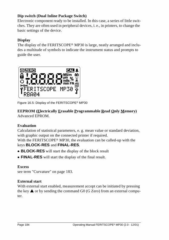
Dip switch (Dual Inline Package Switch)Electronic component ready to be installed. In this case, a series of little swit-ches. They are often used in peripheral devices, i. e., in printers, to change the basic settings of the device.
DisplayThe display of the FERITSCOPE® MP30 is large, neatly arranged and inclu-des a multitude of symbols to indicate the instrument status and prompts to guide the user.
Figure 16.5: Display of the FERITSCOPE® MP30
EEPROM (Electrically Erasable Programmable Read Only Memory)Advanced EPROM.
EvaluationCalculation of statistical parameters, e. g. mean value or standard deviation, with graphic output on the connected printer if required. With the FERITSCOPE® MP30, the evaluation can be called-up with the keys BLOCK-RES and FINAL-RES.
� BLOCK-RES will start the display of the block result
� FINAL-RES will start the display of the final result.
Excesssee term "Curvature" on page 183.
External startWith external start enabled, measurement accept can be initiated by pressing the key � or by sending the command G0 (G Zero) from an external compu-ter.
Page 184 Operating Manual FERITSCOPE® MP30 (2.0 - 12/01)
Fe.Mean value. Arithmetic mean value
Fe. of a measurement series consisting of N single readings Fei, according to the equation
with:
Fei single reading
N number of single readings evaluated
Fe..Mean value of the block mean values of the evaluated blocks (see -> Block).
with: NBl number of evaluated blocks Fe.j mean value of the j-th block
FeaturesProperties of a product. Variable features are the measurable properties of a product subject to change or variability. Ferrite content is a variable feature. Attributive features are the properties of a product that usually cannot be cap-tured by taking measurements. Examples are, deviations in color, or whether the product is true to gauge size.
Ferrite standardssee term "Calibration standards (ferrite standards)" on page 180.
Final resultEvaluation of all measurements stored in the current applications. The results of this evaluation (e.g. mean value and standard deviation) will be displayed or printed after pressing FINAL-RES.
Frequency distributionsee term "Histogram (frequency distribution)" on page 186
Fe.Fe
1Fe2 … FeN+ + +
N-----------------------------------------------------
Feii 1=
N
∑
N-------------------------==
Fe.. 1
NBl-------- Fe.j
i 1=
N
∑⋅ =
Operating Manual FERITSCOPE® MP30 (2.0 - 12/01) Page 185
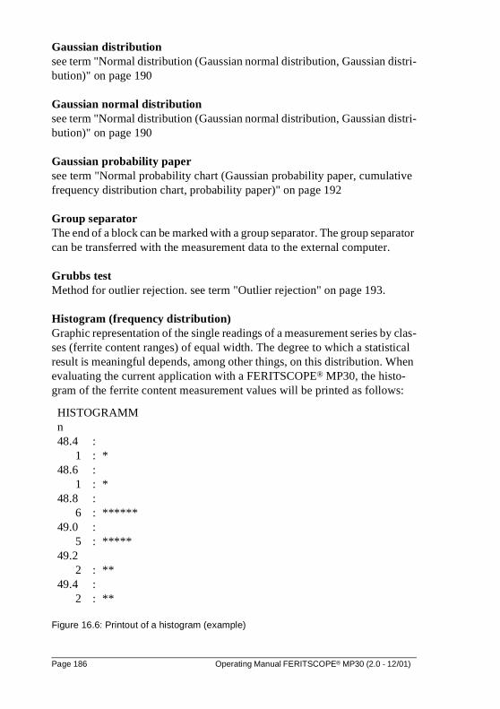
Gaussian distributionsee term "Normal distribution (Gaussian normal distribution, Gaussian distri-bution)" on page 190
Gaussian normal distributionsee term "Normal distribution (Gaussian normal distribution, Gaussian distri-bution)" on page 190
Gaussian probability papersee term "Normal probability chart (Gaussian probability paper, cumulative frequency distribution chart, probability paper)" on page 192
Group separatorThe end of a block can be marked with a group separator. The group separator can be transferred with the measurement data to the external computer.
Grubbs testMethod for outlier rejection. see term "Outlier rejection" on page 193.
Histogram (frequency distribution)Graphic representation of the single readings of a measurement series by clas-ses (ferrite content ranges) of equal width. The degree to which a statistical result is meaningful depends, among other things, on this distribution. When evaluating the current application with a FERITSCOPE® MP30, the histo-gram of the ferrite content measurement values will be printed as follows:
Figure 16.6: Printout of a histogram (example)
HISTOGRAMMn48.4 :
1 : *48.6 :
1 : *48.8 :
6 : ******49.0 :
5 : *****49.2
2 : **49.4 :
2 : **
Page 186 Operating Manual FERITSCOPE® MP30 (2.0 - 12/01)
InterfaceTransfer and connecting point between components, circuits or programs. In-terfaces are used for data transfer. Using a serial interface, the data are trans-ferred bit by bit. Using a parallel interface, the data are transferred by sending several bits simultaneously.
Kolmogorov Smirnov testTest, which is performed when evaluating the current application with the FERITSCOPE® MP30, to determine whether the evaluated measurements can be classified as having normal distribution (if up to 40 measurements are to be evaluated).
Kurtosissee term "Curvature" on page 183
Largest measurementsee term "Maximum measurement" on page 188
LF (Line Feed)see term "Line Feed (LF)" on page 187
Limitssee term "Specification limits (LSL and USL)" on page 200
Line Feed (LF)Advances the printer paper by one line. It is usually used together with the CR (Carriage Return) character to start the next line at the beginning.
Local ferrite contentThe local ferrite content is the arithmetic mean value of the single measure-ments performed on the reference area.
LSL (Lower Specification Limit)see term "Specification limits (LSL and USL)" on page 200
Master calibrationAdjustment of the instrument using a Base and calibration standards. During a master calibration, the master calibration curve is determined. The master calibration includes calibration and adjustment.
Operating Manual FERITSCOPE® MP30 (2.0 - 12/01) Page 187
Master calibration curve (probe characteristic)Characteristic of the measuring system (see -> Calibration curve)The master calibration curve is determined during master calibration on the Base and calibration standards. It is the basis for determination of the measu-rement values, since it represents the relationship between the ferrite content and the probe signal. The coefficients of the master calibration curve are stored in the EEPROM of the probe connector.
Maximum measurementLargest measurement of a measurement series.
Mean valuesee term "Fe." on page 185
MeasurementNumeric reading of an instrument, expressed in the unit of measurement.The measurement can be obtained as the result of a single measurement or as arithmetic mean of several single measurements (e. g. when measuring with “mean reading” mode enabled).
Measurement accuracysee term "Accuracy" on page 177
Measurement applicationStructure of the measuring object according to material, thickness and other properties (hard/soft, porous/dense, homogenous/inhomogenous, etc.) and any other conditions relevant to the measurement requirement. These factors determine the selection of a suitable test method and the instrument.
Measurement blocksee term "Block" on page 178.
Measurement errorsThe difference between the actual and measured value of a measured quanti-ty. For measuring instruments there is a distinction between random (unpredictable) and systematic (correctable) errors. Random errors determine the repeatability precision. Systematic (bias) errors affect the trueness and the reproducibility. Systematic errors are far more prevalent in practical ferrite content measure-ment applications (see / 7 / for further details).
Page 188 Operating Manual FERITSCOPE® MP30 (2.0 - 12/01)
Systematic (bias) errors can be traced back to:
� faulty calibration,
� operator related errors, or
� changes in test conditions (inhomogeneities of the substrate, aging, etc.).
Systematic (bias) errors tend to lean in one direction. With appropriate care, causes 1 and 2 can usually be avoided or corrected. Causes of the third kind can sometimes be eliminated by using an appropriate correction technique.
Measurement rangesee term "Measuring range" on page 190
Measurement seriesA series of single measurements made between two block or final results.Measurement system check: A significant part of monitoring the test equip-ment. Calibration standards or, even better, reference samples, are used to check the calibration and to verify the stability of the instrument.
Measurement uncertaintysee term "u" on page 203
Measuring- Measuring is comparing - The probe signal generated at the measuring position is compared to the probe signal of the calibration standard. Using the calibration curve, the instrument converts the probe signal to the measurement result.
Measuring methodsee term "Test method" on page 202
Measuring objectObject on which the measurements are to be performed to determine the fer-rite content for example.
Measuring positionA limited and clearly defined point within the reference surface of the measu-ring object where the ferrite content is to be determined. Detailed information is included in / 8 /.
Operating Manual FERITSCOPE® MP30 (2.0 - 12/01) Page 189
Measuring probesee term "Probe" on page 193
Measuring rangeThe range between the two limits within which a measurement is possible at a specified trueness and precision. In a narrower sense, it refers to the range of an analog instrument. The measuring range depends on the test method, the design of the probe, and the measurement application.
MemoryData storage element of a microprocessor-based measuring instrument. Information is saved in the memory. see term "Application" on page 177.
Methodsee term "Test method" on page 202
Minimum measurementSmallest measurement of a measurement series.
Monitoring of test equipmentA quality assurance task. It consists of ensuring that the measuring system (instrument) is operating properly and is still calibrated correctly, and to take corrective measures, if necessary (re-calibration of instrument or repair). See -> Measurement system check.
Normal distribution (Gaussian normal distribution, Gaussian distribution)Probability distribution, discovered by C. F. Gauß in 1794. If a quantity X can be classified as having normal distribution, 68.3 % of the observed values of X are within the σ-interval (σ - deviation) around the mean value µ of the quantity X, i. e. the following is valid for 68.3 % of the observed values: µ-σ ≤ X ≤ µ+σ. This interval is indicated in figure 16.7 by the grey area below the curve.
Page 190 Operating Manual FERITSCOPE® MP30 (2.0 - 12/01)
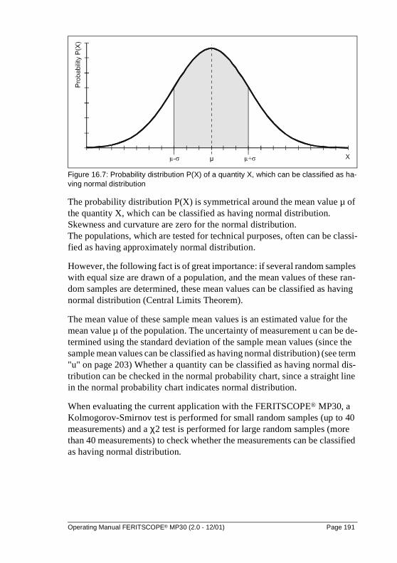
Figure 16.7: Probability distribution P(X) of a quantity X, which can be classified as ha-ving normal distribution
The probability distribution P(X) is symmetrical around the mean value µ of the quantity X, which can be classified as having normal distribution. Skewness and curvature are zero for the normal distribution. The populations, which are tested for technical purposes, often can be classi-fied as having approximately normal distribution.
However, the following fact is of great importance: if several random samples with equal size are drawn of a population, and the mean values of these ran-dom samples are determined, these mean values can be classified as having normal distribution (Central Limits Theorem).
The mean value of these sample mean values is an estimated value for the mean value µ of the population. The uncertainty of measurement u can be de-termined using the standard deviation of the sample mean values (since the sample mean values can be classified as having normal distribution) (see term "u" on page 203) Whether a quantity can be classified as having normal dis-tribution can be checked in the normal probability chart, since a straight line in the normal probability chart indicates normal distribution.
When evaluating the current application with the FERITSCOPE® MP30, a Kolmogorov-Smirnov test is performed for small random samples (up to 40 measurements) and a χ2 test is performed for large random samples (more than 40 measurements) to check whether the measurements can be classified as having normal distribution.
Operating Manual FERITSCOPE® MP30 (2.0 - 12/01) Page 191
NormalizationAdjusting a measuring instrument to a new zero value. Important for some applications when the substrate changes, or when the test method is subject to instability (e. g. to drift) (e.g. for beta backscatter and X-Ray fluorescence methods). During normalization the calibration curve is adjusted to the individual measurement application, the current application is calibrated for. The coefficients of the adjusted calibration curve are stored in the current application. The coefficients of the master calibration curve, which are stored in the EEPROM of the probe connector, remain unchanged.
Normalized countratesee term "Countrate" on page 182
Normalized probe output signalsee term "Countrate" on page 182.
Normal probability chart (Gaussian probability paper, cumulative fre-quency distribution chart, probability paper)Can be used to check graphically for normal distribution of the measure-ments. A straight line in the normal probability chart indicates normal distribution.
Off lineStatus of a peripheral device, for instance a printer or a computer, that does not allow it to receive data.
One-point calibrationsee term "Corrective calibration (one-point, two-point or three-point calibra-tion)" on page 182
On lineReady condition of a peripheral device, for instance a printer or a computer, that allows it to receive data. The connected instrument is ready for operation then.
Outlier measurementsMeasurements that are considerable larger or considerable smaller than the other measurements of the measurement series and therefore can be conside-red as unexpected or unacceptable.With outlier rejection enabled, recognized outlier measurements will be indicated by two short acoustic signals immedi-ately after measurement accept and the simultaneous appearing of d and u in
Page 192 Operating Manual FERITSCOPE® MP30 (2.0 - 12/01)
the display.
Outlier rejectionIs used to prevent the distortion of the measurement results by outlier measu-rements. With the FERITSCOPE® MP30, outlier rejection can be enabled or disabled. Measurements recognized as outliers will not be included in the evaluation. Two methods are available for outlier rejection:
� Grubbs test
� Sigma outlier rejection (entry of a known standard deviation)
ParityAn error checking method where the digits of a number must add up to an even or an odd number. During data transfer the parity bits are added to the data bits of each character to be transferred. In a word, this bit is set such that Ones of the byte always result in an even or an odd number (corresponding to an even or odd parity). The type of parity must be defined prior to the data transfer. By checking the parity, the receiver can determine if simple bit trans-fer errors occurred.
PinConnectors for integrated circuits or connecting plugs of computers and peri-pheral devices. Usually in the shape of a pin.
PrecisionAgreement between the single measurement results under precisely defined test conditions. The precision is composed of repeatability and reproducibili-ty (see -> Accuracy; see -> Repeatability; see -> Reproducibility).
Probability papersee term "Normal probability chart (Gaussian probability paper, cumulative frequency distribution chart, probability paper)" on page 192
ProbeThe instrument receives the electrical probe signal, which is proportional to the ferrite content measured, from the probe. The probe signal is then conver-ted by means of the calibration parameters into the ferrite content measure-ment value. The Fischer E... probes are equipped with a memory chip (EEPROM) in the probe connector. The EEPROM stores probe-specific in-formation (e. g. probe type, manufacturing code, test method and coefficients of the master calibration curve).
Operating Manual FERITSCOPE® MP30 (2.0 - 12/01) Page 193
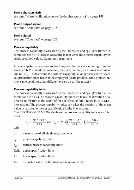
Probe characteristicsee term "Master calibration curve (probe characteristic)" on page 188
Probe output signalsee term "Countrate" on page 182
Probe signalsee term "Countrate" on page 182
Process capabilityThe process capability is assessed by the indices cp and cpk. (For further in-formation see / 4 /.) Process capability is met when the process capability ex-ceeds specified values. Commonly required is:
Process capability is a measure for long-term influences stemming from the so-called 6 Ms (mankind, machine, material, method, measuring instrument and milieu). To determine the process capability, a longer sequence of cycli-cal production steps needs to be employed (same product, same production line, same conditions, but different orders on different days).
Process capability indexThe process capability is assessed by the indices cp and cpk. (For further in-formation see / 4 /.)The process capability index cp takes the deviation of a process in relation to the width of the specification limit range (USL-LSL) into account.The process capability index cpk takes the position of the mean value in relation to the set specification limits into account.The FERITSCOPE® MP30 calculates the process capability indices as fol-lows:
with:
th. mean value of all single measurements
cp process capability index
cpk critical process capability index
USL upper specification limit
LSL lower specification limit
s^ estimated value for the standard deviation -> s^
cpUSL LSL–
6 s⋅--------------------------- and cpk Min
USL th.–3 s⋅
------------------------ ;
th. LSL–3 s⋅
----------------------- = =
Page 194 Operating Manual FERITSCOPE® MP30 (2.0 - 12/01)
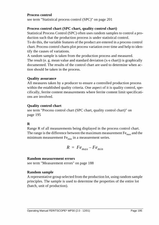
Process controlsee term "Statistical process control (SPC)" on page 201
Process control chart (SPC chart, quality control chart)Statistical Process Control (SPC) often uses random samples to control a pro-duction such that the production process is under statistical control. To do this, the variable features of the product are entered in a process control chart. Process control charts plot process variation over time and help to iden-tify the causes of variations. A random sample is taken from the production process and measured. The result (e. g. mean value and standard deviation (x-s chart)) is graphically documented. The results of the control chart are used to determine when ac-tion should be taken in the process.
Quality assuranceAll measures taken by a producer to ensure a controlled production process within the established quality criteria. One aspect of it is quality control, spe-cifically, ferrite content measurements where ferrite content limit specificati-ons are involved.
Quality control chartsee term "Process control chart (SPC chart, quality control chart)" on page 195
RRange R of all measurements being displayed in the process control chart. The range is the difference between the maximum measurement Femax and the minimum measurement Femin in a measurement series.
Random measurement errorssee term "Measurement errors" on page 188
Random sampleA representative group selected from the production lot, using random sample principles. The sample is used to determine the properties of the entire lot (batch, unit of production).
R Femax Femin–=
Operating Manual FERITSCOPE® MP30 (2.0 - 12/01) Page 195
Random sample sizeNumber of parts, combined into a random sample.
Rangesee term "R" on page 195
Reference areaA portion of the significant surface area of a product where one or more measurements are to be taken. It is recommended to include the reference area or significant surface area in the production specifications, in addition to the specifications limits for the ferrite content.
Reference measurementMeasurement on a reference sample to check the normalization or calibration which was performed before.
Reference sampleMeasuring object with a known ferrite content on a defined reference area that can be used to check the calibration. The ferrite content within the reference area should be as regular as possible. The reference sample should have the same properties (geometry, etc.) as the measuring object, the calibration is performed for. The reference samples may be from in-house production or may be from external sources. The ferrite content of a reference sample should have been determined using a reliable and properly calibrated instru-ment. Reference samples are used for the monitoring of test equipment. Reference samples are subject to wear and tear caused by the tactile measu-rement. The wear and tear is dependent on the properties of the surface and on the probe which used for measurement. For this reason, reference samples have to be checked regularly and replaced by new reference samples if the wear and tear becomes significant.
Relative standard deviationsee term "Coefficient of variation" on page 181
RepeatabilityThe standard deviation of the measurements taken under repeatability condi-tions is a measure for the repeatability. The smaller the standard deviation of these measurements, the better is repeatability. The repeatability is dependent on the test method and the quality of the instrument, but often also on the pro-perties of the measuring object (for instance, surface roughness). The standard deviation of the measurements under repeatability conditions
Page 196 Operating Manual FERITSCOPE® MP30 (2.0 - 12/01)
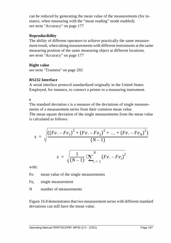
can be reduced by generating the mean value of the measurements (for in-stance, when measuring with the “mean reading” mode enabled). see term "Accuracy" on page 177
ReproducibilityThe ability of different operators to achieve practically the same measure-ment result, when taking measurements with different instruments at the same measuring position of the same measuring object at different locations. see term "Accuracy" on page 177
Right valuesee term "Trueness" on page 202
RS232 InterfaceA serial interface protocol standardized originally in the United States. Employed, for instance, to connect a printer to a measuring instrument.
sThe standard deviation s is a measure of the deviations of single measure-ments of a measurement series from their common mean value.The mean square deviation of the single measurements from the mean value is calculated as follows:
with:
Fe. mean value of the single measurements
Fei single measurement
N number of measurements
Figure 16.8 demonstrates that two measurement series with different standard deviations can still have the mean value.
sFe . Fe1–( )2
Fe. Fe2–( )2 … Fe. FeN–( )2+ + +( )
N 1–( )---------------------------------------------------------------------------------------------------------------------------=
s1
N 1–( )----------------- Fe. Fei–( )2
i 1=
N
∑⋅=
Operating Manual FERITSCOPE® MP30 (2.0 - 12/01) Page 197
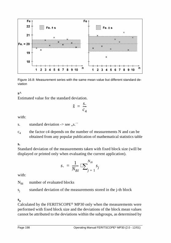
Figure 16.8: Measurement series with the same mean value but different standard de-viation
s^Estimated value for the standard deviation.
with:
s. standard deviation -> see „s.´´
c4 the factor c4 depends on the number of measurements N and can be obtained from any popular publication of mathematical statistics table
s.Standard deviation of the measurements taken with fixed block size (will be displayed or printed only when evaluating the current application).
with:
NBl number of evaluated blocks
sj standard deviation of the measurements stored in the j-th block
saCalculated by the FERITSCOPE® MP30 only when the measurements were performed with fixed block size and the deviations of the block mean values cannot be attributed to the deviations within the subgroups, as determined by
ss.c4-----=
s.1
NBl-------- sj
j 1=
NBl
∑⋅=
Page 198 Operating Manual FERITSCOPE® MP30 (2.0 - 12/01)

analysis of variance methods (A.O.V.). It describes the deviations of the block mean values in relation to the deviations of the single measurements within the blocks. With a suitable measurement strategy, sa is a measure of the product deviation.
with
sII see -> sII
Ni block size (number of measurements per block)
Estimated value for the standard deviation -> s^
s^ Estimated value for the standard deviation.
If, for instance, the same number of measurements is performed on several measuring objects and the measurements on each object are combined into a block (e. g. when measuring with fixed block size), s. is a measure for the in-strument deviation and sa is the product deviation with the instrument devia-tion eliminated.
sIIis calculated like this:
with:
NBl number of evaluated blocks
Ni block size (number of measurements per block)
Fe.. mean value of all evaluated measurements
Fe.j mean value of the measurements stored in the j-th block
Sigma outlier rejectionMethod for outlier rejection. (see term "Outlier rejection" on page 193)
sa
sII2
s2
–
Ni-------------------=
sII Ni1
NBl 1–----------------- Fe.. Fe.j–( )2
j 1=
NBl
∑⋅⋅=
Operating Manual FERITSCOPE® MP30 (2.0 - 12/01) Page 199
Significant surfaceArea on the surface of a measuring object containing the the ferrite content to be measured. All properties necessary for the use and appearance of the pro-duct must occur at this significant area.
Single measurementsee term "Single reading" on page 200
Single readingMeasurement result as displayed by the instrument after a single measure-ment at the measuring position.
SkewnessMeasure for the asymmetry of a single-peak probability distribution around its mean value. A positive skewness indicates a distribution whose peak stret-ches more towards values that are greater than the mean value. A negative skewness indicates a distribution whose peak stretches more towards values that are smaller than the mean value. The skewness of symmetric distributi-ons is zero (e. g. for normal distributions). When evaluating the current appli-cation with the FERITSCOPE® MP30, the skewness is calculated.
Smallest measurementsee term "Minimum measurement" on page 190
SPC (Statistical Process Control)see term "Statistical process control (SPC)" on page 201
SPC chartsee term "Process control chart (SPC chart, quality control chart)" on page 195
Specification limits (LSL and USL)The lower specification limit LSL is the minimum ferrite content allowed for the measuring object. The upper specification limit USL is the maximum fer-rite content allowed for the measuring object. Specification limits are usually set by engineering requirements to assure proper functioning or serviceability of the product. (see -> Specifications). With specification limits monitoring enabled, b appears in the display of the FERITSCOPE® MP30.
Page 200 Operating Manual FERITSCOPE® MP30 (2.0 - 12/01)
SpecificationsRequirements according to which production is defined within certain limits for variable and attributive properties, like for instance the lower and the up-per specification limit for the ferrite content. Quality control monitors adhe-rence to these requirements. (-> Specification limits)
Specimensee term "Measuring object" on page 189
StabilityAs with every process, test methods are also subject to deviations. This may lead to systematic measurement errors (e. g. drift), independent of handling. By examining the stability and by regular checks, one can ensure stability.
Standardsee term "Calibration standards (ferrite standards)" on page 180
Standard deviationsee term "s" on page 197
Statistical process control (SPC)A statistical method to analyze and control the quality of a process. In high volume productions, only random samples are taken instead of 100% inspec-tion which would be too costly. The measurement results of the random samples are extrapolated for the entire production lot with mathematical-sta-tistical methods, and then used to control the production process. This modern method of quality control ensures constant good quality, with a minimum le-vel of rejected parts. Normal distribution of the measurements is required so that statistical process control can be used for quality control purposes.
Stop bitWith serial asynchronous data transfer, the stop bit is added to the data word to be transferred. 1 to 2 bit logic Ones are used. After the stop bit, the sender remains at logic One until the start bit of the next character arrives.
Student distribution factorsee term "t" on page 202
Systematic measurement errorssee term "Measurement errors" on page 188
Operating Manual FERITSCOPE® MP30 (2.0 - 12/01) Page 201
tThe student distribution factor t can be obtained from any popular publication of mathematical statistics tables and is given as follows:
Example: At a confidence level of 95 % and N>200 (resulting in a degree of freedom f=199 (because of f = N-1)) the student distribution factor ist 97.5;199 = 1.96.
Test methodProcedures and process to obtain information about the properties of a measu-ring object. The test method is based on scientific findings and depends on the application. (For further details, see / 12 /.)
Three-point calibrationsee term "Corrective calibration (one-point, two-point or three-point calibra-tion)" on page 182
Tolerance limitssee term "Specification limits (LSL and USL)" on page 200
Transfer ratesee term "Baud rate" on page 178
TruenessAgreement between the true value and the mean value of the measurement re-sults, achieved constantly under practical measurement conditions. See -> Accuracy. The true value is a value known from mathematical theoretical for-mulations. Since such values are seldom encountered, a value deduced from national or international standards is taken as “right”. This right value is often indicated as true value.
True valuesee term "Trueness" on page 202
Two-point calibrationsee term "Corrective calibration (one-point, two-point or three-point calibra-tion)" on page 182
t1
α2---–
;f
Page 202 Operating Manual FERITSCOPE® MP30 (2.0 - 12/01)
uUncertainty of measurement. The mean value Fe. of a random sample is not equal to the mean value µ of the population. However it is possible to define an interval, in which the mean value µ of the population will be found with a certain probability (indicated as confidence level):
For a population having normal distribution, the uncertainty of measurement u is calculated as follows for a given confidence level (1-α):
with:
t student distribution factor
s standard deviation
N number of measurements.
By entering the coefficient of variation C.O.V. in place of the standard devi-ation s one gets the relative measurement uncertainty urel in %. For further details see / 7 /.
Uncertainty of measurementsee term "u" on page 203
Unit of measurementUnit used for the measurement display. In ferrite content measurement, the common units of measurement are ferrite numbers (FN) or point count ferrite (Fe%).
USL (Upper Specification Limit)see term "Specification limits (LSL and USL)" on page 200
Fe . u– µ Fe. u+≤ ≤
ut s⋅
N--------=
ut C.O.V.⋅
N-----------------------=
Operating Manual FERITSCOPE® MP30 (2.0 - 12/01) Page 203
Variable features
VarianceMean squared deviation. The square root of the variance is called standard deviation.
XCountrate. see term "Countrate" on page 182.
XBaseCountrate obtained when measurements are taken on the Base of the calibra-tion standard set. see term "Countrate" on page 182.
XnNormalized countrate. see term "Countrate" on page 182.
XsCountrate obtained when measuring on a measuring object with no ferrite content. see term "Countrate" on page 182.
Page 204 Operating Manual FERITSCOPE® MP30 (2.0 - 12/01)
17 Additional Literature
17.1 Statistics and Ferrite Content Measurement
/ 1 / American Welding Society 1974: Standard procedures for calibrating magnetic instruments to measure the delta ferrite content of austenitic stainless steel weld metal (AWS A4.2-74); Miami, Florida
/ 2 / DataMyte Corporation: DataMyte Handbook - A practical guide to computerized data collection for Statistical Process Control
/ 3 / Duncan, Acheson J.: Quality Control and Industrial Statistics; Homewood Illinois: Richard D. Irwin, Inc.
/ 4 / Ford Q-101: Quality System Standard
/ 5 / Helmut Fischer GmbH+Co.KG: Reports
/ 6 / Kotecki, D. J.: Extension of the WRC Ferrite Number System; Welding Research Supplement November 1982, p. 352-s ... 361-s
17.2 Standards
/ 7 / DIN 1319: Basic concepts of measurement; concepts for uncertainty of measurement and for evaluation of measuring instruments
/ 8 / DIN EN ISO 2064: Metallic and other non-organic coatings - Definitions and conventions concerning the measurement of thickness
/ 9 / DIN EN ISO 2178: Non-magnetic coatings on magnetic substrates - Measurement of coating thickness - Magnetic method
/ 10 / DIN EN ISO 2360: Non-conductive coatings on non-magnetic substrates - Measurement of coating thickness - Eddy current method
/ 11 / ISO 3534: Statistics; Vocabulary and Symbols
/ 12 / DIN EN ISO 3882: Metallic and other non-organic coatings - Review of methods of measurement of thickness
/ 13 / IIW Document II-1269-95 (II-C-034-95) - Draft Revision of ISO 8249-1985 (E) and II-C-023-94: Welding - Determination of Ferrite Number in austenitic and duplex ferritic-austenitic Cr-Ni stainless steel weld metal
/ 14 / ASTM B 244: Standard method for measurement of thickness of ano-
Operating Manual FERITSCOPE® MP30 (2.0 - 12/01) Page 205
dic coatings on aluminum and of other non-conductive coatings on nonmagnetic basis metals with eddy-current instruments
/ 15 / ASTM B 499: Standard test method for measurement of coating thick-nesses by the magnetic method: nonmagnetic coatings on magnetic basis metals
/ 16 / BS 5411: Methods of test for metallic and related coatings Part 3: Eddy current method for measurement of coating thickness of non-conductive coatings on non-magnetic basis metalsPart 11: Measurement of coating thickness of non-magnetic metallic and vitreous or porcelain enamel coatings on magnetic basis metals: magnetic method
Page 206 Operating Manual FERITSCOPE® MP30 (2.0 - 12/01)

Operating Manual FERITSCOPE® MP30 (2.0 - 12/01) Page 207
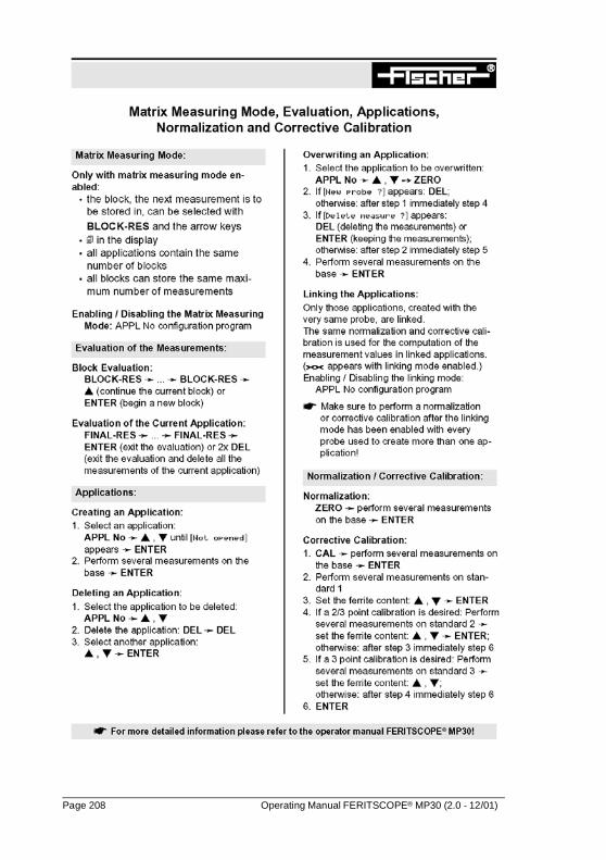
Page 208 Operating Manual FERITSCOPE® MP30 (2.0 - 12/01)
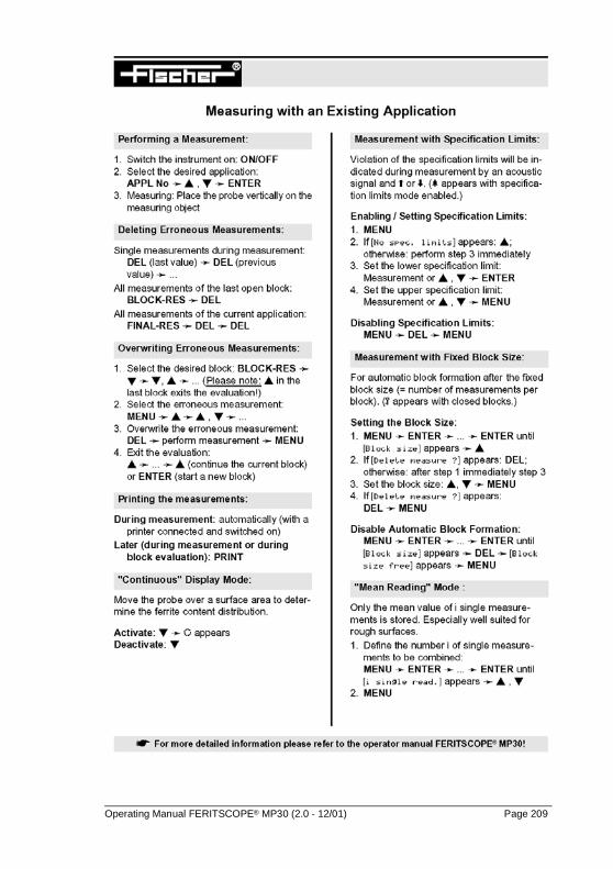
Operating Manual FERITSCOPE® MP30 (2.0 - 12/01) Page 209
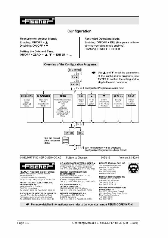
Page 210 Operating Manual FERITSCOPE® MP30 (2.0 - 12/01)

.Sales and Service Departments - all around the world -
GERMANYHELMUT FISCHER GMBH+CO.KGIndustriestrasse 21D-71069 Sindelfingen�: (+49) 7031-303-0Fax: (+49) [email protected]: Helmut-Fischer.com
GREAT BRITAINFISCHER INSTRUMENTATION (G.B.) LTD.Gordleton Industrial ParkHannah Way · PenningtonGB-Lymington/Hants SO41 8JD�: (+44) 15 90-68 36 63Fax: (+44) 15 90-68 41 [email protected]: fischergb.co.uk
USAFISCHER TECHNOLOGY, INC.750 Marshall Phelps Road Windsor, CT 06095 USA�: 860-683-0781Fax: 860-688-8496Watts 800-243-8417info@fischer-technology. comInternet: fischer-technology.com
Sole Agent for Helmut Fischer GmbH+Co.KG, Germany:
SWITZERLANDHELMUT FISCHER Elektronik und Messtechnik AGMoosmattstrasse 1 · Postfach · CH-6331 Hünenberg�: (+41) 41 785 08 00 · Fax: (+41) 41 785 08 [email protected]
Branch Offices of Helmut Fischer AG, Switzerland:
SPAINFISCHER INSTRUMENTS, S.A.C/Almogàvers 157 · 3a PlantaE-08018 Barcelona�: (+34) 93 309 79 16Fax: (+34) 93 485 05 [email protected]
ITALYHELMUT FISCHER S.R.L. Tecnica di Misura Via Columella 40 · I-20128 Milano�: (+39) 02 255 26 26Fax: (+39) 02 257 00 [email protected]
JAPANFISCHER INSTRUMENTS K.K.Shinmei 2-3-5 · Souka-shiSaitama-ken 340 · Japan�: (+81) 489 32 3621Fax: (+81) 489 32 [email protected]
FRANCEFISCHER INSTRUMENTATION ELECTRONIQUEParc d'Activités Nord du Pas du Lac · 5, rue Michaël FaradayF-78180 Montigny le BretonneuxBP 289 · F-78053 St Quentin en Yvelines Cedex�: (+33) (0) 1 30 58 00 58Fax: (+33) (0) 1 30 58 89 [email protected]
HONG KONGFISCHER INSTRUMENTATION (FAR EAST) LTD.Unit 2901 · Level 29Metroplaza Tower 2223 Hing Fong RoadKwai Chung, N.T.Hong Kong�: (+852) 24 20 11 00Fax: (+852) 24 87 02 [email protected]/www.helmut-fischer.com
THE NETHERLANDSHELMUT FISCHER MEETTECHNIEK B.V.Tarasconweg 10NL-5627 GB EindhovenPostbus 1828NL-5602 CA Eindhoven�: (+31) 40 248 22 55Fax: (+31) 40 242 88 [email protected]
CHINANANTONG FISCHER INSTRUMENTATION LTD.7F, No. 2 Building2601 Songhuajiang RoadShanghai 200437 · P.R.C.�: (+86) 21 6555 7455 Fax: (+86) 21 6555 [email protected]
SINGAPOREFISCHER INSTRUMENTATION (S) PTE LTD.102 E Pasir Panjang Road #04-04Citilink Warehouse ComplexSingapore 118529�: (+65) 276 67 76Fax: (+65) 276 76 [email protected]
Valid for Helmut Fischer AG and Branch Offices
Operating Manual FERITSCOPE® MP30 (2.0 - 12/01) Page 211

Page 212 Operating Manual FERITSCOPE® MP30 (2.0 - 12/01)


![脈動テストポンプMP30脈動テストポンプMP30 [ご使用前には必ず本書をお読みください。] 取扱説明書](https://img.pdfslide.net/doc/110x75/5fe6a5852e55f209df60323a/efffffmp30-efffffmp30-coee.jpg)