Embed Size (px)
Citation preview
1
FNALFNAL--NICADD extruded NICADD extruded scintillatorscintillator
Presented by Victor Rykalin
Rome 1 , October 2004
FERMILAB
2
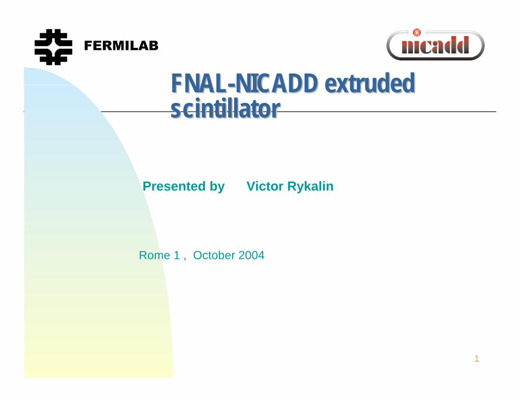
FNAL-NICADD EXTRUSION FACILITY
•In-line continuous process:
•Less handling of raw materials
•Precise metering of feeders
•Twin-screw extruder (better mixing)
•Melt pump offers steady output
•Control instrumentation
•Line under nitrogen atmosphere:
•Drying under nitrogen
•Each piece of equipment is purged
POLYMERDRYER
CONVEYOR
POLYMER FEEDER
DOPANT FEEDER
EXTRUDER
MELT PUMP
DIE
OUTPUT:
Scintillating pelletsScintillator bars
3
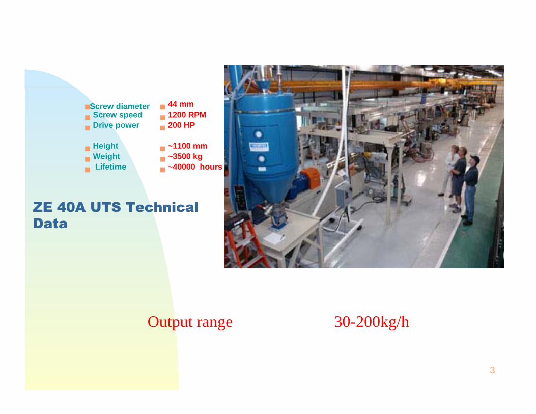
ZE 40A UTS Technical Data
Screw diameterScrew speedDrive power
HeightWeightLifetime
44 mm1200 RPM200 HP
~1100 mm~3500 kg~40000 hours
Output range 30-200kg/h
4
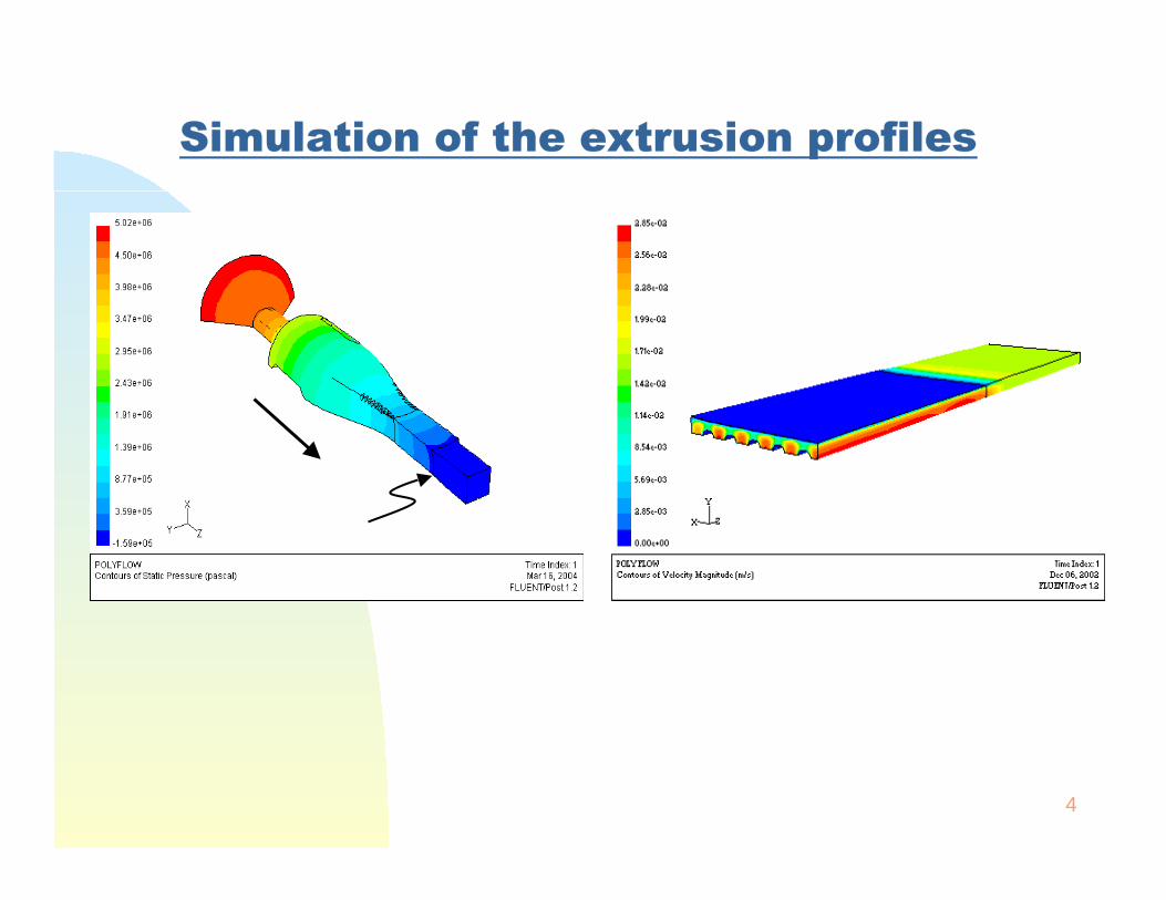
Simulation of the extrusion profiles
5
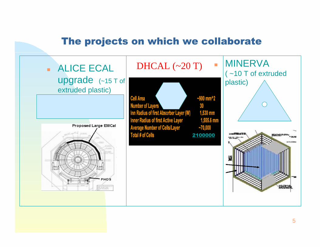
The projects on which we collaborate
ALICE ECAL upgrade (~15 T ofextruded plastic)
MINERVA ( ~10 T of extruded plastic)
DHCAL (~20 T)
2100000
6
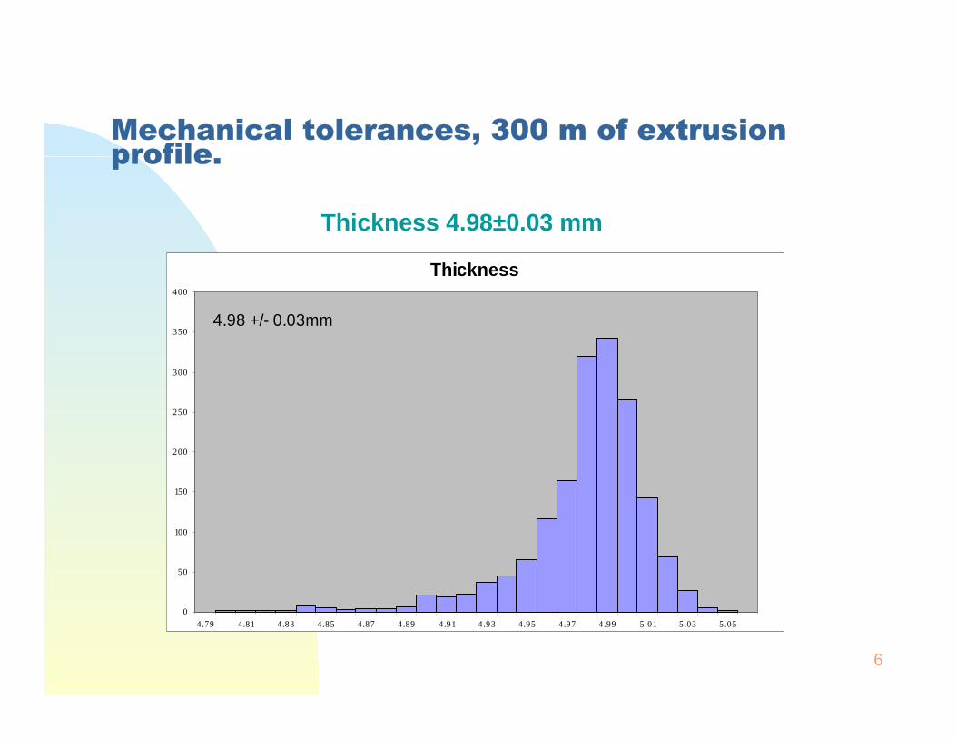
Mechanical tolerances, 300 m of extrusion profile.
Thickness 4.98±0.03 mm
Thickness
0
50
100
150
200
250
300
350
400
4.79 4.81 4.83 4.85 4.87 4.89 4.91 4.93 4.95 4.97 4.99 5.01 5.03 5.05
4.98 +/- 0.03mm
7
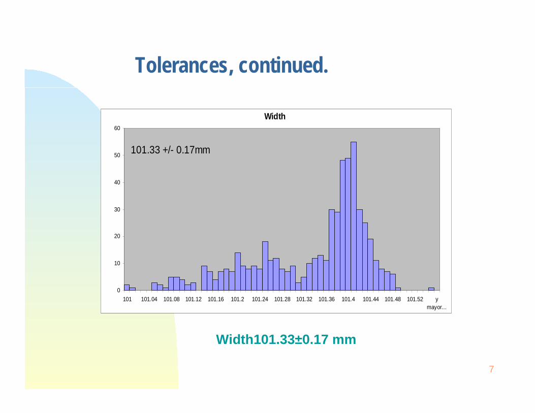
Tolerances, continued.
Width
0
10
20
30
40
50
60
101 101.04 101.08 101.12 101.16 101.2 101.24 101.28 101.32 101.36 101.4 101.44 101.48 101.52 ymayor...
101.33 +/- 0.17mm
Width101.33±0.17 mm
8
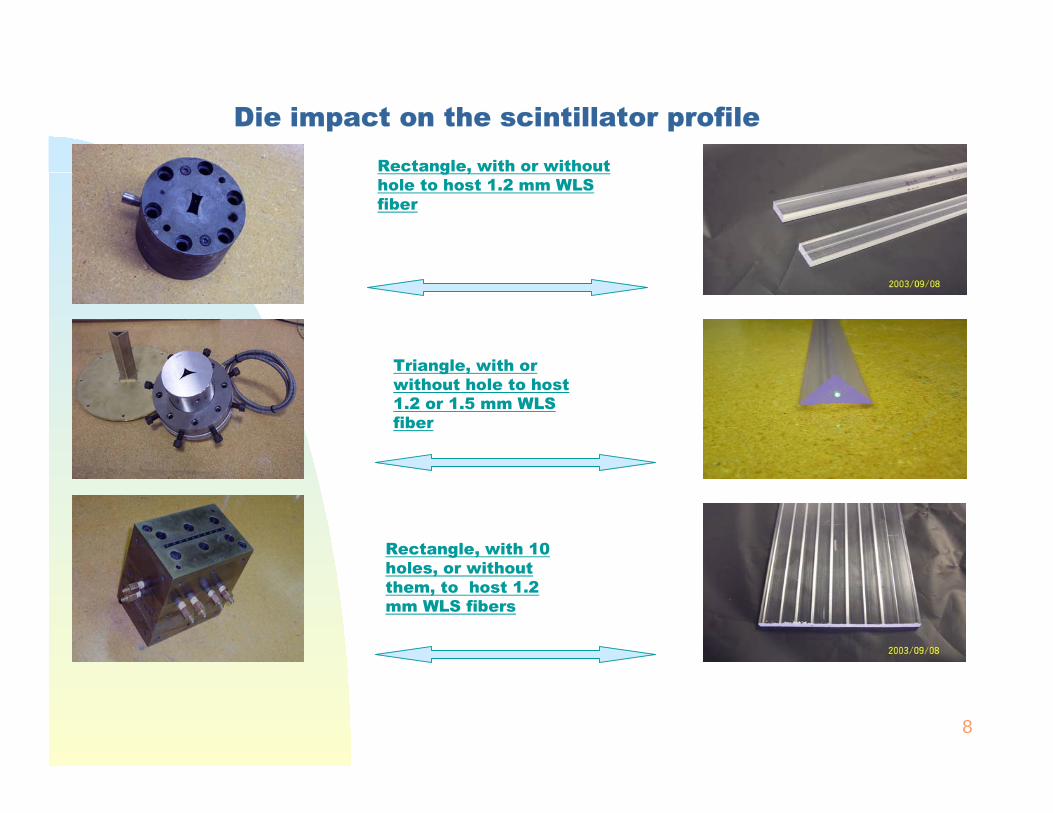
Die impact on the scintillator profile
Rectangle, with or without hole to host 1.2 mm WLS fiber
Triangle, with or without hole to host 1.2 or 1.5 mm WLS fiber
Rectangle, with 10 holes, or without them, to host 1.2 mm WLS fibers
9
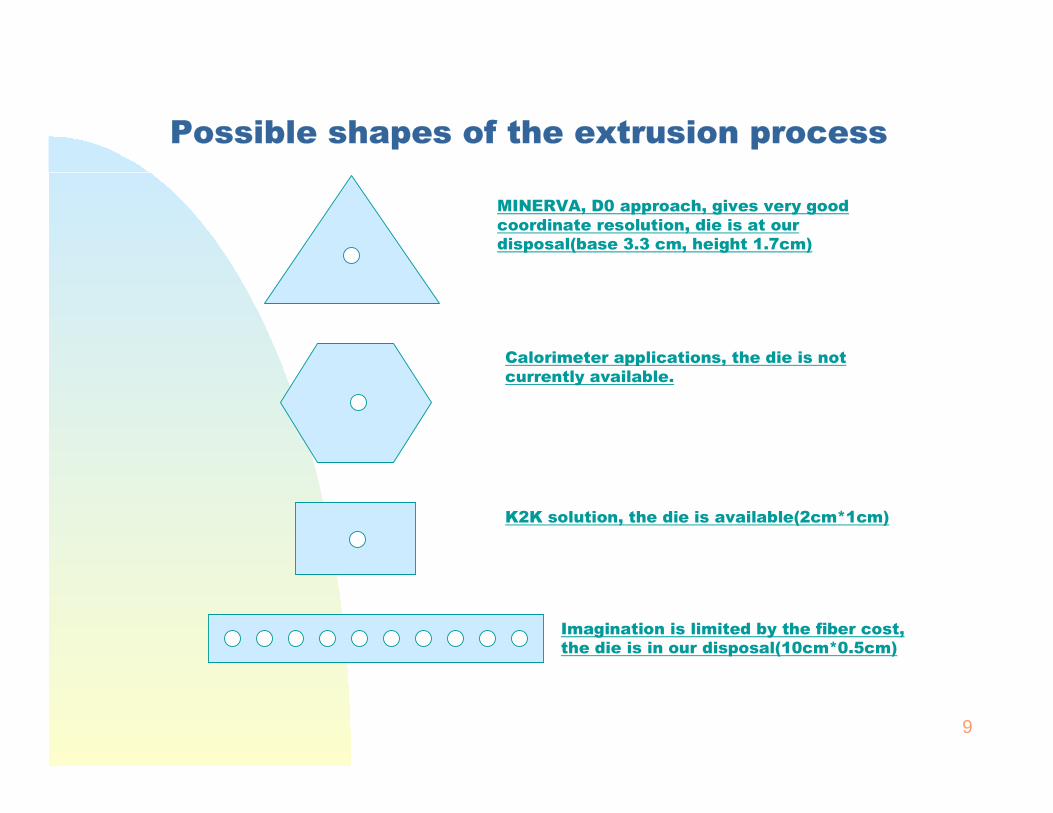
Possible shapes of the extrusion process
MINERVA, D0 approach, gives very good coordinate resolution, die is at our disposal(base 3.3 cm, height 1.7cm)
Calorimeter applications, the die is not currently available.
K2K solution, the die is available(2cm*1cm)
Imagination is limited by the fiber cost, the die is in our disposal(10cm*0.5cm)
10
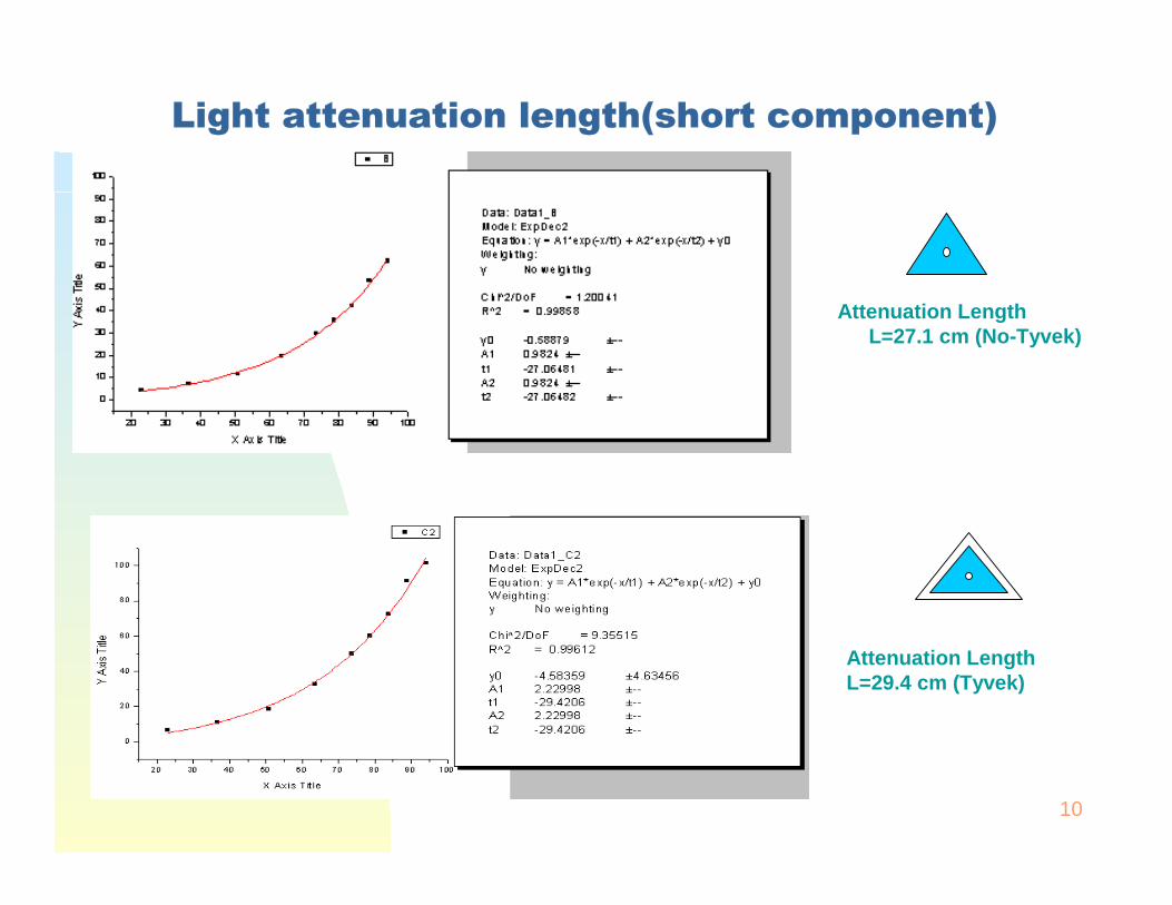
Attenuation LengthL=27.1 cm (No-Tyvek)
Attenuation Length L=29.4 cm (Tyvek)
Light attenuation length(short component)
11
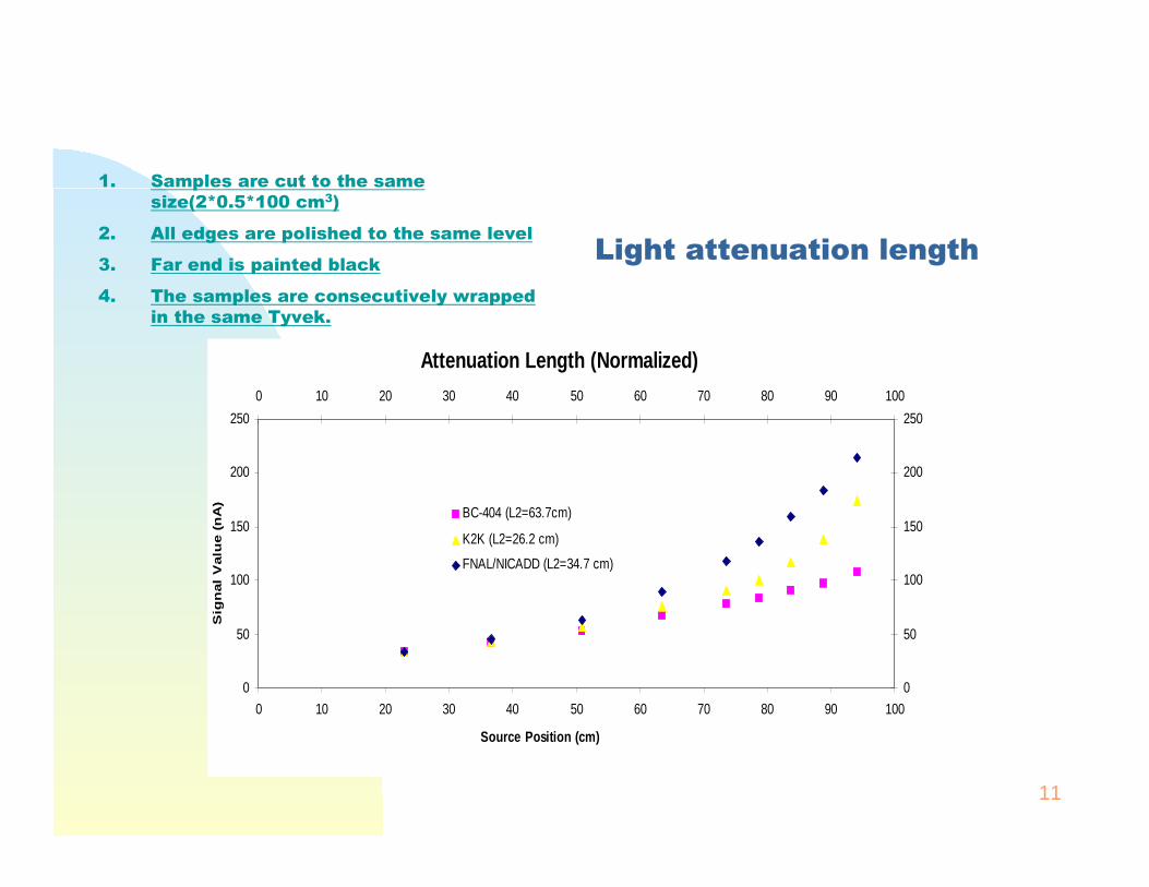
Light attenuation length
1. Samples are cut to the same size(2*0.5*100 cm3)
2. All edges are polished to the same level
3. Far end is painted black
4. The samples are consecutively wrapped in the same Tyvek.
Attenuation Length (Normalized)
0
50
100
150
200
250
0 10 20 30 40 50 60 70 80 90 100
Source Position (cm)
Sig
nal
Valu
e (
nA
)
0
50
100
150
200
250
0 10 20 30 40 50 60 70 80 90 100
BC-404 (L2=63.7cm)
K2K (L2=26.2 cm)
FNAL/NICADD (L2=34.7 cm)
12
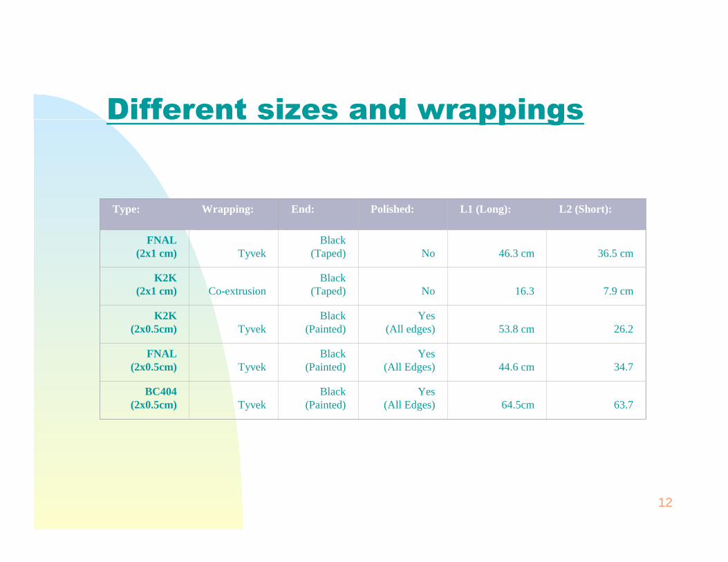
Type: Wrapping: End: Polished: L1 (Long): L2 (Short):
FNAL(2x1 cm) Tyvek
Black(Taped) No 46.3 cm 36.5 cm
K2K(2x1 cm) Co-extrusion
Black(Taped) No 16.3 7.9 cm
K2K(2x0.5cm) Tyvek
Black(Painted)
Yes(All edges) 53.8 cm 26.2
FNAL(2x0.5cm) Tyvek
Black(Painted)
Yes(All Edges) 44.6 cm 34.7
BC404(2x0.5cm) Tyvek
Black(Painted)
Yes(All Edges) 64.5cm 63.7
Different sizes and wrappings
13
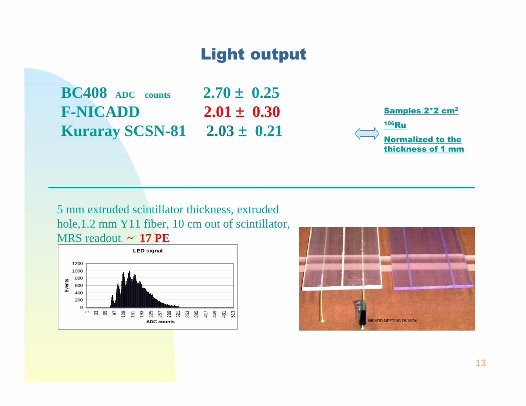
Light output
Samples 2*2 cm2
106Ru
Normalized to the thickness of 1 mm
BC408 ADC counts 2.70 ± 0.25 F-NICADD 2.01 ± 0.30Kuraray SCSN-81 2.03 ± 0.21
5 mm extruded scintillator thickness, extruded hole,1.2 mm Y11 fiber, 10 cm out of scintillator, MRS readout ~ 17 PE
LED signal
0
200
400
600
800
1000
1200
1 33 65 97 129
161
193
225
257
289
321
353
385
417
449
481
513
ADC counts
Even
ts
14
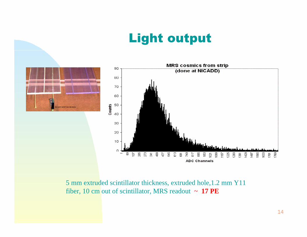
5 mm extruded scintillator thickness, extruded hole,1.2 mm Y11 fiber, 10 cm out of scintillator, MRS readout ~ 17 PE
Light output
15
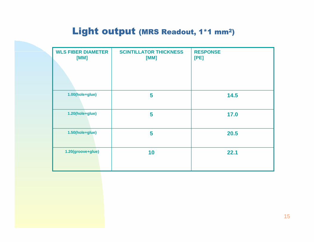
Light output (MRS Readout, 1*1 mm2)
22.1101.20(groove+glue)
20.551.50(hole+glue)
17.051.20(hole+glue)
14.551.00(hole+glue)
RESPONSE[PE]
SCINTILLATOR THICKNESS [MM]
WLS FIBER DIAMETER [MM]
16
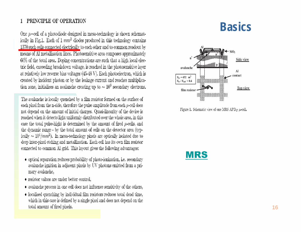
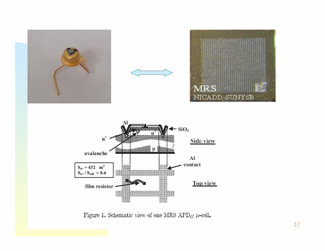
Basics
MRS
17
18
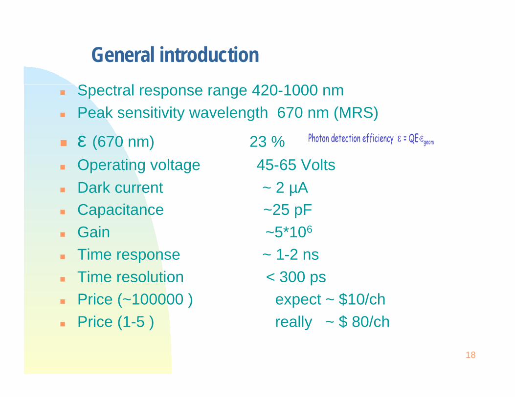
General introduction
Spectral response range 420-1000 nmPeak sensitivity wavelength 670 nm (MRS)
ε (670 nm) 23 %
Operating voltage 45-65 Volts
Dark current ~ 2 µACapacitance ~25 pFGain ~5*106
Time response ~ 1-2 nsTime resolution < 300 psPrice (~100000 ) expect ~ $10/chPrice (1-5 ) really ~ $ 80/ch

19
Tested PC board + MRS
0
400
800
1200
1600
1 61 121 181 241 301 361 421 481
ACD Channe ls
Co
un
ts
0
500
1000
1500
2000
1 61 121 181 241 301 361 421 481
ACD Channe ls
Co
un
ts
0
250
500
750
1000
1 61 121 181 241 301 361 421 481
ACD Channe ls
Co
un
ts
0
250
500
750
1000
1 61 121 181 241 301 361 421 481
ACD Channe ls
Co
un
ts
0
250
500
750
1000
1 61 121 181 241 301 361 421 481
ACD Channe ls
Co
un
ts
0
200
400
600
800
1 61 121 181 241 301 361 421 481
ACD Channe ls
Co
un
ts
0
250
500
750
1000
1 61 121 181 241 301 361 421 481
ACD Channe ls
Co
un
ts
20
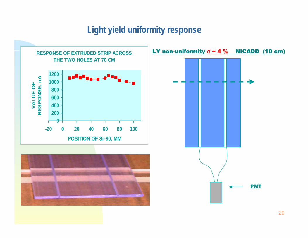
Light yield uniformity response
RESPONSE OF EXTRUDED STRIP ACROSS THE TWO HOLES AT 70 CM
0200400600800
10001200
-20 0 20 40 60 80 100
POSITION OF Sr-90, MM
VA
LU
E O
F
RE
SP
ON
SE
, n
A
LY non-uniformity σ ~ 4 % NICADD (10 cm)
PMT
21
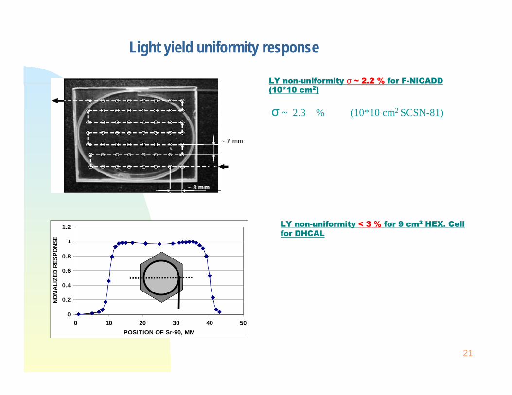
Light yield uniformity response
LY non-uniformity σ ~ 2.2 % for F-NICADD (10*10 cm2)
0
0.2
0.4
0.6
0.8
1
1.2
0 10 20 30 40 50
POSITION OF Sr-90, MM
NO
MA
LIZE
D R
ES
PO
NS
E
LY non-uniformity < 3 % for 9 cm2 HEX. Cell for DHCAL
σ ~ 2.3 % (10*10 cm2 SCSN-81)
22
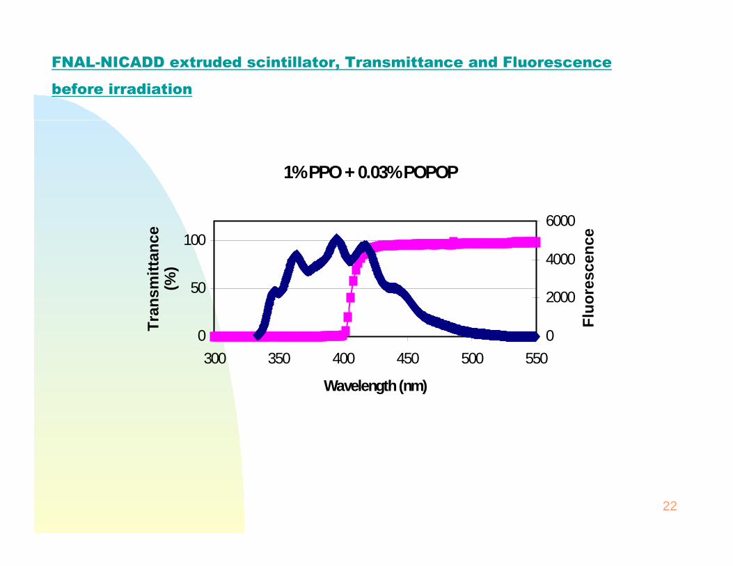
FNAL-NICADD extruded scintillator, Transmittance and Fluorescence
before irradiation
1% PPO + 0.03% POPOP
0
50
100
300 350 400 450 500 550
Wavelength (nm)
Tra
nsm
itta
nce
(%
)
0
2000
4000
6000
Flu
ore
scen
ce
23
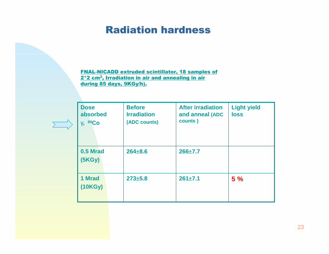
Radiation hardness
5 %261±7.1273±5.81 Mrad(10KGy)
266±7.7264±8.60.5 Mrad(5KGy)
Light yield loss
After irradiation and anneal (ADC counts )
Before Irradiation(ADC counts)
Dose absorbedγ, 60Co
FNAL-NICADD extruded scintillator, 18 samples of 2*2 cm2, Irradiation in air and annealing in air during 85 days, 9KGy/h).
24
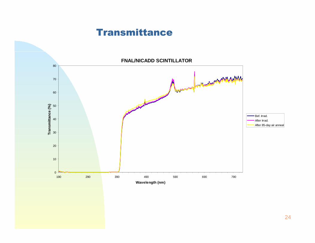
Transmittance
FNAL/NICADD SCINTILLATOR
0
10
20
30
40
50
60
70
80
190 290 390 490 590 690 790
Wavelength (nm)
Tra
nsm
itta
nce
(%
)
Bef. Irrad.
After Irrad.
After 85-day air anneal
25
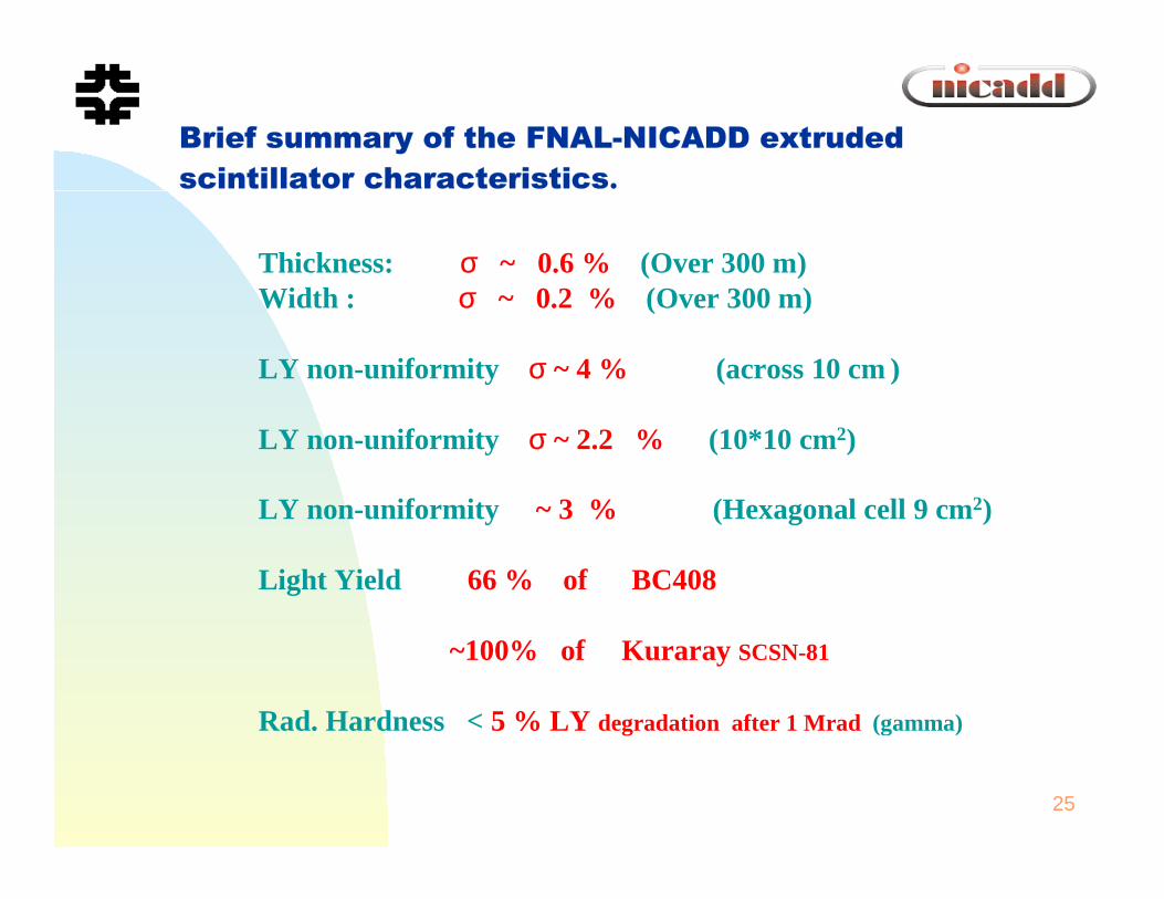
Thickness: σ ~ 0.6 % (Over 300 m)Width : σ ~ 0.2 % (Over 300 m)
LY non-uniformity σ ~ 4 % (across 10 cm )
LY non-uniformity σ ~ 2.2 % (10*10 cm2)
LY non-uniformity ~ 3 % (Hexagonal cell 9 cm2)
Light Yield 66 % of BC408
~100% of Kuraray SCSN-81
Rad. Hardness < 5 % LY degradation after 1 Mrad (gamma)
Brief summary of the FNAL-NICADD extruded scintillator characteristics.