Embed Size (px)
Citation preview

FERRO-THERMSTEEL PIPING SYSTEM
FERRO-THERMTHERMACOR’S FERRO-THERM is a factory-fabricated, pre-insulated piping system for below or above ground distribution of hot and chill water, low pressure steam, condensate, or oil and viscous fluids. The system is designed with a steel carrier pipe (type and grade specified, as required), closed cell polyure-thane foam insulation, and a High Density Polyethylene (HDPE) jacket.
Carrier Pipe • d > 2” - A53 ERW Grade B, Std. Wt. Black Steel • d < 2” - A106 SML, Std. Wt. Black Steel • Seamless & Schedule 80 pipe are available for all sizes. • Std. Wt. is the same as Schedule 40 through 10”. • XS is the same as Schedule 80 through 8”
Polyurethane Insulation • Density > 2.0 lbs/ft³ • “K” Factor < 0.16 @ 75°F • Compressive Strength > 30 psi • Closed Cell Content > 90% @ 75°F
Jacket • High Density Polyethylene (HDPE)
20' or 40' RANDOM LENGTHS
6" TYP. Polyurethane InsulationHDPE Jacket
Carrier Piped
P.O. BOX 79670 · 1670 HICKS FIELD ROAD EAST · FORT WORTH, TEXAS 76179 · 817 / 847-7300 · FAX 817 / 847-7222
THERMACOR

The information contained in this document is subject to change without notice. THERMACOR PROCESS INC. believes the information contained herein to be reliable, but makes no representations as to its accuracy or completeness.
THERMACOR PROCESS INC. sole and exclusive warranty is as stated in the Standard Terms and Conditions of Sale forthese products. In no event will THERMACOR PROCESS INC. be liable for any direct, indirect, or consequential damage.
THERMACOR PROCESS INC. Your Authorized THERMACOR Representative Is:
SPECIFICATION GUIDE *GENERALAll underground and above ground piping materials transporting chill water, hot water, low-pressure steam (250°F) or condensate shall be FERRO-THERM as manufactured by THERMACOR PROCESS INC. All straight pipe, fittings, anchors, insulating materials, and technical support shall be provided by the manu-facturer.
SERVICE PIPEThe carrier or service pipe shall be A-53, Grade B, ERW, Standard Weight for pipe sizes 2” and larger and A106/ A53, Grade B, seamless, standard weight for pipe sizes 1.5” and smaller. Condensate piping mate-rials shall be extra strong. Pipe shall be butt-welded for sizes 2” and larger and socket-welded for 1.5” and smaller. Straight sections shall be supplied in 20 or 40 foot random lengths with cutbacks to allow for welding at the field joints.
INSULATIONInsulation of the service pipe shall be rigid polyurethane foam with a minimum 2.0 lbs/ft³ density, 90% minimum closed cell content, and a “K” factor not higher than .16 at 75°F per ASTM C518. The polyurethane foam shall be CFC-free. The polyurethane foam shall com-pletely fill the annular space between the service pipe and jacket, and shall be bonded to both. Insulation shall be provided to the minimum insulation thickness specified.
JACKETThe outer protective jacket shall be high density poly-ethylene (HDPE). No FRP, HDUP, or tape jacket al-lowed.
FITTINGSFittings are Thermacor’s SC (standard component) factory pre-fabricated and pre-insulated fittings with polyurethane foam to the thickness specified and jack-eted with a one piece seamless molded HDPE fitting cover, a butt fusion welded, or an extrusion welded and mitered HDPE jacket. Carrier pipe fittings shall be butt-welded, except sizes smaller than 2” shall be socket-welded. (At the Engineer’s option, fittings can be pre-fabricated/ pre-engineered.) Fittings include expansion loops, elbows, tees, reducers, and anchors. Elbows, loops, offsets, or any other direction changes shall conform to the standards set by ANSI B31.1, Code for Power Piping.
FIELD JOINTSService pipe shall be hydrostatically tested as per the Engineer’s specification with a factory recommenda-tion of 1.5 times the specified pressure of the system. Straight joint sections shall be insulated using urethane foam to the thickness specified, jacketed with an HDPE split sleeve, and sealed with a heat shrink sleeve. (At the Engineer’s option, joints may be sealed with a pressure testable joint closures.) All joint closures and insulation shall occur at straight sections of pipe. All insulation and jacketing materials shall be furnished by THERMACOR.
INSTALLATIONInstallation of the piping system shall be in accordance with the manufacturer’s instructions. Factory trained field technicians shall be provided for critical periods of installation, unloading, field joint instruction, and testing.
STEEL PIPING SYSTEM
* For alternate specifications, please contact THERMACOR.
FT-KN (8/11)
FERRO-THERM
1670 Hicks Field Road EastFort Worth, Texas 76179-5248P.O. Box 79670Phone (817) 847-7300Fax (817) 847-7222www.thermacor.com
THERMACOR

THERMACORFERRO-THERM FTSG
7.1018.10.11STANDARD SPECIFICATION
Pre-insulated HDPE-Jacketed Steel Piping Systems suitable for Chilled Water, Heating Water, Domestic Hot Water, Process Fluids, Low Pressure Steam (15 PSIG Max.), Condensate Return, and Cryogenic services.
Part 1 - General
1.1 Pre-insulated Piping - Furnish a complete HDPE jacketed system of factory pre-insulated steel piping for the specified service. All pre-insulated pipe, fittings, insulating materials, and technical support shall be provided by the Pre-insulated Piping System manufacturer.
1.2 The system shall be FERRO-THERM as manufactured by Thermacor Process Inc. of Fort Worth, Texas.
Part 2 - Products
2.1 Carrier pipe shall be steel ASTM A-53, Grade B., ERW (Type E) or seamless (Type S), standard weight for sizes 2” and larger, and shall be ASTM A-106/ A-53, seamless, standard weight for sizes 1-1/2” and smaller (Std. Wt. is the same as Sch. 40 through 10”). Condensate return piping shall be Extra Strong (XS is the same as Sch. 80 through 8”). When practical, piping shall be provided in 40-foot double-random lengths. All carbon steel pipe shall have ends cut square and beveled for butt-welding. Straight sections of factory insulated pipe shall have 6” of exposed pipe at each end for field joint fabrication.
2.2 Insulation shall be polyurethane foam either spray applied or injected with one shot into the annular space between carrier pipe and jacket. Insulation shall be rigid, 90% minimum closed cell polyurethane with a minimum 2.0 lbs per cubic foot density, compressive strength of 30 psi, and coefficient of thermal conductivity (K-Factor) of not higher than 0.16 @ 75°F per ASTM C-518. Maximum operating temperature shall not exceed 250°F. Insulation thickness shall be specified by calling out appropriate carrier pipe and jacket size combinations as listed on drawing FTSG 7.103.
2.3 Jacketing material shall be extruded, black, high density polyethylene (HDPE), having a wall thickness not less than 100 mils for jacket sizes less than or equal to 12”, 125 mils for jacket sizes larger than 12” to 24”, and 150 mils for jacket sizes greater than 24”. No tape jacket allowed. The inner surface of the HDPE jacket shall be oxidized by means of corona treatment, flame treatment (patent pending), or other approved methods. This will ensure a secure bond between the jacket and foam insulation preventing any ingression of water at the jacket/ foam interface.
2.4 Straight run joints shall be field-insulated per the manufacturer’s instructions, using polyurethane foam poured in an HDPE sleeve and sealed with heat shrink tape. (At the Engineer’s option, a pressure testable joint closure may be specified.) All joint closures and insulation shall occur at straight sections of pipe. All insulation and jacketing materials shall be furnished by THERMACOR.
2.5 Fittings are Thermacor’s SC (standard component) factory pre-fabricated and pre-insulated fittings with poly-urethane foam to the thickness specified and jacketed with a one-piece seamless molded HDPE fitting cover, a butt fusion welded, or an extrusion welded and mitered HDPE jacket. Carrier pipe fittings shall be butt-welded, except sizes smaller than 2” shall be socket-welded. (At the Engineer’s option, fittings can be pre-fabricated/ pre-engineered.) Fittings include expansion loops, elbows, tees, reducers, and anchors. Elbows, loops, offsets, or any other direction changes shall conform to the standards set by ASME B31.1, Code for Power Piping.
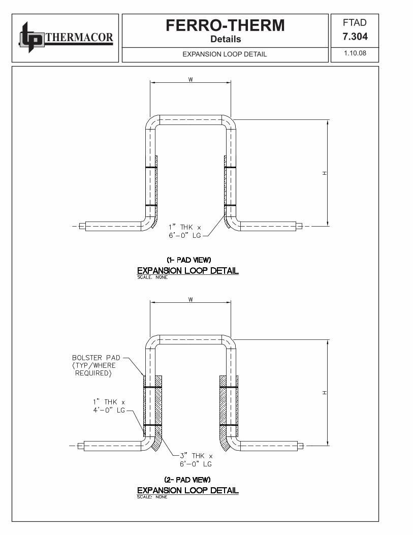
2.6 Expansion/ contraction compensation will be accomplished utilizing factory pre-fabricated and pre-insulated expansion elbows, Z-bends, expansion loops, and anchors specifically designed for the intended application. External expansion compensation utilizing flexible expansion pads (minimum one inch thickness), extending on either side, both inside and outside the radius of the fittings are used with all fittings having expansion in excess of 3/4”.
(Continued)
Specification Guide

THERMACORFERRO-THERM FTSG
7.1023.14.07STANDARD SPECIFICATION
Part 3 - Execution
3.1 Pre-fabricated systems shall be provided as SC (standard components) fittings and factory insulated straight pipe sections for field engineering per the contract drawings. (At the Engineer’s option, system can be pre-fabricated/pre-engineered.) 3.2 Underground systems shall be buried in a trench not less than two feet deeper than the top of the pipe and not less than eighteen inches wider than the combined O.D. of all piping systems. A minimum thickness of 24 inches of compacted backfill placed over the top of the pipe will meet H-20 highway loading. 3.3 Trench bottom shall have a minimum of 6” of sand, pea gravel, or specified backfill material as a cushion for the piping. All field cutting of the pipe shall be performed in accordance with the manufacturer’s installation instructions. 3.4 A hydrostatic pressure test of the carrier pipe shall be performed per the engineer’s specification with a factory recommendation of one and one-half times the normal system operating pressure for not less than two hours. Care shall be taken to insure all trapped air is removed from the system prior to the test. Appropriate safety precautions shall be taken to guard against possible injury to personnel in the event of a failure. 3.5 Field Service, if required, shall be provided by a certified manufacturer’s representative or company field ser-vice technician. The technician will be available at the job a minimum of one day (or more if required by job size) to check unloading, storing, and handling of pipe, pipe installation, pressure testing, field joint insulation, and backfilling techniques.
Specification Guide

THERMACORFERRO-THERM
Specification Guide
FTSG7.10310.07.11POLYURETHANE FOAM IN HDPE JACKET
Carrier Pipe: d > 2” - A53 ERW Grade B, Std. Wt. Black Steel d < 2” - A106 SML, Std. Wt. Black Steel - Seamless and Schedule 80 pipe available for all sizes - Std. Wt. is the same as Schedule 40 for all sizes thru 10” - XS is the same as Schedule 80 for all sizes thru” 8”
Jacketing Material: High Density Polyethylene (HDPE)
Insulation: Polyurethane Foam
D
L
d
t
* Other pipe sizes and pipe and jacket combinations are available.** Insulation thickness is calculated using minimum wall thickness. Actual wall thickness may be greater than stated, thereby minimally decreasing actual foam thickness.
PipeSize
JacketSize
StandardLength
L
InsulationThickness
t
WeightPer Foot
(lbs.)1/2” 5.4” 20’ 2.2” 1.93/4” 5.4” 20’ 2.1” 2.21” 5.4” 20’ 1.9” 3.2
1-1/4” 5.4” 20’ 1.8” 3.81-1/2” 5.4” 20’ 1.7” 4.2
2” 5.4” 40’ 1.4” 5.12-1/2” 6.7” 40’ 1.8” 7.7
3” † 5.7” 40’ 1.0” 9.16.7” 40’ 1.5” 9.5
4” † 6.7” 40’ 1.0” 12.5† 7.7” 40’ 1.5” 13.08.7” 40’ 2.0” 13.5
5” † 7.7” 40’ 1.0” 16.78.7” 40’ 1.5” 17.1
6” † 8.9” 40’ 1.0” 21.5† 9.9” 40’ 1.5” 22.010.9” 40’ 2.0” 22.4
8” † 10.9” 40’ 1.0” 31.5† 11.9” 40’ 1.5” 32.212.9” 40’ 2.0” 32.9
10” † 13.0” 40’ 1.0” 44.314.1” 40’ 1.6” 46.3
12” † 15.0” 40’ 1.0” 55.416.1” 40’ 1.6” 56.2
14” † 16.2” 40’ 1.0” 60.8† 17.2” 40’ 1.5” 61.918.2” 40’ 2.0” 63.0
PipeSize
JacketSize
StandardLength
L
InsulationThickness
t
WeightPer Foot
(lbs.)16” † 18.3” 40’ 1.0” 69.7
† 19.3” 40’ 1.5” 71.220.3” 40’ 2.0” 72.7
18” † 20.3 40’ 1.0” 79.6† 21.3” 40’ 1.5” 80.722.3” 40’ 2.0” 81.8
20” † 22.4” 40’ 1.0” 88.6† 23.4” 40’ 1.5” 87.824.4” 40’ 2.0” 90.9
24” † 26.3” 40’ 1.0” 106.3† 27.3” 40’ 1.5” 108.128.3” 40’ 2.0” 109.9
28” † 30.3” 40’ 1.0” 126.0† 31.3” 40’ 1.5” 127.532.3” 40’ 2.0” 129.0
30” † 32.3” 40’ 1.0” 140.0† 33.3” 40’ 1.5” 141.536.6” 40’ 3.2” 143.0
† Pipe/ Jacket combination available on sticks & kits only.

THERMACORFERRO-THERM
0
10
20
30
40
50
60
70
100 120 140 160 180 200 220 240 260
0
5
10
15
20
25
30
35
40
45
50
100 120 140 160 180 200 220 240 260
FTSG7.1043.14.07HEAT LOSS DIAGRAM (1” - 8” PIPE)
Specification Guide
1”
2”
3”
4”
6”
8”
1”
2”
3”
4”
6”
8”
HEAT LOSS FOR 2” OF POLYURETHANE FOAM*
HEAT LOSS FOR 1” OF POLYURETHANE FOAM*
Service Temperature (°F)
Service Temperature (°F)
Qloss
(Btu/ft/hr)
Qloss
(Btu/ft/hr)
- Burial depth: 36”- Soil conductivity: 12 (Btu/h.ft2.°F/ft)- Soil temperature: 50°F
- Burial depth: 36”- Soil conductivity: 12 (Btu/h.ft2.°F/ft)- Soil temperature: 50°F
* Values are calculated using 3E Plus in accordance with ASTM C680 and are subject to the terms and limitations stated in the software. Actual heat loss may vary.

THERMACORFERRO-THERM
0
20
40
60
80
100
120
140
100 120 140 160 180 200 220 240 260
0
20
40
60
80
100
120
140
100 120 140 160 180 200 220 240 260
FTSG7.1053.14.07HEAT LOSS DIAGRAM (10” - 30” PIPE)
Specification Guide
HEAT LOSS FOR 2” OF POLYURETHANE FOAM*
HEAT LOSS FOR 3” OF POLYURETHANE FOAM*
Qloss
(Btu/ft/hr)
Qloss
(Btu/ft/hr)
- Burial depth: 36”- Soil conductivity: 12 (Btu/h.ft2.°F/ft)- Soil temperature: 50°F
- Burial depth: 36”- Soil conductivity: 12 (Btu/h.ft2.°F/ft)- Soil temperature: 50°F
Service Temperature (°F)
Service Temperature (°F)
10”12”
16”
20”
24”
30”
18”
10”
12”
16”
20”
24”
30”
18”
* Values are calculated using 3E Plus in accordance with ASTM C680 and are subject to the terms and limitations stated in the software. Actual heat loss may vary.

THERMACORFERRO-THERM
Installation ManualFTIM7.2013.14.07GENERAL INSTALLATION INSTRUCTIONS
UNLOADING & HANDLINGLift joints from trucks. DO NOT DROP SHARP OR HEAVY OBJECTS ON INSULATED UNITS. DO NOT use chains or other devices which might puncture insulation jacket.
STORAGEPipe is stockpiled off the ground. Do not exceed a stacking height of 6’. Prevent dirt and debris from entering pipe. Fittings, joining materials, etc. must be stored indoors to protect them from freezing, overheating, moisture, or loss.
LAYING OF PIPE UNITS – TRENCHINGAll sharp rocks, roots, and other abrasive material must be removed from the trench. The trench bed should be 6” of sand or backfill as specified by the engineer, providing a smooth and uniform stabilizing surface (sandbags may be used as a means to keep the pipe off the ground until backfilling is started). The trench width should provide a mini-mum of 6” from trench wall to jacket O.D. and a minimum of 6” between pipe units. Trench depths will be indicated on the contract drawing and in line with good construction practices. Trench depth should allow for a minimum cover of 24” on top of the insulated unit.
FIELD JOINING METHODSFerro-Therm piping and fittings shall be joined in the field using approved methods of welding for appropriate pipe.
FIELD ALTERATIONSPipe will be cut in the field, based on the appropriate field measurements for fabrication of loops, fittings, and/ or mak-ing manhole or wall entries unless the system is pre-engineered with piece mark sections and/ or with pre-fabricated/ pre-insulated fittings. If special short pieces are required, measure distance needed for field alteration and cut through unit with saw. Using factory insulated pipe as guide, cut back insulation and bevel pipe (simultaneously removing burrs, cuts, nicks, and scratches). Apply end seal to the clean, dry, exposed insulation surface, if required.
HYDROSTATIC TESTINGAnchor blocks shall be poured and cured, prior to testing. Bleed all air from lines to eliminate possible incorrect read-ings. The hydrostatic pressure test shall be performed per the engineer’s specification with a factory recommendation of one and one-half times the normal operating pressure for not less than two hours. Inspect all fittings, valves, and couplings at this time. Appropriate safety precautions shall be taken to guard against possible injury to personnel in the event of a failure.
FIELD JOINT & FITTING INSULATIONSee Drawings furnished with job material.
BACKFILL FINALBefore backfilling is started, the trench should be cleaned of any trench wall cave-ins and general trash, especially metal. Backfilling should be done with sand or other engineer-approved material 6” below the casing to 1’ above. Engineer-approved backfill may be used to fill the rest of the trench. This material should be free of rocks, roots, large clods, or anything that could cause damage to the jacket. Jacket should have a minimum of 2’ cover.
WHEELED OR TRACKED VEHICLES SHALL NOT BE USED FOR TAMPING!
INSTALLATION INSTRUCTIONS

THERMACORFERRO-THERM
Installation ManualFTIM7.2023.14.07SHIPPING & HANDLING
SHIPPING & HANDLING INSTRUCTIONSHANDLE COATED PIPE WITH EXTRA CARE! THIS PIPE CAN DAMAGE WHEN HANDLED, MOVED, OR STORED IMPROPERLY!
UPON RECEIPT OF MATERIALSMake an overall inspection of the load, checking all bands and braces to see if they are intact. Also, check the load for shifting. If the load has shifted, or if the braces and bands are broken, examine each pipe for damage. HAVE THE TRUCK DRIVER MAKE AN ITEMIZED NOTATION OF ANY DAMAGE ON THE DELIVERY RECEIPT AND HAVE IT SIGNED BY THE DRIVER.
CHECK PACKING LISTCompare materials received with those listed on the packing list. Count all pipe and boxes. NOTE ANY SHORTAGES ON DRIVER’S DELIVERY RECEIPT.
CHECK BOXESOpen all boxes and inspect for damages, shortages, and correct size. REPORT ANY DISCREPANCIES WITHIN 30 DAYS AFTER RECEIPT.
CLAIMS FOR DAMAGESClaims for damages in transit or lost goods must be made within 30 days. The filing of any claim is the Purchaser’s Responsibility. Thermacor will file any claim on Purchaser’s behalf upon receipt of the following: 1. Written authority to file such a claim. 2. Written notice of loss or damage (signed and noted Bill of Lading) by truck driver or carrier freight agent.
UNLOADING PIPEPipe may be unloaded by hand or with fork lifts*, cherry pickers, or cranes. DO NOT HOOK pipe ends. Minimum 4” wide straps or slings should be used.
* Fork Lift – When using Fork Lift, wide tines or a large surface covering the fork tines must be used to prevent coating damage. Fork Lift must be able to handle the weight of the insulated pipe length.
PIPE STOCKPILINGPipe should be stored on level ground, elevated to be as dry as possible, and in such a way that the pipe ends do not lie in water or on the ground. To prevent deformation of the jacket and insulation due to the weight of the pipe, place a series of supports (3 for 20’ or 5 for 40’) of ample size generally constructed from 2” x 4”s under the pipe as shown below. Supports should increase in width as weight load increases so that the top supports of a fully loaded stockpile should be approximately 10” wide, gradually increasing to the bottom level, approximately 18” wide. Pipe can be pyramided (within reasonable and safe limits) approximately 6’ high after a properly braced or chocked base is formed. Pipe stored outside for long periods of time can be covered with blue mesh tarpaulin (plywood can also be used). Do not prevent airflow as jacket can be deformed from heat buildup.
NOTE: Thermacor does not approve of the practice of installing pipe and fittings, and backfilling the pipe before testing. Thermacor will not allow or pay claims for charges which arise in locating and digging up leaks regardless of cause.
BE VERY CAREFUL NOT TO DROP THE PIPE!
6'20'
6'20'
6'20'

THERMACORFERRO-THERM
PIPING RISER DETAILSCALE: NONE
ELEVATION
5'-0"
HDPE JACKET
PIPE SLEEVE & SEAL(BY INSTALLING CONTR.) 1'
-0"
FIN. FLR.
CARRIER PIPE
5'-0
" C-E
BLOCK (BY OTHERS)CONCRETE ANCHOR
5'-0
" C-E
BUILDING RISER DETAILSCALE: NONE
HDPE JACKET
WALL SLEEVE AND SEAL(BY INSTALLING CONTR.)
FOUNDATION
90° ELBOW
FLOOR SLEEVE AND SEAL(BY INSTALLING CONTR.)
FIN. FLR.GRADE
1'-0
"
CARRIER PIPE
ANCHORPLATE
EXTERIORWALL
5'-0"
BLOCK (BY OTHERS)CONCRETE ANCHOR
ELEVATION
ANCHOR BLOCK SHALL BE LOCATEDMINIMUM OF 3'-0" FROM WALL
FLOOR SLEEVE AND LINKSEAL(BY INSTALLING CONTRACTOR)
CARRIER PIPE
HDPE JACKET
INSULATION
GRADE
OUTSIDE FACEOF WALL
90° ELBOW
CARRIER PIPE
FIN. FLR.
ANCHOR PLATE
FLOOR SLEEVE AND LINKSEAL(BY INSTALLING CONTRACTOR)
OUTSIDE FACEOF WALL
HDPE JACKET
INSULATION
CARRIER PIPE
GRADE
ELEVATION
90° ELBOW
CARRIER PIPE
FIN. FLR.
BUILDING RISER DETAILSCALE: NONE
SCALE: NONEBUILDING RISER DETAIL
1'-0
"
5'-0
" 5'-0
"
1'-0
"
DetailsFTAD7.3013.14.07RISER DETAIL

THERMACORFERRO-THERM
WALL PENETRATION DETAIL
SITE PLAN DIMENSIONS END HERE
CARRIER
SCALE: NONE
HDPE JACKET
INSULATION
PIPE
WALL SLEEVE AND SEAL(BY INSTALLING CONTR.)
OUTSIDE FACE OF WALL
3"
9"
DetailsFTAD7.3023.14.07WALL PENETRATION DETAIL

THERMACORFERRO-THERM
DetailsFTAD7.3031.09.08EXPANSION BOLSTER DETAIL
THERMACORFERRO-THERM
DetailsFTAD7.3041.10.08EXPANSION LOOP DETAIL

THERMACORFERRO-THERM
DetailsFTAD7.3053.14.07 ANCHOR DETAIL

THERMACORFERRO-THERM
DetailsFTAD7.3063.14.074 PIPE TRENCH DETAIL
SCALE: NONE
HDPE JACKET (TYP)
GRADE
EARTH
TRENCHWALL
UNDISTURBED
MIN
IMU
M
A
4-PIPE TRENCH SECTION
MIN.6" B
6" SAND OR SELECT
BOTTOM OF TRENCHBACKFILL BED IN
TOP OF JACKET
SAND OR SELECTBACKFILL 6" OVER
24" MIN. OF SELECT BACKFILL
CARRIER PIPE (TYP)
TRENCH PIPING SCHEDULETRENCHSECTION DIMENSION
??A-A
C-C
D-D
B-B
?
?
?
?
?
?
DIMENSIONA B
?
?
?
?
DIMENSIONC
CMIN.
6"
MINIMUME
?
?
?
?
DIMENSIOND
?
?
?
DIMENSION
?
E
D