Embed Size (px)
Citation preview

Nuevas técnicas de automatización industrial
Festo CMMP-AS Configuration Manual
19 January 2022
www.nutai.com
© NUTAI S.L. 2021. All rights reserved

Overview
© NUTAI S.L. 2021. All rights reservedPage 2
1 Introduction
2 Necessary software
3 Connection with controller
4 Project creation
5 Component selection
6 Configuration
7 Support

Overview
© NUTAI S.L. 2021. All rights reservedPage 3
1 Introduction
2 Necessary software
3 Connection with controller
4 Project creation
5 Component selection
6 Configuration
7 Support

This manual explains the configuration of Festo CMMP-AS motor controller so that itcan be operated from a UR robot using the NUTAI URCap Multi Axis Drive (MAD)Controller.
Note that this manual explains the minimum required configuration, so it is leftpending for the user to complete other configuration options specific for their endapplication.
Introduction
© NUTAI S.L. 2021. All rights reservedPage 4

Overview
© NUTAI S.L. 2021. All rights reservedPage 5
1 Introduction
2 Necessary software
3 Connection with controller
4 Project creation
5 Component selection
6 Configuration
7 Support

Necessary software
To configure the Festo CMMP-AS motor controller, the Festo Configuration Tool (FCT)software —available for Windows— must be downloaded and installed on yourcomputer.
1 Festo oficial website:https://www.festo.com
To do this, go to the Festo1 website and download the latestversion available, making sure that it is compatible with yourCMMP-AS controller, as indicated in the following slides.
© NUTAI S.L. 2021. All rights reservedPage 6

Page 7
Necessary software

© NUTAI S.L. 2021. All rights reservedPage 8
Necessary software

Overview
© NUTAI S.L. 2021. All rights reservedPage 9
1 Introduction
2 Necessary software
3 Connection with controller
4 Project creation
5 Component selection
6 Configuration
7 Support

Connection with controller
Connect your Festo CMMP-AS controller to your computer —directly or through a switch—via Ethernet.
Ethernet [RJ-45]
© NUTAI S.L. 2021. All rights reservedPage 10
Overview
© NUTAI S.L. 2021. All rights reservedPage 11
1 Introduction
2 Necessary software
3 Connection with controller
4 Project creation
5 Component selection
6 Configuration
7 Support
Project creation
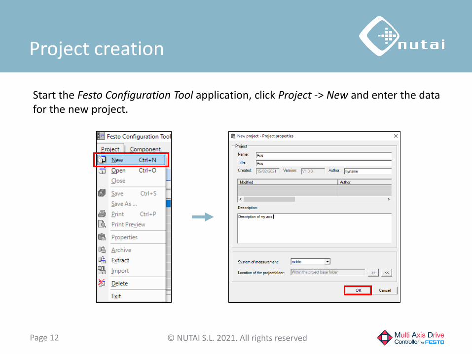
Start the Festo Configuration Tool application, click Project -> New and enter the data for the new project.
© NUTAI S.L. 2021. All rights reservedPage 12

Overview
© NUTAI S.L. 2021. All rights reservedPage 13
1 Introduction
2 Necessary software
3 Connection with controller
4 Project creation
5 Component selection
6 Configuration
7 Support

Component selection
Once the project is created, go to it, select the CMMP-AS component and enter a name for this component.
© NUTAI S.L. 2021. All rights reservedPage 14

The next step will be to create a new controller configuration. Click the Create new Drive Configuration button.
© NUTAI S.L. 2021. All rights reservedPage 15
Component selection

First, select the family and type of controller you have. If using DC power, enable the intermediate circuit option.
© NUTAI S.L. 2021. All rights reservedPage 16
Component selection

Then select the drive system: typically, Festo Motor with Axis.
© NUTAI S.L. 2021. All rights reservedPage 17
Component selection

The next step is to indicate the motor, the length of the cable and the reducer you have.
© NUTAI S.L. 2021. All rights reservedPage 18
Component selection

Now we select the type of axis we are going to use, typically a linear or rotative Festo axis (first 2 options).
© NUTAI S.L. 2021. All rights reservedPage 19
Component selection

Subsequently, we select the axis model that we will use.
© NUTAI S.L. 2021. All rights reservedPage 20
Component selection

Finally, the result of the selected configuration is displayed.
© NUTAI S.L. 2021. All rights reservedPage 21
Component selection

Overview
© NUTAI S.L. 2021. All rights reservedPage 22
1 Introduction
2 Necessary software
3 Connection with controller
4 Project creation
5 Component selection
6 Configuration
7 Support

Configuration
First, go to the Application Data category, click the Operating Mode Settings tab and select the control interface: Modbus/TCP. Also enable the Profile Position Mode and Homing Mode options.
© NUTAI S.L. 2021. All rights reservedPage 23

Configuration
© NUTAI S.L. 2021. All rights reservedPage 24
When modifying the control interface, a warning window may appear. Accept the reset of the affected pages by pressing the OK button.

Now click on the Environment tab and select the axis mounting position and the approximate total load.
© NUTAI S.L. 2021. All rights reservedPage 25
Configuration

We now access the Axis category and configure the limit and reference switches according to whether they are NC (Normally Closed) or NO (Normally Open). In case of not using them, we configure them as NO.
© NUTAI S.L. 2021. All rights reservedPage 26
Configuration

© NUTAI S.L. 2021. All rights reservedPage 27
Configuration
We access the Fieldbus subcategory and select the Operation Parameters tab. We verify that the Packet Segmentation1 option is disabled.
1 If this option is not visible, update the FCT CMMP plugin to a newer version.

We now select the Factor Group tab. We set the units we want to use —typically mm/in for linear axis and r/° for rotative axis— and configure the position, velocity and acceleration exponents to 10-2, as indicated in the image:
© NUTAI S.L. 2021. All rights reservedPage 28
Configuration
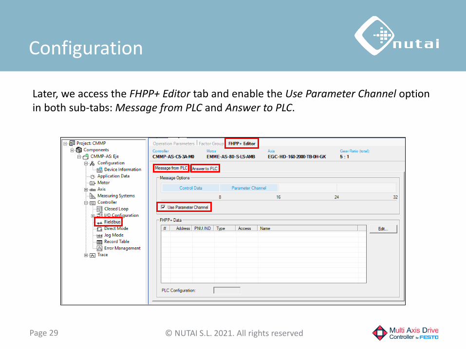
Later, we access the FHPP+ Editor tab and enable the Use Parameter Channel option in both sub-tabs: Message from PLC and Answer to PLC.
© NUTAI S.L. 2021. All rights reservedPage 29
Configuration

© NUTAI S.L. 2021. All rights reservedPage 30
Configuration
Finally, we select the Direct Mode tab and verify that the Smoothing1 parameter is set to a value of 0%.
1 Setting a percentage other than 0% can cause operational problems.
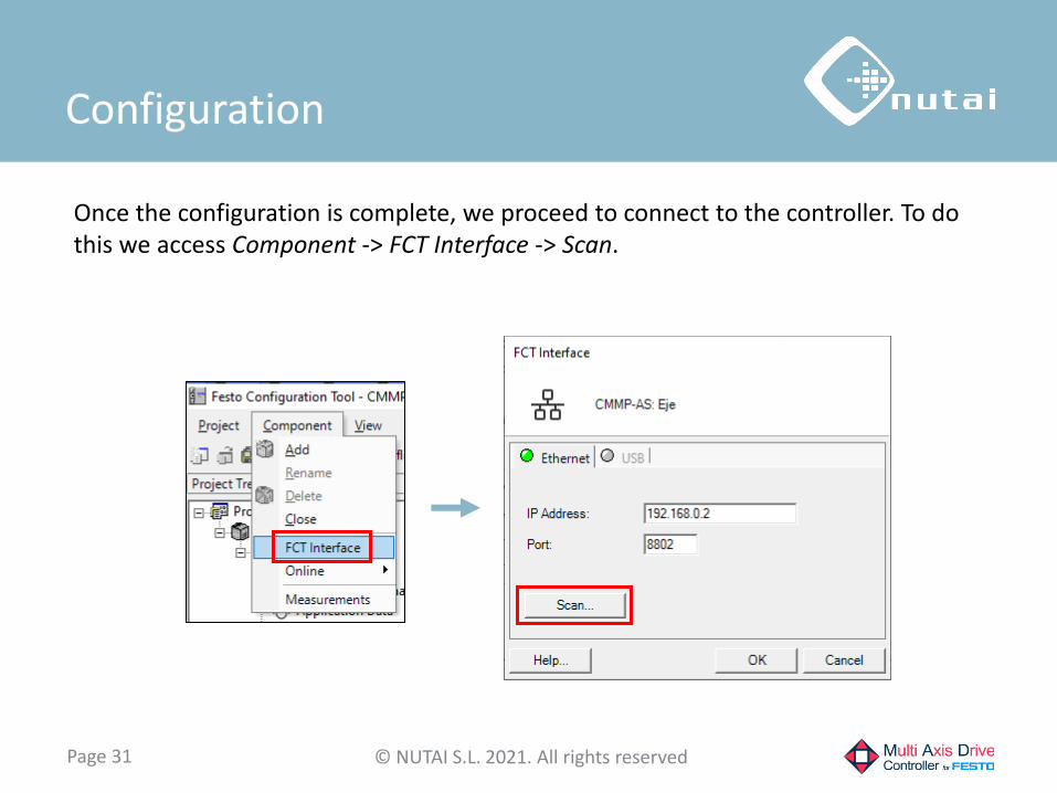
Once the configuration is complete, we proceed to connect to the controller. To do this we access Component -> FCT Interface -> Scan.
© NUTAI S.L. 2021. All rights reservedPage 31
Configuration

From this window we can see the devices found and their main data. It is also possible to modify1 its name and network configuration by right clicking on it and accessing the Network option.
1 You need to restart the controller to apply the changes.
© NUTAI S.L. 2021. All rights reservedPage 32
Configuration

Once the controller's IP address is known, we configure it in Component -> FCT Interface.
© NUTAI S.L. 2021. All rights reservedPage 33
Configuration

Now we proceed to connect to the controller by clicking on the connection icon. A warning message will be displayed, and we will click the Download button to download the project data to the controller.
© NUTAI S.L. 2021. All rights reservedPage 34
Configuration

© NUTAI S.L. 2021. All rights reservedPage 35
Configuration
Once the project is downloaded, we perform a Store in the controller to permanently save the changes in its non-volatile memory.

© NUTAI S.L. 2021. All rights reservedPage 36
Configuration
IMPORTANT: make sure your motor controller has firmware version 4.0.1501.2.411 or later installed to avoid any incompatibility.
1 In case you have an older version installed, get the latest version from the Festo website and download it to your controller from Component -> Online -> Firmware Download.

Finally, it is a good idea to check that the downloaded configuration works correctly.
To do this, we access the Manual Move tab and enable the FCT and Enable options to enable the controller. Subsequently, we jog the axis to one side —for example, 60 mm— and physically measure the displacement to confirm that it is correct.
© NUTAI S.L. 2021. All rights reservedPage 37
Configuration

Overview
© NUTAI S.L. 2021. All rights reservedPage 38
1 Introduction
2 Necessary software
3 Connection with controller
4 Project creation
5 Component selection
6 Configuration
7 Support

For further information, please contact:
NUTAI S.L.
Pol. Ind. L´Alteró, Av. del Palmar, 946460 Silla (Valencia)
Spain
Phone: +34 961 76 70 85Email: [email protected]
www.nutai.com
Support
© NUTAI S.L. 2021. All rights reservedPage 39


![EtherCAT for motor controllers CMMP−AS · Description EtherCAT CMMP−AS Description 570 924 en 0912NH [749 128] EtherCAT for motor controllers CMMP−AS](https://img.pdfslide.net/doc/110x75/5aedbf437f8b9a45569014dd/ethercat-for-motor-controllers-cmmpas-ethercat-cmmpas-description-570-924.jpg)