Embed Size (px)
Citation preview

G.Magazzù - INFN Pisa 1
FF-LYNX (*): Fast and Flexible protocols and interfaces for data transmission and distribution of
clock, trigger and control signals
(*) project funded by the INFN 5th Commission
R. Castaldi, G. Magazzù, P. G. VerdiniR. Castaldi, G. Magazzù, P. G. VerdiniINFN – Sezione di PisaINFN – Sezione di Pisa
G.G. Bianchi, Bianchi, L. FanucciL. Fanucci, S. Saponara, C. Tongiani, S. Saponara, C. TongianiDipartimento di Ingegneria della Informazione (DII-EIT) - Università di PisaDipartimento di Ingegneria della Informazione (DII-EIT) - Università di Pisa
G.Magazzù - INFN Pisa 2
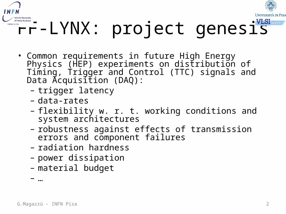
FF-LYNX: project genesis• Common requirements in future High Energy Physics (HEP)
experiments on distribution of Timing, Trigger and Control (TTC) signals and Data Acquisition (DAQ): – trigger latency– data-rates – flexibility w. r. t. working conditions and system
architectures– robustness against effects of transmission errors and
component failures– radiation hardness– power dissipation– material budget– …

G.Magazzù - INFN Pisa 3
FF-LYNX: project goals
• Definition of a “standard” and “flexible” protocol for the integrated distribution of TTC signals and DAQ
• Development of functional simulators to validate the protocol and evaluate the overall system performance under different hypotheses on sensor geometry, detector architecture and working conditions (inputs from HEP communities)
• Implementation of the protocol in custom low power and radiation tolerant digital interfaces designed and produced in a commercial CMOS technology (≤130nm)
• Test and characterization (including irradiation tests) of the interface prototypes and development of a library of IP-Cores accessible to designers of ICs for the future experiments
G.Magazzù - INFN Pisa 4
FF-LYNX: key features• Integrated distribution of TTC signals and DAQ:
– transmission of TTC and DAQ data handled by the same protocol and the same hardware components
– no more Trigger encoded with missing clock pulses – no more “slow control” protocols or “custom” fast control protocols
• Robustness of critical data w.r.t. transmission errors • “General purpose” structure of data frames (i.e.: transparent w.r.t. data
types)• Easy coupling of FF-LYNX interfaces with “host” ASIC cores (serial and
parallel ports)• Flexibility with respect to system architecture (e.g.: Point-To-Point, Ring)• Supporting different (standard or custom) link technologies (e.g.: LVDS)• Supporting different link speeds: 160 or 320 Mbps in the Down-Link
(toward the detector) and 80, 160, 320 or 640 Mbps in the Up-Link (from the detector)

G.Magazzù - INFN Pisa 5
FF-LYNX: TTC & DAQTriggers, Headers and Sync commands and data frames share the same link • 4 or 8 bits transmitted in each 40MHz clock cycle (160 or 320 Mbps)• 2 bits for Trigger, Headers and Sync commands (THS), 2/6 bits for frames (FRM)• Triggers transmitted with the highest priority (constant latency)

G.Magazzù - INFN Pisa 6
FF-LYNX: frame structureFrame structure transparent with respect to payload • Header (HDR): “error robust” 6-bit encoding• Frame Length and Type (FLT): Hamming 4/8 encoding (number of 16-bit words – 0
to 7, Label On/Off) • Label: 16-bit label associated to the payload (e.g.: time stamp for raw data that
can be used in data concentrators with event building capabilities to merge data associated to the same trigger and generated by different Front-End ASICs)
• Payload: commands, raw data (e.g.: hit data associated to triggers), trigger data (subset of hit data – e.g.: coordinate of strip clusters – that could be used in trigger generation), configuration and monitoring data (e.g.: current values of configuration registers)
• CRC: optional CRC on the payload
Possible frame payload: 3 byte I2C command
G.Magazzù - INFN Pisa 7
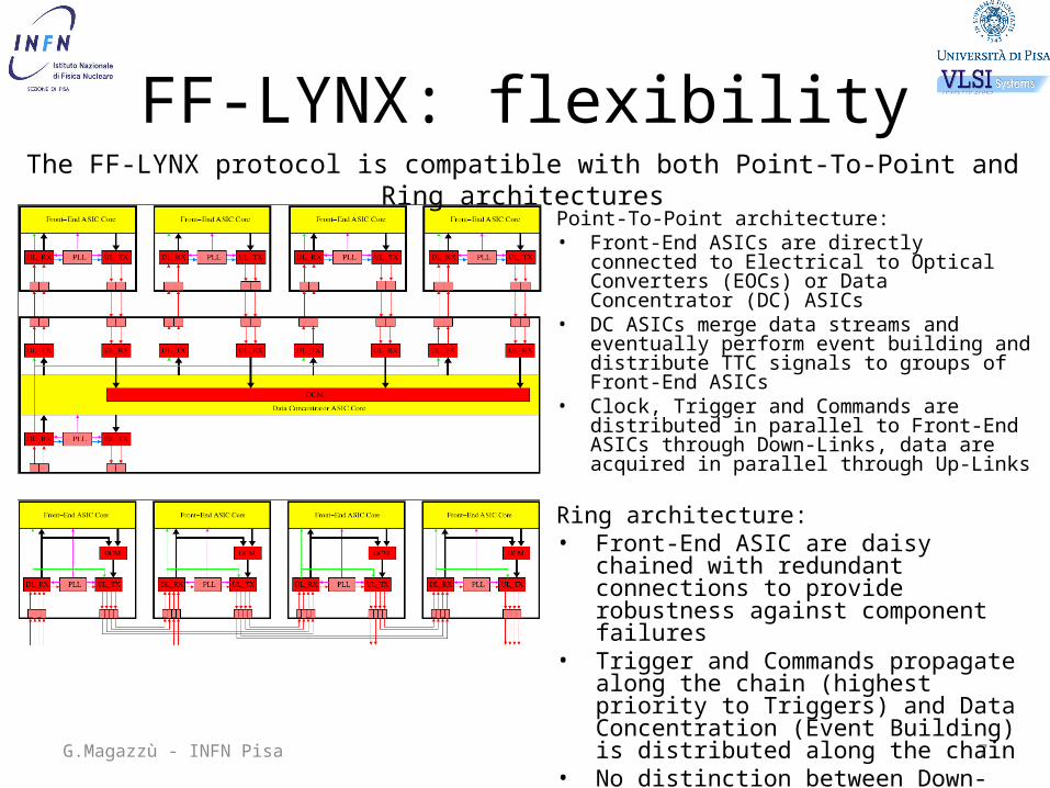
FF-LYNX: flexibility
Point-To-Point architecture: • Front-End ASICs are directly connected to
Electrical to Optical Converters (EOCs) or Data Concentrator (DC) ASICs
• DC ASICs merge data streams and eventually perform event building and distribute TTC signals to groups of Front-End ASICs
• Clock, Trigger and Commands are distributed in parallel to Front-End ASICs through Down-Links, data are acquired in parallel through Up-Links
Ring architecture:• Front-End ASIC are daisy chained with
redundant connections to provide robustness against component failures
• Trigger and Commands propagate along the chain (highest priority to Triggers) and Data Concentration (Event Building) is distributed along the chain
• No distinction between Down-Links and Up-Links
The FF-LYNX protocol is compatible with both Point-To-Point and Ring architectures
G.Magazzù - INFN Pisa 8
FF-LYNX: applications (1/4)
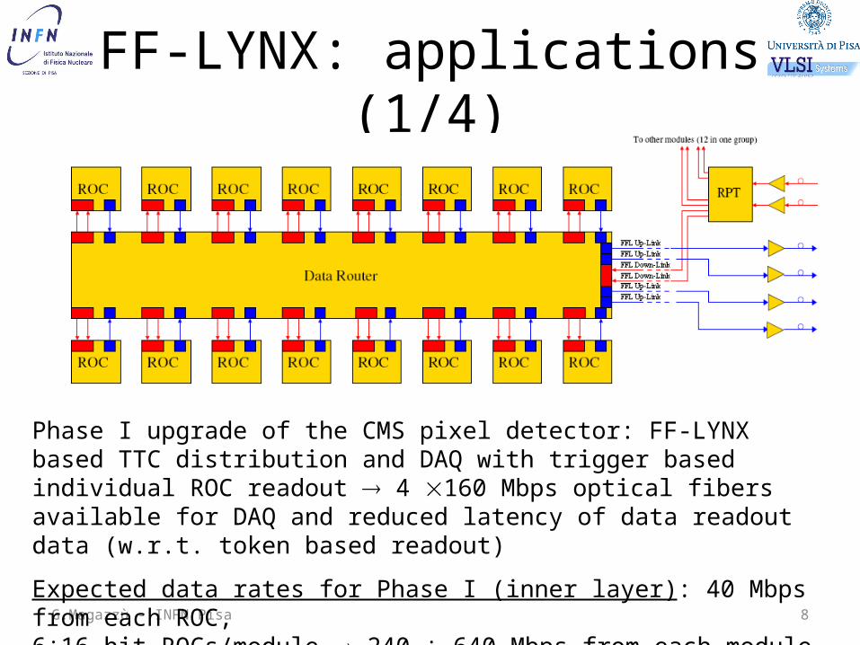
Phase I upgrade of the CMS pixel detector: FF-LYNX based TTC distribution and DAQ with trigger based individual ROC readout 4 160 Mbps optical fibers available for DAQ and reduced latency of data readout data (w.r.t. token based readout)
Expected data rates for Phase I (inner layer): 40 Mbps from each ROC, 6÷16 hit ROCs/module 240 ÷ 640 Mbps from each module (16 ROCs).

G.Magazzù - INFN Pisa 9
FF-LYNX: applications (2/4)
Phase II upgrade of the CMS pixel detector: two 640 Mbps electrical links from each ROC; two uplink optical fiber (≥ 1.6 Gbps) for each 4-ROC module and one downlink optical fiber optionally shared among several modules.
Expected data rates for Phase II (inner layer): 800 Mbps from each ROC, up to 3.2 Gbps from each module (4 ROCs).

G.Magazzù - INFN Pisa 10
FF-LYNX: applications (3/4)
Phase II upgrade of the CMS Strip Tracker (no trigger data readout): daisy chains of Front-End ASICs within the modules and, optionally, daisy chain of modules. Expected data rate for raw data, at r = 78 cm: 5 Mbps/FE chip 40 Mbps/module.

G.Magazzù - INFN Pisa 11
FF-LYNX: applications (4/4)
Phase II upgrade of the CMS Strip Tracker (trigger data readout and embedded trigger processors): data concentrators in the modules and high speed links between modules and trigger processors.Expected data rate for trigger data, at r = 78 cm: 120 Mbps/FE chip 960 Mbps/module.

G.Magazzù - INFN Pisa 12
FF-LYNX: current status• Preliminary phase of the analysis of the system requirements
completed• First version of a test bench for functional simulations (based on
the current control and readout system of the CMS pixel detector) completed and operational
• Preliminary protocol and interface architecture (based on inputs so far received from CMS and Atlas) drafted and open to further refinements
• First VHDL models of the building blocks of the interfaces (synchronization block, trigger scheduler) developed and validated
• Analysis of different solutions to increase robustness against SEEs (triple redundancy, “SEU robust” encoding of FSM states, use of “ghost” registers) ongoing
• Tentative architecture of the test circuit TC1 defined• Technology (e.g.: I/O libraries and PLL for TC1) survey under way
G.Magazzù - INFN Pisa 13
FF-LYNX: short term plans• The proposal for a CMS R&D activity (F3-LYNX) will be
submitted soon: the draft of the proposal is currently reviewed by the members of the collaboration (extended w.r.t. FF-LYNX – UCSB, …)
• Physicists involved in physics simulations based on new detector architectures (UCSB) and in the design of future Front-End ASICs (PSI, IC) will provide guidelines for improving the protocol, the interface architecture and the system simulators
• The development of a “proof of concept” FPGA based prototype and relative “test bed” will be completed in summer 2009
• The design of the test circuit TC1 will be completed: the submission is foreseen in fall 2009
G.Magazzù - INFN Pisa 14
AcknowledgmentsThanks for fruitful discussions and support to:• R. Horisberger, H. C. Kaestli (PSI)• G. Hall, M. Raymond (IC)• J. Incandela (UCSB)• R. Beccherle (INFN-GE)• F. Palla, A. Messineo (INFN-PI)
We appreciate comments and suggestions from … potential FF-LYNX users:
[email protected]@iet.unipi.it