Embed Size (px)
Citation preview
fffOCAR, lC

ProCart II ™
MOBILE TREATMENT CONSOLE
OPERATIONS MANUAL
© 1998, DNfLworks EqUipment Corporation, All Rights Reserved
DNTL\\~L.---r __ .... --!--~ . .L ~-,oration
15 DNTLworksTld Equipment Corp. It B Engl 7300 South Tucson Way i USA
Centennial., CO 80112 USA (303) 693-1410
FAX (303) 693-6189 1(800) 847-0694
4/96 proman.doc

TABLE OF CONTENTS
I. Introduction 3
II. Customer Service 3
III. Umited Warranty 3-4
IV. Description of Your ProCarl II TV & Features 4-5
V. Specifications 5
VI. Views 6-8
Vll .. Setup Inshuctions 9
VIII. Operation 9-11
IX. Shut Down Instructions 11
X. CDC Infection Control Guidelines 11-13
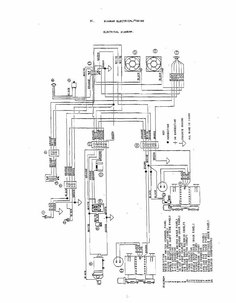
Xl. Diagrams Bechical/Tubing 14+
2

I. INTRODUCTION
DNTlxvorks Equipment Corp:Jration thanks you for the purchase of this ProCart IT"'" Mobile T reabnent Unit. The inf~:mnation contained in this manua.I should answer any questions regarding setvice and operation of your system.
All authorized personnel who operate, mainiain or service this ProCarl II'TW system should carefully review this manual before attempting to o~rate, ~rforrn maintenance, or selViC2 your ProCart IPlt. The system should be operated and maintained by trained parsonnel only. Should any question or problem arise, contact our Customer Service Deparlment at the nwn~rs listed below.
Although your ProCart II'TW has been designed and tested for maximum safety and optimum pe:nonnance, it is sold with the express understanding that DN'fLUJOrks, its subsidiaries, agents and representatives will not accept any resp:msibility for:
1) Operator's lack of knowledge, negligence or carelessness in the o-peration of this equipment. 2) Equipment not properly maintained or serviced. . 3) Injury to r:ersonnel or patienis from impro}!er use. 4) MooHication or tampering of any kind.
II. CUSTOMER SERVICE
In the event you require assisiance with your ProCarlIITw, please call (800) 847-0694 or (303) 693-1410 andspaak with one of our customer service representatives. Our service hours are from 8:00 a.m. to 5:00 p.m., in the Mountain Time lDne (USA), Monday through Friday, excluding hoUdays.
In most instanoos t service problems can be salved over the telephone. If more detailed selVice is required, a service technician in your a~ may be located or you may ship the unit to our factory for repair.
Warranty selVice will be perlonned in accordance with DNfLworks Equipment Coq:::oration's IJmited Warranty. Non~nanty service will be provided at reasonable p.:'.\rls and labor ccsis.
III.. The DNI1.works EQUIPMENT CORPORATION LIMITED WARRANlY
DN1L\VOrks Equipment Corp:>ration (ItDNfLUJOrks") warrants to purchaser that these produds are free from defecfs in materials and/or VJOrkmanship for three (3) full year from date of delivery. In addition, DNILVJOrks extends a ninety (90) day labor warranty from the date of delivery for all products we offer. Shipping charges to the factory under . warranty shall be the resp::;nsibility of the customer. DNTLworks will bear the cost of shipping the product(s) back to the customer.
During the warranty period, all pans which, up::ln inspection and examination by DNIl.works are proven to be defective, will be replaced free of charge. All decisions concerning whether a part will be repaired or replaced and the marmer, methoo, and extent of such repair or replacement sha11 be at the sole discrefion of DNTLworks.
The resp:msibillty of DNTLworks does not indude repair and replacement costs resulting from misuse, abuse, impro~r maintenance, or nonnal \\lear and tear. DNILworks will pay labor costs for warranty service for a }:erlod of 90 days from the date of purchase. DNILv.x:>rksl sole obllgafion under said \lJarranty is to repair, or, at its option, replace the defective part. The buyer shall have no options. The warranty shall be voided by alterations of equipment except those made by DNTI.JNOrKs, or tampering, improper installation or maintenance, accident or mocIification. This warranty expressly excludes all damage to the prcxiucts resulting from careless or neglectful transportation.
3

DNI1..works shall in no event be resp::msible for any work done without first obtaining DNrLworks' consent.
TIlls warranty is made expressly in lieu of all other warranties, expressed or impliecL inclurung any implied warranties of merchan1ability or fitness for a parlicular purpose. No employee, agent, franchise, dealer or other person is authorized to give any warranties of any nature on behalf of DNIlwork5. Except as provided herein, DNI1..works shall have no nability or resJX)nsibility to the customer or any other p21SOn or entity with TeSf:ect to any liability, loss or damage caused or alleged to be caused directly or indirectly by equipment soIcL leased, or furnished by DNIl.works, including, but not limited to, any interruption of servi~, loss of business or anticipatory profits or consequential damages arising out of or connected with the sale, lease, use or anticip:1ted use of equipment. Notwithstanding the above limitations and warranties, DNTLworks' llabillty hereunder for damages incurred by customer or other shall not exceed the amount paid by customer for p:1rticWar equipment involved.
IV. DESCRIPTION OF YOUR PROCART IITM:
Your ProCarl llTW is an easy-to-dean, self-contained opera tory system that seis up in a just a few minutes. It requires no plumbing and is mobile for ease of movement between operatories or storage.
Caution: The l.axge b~ack ai.r pressuxe contro~ knob is factory set.
Air System: AdjustiIlg this knob may void the rna:nufa.ct:u.rers warranty
The internal air compressor will activate when the main lX'wer switch is turned on, mUng the air tank and pressurizing the water reservoir. The motor will automatically deactivate when air pressure reaches a certain factory-set leveL When air pressure drop; below said level, the compressor will automatically cyde again. To ensure maximtm1 .efficiency, a delay timer alloVJ5 the compressor to operate a full torque before compressing air. As p:1rt of end-of-theday maintenance, excess air and moisture may:be purged from the air tank by means of a push-button at the rear of the unit. See Page 10 for a more detailed explanation of purging the air tank
Removing a handpiece from iis automatic hanger and depressing the foot control will cause the handpiece to o~rate. Only one handpiece may be moo at a time. Tum the corresp:>nding hi-block adjustment screw to adjust handpiece ai pressure. H the air pressure is to:J low after full adjustment of the bi-block screw, you may tum the black main unit pressure regulator until the desired air pressure is reached. Set the handpiece pressures to the manufacturer's specifications.
The airAvater syringe may be used any time after the main PJwer switch is activated. Depressing the appropriate butlon{s} will result in air only, water only, or spray. Air and water flow to the handpiece is not adjusiable.
, -
There are tVJO quick-connects at the rear of the unit for air (air) and water (blue). You may use these connections to operate other equipment that require air or water, or you may connect the system to external air and water sources.
'Water System: The water reservoir should be filled about 3/4 full and monitored between pafienis. At the end of the day, you should empty the reselVoir, wipe it dry, and purge remaining water from the system.
Water coolant flow may be con1rolled tVJO ways: The toggle valve on the foot confrol will tum water on and off to all handpieces; or individual needle valve adjustment at the front of the unit will mnrro! water flow to each of the handpieces. If the handpiece does not require water, the needle valve should be dosed at all times. When using an external water source, you must disconnect the internal water container. H the external water source is above lCXJr:si, you must regulate this water source to lOOpsi or less.
Vacuum System: The internal vacuum pump is activated by a toggle switch kxated at the front of unit. You rna use either valve (sallva ejector or HVE) as needed. Ruids and other oral debris will fXlSS through a solids collector an
4

then to a sealed waste container. A vacuum relief vaJve inside the waste container conirols the negative pressure. A float system inside the waste container will stop vacuum flow when it is full, preventing spillage.
A Uquid waste pump is used to drain liquid waste from the waste container. It is activated by a toggle located on the control panel of the unit. It is highly suggested that waste be purged into a CDC-recommended clisposal receptacle or drainage system. You may also connect the unit to a J:.€rmanent waste system. Contact a plumber for installation and local code requirements.
Electrical System: Your ProCart UN is equipped with an internal duplex outlet. An external duplex outlet is also included and is located at the rear of the unit. The inside outlets may be used for handpiece fiber optic systems (optional) or any item that can be installed internally. The ouiside outlets may be used for any accessories that require electrical}:OWer. The electrical system is protected by a IS-Amp circuit breaker. The unit itself uses 7 amps or 840 watis. Accessories, or a combination of accessories, should not exceed 5 amps or 6(X) watts. Under UL544 "Medical and Denial Equipment" requirements, only 80% of the J:X)wer rated for a 15 amp circuit breaker may be used (12 ampi or 1440 watts).
Features: 1) Internal, oil-free compressor 2) Internal, oil-free vacuum pump 3) Intemalllquid waste purge pump 4) Internal air tank 5) Internal water container 6) Internal waste container and solids trap 7) Three-handpiece {or sonic air scaler} ready 8) Nr/Water syringe 9} Dual hose vacuum with autoclavable HVE and Saliva Ejector valves 10) Repair Kit
v. SPECIFICATIONS Dimensions: Length:
Width: Adjustable Height:
Total Weight: Eectrical: Voltage:
Frequency: Wattage:
Compressor: Hot'Se}X)wer: Working Pressure: AowRate: N..rTank:
Vacuum Pwnp: Horsepower. Vacuum Adjustment
Unit Sound:
Row: Container. Full Load:
20" (51 em) 21" (53 em) 30" (76 em) to 34" (86 em) 100 Lbs. (45.5~)
115Vac or 220Vac 60 or SO Hz 840WUnit 1440 Toial 1/3HP 7Gto l~i 2.Scfrn @ 40psi 4llter (1 gallon) 1/3HP 0'1 to 21"Hg 4.6dm 41iter (1 gallon) 4&)B@31
5

VI. COMPONENT 1A your VIEWS
Front View
Rgure# 1 2 3 4 5 6 7 8 9 10 11 12
3
2
8
9
Description Handpiece Holder # 1 Handpiece Holder #2 Handpiece Holder #3 HVE Valve Holder Saliva Ejector Holder Syringe Holder Water Row Adjusbnent Handpiece #1 Water Row .Adjusbnent Handpiece #2 Water Row Adjustment Handpiece #3 Vacuum Toggle Switch (ON'OFF) Foot Confrol Water Toggle (ON/OFF) Foot Control
6

Top View
Figure # 1 2 3 4 5 6 7 8 9 10 11 12 13
<:I 0 0
a 0 a
® 7
a 0
6
2
3
Description Handpiece #1 Air Pressure Adjustment Handpiece #2 Air Pressure Adjustment Handpiece #3 Air Pressure Adjustment Handpiece Pressure Ga~ge Air Regulator Water Container Wat2r Container Pressure Relief Valve Quick Conned PJr, Water Container (Red) Water Regulator
a
0
o· g
Quick Connect Water, Water Container (Blue) Waska Pump Power Switch (ON/OFF) Solids Trap Vacuwn Relief Valve
7
1 3
1 :I
11
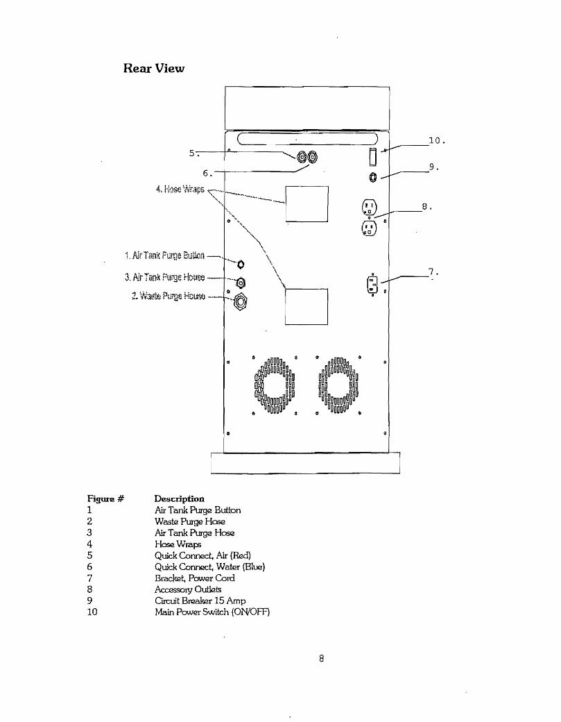
Rear View
Figure # 1 2 3 4 5 6 7 8 9 10
l (
5 -. ---t-''''------.....
6. --+-~---"'"
\. \ \0
D
Description Air Tank Purge Button Waste Purge Hose Air Tank Purge Hose Hose Wrap; Quick Connec~ Air (Red) Quick Connec~ Water (Blue) Brack2t, Power Cord ~ryOutlels ClICuit Breaker 15 Amp Main Power Switch (ON/OFF)
8
10. -----9 . ---
t...--__ 8 .
.._--7.

VII. SETUP INSTRUCTIONS
Plug In Power Cord: The PJwer cord must be connected to a 20 A1vIP }:Ower circuit with an earth ground. Never remov~ the ground from the JXM1€r cord plug. Attach the female end into the JX>wer receptacle on the back of the unit.
Fill Water Reservoir: Deactivate the unit Remove the quick connects from the control paneL Purge excess air ~ure from the TeseIVoir by depressing the red button on the lid. Unscrew and remove the lid. Fill the reservoir about 3/4 full to facilitate reinsiallation of the Ud. Replace the lld and reconnect the quick connects to the control J:etnel: (red tubing to quick connect with red washer, blue tubing to quick connect with blue washer).
Activating the Unit: Make sure that the vacuum and waste pump }:Ower switches are off before activating the main power switch.
Installing Your Handpieces: Install the handpieces to the appropriate siation. PleaseJnote that since the unit alloVJS individual air and water control to each station, there is no specific order in which handpieces are installed.
Check Handpiece Air Pressure: Check only one handpiece at a time. Remove a handpiece from its holder and depress the foot coniro] to full operating pressure. To adjl.lSt air pres5t.rre, tum the corresponding air adjl.lS"bnent screw on the control panel. H the air adjusrrnent screw is fully oJ:en and pressure is too low, then increase main air regulator pres51Jr2 tmtil the recommended pressure is reached. Repeat for each handpiece, as air pressure may differ for each one.
Check Water Row: Check only one handpiece at ~ time. Activate toggle on the foot control to "water on'! {red dot}. Remove a handpiece from its holder and depress the foot conirol. To regulate the water flow, adjust the corresponding needle valve at the front of the tmit Repeat for each handpiece. If a handpiece does not require water, c1cse the needle yalve completely.
Check AirJWater Syringe: Remover the syringe from Us holder. Depress the air butlnn and check that air floVJS at a consiant rate. Next, depress the water button and check the water flow. Depress the air and water buttons together to check for spray.
Check Vacuum System: Nfake sure that the lid on the solids trap is secure. Activate the vacuum PJwer switch. Check vacuum flow to both the HVE and saliva ejector valves. When checking on~ valve, make sure the other valve is closed. You can adjust the negative pressure by turning vacuum relief valve located on the conirol panel. Adjustment will not affect impede the vacuum flow.
VIII.. OPERATION
Handpieces: Handpieces should be changed or disinfected between each patient (see the CDC Infection Conirol Guidelines). -Handpiece pressure should be checked before each procedure .. You can adjust handpiece air pressure . with the foot control fully depressed and by adjusting the corresponding air prnssure adjustment screw on the confrol panel. Water coolant is activated by the toggle on the foot control. When toggle 15 off, no water coolant will flow to any handpiece. When foot ronirol toggle is on, water will flow through the handpiece that is removed from its holder. The water flow is conirolled by the coJTeS{X)nding needle valve on the front of the unit. Coolant air is not provided for any of the handpieces. Only one handpiece may be used at a time.
AirJ\Vaier Syringe: The three-way syringe may be used while a handpiece or the vacuum system is op2rating. The tip should be replaced or disinfected between each }X1tient (see CDC lrifection Control Guidelines). Disposable syringe tips may be used on the syringe.
9

Vacuum System: The vacuwn system consists of a saliva ejector, HVE (I-llgh Volwne Evacuator) valve, solids irap, UJaSte container, and liquid VJaSte pump_ Either the saliva ejector or the HVE valve may be used to achieve maximum p2rforrnimce. When using either valve: the other valve should be closed The solids trap screen should be cleaned or replaced between each patient. The waste container should be also drained regularly. A drainage tube and connector are supplied to purge fue waste from the internal container. Conned the tube to the waste pump port on the back of unit. Atmch or hold the end of the tube into a suitable disp::sal receptade and tum on the waste pump p::>wer swItch-lcx::ated-'On··the'conool--p:meL---·Never··leavewastepump.on.afierthe rontaineris,draine.dasJhiswill.sbori:en th~ life of the pLUTIp. The waste pump tubing can be permanently connected to a drain line. Contact a plumber in your area for assistance. The vacuum system should be cleaned between each patient (see CDC Infection Control Guidelines).
Water System: 'The water container should be checked or filled between each patient. To fill the water container, deactivate the unit. Next, dlsconneci the quick cormed with the red tubing. Depress the red pressure relief valve on the lld of the water container until all pressure is' re~oved from the container_ ,Disconnect the quick connect willi the blue tubing. Remove the lid and flU the container 3/4 full and replace lid. Reinstall fue quick connect with blue tubing firs~ and then the one with red tubing. The water system is equipped with a water regulator located on the control paneL H you require more water flow for either the handpieces or the syringe, you can increase the water regulator setting.
Caution: The ~arge b~ack air pressu:re con-tro~ knob is :fa.ctory set.
Air System: Adjusting this knob may void the manu.r,acrurexs waxxant;y
The air regulator has its own filter system that should be inspected periOOically. The regulator filter bowl may be drained by pressing the valve on the bottom of the bowl. Ar:cess to the bowl is gained through the water reselVoir opening in the control JXlneL Air pressure is controlled by a pressure, switch, which will cyde between 70 and 100 p3i. Refer the diagram on Page 8 and follow these instructions to purge excess air and moisture from the internal air tank as part of your daily end-of-the-day maintenance regimen.
1. Deactivate your ProCart ll. Place the end of the Air Tank Purge Hose (3) into a small container. 2. Depress the Air Tank Purge Button (1) for several seconds. Clean air and moisture from the air tank
only wiU be released through the Air Tank Purge Hose (3). There is no contact between the air tank' purge system and llie waste purge system. Refer to Vacuum System above for instructions on purging waste.
3. When completed release the Air Tank Purge Button (1), secure the Air Tank Purge Hose (3) around the Hose Wraps (4). Repeat this process at the end of each working day to ensure years of trouble~free . performance. Call Customer Service with any questions about this procedure.
Handpiece Flush: Handpiece flushing should be done after each patient. Remove all handpieces (that use water , coolant) from their holders. Hold the handpieces over a container and open all of the water flow needle valves. Activate the 'Water on" toggle and depress the foot control. Allow water to run 20 to 30 seconds. Replace the handpieces into their holds and refill the water container.
Accessory Quick-Connects: The accessory quick connects are located on the rear of unit (red for air and blue fo~ water). The red quick-connect is unreguJated, and win vary in pressure from 70 to 100 p;i. The blue quick-ronnect is regulated to the air regulator pressure on the control panel. It is usUally set at the highest handpiece pressure. ~ quick-connects may also be attached to in-office air and water supplies. An aa:essory air supply should not exceed 150 ~i, and water should not exceed 100 psi.
Cleaning: Cleaning should be done after each patient and at the end of each clay (see CDC Infection Conirol
Guidelines).
10

• DANGER: RISK OF EXPLOSION IF USED NEAR FlAMl\1ABLE ANESfHEllCS • WARNING: NEVER PLUG IN ANY COMBINATION OF ITEMS rnATWlLL USE MORE 11-IAN 5 AMPS. • CArmON HOTI AllOW UNIT TO COOL BEFORE SERVICING. • CAUI10N: TO REDUCE mE ruSK OF ELECTRICAL SHOCK, DO NOT REl\10VE COVER. REFER
SERVICING TO QUAUFIEDSERVICE PERSONNEL
IV. SHUT DOWN INSlRUCfIONS The following should be done at the end of each day as part of your maintenance regimen:
Water System: Remove the water reservoir and empty. Wipe out the water container and reinstall it into th~ unit. Purge water from handpiece tubings. To purge the system, remove all of the handpieces. OJ::en all of the water flow needle valves, and seiect the foot control '\vater onlt
• Hold handpiece fubings over a container and depress the foot control until there is no water coming out of tubings. Replace the tubings into their corresp:mding holders. Remove the air/water syringe from holder and place over fue container. Deprgss water button until all water is drained from the syringe and tubing. Replace fue syringe into its holder.
Vacuum System: Remove the saliva ejector and HVE valves from their holders. Run non-foaming disinfectant through HVE and saliva ejector lines. Clean solids trap, and drain the waste coniainer.
Air Regulator: The Air regulator bowl can be seen inside the unit on the left when you remove the water reservoir. Check for moisture. IT moisture is present, press valve on the bottom of regulator bowl until all the moisture 15 removed.
Clean System: Disinfed and lubricate fue handpieces. H a utodaving, lubricate before and after according to manufacturer's instructions. Wipe down the tmit and o~tory equipment with disinfectant (see CDC Infection Contro} Guidelines}.
Electrical System: Make sure that both the UTaSte pump and vacuum power switches are off before deactivating the main power switch.
x. DENTAL OFACE INFECTION CONTROL GUIDELINES FOR THE PROTECTION OF PATIENTS AND DENTAL CARE PERSONNEL AS RECOMMENDED BY THE UNITED STATES CENTERS FOR DISEASE CONTROL (CDC)
NOTE: A medical history should be taken at the initial patient visit and on recall, up1ated with notations made on the chart.
BarriC!r Techniques 1) Dentists, hygienists and assistants should wear new gloves for each patient treated. Hands should always be
washed with llquid soap before and after treatment, contact with patients or after touching inanimate objects likely contaminated by blood or saliva, and b~fore leaving the opera tory. Remove torn, cut or punctured gloves immediately, wash hands, and re-glove before completion of dental procedures.
2) During all treabnent procedures, dentists, hygienists and assistants should wear face masks and protective eyewear, or in lieu of both of these, a chin-length plastic face shield. Reusable and/or d1sposable gowns,
11

laboratory coats or uniforms should be worn when street clothing may be soiled with blood or other body fluids. Gowns should be changed at least daily or when visibly soiled with blood
Cleaning and Disinfection of Dental Unit and Environmental Surfaces I} After treatment of each patient and at the completion of daily work activities, countertops and dental unit
surfaces that may have become contaminated with patient material should be cleaned with disposable toweling. using an appropriate cleaning agent and water as necessary. Surfaces then should be disinfected with a suitable chemical gennicide.
2) A chemical gennidde registered with the EPA as a IIhospital disinfectant" and labeled for "tuberculocidal" (Le' t mycobactericidal) activity is recommended for disinfecting surlaces that have been soiled with patkmt materiaL These intermediate level disinfectants include phenolics, iodophors. and chlorine-containing compounds. Because mycobacteria are among the most resistant groups of microorganisms. germicides effective against mycobacteria should be effective against many other bacterial and viral pathogens. A fresh solution of sodium hypo chlorite {household bleach} prepared daily is an inexpensive and effective intermediate-level germicide. Concentrations ranging from 500 to 800 ppm of chlorine (a 1:100 dilution of bleach and tap water or 1/4 cup of bleach to 1 gallon of water) are effective on environmental surfaces that have been cleaned of visible contamination. Caution should be exercised1 since chlorine solutions are corrosive to metals, especially aluminum.
3) Low-level disinfectants - EPA registered "hospital disinfectants" that are not labeled for "tuberculocidallf activity (e.g., quaternary ammonium compounds) - are appropriate for genera] housekeeping purposes such as cleaning floors, walls, and other housekeeping surfaces. Intermediate and low level disinfectants are nef recommended for reprocessing critical or semi-critical dental instruments.
4} Before high-level disinfection or sterilization, and while wearing heavy duty rubber (household) gloves, ultrasonically clean (preferably) or sCrub instruments in order to remove debris.
Use and Care of Handpieces and Other Inter-oral Dental Devices
1) Ro'utine between-patient use of a heating process capable of sterilization (i.e., steam under pressure (autodaving), dry heat, or heat/chemi~l vapor) is recommended for all highspeed dental handpieces, Jowspeed handpiece components u.sed intra-oraJIy. and reusable prophylaxis angles. Manufacturers' instructions for cleaning. lubrication, and sterilization procedures should be followed closely to ensure both the effectiven~ of the sterilization process and the 10ngevity of these insbuments. According to manufacturers, virtually all rughspeed and lowspeed handpieces in production today are heat tolerant, and most heat-sensitive models manufactured earlier can be reirofitted with heat-stable components.
2) Interna1 surfaces of highspeed hand pieces, )owspeed handpiece components, and prophylaxis angles may become contaminated with patient material during UCie. This retained patient material then may be expelled intra-orally during subsequent uses. Restricted physical access - particularly to internal surfaces of these instruments ~ limits cleaning and disinfection or sterilization with liquid chemical germicides. Surface disinfection by wiping or soaking in liquid chemical gennicides is not an acceptable method fOT reprocessing rughspeed handpieces, lowspeed handpiece components t5ed intra-orally, or reusable prophylaxis angles.
3) Highspe(2d handpieces should be run to discharge water and air for a minimum of 20-30 seconds after use on each patient. Handpieces, in addition, should be heat sterilized between use on patients. This procedure is intended to aid in physicany flushing out patient material that may have entered the turbine and air or watar lines. Use of an encl~d container or high-velocity evacuation should be considered to minimize the spread of spray I splatter, and aerosols generated during discharge procedures. Additionally, there is evidence that overnight or weekend microbial accumulation in water Unes can be mduced substantially by removing the handpiece and allowing wah;~r lines to run and to discharge water for several minutes at the beginning of each dinic day. Sterile saline or sterile water should be used as a coolant/irrigator when procedures involving the cutting of bone ana performed.
12
Oiber Important Issues I} A "no-touch" technique (e.g. hemostats or needle holders), should be utilized when using "sharpsll {needlesl
scalpels, blades, etc.}.
2) In the operatol'Y. sterilized and decontaminated instruments, charts, and other objects should be protected from patient contact.
3) IISharpsll should be disposed of in puncture proof containers; hazardous and/or infectious waste materials, which include lIsharp;" t should be disposed of in a manner consistent with prevailing local laws.
4) All dental personnel should be encouraged to receive immunization protection whenever possible, e.g.
hepatitis B immunization.
5) AJl impressions, models and devises should be disinfected before submission and upon receipt from the dental1aborat01Y·
13
l<D ~~fl
f~® JWk
»m~ !
~ dNYH
Q) ~
,111~L
!C!1 '~
)--at
l6U!
lE
Du
eL
---
tn. ~R
*'rn
i===
====
===:
='l=
= --.
aBEE
}l .4
) ---
YB
EE
U
I
J@LII
)
F IG
V1\
E.
I .2 1 .. S (I 1 I Q 11 11 ,~ Ii 2.
0
r>E
'CR
IHIO
N
MH
F.
tum
,w
llell
Ico
urM
L P
AN
EL
VI\
CU
lU ~"
11C"
FR
OU
T fA
NE
l J
DDV9l~
REce
PTA
CLE
ILEF
T SI
~E
PANE
L)
]·,w
cO
llI/s
cIo
n
-i-t
ill
CO
lillE
C10
il lI
Olll
EI>
P(
JWS;R
'W
ITC
I!
(BA
CK
""H
E!..
I IS
N
1P
C I
ReV
IT
Bl\8
1(1:
1\
I BA
cl<
PA
II£l
, W
AH
E
rUttP
U
IfE
LFI
AlA
TA
UK
DR
AII/
SO
lEU
C)JD
U
IIE
LFJ
tI
\EU
UIH
: SW
I1C
il I S
I/E
lf I
lHlE
R 1~IIF.lFt
15·1
'111
Col
IlIE
Clo
l\ PO
Vtll
.E
Rr:C
Ef '
AC
ll:
IPA
CK
fAN
EU
Y
AC
.UU
l PU
tII'
,\lA
SEJ
COrI
PnE$
~OR
IOA
SIi'
~ -r
III C
OIII
II:Cl
oR
CQ
OLH
Hi
fAil
MC
I{
PArI
EI.!
co
ot/I
IO f
AI
UACI
C ~AIIEU
RECE
HED
R
ECEf
lAC
ll:
tBAC
K rM
IEU
$O
LEllO
ll>
ICO
hrnI
::HO
I\)
=lFf
@ •
~IHlECllQN
+ UO
coU
IIE
cTi o
fl
~ tll
M:J
IE
G
IIOV
/ID
ALL
WIR
e 13
liA
WO
r r.::
:=:=
O @
)
IILAC
K (j
)
@
?:S
III ~
~ ~
~ ~
0 n
~ ,.. ~
@
%
0
®
-':r
:FI=
M!~f
i~1 ~
j=-~
al t.
--
---.
B(
C

V AC,.-U_U_IH_C-J NT A I N E? n I~~ Ir&
;\ I R DIAGRAM
A If(' REGULATOR
~-;------Jr r -~--.IID!i
\/.d. GR.AY
! 14 GR-AY
PRESSUR:: SWITCH
~n \ ~ !d I "--~ '-....--~~_-.:::::/0j )
r
FJ4-~ GRAY DRA IN SOLENoID
-----:DH I ~
! 12· I 0 GRAY
o o o
o o o o
u ~ 0 ~ U .l...LcOMPRESSOR _'_I
FDOT CONTROL
HP PRESSURE fVYjGE
Y
I /8 . 3L UF II /8· ORANG", ~~~~~-----~j-
GRAY HPI I I

WATER DIAGRAM
!'.i--~r\ f t:.:-\
I I -L/4 ELUE
i::l 10/32 ilJ}C-iECK VALV~
1/4 .
CONNECT
WA T2 C:lNT )\ :3L1JE:: CLJ I C< CJNNECT 2~GWL~TCR ~ iN/QUT
I 1/4 BLUE 1/42U~ ~ ~j~I----------------------~[]~--------~----~~~ejfD
I . 10/32
6-J 10/32
1--
i /8 l/E 3LLE ~LUE
IT?- I ELOCK
,. :x _ ,
E:1 1/5 ELLiE
:~~I QlO ! 15 5L'-£
o <f: I T 1/8 2L!...£
4HOL=: GR," Y rrI"I HANeF I ~ ~3 l NEDLE
L~LVE ~
UL rr-n HANOP I =:c~
. I 4H )- c:i\..A, ';' ~ -. ,- ;=c.
E3P~V~~ r rriI HANCP I ~ 4HOLE G?,.;W it..LJ # 1
NEil ~ VALVE
FOOT CONTROL
~ j ~r.OLE G?~Y • ~------------------------~----4 __ 1
wAT=-~ RE~\Y

VACUUH CONTA! NER
VACUUM DIAGRAM
1/2 J/8 GRAY GRAY
1/2 SOLIDS TRAP GRAY
aUlKH::AD 3/3
1/2 GRAY
It.:::~----.......
II /~ 3/ 8 1-----GRAYl
GRAY
1
\ JW",ST:: PUMP
n~l F V ACLlUH PUMP
[=C-J--=-~ ~ I I r I u
0 0 0 0 0 0
\..i '-'
0 0 0 0
~ ~ 0 0
~ II 0 a 0
~ 0 0 :---'1
\( - ) (
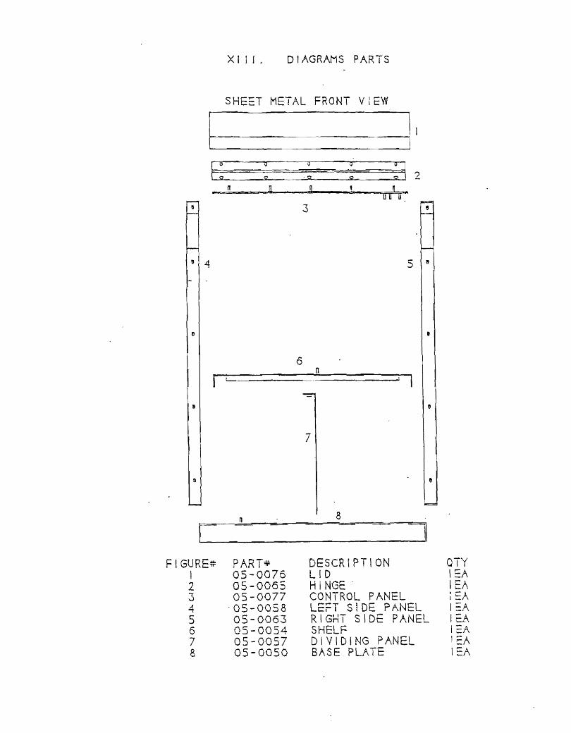
XIII. DIAGRAMS PARTS
SHEET METAL FRONT VIEW
cc: \J ,,; tI
I ( s:z ; '5:2 SO! S! 2 It U g
u u ij
3
" 4 5 8
t
6 11
~ ~------------------~' I
r: FIGURE#
I 2 3 4 5 6 7 8
PART* 05-0076 05-0065 05-0077
'05-0058 05-0G63 05-0054 05-0057 05-0050
7
8
DESCRIPTION LID HINGE' CONTROL PANEL LEFT SIDE PANEL RIGHT SIDE PANEL SHELF DIVIDING PANEL BASE PLATE
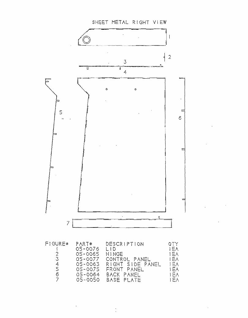
SHEET METAL RIGHT VIEW
~ II -
3 1 2
4
o 0
6
7
FIGUR PART* DESCRIPTION QTY I 05-0076 LID I 2 05-0065 HINGE !r-~
~/\
3 05-0077 CONTROL PANEL lEA 4 05-0063 RIGHT SIDE PANEL I =}\ 5 05-0075 FRONT PANEL lEA 6 05-0064 BACK PAN I E/\ 7 05-0050 BASE PLATE I"" l en.

6 ? I
8 c --'
10 1 1 12 1 .-. -.j
14 15
i/
0 0 0 0 0
-u c
J~ o 1~0 1\>~1 I I I ~? !.!J;-='-
P,\RT;; 20-0073 20-0075 30-0014 ~~-:A0-1 '-'_ IW t:::. 30-0062 33-0012 20-0008 2121 - 0011 33-0051 33-000L 31-0017 13-0017 12-0061 13-0041 13-0072 30-0010 33-0123
I ,I
0 0 0 0-a 0
U 0 0
1FT ION co/'\~c~--o~ · l-\/~C ", ,;::.~:, K !.:J '{ r\ CO~PRESSuR 220VAC ~ UF:--J:----- 1 1 A Nt. r-- 1"""\1 J. r' - - ........ I \ I _::...K _ -: I \1 I r __ J \~ i i L
~LBOV UNION 1/4 NPI VALyr- C' Ir-"-"K 1 / If !:"~-c:.. r1c..L, _ -,.1 I I
NTODLF HEX 1/RM~-1 _I I _ I • wI \l
SOLF'"NO I 0 1 1 5V AC SOLFNOiO 220VAC BARS 1/2Xl/4~PT SLF~VE CRI~P 3/4~ TLI6ING 1/210 i'lUT K~P 6 - 32 8U68L~ /,\OUNT SCREV 6-32Xl/2-"""OL-[ 1 14 - """C1V 1 I?" w . C~A4 _
~UFFLrR BRONZE 1/8 PLUG ALLEN 1/8/'\PT
. L
4t:A EEA
lc.A 1·'=A - '--

FIGURE: 1 1 2 3 4 5 6 '"7 r 8
u I~ 1} P-
c! PART,tt . 20-0072 20-00"14 30-0014 33-0051 31-0021 13-0017 12-0061 13-0041 13-007'2
o o 0 o 0 o o o o a
o o o o o u
o 1'0 Inl I I I
8 !:!! OESCRIPTION OIY V ACUU/,\ PUMP 1 1 5V/\C 1 EA VACUU~ PU~P 220VAC lEA t\UFFLER 1/4t\PT PLASTIC lEA BARB 1/2Xl/4~PT lEA TUBING 1/2 ORAY FLEX 3FT NUT KEP 6-32 8EA 8UBBLF. ~OUNT 4EA SCREV-6-31Xl/2- BEA BOLT 1/4-20Xl/2~ 4EA
-I GlJr.;-" ,- ""'l 1\:-::-
I !
2 .3
L!. ,
5 r o 7 8 a ........
10
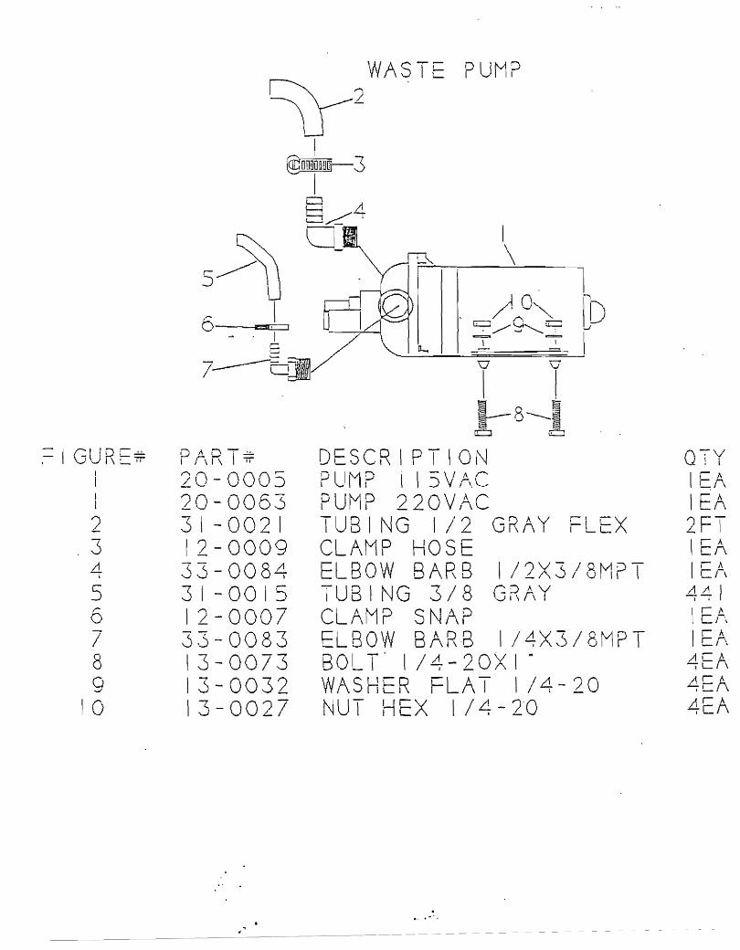
1 ....... ,.\"-:-·· r r\l, I::;;: 20-000 20-006..) 31-0021 12-0009 33-008~ 3 I - 00 IS 12-000/ 3 - 0083 13-0073 13-0032 13-0021
,,'
PUMP
D SCRIPTIO\\J PllMP I \ 5V!\C PUMP ?20V/\C
1 \
I ~
8---~ ~
te:::J
TUBING II? GRAY L X CL/\MP HOS elBOW BARB 1/2X3/8MPT TU8~NG 3/8 GR/\Y CLAMP SNAP
LBO W 81\ R -8 I / ~ X 3 IBM P T BOLT' 1 I~-?OXI" WASHeR rLAT 1/4-?0 NUT H~X I /4 - 2'0
....... ,.
Q:V : I
I /\ I F;\ ?F-- I lEA I -A cr\ ALlI
I !
LirA 1 CA
~EA

-URi...!!. .., .--v ~ u
I
2
L""-a
20-0029 31-001~ 33-0020 13-0017 0/-0033 13-00~1
PR=SSURL SWITCH
O:SCRIPTION SWITCH PReSSURE TUBING I/~ GRAY ~L80W POLY I/~X!/~MPT NUT KL-P 6-32 Q~!CKC-I DOCS~UDC ~WI7L-u Ul\/\ t... .I I\~ v 1\:..- '...I ~ Ii
SCiiEW 6-32XI/2"
n - v ......: I i
'L..~ '-- / ,
2; T I e::..
i_I.
'): /-" j ;- A
I C/-~ ,.... r A
Lcr,

VACUUM CONTAINER
~ 5~~ 15-J ~ II - I _
fG1l-m n n Ill1-r/'I//1 :-1 ~ I \ Lr I· 1
1_. ~ I
i",} 2 I I 4
:.-I =.J
=-.J ,
1-
~ ~ ~/6 7~ ~ ~ :=:;;m ""I
I ~ /-
~;;:..---'"10
l ___ i3
I 0--12 I
o ", 6>!0 \ I I \
-9
FIGURE* PART* DESCRIPTION QTY I 30-0012 CONTAINER VACUUM I~A 2 35-0004 ~ND CAP I" 2::/\ 3 33-0022 ELBOW S \/4NPT 3cA ~ ::3 3 -005 I BARB I 12X I. /4MPT 3c.\ 5 31-0021 TUBI NG 112 GRAY ;=:_=X 1 r:T 6 31-0021 TU8IN~ 1/2 GRAY FLEX 2FT 7 12-0009 CLAMP HOSE 1 E:A 8 07-0094 ~AP FLOAT TUBE BOTTOM I~A '9 07 -00 28 TUB E FLo A T I :::A
10 12-0004 BALL PLASTIC 2~A !! 31-0021 TUBING 1/2 GRAY FLEX 3rT 12 12-0043 BALL ALUMINUM I=A 13 12-0053 RUB8ER BUSHING VACUUM I=A 14 30-0069 VALVE VACUUM I I::A I 5 I 3 - ooa 8 S C K EW CA PSI I 6 - t 8 X I - 4=.A 15 07-0141 CAP FLOAT TUBE TOP I=A

BACK PANEL
FIGURE:;: PAR7~ DESCRIPTION ! 05-0064 BACK PANEL 2 13-00&0 BOLT H~ .3 13-0C32 WASHE~ 1/4 4 \3-0034 W"SHE~ 51 loX I· 5 12-D016 HANDLE BACK 6 07-0001 WASHEi{ 3/4 BLUE 6 07-0001 WASHErt 3/4 RED 7 33-0141 CD F21,ALE POLY 8 20-0023 SWITCH ROCKER LIGHT2D 9 20-0031 CIRCUIT BREAKER ISAMP
10 13-0021 NUT KE? 10-32 II OS-0063 BRACKET CORD 11 13-00..d.) SCRE',v 6- 32X 1/2· 13 13-0017 NUT KE? 6-31 1.:1 20-0013 FAN IISVAC 15 13-0019 NttT K'=:l 8-32 L...
16 20-00\9 RECE?TACL= RECE'SSEn 17 33-0075 BULKHEAD 3/8 I a 20-0021 REcE?TACLE DOUBLE
OTY lEA 2:A 2E:A 2~A lEA lEA lEA 9 2EA lEA lEA 4EA 2E..-\ II::}..
t 0!Q C
IOEA 2SA 2::;\ ISA 1 E-\ lEA
I
[!@~ 18
OOJ ... I
1018 =
13 I§
14
13i§ n IS IS
gg c:=
IcQ
1 I
~ =:x) t 2
II
~~ 17
~) 12
1:iIlZ) I 2
1WZ'.i] I 2
~J 12

REC=SSED RE-CEPTACLE
3 2
g) C lll1Ill11J c::CJ4 c:::CJ5 c::CJS
(Jzzzmm Q)
FIGURE:~ PART:#: DESCRIPTION a-v I I
1 20-0019 RECEPTACLE RECESSED lEA 2 13-0041 S·CREW 6-32XI/2- 2Ef\ 3 13-0017 NUT KEP 6-32 2EA ..d. 21-0033 CONNECTOR SLIDE PI U~ i.-i_ '- lEA 5 2 1 -0034 CONNECTOR SLID~ Y=~LOW 2EJ~

FIGURE=::: 1 2 3 4
COOLING FAN
PART~ DESCRIPTION OTY 20-0013 FAN IISVAC IE.A 1'3-0041 SCREW 6-32XI/2- 4EA i3-0017 NUT KEP 6-32 4EA 2 I -0040 CORD FAN lEA

RECEPTACLE AND WIRE PART LIST
9 4 10
~ 3
~g] W~ .----G ...J iJ . _C:---=:;t]
8 5
E~ QJ ro~ ~ ~~
I ~ I I I~:
?
12 ilZ1rlllrI] -
7 6
Y"'::::>--, [J@ ~~ ~ " ~ -'- ~
:91 ~~ I'
~~
7 6
rfE om @~ " ~ \.- ~
.,r-------'
13
FIGURE;:: PART:;: DESCR I PT ION OTY I 20-0021 RECEPTACLE DOUBLE I E/\ 2 13-0041 SCREW 6-32XI/2"' lEA ~ 21-0082 SOCKET 20-14 AWG 18E/\ ~
4 2 1-0078 SOCKET HOUSING 3 PIN lEA --. 21-0079 SOCKET HOUSING 4 PIN lEA -'
6 21-0080 SOCKET HOUSING 6 P 1 ~J 2EA 7 2 1-0077 P.I N HOUSING 6 PIN 2EA 8 21-0076 PIN HOUSING 4 PIN lEA 9 2 I -0075 PIN HOUSING 3 PIN lEA
10 21-0081 PIN 20-14 AWG 18ci\ 1 I 2 1 - 000 I WI RE BLACK 14 AWG 2FT 12 21-0002 WIRE WHITE 14 AWG 8FT 13 21-0005 WIRE ORANGE 14 AWG 20FT
NOTE: NOT TO BE USED AS ELECTRICAL SCHEMATIC

\GURE* I 2 3 ~
FOO! CONTROl
PART~ 30-0026 12-0020 05-0075 3 I -00 I 9
2
DESCRIPTION FOOT CONTROL SNAP BUSHING 1/2-FRONT PANEL TUBING FOOT CONTROL
OTY I :- A cr\
I r ). cr\ I ,- .\ cr\
r 1 I N o I I

I = =
1 1
FIGURE~ ! 2 ..)
~ 5
HANDPIECE HOLDERS
LEFT
o 6.R-1 -!!.. I f\ -:-:-
13-0017 12-00~8 13-0050 30 - 0 1 10 30-0001
::::r =
) C- __ ~\ll :-~GHT d
5
Of=SCRIPTION NUT KEP 6-32 BAR HOLDER HANDPIECE SCREW 6-32XXI-HOLDER ·Hr\NDP \ ECE HOLDER UN1YcRSAL
1 1
QTY A .- A -oCt\
.;1-~ t::/~ ....., r ~ ..:) cr, --A -..)Ci\

~J EDLE V!\LV::" \VATER 3~/\
~ i
0 2 ~3 ~4
sm I JO-1'1 u
6IDl 7
0 U8
.Irl !!"!.!!.. I[V\.;r\t:..-:- PART..u.
I r\1 "... D SCRIPTION QTY 3!-OOO~ UBING 1/8" !"'\! U' cL .t: 6-1/21N
2 13-009 SLEVE 1/810 r-CA .L'-..i \
3 33-0058 B,\R8 1/!6XtO ... 32 2:-/\ L'. 13-0036 WASHER WHIT~ 10-32 2=A ,....
30-0028 VALVE NE~DL~ I A ~ I
0 12-0023 KNOB I r. i\
7 31-0023 TUBING ~ HOLE 551N 8 30-004~ TERMINAL 4 HOl I A
J \

.;.. • :""'! ., .. ~'. •
FIGURE ,
2 ..)
L!. ,
5 6 / 8
SWITCH WASTE PUMP\VACUUM PUMP
d2
I ~ __ ----l..--'
PART* 20-0017 21 -0033 2 1- 0031 21 -0023 21 - 008 I 21-0076 21-0079 21-0082
2
DESCRIPTION SWITCH TOGGL SPST CONNECTOR FORK gLUE CONNECTOR 8U T BLUe CONNECTOR BUTT YELLOW PIN 20- I ~ 'AWG PlN HOUSING 4 PIN SOCKET HOUSING ~ PlN SOCK T 20-' 4 AWG
QTY ?=A _ L-
2EA lEA I .- A c/\
A r A .c:r\ I El\ I r 1\
C/"\
~ c/\

FIGURE# I 2 3 .4
I
5
RIGHT SID PANEL
5 .d. 3 n ~
"'.: .
PART# 05-0063 12-00~9 13-0034 \3-0032 12-0081
I '
2"
o e'
e l
DESCR I PT I OJ\} RIGHT SIDE P ;\N HANDLE SIDE WASHER 5/ 16·X I" WASHER 1/4 BOLT M6- IXI8
QTY L I El\
lEA 2EA 2 I"'Ir-A L CJ \

FIGURE~ I 2 3 4 :J
6 7 8 9
10 I I 12 13 14 15
· , .. _ ...... ':::.~-.......... w - 4'
LEFT SIDE PANEL
I
2 345
~ n ~
10
IIIQ I 1
lJ PART~ DESCRIPTION 05-0058 L-C:-t:. I SIDE PANEL 12-0049 HANDLE SIDE 13-0034 WASHER S/16XI-13-0032 WASHER 1/4 12-0056 CLAMP CABLE [/2-12-0081 BOLT M6- IXI a 2 1-0039 ELECTRICAL BOX 13-0019 NUT KEP 8-32 20-0021 RECEPTACLE DOUBLE 21-0043 COVER RECEPTACLE 13-0049 SCREW 6-32XI/2-21-0082 SOCKET 20-14 AWG 21-0078 SOCKET HOUSING "1
.....;
21-0075 PIN HOUSING 3 PIN 21-0081 PIN 20-14 AWG
OTY lEA I t:l\ ?-II ..... ::./'\ .., .... 2EA 2E,A\ lEA A ..... A "'7C I El\ I Ei\ lEA 3El~
PIN I Er\ lEA 3EA
"

FiGURE: 1 2 3 4 5 6 "'"7 r 8. o -.I
10 1 1 12 13 14 15 16
REPAIR KI
1 §
21
4 --)
10 ~
. 11 (tl,
t 2 [;
l3===~§
14 ..
15 I
16 0
PART;; 13-0017 13-0019 13-0036. 13-0'2141 13-0043 13-0094 13-0095 33-0002 33-0058 33-0060 33-0065 33-0067 90-0026 90-0065 90-21066 90-0067
DESCRIFTION NU- K-- f"'"'o - ..... I I t:..r' Q - ..j c: NUT KEP 8;'32 ~ASHER VHITc i0-32 SCREV 6-32X1/2" SCREV 8-32Xl/2" Sl FrVE 1/810 SLEt-VE 1/410 NUT POLY SLEVE 1/4~ BARB 1/16X10-32 BAPE 1/8X10-SLEFVE POLY 1/4
8
COLF="CT 3/6 seREV DRIVER O-RING SYRINGE S~ ALL~N VRENCH 1/16" O-RING SYRINGE LG
IGUR I.
I 2 3
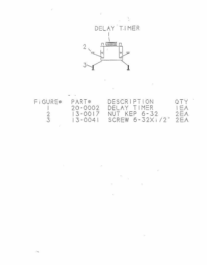
DEL/\ Y T-I MF R I \
? n lOlIIITIITJTI n
-~=~ rv 3,--~ )
D"DT~ I f\1\ "7t" DESCRIPTiON 20-0002 DELAY TIM~R 13-0017 NUT K~P 6-32 13-00/11 \ SCReW 6-~?VI/?" 0_A _
Q v I
I r A C/\ ?C" -~!""\
"" ," L r\
• .t~ . .. ::..
1-5 c-6 I
KEY :-7
~o
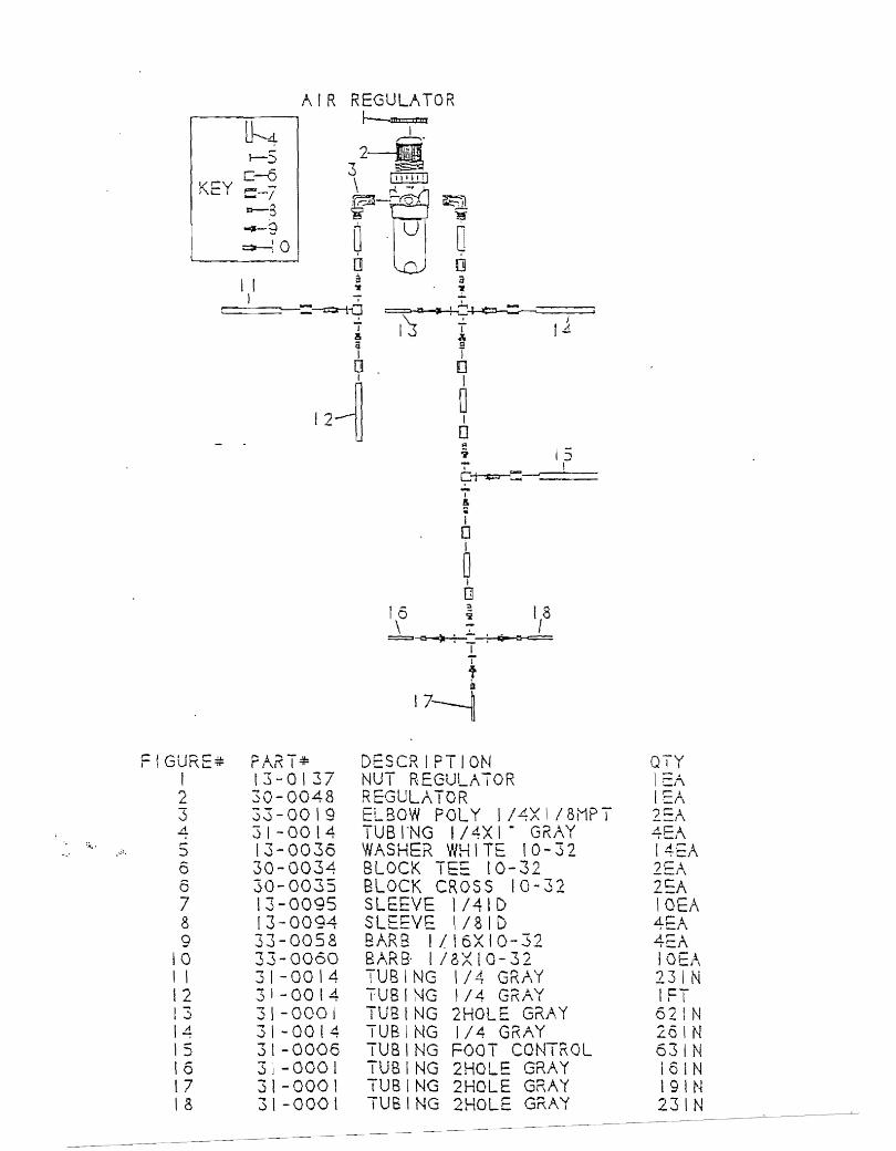
FIGURE* PART* I 13-0137 2 30-0048 <: 33-00\9 v
4 31-0014 ,... 13-0036 ~
6 30-0034 6 30-0035 7 13-0095 8 13-0094 9 33-0058
10 33-0060 \ I 31-0014 12 3 , - 00 14 13 31-0001 14 31 - 00 I 4 15 3l -0006 16 3J -0001 17 31-000 I 18 31-0001
DESCRIPTION NUT REGULATOR REGULATOR EL80W POLY 1/4XI/8MPT TUB I-NG I 14X I" GRAY WASHER WHITE lO-32 BLOCK .... c.,.....
I ..... ::: 10-32 BLOCK CROSS 10-32 SLEEVE \/41D SLEEVE I/~ID BARB 1/16XIO-32 BARB· 1/8XIO-32 TUBING 1/4 GRr\Y TUBING 1/4 GRAY TU81NG 2HOLE. GRAY TUBING 1/4 GRAY TUBING FOOT CONTROL TUBING 2HOLE GRAY TUBING 2HOlE GRAY TUBING 2HOLE GRAY
QIY \ =,~ I ::r\ 2::A
!4EA lEA 2EA IOEA 4EA 4EA IOEJ-\ 231N 1FT 62lN 2alN 631N loIN 19lN 231N

WATER RELAY/TRI-3LOCK
c:::::::
I 6 2
.-; 7
\J ~ 3
FIGUR~~ DART.J.1. l!\ ,,- DESCRIPTION Q7V I I
I 13-0049 SCREW 6-32XI/2- ":--".1, )-~
...!..._l\
" 05-0069 BRACK::T TRI-BLOCK I - A
.:::. I =r, 3 13-001'7 NUT K;::~ 6-32 ""- .. /-,..
l.- I - _1,\
L! 13-0039 SCREW 4-4GXI/4- /,-r -= \ j 30-0033 TRI-BLOCK I Cl~\ 6 30-0036 Wi\ TER RELAY lEA 7 13-001 I SCREW 4-40XI/4- 2'=/\

VACUUM SOLIDS TR/\P
I 3 4 ! I 2 ! tJ ()a::Ir
OJ r g I c-. g UUIJ Cl
7 5
6
IGURE~ DA-'""'T.u. I I K "IT' DESeR!p ION QTV t I
I 30-0095 V/~CUUM SOLIDS Tr...,,,,, Kr.1' I-A t:: t\
2 13-0049 SCREW 6-32X/12" ""'r-A .L=A
3 07-0142 BRACKET SOL I DS' TK/~P I EJ\ 4 13-0017 NUT KC-LI 6-32 ;icA --;-t_
5 3 \ - 00 15 TUBING 3/8 GRAY 571N 6 3 ! - 002 I TUBING 1/2 - 10 GRAY 1FT --r
31-0021 TUBING 1/2" 10 GRAY 571N I 8 30-0017 IIVr-tl C VALVE 1 E/\ 9 30-0013 S;\LIY,\ EJECTOR V /\l VE IrA
! ~ \

CIGU~C= I 'K. '- " I
2 3 4 5
HANDPIECE PRESSURE GAUGE
DA:"-l== I d"{ .,
30-0022 13-0036 33-0058 13-0094 31 -0008
=2
o 4
o 4
DESCRIPTION GAUGE PANEL MOUNT 100 WASHER WHITE 10-32 BARB 1"/16X10-32' SLEEVE !/BID TUBING 1/8 ORANGE
QTY I rA
t:.i\
I =-,-\ I ?-.1 _=1\
61N
IreI!J
01
2
=2
PI = 87
[]
9
0 8
a 7 ~
? =-
60
=0 2
E;7 b
.... 4 "
~ 0
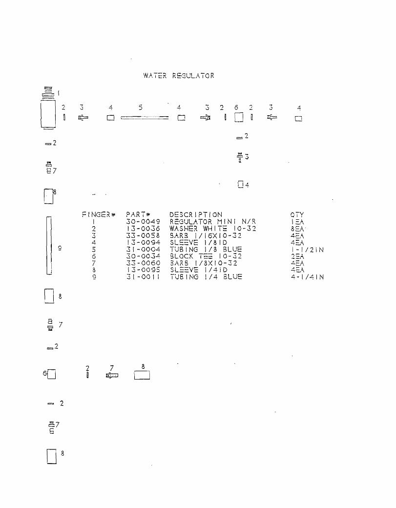
FINGcr<"H= I 2 3 4 5 6 7 B 9
? 7 [ ¢:J
5
PART~ 30-0049 13-0036 33-0058 13-0094 3 1-0004 30-003..1 33-0060 \3-0095 3 t -00 I I
8
0
4- 3 2 6 /
[J ~ n .,
=-
~3 ::I.
114
DESCRIPTION R2GULATOR MINI N/~ WASHER WHITE 10-32 SARa 1/16XIO-32 SLE:=VE 1/31D TUBING 1/8 BLUE 3LOCK T== 10-32 3ARS !/3XI0-32 SL==VE I 14 ! D TUSING 1/4 BLUE
3 ~
4
0
eTY 1::/\ SEA" 4~}\ A .... ~
-=-::.~
1 -1/21 N "',.... )--.
~=A ,.-. -=-="i. 4-1/41N
FIGUREJI I 2 3 4 S 6 7 !
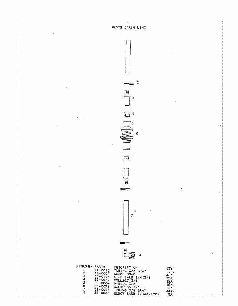
PART", 31-<)015 12-0007 33-<>10.4. 33-0067 9O-<J004 33-0076 31-00[6 33-00a3
WASTE CRAIN LINE
c::::- 2
c t::t '--' rr =4 ill
c:=: -:;, ,..=-
~ 6 L :::z:;::::
;:=;:::; "'---
""'----'
m =
n E 0
~
7
OEseR I PT ION TUB I NG 3/8 GaAY C:".AMP SNAP STEM BARS JJ4X3/S COLLECT 3./a \i-RING 3/8 aULXHEJ\O 3/ a TUSING 3/3 GRAY ELBOW SARB
OTY [2F7 Jc:. .... 2£ .... 2£.l... 2EA lEA 4AN

CONTROL PANEL aD BLUE
~ 0 ~ I I
~
. .--.. ..... '--/
~3 o 4
85 9
6 -~7
_6
AS c
IY
~8 04
8 r-'=i=:J
4 5 6 -6 6 5 4
0 ~ 0' 9
eo 0'
FIGURE7= PART* DESCR I PT I ON a-v I I
I 33-0141 00 FeMALE POLY 1 ::l\ 2 07-0001 WASHEK BLUE I ~/\ ~ 31 -00 I I TUBING 1/4 BLUE I IN ~
..d. 13-0095 SLE=VE l/41D S~J~\ ~ 33-0060 Bf,RB 1/8XIO-32 --,I.
2)::/\
6 13-0036 WASHEr<. WHITe 10-32 SCI" 7 30-0067 CHECK VALVE 10-32 I =J-\ 8 31 -00 I I TUBING 1/4 BLUE I IN 9 30-0034 BLOCK TEE 10-32 I E,A

3
D ~IGU:\;-~ I 'f\C-;-r PIlDT~ r\ I \ -:-r DFSCRIPTION ro..-v
U I I
I 33-01~! QD i-'M~L I C 1\ :10' V I '_ i 1-;" =r\
? 07-0002 W"C:WCR f\v I II-I DeD 1\ t- I A
3 31 -001 TUBING 1/ A\. G=>"Y '1 \ 1\ giN 4 13-0095 SLE:V~ I/~ID '~A
d _ t"

FIGURE DADT~ DESCRIPTION OTY I f\i \ ":"I'"
I 30-00 I I CONTAINER W>'-:-~i' leA - _ .... 1\ ! :"""1 \ L..r\
2 33-0142 OD POLY I/~ ·M/\LE ?Cl _ L.. \
3 31-0012 TUBING I/~ RED 61N L!. 33-0020 ELBOW POLY 1/4X'/~MPT 2EA I
5 33-0102 BARB I/~XI/2MPT lEA 6 3 \ - 00 15 TUBING 3/8 Gr.Ay giN "'Kr\ 7 31 -00 I I TUBING \/~ BLUE 6lN
..
I\~~' -B .) 1. ::: c
I
~5
6
FIGURE# I 2 3 4 5 6 7 8 9
10 I I 12 13
1-
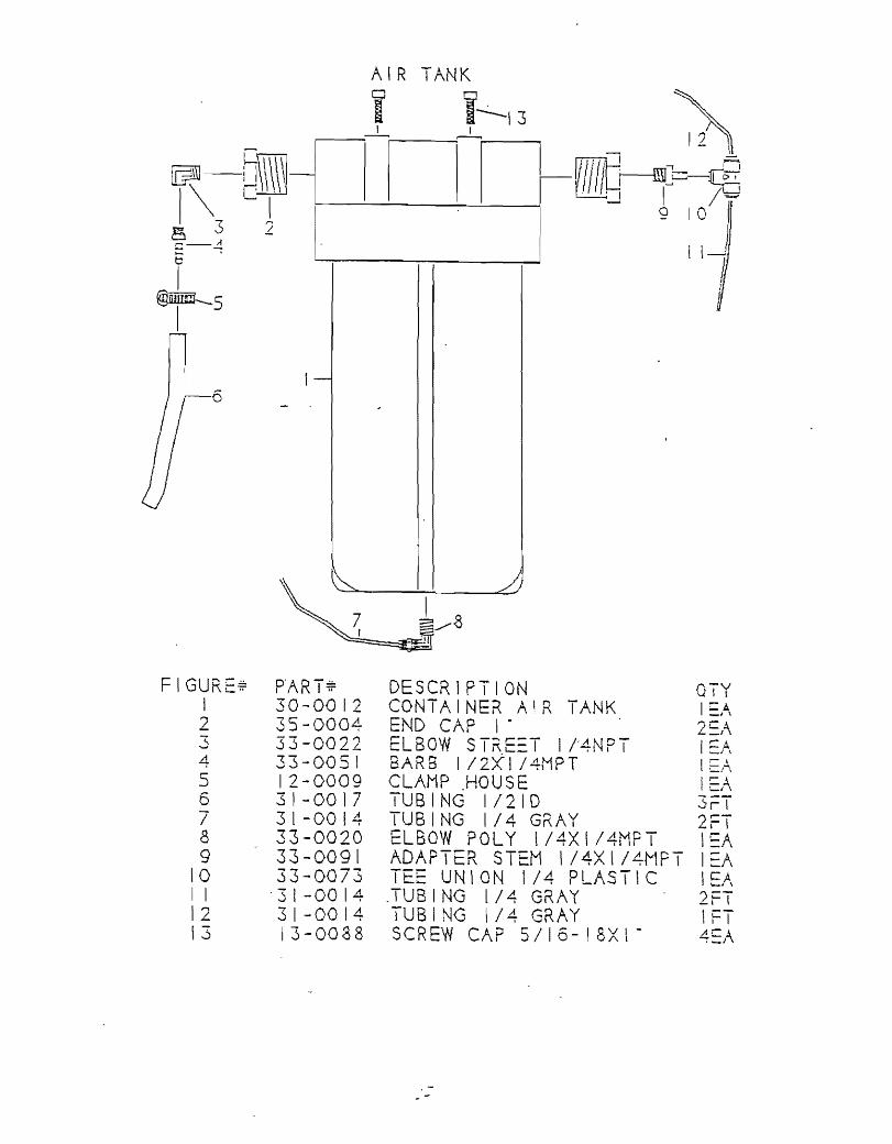
D'AR-::!:!:; I I .. 30-0012 35-0004 33-0022 33-0051 12-0009 3 I -00 17 31-0014 33-0020 33-009\ 33-0073
. 3 1-00 14 31-0014 \3-0088
J
DESCRIPTlON OTY CONTAINER AIR TANK lEA END CAP I· 2~/\ ELBOW ST~E=T 1l4NPT I :: . .A, BARB 1/2~1/4MPT tEA CLAMP .HOU S E 1=,-\ TUBING 1/210 3rT TUBING 1/4 GRAY 2FT ELBOW POLY \/4X1/4MPT I~A ADAPTER STEM \/4XI/4MPT I=A TEE UNION 1/4 PLASTIC lEA .TUB 1 NG l/4 GRAY 2FT TUB I NG \ 1 4 GRAY 1 FT S CREW CAP 5 I I 6 - I 8 X \ - 4 ::)\


![t] - NISCAIRnopr.niscair.res.in/bitstream/123456789/53697/1/IJCA 14A...Ep V ip (Lamp 1·0 0·1 1'0 0'1 1'0 0'1 1'0 0'1 1'0 0'1 0'1, KCl do 0'094, NaCiO, do 0'1, KNO. do Acetate buffer](https://img.pdfslide.net/doc/110x75/6112226529051a7b0b070e83/t-14a-ep-v-ip-lamp-10-01-10-01-10-01-10-01-10-01-01-kcl-do-0094.jpg)