Embed Size (px)
Citation preview

ffi
a
i
TECHNECAT SERYICE
GENERATOROUTPUT CONTROI.
UNITS
OPERATI ON-CONSTRUCTI O N_SERYI CI N G


INTRODUCTION
Both the Lucas Compensated Voltage and Current Voltage regulating
systems are covered in the accompanying pages of this publication.
In the explanation of the working of Lucas generator output
control units, certain abstruse technical considerations have been
deliberately omitted, but these factors do, of course, have to be
considered by Lucas engineers when designing the equipment. Itshould also be emphasised that our recommendations in regard to
regulator open-circuit voltage settings should always be strictly
adhered to if satisfactory working of the equipment is to be obtained.
Regulators are designed to snit the electrical equipment of each
individual vehicle, i.e., type of generator, lamp and accessory load,
etc., and for this reason are not interchangeable as a whole. Always
refer to a Lucas Interchangeability List before fitting a replacement.
The mention of any unit, or parts of a unit does not imply the
availability of either the complete unit or spare parts for service
purposes.
Page 3
C0NTEf.ITS
PART 1.
Why control of the generator outpttt is necessary.
The Principles of Voltage Control.The construction of the control unit.Voltage control in practice - the voltage regulator.The cutout.A theoretical constant voltage control charging circuit.
Compensated Voltage Control.Why compensation is necessary.The regulator series and load uindings.The charging circuit employing the Lucas C.V.C. system'Temperature com pensation.Auxiliary circuits - the complete colrtrol box.
PART 2.
Control Boxes: S1'mbols. T1'pcs :lnd Applications, Service Adjustments.
Symbols.Features or tl:e R F.95 . 9(r, 97, RB. I 07, RB. I 08, RB. 1 06/ l. RB. I 06/2 controlboxes.Reguletor nrc'chattical settings and contact cleaning.Cut-,rri1 tnechanrcul settings and contact sets.T llc ru'rlulrtlor poirit: resistor.Frusr,' unils. FS5 -5lF and 4JF.
PAIIT 3.
Chccking the Charging System.
Conrplete test procedure for the charging system, comprising battery andgenerirror tests. checking of the regulator, electrical setting; checkingcrit-out operation. warning light, ammeter. Possible faults are indicatedat each stage.
I'AiiT ;1
Currcnt Voltage Regulators.
Reasons for the introduction of the current/voltage system.Charging characteristics of the compensated voltage and current/voltagesystems.The RB.3l0 and 6GC current-voltage regulator - build-up of the unit.Circuits of the Lucas current/voltage regulator; method of operation.Construction details of the RB.310,6GC and RB.340 control boxes.Charging troubles - Checking and adjusting current voltage regulators.
@ Printed in England.
JOSEPH LUCAS (SALES & SERVICE) LTD., BIRMINGHAIVI 18, ENCLAND.
Page 4

PART ONE
Working Principles
GENERATOR OUTPUT CONTROLThe generator with which we are concerned is a
plain, shunt-connected machine. The main charac-teristic of this type of generator is that its output risesr.vith increasing speed and is by itself totally unsuitable
that on modern vehicles
is therelore necessary, when it is applied to a vehicle asthe source of the battery charging current, if it is tofunction efficientll, at all road speeds. To functionefficiently i1 6ust not only be controlled over thespeed range but also give an output which variesaccording tc th- load on the battery and its state ofcharge.
CONSTANT VOLTAGE CONTROLThe answer to the problem of how to control the
generator output, so that at all times the battery isbeing correctly charged and the generator keptwithin its rated output, is the fact that the batteryvoltage (and consequently the back E.N{.F.) variesaccording to its state of charge. If now we couldcontrol the generator terminal volta_qe at a pre-setfigure over a wide speed range, we should have avariable voltage at one end of our charging system anda constant voltage at the other. The current florvingin this charging circuit would therefore vary rvith thevarying terminal voltage of the battery, i.e.. rvith its
APPROXIMATE EATTERY VOLTAGE: DISCHARGED
; FULLY CHANGED
GENEPATOR VOLTAGE CONTROLLEO AT 16V,
state of charge. The difference between the batteryterminal voltage and the generator terminal voltagewould be appreciable when the battery was in a lowstate ofcharge, getting progressively less as the batteryreached its fully-charged state. lf the pre-determinedvoltage at the generator terminals has been correctlyset. in theory rve shall arrive at a state where thebattery terminal voltage in its fully charged conditionwill exactly equal the generator terminal voltage. Atthis point, no current will flow through the chargingcircuit, as the back E.M.F. of the battery will equalthe terminal voltage of the generator.
THE CONSTRUCTION OF:THE CONTROLUNIT
As shown in the illustration below, the voltagecontrol unit comprises an iron frame or "Yoke" (1)on which is mounted two iron bobbin cores (2)one (left) the voltage regulator and the other (right)the cut-out switch.
Consider the voltage regulator unit: a pivoted(bell-crank) armature (3) is attached by means of aspring blade (4) to the top of the iron frame. Thehorizontal member (5) lies immediately over thebobbin core and when this core is magnetised theflat member will be drawn down to it. In order toprevent it clinging to the core by residual magnetisma brass plate (6) or a copper button prevents iron toiron contact. (Continued on next page).
nI
CHARGI NG CHARACTERISTICSThe graph below shows how the charging rate
falls as the battery reaches its fully-charged state,becoming a trickle charge, in this case of I or 2 amps.,after 10 hours.
It is also clear that with this system of regulation"Voltage Control" the battery receives a high chargefrom the generator when it needs it most.
:
o
2
GENERATOP PPESSUPE BATTERY BACK PRESSURE
Page 5

THE GENERATOR FIELD CIRCUITThe output of the shunt-wound generator is only
obtained when the field circuit is joined in parallelwith the armature circuit, i.e., when terminals D andF are connected together. By breaking this DiFconnexion, that is, breaking the field circuit, thegenerator output will immediately fall off.
The illustration on the right shows the regulatorframe and its connexion to the generator. Byfollowing the circuit from the generator D terminal,through the right-angle frame and moving contact tothe fixed contact, and back to F at the generator.it can be seen that D is effectivelyjoined to F through apair of contacts. Spring tension holds the contactsiogether, thus keeping the D/F circuit closed.
THE CONSTRUCTION OF THE CONTROLUNIT (continued)
On the vertical member of this armature a contactpoint (7) is fixed to line up with a stationary contact(8) insulated from the main bracket. Also on thevertical member of the armature is a spring blade(9) and this blade lines up with an adjusting screw (10).By means of this adjusting screw the pressure betweenthe two contact points may be varied.
The main D terminal of the generator connectsto the bracket as shown (11) and the generator field
terminal F connects to the insulated contact point (8).When at rest the two contact points will be closed,thus completing the circuit between the generatorarmature and field.
The contact point assembly of the automatic cut-outswitch (12) is of a generally similqr constructiori buta single opening and closing operation disconnects andconnects the generator from the battery. In the restposition the cut-out points are open whereas the fieldregulator points are closed.
REGULATOR SHUNT COILThe breaking of the contacts is controlled by an
electro-magnetic relay whose winding is connectedacross the generator between terminal D and earth,that is, in parallel with the generator armature. Thus,as the generator voltage rises, this shunt windingwill be energised, magnetising the core, and a pointwill be reached when the magnetic pull of the core isstrong enough to overcome the spring tension andseparate the contacts.
Immediately the contacts separate, breaking thefield circuit, the voltage of the generator falls. Inturn, the bobbin will lose its magnetic pull, releasethe moving contact and, with the field circuit againcompleted, the generator output will rise.
When in operation this becomes an alternate rapid llopening and closing of the contacts at a frequency ofllbetween 15 and 30 times per second enabling a very l!fine regulation of the generator voltage to be obtained. ,l I
The voltage necessary to create sufficient magneticeffect to separate the contacts can now be controlledby the spring tension on the contacts themselves.Thus we can control our generator voltage at a pre-setfigure by adjustment of the spring tension. Andwhat is more, this control is independent of the speedat which the generator is being driven.
Page 6
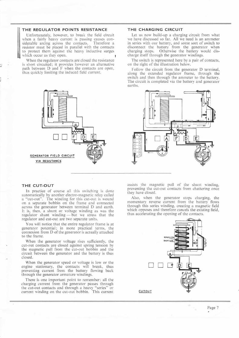
THE REGULATOR POINTS RESISTANCEUnfortunately, however, to break the field circuit
when a fairly heavy current is passing causes con-siderable arcing across the contacts. Therefore aresistor must be placed in parallel with the contactsto protect them against the heavy inductive surgeswhich occur as they open. t
When the regulator contacts are closed the resistanceis short circuited; it provides however an alternativepath between D and F when the contacts are open,thus quickly limiting the induced field current.
trrGENERATOR FrELp CIRCU1I
VIA RESISTANCE
THE CUT.OUTIn practice of course all this switching is done
automatically by another electro-magnetic relay calleda 'ocut-out". The winding for this cut-out is woundon a separate bobbin on the frame and connectedacross the generator between terminal D and earth.It is, then, a shunt or voltage winding as was theregulator shunt winding - but we stress that theregulator and cut-out are two separate units.
You will notice that the entire regulator frame is atgenerator potential; in more practical terms, theconnexion from D of the generator is actually attachedto the frame.
When the generator voltage rises sufficiently, thecut-out contacts are closed against spring tension bythe magnetic pull from the cut-out bobbin and thecircuit between the generator and the battery is thusclosed.
When the generator speed or voltage is low or theengine stationary, the contacts will break, thuspreventing current from the battery flowing backthrough the generator armature windings.
There is one important point to remember: all thecharging current from the generator passes throughthe cut-out contacts and through a heavy "series" orcurrent winding on the cut-out bobbin. This current
THE CHARGING CIRCUITLet us now build-up a charging circuit from what
we have discussed so far. Al1 we need is an ammeterin series with our battery, and some sort of switch todisconnect the battery from the generator whencharging stops. Otherwise the battery would dis-charge itself through the generator windings.
The switch is represented here by a pair of contacts,on the right of the illustration below.
Follow the circuit from the generator D terminal,along the extended regulator frame, through theswitch and then through the ammeter to the battery.The circuit is completed via the battery and generatorearths.
assists the magnetic pull of the shunt winding,preventing the cut-out contacts from chattering oncethey have closed.
Also, when the generator stops charging, themomentary reverse current from the battery flowsthrough this series winding, creating a magnetic fleldwhich opposes and therefore cancels the existing field,thus accelerating the opening of the contacts.
xtrrl
CUTOUT
P.age 7

CHARGING CIRCUIT: "CONSTANTVOLTAGE CONTROL"
The regulator and cut-out assembly, that is, thecontrol box, would now look like this. Follow thecircuit through, starting at the D terminal of thegenerator, from there to the D terminal of the boxand then to the regulator frame, through the cut-outwhen the contacts close, through the heavy serieswinding on the cut-out and across to terminal A.This telminal is connected via the ammeter to thebattery. The circuit is completed by the battery andgenerator earths.
Unfortunately, this simple "constant voltage con'lrol" system has one snag: it presupposes the useof a generator of very great generating capacity.Consider the case of a battery in a low state of charge,its terminal voltage will be low. If, in addition, aload is put on the battery, switch the headlamps onfor instance, the voltage will fall still lower. Undersuch conditions, the generator will still endeavour tomaintain the pre-determined voltage set by theregulator and consequently an extremely heavycuirent will flow in the charging circuit, owing to thesubstantial difference between the battery and genera-tor voltages. In practice this current would besufficient to burn out the armature of a standardautomobile generator.
..COMPENSATED VOLTAGE CONTROL''The Lucas "COMPENSATED Voltage Control
System" overcomes this difficulty by automaticallyvarying the OPERATIONAL voltage setting of theregulator, so that the difference between the generatorand battery terminal voltages is never great enough tocause such a heavy current to flow that the generatorwould be damaged.
THE REGULATOR SERIES WINDINGIn practice, this variation in the operating voltage
of the regulator is brought about by adding anotherwinding to the regulator bobbin. In other words, thecharging circuit now continues from the cut-outseries winding, not direct to terminal A, but throughan additional "Series" winding on the regulatorbobbin. This winding thus carries all charging currentflowing from the generator to the battery and is woundso that its magnetic field assists that of the voltage orshunt coil ofthe regulator in pulling apart the regulatorcontacts. The heavier the current flowing, the greaterwill be the magnetic pull of the bobbin, and the soonerthe contacts will open. Thus in effect we have loweredthe voltage at which regulation occurs: our generatorwill then be working at an operational voltage whichis varied according to the current flowing into thebattery.
As the battery becomes discharged and its voltagefalls the charging circuit voltage or "LINE VOLT-AGE" will also fall. The action of the COM-PENSATING or SERIES winding on the regulatoris thus to limit the charging current to the maximumsafe output of the generator.
Page 8
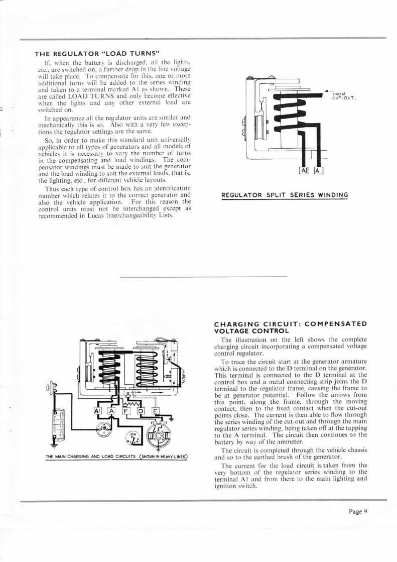
THE REGULATOR "LOAD TURNS"If, when the battery is discharged, all the lights,
etc., are switched on, a further drop in the line voltagewill take place. To compensate for this. one or moreadditional turns will be added to the series u'indingand taken to a terminal marked A1 as shown. Theseare called LOAD TURNS and only'become effectivervhen the lights and any other external load areswitched on.
In appearance all the regulator units are similar andmechanically this is so. Also with a very few excep-tions the regulator settings are the sanle.
So, in order to make this standard unit universallyapplicable to all types of generators and all models ofvehicles it is necessary to vary the number of turnsin the compensating and load windings. The com-pensator windings must be made to suit the generatorand the load winding to suit the external loads, that is,the lighting, etc., for different vehicle layouts.
Thus each type of control box has an identificationnumber which relates it to the correct generator andalso the vehicle application. For this reason thecontrol units must not be interchanged except as
recommended in Lucas Interchangeability Lists.
REGULATOR SPLIT SERIES WINDING
CHARGING CIRCUIT: COMPENSATEDVOLTAGE CONTROL
The illustration on the left shows the completecharging circuit incorporating a compensated voltagecontrol regulator.
To trace the circuit start at the generator armaturewhich is connected to the D terminal on the generator.This terminal is connected to the D terminal at thecontrol box and a metal connecting strip joins the Dterminal to the regulator frame, causing the frame tobe at generator potential. Follow the arrows fromthis point, along the frame, through the movingcontact, then to the fixed contact when the cut-outpoints close. The current is then able to flow throughihe series winding of the cut-out and through the mainregulator series winding, being taken off at the tappingto the A terminal. The circuit then continues to thebattery by way of the ammeter.
The circuit is completed through the vehicle chassisand so to the earthed brush of the generator.
The current for the load circuit is taken from thevery bottom of the regulator series winding to theterminal Al and from there to the main lighting andignition switch.
CHAPGING aNo uolo crpcurrs (sxovt rn xeew lrxes)
Page 9

TEMPERATU RE COMPENSATIONThe regulators themselves, in addition to having
compensating and load turns, are also TEMPERA-TURE compensated. This, like the regulator setting,is common to them all, but is not in any way adjustable.
Put in its simplest form, this temperature com-pensation aims primarily to make the generatorvoltage-setting follow the comparative battery voltageas it rises and falls due to marked temperature changes.
As the charge proceeds, the generator will heat upquickly. The temperature compensating featureenables an extra high charge rate to be applied to thebattery with a cold generator and be maintained untilthe generator reaches its maximum working tempera-ture, when the generator voltage is automaticallyreduced by the compensator and the charge proceedsat a normal rate.
To this end, as shown in the illustration, a bi-metalstrip is fitted behind the contact tensioning spring.This consists of two strips of metal with differentco-efficients of expansion welded together and thecombination, when heated, will give a differing degreeof expansion, causing the combination to bend as thetemperature rises and resume its normal shape when
AUXILIARY IGNITION AND ACCESSORIES CIRCUIT
REGULATOR LOCKNUTADJUSTING SCREW
BI. M EIALsrRr P,
BI.METAL STRIP FITTED BEHINDCONTACT TENSIONING SPRING
the temperature falls. Having then applied such acombination of metals to the regulator adjustingspring, a spring tension is obtained which will varyautomatically with the temperature of the equipment.The controlling voltage of the regulator will thus behigher when it is cold than when it is hot.
Like the regulator, operation of the cut-out istemperature-controlled by means of a bi-metallictensioning spring.
AUXILIARY CIRCUITSThe regulator unit itself is now complete, but there
are other features of the control box which must beconsidered.
On some control boxes, additional terminals areprovided to cater for accessories fltted on the vehicle,such as trafficators, windscreen wipers, etc.
Extra terminals on this type of box are, flrst: theA2 terminal. This, as you can see, is connectedfrom the Al terminal through a fuse marked "AUX"(auxiliary). Any accessories connected to this ter-minal will be fed from the battery via the ammeterthrough the load turns on the regulator bobbin, witha fuse in circuit.
Next, the ,A.3 and ,A.4 terminals. The A3 terminal isfed from the ignition switch, and is thus "live"only when the ignition switch is on. Both A4 terminalsare then fed through a fuse from A3. Thus auxiliariesconnected to ,A.4 will only operate when the ignitionis switched on. The feed to the ignition switch itselfis from A1, i.e., through the LOAD turns.
THE COMPLETE CONTROL BOXMost of the features discussed are indicated in this
illustration, which shows the two auxiliary fuses, andthe right angle bracket or yoke on which both regulatorand cut-out are mounted, regulator left, cut-oui right.
The regulator split-series winding is pointed out;and the screws for adjusting the spring tension on theregulator and cut-out.
SCREWS SECURINGFIXED CONTACT PLATE
SPLIT SERIESWINDING
FUSES
COMPENSATED VOLTAGE CONTROL REGULATOR
Page l0
PART TWO
Control Boxe Symbols, Types and Application
IDENTIFICATION SYMBOLSRBl06/1 Regulator Box, incorporatin_e LRTg 12 regu-
lator. Shrouded terminals.RB106/2 As RB106/1, but wirh built-in regulator.RBl07 Regulator Box, incorporating built-in regu-
lator sealed cover.RB108 As RBl07, but with riveted cover. Some
versions have rubber mounting studs.RB3l0 Current Voltage Control Box, 3 terminals
(B, F, D).
!F952 95' RBt07' RB108, RB105/1 AND R8106/2CONTROL BOXES
We can now review the Control Boxes themselves.In this particular section we will deal r.vith compensatedvoltage control units only.
To begin with, what are their characteristic features ?With the exception of the RF95/3, RBl07, RB108 andRB106i2 the LRT9 regulator is used with a variety ofseries windings, but the voltage settings are sometimesspecial for particular applications.
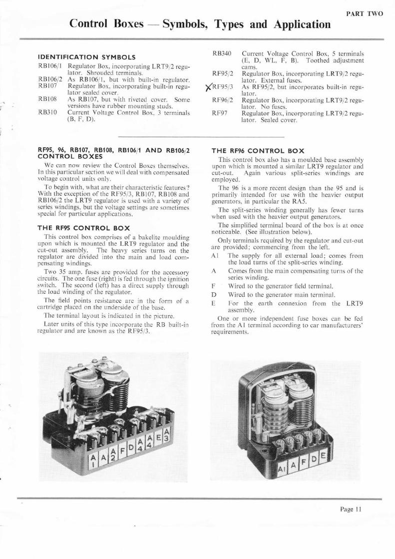
THE RF95 CONTROL BOXThis control box comprises of a bakelite rnoulding
upon which is mounted the LRTS regulator and thecut-out assenrbly. The heavy series turns on theregulator are divided into the main and load com-pensating windings.
Two 35 amp. fuses are provided lor the accessorycircuits. The one fuse (right) is fed through the ignitionswitch. The second (left) has a direcr supply throughthe load winding ol the regulator.
The fleld points resistance are in the form of acartridge placed on the underside of the base.
The terminal layout is indicated in the picture.Later units of this type incorporate the RB built-in
regulator and are known as the RF95/3.
RB340
RF95/2
Xnpss/:RF96/2
RF97
Current Voltage Control Box, 5 terminals(E, D, WL, F, B). Toothed adjustmentcams.Regulator Box. incorporating LRT9 l2 regu-lator. External fuses.As RF95/2, but incorporates built-in regu-lator.Regulator Box, incorporating LRT9 l2 regu-lator. No fuses.Regulator Box, incorporating LRT9 l2 regu-lator. Sealed cover.
THE RF96 CONTROL BOXThis control box also has a moulded base assembly
upon rvhich is mounted a similar LRT9 regulator andcut-out. Again various split-series windings areemployed.
The 96 is a more recent design than the 95 and isprimarily intended for use with the heavier outputgenerators, in particular the RA5.
The split-series winding generally has fewer turnswhen used with the heavier output generators.
The simplified terminal board of the box is at oncenoticeable. (See illustration below).
Only terminals required by the regulator and cut-outare provided; commencing from the left.Al The supply for all external load; comes from
the load turns of the split-series winding.A Comes from the main compensating turns of the
series winding.F Wired to the generator f,eld terminal.D Wired to the generator main terminal.E For the earth connexion from the LRT9
assembly.
One or more independent fuse boxes can be fedfrom the Al terminal according to car ffianufacturers'requirements.
Page 11

THE REGULATOR SPLIT.SERIES WINDINGYou may have noticed that the number of series
turns on the regulator bobbin varies considerably,generally, the higher the output rating of the generator'ihe fewer the series turns required. S'ith the RA5for instance, the high output generator which wasused by Rolls Royce and Bentley. the regr-rlator split-series winding has only I main turn. and 1 load turn.
At the other extreme, the regr'rlator used with thefully enclosed, low output generator on the "Ford-son" tractor has 6 main and 3 load turns.
THE RF97 CONTROL BOXThis is a fully enclosed metal box asser.nbly. and tvas
designed expressly for use in exposed. working con-ditions. It was thus well suited for marine and tractorwork.
The LRTS regulator-cut-out assernbly used is fittedwith a "Pellet" type resistance mounted on the backof the regulator frame and irtside the box. Connexionsto the box are made by means of "plug-in" ternlinals.thus keeping the unit watertight and dustproof.
The regulator series winding, you will notice' is nota split winding. In other words, the box is not designedto provide cotnpensation for a lighting and accessoryload, but for use where the generator output is rnostlyrequired for charging the battery only.
The unit is sealed by nteans of a Langite Gasketvisible in the picture and the cover is riveted down.
In the event ofit being necessary to open the box therivets have to be drilled out and the cover re-assembledand properly re-tightened by means of 2BA or similarscrews and nuts.
The change from a cartridge to a pellet type resis-tance was introduced to enable the resistance to be
REGULATOR AOJUSTMENT CUTOUT AOJUSTMENTlscRew
included within the sealed cover and thus prevetitcorrosion and damage from exposure.
The unit is produced in both 12 volt and 6 voltand mostly applied to tractors.
THE RB1O7 CONTROL BOXThis control box was designed to replace the RF97.
It was designed to give greater ease of adjustment andmaintenance when fltted to tractors and motor cyclesand is specially applicable to marine work. Itselectrical operation is the same as other compensatedvoltage control regulators.
The main constructional changes concerned thecut-out and regulator. Both were redesigned and thecontacts positioned above the bobbins.
Frx€oTACT
Page 12
STOP PLATE

THE RBt06/1 CONTROL BOXThis control box is similar to tlie RF96, but was
designed for use with the higher output generatorsC45PV5 and C39PV2. It may have a series com-pensating u,inding consisting of only one main turnand one load turn.
Neither the RBl06i I nor the RF96 are suitable foruse rvith tl.re lorver output, fully enclosed generators, asthe latter. in trying to maintain the regulation voltageuith little series compensation. would be working out-side their rated output and rvould thus over-heat.
On the other hand. if the older RF95 with moreseries turns u,ere used with the high output generators,their maxirnurn output would never be available.
This unit is mostly used for 12 volt u,orking butu'as also available for special 6 volt applications. Nofuse positions are provided.
REGULATORA DJUSTING
SCREW
CUT_OUT AAJUSTINGSCREW
THE R8106/2 - CONTROL BOXThe illustration on the left shows the Iatest pattern
R8106/2 which is used on the majority of preserrt-daycars. It has the same electrical operation as theRB106/1.
The rnain difference lies in the mechanical arrange-n-rent of the cutout and the voltage regulator. Thecontacts are now fixed above the bobbins.
As shown, "Lucar" tenr-rinal blades are beingfitted in place of the grub screw type terminalspreviously employed.
In addition, the regulator and cut-out electricalsetting adjusters are locked with a compressionspring located behind the head instead of with alocking nut.*Al One 17.5 amp. and one 35 amp. blade.xA As for A1.F One 17.5 amp. blade.
*D As for A1. The 17.5 amp. is for W/Light corlnex-ion, the 35 amp. for main generator lead.
E One 17.5 amp. blade.*Inhibitor tags are fitted in order to prevent crossedconnexions at these terminals. The inhibitor isattached to the female portion on the wiring harness.
AI AFDE
Page 13
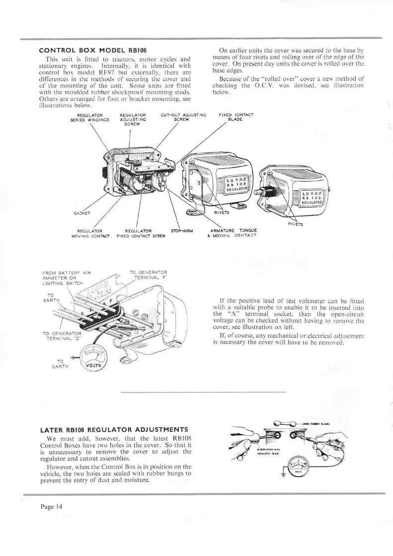
CONTROL BOX MODEL RB1O8
This unit is fitted to tractors, motor cycles andstationary engines. Internally, it is identical withcontrol box model RF97 but externally, there aredifferences in the methods of securing the cover andof the mounting of the unit. Some units are fittedwith the moulded rubber shockproof mounting studs.Others are arranged for foot or bracket mounting, seeillustrations below.
On earlier units the cover was secured to the base bymeans of four rivets and rolling over of the edge of thecover. On present day units the cover is rolled over thebase edges.
Because of the "rolled over" cover a new method ofchecking the O.C.V. was devised, see illustrationbelou'.
FIXED CONTACTBLAOE
FIEGULATOR REGULATOR CUT-OUT AAJUSIINGSERIES WINOINGS ADJUSTING SCREW
REGULATOR REGULATOR SiIOPTARMI,(OVING CONTAC? FIXED @NTACT SCREW
FROM BA-ITERYAMMETER ORLIGHTING SWITCH
TOEARTH
TO GENERATORTERMINAL,D.
LATER RB'08 REGULATOR ADJUSTMENTSWe must add, however, that the latest RBl08
Control Boxes have two holes in the cover. So that itis unnecessary to remove the cover to adjust theregulator and cutout assemblies.
However, when the Control Box is in position on thevehicle, the two holes are sealed with rubber bungs toprevent the entry of dust and moisture.
If the positive lead of test voltmeter can be fittedwith a suitable probe to enable it to be inserted intothe "A" terminal socket, then the open-circuitvoltage can be checked without having to remove thecover, see illustration on left.
If, of course, any mechanical or electrical adjustmentis necessary the cover will have to be removed.
Page 14

ADJUSTMENTS IN SERVICEThere is only a limited amount of service work
possible for the motor engineer who will usuallyrequire to work with the components in situ.
The perforn,ance of the regulator may be affectedby three factors:(1) Maladjustment of electrical setting, usually the
result of tinkering adjustments.
LRT9_ REGULATOR CONTACTS SETA word now about the Regulator Contact Sets
then.rselves. There is only this one standard set usedfor the Voltage Regulator on all the LRT9 Regulatorunits.
(2) Oxidation of the points due to nortnal usage.(3) Incorrect air gaps invariably due to interference.
These faults can usually be corrected quite easily.The voltage can be set with the aid of a good Moving
Coil Voltmeter as detailed in Part 3. The air gapscan be checked and the regulator points cleaned, as
detailed in the following paragraphs.
LRT9 _ CUT-OUT CONTACTS SETAnd here is the standard contact set for the Cut-out
ol the LRT9 unir.
'-$ffif&'--*i.ffil',',;".V LJ \#:;
ffi*ffilcffi*s
n1ffi,1* ffi&#u:e #B
*p
Note. - The "E" shims shorvn in the above photo-graph are not used on later models of the LRT9, foradjusting the contacts gap. The correct gap beingobtained by bending the fixed contact carrier uith theaid of a suitably slotted bending tool.
RB_ REGULATOR CONTACTS SETThe contact set shorvn belorv is used on tlie latest
type regulator fitted to the RF95/3. RBi07. RB108and RBl06/2.
WW-# 'wffiffiHffi
ffiffi
RB - CUT.OUT CONTACTS SETAnd this is the contact set for the cut-out of this unit.
ffiffiffiwffiffi
Page 15

THE REGULATOR VOLTAGE SETTINGAdjustment of the voltage setting is very easily
carried out by means of an adjusting screw, A, atrdlock nut, B, on earlier units. (A spring loaded screwis used on later production units).
This dangerously simple adjustment can only besafely made with the control box connected to agenerator. A good quality moving coil voltmetershould be used.
The operation as carried out in service is fullydealt with in "Testing the Charging Systeur".
The regulator settings should always be checkedbefore any interference with the contact points andalr gaps.
There are standard settings for all conditions ofworking which will be outlined later.
CLEANING OF CONTACTS
CLEANING THE CONTACTSThe contacts on the latest type ol control bor are
easily accessible, so that it is not necessary to adopiany special procedure belore cleaning them.
Earlier control boxes. for instance. the RF95. RF96,RF97 and RB106/l employed the LRT9 regulator, andit is impossible to clean the regulator contacts. untiithe contact plate is swung ontu'ards.
The fixed contact plate is secured by trvo scre\\s.These are both slackened. especially the upper screii'(that is, the one farthest from the base plate). Thecontact plate is then srvun-e outrvards.
Different materials are required lor cleaning theregulator and cutout contacts. The regulator contactsare made of tungsten. and should be cleaned uithcarborundum stone. or silicon carbide paper.
The cut-or.rt contacts are made of silver. and shouldbe cleaned with fine glass paper.
A11 dust should be removed rvith a cloth soaked inmethylated spirits.
ARMATUREFIXING SCREWS@
REGULATORFRAME
@ARMATURE
REGULATOR AtR GAPS (LRTg)As indicated in this illustration letter "A" is the
armature carrying the moving regulator point whichis mounted on the spring blade and located by twoscrews in slotted holes. Thus the armature is move-able in relation to the regulator frame (B).
The bobbin core face is shown at (C) and theregulator points at (D).
There are three important dimensions:(l) The air gap in the vertical plane between the
regulator frame and armature which should be.020". It is permissible for this gap to taper,either upwards or downwards, between the limitsof .018" and .020".
(2) The bobbin core face to the horizontal memberof the armature: which should be maintained at.012" to.020", with the gauge placed underneaththe brass pip, or shim.
(3) With the armature pressed against the regulatorframe, the contact point gap must be between.006" and .077".
FrxED CONTACT O.006 - O.Ot7 "BRACKET WITH ARMATURE
PRESSED TO CORE
oNote. - On the latest pattern of the LRT9 regulator.
adjustment of the contact gap is made by bendingthe flxed contact carrier with a suitably slottedbending tool. It will be found that shims are not nowused for varying this gap, as on the earlier models.
L RT9
RBr0612
Page 16

o. o3o'-o.oro" n9r, ARMATU REPRESSED AGAINST A\UGESCUT.OUT AIR GAP AND ELECTRICAL
SETTTNGS (LRTg)The cut-out switch seldom calls for any attention
rvhatsoever.
It should be close at 12.7 to 13.3 volts for the 12 voltrnodel and 6.J to 6. / volts on the 6 volt model andshould re-open at betu'een 8.5 and l0 vglts on ,the,l2voliEocl:l or 4.5 to 5 volts on the 6 volt model, witha reverse current reading of between 3.5 and 5 amperesin both cases.
The correct air gaps are as indicated in this illus-tration:
.014 inches.
.0ll to .015 inches.
.002 to .006 inches.
.030 to .034 inches. WITH O.O25 GAUGE
& coRE, CoNTACT
ARMATURE FXINGSCRE:WS
o.ol4" @
SCRE\YSECURING
FTXED CONTACT
BETWEEN ARM.ATURE SHIMcAP TO BE O.OO2: 0.006.
@
ABCD
should be
REGULATOR CONTACTS RESISTOR
There are three standard types of contacts resistorused on the previously mentioned regulators to protectthe contacts from damage by arcing.
ll The CARTRIDGE type on the right is nominallyf f rated at 63 ohms and is used on 12 volt regulators.Il fn" 6 volt version is nominally rated at 3-8 ohms.lt
The CARBON PELLET type on the left is generallybuilt into sealed control boxes such as we use ontractors and motor cycles.
It is mounted on the back of the regulator frarneand has a nominal resistance value of 38 ohms for 6volt sets and 63 ohms for 12 volt sets.
The WIRE WOUND type below is nominallyrated at 60 ohms for 72 volt units and 30 ohms for6 volt units. This is used on the latest RB106/2.
R8107, R8108 AND RBl05/2 CONTROL BOXES_ REGULATOR AIR GAP SETTINGS
Adjustment of the regulator is obtained by alteringthe spring tension on the blade of the contact set bymeans of the adjusting screw B and lock nut A onearlier units or by means of a spring loaded screw oncurrent units.
The air-gaps which are slightly different from theLRT9 can be re-set as follows:
Unscrew the fixed contact adjustment.Unlock armature securing screws.
Insert .021" feeler gauge between armature andcore face.
Press armature down squarely against thegauge and re-tighten armature fixing screws.
With gauge still in position, screw the flxedcontact down until it just touches the movingcontact and tighten lock nut.Reset the voltage in the normal manner.
TENSION SPRING
LOCK NUT
ARIVIATURE SECURING
FIXED CONTACTUSTMENT SCREIY
ARMATURE
CORE FACE
scREws
FOR OPEN-CIRCUITVOLTAGE SETTINGSREFER TO PART 3..CHECKING THECHARGING SYSTEM''
Page 17

R8107, RB108 AND RB105/2 CONTROL BOXES
-CUT.OUT AIR GAP AND ELECTRICALSETTINGS
It is unlikely that the cut-out switch will requireany attention or adjustment, but for general infor-mation the electrical settings are similar to those forthe LRT9 Units:
Cut-inVoltage
Drop o.ffVoltage
ReverseCurrent
12 volt models6 volt models
12.7 - 13.36.3 - 6.7
8.5 - 11.04.8 - 5.3
3.0 - 5.03.0 - 5.0
Note: By means of the bi-metal compensation device,cut-out settings remain substantially constantover a wide range of temperatures. Any smallvariations in setting due to changes in tem-perature result merely in proportionately smallincreases or decreases in the generator cutting-in speed. No temperature correction factorsneed therefore be applied to the above settings.
The gaps should be:
A : .025" - .040'with the armature pressed down.B : .015" - .020" with the armature released. Thecut-out fixed contact follow through should be between.010" - -020".
FUSESThe modern system of assembled wiring looms has
offered such protection to the main circuit wiring thatsafety fuses are not generally installed in these circuits.
The most vulnerable points will be the accessorycircuits, particularly when additional accessories arefitted.
It will have been observed that on the RF series ofcontrol boxes two accessory fuses are incorporated:one fuse generally known as the ,A.4 fuse will protectthose accessories which are directly controlled by theignition switch. The other, the A2, will provide forthe remainder of the accessories, not under themaster control of the ignition switch.
The RBl06 box has no fuses. With this box, it isconvenient to employ a separate twin fuse base for theaccessories as shown in this picture. Or, when re-quired by the car manufacturer multiple fuse boardscan be used.
The fuse base shown is the type FS6 which isnormally equipped with a 35 and a 50 amp. fuse. The35 amp. fuSe on the right will protect those itemsconnected through the ignition switch; the 50 amp.fuse on the left will serve the miscellaneous accessories
SIOP PLATE
TENSION SPRING
FIXED @NTAST
COREFACE
supplied directly from the control box terminal A1,and may include such heavy current units as WindtoneHorns.
LIVEFU SES
SPAREFUSES
Page 18

PUSH-ON COVER
SPARE FUSE
FUSE UNIT MODEL 4JF
This unit is also used in conjunction with the"Lucarised" RB106/2, when two-way connexions arerequired.
It incorporates either two 35 amp. fuses or, one35 amp. and one 50 amp. fuse, depending on theapplication.
Provision is made for connecting several l7'5 amp.connectors. A single grub-screw type terminal is alsoprovided.
FUSE UN!T MODEL 5JF
This unit incorporates the Lucar terminal bladeand is for use in conjunction with the standardRB106/2.
As standard the unit incorporates a 35 amp. fuse.It provides for connecting six 17'5 amp. connectors.
AUXILIARYTERM INAL
SPAREFUSES
Page l9

PART THREE
Checking the Charging System
SYSTEMATIC CHECKINGIt must be understood that the circuit as a whole
rvill not function correctly unless each of the individr.ralunits is in order. not forgettin-q of course the wiringbetween them.
In checking for a fault on the charging systenl.therefore, proceed according to a set plan; it is no
THE HEAVY DISCHARGE TESTThe hydrometer test gives a fairly accurate account
of the state of charge of each cell, but a furthertest must be made to make sure that the batteryrvill supply heavy currents at the required voltage, theheavy starting currents for instance. For this purpose,a "heavy discharge tester" is used which puts anelectrical load on each cell. The load, or resistance.takes at least 150 amperes from the cell in the case ofbatteries whose capacities at the 10 hour rate are below75 aH. thus reproducing conditions similar to thoseexisting when the starter motor is operated. If thehydrometer test showed the cell to be charged and if,under these test conditions, the voltage remainsconstant at approximately 1.5 to 1.6 volts, we can besure the cell is serviceable. A rapidly falling voltagereading indicates a weak cell. The drop tester shouldbe held in position for about l5 seconds per cell.
The same type of tester is used for motor cyclebatteries, but a smaller load, this time of 12 amps. isadequate. A load of 300 amps. must be used forbatteries whose capacities at the 10 hour rate is 75 aHand above.
Having made certain that the battery is serviceable.next test the source of the charging current, thegenerator.
good tackling the job haphazardly. The fault mustbe localised to a particular section, at the same timeverifying the rest ofthe charging circuit on the vehicle.
HYDROMETER TESTFirst check the specific gravity of the electrolyte in
each cell. Remember, specific gravity is affected bytemperature variation and the figures quoted in thetable below are corrected to 80oF. (26.6"C.). Specificgravity readings taken at electrolyte temperaturesother than this must be corrected before a trueindication of the state of charge, of battery under test.can be determined.
Hone trade I Climatesand climqres I frequently
Cell lordinarilyl ot'erbelot' | 80't'800F. I Q6.6'C.)
(26.6"C.)
Fullycharged .. | 1270-1290 | 1210-1230Abouthalf-charged.. I 1190-1210 | ll30-1150Completely discharged
| 1110-1130
| 1050-1070
The battery should normally be at least half-charged.
Page 20
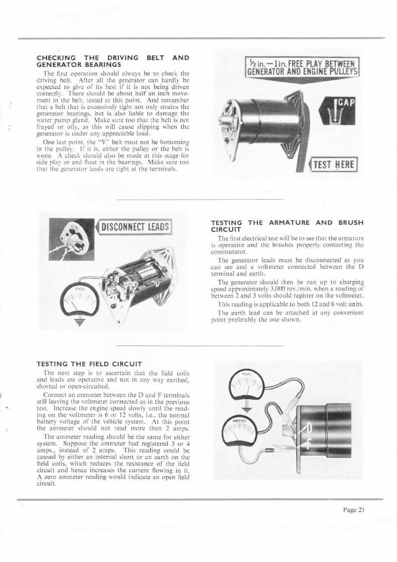
CHECKING THE DRIV!NG BELT ANDGENERATOR BEARINGS
The first operation should always be to check thedriving belt. Atter all the generator can hardly beexpected to give of its best il it is not being drivencorrectly. There should be about haif an inch move-ment in the belt. tested at this point. And remernberthat a belt that is ercessively tight not only strains thegenerator bearings. but is aiso liable to damage thelvater pump gland. Make sure too that the belt is notfrayed or oily. as this will cause slipping when tl.regenerator is under any appreciable load.
One last point. the "V" belt must not be bottomin-uin the pulley. If it is. either the pulley or the belt isworn. A check should also be made at this stage forside plal' or end float in the bearings. Make sure toothat the _senerator leads are tight at the terminals.
TESTING THE FIELD CIRCUITThe nert step is to ascertain that the field coils
and leads are operative and not in any way earthed.shorted or open-circuited.
Connect an ammeter between the D and F terminalsstill Ieaving the voltrneter connected as in the previoustest. Increase the engine speed slowly until the read-ing on the voltmeter is 6 or 12 volts, i.e., the normalbattery voltage of the vehicle system. At this pointthe ammeter should not read more than 2 amps.
The ammeter reading should be the same for eithersystem. Suppose the ammeter had registered 3 or 4amps., instead ol 2 amps. This reading could becaused by either an internal short or an earth on thefield coils, which reduces the resistance of the fieldcircuit and hence increases the current flowing in it.A zero ammeter reading would indicate an open fieldcircuit.
T[$T Xtnr
TESTING THE ARMATURE AND BRUSHCIRCUIT
The first electrical test will be to see that the armatureis operative and the brushes properly contacting thecommutator.
The generator leads must be disconnected as youcan see and a voltmeter connected between the Dterminal and earth.
The generator should then be run up to chargingspeed approximately 3,000 rev./min. when a reading ofbetween 2 and 3 volts should register on the voltmeter.
This reading is applicable to both 12 ar,d 6 volt units.
The earth lead can be attached at any convenientpoint preferably the one shown.
k: in.* lin. FRtt PLAY ilETWEIAerilrnAT0R 1il0 Eil&lll[ PuLLEYl
Page 2l
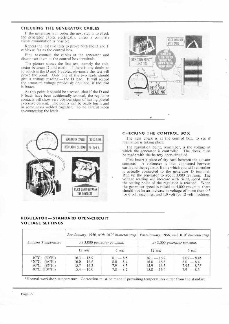
CHECKING THE GENERATOR CABLESIf the generator is in order the next step is to check
lhe generator cables electrically, unless a completevisual examination is possible.
Repeat tl,e last two tests to prove both the D and Fcables as far as the control box.
First re-connect the cables at the generator anddisconnect them at the control box terminals.
The picture shows the first test, namely the volt-yneter between D and earth. If there is any doubt asto rvhich is the D and F cables, obviously this test willprove the point. Only one of the two leads shouldgive a voltage reading - the D lead. It will recordtrhe armature voltage previously obtained, if the leadis intact.
At this point it should be stressed, that if the D andF leads have been accidentally crossed, the regulatorcontacts will show very obvious signs of having passedexcessive current. The points will be badly burnt andin some cases welded together. So be careful when:e-connecting the leads.
6Hmff$n sPfft 3C{]0R,l*.
ftt$lltAi0& $iTIlx$ r6- i6'8 Y.
REG ULATOR - STANDARD OPEN.CIRCU ITVOLTAGE SETTINGS
i{l'iix)*oei'ffif siwffi$pttt $**
,,tr, /-!
,,u-1,::-...{:S3]
CHECKING THE CONTROL BOXThe next check is at the control box. to see if
regulation is taking place.
The regulation point, remember, is the voltage atrvhich the generator is controlled. The check mustbe made with the battery open-circuited.
First insert a piece of dry card between the cut-outcontacts. A voltmeter is then connected betweenearth and the regulator frame which you will rememberis actually connected to the generator D terminal.Run up the generator to about 3,000 rev./min. Thevoltage reading will increase with rising speed, untilthe setting point of the regulator is reached. Whenthe generator speed is raised to 4,000 rev./min. thereshould not be an increase in voltage of more than 0.5for 6 volt machines. and I .0 volt for 12 volt machines.
Pre-Jarurury, 1956, v,ith .012" bi-metal strip Post-January, 1956, witlt .010" bi-metal strip
At 3,0N generator rev.f min. ll 3,000 generqtor rev.f min.
l0oc. (50oF.)*20oc. (68'F.)30oc. (860F.)40'c. (104'F.)
t6.3 - 16.916.0 - 16.615.7 - 16.315.4 - 16.0
6 volt
8.1 - 8.s8.0 - 8.47.9 - 8.37.8 - 8.2
Antbient Temperature
16.1 -16.7 I 8.05-8.4s16.0-16.6 I 8.0 -8.4r 5.9 - 16.5 I 1.95 - 8.35rs.8-16.4 I 7.9 -8.3
*Normal workshop temperature. Correction must be made if prevailing temperatures differ from the standard
Page 22

TO OPEN.CIRCUIT THE CONTROL UNIT-REMOVE "A'' AND "AI" LEADS
The foregoing method of open circuiting theregulator will provide an approximate idea of thesetting, but in order to get a true reading the followingprocedure should be adopted.
The A and A1 lead should first be removed fromthe terminals at the control box. This does twothings: it disconnects the battery from the generatorand puts the regulator load winding out of circuit.In other words, as we are only making a voltage adjust-ment, all we want in circuit is the voltage regulatorshunt (Voltage-Coil). Tll: series turns would affectthe voltage setting and must be out of circuit if anaccurate reading of the voltage setting is to be obtained.
The A and A1 leads rvill have to be twisted togetherafter detaching fron-r the control box terminals in orderto provide a feed from the battery to the ignition coilto enable the en-eine to be run.
RUN GTTIERAT(}T ATADJUSTING THE REGULATOR SETTINGS
And now that the regulator is on open-circuit, itsadjustment is very simple.
Run the generator at charging speed. 3,000 rev./min.,. with the voltmeter already connected between regulator
frame (Gen. D) and earth. Turn the regulator adjust-ing screw clockwise to increase the voltage, or anti-clockwise to lower it, Reconnect A and Al leads.Remove card from cut-out points.
Do not set the O/C voltage to exceed the maximumof the tolerbnce given in the table of settings andtemperatures.
ffi'$ *$$r"erfi*ijr{{}} #ffiffiffiffi
"q_[sguJ-I=E!g,_"g
POSSIBLE FAULTS- HIGH VOLTAGEREAD!NG
If turning the adjustrnent screw has no effectwhatsoever on the O/C voltage and the reading isright off the scale, the most likely fault is a bad controlbox earth.
There are two other less likely possibilities: anopen-circuit regulator shunt winding or a shortbetween the D and F terminals. In all three casesthere can be no regulation of the generator voltage.Regulation. you remember, depends on the shuntwinding - and one end of this is connected to thecontrol box earth terminal. Also, if the field anddynan.ro terminals are shorted at atry point, neitherthe regulator points nor the resistance can ever be incircuit to limit the generator output voltage.
p*$sf ilr'P&{itYffi'''"qe8ti:lirilldrlli!l;riu$*ili$!$ise'--'
*!'$$ {t$l*tli& ,i.$i'tilffi wte&i** $:'
. .' , '.', . '.......|i:,..1. l
RIASI
N$iInif,$t
:tt
''. *i, Se,;, #1A
v# a_ffi &tr ffi fl&{JL&T* ffi &*J U $Tffi r${y$
Page 23
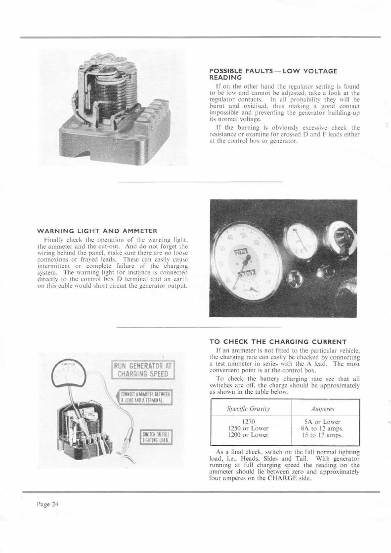
WARNING LlGHT AND AMMETERFinally check the operation of the warning light,
the ammeter and the cut-out. And do not forget thewiring behind the panel, make sure there are no looseconnexions or frayed leads. These can easily causeintermittent or complete failure of the chargingsystem. The warning light for instance is connecteddirectly to the control box D terminal and an earthon this cable would short circurt the generator output.
&ffru &€fffrx&}*R &rrM&xfi{ffm $rrx*
r8l{x[0t*M*rrI$ $mfie'&
&il$ &r&"& ff*lrfier.
POSSIBLE FAULTS - LO\^/ VOLTAGEREADING
If on the other hand the regulator setting is foundto be low and cannot be adjusted. take a look at theregulator contacts. In all probability they u,ill beburnt and oxidised, thus r-r-raking a good contactimpossible and preventing the _qenerator building-upits normal voltage.
If the burning is obviously excessive check theresistance or examine for crossed D and F leads eitherat the control box or generator.
TO CHECK THE CHARGING CURRENTIf an ammeter is not fitted to tlre particular vehicle,
the charging rate can easily be checked by connectinga test ammeter in series with the A lead. The mostconvenient point is at the control box.
To check the battery charging rate see that allswitches are off, the charge should be approximatelyas shown in the table below.
Specific Gravity Antperes
12101250 or Lower1200 or Lower
5,A' or Lower8A to 12 amps.15 to 17 amps.
As a final check, switch on the full normal lightingload, i.e., Heads, Sides and Tail. With generatorrunning at full charging speed the reading on theammeter should lie between zero and approximatelyfour amperes on the CHARGE side.
?age 24
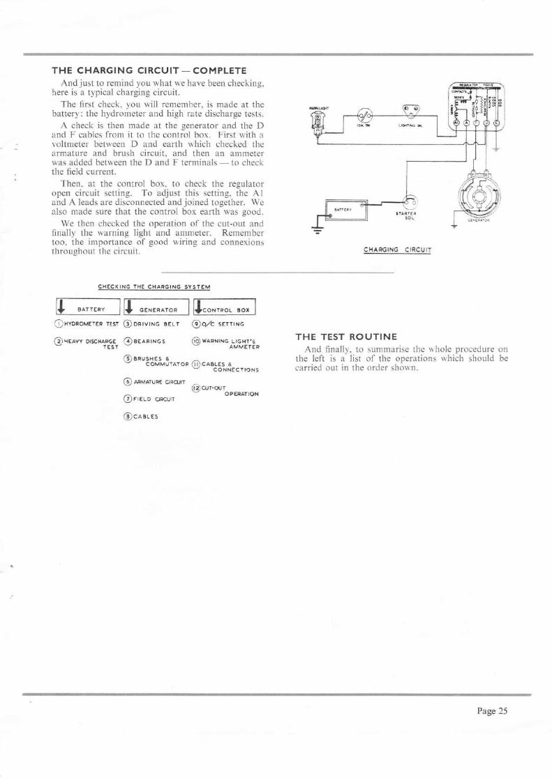
THE CHARGING CIRCUIT - COMPLETEAnd just to remind you what we have been checking,
here is a typical charging circuit.The first check, you will remember, is made at the
battery: the hydrometer and high rate discharge tests.
A check is then made at the generator and the Dand F cables from it to the control box. First with avoltmeter between D and earth which checked thearmature and brush circuit, and then an ammeterwas added between the D and F terminals - to checkthe field current.
Then, at the control box, to check the regulatoropen circuit setting. To adjust this setting, the Aland A leads are disconnected and joined together. Wealso made sure that the control box earth was good.
We then checked the operation of the cut-out andfinally the warning light and ammeter. Remembertoo, the importance of good wiring and connexionsthroughout the circuit.
CHECXING 'HE
CHAFGING SYSTEM
@o/c serrrrc
6D) wnpxrHc LtGHr,&AMMETEP on
be
@xvonoveren resr @DRrvrNG BELI
fi*(eavv orscHAFGE 6)aeanrxosrEsr -G) snusxes I ^
c oMMUrAroR (D tottStnIa. r,on,
@ mvarunt ono.lr(3)cur-our
@ rreuo onorrr - .PERATIoN
@craues
CHAPGING CIRCUIT
THE TEST ROUTINEAnd finally, to summarise the whole procedure
the left is a list of the operations rvhich shouldcarried out in the order shown.
Page 25
PART FOUR
Current-Voltage Regulators (RB 310, 6GC & R8340)
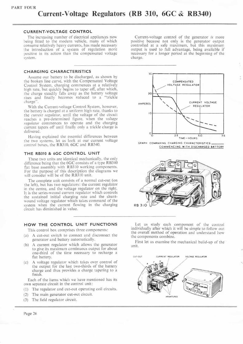
C HARGI NG CHARACTERISTICSAssume our battery to be discharged, as shown by
the broken line curve, with the Compensated VoltageControl System, charging commences at a relativelyhigh rate, but quickly begins to taper off, after which,the charge steadily falls away as the battery voltagerises and finally becomes reduced to a "tricklecharge".
With the Current-voltage Control System, however,tl-re battery is charged at a uniform high rate, thanks tothe current regulator, until the voltage of the circuitreaches a pre-determined figure, when the voltageregulatot commences to operate and the chargingcurrent tapers off until finaliy only a trickle charge isdelivered.
Having explained the essential differences betweenthe two systems, let us look at our current voltagecontrol boxes, the RB3l0, 6GC and RB340.
THE RB3IO & 5GC CONTROL UNITThese two units are identical mechanically, the only
difference being that the 6GC consists of a type R8340flat base assembly with RB310 working components.For the purpose of this description the diagrams wewill consider will be of the RB3l0 unit.
The complete unit consists of a normal cut-out (onthe left), but has two regulators: the current regulatorin the centre, and the voltage regulator on the right.It is the series-wound current regulator which controlsthe sustained initial charging rate and the shunt-wound voltage regulator which takes command of thesystem when the current flowing in the chargingcircuit has diminished in value.
CU RRENT-VOLTAGE CONTROLThe increasing number of electrical appliances now
being fitted to the modern vehicle, many of whichconsume relatively heavy currents, has made necessarythe introduction of a system of regulation morepositive in its action than the compensated voltagesystem.
HOW THE CONTROL UNIT FUNCTIONSThis control box comprises three components:
(a) A cut-out switch to connect and disconnect thegenerator and battery automatically.
(b) A current regulator which allows the generatorto give its maximum continuous output for aboutone-third of the time necessary to recharge aflat battery.
(c) A voltage regulator which takes over control ofthe output for the last two-thirds of the batterycharge and thus provides a charge tapering to afinish.
Each of the items which we have mentioned has itsown separate circuit in the control unit:(1) The regulator and cut-out operating coil circuits.
(2) The rnain generator cut-out circuit.(3) The field regulator circuit.
Current-voltage control of the generator rs morepositive because not only is the generator outputcontrolled at a safe maximum, but this maximumoutput is used to full advantage, being available ifnecessary for a longer period at the beginning of thecharge.
AMPERES
TIME- HOURS
GPAPH COMPARING CHARGING CHAFACT€RISTICS-COMMENCING WITH OISCHAPGED gATTERY
YOLTAG€ REGUUTOR
o
oLo
VOLT
rTEO
GE PEGULAIOR
CUFPEA
t* oto'T VOLTAGE
I L ATOF
\
5.O
Let us study each component of the controlindividually after which it will be simple to follow outthe overall method of operation and understand howthe components combine.
First let us examine the mechanical build-up of theunit.
%
Page 26

THE CONSTRUCTION OF THE CONTROLUNITS
The unit is built up from a metal base (1) uponwhich is fixed an insulating pad (2), mounting threeiron angled frames each with an iron core (3) onwhich will be fixed a coil winding.
The Voltage and Current Regulator Units (on rightand centre) are basically similar.
A pivot angle bracket (4) - the armature - on
which is fastened one contact point is mounted bymeans of a spring blade (5) in metallic contact with themain frame. The horizontal member of the armaturelies immediately over the bobbin core. On its verticalmember a spring blade (6) is fixed downwards andcoincides with an adjusting screw in the back of theframe. This armature is the moving member of thecontact set. The fixed contact point is screw mountedon another and smaller bracket (7) and is also fixed to,but insulated from, the top of the main frame. Bymeans of the setting and adjusting screws the pressurebetween the pair of contact points may be varied toprovide the requisite voltage and current settings ofthe regulators.
The main D (Armature) terminal of the generatorconnects to the frame of the voltage regulator (8) andthus to the moving contact point (9). The fixed point(7) is interconnected with the fixed point ofthe currentregulator (10) and the current regulator frame connectsdirectly to the F (Field) terminal of the generator.
When at rest the two pairs of contacts will be closedthus completing the circuit between the generatorarmature line and the "field". In this condition thegenerator will charge, but immediately either of thecontact pairs is opened by the magnetic pull from thecoil bobbins, the field circuit will be opened and thegenerator will cease to charge.
When in operation this becomes an alternate rapidopening and closing of the contacts at a frequency inthe order of 30 to 50 times per second, enabling a veryfine regulation of the generator field to be obtained.
The contact point assembly of the automatic cut-outswitch - left - is of general similar construction buta single opening and closing operation connects anddisconnects the generator from the battery. In thenormal position the cut-out points are open whereasboth pairs of regulator points are closed.
TEMPERATU RE COM PENSATIONThe main coils of the cut-out and voltage regulator
consist of many turns of fine copper wire and, con-sequently, the ohmic resistance of these coils rises andfalls as the temperature rises and falls - due in partto ambient working conditions and in part to thenormal passage of current. In turn, this causes theoperating current and therefore the magnetic pull onthe armature to vary inversely with changes in tem-perature. Thus, to maintain the necessarily closeoperating limits expected of these units, some form ofcompensation is required.
The method adopted with cut-outs and all voltageregulators other than 24-volt units is to utilise a bi-metal strip either to supplement or to take the place ofthe armature tension spring - the hinge spring beingof steel, copper coated in cut-outs and blue in voltageregulators. The effect of the bi-metal is to cause thespring force on the armature to reduce with rises intemperature and to increase with falls in temperature.This method also compensates for variations in batteryvoltage with temperature - a higher operating voltagebeing provided in cold weather.
With 24-volt units, it is customary to employ a wirewound series (or 'swamp') resistor in the voltageregulator shunt coil circuit to minimise the effects oftemperature fluctuation - the resistor being of higherohmic value than the coil and having a low temperaturecoefficient.
Current regulators are not compensated, the resis-tance of the operating coil being too low to varysignificantly with changes in temperature.
OPERATING WINDINGSTHE REGULATOR AND CUT.OUT
The electro-magnetic relays which operate thecut-out switch contacts (A) and the voltage regulatorcontacts (B) are energised or "excited" by coils offine enamelled wire mounted on the respective bobbinsand permanently connected across the generator maincircuit, i.e., "in shunt".
When the generator "builds" a sufficiently highvoltage the current flowing in these windings inducesa magnetic field in the cores of sufficient strength topull down the armature and close the contact points,in the case of the cut-out, and separate them in thecase of the voltage regulator.
COMPENSATION
Page 27

THE GENERATOR AND CUT.OUT CIRCUITThe current path from the generator D terminal (or
armature) is taken direct to the frame of the voltageregulator unit. From there a heavy gauge copperr',ire is taken to the current regulator and a specifiednumber of turns of the conductor wound around thecurrent regulator bobbin. The conductor is then takento the cut-out bobbin where several turns are madebefbre it connects to the n-roving cut-out point. Fromthe fired cut-out point the conductor terminates at theterminal (B) thus completing the current path fromgenerator to battery.
The turns of this series winding on the cut-outbobbin are wound in the same direction as thepreviously mentioned shunt winding and so increasethe pull, thus holding the contacts together tightly.The shunt coil closes the cut-out points at between12.1 and 13.3 volts on the 12 volt system and currentin the series winding holds them down.
When the generator ceases to charge and the voltageflalls, these points should re-open at between 9.5 and I 1.0volts. A reverse current rvill commence to flow backfrom the battery into the generator windings. Thisreverse current de-magnetises the core and immediatelyr,hrows the armature off, thus opening the contactpoints.
THE GENERATOR FIELD REGULATIONCIRCUIT
To make the generator "build" it is necessary toconnect the field coils to the generator nrain circuit,i.e., connect terminal F to D.
As sl.rown in this picture the F terminal at thegenerator is connected to the frame of the currentregulator. From the franre we pass to the rloving
contact point, lrom the flxed contact point through anumber of turns of wire on the upper part of thevoltage regulator and then to the fixed contact pointof the voltage regulator. We continue from themoving contact on the voltage regulator to its framewhich is the generator main connexion (D). Thusthe field circuit is connected through two pairs ofcontact points "in series" and if either is openedthe field circuit will be broken or "opened". Whenthis occurs a heavy destructive arc takes place at thecontact points and would quickly damage them. Toreduce this, a resistance is connected between Dand F as shown. This provides an alternative pathfor the field current, but in passing through this resis-tance however, it is considerably weakened.
The turns o[ wire shown at the top of the voltageregulator bobbin - right - form what is termed a"Frequency Coil" and simply serves to increase thevibration frequency of the armature, resulting in asteadier charging current.
It can now be seen that the action of the voltageregulator is controlled by the shunt coil and thebucking winding together.
The current regulator is entirely controlled by theheavy turns of wire which carry the total current fromthe generator.
Finally it should be observed that in the normalposition both pairs of regulator contacts are closed;that, is, the field is fully connected.
Page 28

GENERAL METHOD OF OPERATIONAssuming a flat battery in circuit.Immediately the generator is run it builds up a
voltage. When this rises to between 12.7 and 13.3 inthe case ofthe 12 volt unit the shunt coil ofthe cut-outis sufficiently energised to close the cut-out points (A)against the pressure of the adjusting spring.
Current will then flow to the battery and increasedirectly with generator speed. By the time thegenerator output reaches the permissible uaximurn,the current regulator coil (B) is sufficiently energisedto pull down the current regulator armature againstits spring setting and so open tl,e contact points.breaking the field circuit. The generator voltage thendrops, the exciting current in the coil u'eakens and theregulator points close again allou'in,s the voltage torebuild. This opening and closing cycle continues atbetween 30 and 50 operations per second. thr"rs limitingthe total generaror output to a safe marimum.
By the time the battery is sornethin-u over one-thirdfully charged its terminal voltage rr'ill l-rave risen,resulting in a general rise in the line voitaqe, i.e..between generator and battery. When the linevoltage reaches the correct value the voltage regulatorcoil (C) is sufficiently energised to pttll down itsarmature against the spring setting. This set offield contacts will open and ther.r be put into a state ofvibration which will reduce and limit the generatorvoltage. As the battery, and consequently the linevoltage, continues to rise, the field point vibration rvill
increase in amplitude and keep the generator voltageat a sale maximum.
In this condition the difference between generatorand battery voltage continues to become less and thecurrent from the generator is finally reduced to tricklecharge proportions.
Frorn the moment that the voltage regulator pointscome into operation, the current from the generator isso reduced that the current regulator will no longeroperate, and its contact points will remain closed.
In practice. a changeover period often exists whenboth regulators are in operation.
THE FREAUENCY COILThe frequency coil (sometimes referred to as a
btrcking coil), as you can see in the illustration, iswound in series with the two sets of contacts in thefleld circuit. It thus passes field current. The windingconsists of a few turns of thick copper wire, so woundas to assist the shunt coil of the voltage regulator.In increasing the ampere-turns of the bobbin, ittherefore influences the operation of the voltageregulator contacts, quickening the break and increasingthe frequency of vibration. This serves to stabilise theoperation as a whole, smoothing out and steadyingthe generator output.
Page 29
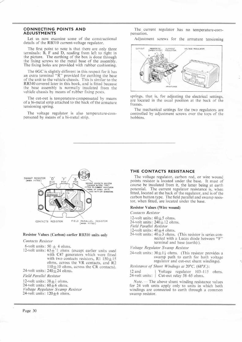
CONNECTING POINTS ANDADJUSTMENTS
Let us now examine some of the constructionaldetails of the RB310 current-voltage regulator.
The first point to note is that there are only threeterminals: B, F and D, reading from left to right inthe picture. The earthing of the box is done throughthe fixing screws to the metal base of the assembly.The fixing holes are provided with rubber cushioning.
The 6GC is slightly different in this respect for it hasan extra terminal "R" provided for earthin_e the baseof the unit to the vehicle chassis. This is similar to theRB340 covered later in this book, and is fitted becausethe base assembly is normally insulated lrom thevehicle chassis by means of rubber fixing posts.
The cut-out is temperature-compensated by meansof a bi-metal strip attached to the back of the armaturetensioning spring.
The voltage regulator is also temperature-com-pensated by means of a bi-metal strip.
SWAMP RESISTOR(WHEN FrrrED)
sEcoND coNT cts R6tm(qFrcN NiDN npE)
FITTEO rc @M AEGUUDh
The current regulator haspensation.
Adjustment screws for the
no temperature-com-
armature tensioning
coNrA.rs RESrsroR r,.ro 1",,ill!."1!" 1.,
Resistor Values (Carbon) earlier RB3l0 units only
Contacts Resistor6-volt units: 50 ;[ 4 ohms.
l2-volt units: 63*'3 ohms (except earlier units usedwith C47 generators which were fittedwith two contacts resistors, Rl 150+15ohms, across the VR contacts. and R2110+10 ohms, across the CR contacts).
24-volt units: 240124 ohms.Field Parallel Resistorl2-volt units: 3813 ohms.24-volt units: 60=E6 ohms.Voltage Regulator Sv:amp Resistor24-volt units: 120t6 ohms.
springs, that is, for adjusting the electrical settings,are located in the usual position at the back of theframes.
The mechanical settings for the two regulators arecontrolled by adjustment screws over the tops of thebobbins.
THE CONTACTS RESISTANCEThe voltage regulator, carbon rod, or wire wound
points resistor is located under the base. It must ofcourse be insulated from it, the latter being at earthpotential. The current regulator resistance is, whenfitted, located at the back ofthe regulator, and is ofthecarbon button type. The field parallel and swamp resis-tor, when fltted, are located under the base.
Resistor Yalues (Wire wound)
Contacts Resistorl2-volt units: 60{5 ohms.24-volt units : 240:t 12 ohms.Field Parallel Resistorl2-volt units: 40:t4 ohms.24-volt units: 40=t3 ohms. (This resistor is series con-
nected with a Lucas diode between "F"terminal and base (earth) ).
Voltage Regulator Swamp Resistor
24-volt units: 30+1t ohms. (This resistor provides aswamp path to earth for both voltageregulator and cut-out shunt windings).
Resistance qf' Shunt Windings ctt 20oC. (68'f.):12 and \ Voltage regulator 103-l I 5 ohms.24-volt units: / Cut-out relay 58-65 ohms.
Note. - The above shunt winding resistance valuesfor 24 volt units apply only to units in which bothwindings are connected to earth through a commonswamp resistor.
FWE OF EARLY UNIEusEo w[H a7 eN&B
Page 30

LUCARTSED VERSION (RB3t0)The later pattern RB3 l0 incorporates Lucar terminal
blades, spring-loaded adjustment screws and, inaddition, a different method of cover fixing. The "ear-fixed" cover as it is called allows for shorter throughfixing screws, without an insulating tube, to be usedfor fastening the cover in position. Also, the screwscan be positioned more easily as the threaded holewhich was originally drilled within the base of the unitis now positioned externally to line up with the "ears"on the cover.
B Two 35 amp. blades.
F One 17.5 amp. blade.
D One 35 amp. blade and one 17.5 amp. blacle.
CU RRENT AOJ USTMENT ScRE*
CUT-OUTRELAY
CUT.IN AOJ USTMENT SCREW
VOLIAGE ADJU'IMElI SCRET'
CU RRENTREGULATOF
CH ECKING THE CURRENT VOLTAGECO NTROL REGULATORS
To check or adjust these units it is essential that agood quality moving coil voltmeter and ammetershould be available. It is also very necessary to seethat these instruments are maintained in an accuratestate.
Within our experience an extremely simple test setwhich may be made up, or purchased, as-illustratedhas been found the most satisfactory arrangement foruse in the service garage.
In this set a 3\" Scale Moving Coil Ammetercalibrated 5-0-50 amperes and a similar voltmetercalibrated 0-40 volts have the correct size of vervflexible leads and clips permanently connected readyfor use, the assembly being accommodated in a sheeisteel box with detachable cover, thus safeguarding theinstruments against accidental damage in service.-
Without suitable instruments NO adjustments tothese control boxes should be attempted.
In every case before interfering with the controlunit preliminary checks on the battery, batteryconnexions,. generator and generator driving beli,together with an inspection of the generator andcontrol unit cables should be made. If these arein order proceed to test, firstly the voltage regulatorand secondly, the current regulator as outlined.
fd
g
#
fI
ffilSW;-- t''w
Page 3l

TO CHECK AND ADJUST THE REGULATORopEN-crRculT voLTAGE (RB310 & 6GC)
We commence our adjustn.relrts at the voltageregulator. First disconnect the lead from the controlbox terminal "B" (marked "A" on earlier models) andconnect the voltmeter between "D" terminal (generatorarmature) and earth. Then raise the generator speedslowly to approximately 3,000 rev./min. (for C39PV,C39PVR, C39Q, C40lt, C40L, C45PV, D5LF, GL45,G524G,5A and GH45), 1,500 rev./min. (for C47. C48and D5L), 2,000 rev.imin. (for G5 12). The voltageshould rise and steady itself with a slight flick. Accord-ing to the temperature this reading should be as out-lined in the table for voltage regulator electrical settings.
If any adjustment is required do not increase thespeed above 3,000 rev./min. Unlock the adjustmentscrew on the back plate of the bracket and screw in-wards to increase the voltage, and outwards to lowerthe voltage, when corrected relock the adjustmentscrew and reduce the speed to "idling".
a.'",--'---a,
VOLTAGE REGULATOR ELECTRICAL SETTINGSThe Standard Open Circuit Voltage Settings with the generator running at approx. 3000 rev/min (1500 rev/min C47
and C48), are as follows:
Ambient Tentperature 12 volt
volts15.1 - 15.714.9 - 15.514.7 - 15.314.5 - 15.1
6 volt 24 volt
Cold Climate 10oC. (50'F.)Temperate Climate 20oC. (68'F.)Hot Climate 30oC. (86'F.)Equatorial Climate 40'C. (104'F.)
volts8.r -8.58.0 - 8.47.9 - 8.37.8 - 8.2
volts28.2 - 28.728.0 - 28.527.8 - 28.327.6 - 28.1
7.0 - 7.3 volts at 68'F. (20'C.) for 6 volt regulators for "HOLDEN"14.2- 14.8 volts at 68oF. (20'C.) for regulators used with Rootes "EASIDRIVE" units (C45PV/6)
Setting or adjusting must be done as quickly as possible in order to preclude heating effects which would introduceerrors into the setting.
wrien the generator speed is '1'd'.! Jlri;t"lroui'#irt3'r:TiT#ifl&:ili:?
above:
8.9 volts at 68oF. (20oC.) for 6 volt regulator31.0 volts at 68oF. (20'C.) for 24 volt regulator
?age 32

THE CUT-OUT SETTINGSThe cut-out should be adjusted next, for unless the
cut-out points close properly, it is impossible to adjustthe current regulator.
Leaving the voltmeter connected as in previous test,insert an ammeter between terminal "B" and the "B"cable. Switch on an electrical load, such as headlamps,and slowly increase generator speed from zero. Closureof the contacts, indicated by a slight drop in the volt-meter reading should occur between the followingfigures:
Cut-inVoltage
Drop-olfVoltage
l2 volts6,.
24
volts voltst2.7-13.3 i 9.5-11.06.3 - 6.7 4.8 - 5.s
26.s-21.0 i rs.o-23.0
The cut-out is adjusted by means of the screrv at theback. This is screrved inuards. That is to say clock-wise, to increase the voltage. and out$ards (or anti-clockwise) to reduce it.
TO CHECK AND ADJUST THE CURRENTREGULATOR
Finally the current regulator is adjusted. The volt-age regulator contacts are short-circuited by means of acrocodile clip placed across the contact plate to theframe of the voltage regulator as shown. With thebattery still disconnected from the "B" terminal, thetest ammeter is again connected between the lead andthe terminal, and again the complete load is switchedon. The generator is then run to charging speedapproximately 4,500 rev./min. (4,000 rev./min. forc48).
The current settings, for the standard generators,are as follows:
1.l-?
The drop-offvoltage can be checked by disconnectingthe lead from control box "B" terminal and connectingthe voltmeter between this and earth.
_ Run the engine up to 3,000 rev./min., then slowlydecelerate, noting the instant when the voltmeter dropsto zero. This should occur between the limits given inthe table.
Generator Voltage I Serting
volts I amps.PY_2 t2 I l9+l
39P-2 . 12 I l0+++12 I r0+++t2 I zz+t
C4OAC4o-16iFan).: ::C40-l (4t" Fan)C4OALC4OLc40LQc42c42 (EASTDRTVE)C45PV-5C45PV-6c45PV-6 (EASTDRTVE)C45PVS_6c47c48
t2 I 20+lt2 | 10+++t2 I 2s+tt2 | 2s+112 | 30+r+t2 | :s+rit2 I zz+r't2 | 2s+l12 I 30+1+12 I 2s+112 I 30+1+t2 l 3s+3
The current setting is then checked against thelgures given in the table for the appropriate generatorfitted to the vehicle.
The output is then regulated by means of the screwin the backplate. Once again, the setting is increasedby screwing inwards (or clockwise), and reduced byturning it outwards (or anti-clockwise).
Note.-Do not switch lights on after starting theengine otherwise the bulbs may burn out.
Page 33

MECHANICAL SETTINGS FOR RB31O & 6GCAdjustment of Air Gap SettingsGauge Thicknesses
Air gap settings are accurately adjusted duringassembly and should require no further attention.If, however, an armature is removed for any reason,care must be taken to obtain the correct setting onre-assembly. When setting an armature-to-bobbincore air gap, the correct size of gauge required isdetermined by the thickness of the non-magneticseparation used in the gap and also, in the case ofvoltage regulators, on the thickness of the bi-metalspring located behind the tensioning spring of thearmature.
The above variable features are easy to identifyand are as follows:0.015" separation is by means of a disc of copper.*0.009" separation is by means of a square of copper.O.Ol2" bi-metal springs are bright and unplated.0.010" bi-metal springs are copper plated.xAlternatively, two parallel copper wires were used insome units during 195617.
A flat steel gauge of 0.015", 0.018" or 0.021" is usedas follows:
Voltage Regulators:Use a 0.015" gauge for units fitted with a 0.015"disc of copper* and a bi-metal spring of either0.010" or 0.012" thickness.Use a 0.018" gauge for units fitted with a 0.009"square of copper and a bi-metal spring of 0.012"thickness.
TENS IONSPR ING
CURRENT MENT SCREY
AND LOCKING NUT
ALTERNATIVE COPPERSEPARATION ONBOBBIN CORE
SEPARATIBOBB IN
@DDlsc(c)
BI- METALBRTGHT uNPLAreo (A)oR coPPER pr-rreo (B)
ffi\ A+c ----- o.ors"\
rypE oF B1-METAL I a+c --- -.o.ors] [AND-5,EpARAT1qN I A+D ----. o o18' (
/ B+D-----o02r-,,
IXED CONTACTADJUSTMENT
SCREIV
BOBBIN CORE
VOLTAGEAND
ARMATUREASSEM B LY
(nean vrail)
ARMATURESECURI NG
TENSION
ASSEM BLYSCREW.C,
SPRING
ADJLi.STMENT SCREWLOCKING NUT
ON ONCORE
@SQUARE
(D)
@SQUARE
VOLTAGE REGUI-ATOR
Use a 0.021" gauge for units fitted with a 0.009"square of copper and a bi-metal spring of 0.010"thickness.
Current Regulators:Use a 0.015" gauge for units fitted with a 0.015"disc of copper.*Use a 0.018" gauge for units fitted with a 0.009"square of copper.
Voltage and Current Regulator Mechanical SettingsSlacken the two armature assembly securing screws
so that the armature is loosely attached to the regulatorframe.
Slacken the fixed contact locking nut and unscrewthe fixed contact adjustment screw until it is wellclear of the armature moving contact.
Slacken the voltage (or current) adjustment screwlocking nut and unscrew the adjustment screw untilit is well clear of the armature tension spring.
Using a flat steel gauge of appropriate thickness(see above) and wide enough to cover the bobbin core,insert the gauge between the underside of the armatureand the copper discx or square. Take care not toturn up or damage the edge of the disc* or square.
Press the armature down squarely against the gaugeand re-tighten the two armature assembly securingscrews. With the gauge still in position, screw in thefixed contact adjustment screw until it touches thearmature moving contact. Re-tighten the locking nut.
Carry out the electrical settings.
ARMATURE
DISCSQUARE
GAUGE
sllE I /o.ors" I --i _.--+o'or8" /--t-;==='tffi
frrEil
Drsc
Page 34
CURRENT REGULATOR

CUT.OUT RELAY MECHANICAL SETTINGSSlacken the two armature assembly securing screws
so that the armature is loosely attached to the cut-outframe. Slacken the adjustment screw locking nut andunscrew the adjustment screw until it is wel-l clear ofthe armature tension spring.
Press the armature down squarely against the coreface (copper sprayed in earlier units or fitted with asquare of copper in later units), and re-tighten the twoarmature assembly securing screws. No gauge isnecessary.
Press the armature down against the core face andadjust the armature back stop so that a 0.018" gap isobtained between the tip of the back stop and thecontact blade.
Insert a 0.010" thick flat steel gauge between theunderside of the armature and the copper separation.The gauge should be inserted from the side of the corenearest the fixed contact post. The leading edge ofthe gauge should not be inserted beyond the centreline of the core face. Press the armature down againstthe gauge and check the cut-out contacts. Theseshould be just touching.
If necessary, adjust the height of the fixed contactby carefully straightening or bowing the legs of thefixed contact post.
Carry out the electrical setting.Note. - The second setting air gap can be set at
.015" to decrease the contact follow through. Thesesettings are nominal and may later require modifyingwithin the limits 0.010" - 0.020' to obtain the correctdrop off voltage.
AD.JUSTMENT SCREWAND LOCKING NUT
CONTACTSJUST TOUCHING
FI RSTSETTI NG
SECONDSETT I NG
SETTING THE CURRENT REGULATOR ONTHE BENCH
When setting the current regulator away from thevehicle, a test generator and an artificial load is needed.The load circuit should comprise a 5l ampere-hourbattery, a 0 - 40 ammeter and rheostat capable ofcarrying up to 45 amperes without overheating. Theconnexions are shown in the illustration on the left.The control box, it will be noted, is shown with itsterminals pointing vertically upwards. This is theposition in which electrical settings are made duringproduction and is the mounting position recommendedto vehicle manufacturers. However, since settings canbe affected by change of position, bench settings shouldbe made with the control box mounted as on thevehicle. Adjust the rheostat until ammeter Al indicatesa current slightly in excess of the maximum ratedoutput of the generator normally controlled by theregulator. Run the test generator at approximately4,500 rev./min. and adjust the current regulator untilthe required setting is indicated by ammeter 42.
The permissible tolerances on current regulatorsettings are * I ampere for generators of up to ?5amperes maximum output and :E 1] amperes forgenerators of up to 35 amperes maximum output.
ARMATUREASSEM BLYSECU R I NG
SCREIYS
FRAME
ARMATURETENSIONSPRI NG
BACK STOP
CONTACT BLADE
CORE
F IXEDCONTACT
POSTADJUST HEIGHT BY
STRAIGHTENING ORBOWING LEGS
U
o.ol8
CLIP TO SHORICIRCUIT V R
AMM ETER
iA2
Page 35

THE RB34O CONTROL UNIT _ GENERALDESCRIPTION
The model RB340 control box rvill eventually super-sede the model R83l0. Whilst the electrical functionsof the RB340 are the same as the RB3l0 and 6GC,the mechanical arrangement of its regulators, and cut-out unit is different.
Also, the base which was previously a box typepressing now consists of a simple flat plate to which theresistors and Lucar connectors are riveted (see illus-tration). The contacts, which on the RB310 and 6GCare positioned above the bobbin-cores, are, on theRB340, situated parallel to the rear limb of their magnetframes. The cut-out, voltage and current regulatortensioning springs are riveted to the upper limb of thearmature. Another notable feature of the assemblyare the toothed adjustment cams carried on the frontlimb of each frame. With the aid of a special toolelectrical adjustments are made by turning the cams tovary the spring tension acting on the associatedarmature, except for the cut-out drop-offvoltage, whichis effected by bending the fixed contact bracket.
TTMPTRATUREC(}MPENSATlof'J
RESISTORSAs in the RB3l0 and 6GC, the resistors are posi-
tioned beneath the base. Contacts resistors and swampresistors are fltted to all units but an additional resistor,the field parallel resistor, is fitted to units controllingC48 generators.
Resistor Values (Wire wound)Contacts Resistor Identifl-
Resistance cationin ohms colour
As fitted in units controllingl2-volt generators having 4johm field windings: 37-43As fitted in units controllingl2-volt generators having 6ohm field windings:As fitted in units controllinggenerator model C48:
The main service feature is the simplicity of makingmechanical and electrical adjustments. Simplearmature-to-bobbin-core air gap settings are the onlymechanical adjustments to be made. The threearmatures are riveted to the rear limb of U-shapedmagnet frames thus their back air gap is fixed and non-adjustable.
TEMPERATU RE COMPENSATIO NAs in the case of the RB3l0 and 6GC, the voltage
regulator and the cut-out of the RB340 are temperaturecompensated, by means of bi-metal strips. But, inaddition, tlie RB340 has a double swamp resistor. con-nected in series with the two shunt coils.
The resistor has a higher resistance than the twoshunt coils, and it is made of an alloy, which is notaffected by changes in temperature. Thus, for allpractical purposes, the resistance ofthe shunt windings,and the resistor will remain constant, although thereare considerable changes in temperature.
SWAMP RESISTOR CONTACTS RESISTOR
FIELD PARALLEI.RESISTOR
(wHEN FrrrED)
'F' 'Wrl 'D' 'L'
Note. - Coloured paintsvalues of these resistors arefibreglass cores.
55-65
75-85
Yellow
Red
Violet
Page 36
used for indicating ohmrcapplied to one end of the
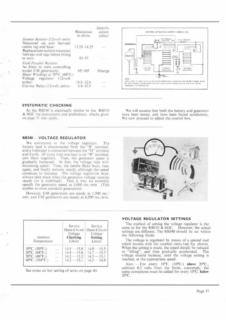
Identifi-Resistance cationin ohms colour
Sw'amp Resistor (12-volt units)Measured on unit betrveencentre tag and base: 13.25-14.25R eplacement resistor measuredbetween end ta_es before fittingto unit: 53-57Field Paraliel ResistorAs fitted in units controllingmodel C48 generators: 95-105 OrangeSlunt Winditzgs ot 20oC. (68',F.)Voltage regulator ( l2-volt !.el!:
UNT|L EARLY rN 1962, THE Vn. I *. MAGNET F&MEs WEFE LTNXEO 6y A CONN€CIOn THpMH Warca(ril rHE coNi€rs cuoseo eosrror)rre FrELD oRRrNr pAssEo. vr^ rHa c.o, r qn. saRrasttNotNcst lo TERMTNAL'D:
r$ff},
€l'"-.?"tr{
units):Cut-out Relal (12-volt r.rnits):
r0.8-12.08.8- r 0.5
SYSTEMATIC CHECKINGAs the R8340 is electrically similar to the R83l0
& 6GC the instruntents and preliminary checks givenon page 3l also applr'.
RB34O - VOLTAGE REGULATORWe comnrence at the voltage regulator. The
battery lead is disconnected front the "B" terminal.and a voltn.reter is connected bettveen the "D" terminaland Earth. (ll nrore than one lead is on "B" terrninal.join thenr together). Then. the -qenerator speed isgradually increased. At first, tl.re volta_ue rises rvithincreasing speed. Then. the needle flicks back, risesagain, and finall,r, remains steady, although the speedcontinues to increase. The voltage regulation mustalwavs take place uhen the generator voltage relnainssteady (or is stabilised). That is u,hy u,e normalll,specify the generator speed as 3,000 rev./min. (Thisapplies to most standard _qenerators).
Houever. C48 generators are steady at 1,500 rev./min. and C42 generators are steady at 4,500 rev./min.
We will assume that both the battery and generatorhave been tested, and have been found satisflactory.['e now proceed to adjust the control box.
VOLTAGE REGULATOR SETTINGSThe niethod of setting the voltage regulator is the
same as for the RB3l0 & 6GC. However, the actualsettings are different. The RB340 should be set withinthe follorving limits.
The voltage is regulated by nieans of a special toolwhich locates with the toothed cams (see fig. above).When the setting is made, the speed should be reducedto "idling", and therr gradually accelerated. Thevoltage should increase, until the voltage setting isreached, at the appropriate speed.
Note. - For every l8oF. (10'C.) aboye 20oC.,subtract 0.2 volts from the lin-rits, conversely, thesame corrections must be added for every 10"C. below200c.
AmbientTemperature
10"c. (50'F.)20oc. (68oF.)30"c. (86"F.)40oc. (104oF.) ..
ServiceOpen-Circuit
VoltugeChecking
I-imits
14.5 - 15.8t4.4 - 15.614.3 - 15.3t4.2 - 15.1
Serr:iceOpen-Cirait
VoltageSettingLirttits
14.9 - 15.514.1 - t5.314.5 - 15.114.3 - 14.9
See notes on hot setting of units on page 40.
Page 37
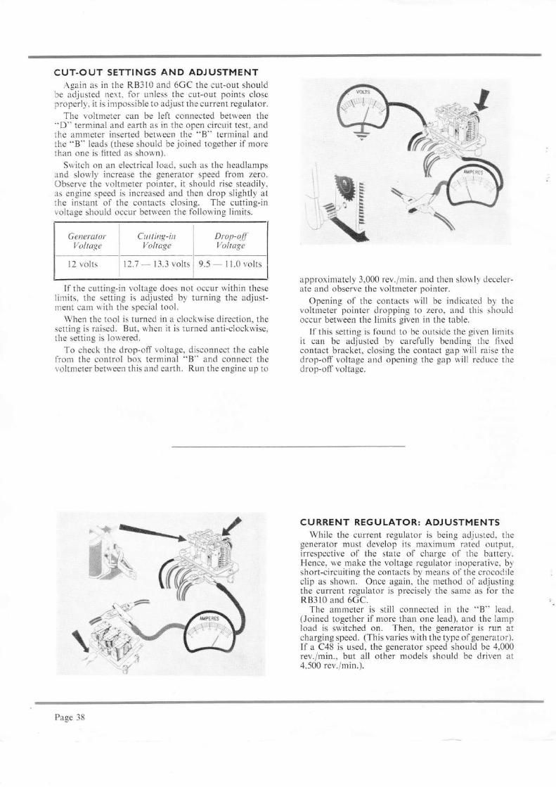
CUT.OUT SETTINGS AND ADJUSTMENTAgain as in the RB3l0 and 6GC the cut-out should
be adjusted nert. for unless the cut-out points closeproperly, it is impossible to adjust the current regulator.
The voltmeter can be left connected between the"D" terrninal and earth as in the open circuit test, andthe ammeter inserted between the "8" terminal andtire "B" leads (these should be joined together if morethan one is fitted as shown).
Switch on an electrical load, such as the headlampsand slowly increase the generator speed from zero.Observe the voltmeter pointer, it should rise steadily,as engine speed is increased and then drop slightly atthe instant of the contacts closing. The cutting-involta-qe should occur between the following limits.
If tl,e cutting-in voltage does not occur within theselimits, the setting is adjusted by turning the adjust-ment cam with the special tool.
When the tool is turned in a clockwise direction, thesetting is raised. But, when it is turned anti-clockwise,the setting is lowered.
To check the drop-off voltage, disconnect the cablefrom the control box terminal "B" and connect thevoltmeter between this and earth. Run the engine up to
\--
approximately 3,000 rev./min. and then slowly deceler-ate and observe the voltmeter pointer.
Opening of the contacts will be indicated by thevoltmeter pointer dropping to zero, and this slrouldoccur between the limits given in the table.
If this setting is found to be outside the given limitsit can be adjusted by carefully bending the fixedcontact bracket, closing the contact gap will raise thedrop-off voltage and opening the gap will reduce thedrop-off voltage.
CURRENT REGULATOR: ADJ USTMENTSWhile the current regulator is being adjusted. the
generator must develop its maximum rated output,irrespective of the state of charge of the battery.Hence, we make the voltage regulator inoperative, byshort-circuiting the contacts by means of the crocod.ileclip as shown. Once again, the method of adjustingthe current regulator is precisely the same as for theRB310 and 6GC.
The ammeter is still connected in the "B" lead.(Joined together if more than one lead), and the lampload is switched on. Then, the generator is run atcharging speed. (This varies with the type of generator).If a C48 is used, the generator speed should be 4,000rev./min., but all other models should be driven at4,500 rev./min.).
\'*
GeneratorVoltage
l2 volts
Cutting-inVoltage
13.3 volts
Drop-o.fJVoltage
9.5-ll.0volts
Page 38

CURRENT REGULATOR SETT!NGSThe current regulators should be set to the following
values with the generator running at 4,500 rev./min.(4,000 rev./min. for C48).
Unsteady readings are probably due to dirtymechanical settings.
lf, however, the reading is steady, but is higher orlower than the maximum rated output of the genera-tor, the regulator setting must be altered, by turningthe adjustment cam, with the special tool.
When, for instance, the tool is turned in a clockwisedirection, the setting is raised. On the other hand,the setting is lowered, when the tool is turned anti-clockwise.
Generalor Voltage Setting
C39PY.2c3sP-2 ::C4OAC40-l (5" Fan) ..C40-l (4j" Fan)C4OALC4OLc40LQC40TC4OTc42c42 (EASTDRIVE)C45PV_5C45PV_6c4sPv-6 (EASTDRTVE)C45PVS_6c47c48
voltst21212121212121212t2t212t212t2t2t2t2
amps.19+ Il0+++l02L+i22Ll20+l10++i)s-L?{-!18+)) -)-
30* l135+t+22+.125+l30+ t+25+l30+ l+15-L I
underneath the armature. Particular care must betaken to avoid damaging the copper shim).
While the gauge is kept in position, you shouldpress down the armature, and screw in the adjustablecontact, until it just touches the armature movingcontact. The locking-nut is then retightened, and thegauge is withdrawn.
MECHAN ICAL SETTI NGS: I NTRODUCTIONWe have told you how the RB340 control box is
checked and regulated, while it is still in position on thevehicle. However, during the course of the tests, youmay have obtained fluctuating readings on the ammeter
CLEANING THE CONTACTSWe will first consider oxidised contacts. This is a
condition, which arises normally in service. Hence, allcontacts should be cleaned periodically. Differentmaterials are required for cleaning the regulator andcut-out contacts. The contacts for the voltage andcurrent regulators are made oftungsten, and so shouldbe cleaned rn'ith fine carborundum stone or siliconcarbide paper. The dust and foreign matter should be
or voltmeter.In general, fluctuating readings are due to three
factors:-(i) Oxidation of contacts.(ii) Foreign matter in air-gaps.(iii) Incorrect air-gap settings.
wiped away by means of a fluffiess cloth, which hasbeen moistened with methylated spirits (de-naturedalcohol).
The cut-out contacts are made of silver, and shouldbe cleaned with a piece of fine glass paper. All dustshould be removed with a cloth soaked in methylatedspirits. On no account should carborundum stone oremery paper be used for cleaning the cut-out contacts,or the silver contacts will be damaged.
CURRENT AND VOLTAGE REGULATORS:AIR-GAP SETTTNGS (EARLIER UNTTS)
We will now consider how the air-gaps of theRB340 Current Voltage Control Box are set.
Once again we must remind you that the air-gapsand the fixed contact setting have been accurately setduring production. However, if the settings have beendisturbed in any way, they must be carefully reset.
Let us first describe the method for adjusting theregulator air-gaps.
As we have already stated, the RB340 has toothedadjustment cams, instead of the adjusting screws onother control boxes. A special tool is, therefore,needed, and the cams are turned as far as possible inan anti-clockwise direction. (That is, to the pointgiving minimum lift to the armature tensioning spring).
The adjustable contact is then screwed back, and agauge of .045" is inserted between the armature andthe copper separation on the core face. (The gaugemust be inserted, so that it reaches the two riyets
AIR GAP SETTINGo 5'!O.O4g-
CONTACT ADJUSTMENT
Page 39

REVISED AIR.GAP SETTINGS FOR LATERUNITS
Later units manufactured since Decernber, 1963 donot have the copper separation in the top gap of thevoltage and current regulator. Therefore, when setting.the air-gaps of these units, a thicker -eauge must be
CUT.OUT AIR.GAP SETTINGSFinally, we will describe how to set tl,e air-gaps of
the RB340 Cut-out.The armature is pressed down on the copper
separation on the core face. Then, the fixed contactbracket is set so that the "fo11ow-through" (or bladedeflection) of the moving contact is within the lirnits.010" - .035", and the armature backstop is adjusted,until the air-gap betrveen the armature and core is.035' - .045".
HOT SETTING OF UNITS DURINGMANUFACTURE
During manulacture control boxes are heat-soakedat 70oC. ( I 58'F.) before electrical settings of thevoltage regulators are made. Then, while at thistemperature, the voltage regulators are set to operateat a comparatively low voltage (14. l+0.3 volts, for12 volt units). This method, known as "l.rot-setting",ensures tl-rat accurate and stable settings obtain atnormal working temperatLrres.
On cooling to 20oC. (68"F.) tl-re ten-rperature com-pensation device causes units to regulate at highervoltages and between slightly rvider lirnits (15.0j0.6volts, for l2 volt units). Before units are despatched,"cold" checks are carried out at this lower temperatureto see that open circuit voltage performances fallbetween these wider linrits. lt follows, therefore, thatthese wider, "cold checkin-e", lirnits are the correctfigures to use when checking factory-set units in service.Figures for service setting, l.torvever, must be to closerlimits to ensure that ad.iustments carried out at lowertemperatures shall result in correct regulation at highertemperatures.
CONCLUSIONHaving obtained a pretty fair idea of the various
forrns of generator control units and tlieir working itmay be desirable to add a note ol caution.
The successful servicing of these in.rportant com-ponents does not rest entirely upon an adjustmenthere arrd there. The success of any of the servicingoperations outlinecl depencls entirely on having nrade
used to allou, for the space fonlerly occupied bycopper, the total gap measurement being unchanged.To do this, the gauge thickness of 0.045" previouslygiven nTust be increased by .007" to 0.052".
MOVING(rollow
CONTACTTHROUGH
o oto"-o 035')
---=K-- J$.9-' I-E
ARMATURE-TO-BOBBIN CORE(o.oas'o.o45')
GAPIr
(J
FJo
F)u-z
SERVICE SETTINGLIMITS
SERVICE CHECKINGLiMITS FOR
.HOT.SET
UNITS
ro 20 30
AMBIENT TEMPERATURE (..)Voltage regulator setting limits shown graphically,
including checking limits of units set at700c. ( I 580F.)
an adjr.rstn.rent which is stable and permanent in itssubseqrrent working. For this reason only a lirrritedanlcunt ol work can be successfully executed in thegeneral garage. If the control unit, for example, willnot respond to the adjustments outlined an exchangeshould be made and the original unit suhjected tobench examination in a properly equipped electricalu orkshop.
B
Pa*ee 40


![f,f]il[ Ë=ffi ffi](https://img.pdfslide.net/doc/110x75/5875e8641a28ab457b8ba96e/ffil-effi-ffi.jpg)