Embed Size (px)
Citation preview
Fine Homebuilding Cottage Shed Plans
1

Designed with a cottage look, this small shed has clapboard siding on the front, a double door, a ramp to allow access for motorized yard equipment, a window to provide light, and a flower box for decoration.
Front Elevation
Double doors constructed of 3/8-in. panel siding with 1x4 pine trim screwed from the back
Barn-style hinges and handles purchased at the local hardware store
Ramp constructed of pressure-treated framing with a synthetic-decking surface
PVC trim for low maintenance (primed pine will work as well)
Fiber-cement siding for durability and affordability
Asphalt shingles to match the house
Flower box built from PVC trim scraps
Shed Exterior Details
Copyright © 2009 The Taunton Press, Inc. Page 1

Side ElevationsThe two gable-end walls look nearly identical with white-cedar shingles, an overhanging eave, and PVC corner-board trim. One wall (below left) incorporates a metal utility door instead of a window and has a stone-paver landing outside the door. While the walls may look similar, they were constructed using different methods. See the gable-wall framing detail for more information.
Exterior 3-ft.-0-in. metal door purchased off the shelf at local home store
PVC trim used as a kick board under the door
Vinyl window sized to fit between framing 24 in. on center
Paver stones for landing
Lap or shingle siding can be used to equal effect
PVC trim boards
Ramp drops1 ft. over 3 ft.
Planter box tilted for drainage
Copyright © 2009 The Taunton Press, Inc. Page 2

Foundation and Floor Framing
3/4-in. tongue-and-groove OSB sheathing
Pressure-treated 2x6
Patio paver
1/2-in. crushed stone
Stagger butt seams
Double rim joist
Floor joist 24 in. on center
Joist hangers
Glue all tongue-and-groove seams
Bottom of block no more than 3 in. above grade
Stone fully supports foundation block.
The foundation is made with patio pavers set on compacted crushed stone. The floor framing is placed directly on the blocks flush to the outside edge. Sheathing is nailed and glued to framing.
Copyright © 2009 The Taunton Press, Inc. Page 3

The floor-joist framing and the roof-truss framing are nearly identical when looked at from plan view, and both have an outside perimeter of 8 ft. by 10 ft. Both have infill framing 24 in. on center.
Floor and Roof Framing Detail
8 ft.
10 f
t.
24 in.
24 in.
24 in.
24 in.
24 in.
Floor framing Roof framing
Double 2x blocking for rake trim
Site-made roof trusses
Wall top plates
Joist hangers
Hurricane clips
Copyright © 2009 The Taunton Press, Inc.
Gable-wall top plate6 in.
Page 4

Copyright © 2009 The Taunton Press, Inc.
The back wall is framed with 2x4 framing 16 in. on center. There are now windows or doors to interrupt the framing layout. There is a double top plate to help support the roof load and a single bottom plate to connect the wall to the floor framing. Studs are 85 in. to allow wall panels to extend from the top plate to 1/4 in. below floor framing.
Rear Wall Construction
Double top plate
Wall studs 16 in. on center
Gable-end wall
Bottom plate
Double top plate of adjoining wall
Floor framing
The rear siding consists 3/8-in.-thick OSB (oriented strand board) panels. The panels help to give the shed its shear strength while the exterior of the panel is textured with a barn-style rustic channel and is primed for painting.
Framing Detail
Siding Detail
85 in.
Adjacent wall stud
Page 5

Framing for the front wall has to accommodate an opening for the double doors and a window. The double-door opening gets a bearing header (see detail lower left). The window is sized to fit between studs 24 in. on center. This allows the window opening to use a non-load-bearing header and sill.
This bearing header helps to support the roof load. For this small shed, two 2x4s sandwiching a piece of OSB is sufficient.
Bearing Header
Front Wall Framing Detail
Copyright © 2009 The Taunton Press, Inc.
Double top plate
Gable-end wall
Bottom plate
2x4 lumber
Floor framing
Cripples
Bearing header (see drawing left)
King stud
Trimmer stud (or jack stud) supports header.
Non-bearing header
Rough sill
5 ft.
95 3/4 in.
24 in.
Double top plate of adjoining wall
1/2-in. sheathing (plywood or OSB spacer)
Page 6
Copyright © 2009 The Taunton Press, Inc.
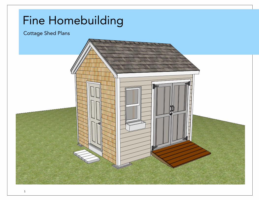
Gable-Wall Framing DetailWhile the exterior of these gable walls looks similar, the framing varies considerably. The traditionally framed wall on the left incorporates a double top plate that overlaps the adjacent walls. Studs are 16 in. on center, and there is a non-load-bearing header above the door. The gable will eventually be made from a truss as part of the roof framing. The gable wall on the left uses a balloon-framed approach; the studs are continuous from the bottom plateto the rake of the gable at the top plate. For a small shed like this, the structural attributes are nearly identical.
Double top plate
Single top plate
Bottom plate
Floor framing
8-in.-12 roof pitch
Non-load-bearing header
King stud
Trimmer stud supports header.
Non-bearing header
Rough sill
24 in.
Laps top plate of adjoining wall
16 in.
38 1/2 in.
95 3/4 in.
Page 7
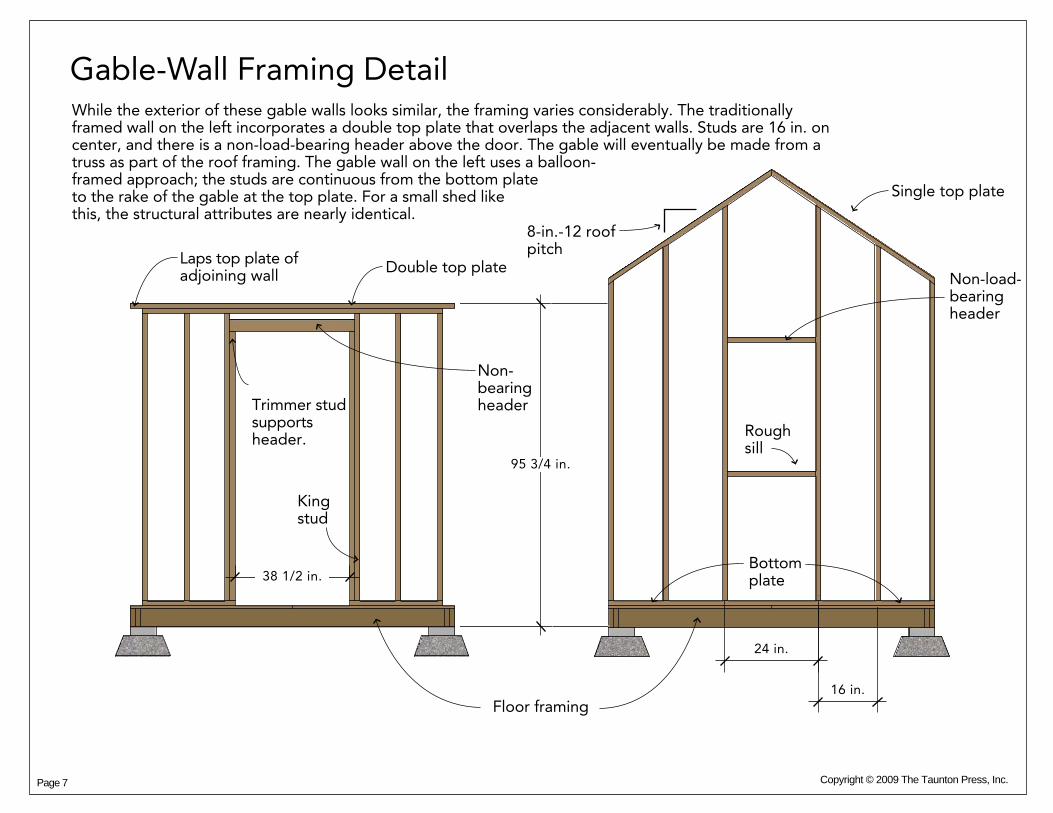
The roof trusses are constructed with 2x4 lumber to make up the bottom chord and two top chords (drawing right). The vertical blocking is necessary for the gable-end trusses to allow blocking for the wall sheathing. Plywood or OSB gussets (drawing lower right) are screwed to the 2x chords at the joints . To construct the trusses, draw the shape on the shed floor before the walls go up. Cut the piecesto fit on the shape, then fasten the gussets to make each truss rigid.
Truss Framing Detail
Bottom chord
1'
11 1/2"
1'
8 3/8"
Gusset to connect the top chord at peak
Copyright © 2009 The Taunton Press, Inc.
Blocking required only on gable-end truss
Top chord
Assemble the truss on the floor deck before the walls are assembled.
Gusset to connect the top and bottom chords at each end
8
12
12"
Roof pitch equals a 8-in. rise for a 12-in. run
1 1/2-in. nails
Page 8

Copyright © 2009 The Taunton Press, Inc.
Sheathing Detail
With traditional 2x framing, plywood or OSB (oriented strand board) panels provide most of the strength to resist shear forces such as wind or the weight of the structure itself. To maximize the the strength, panels are staggered at the seams, fastened to the framing lumber at regular intervals such as 12 in. to 16 in., and are glued to the framing under the floor panels.
Floor panels are glued to the framing with subfloor adhesive.
Doors and windows are cut out of full panels.
Stagger seams to prevent a weak configuration of so- called railroaded seams.
Page 9


![The Royal Borough of Windsor & Maidenhead · Cottage Brick _path Cottage Lower Wagtails Woodend C] Flint Cottage Redroots path path 73m ... Cottage Little Wood 132m Arbon Hill Cottage](https://img.pdfslide.net/doc/110x75/5f0da7e47e708231d43b6e94/the-royal-borough-of-windsor-maidenhead-cottage-brick-path-cottage-lower.jpg)