Embed Size (px)
Citation preview

.• 1' u 1
FIBER COMPOSITE ELEMENTS AND TECHNIQUES
AS NON-METALLIC REINFORCEMENT OF
CONCRETE
BRITE PROJECT 4142/ BREU- CT 910515
Evaluation of potentials and production technologies of FRP Technical report Task 1
F.S. Rostasy, Editor
Report No.: BREU 1-92
SICOM AKZO HBG iBMB/TU Braunschweig Magnel Laboratory Gent
September 1992
Digitale Bibliothek Braunschweig
http://www.digibib.tu-bs.de/?docid=00061522
I
TABLE OF CONTENTS
NOTATIONS
SUB-TASK 1.1 REQUIREMENTS FOR FRP FOR CONCRETE APPLICATION
1. PRINCIPAl OBJECTIVES
2. ON DEVELOPMENT AND INITIAl APPLICATIONS OF FRP TENSILE ElEMENTS
3. METHOD OF VALIDATION OF THE PROPERTIES OF FRP ElEMENTS
4. COMPARISON OF THE PROPERTIES OF FRP ElEMENTS WITH REINFORCING STEEl
5. COMPARISON OF THE PROPERTIES OF FRP ElEMENTS WITH PRESTRESSING STEEl 5.1 Shape, Diameter, Profile, Straightness
6.
5.2 Short-term Axial Strength 5.3 Long-term Axial Strength 5.4 Radial Strength
5.5 E-modulus (axial/radial), Strain at Failure, Elastic Strain,
Deformation Capacity 5.6 Poisson Ratio 5.7 Bending Capacity 5.8 0,1 %-Strain Force, 0,2 %-Strain Stress, Constriction 5.9 Interlaminar and Intralaminar Shear Strength, Transfer Length
5.10 Relaxation/Creep, Fatigue, Stress Rupture 5.11 Thermal Expansion (Axial/Radial)
5.12 Thermal Resistance, Fire Resistance 5.13 Corrosivity 5.14 Conductivity 5.15 Weight, Flexibility, Anchoring, Vulnerability, Toxicity 5.16 Durability
POTENTIAl FIELDS OF APPLICATION FOR FRP ELEMENTS 6.1 Fields of Application for AFRP Elements
6.2 Fields of Application for CFRP Elements
6.3 Fields of Application for GFRP Elements
Digitale Bibliothek Braunschweig
http://www.digibib.tu-bs.de/?docid=00061522
II
SUB-TASK 1.2 REVIEW AND APPRAISAL OF THE PROPERTIES OF UD-FRP ELEMENTS AND
THEIR PRODUCTION TECHNOLOGIES
1. SCOPE
2. FIBERS AND MATRIX MATERIALS 2.1 Introductory Remarks 2.2 Fibers for High-Strength Tensile Elements
2.2.1 Some Basic Requirements
2.2.2 Glass Fibers
2.2.3 Aramid Fibers 2.2.4 Carbon Fibers 2.2.5 Comparison of Fibers
2.3 Matrix Materials
2.4 Literature
3. SURVEY OF COMMERCIALLY AVAILABLE FRP ELEMENTS 3.1 Scope
3.2 Shapes 3.3 Production Technologies
3.3.1 Pultrusion 3.3.2 Prepregging
3.4 Overview on FRP Elements
3.5 Literature
4. STRENGTH AND DEFORMATION OF FRP 4.1 Scope
4.2 Mechanical Behaviour Under Short-Term Loading 4.2.1 Basic Relations
4.2.2 Elastic Constants and Composite Stresses
4.2.3 On Strength and Fracture Under Short-Term Loading
4.2.3.1 Axial stress-strain line and axial strength
4.2.3.2 Multiaxial strength
4.2.3.3 Modes of fracture
4.2.4 Influence of Temperature on Strength and Deformation 4.2.4.1 Practical relevance 4.2.4.2 Influence of temperature on the tensile strength of the
components
Digitale Bibliothek Braunschweig
http://www.digibib.tu-bs.de/?docid=00061522
5.
III
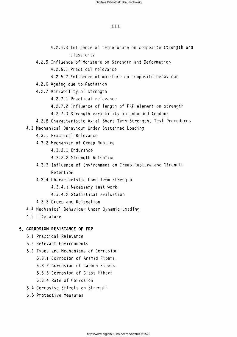
4.2.4.3 Influence of temperature on composite strength and
elasticity 4.2.5 Influence of Moisture on Strength and Deformation
4.2.5.1 Practical relevance
4.2.5.2 Influence of moisture on composite behaviour
4.2.6 Ageing due to Radiation
4.2.7 Variability of Strength
4.2.7.1 Practical relevance
4.2.7.2 Influence of length of FRP element on strength
4.2.7.3 Strength variability in unbonded tendons
4.2.8 Characteristic Axial Short-Term Strength, Test Procedures 4.3 Mechanical Behaviour Under Sustained Loading
4.3.1 Practical Relevance
4.3.2 Mechanism of Creep Rupture
4.3.2.1 Endurance
4.3.2.2 Strength Retention
4.3.3 Influence of Environment on Creep Rupture and Strength
Retention 4.3.4 Characteristic Long-Term Strength
4.3.4.1 Necessary test work
4.3.4.2 Statistical evaluation
4.3.5 Creep and Relaxation
4.4 Mechanical Behaviour Under Dynamic Loading
4. 5 Literature
CORROSION RESISTANCE OF FRP 5. 1 Practical Relevance
5.2 Relevant Environments
5.3 Types and Mechanisms of Corrosion
5. 3.1 Corrosion of Aramid Fibers
5.3.2 Corrosion of Carbon Fibers
5.3.3 Corrosion of Glass Fibers
5.3.4 Rate of Corrosion
5.4 Corrosive Effects on Strength
5.5 Protective Measures
Digitale Bibliothek Braunschweig
http://www.digibib.tu-bs.de/?docid=00061522
IV
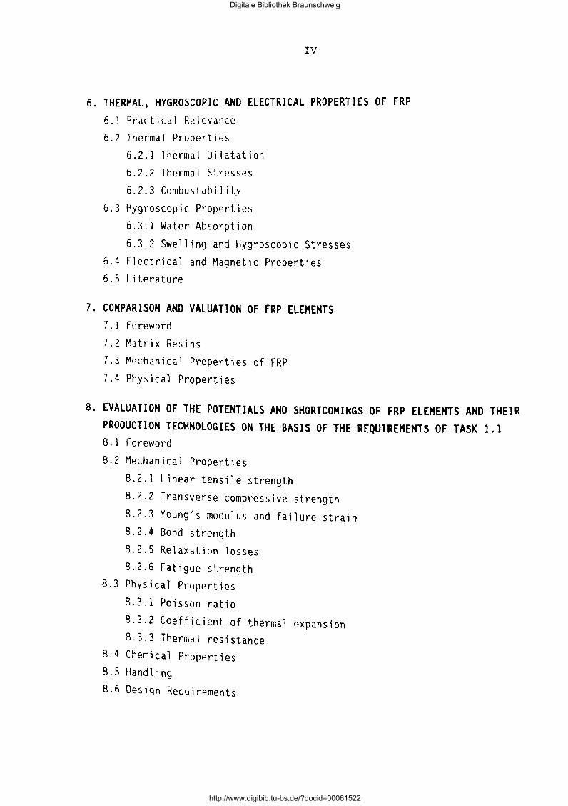
6. THERMAL, HYGROSCOPIC AND ELECTRICAL PROPERTIES OF FRP 6.1 Practical Relevance 6.2 Thermal Properties
6.2.1 Thermal Dilatation
6.2.2 Thermal Stresses 6.2.3 Combustability
6.3 Hygroscopic Properties
6.3.1 Water Absorption
6.3.2 Swelling and Hygroscopic Stresses
6.4 Electrical and Magnetic Properties 6.5 Literature
7. COMPARISON AND VALUATION OF FRP ELEMENTS 7.1 Foreword
7.2 Matrix Resins
7.3 Mechanical Properties of FRP 7.4 Physical Properties
8. EVALUATION OF THE POTENTIALS AND SHORTCOMINGS OF FRP ELEMENTS AND THEIR PRODUCTION TECHNOLOGIES ON THE BASIS OF THE REQUIREMENTS OF TASK 1.1 8.1 Foreword
8.2 Mechanical Properties
8.2.1 Linear tensile strength
8.2.2 Transverse compressive strength
8.2.3 Young's modulus and failure strain 8.2.4 Bond strength
8.2.5 Relaxation losses 8.2.6 Fatigue strength
8.3 Physical Properties
8.3.1 Poisson ratio
8.3.2 Coefficient of thermal expansion 8.3.3 Thermal resistance
8.4 Chemical Properties 8.5 Handling
8.6 Design Requirements
Digitale Bibliothek Braunschweig
http://www.digibib.tu-bs.de/?docid=00061522
V
9. SUGGESTIONS FOR MODIFICATIONS OF FRP ELEMENTS AND THEIR PRODUCTION TECHNOLOGIES 9.1 FRP Elements
9.2 Production Technologies
Digitale Bibliothek Braunschweig
http://www.digibib.tu-bs.de/?docid=00061522

VI
NOTATIONS (in accordance to EC2. pt.l)
1. UNITS For calculations, the following units are recommended:
forces and loads :kN, kN/m, kN/m2
unit mass :kg/m3
unit weight :kN/m3
stresses and strengths :N/mm2 (= MPa; = MN/m2)
moments (bending ... ) :kNm
strain ··; • 0 0
2. LATIN UPPER CASE SYMBOLS 2.1 Geometry
A Area (in general) Ab Total cross sectional area of a concrete section
Ab,eff Abt Ac Af
Am Ap As
As,min Asl
Asz
As,prov As,req
As,surf Ast Asv lb R
T
wb wt
Effective tensile zone of reinforcement
Tensile zone in the uncracked state of concrete Total cross sectional area of a composite element
Total cross sectional area of fibers
Total cross sectional area of resin matrix
Area of a prestressing steel unit Area of reinforcement within the tensile zone Minimum area of longitudinal tensile reinforcement
Area of tension reinforcement effective at the section
Area of compressive reinforcement Area of steel provided
Area of steel required
Area of surface reinforcement
Area of a transverse bar
Additional transverse steel perpendicular to the lower face Second moment of area of a concrete section Curvature radius of tendon Torsional moment
Section modulus of concrete Torsional resistance moment
Digitale Bibliothek Braunschweig
http://www.digibib.tu-bs.de/?docid=00061522
VII
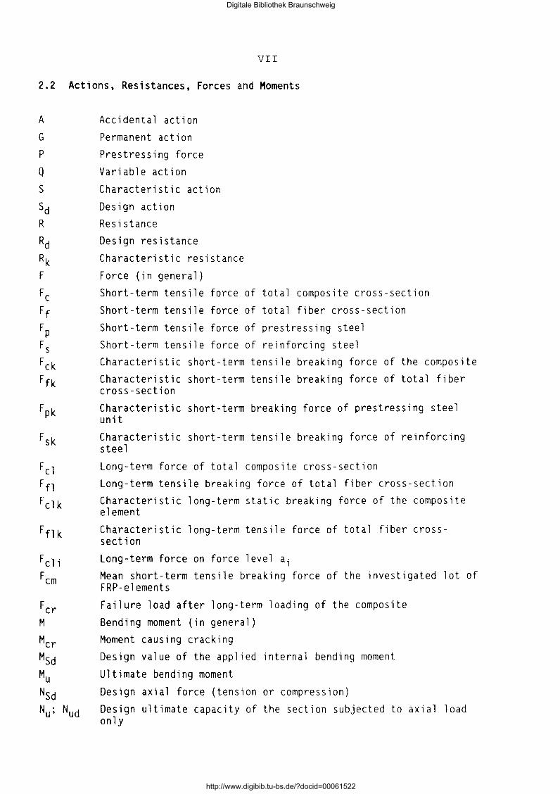
2.2 Actions, Resistances, Forces and Moments
A G
p
Q
s
sd R
Rd Rk F
Fe Ff
FP Fs
F ck Ffk
Fpk
Fsk
Fcl Ffl
Fclk
F fl k
F cl i Fern
Fer M
Mer Msd Mu
Nsd Nu; Nud
Accidental action Permanent action Prestressing force Variable action
Characteristic action Design action Resistance Design resistance Characteristic resistance
Force (in general) Short-term tensile force of total composite cross-section
Short-term tensile force of total fiber cross-section Short-term tensile force of prestressing steel Short-term tensile force of reinforcing steel Characteristic short-term tensile breaking force of the composite Characteristic short-term tensile breaking force of total fiber cross-section Characteristic short-term breaking force of prestressing steel unit Characteristic short-term tensile breaking force of reinforcing steel
Long-term force of total composite cross-section Long-term tensile breaking force of total fiber cross-section Characteristic long-term static breaking force of the composite element Characteristic long-term tensile force of total fiber crosssection Long-term force on force level a; Mean short-term tensile breaking force of the investigated lot of FRP-elements Failure load after long-term loading of the composite Bending moment (in general) Moment causing cracking Design value of the applied internal bending moment
Ultimate bending moment
Design axial force (tension or compression)
Design ultimate capacity of the section subjected to axial load only
Digitale Bibliothek Braunschweig
http://www.digibib.tu-bs.de/?docid=00061522
pd
Pk inf; pk:sup PO
DPsl DP~(x)
DPc(t)
VIII
Design value of the prestressing force at the ultimate limit state
Lower and upper characteristic value of the prestressing force for serviceability calculations Initial force at the active end of the tendon immediately after stressing Maximum permissible value of P0
Mean value of the prestressing force immediately after stressing (post-tensioning) or transfer (pre-tensioning) at any point distance along the member (i.e. the force after immediate losses have occured)
Mean value of the prestressing force at time t, at any point distance x along the member
Mean value of the prestressing force, after all losses have occured, at any point distance x along the member Ultimate shear capacity
Loss of prestress
Loss of prestress due to elastic deformation of the member at transfer
Loss of prestress due the anchorage slip Loss of prestress due to friction
Loss of prestress due to creep, shrinkage and relaxation at time t
2.3 Materials
Eb Modulus of elasticity of normal weight concrete Ebd Design value of the secant modulus of elasticity
Ebm Secant modulus of elasticity of normal weight concrete
Eb(t) Tangent modulus of elasticity of normal weight concrete at time t
Eb(28) Tangent modulus of elasticity of normal weight concrete at 28 days Ebc,eff Effective modulus of elasticity of normal weight concrete ELc; ELb,mSecant modulus of elasticity of lightweight concrete Ec Modulus of elasticity of composite Ef Modulus of elasticity of fiber Em Modulus of elasticity of matrix
Es Modulus of elasticity of reinforcement or prestressing steel
Digitale Bibliothek Braunschweig
http://www.digibib.tu-bs.de/?docid=00061522
IX
3. LATIN LOWER CASE LETTERS 3.1 Geometry
b Overall width of a cross-section, or actual flange width in aT or L beam
beff bz bw
bw,nom c
min c
f
fc,s
ftot h
hf k
l
lb 1ba
le le 1eff ln
10 1p,eff
s
Effective flange width of a T or L beam Width of the tensile cross section Width of the web on t, I or L beams
Effective width of the web
Concrete cover
Minimum concrete cover
Effective depth of a cross-section
Diameter of a prestressing duct
Largest nominal maximum aggregate size Diameter of a composite bar,etc.
Diameter of an individual fiber Diameter of a reinforcing or prestressing bar
Eccentricity
Deflection
Increase of deflection due to creep and shrinkage
Total deflection
Overall depth of a cross-section Overall depth of a flange in T or L beams Unintentional angular displacement of the tendons
Length, span (in general)
Basic anchorage length for reinforcement
Anchorage length over which the tendon force in pretensioned members is fully transmitted to the concrete
Transmission lenghth over which the prestressing force is fully transmitted to the concrete
Free length between anchorages Gage length for the measurement of the axial strain
Effective span of a beam
Clear distance between the faces of the supports
Length of span(s) between points of zero moment
Dispersion length, over which the concrete stresses gradually disperse to a linear distribution across the section (effective transfer)
Spacing of the stirrups
Minimal vertical or horizonal distance of tendons
Digitale Bibliothek Braunschweig
http://www.digibib.tu-bs.de/?docid=00061522
u
Vf vm
wk X, y, z
z
zcp
X
Perimeter of concrete cross section, having area Ab
Fiber volume in a composite cross section Matrix volume in a composite cross section
Design crack width
Coordinates Lever arm of internal forces Distance between the centre of gavity of the concrete section and the tendons
3.2 Materials
f strength (in general)
fb Compressive strength of concrete
fbk,cube fbm
fbtk fbtm f btk,O.OS f btk,0.95 fbt,ax fbt,fl fbt,sp fc
fck
fcri fcrs fr
ff
ffk
fm
fmk fp
fpk
fpO.l fpO.lk ft
ftk fy
Characteristic compressive cube strength of concrete at 28 days Mean value of concrete cylinder compressive strength Characteristic axial tensile strength of concrete
Mean value of axial tensile strength of concrete
Lower characteristic tensile strenth (5% fractile)
Upper characteristic tensile strength (95% fractile) Axial tensile strength of concrete
Flexural tensile strength of concrete Splitting tensile strength of concrete Tensile strength of composite
Characteristic tensile strength of composite
interlaminar shear strength of a composite surface strength of a composite
bond strength between composite and concrete Tensile strength of fiber of a composite
Characteristic short-term tensile strength of fiber Tensile strength of matrix of a composite
Characteristic strength of matrix of a composite Tensile strength of prestressing steel
Characteristic tensile strength of prestressing steel 0.1% proof-stress of prestressing steel
Characteristic 0.1% proof-stress of prestressing steel Tensile strength of reinforcement
Characteristic tensile strength of reinforcement Yield stress of reinforcement
Digitale Bibliothek Braunschweig
http://www.digibib.tu-bs.de/?docid=00061522
XI
fyd Design yield strength of reinforcement fyk Characteristic yield stress of reinforcement
fywd Design yield strength of stirrups
4. GREEK LOWER CASE LETTERS 4.1 Geometry
a Inclination of shear reinforcement to the member axis
a Angle, ratio b Spread angle of the prestressing force
1 Ratio (As/Ab) 1 Coefficient of friction between the tendons and their ducts
4.2 Strain and Stress
a; Force level (Fc1/Fcm) e Strain (in general)
eu Ultimate strain eb Compressive strain in the concrete
ebu Ultimate compressive strain in the concrete ebs Basic shrinkage strain for normal weight concrete ebsoo Final shrinkage strain for normal weight concrete eu Elongation of reinforcement or prestressing steel at maximum load
ec Elongation of composite at maximum load
ecc Creep strain tf Elongation of fiber at maximum load
em Elongation of matrix at maximum load ep Elongation of prestressing steel at maximum load et Elongation of reinforcing steel at maximum load Dec Variation of elongation in the composite Dep Variation of elongation in the prestressing steel
r Stress (in general)
r(t0
) ;r(t) Stress at time t 0 or t Stress in concrete
Stress in the concrete adjacent to the tendons, due to self-weight and any other permanent actions Initial stress in the concrete adjacent to the tendons, due to prestress
Digitale Bibliothek Braunschweig
http://www.digibib.tu-bs.de/?docid=00061522
rbs
rbt re rf rm rp
XII
Compressive stress in the centre of gravity of a concrete cross section
Tensile stress in concrete Stress in a fiber composite Stress in an individual fiber of a composite Stress in matrix Stress in prestressing steel
rm; ru; r 0 Middle-, lower- and upper stress under dynamic action
Drpr
Drp,c+s+r
s
Or
Or rel
Variation of stress in the tendons at section x due to relaxation
Variation of stress in the tendons due to creep, shrinkage and relaxation
Shear stress
Stress variation between lower and upper stress Variation of stress of a composite due to relaxation
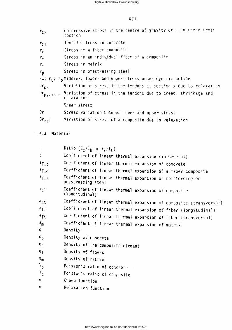
4.3 Material
a
a
act afl aft am q
qb
QC
qf
qm
lb
l c u
w
Ratio (Es/Eb or Ec/Eb)
Coefficient of linear thermal expansion (in general)
Coefficient of linear thermal expansion of concrete
Coefficient of linear thermal expansion of a fiber composite Coefficient of linear thermal expansion of reinforcing or prestressing steel
Coefficient of linear thermal expansion of composite (longitudinal)
Coefficient of linear thermal expansion of composite (transversal)
Coefficient of linear thermal expansion of fiber (longitudinal)
Coefficient of linear thermal expansion of fiber (transversal) Coefficient of linear thermal expansion of matrix Density
Density of concrete
Density of the composite element Density of fibers Density of matrix
Poisson's ratio of concrete
Poisson's ratio of composite Creep function
Relaxation function
Digitale Bibliothek Braunschweig
http://www.digibib.tu-bs.de/?docid=00061522

4.4
Cp
5.
n
r
V
XIII
Safety
Partical safety factors for accidental actions A Partial safety factors for concrete material properties
Partial safety factors for actions, F
Partial safety factors for permanent actions G
Partial safety factor for material property, taking account of uncertainties in the material properties itself and in the design model used
Partial safety factors for actions associated with prestressing, p
Partial safety factors for variable actions Q Partial safety factor for the properties of reinforcement and prestressing steel
Partial safety factor for actions without taking account of model uncertainties
Partial safety factor for permanent actions without taking account of model undertainties
Partial safety factor for a material property, taking account only of uncertainties in the material property
OTHER SYMBOLS
Number of load cycles
Number of load cycles until fracture
Temperature
Temperature difference
Total number of wires and strands in a tendon
Time being considered
Time at initial loading of concrete
Time under load until fracture
Time under force Fcli until fracture
Mean value
Standard deviation
Coefficient of variation
Digitale Bibliothek Braunschweig
http://www.digibib.tu-bs.de/?docid=00061522

Digitale Bibliothek Braunschweig
http://www.digibib.tu-bs.de/?docid=00061522
-1-
SUB-TASK 1.1 REQUIREMENTS FOR FRP FOR CONCRETE APPLICATION
1. PRINCIPAL OBJECTIVES
Sub-task 1.1 of the work program of BREU-91 05 15 deals with the formulation
of the main requirements high-strength FRP tensile elements will have to
meet in order to be economically and successfully applied for reinforced and
prestressed concrete construction. These requirements must be studied and
formulated with respect to the following criteria:
a) Service of performance of structural concrete members, deformation,
cracking, stiffness under service load and environmental influence.
b) Load carrying capacity when loaded in bending, by normal forces and in
shear etc.
c) Design of structural concrete members by taking into account the specific
properties of FRP and by considering the optimal techn i ea l and economic
utilization of the virtues of FRP.
d) Aspects of the production of precast concrete members and of on-site
works taking into account the specific properties of FRP.
These aspects will be dealt with further-on on basis of our knowledge on
structural concrete reinforced or prestressed with steel.
Digitale Bibliothek Braunschweig
http://www.digibib.tu-bs.de/?docid=00061522
-2-
2. ON DEVELOPMENT AND INITIAL APPLICATIONS OF FRP TENSILE ELEMENTS
Structural concrete members are conventionally reinforced and/or prestressed
by steel elements, in the shape of bars and meshes and/or prestressing steel
elements such as wires, bars or strands. In structural concrete. the steel
is embedded in concrete or cementitious grout and thereby protected against corrosion by the high alkalinity of the pore solution of the concrete cover
or of the grout as long as the passivity of the steel surface exists. In
spite of this undisputable protective property of concrete and grout, prema
ture losses of durability due to steel corrosion are being increasingly ob
served all over the world. This is especially true if the structural members
are subjected to severe environmental exposure. Serious technical and econo
mic damages arise, endangering the structural integrity, shortening the span
of service life of structures.
Structural concrete industry has reacted to these damages in many ways. A
plurability of structural, technological and executional countermeasures
were developed to enhance durability. Roughly speaking, two main avenues of development can be distinguished. One avenue adheres to steel as reinforcing
and prestressing material but exploits all possibilities for an improved ac
tive and passive protection of the steel against corrosion (e.g. low-permea
bility concrete, zinc and epoxy coating of steel, etc.). The other avenue represents the quest for new non-corroding materials as an alternative to steel. Because stainless steel is unacceptable for structural concrete due
to its cost this quest inevitably led to Fiber Reinforced Plastics, abbreviated FRP.
FRP are a group of advanced composite materials. FRP are not an invention
but the result of steady evolution. They are not in a static but already in
a dynamic state of development. This evolution was initiated by a variety of industries for engineering applications other than structural concrete. Today, FRP are indispensable materials for aircrafts, automobiles, for many types of sports gear etc. The structural concrete industry is the beneficiary of this evolution.
Digitale Bibliothek Braunschweig
http://www.digibib.tu-bs.de/?docid=00061522
-3-
There are many types of FRP, with more to emerge in the future. FRP consist
of thin and strong fibers of different chemical origin embedded in a matrix.
Because here the potential use of FRP as high-strength tensile elements for
structural concrete is in the focus of attention. only the unidirectional
(ud) arrangement of virtually endless fibers in a polymeric resin matrix
will be dealt with. It should be mentioned that for the above-mentioned
other applications the multidirectional (md) arrangement of fibers is predo
minantly used to obtain plate-shaped elements (laminates). It is expected
that in future the use of md-laminates for structural profiles will gain mo
mentum. Such profiles will lead to solutions competetive to structural
s tee 1 .
The FRP tensile elements - in the shape of rods, strips, strands, and also
in thin plates - which are suitable for the reinforcing and/or prestressing
of concrete members, exhibit a series of assets. Some of these assets make
FRP equivalent to reinforcing or prestressing steel, others prove to be su
perior. These assets comprise:
- high and adjustable tensile strength and modulus of elasticity,
excellent corrosion resistance to a plurality of environments aggressive
to steel,
- very low specific weight,
-magnetic and electric neutrality.
It should not be suppressed that there are a 1 so drawbacks. One serious
obstacle is the high price of FRP per weight unit at present. But as FRP are
being increasingly used for many applications mainly other than civil engi
neering structures, their price decreases from year to year. Besides if the
price per tonne of force is considered the economic gap between prestressing
steel and FRP is rapidly vanishing, with FRP weighing one sixth to one
fourth of steel per volume.
FRP are strong when stressed axially but very sensitive against lateral
pressure. This phenomenon calls for new ways of anchorage design and of
structural detailing. Some types of FRP are sensitive to the high alkalinity
of concrete, others however are entirely insensitive.
Digitale Bibliothek Braunschweig
http://www.digibib.tu-bs.de/?docid=00061522
-4-
The above described assets of FRP caught the interest of the structural con
crete industry searching for a non-corroding alternative to steel. In coope
ration with the chemical industry and scientists all over the world FRP
high-strength tensile elements are being developed and applied. Strong acti
vities of technical committee work can be observed. International conferen
ces report on the state of art which is in steady progress.
Following laboratory research, first applications in real scale are realized
in many countries. Especially in Europe and Japan, first bridges and struc
tures using FRP tensile elements for the pre- and post-tensioning of con
crete are being built. Some of these applications have already been in ser
vice successfully for five to ten years. FRP are also being used for the ep
oxy-bonded external strengthening of concrete structures.
FRP are a materials group in many ways different from reinforcing and pre
stressing steel. This calls for new ways of testing and design, of structu
ral detailing and for new methods for the reliable anchorage and transfer of
force. To give guidance in these problems is the goal of this report.
Digitale Bibliothek Braunschweig
http://www.digibib.tu-bs.de/?docid=00061522
-5-
3. METHOD OF VALIDATION OF THE PROPERTIES OF FRP ELEMENTS
If in the future FRP should be increasingly used as a non-corroding alterna
tive to prestressing and reinforcing steel for structural concrete applica
tions a comparison of the most important properties with steel can serve as
a starting point for the validation of FRP.
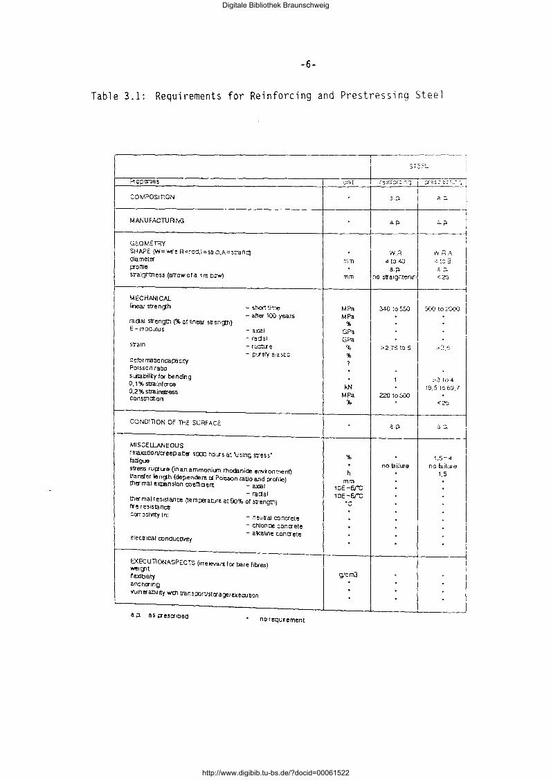
Reinforcing and prestressing steels are well-developed materials. They are
standardized in most countries. The requirements and values shown in Table
3.1 represent a compilation of properties mainly on basis of the European
Standards pr EN 10198 and pr EN 10080. The main purpose of this table is to
serve as a checklist of properties to be known or discussed or to be used
for reference.
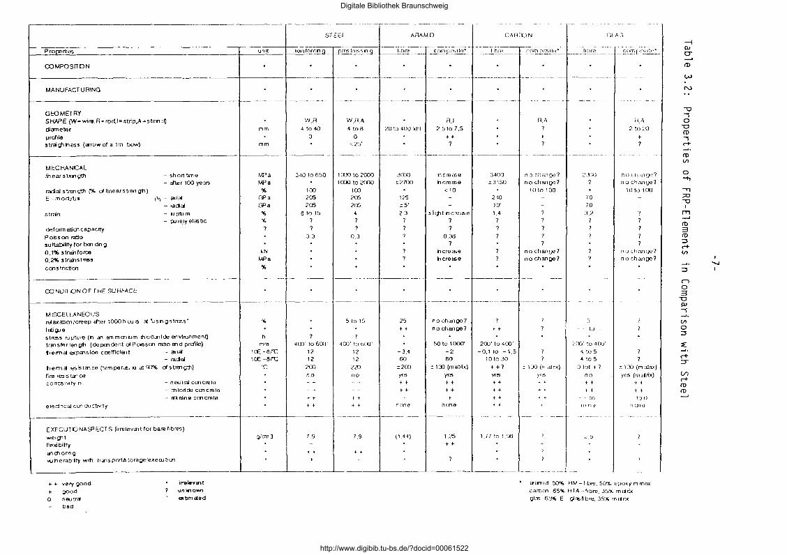
In Table 3.2 the properties of reinforcing steel and prestressing steel are
compared with the properties of the fiber of the equivalent FRP tensile ele
ments as they are developed and known until now.
A fundamental difference between steel and the FRP elements is steel being a
one component material and FRP consisting of at least two components. FRP is
therefore also ea ll ed a composite. A FRP element can be modified either by
changing the properties of the fiber or the matrix or by changing both. A
further difference which has to be taken into account is the fact that steel
is more or less an isotropic material and FRP an anisotropic one. The pro
perties in different directions can therefore differ dramatically in FRP
tensile elements. The findings on material properties of SUB-TASK 1.2 are
taken into account.
Digitale Bibliothek Braunschweig
http://www.digibib.tu-bs.de/?docid=00061522
-6-
Table 3.1: Requirements for Reinforcing and Prestressing Steel
SE::l.
Properoes L.;;llt r e;r.t:r:;~ Q i P""'c ""P"c- ~~ I --- --.. ,, 1 COMPOSITION a;J. a:l I MANUFACTUPJNG ap. a.;:>
GEOMETRY I SHAPE (W= wre,R=roO,\ =S'JIP,A= strancl} 'H,R 'H,P .A. era meter mm 4 to 40 ~ :o a p-onle . a;J. a p. Slraigntness (arrow or a 1 m bow) mm no stra1gntenlf1 <25
MECHANICAL I near stre n ~h -short time M ?a 340 to550 Y'JO t 0 20(()
- after 100 years M ?a . racial S1rengtn (%or linear stren;Jli) % . E-maautus - aXJal GPa
- raclal GPa strain - ruptl..le % >2,75 to 5 >3,5
- plJ'ety elasoc % aeror maoonca!=flclty 1 Polsson rabO . sUtability for benang . 1 >3 to 4 0, 1% strainfcroa kN . 18.5 to 69.7 0.2% strainstress M ?a 220 to500 consondJon
% <25
CONDITION OF THE SURFACE ap. a;J.
MISCElLANEOUS
relaxaOoll/C'eep arter 1IXO noLrs at 'using stress' % 1,5-4 fatigue . no lailure no nilure stress ru11ure (inanammoniun rhodanide envronment) h . 1,5 transfer len~h (dependent c:i Poisson ratio and p-ofile) mm trlermal exp;J.nslon coernoent - aXJal
tDE-6/"C - raaal 1DE-6/"C
trler mal resistance (temperarure at S()% or s:rengm) ·~
tre resistance " ccrroslvrty In: - neutral concrete .
- chlonde concrete . - al<alme concrete
electrical conoucOvrty . . EXECU110NASPECTS (1ne\evant for bare fibres) Wl!lglt
gicm1 nex~b11ity
ancna1ng . . vutneraiOUity wt111 transp:Jrtlslaagelexec:uoon
.
a.p. as j:TeScrlbea no requrement
Digitale Bibliothek Braunschweig
http://www.digibib.tu-bs.de/?docid=00061522
Pro~ roes
OOMPOSrTON
MANUFACTURING
GEOMETRY SH.APE (W• wire.R: rod. I~ strip ,A ~strm d)
dianeter
pn:lila • tra \11 ., es • (a-row of a 1 m bowl
MECHANCAL
!near st""' Qlh -short lime - !Iter 100 yeas
rajj al s 1Jm gth (% of linear s trm gfl) E -modJI.Js (1.) - a<ial
- mdal
stran - up\Jre - purely ei<E tic
deform aticn capacrty
Por;son ra!lo •u ltability for bm <fn g 0,1% strai11orca 0,2% stra11strms
ems tnctJcn
OONOrfONOF THE SURFACE
--------~---------
M ISCEUANEDUS relaxaDcn/creep !Iter 1000 h ru os ~ \Jsnostress·
Id! OJ 9 stress rupture (n a-1 <rnmcnum 1!1od<:nlde environment)
Inn s le r lm gfl (depmdent oiPocsson rano rnd prdlle)
t>erm!l expa'lslon crefficlmt - .(ll(laf
- racial
tlerma resr;ta'lce (temper.ru"' at OCJ% of s lrn1 (;1!1)
(ire res s ta1 ce corra5t"-1ty n: - neutra!crnc~ta
- d'llor1de cm crete
- akaJn 9 ccn cr\lte
eleclncal cm ductJvrty
EXECUTONAPECT S Qmeteva1t for bare fibres)
wer(flt lie xi brlty
a'1 cr10nn Q
"'11 e rabrlty wrtl
+ + very oood
+ oood o nrutra
bad
trJls pat..!5 toraoe/exerutJcn
i~Telev;nt
unlno'NI'l <~~nm 1fed
unrt
.
mm
mm
M' a M' a
'l(,
G'a G'a
'l(,
'l(,
7
kN I.'Pa
'l(,
------
%
h mm
leE -6/"C teE -6/"C
c
g/011)
---------~--- -
STEEL
rtin lorcn Q"- ()IT;;j tressllJl._
. . f------- -------~----·- f---
. ---~-- ---------
W,R W,fl,A 4 to 40 4 to 6 2
0 0 . <25'
340 to 650 1 COO 10 :?COO . 1000 to 2COO 100 100 2aJ 2aJ 2aJ 2aJ
8 to 15 4 7 7 7 7
0,3 0.3
. . .
----~ --------
. -- --- ---------
5 to 15
7 7 400' to 600' 4Cll' to &CD'
12 12 12 12
:?CO 2aJ no no ---
- -
t + t + + + + t
--- --~--- --
7 g 7.9 - -
t + • t
t
------'--
ARAMO
0 to 400 kfrl
--~-----·-
J(J)Q
,2700
t<S ~s·
2.3 7
25 t t
-3.4 50
::2CO yes t t
t t
nn1e
(1.44)
ll.l 2,5to7,5
++ 7
~--·------·
ncrna;a hcreme
<10
sh~t r1cre<Ee 7 7
0.3U 7
ncreRJe hcram9
-·--·--·--
no chango?
no change?
50 to 1000'
-2 80
~DJ (mmrix)
yes ++ t +
nme
1.25 t +
CAr1lUN
3400 !:3150
240 10'
1,4 7 7 7
t +
200' to 400'
-0,1 to -1.5 tOto 30
+ + 7 yes
+ + ++ t + • +
1.77 to 1.00
c~_e~~=---- _____ _!.!tJrt"! ______ _
H.A l1.A
7 2 lo ~'()
~ ~
7 7
no change? ;>J)() no cll;uloe? no change? 7 no change?
1Uto 100 10 to ioo 10
70
3.2 7
?
no chanve7 7 no Lt1anve?
no change? ? no change?
to
2[)]' 10 40J'
4 to 5 4 to 5
-'lXl(m<Unx) 0 tot t 7 c 1 Xl (m alnx)
)'f.'S nD y<S (m ;tlix) t t t t ++ t • t t t + + t to !.)()
n(ne nmo
-------~
.!,t)
Jallld :OX.. ~1M- f1t:fe, 50% epoxy m mn.x
carbcn 65% HTA -rrbre. 35% m1frix
IJias 5~ E glas~bre. 35% mltrtx
Digitale Bibliothek Braunschweig
http://www.digibib.tu-bs.de/?docid=00061522

-8-
4. COMPARISON OF THE PROPERTIES OF FRP ELEMENTS WITH REINFORCING STEEL
The properties which have to be looked upon first are the mechanical proper
ties. Are the mechanical properties of FRP elements comparable to the pro
perties of the normal reinforcing steel in order to be an alternative?
Aramid and glass FRP:
As a result of the relatively low E-modulus aramid (AFRP) and glass (GFRP)
based FRP tensile elements are mainly fit to be used as prestressing mate
rial. The use of these elements as reinforcement would result in relatively
large deformations and wide cracks. One could deal with this fact by increasing the fiber volume.
Carbon FRP:
The E-modulus of carbon based elements can be higher than of steel. However
the deformation capacity of CFRP is very low compared to reinforcing steel because the plastic deformation of steel is lacking.
The different stress strain curves for steel, aramid carbon and glass are given in Fig. 4.3 of TASK 1.2.
As a result of this analysis the field of application of the FRP elements will be confined to the use as prestressing elements. Therefore in the fol
lowing only the use of the elements as alternative for prestressing steel will be discussed.
Digitale Bibliothek Braunschweig
http://www.digibib.tu-bs.de/?docid=00061522
-9-
5. COMPARISON OF THE PROPERTIES OF FRP ELEMENTS WITH PRESTRESSING STEEL
The items are discussed in the same order in which they appear in Table 3.2:
5.1 Shape; Diameter; Profile; Straightness
Design of FRP tendons with respect to geometrical appearance 1s strongly re
lated to the prescriptions of manufacturers. It is possible to shape FRP in
either rods, strips or strands, depending on the requirements of applica
tion. This is also true for the diameter. Experience shows that certain pro
files are necessary to give the FRP prestressing tendons the desired proper
ties for pre-tensioning. The fact that the FRP-tendons need to be profiled
adds to the splitting force problem, which is related to the thermal expan
sion behaviour and the Poisson effect as well.
The idea is to start from the existing FRP tendons regarding geometrical
shape. From the investigations it will be possible to conclude whether ad
justments or alterations will be necessary.
5.2 Short-term Axial Strength
The short-term axial strength values of the different FRP types are more
than sufficient in comparison to steel. Therefore no further investigation
regarding this matter will therefore be necessary.
5.3 Long-term Axial Strength
This property is strongly related to other properties such as relaxation,
fatigue, stress rupture, and corrosivity (since the environment always ln
fluences long-term properties). It will therefore be discussed for each FRP
type in a special paragraph "durability" at the end of this chapter.
5.4 Radial Strength
In the case of aramid-based FRP the low radial strength restricts applica
tion possibilities to those where the FRP will not be subjected to direct
transverse forces. For the other FRP this depends on the 1 eve l of radial
strength.
Digitale Bibliothek Braunschweig
http://www.digibib.tu-bs.de/?docid=00061522
-10-
5.5 E-modulus (axial/radial); Strain at Failure; Elastic Strain; Deformation
Capacity
As shown in Fig. 4.3 of Task 1.2 a fundamental difference between steel and
FRP elements based on either aramid, carbon or glass is the shape of the
stress-strain curve.
At a certain level of stress steel starts to show plastic deformation. This
will be the case at overloading. If the load subsequently is removed the de
formation will partly remain. If the FRP elements are overloaded and subse
quently the load is removed these elements will return to their original
shape.
The values of E-modulus and strain of the FRP are sufficient to be used as prestressing elements. Research will be based on the properties of the existing materials. Whether it will be necessary to alter these basic pro
perties will follow from further application oriented research.
5.6 Poisson Ratio
Compared to the Poisson ratio of steel FRP in general have greater Poisson
ratios. This may lead to higher splitting forces (Hoyer effect) in the force transfer zone of pre-tensioned members which may reach the concrete tensile strength. Modifications will then be necessary to control this phenomenon.
5.7 Bending Capacity
In the case of prestressing applications this property has an execution vul
nerability aspect but it is merely of significance for reinforcing steel and
will therefore not be further discussed this document. When investigating
the suitability of FRP for reinforced concrete it should however be kept in mind.
5.8 0,1 %-Strain Force; 0,2 %-Strain Stress; Constriction
These properties are deducted from specific requirements for prestress i ng
and reinforcing steel. FRP show different strain behaviour than steel. Con
striction of steel takes place during the plastic deformation part of the
stress-strain curve, which is nonexistent with FRP. Constriction with respect to FRP is therefore not an item to investigate. Due to this absence
Digitale Bibliothek Braunschweig
http://www.digibib.tu-bs.de/?docid=00061522

-11-
of plastic deformation behaviour totally different criteria have to be ap
plied to FRP in determining ultimate values up to where they can be respon
sibly prestressed. Following from the above no investigation is needed.
5.9 Interlaminar and Intralaminar Shear Strength; Transfer Length
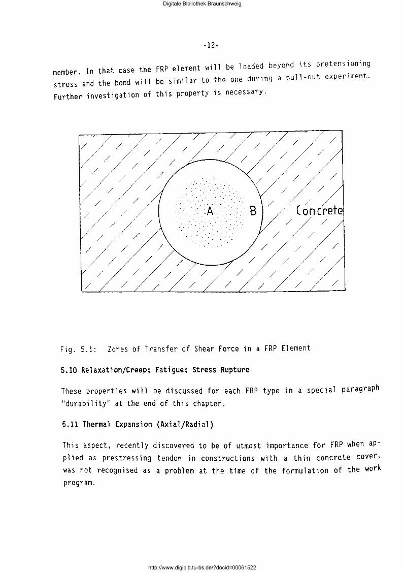
The shear force transfer over the cross-section of a FRP element and its
surrounding concrete can be modelled on the basis of Fig. 5.1 of the cross
section.
Fig. 5.1 shows that several discontinuities will be encountered. The core A
is an anisotropic material consisting of fibers and matrix, whereas 8 and C
will be considered more or less isotropic is this discussion.
Within A:
The force transfer between the fibers takes place by means of a resin. The
quantification of this transfer can be referred to as intralaminar shear
strength. This is an important property which must be further investigated.
Between A and B:
The quantification of the force transfer between the fiber containing core
of the element and its coating, which may consist of either the same or a
different resin, is referred to as interlaminar shear strength. This pro
perty will influence the transfer length, which may be an advantageous side
effect, provided that the minimum steel requirements regarding transfer
length will be met. Further investigation of this property is necessary.
Between B and C:
The force transfer between the element and the concrete/grout (resp. Band
C) is quantified by the minimum length which is necessary to transfer a cer
tain unit of force and reffered to as transfer length. Whereas most experi
mental transfer length determinations are based on "pull-out" tests the ac
tual relevant behaviour should be determined by "push-in" tests, because the
Poisson ratio works in favor of the bond to concrete in the case of a pre
tensioned FRP element. The results of pull-out tests have so far been satis
factory and since the push-in results will be even better no problems have
to be expected here, except during failure of the FRP pretensioned concrete
Digitale Bibliothek Braunschweig
http://www.digibib.tu-bs.de/?docid=00061522
-12-
member. In that case the FRP element will be loaded beyond its pretensioning stress and the bond will be similar to the one during a pull-out experiment.
Further investigation of this property is necessary.
/ / / /
/ / / /
/ /
/ /
/ /
/ / / ~;;//
/ / /
// / /
/ /
.. ' .... · .. · .. .......... : · > ·. : · ·. · .. A.·. · .. : ~ : ... · B . . . . . . . . . ' ... .
/ / /
Concrete / /
/ /
/ /
/ / / /
/ /
/ / /
Fig. 5.1: Zones of Transfer of Shear Force in a FRP Element
5.10 Relaxation/Creep; Fatigue; Stress Rupture
These properties will be discussed for each FRP type in a special paragraph
"durability" at the end of this chapter.
5.11 Thermal Expansion (Axial/Radial)
This aspect, recently discovered to be of utmost importance for FRP when apP 1 i ed as prestress i ng tendon in constructions with a thin concrete cover' was not recognised as a problem at the time of the formulation of the work program.
Digitale Bibliothek Braunschweig
http://www.digibib.tu-bs.de/?docid=00061522
-13-
In the case of aramid-based FRP the radial thermal expansion coefficient is
significantly greater than the axial one (which is even negative). The pro
blem is that it exceeds the concrete thermal expansion coefficient substan
tially. Although the radial thermal expansion coefficients of the bare car
bon and glass fibers are substantially lower than that of aramid it is their
composite behaviour that counts. The resin applied to these FRP alternatives
causes them to show a thermal expansion behaviour similar to aramid composi
tes. This characteristic deserves great attention and requires thorough in
vestigation.
5.12 Thermal Resistance; Fire Resistance
Exposure to very low temperatures does not lead to problems in the case of
aramid-based FRP. Tests so far even indicated that the FRP-concrete bond is
improved by it. Whether this is the case for the other FRP types is unknown.
The applied resins are thermo-setting so heating does not affect the compo
site properties negatively and therefore no specific vulnerability during
storage or other execution stages has to be feared. The behaviour regarding
fire resistance must however be investigated for applications where this is
a requirement.
5.13 Corrosivity
See paragraph durability, where this item is discussed for each FRP type.
5.14 Conductivity
The conductivity behaviour is different for the FRP types, which results in
a differing suitability for applications where specific conductivity charac
teristics are required.
5.15 Weight; Flexibility; Anchoring; Vulnerability; Toxicity
FRP are no health hazard and can easily be handled due to flexibility and
low density.
In spite of a relatively low radial strength in the case of aramid-based FRP
there are no reasons to believe that handling of FRP should take place with
more care than prestressing steel. However this aspect must be looked at.
Digitale Bibliothek Braunschweig
http://www.digibib.tu-bs.de/?docid=00061522
-14-
Neither difficulties with regard to concreting 1n hum1d cond1tions nor de
stressing problems are expected to occur. Extended exposure to ultraviolet
light may affect FRP properties and must be investigated.
5.16 Durability
Durability of AFRP
The stress-rupture behaviour and the sensitivity of AFRP to an alkaline en
vironment calls for new requirements. This is illustrated in Fig. 4.18 of
Sub-Task 1.2, which shows the behaviour of a strip. The stress-rupture line
represents the relation between the stress in a tensile element and the time that passes before the material fails under a specific sustained stress level. Of importance is also the residual tensile strength after a preceding
long-term static force. The long term strength is also presented in Fig.
4.18. It can be seen that the residual strength of an unloaded strip after
100 years exposition to an alkaline environment like concrete is about 85%
of the short term strength. This value has been obtained by means of an ex
trapolation using the Arrhenius principle, that describes a relation between
residual strength, temperature and time. Tests at elevated temperatures thus give indications about the residual strength under normal circumstances.
In assessing the structural safety one has to estimate the final prestres
sing level, taking into account all losses caused by the creep and shrinkage
of the concrete and by relaxation of the FRP. This value must be compared with the characteristic stress-rupture curve.
Due to the non-corrosivity of FRP crack width is no design criterion unless for aesthetical reasons.
Durability of CFRP
The durability of CFRP in any kind of environment dangerous to steel is to be rated as excellent. CFRP are also superiour to the other kinds of FRP.
Durability of GFRP
The durability of GFRP elements when exposed to normal weather is superior to steel and equivalent to AFRP and CFRP. Chloride ions do not affect GFRP. Immediate contact with aqueons solutions of high alkalinity is however dele-
Digitale Bibliothek Braunschweig
http://www.digibib.tu-bs.de/?docid=00061522
-15-
tereous to GFRP. Such environments exist in fresh concrete and grout. Improvement becomes necessary by substituting the UP-matrices by EP-matrices in conjunction with special coatings. Further research is necessary.
Main Conclusions
The main conclusions are drawn by pointing out the important differences to
reinforcing and prestressing steel by the way of comparison of FRP with the 1 atter.
AFRP Elements
better resistance to aggresive environments
- higher fatigue strength
- higher deformation capacity (low E-modulus)
- higher electrical resistivity
- non-magnetic
- fully elastic stress strain behaviour
- lower strain at failure - higher creep and relaxation
- greater deformations (low E-modulus)
thermal expansion behaviour very different from that of concrete
CFRP Elements
Most of the statements apply also for CFRP. But several differences must be
pointed out:
- similar modulus of elasticity
- rather low ultimate strain
- superior corrosion resistance
- lower relaxation
GFRP Elements
Most of the statements made for AFRP with respect to the comparison with
steel also apply for GFRP. The major differences to steel are:
Digitale Bibliothek Braunschweig
http://www.digibib.tu-bs.de/?docid=00061522
-16-
- lower fatigue strength
-better resistance to aggressive external environment but less resistant
when embedded in concrete or grout
- equivalent relaxation and creep
From these conclusions we can deduce that for post-tensioning applications
all FRP seem fit. In pre-tensioning cases however the direct concrete con
tact is a problem for glass, due to alkaline corrosion. FRP on a carbon ba
sis are, apart from being less economic than aramid-based FRP. interesting
materials for pre-tensioning applications.
Digitale Bibliothek Braunschweig
http://www.digibib.tu-bs.de/?docid=00061522

-17-
6. POTENTIAL FIELDS OF APPLICATION FOR FRP ELEMENTS
Based on the conclusions of chapter 5 the promising fields of use for the
different FRP alternatives are given below:
6.1 Fields of Application for AFRP Elements
-As storage tanks resulting from its behaviour under low temperature condi
tions.
- As railway sleepers resulting from its excellent fatigue behaviour.
-As structural concrete members with very thin concrete cover due to its
non-corrosivity.
- In defence transport industry due to its non-corrosivity.
- Inreligious/health/electronic apllications due to its non-corrosivity.
As a result of these conclusions, focus will be put on pre-tensioning with
AFRP with ARAPREE. Possibilities for other FRP do however exist and there
fore more or less parallel investigations must be carried out for all FRP
where useful.
The application of Arapree will be investigated specifically within BRITE
EURAM for the following applications:
- Pretensioned concrete elements for agro-applications which are exposed to
severe corrosive environment.
- Balcony slabs, reinforced by Arapree-prestressed-bars.
- Railway sleepers
- Bank protection with the use of Arapree prestressed piles
("Perkoenpaaltjes") and shutters.
- Soil anchors - Shutter shelves (e.g. as a substitution of tropical hardwood)
6.2 Fields of Application for CFRP Elements
Most of the potential fields of application presented for AFRP also seem to
be open for CFRP. Because of their high modulus of elasticity which can be
modified in such a way to be in the range of steel CFRP can be used for:
- Reinforcement for bending members and for secondary reinforcement
- Meshes
Digitale Bibliothek Braunschweig
http://www.digibib.tu-bs.de/?docid=00061522
-18-
- Ground anchors in very aggressive soil and water - Post-tensioning tendons, structural ties and stay cables
6.3 Fields of Application for GFRP Elements
As experience has shown GFRP high-strength tensile elements can be success
fully used for:
- Tendons for the post-tensioning of concrete structures. - Ground and rock anchors.
- Structural ties, stay cables.
Incorporation of opto-electronic and electric sensors for supervision of structures.
Digitale Bibliothek Braunschweig
http://www.digibib.tu-bs.de/?docid=00061522
-19-
SUB-TASK 1.2 REVIEW AND APPRAISAL OF THE PROPERTIES OF UD-FRP ELEMENTS AND THEIR PRODUCTION TECHNOLOGIES
1. SCOPE
All technical properties of FRP elements strongly depend on the properties
of the components fiber and matrix. In consequence. at first the properties
of suitable fibers and matrix materials have to be dealt with on basis of
the literature and of the knowledge of the partners. Then a survey of com
mercially available FRP elements suitable for structural concrete and the
state of the art on composite behaviour and experimental results is presen
ted.
For the successful pursuit of the BRITE EURAM research and development work
the presently available FRP elements and their production technologies are
evaluated. The findings of SUB-TASK 1.2 are taken into consideration for the
conclusions of SUB-TASK 1.1.
Digitale Bibliothek Braunschweig
http://www.digibib.tu-bs.de/?docid=00061522
-20-
2. FIBERS AND MATRIX MATERIALS
2.1 Introductory Remarks
Fiber composites are being developed and used for a great variety of engi
neering applications. Several types of fibers and matrix materials have
emerged. The types of fibers are: glass fibers, aramid fibers, carbon fi
bers, boron fi bers, ceramic fi bers and met a 11 i c fi bers. For the production
of linear tensile FRP elements for the purpose of prestressing and reinfor
cing of structural concrete only glass fibers, carbon fibers and aramid fi
bers have been successfully used up to now. Only these types of fibers will
be dealt with furtheron.
Also the matrix materials show a great variety: polymer matrix, metal ma
trix, ceramic matrix. For the purposes dealt with in this report only poly
mer matrices are suitable: polyester, epoxy, and vinylester resin.
Finally, because of the application of FRP for structural engineering only
the unidirectional arrangement of fibers within the polymer matrix is relevant.
2.2 Fibers for High-Strength Tensile Elements
2.2.1 Some Basic Requirements
Fibers for the manufacture of tensile elements in structural engineering
must meet several basic requirements. From the structural point of view a
high strength, a high modulus of elasticity and a sufficient elongation at
the tensile fracture of fiber are necessary. Durability requires a high re
sistance to the environmental to which the structure will be subjected and
also to the micro-environmental actions within the structural element (e.g. within the concrete).
Digitale Bibliothek Braunschweig
http://www.digibib.tu-bs.de/?docid=00061522
-21-
Furthermore, the diameter of fiber should be as small as possible, because
strength increases with diminishing fiber diameter. This requirement also
leads to the increase of the so-called aspect ratio 1/d which expresses the
norma 1 i zed necessary bond 1 ength for the transfer of force from broken fi
bers to unbroken fibers.
The following sections give a condensed overview on fibers suitable for uni
directional fiber composites for the reinforcement and prestressing of con
crete. Their main properties and processes of manufacture are described in
[2.1] and [2.2].
2.2.2 Glass Fibers
Glass fibers are widely used for the production of FRP. Common fibers are
made of E-glass (::::55% Si02;:::: 8% Al 2o3 ; :::: 19% CaO; :::: 5% MgO). Stronger
and more resistant to alkaline solutions, though more expensive than E-glass
fibers, are fibers made from C- and S-glass (:::: 65% Si02; :::: 25 % Al 2o3 ; 0%
CaO; z 10% MgO). The strength of glass fibers is dependent on the magnitude
and density of surface defects which may be inflicted during handling etc.
For the protection of the fiber its surface is treated immediately after fi
ber drawing with a thin polymeric coat compatible with polymeric matrices.
This coat also improves the bond with the matrix.
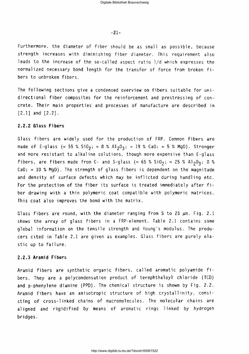
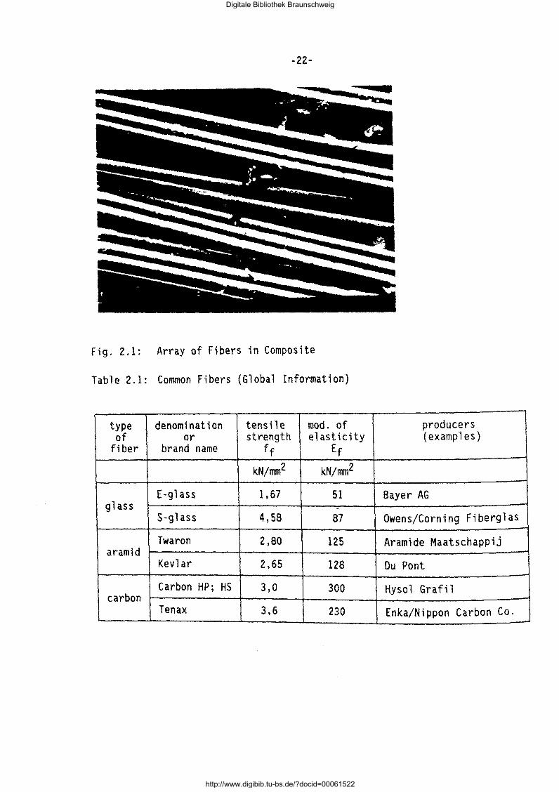
Glass fibers are round, with the diameter ranging from 5 to 25 ~m. Fig. 2.1
shows the array of glass fibers in a FRP-element. Table 2.1 contains some
gl oba 1 information on the tens i 1 e strength and Young's modulus. The produ
cers cited in Table 2.1 are given as examples. Glass fibers are purely ela
stic up to failure.
2.2.3 Aramid Fibers
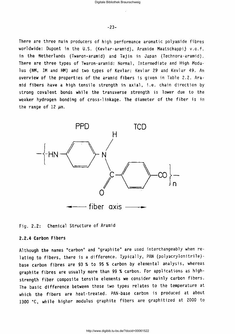
Aramid fibers are synthetic organic fibers, called aromatic polyamide fi
bers. They are a polycondensation product of terephthaloyl chloride (TCD)
and p-phenylene diamine (PPD). The chemical structure is shown by Fig. 2.2.
Aramid fibers have an anisotropic structure of high crystallinity, consi
sting of cross-linked chains of macromolecules. The molecular chains are
aligned and rigidified by means of aromatic rings linked by hydrogen
bridges.
Digitale Bibliothek Braunschweig
http://www.digibib.tu-bs.de/?docid=00061522
-22-
fig. 2.1: Array of Fibers in Composite
Table 2.1: Common Fibers (Global Information)
type denomination tensile mod. of producers of or strength elasticity (examples)
fiber brand name ff Ef
kN/mm2 kN/mm2
E-glass 1,67 51 Bayer AG glass -
S-glass 4,58 87 Owens/Corning Fiberglas
Twaron 2,80 aramid
125 Aramide Maatschappij
Kevlar 2,65 128 Du Pant
Carbon HP; HS 3,0 300 Hysol Grafi 1 carbon
Tenax 3,6 230 Enka/Nippon Carbon Co.
Digitale Bibliothek Braunschweig
http://www.digibib.tu-bs.de/?docid=00061522
-23-
There are three main producers of high performance aromatic polyamide fibres
worldwide: Dupont in the U.S. (Kevlar-aramid), Aramide Maatschappij v.o.f.
in the Netherlands (Twaron-aramid) and Tejin in Japan (Technora-aramid).
There are three types of Twaron-aramid: Normal, Intermediate and High Modu
lus (NM, IM and HM) and two types of Kevlar: Kevlar 29 and Kevlar 49. An
overview of the properties of the aramid fibers is given in Table 2.2. Ara
mid fibers have a high tensile strength in axial, i.e. chain direction by
strong cava 1 ent bonds while the transverse strength is 1 ower due to the
weaker hydrogen bonding of cross-linkage. The diameter of the fiber is in
the range of 12 ~m.
PPD TCD H
I -i-HN N
\ I \ eo}~ le 0
• fib er OX IS ...
Fig. 2.2: Chemical Structure of Aramid
2.2.4 Carbon Fibers
Although the names "carbon" and "graphite" are used interchangeably when re
lating to fibers, there is a difference. Typically, PAN (polyacrylonitrile)
base carbon fibres are 93 % to 95 % carbon by e 1 ementa 1 ana 1 ys is, whereas
graphite fibres are usually more than 99% carbon. For applications as high
strength fiber composite tensile elements we consider mainly carbon fibers.
The basic difference between these two types relates to the temperature at
which the fibers are heat-treated. PAN-base carbon is produced at about
1300 •c, while higher modulus graphite fibers are graphitized at 2000 to
Digitale Bibliothek Braunschweig
http://www.digibib.tu-bs.de/?docid=00061522
-24-
3000 •c. Graphite fibers have high strength and very high moduli. These pro
perties remain constant at high temperatures.
A basic disadvantage of the use of carbon fibers for high strength fiber composite tensile elements in structural engineering is their cost. They
st i 11 are by volume about 7 to 10 times more expensive than steel. The raw
materials, or precursors, for PAN-base fibers are expensive. and the proces
ses of carbonization and graphitization consume much time, energy and mate
rials and require close control throughout.
Some producers and some brand names of carbon fibers are given in Table 2.1. Table 2.3 shows several properties of HM (high elastic modulus) and HT (high
tenacity) carbon fibers. For the application of such fibers for tensile ele
ments an adequate ultimate strain at fiber fracture is essential. Carbon fi
bers are highly corrosion resistant. Their diameter is in the range of 5 to 10 t.Lm.
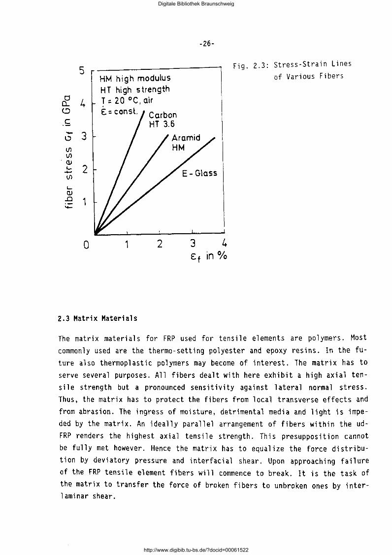
2.2.5 Comparison of Fibers
The fibers treated here are compared with each other and with high-strength prestressing steel with respect to selected properties for the application.
Fig. 2.3 compares the af-Ef-lines of several fiber types. In Table 2.4
several properties of FRP are compared with each other and with highstrength, colddrawn prestressing steel.
Digitale Bibliothek Braunschweig
http://www.digibib.tu-bs.de/?docid=00061522
-25-
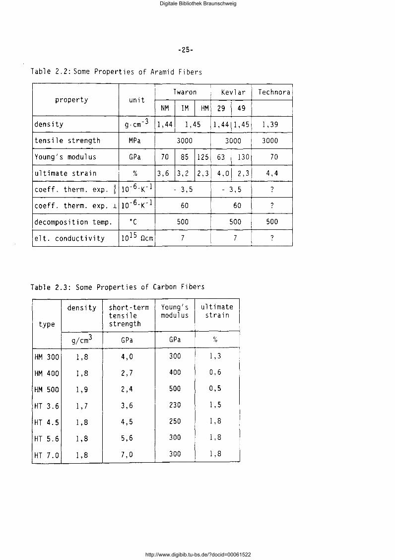
Table 2.2: Some Properties of Aramid Fibers
Twaron Kevlar Technora property unit
NM IM HM 29 49
density g·cm-3 1,44 1,45 1, 44 1, 45 1, 39
tensile strength MP a 3000 3000 3000
Young's modulus GP a 70 85 125 63 130 70
ultimate strain % 3,6 3,2 2,3 4,0 2,3 4,4
coeff. therm. exp. 11 10-6.K-1 - 3,5 - 3' 5 ?
coeff. therm. exp. J.. 10-6.K-l 60 60 ?
decomposition temp. ·c 500 500 500
elt. conductivity 10 15 Ocm 7 7 ?
Table 2.3: Some Properties of Carbon Fibers
density short-term Young's ultimate tensile modulus strain
type strength
gjcm3 GP a GP a %
HM 300 1,8 4,0 300 1, 3
HM 400 1 '8 2,7 400 0,6
HM 500 1 '9 2,4 500 0,5
HT 3.6 1 '7 3,6 230 1, 5
HT 4.5 1 '8 4,5 250 1 '8
HT 5.6 1,8 5,6 300 1 '8
HT 7.0 1 '8 7,0 300 1, 8
Digitale Bibliothek Braunschweig
http://www.digibib.tu-bs.de/?docid=00061522
0 0.. <.:)
c -..., lJ} lJ}
'(l) I---lJ}
L... (l) .0 -
5
4
3
2
1
0
HM high modulus HT high strength T = 20 °C, air E: = const.
1 2
2.3 Matrix Materials
-26-
F. 2 3· Stress-Strain Lines 1 g. . . of Various Fibers
3 4 Et in °/o
The matrix materials for FRP used for tensile elements are polymers. Most commonly used are the thermo-setting polyester and epoxy resins. In the future also thermoplastic polymers may become of interest. The matrix has to serve several purposes. All fibers dealt with here exhibit a high axial tensile strength but a pronounced sensitivity against lateral normal stress. Thus, the matrix has to protect the fibers from local transverse effects and from abrasion. The ingress of moisture, detrimental media and light is impeded by the matrix. An ideally parallel arrangement of fibers within the udFRP renders the highest axial tensile strength. This presupposition cannot be fully met however. Hence the matrix has to equalize the force distribution by deviatory pressure and interfacial shear. Upon approaching failure of the FRP tensile element fibers will commence to break. It is the task of the matrix to transfer the force of broken fibers to unbroken ones by interlaminar shear.
Digitale Bibliothek Braunschweig
http://www.digibib.tu-bs.de/?docid=00061522
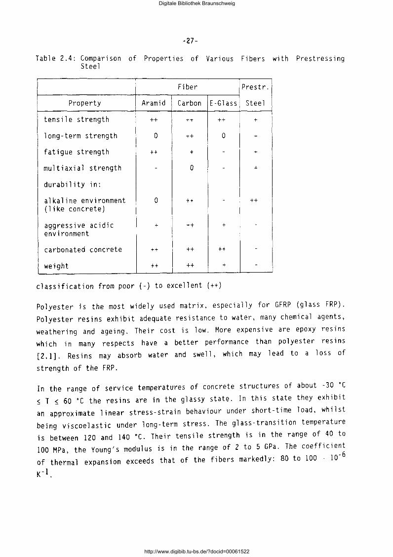
-27-
Table 2.4: Comparison of Properties of Various Fibers with Prestressing Steel
Fiber Prestr.
Property Aramid Carbon E-Glass Steel '
tensile strength ++ ++ ++ +
long-term strength 0 ++ 0 +
fatigue strength ++ + - +
multi axi a 1 strength - 0 - +
durability in:
alkaline environment 0 ++ - ++ (like concrete)
aggressive acidic + ++ + -
environment
carbonated concrete ++ ++ ++ -
weight ++ ++ + -
classification from poor (-) to excellent (++)
Polyester is the most widely used matrix, especially for GFRP (glass FRP).
Polyester resins exhibit adequate resistance to water, many chemical agents,
weathering and ageing. Their cost is low. More expensive are epoxy resins which in many respects have a better performance than polyester resins
[2.1]. Resins may absorb water and swell, which may lead to a loss of
strength of the FRP.
In the range of service temperatures of concrete structures of about -30 oc $ T $ 60 oc the resins are in the glassy state. In this state they exhibit
an approximate linear stress-strain behaviour under short-time load, whilst
being viscoelastic under long-term stress. The glass-transition temperature is between 120 and 140 oc. Their tensile strength is in the range of 40 to 100 MPa, the Young's modulus is in the range of 2 to 5 GPa. The coefficient
of thermal expansion exceeds that of the fibers markedly: 80 to lOO · 10-6
K -1.
Digitale Bibliothek Braunschweig
http://www.digibib.tu-bs.de/?docid=00061522
-28-
It has to be pointed out that microcracks in the resin matrix may arise when
using FRP elements for prestressing (1 to 1,5% strain). This may have ad
verse effects on the durability of the FRP. Matrix resins with ultimate ten
sile strains of 4 to 6% are desirable.
The behaviour of a composite is also influenced by the interface between fi
ber and matrix. The flow of force between fiber and matrix requires adequate
interfacial bond [2.1]. Bond can be classified in mechanical and chemical
bond. Mechan i ea l bond (shear key effect) seems not to be very efficient.
Chemi ea 1 bond and adhesion by wetting are the more important effects. They
are enhanced by coupling agents and the surface sizing or treatment of fi
bers.
2.4 Literature
[2.1] Chawla, K. K.: Composite Materials. Science and Engineering. Sprin
ger-Verlag, New York, 1987.
[2.2] Tsai, S. W. and Hahn, H. T.: Introduction to Composite Materials.
Technomic Publ. Co. Westport Conn./USA, 1980.
Digitale Bibliothek Braunschweig
http://www.digibib.tu-bs.de/?docid=00061522
-29-
3. SURVEY OF COMMERCIALLY AVAILABLE FRP ELEMENTS
3.1 Scope
The FRP tensile elements dealt with here are ud-composites of fibers which are fully embedded in epoxy or polyester matrices. They can be utilised for the reinforcing and/or prestressing of structural concrete. In addition, they can be applied for ground and rock anchors, for structural ties and other purposes.
FRP elements are not standardized, neither on national nor on international
levels. Hence, it will become necessary to mention brand names and producers
of FRP to give the interested reader the opportunity to contact producers for further information. It should be noted that the overview on types, brand names and producers of FRP is unbiased and incomplete. The literature sources [3.1] to [3.11] present an overview on the use of AFRP, GFRP and
CFRP for the reinforcement and prestressing of concrete.
3.2 Shapes
Most of the FRP tensile elements have either a circular or rectangular
cross-section (round bars or flat strip). Diameter of round bars are typically in the range of 4 to 10 mm. Flat strips have cross-sectional areas of
up to 150 mm2.
FRP elements used for the pre-tensioning of concrete members may be surfacetreated to improve bond. The surface may be: sand-coated, shaped or knurled.
FRP elements are produced by a continuous process. They may be coated on
line with a polyamide or polypropylene coat for additional protection. Table
3.1 gives an overview on products. In addition to compact FRP elements, recently also strands with seven and more CFRP wires were developed.
3.3 Production Technologies
Nowadays in principle two different technologies are applied for the produc
tion of unidirectional fiber composites. The most common technology is pul
trusion. The often applied prepreg method is used for the production of mul
tidirectional and plain composites.
Digitale Bibliothek Braunschweig
http://www.digibib.tu-bs.de/?docid=00061522
-30-
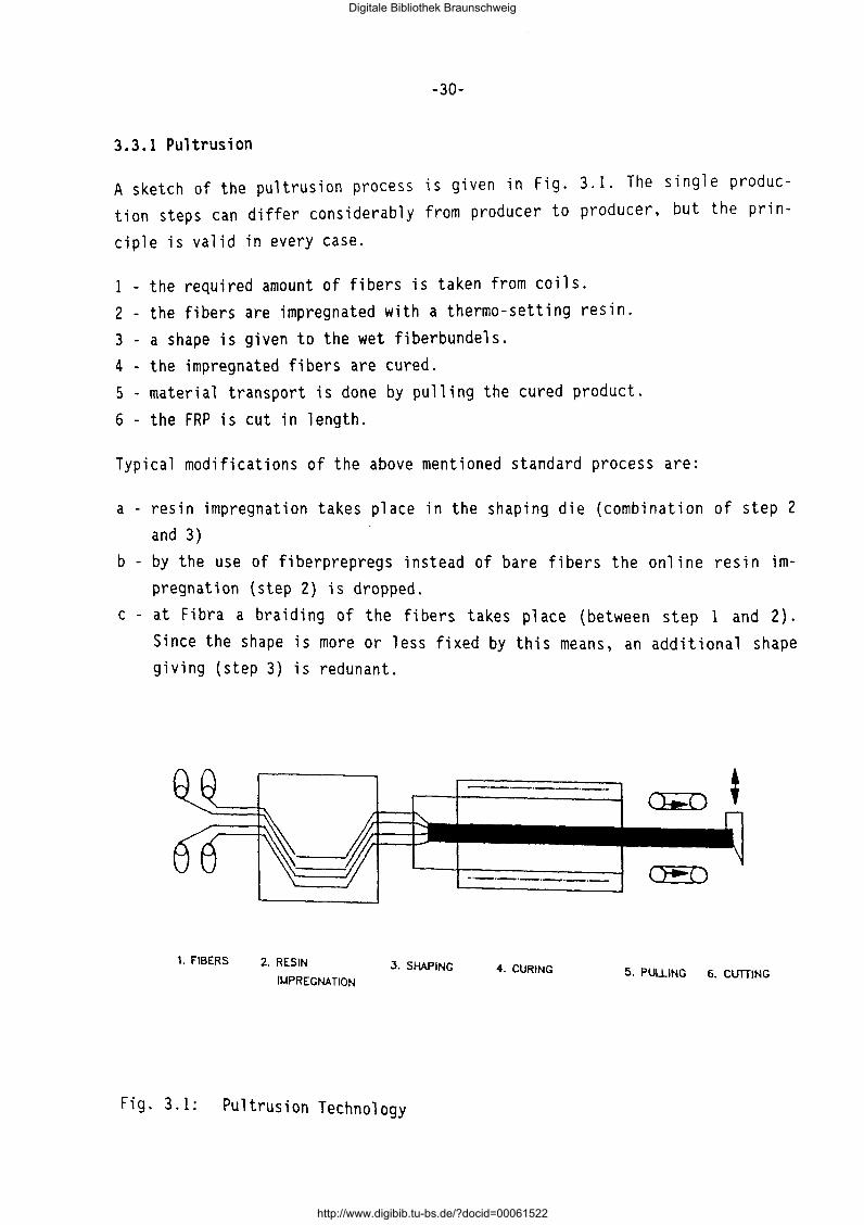
3.3.1 Pultrusion
A sketch of the pultrusion process is given in Fig. 3.1. The single production steps can differ considerably from producer to producer, but the prin
ciple is valid in every case.
1 - the required amount of fibers is taken from coils. 2 - the fibers are impregnated with a thermo-setting resin. 3 - a shape is given to the wet fiberbundels. 4 - the impregnated fibers are cured. 5 - material transport is done by pulling the cured product. 6 - the FRP is cut in length.
Typical modifications of the above mentioned standard process are:
a - resin impregnation takes place in the shaping die (combination of step 2 and 3)
b- by the use of fiberprepregs instead of bare fibers the online resin impregnation (step 2) is dropped.
c-at Fibra a braiding of the fibers takes place (between step 1 and 2). Since the shape is more or less fixed by this means, an additional shape giving (step 3) is redunant.
1. FIBERS 2. RESIN
II.IPREGNATION 3. SHAPING
Fig. 3.1: Pultrusion Technology
(~()
~()
4. CURING 5. PULLING 6. CUTTING
Digitale Bibliothek Braunschweig
http://www.digibib.tu-bs.de/?docid=00061522
-31-
Usual process parameters of pultrusion and dimensions of the products are:
production speed: 0.5 m/min + 2.0 m/min cross-section surface size
3.3.2 Prepregging
round, flat, multishaped smooth 1 mm + 50 mm
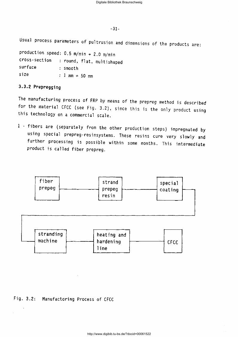
The manufacturing process of FRP by means of the prepreg method is described for the material CFCC (see Fig. 3.2), since this is the only product using this technology on a commercial scale.
1 - fibers are (separately from the other production steps) impregnated by using special prepreg-resinsystems. These resins cure very slowly and further processing is possible within some months. This intermediate product is called fiber prepreg.
fiber strand special prepeg prepeg coating
resin
stranding heating and machine hardening CFCC
line
Fig. 3.2: Manufactoring Process of CFCC
Digitale Bibliothek Braunschweig
http://www.digibib.tu-bs.de/?docid=00061522

-32-
Table 3.1: Several Manufacturers of FRP for Civil Engineering Applications
manufacturer country fiber matrix brandname
Akzo NL A,C EP Arapree Arisawa J A,C,G EP Bayer AG 0 G UP Polystal Bridon Composites GB A,C,G EP,UP Bri-ten Cousin F G UP JONCS JT IMCO USA G UP Kuraray J PVA EP Mitsubishi Kasei J c EP Leadline Mitsui constr. J A EP Fibra Polygon USA G EP Pultrall CAN G UP Isorod Sport ex 0 G EP Teijin J A VE AFRP rod Tokyo rope J c EP CFCC
A= aramid, C = carbon, G =glass, PVA = polyvinyl alcohol, EP = epoxy, UP = unsaturated polyester, VP = vinylester
2 - by stranding plural pieces of fiber prepregs, a piece of strand prepreg is fabricated.
3 - the surface of the strand prepreg is treated by special coating and turned into a composite linear body.
4 -plural composite linear bodies are stranded and turned into a composite stranded body.
5 - the composite stranded body is finally heated and hardened.
The process parameters of the CFCC production and the dimensions of the products are:
production speed: 0.5 m/min (estimated) cross-section surface
size
round
slightly structured 1.3 mm+ 40 mm
The following comparison of the above mentioned production technologies comprises only economic and technological items. A comparison of the material properties is given later.
Digitale Bibliothek Braunschweig
http://www.digibib.tu-bs.de/?docid=00061522
-33-
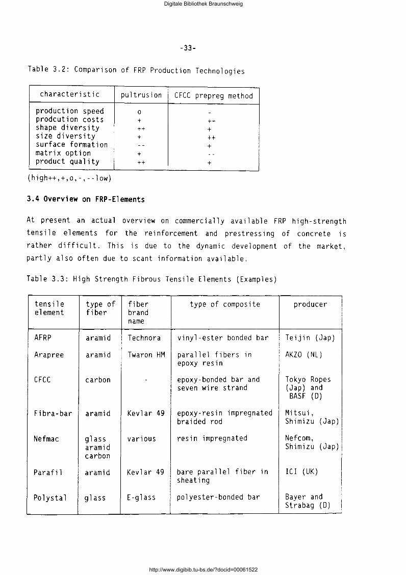
Table 3.2: Comparison of FRP Production Technologies
characteristic pultrusion CFCC prepreg method
production speed 0 -prodcution costs + ++ shape diversity ++ + size diversity + ++ surface formation -- + matrix option + - -
product quality ++ +
(high++,+,o,-,--low)
3.4 Overview on FRP-Elements
At present an actual overview on commercially available FRP high-strength tensile elements for the reinforcement and prestressing of concrete is
rather difficult. This is due to the dynamic development of the market, partly also often due to scant information available.
Table 3.3: High Strength Fibrous Tensile Elements (Examples)
tensile type of fiber type of composite producer element fiber brand
name
AFRP aramid Technora vinyl-ester bonded bar Teijin (Jap)
Arapree aramid Twaron HM parallel fibers in AKZO (NL) epoxy resin
CFCC carbon - epoxy-bonded bar and Tokyo Ropes seven wire strand (Jap) and
BASF (D)
Fibra-bar aramid Kevlar 49 epoxy-resin impregnated Mitsu i, braided rod Shimizu ( Jap)
Nefmac glass various resin impregnated Nefcom, a ram id Shimizu (Jap) carbon
Parafi 1 a ram id Kevlar 49 bare para ll e 1 fi ber in ICI (UK) sheating
Polys tal glass E-glass polyester-bonded bar Bayer and Strabag (D)
Digitale Bibliothek Braunschweig
http://www.digibib.tu-bs.de/?docid=00061522
-34-
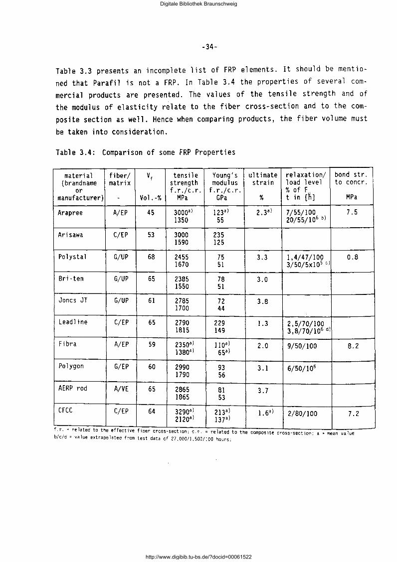
Table 3.3 presents an incomplete list of FRP elements. It should be mentioned that Parafil is not a FRP. In Table 3.4 the properties of several commercial products are presented. The values of the tensile strength and of the modulus of elasticity relate to the fiber cross-section and to the composite section as well. Hence when comparing products, the fiber volume must
be taken into consideration.
Table 3.4: Comparison of some FRP Properties
materia 1 fiber/ vf tensile Young's ultimate relaxation/ bond str. (brandname matrix strength modulus strain 1 oad 1 eve 1 to concr.
or f.r./c.r. f.r.jc.r. % of F manufacturer) - Vo 1 . -% MP a GP a % t in (~] MP a
Arapree A/EP 45 30ooal 123al 2 .3a) 7/55/100 7.5 1350 55 20/55/106 b)
Arisawa C/EP 53 3000 235 1590 125
Polystal G/UP 68 2455 75 3.3 1,4/47/100 0.8 1670 51 3/50/5xl05 cl
Bri -ten G/UP 65 2385 78 3.0 1550 51
Joncs JT G/UP 61 2785 72 3.8 1700 44
Leadline C/EP 65 2790 229 1.3 2,5/70/100 1815 149 3,8/70/106 d)
Fibra A/EP 59 235oal 11 oal 2.0 9/50/100 8.2 138oal 65al
Polygon G/EP 60 2990 93 3.1 6/50/106
1790 56
AERP rod A/VE 65 2865 81 3.7 1865 53
CFCC C/EP 64 329oal 2120a)
213al 137al
1. 6a) 2/80/100 7.2
f.r. :related to the effective fiber cro - -_ ss sectlon, c.r. related to the compos1te cross-sectwn; a: mean value b/c/d- value extrapolated from test data of 27,000/1,500/100 hours;
Digitale Bibliothek Braunschweig
http://www.digibib.tu-bs.de/?docid=00061522
-35-
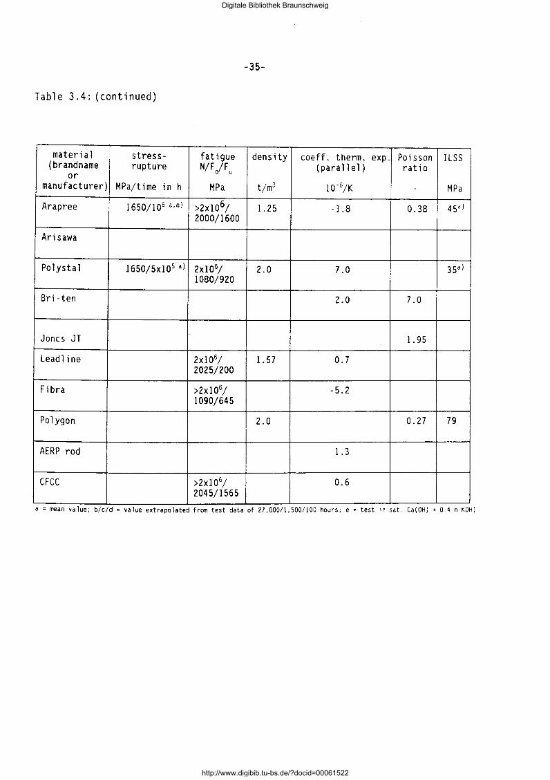
Table 3.4: (continued)
material stress- fatigue density coeff. therm. exp. Poisson ILSS (brandname rupture N/F jFu (parallel) ratio
or manufacturer) MPa/time in h MP a t/m3 10-6/K - MP a
Arapree 1650/106 a,e) >2x1o6; 1. 25 -1.8 0.38 45al 2000/1600
Arisawa
Polystal 1650/5x105 a) 2x10⁶/ 2.0 7.0 35al 1080/920
Bri-ten 2.0 7.0
Joncs JT 1. 95
Leadline 2x10⁶/ 1. 57 0.7 2025/200
Fibra >2x10⁶/ -5.2
1090/645
Polygon 2.0 0.27 79
AERP rod 1.3
CFCC >2x10 6/ 0.6
2045/1565 a= mean value; b/c/d =value extrapolated from test data of 27,000/1,500/100 hours; e = test 1n sat. Ca(OH) + 0 4 n KOH)
Digitale Bibliothek Braunschweig
http://www.digibib.tu-bs.de/?docid=00061522
-36-
3.5 Literature
[3.1] Oolan, c.w.: Developments in Non-Metallic Prestressing Tendons. ACI
Journal, Sept.-Okt. 1990, pp. 80/88.
[3.2] L K C Performance Eval uation of Glass and Fi-Iyer, S. . ; umaraswamy, . : ber Composite Cable for Prestressed Concrete Units. 33rd Int. SAMPE
Symp., Anaheim, March 1988, pp. 844/851.
[3.3] Kakihara, R.; Kamiyoshi, M.; Kumagi, S.; Noritake, K.: A New Aramid
Rod for the Reinforcement of Prestressed Concrete Structures. ASCE
Spec. Conf.: Advanced Composites Materials in Civil Engineering
Structures, Las Vegas, 1991, pp. 132/142.
[3.4] Les materiaux nouveaux pour la precontrainte et le renforcement
d'ouvrages d'art. Int. Symp. ENPC, Paris, Oct. 1988.
[3.5] MieBeler, H.-J.; Wolff, R.: Experience with the Monitoring of Struc
tures Using Optical Fiber Sensors. FIP-Xlth Int. Congress on Pre
stressed Concrete, Hamburg, June 1990, pp. Q 12/17.
[3.6] Mikami, H.; Katok, M.; Takeuchi, H.; Tamura, T.: Shear Behaviour of
Concrete Beams Reinforced with Braided High Strength Fiber Rods in
Spiral Shape. FIP-Xlth Int. Congress on Prestressed Concrete, Ham
burg, June 1990, pp. T 44/46.
[3. 7] Gerritse, A.; Maatjes, E.; Schurhoff, H.J.: Prestressed Concrete
Structures with High-Strength Fibers. IABSE Report Vol. 55, Zurich, 1987, pp. 425/432.
[3.8] Gerritse, A.; Schurhoff, H.J.; Maatjes, E.: Prestressed Concrete
Structures with Arapree; Relaxation. IABSE-Symp. Concrete Structures for the Future, Versailles, 1987.
[3.9] Reinhardt, H.W.; Gerritse, A.; Werner, J.: Arapree _ A New Prestres
sing Material is Going into Practice. FIP-XIth Int. Congress on Prestressed Concrete, Hamburg, June 1990, pp. T 66/69.
[3.10] Rostasy, F.S.: New Materials for Prestressing. FIP-Symp., Jerusalem/ Israel, Sept. 1988.
Digitale Bibliothek Braunschweig
http://www.digibib.tu-bs.de/?docid=00061522
-37-
[3.11] Rostasy, F.S.; Budelmann, H.: FRP-Tendons for the Post-Tensioning of
Concrete Structures. ASCE Spec. Conf.: Advanced Composites Materials
in Civil Engineering Structures, Las Vegas, 1991, pp. 155/166.
Digitale Bibliothek Braunschweig
http://www.digibib.tu-bs.de/?docid=00061522
-38-
4. STRENGTH AND DEFORMATION OF FRP
4.1 Scope
The design and structural detailing of r/c- and/or p/c-members, reinforced and/or prestressed with FRP tensile elements, requires adequate knowledge of
the mechanical properties of fiber composites. FRP are generally unfamiliar
materials to structural engineers, who are used to work primarily with iso
tropic or at least with quasi-isotropic materials. FRP are orthotropic. Their mechanical behaviour depends markedly on the state of stress and also on temperature, environment, strain history etc. The main features of the
mechanical behaviour will be described in the following sections.
4.2 Mechanical Behaviour Under Short-term Loading
4.2.1 Basic Relations
For the prediction of the properties and of the behaviour of a composite the so-called rule of mixtures often is a useful tool. Thereby the properties of the FRP are considered as the volume-weighted average properties of the com
ponents. In the rule of mixtures the following subscripts are used: f, m, c
and P denote fiber, matrix, composite and voids, respectively. The masses, volumes and densities of the components and of the composite are given by the following equations:
(4.la to 4.ld}
VC = vf + vm + vP
MC = Mf + Mm
These expressions can be normalized:
vf V m vP. vf , vm -· vv = , , (4.le} VC VC VC
Digitale Bibliothek Braunschweig
http://www.digibib.tu-bs.de/?docid=00061522
-39-
VC vf + vm + vv
Mf Mm mf M ' mm M ' mp 0
c c (4.2a to 4.2c)
Pf Pm me mf + mm vf +- vm
Pc Pc (4.2d)
The density of the composite can be expressed as follows:
(4.3)
4.2.2 Elastic Constants and Composite Stresses
In Fig. 4.la the ud-element is subjected to in-plane stresses. The composite
axial stress ac may be devived under the presupposition that the components and the composite will undergo an identical axial elastic strain [4.1]. With
the rule of mixtures we obtain:
(4.4)
The axial composite Youngs's modulus Ec and the Poisson's ratio ~c are:
( 4. 5)
(4.6)
The Eq.(4.4} to (4.6) presuppose the elastic behaviour in the fiber direction irrespective of the stress magnitude. For practical purposes this presupposition is justified for high-strength FRP because the contribution of
the fibers is far greater than of the matrix and because the fibers are ide
ally elastic. This fact is shown for the GFRP Polystal 0 7,5 mm bar in
Fig. 4.2.
For stresses acn acting perpendicular to the fiber axis the assumption acn =
am = of leads to the transverse modulus of elasticity of the composite (Fig.
4.lb):
Digitale Bibliothek Braunschweig
http://www.digibib.tu-bs.de/?docid=00061522
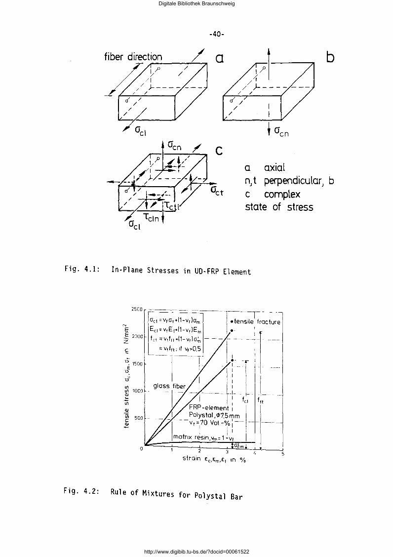
-40-
b
a axial nJ t perpendicular) b c complex state of stress
Fig. 4.1: In-Plane Stresses in UD-FRP Element
2 3 5
Fig. 4.2: Rule of Mixtures for Polystal Bar
Digitale Bibliothek Braunschweig
http://www.digibib.tu-bs.de/?docid=00061522
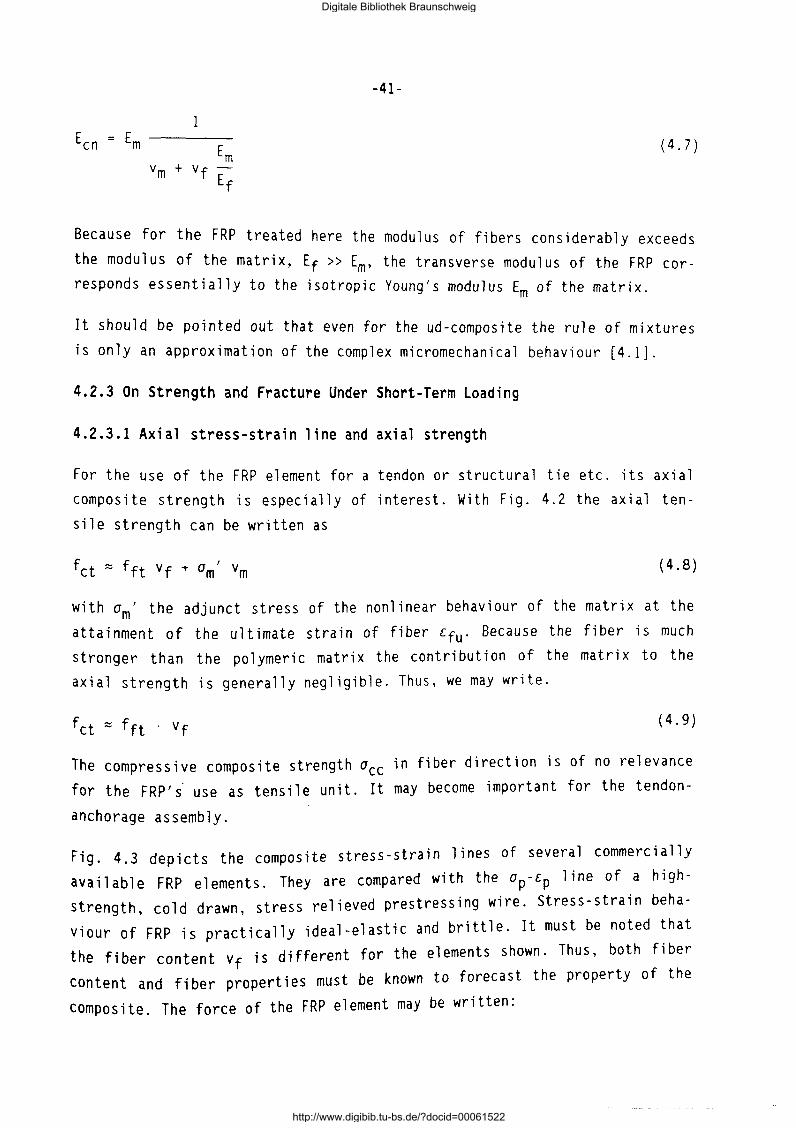
-41-
1 ( 4. 7)
Because for the FRP treated here the modulus of fibers considerably exceeds
the modulus of the matrix, Ef >> Em, the transverse modulus of the FRP corresponds essentially to the isotropic Young's modulus Em of the matrix.
It should be pointed out that even for the ud-composite the rule of mixtures is only an approximation of the complex micromechanical behaviour [4.1].
4.2.3 On Strength and Fracture Under Short-Term Loading
4.2.3.1 Axial stress-strain line and axial strength
For the use of the FRP element for a tendon or structural tie etc. its axial composite strength is especially of interest. With Fig. 4.2 the axial ten
sile strength can be written as
( 4. 8)
with am' the adjunct stress of the nonlinear behaviour of the matrix at the
attainment of the ultimate strain of fiber Efu· Because the fiber is much stronger than the polymeric matrix the contribution of the matrix to the
axial strength is generally negligible. Thus, we may write.
(4.9)
The compressive composite strength ace in fiber direction is of no relevance for the FRP' s· use as tensile unit. It may become important for the tendon-
anchorage assembly.
Fig. 4.3 depicts the composite stress-strain lines of several commercially
available FRP elements. They are compared with the ap-Ep line of a highstrength, cold drawn, stress relieved prestressing wire. Stress-strain beha
viour of FRP is practically ideal-elastic and brittle. It must be noted that
the fi ber content vf ; s different for the elements shown. Thus, both fi ber
content and fi ber properties must be known to forecast the property of the
composite. The force of the FRP element may be written:
Digitale Bibliothek Braunschweig
http://www.digibib.tu-bs.de/?docid=00061522
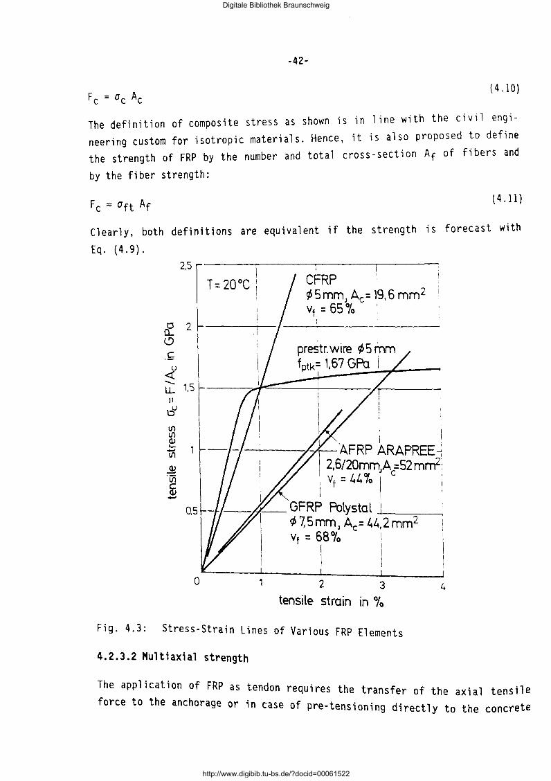
(4.10}
The definition of composite stress as shown is in line with the civil engineering custom for isotropic materials. Hence, it is also proposed to define the strength of FRP by the number and total cross- section At of fi bers and
by the fiber strength:
(4.11)
Clearly, both definitions are equivalent if the strength is forecast with
Eq. (4.9}. 2,5
£ 2 (.!)
.~ u
<( -LL 1,5 11
\:>u
Ul Ul ~ 'tii
1
CFRP tpSmmJ Ac= 19,6 mm2 1
vf = 65% I I
i prestr. wire tp 5 mm fptk= 1,67 GPa I
I
tensile strain in Ofo
Fig. 4.3: Stress-Strain Lines of Various FRP Elements
4.2.3.2 Multiaxial strength
The application of FRP as t d . f t th en on requlres the transfer of the axial tensile orce o e anchorage or in case of pre-tensioning directly to the concrete
Digitale Bibliothek Braunschweig
http://www.digibib.tu-bs.de/?docid=00061522
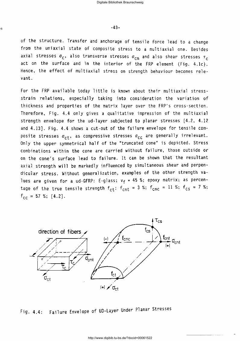
-43-
of the structure. Transfer and anchorage of tensile force lead to a change
from the uniaxial state of composite stress to a multiaxial one. Besides
axial stresses ac, also transverse stresses acn and also shear stresses re
act on the surface and ·in the interior of the FRP element (Fig. 4.1c).
Hence, the effect of multiaxial stress on strength behaviour becomes relevant.
For the FRP available today little is known about their multiaxial stress
strain relations, especially taking into consideration the variation of
thickness and properties of the matrix layer over the FRP's cross-section.
Therefore, Fig. 4.4 only gives a qualitative impression of the multiaxial
strength envelope for the ud-layer subjected to planar stresses [4.2, 4.12
and 4.13]. Fig. 4.4 shows a cut-out of the failure envelope for tensile com
posite stresses act, as compress i ve stresses ace are generally irrelevant.
Only the upper symmetrical half of the "truncated cone" is depicted. Stress
combinations within the cone are carried without failure, those outside or
on the cone's surface lead to failure. It can be shown that the resultant
axial strength will be markedly influenced by simultaneous shear and perpen
dicular stress. Without generalization, examples of the other strength va
lues are given for a ud-GFRP: E-glass; Vf = 45 %; epoxy matrix; as percen
tage of the true tensile strength fct= fcnt = 3 %; fcnc = 11 %; fcs = 7 %;
fee= 57%; [4.2].
direction of fibers
(+) / Oct
r· lg. 4.4: Failure Envelope of UD-Layer Under Planar Stresses
Digitale Bibliothek Braunschweig
http://www.digibib.tu-bs.de/?docid=00061522
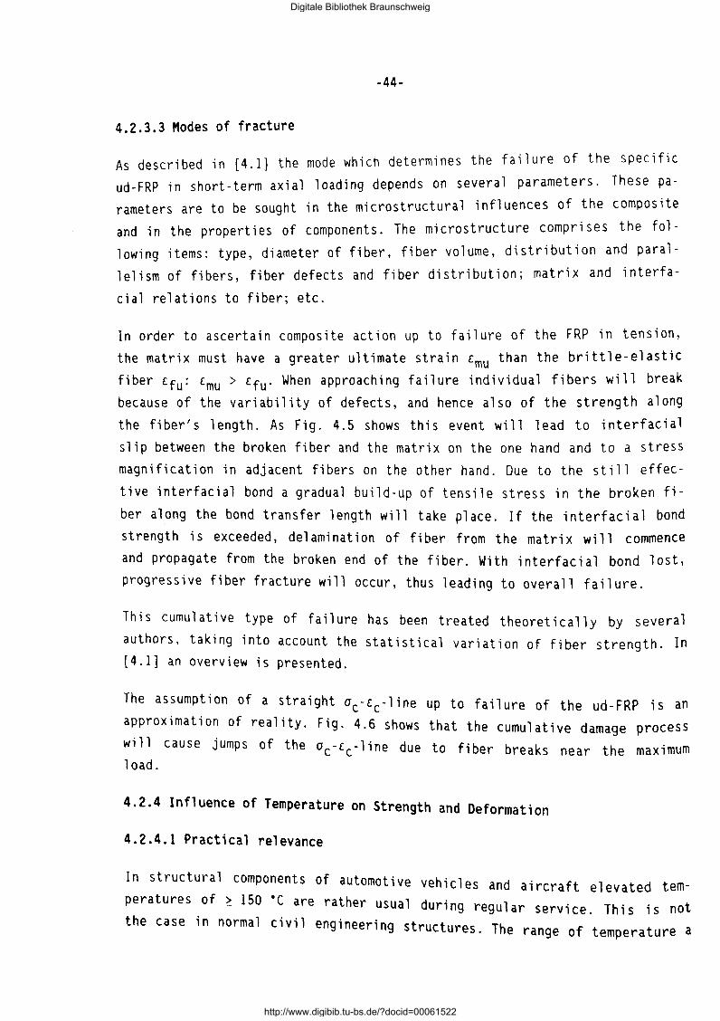
-44-
4.2.3.3 Modes of fracture
As described in [4.1] the mode which determines the failure of the specific
ud-FRP in short-term axial loading depends on several parameters. These parameters are to be sought in the microstructural influences of the composite
and in the properties of components. The microstructure comprises the fol
lowing items: type, diameter of fiber, fiber volume, distribution and paral
lelism of fibers, fiber defects and fiber distribution; matrix and interfa
cial relations to fiber; etc.
In order to ascertain composite action up to failure of the FRP in tension,
the matrix must have a greater ultimate strain emu than the brittle-elastic
fiber £fu: £mu > £fu· When approaching failure individual fibers will break because of the variability of defects, and hence also of the strength along
the fiber's length. As Fig. 4.5 shows this event will lead to interfacial
slip between the broken fiber and the matrix on the one hand and to a stress magnification in adjacent fibers on the other hand. Due to the still effec
tive interfacial bond a gradual build-up of tensile stress in the broken fi
ber along the bond transfer length will take place. If the interfacial bond strength is exceeded, delamination of fiber from the matrix will commence and propagate from the broken end of the fiber. With interfacial bond lost, progressive fiber fracture will occur, thus leading to overall failure.
This cumulative type of failure has been treated theoretically by several authors, taking into account the statistical variation of fiber strength. In [4.1] an overview is presented.
The assumption of a straight ac-£c-line up to failure of the ud-FRP is an approximation of reality. Fig. 4.6 shows that the cumulative damage process
will cause jumps of the ac-£c-line due to fiber breaks near the maximum load.
4.2.4 Influence of Temperature on Strength and Deformation
4.2.4.1 Practical relevance
In structural components of automotive vehicles and aircraft elevated temperatures of~ 150 ·care rather usual during regular service. This is not the case in normal civil engineering structures. The range of temperature a
Digitale Bibliothek Braunschweig
http://www.digibib.tu-bs.de/?docid=00061522
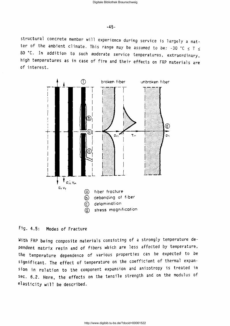
-45-
structural concrete member will experience during service ter of the ambient climate. This range may be assumed
is largely a matto be: -30 ·c $ T $
80 ·c. In addition to such d t · . mo era e serv1 ce temperatures, extraord; nary, high temperatures as n f f' 1 case o 1re and their effects on FRP materials are of interest.
r I I I I I I +· I I I I I I I l_
CD
I I
_L
broken fi ber
@ fiber fracture @ debonding of fi ber
© delamination @) stress magnification
Fig. 4.5: Modes of Fracture
unbroken f1 ber
w,· th FRP being composite materials consisting of a strongly temperature de-
pendent matrix resin and of fibers which are less affected by temperature,
the temperature dependence of various properties can be expected to be
significant. The effect of temperature on the coefficient of thermal expan
sion in relation to the component expansion and anisotropy is treated in
sec. 6. 2. Here, the effects on the tensile strength and on the modulus of
elasticity will be described.
Digitale Bibliothek Braunschweig
http://www.digibib.tu-bs.de/?docid=00061522
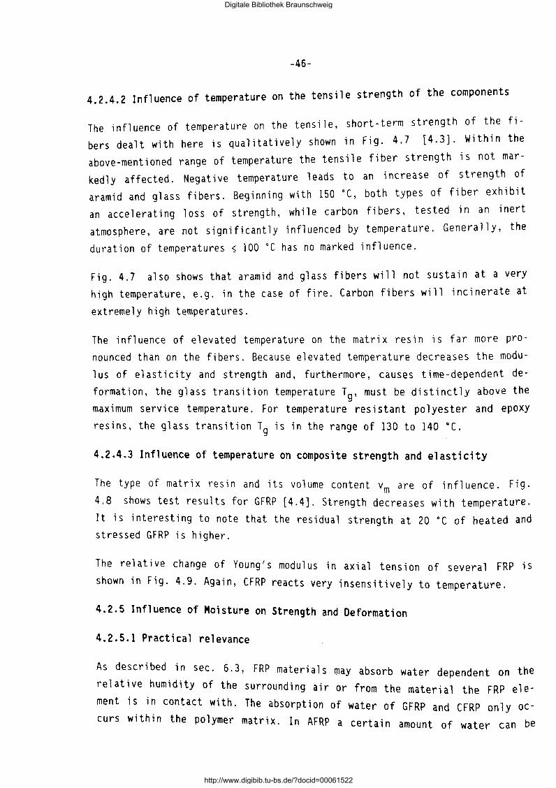
-46-
4.2.4.2 Influence of temperature on the tensile strength of the components
The influence of temperature on the tensile, short-term strength of the fi
bers dealt with here is qualitatively shown in Fig. 4.7 [4.3]. Within the
above-mentioned range of temperature the tensile fiber strength is not mar
kedly affected. Negative temperature leads to an increase of strength of
aramid and glass fibers. Beginning with 150 oc, both types of fiber exhibit
an accelerating loss of strength, while carbon fibers, tested in an inert
atmosphere, are not significantly influenced by temperature. GenerallY, the
duration of temperatures ~ 100 oc has no marked influence.
Fig. 4.7 also shows that aramid and glass fibers will not sustain at a very
high temperature, e.g. in the case of fire. Carbon fibers will incinerate at
extremely high temperatures.
The influence of elevated temperature on the matrix resin is far more pro
nounced than on the fibers. Because elevated temperature decreases the modu
lus of elasticity and strength and, furthermore, causes time-dependent de
formation, the glass transition temperature Tg, must be distinctly above the
maximum service temperature. For temperature resistant polyester and epoxy
resins, the glass transition Tg is in the range of 130 to 140 °(.
4.2.4.3 Influence of temperature on composite strength and elasticity
The type of matrix resin and its volume content vm are of influence. Fig.
4.8 shows test results for GFRP [4.4]. Strength decreases with temperature.
It is interesting to note that the residual strength at 20 oc of heated and stressed GFRP is higher.
The relative change of Young's modulus in axial tension of several FRP is
shown in Fig. 4.9. Again, CFRP reacts very insensitively to temperature.
4.2.5 Influence of Moisture on Strength and Deformation
4.2.5.1 Practical relevance
As described in sec· 6 · 3, FRP materia 1 s may absorb water dependent on the
relative humidity of the surrounding air or from the material the FRP ele
ment is in contact with. The absorption of water of GFRP and CFRP only oc
curs within the polymer matrix. In AFRP a certain amount of water can be
Digitale Bibliothek Braunschweig
http://www.digibib.tu-bs.de/?docid=00061522
3
2 d
0... L:l
c
c'"' ~ c d
b
0
Fig. 4.7:
GFRP; vf = 0,65 T = 20 °( , a1r E: = 0,4 %o/s
E- Glass fiber
' cumulative fiber fracture
ud- FRP Vf: 0,65
2 3
-47-
4
E:t and Ec in %
Fig. 4.6: Cumulative Damage
4r-----------------------
a 0... ~ 3 .£;
f-
-..::=- carbon HM
.c. 2 -+--O'l c ClJ c....
-+--t/)
~ 1 v;
c ClJ
-+--
E -glass fiber
00 200 400 600 800 1000 1200 temperature T in °(
Influence of Temperature on Fiber Strength
Digitale Bibliothek Braunschweig
http://www.digibib.tu-bs.de/?docid=00061522
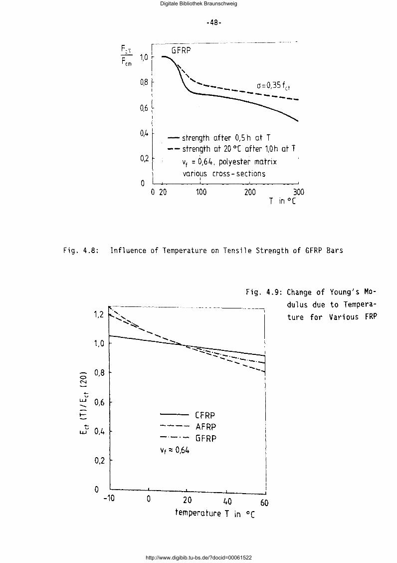
Fer Fern 1,0
0,8
0,6
0,4
0,2
0 0 20
-48-
GFRP
~
' ', .... _____ a::0,35 fet --------- .......
-strength after 0,5 h at T --strength at 20 °( after 1,0h at T ·
I I
vf = 0,64, polyester matrix
var1ous cross- sections I
100 200 300 T in °(
Fig. 4.8: Influence of Temperature on Tensile Strength of GFRP Bars
0 0,8
N
.... u
w 0,6 -r-+-u 0,4 w
0,2
0 -10 0
"""
Vt ~ 0,64
20
Fig. 4.9: Change of Young's Modulus due to Temperature for Various FRP
......._......:.c::::. ....... . ........ .................... -... ---·-·-
CFRP AFRP GFRP
40
---...
60 temperature T in °(
Digitale Bibliothek Braunschweig
http://www.digibib.tu-bs.de/?docid=00061522
-49-
absorbed by the aramid fiber. The absorption of water is a slow process ten
ding tow~rds t~e mean equilibrium moisture content meq which depends on the surround1ng cl1mate. Once meq is attained, e.g. after 1000 h, variation of moisture will be slow and small. For practical application, the equilibrium moisture content must be known because of its influence on strength and elasticity. It is important to note that the absorption of water and its influence on mechanical properties are entirely reversible processes.
4.2.5.2 Influence of moisture on composite behaviour
The effect of moisture on the strength and elasticity of FRP materials must be sought in the fact that moisture lowers the glass transition temperature Tg of the polymer matrix. Immediately after manufacture, the FRP element does not contain any evaporable water. It will then pick-up moisture during storage. Thus, for strength testing the moisture content must be known.
Taking the day of fabrication as reference time, the apparent decrease of strength in a defined climate vs. storage time can be established. For GFRP, vf ~ 0,68, a decrease of 4 to 6 % of the virgin strength was measured for a storage in a climate of 20 •cj65% r.h. (relative humidity). The Young's mo-
dulus will only be slightly affected.
4.2.6 Ageing due to Radiation
If FRP elements are exposed to solar radiation without protection and for a prolonged duration a significant loss of strength will occur. This loss of strength is caused primarily by ultraviolet radiation which, after an initial insignificant increase of strength due to supplementary crosslinkage in the matrix resin, reverts to degradation due to chain breaking. Degradation is enhanced by oxygen and moisture. Fig. 4.10 shows this degradation for several ud-FRP materials dependent on the accumulated ultraviolet radiation energy per cm2 surface area [4.3]. The degradation of GFRP is less pronounced than for AFRP and CFRP. This observation is not due to a special sensitivity of aramid and carbon fibers against radiation but to the greater therma 1 and hygroscopi c expansion i ncompat i bi 1 i ty between these fi bers and their matrix resin in contrast to glass fibers and the epoxy matrix. This mismatch may lead to microcracking in the matrix and to debonding. The
conclusion can be drawn that FRP must be shielded from ultraviolet light.
Digitale Bibliothek Braunschweig
http://www.digibib.tu-bs.de/?docid=00061522
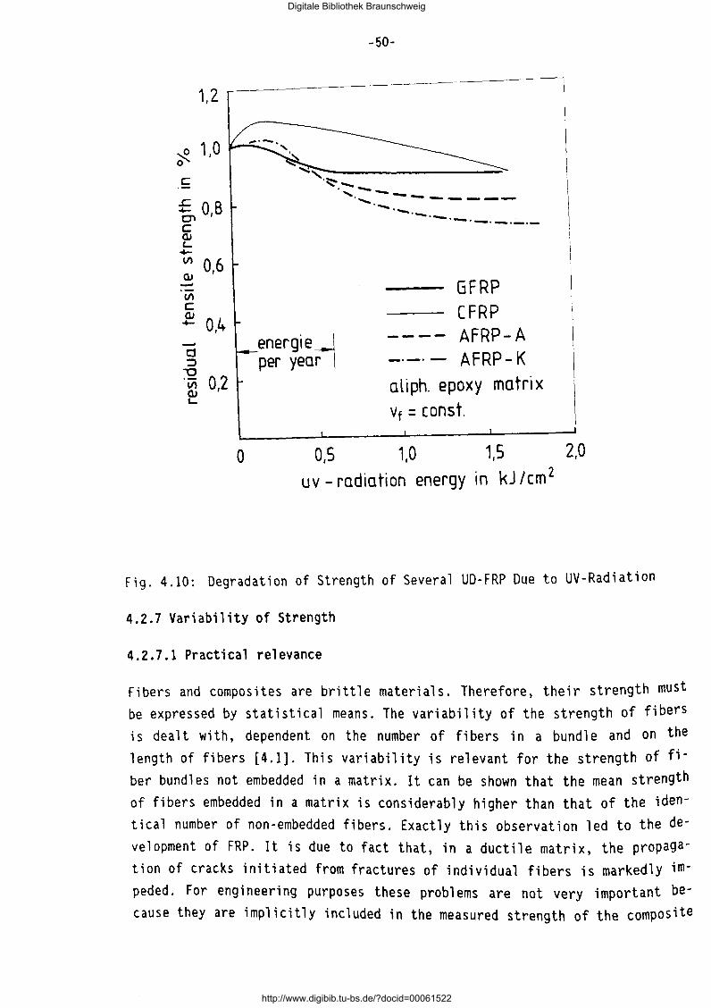
1,2
~ 1,0 0
c
£OB C'l' c QJ c...
-+-V) 0,6 OJ -V)
c OJ
0,4 -+-
-Cj ::J
""0 0,2 V)
OJ '-
-50-
~,~------------------~ ·~.--
energierl per year
...... --............. - ..... ___ ___ ................... ___ .......... __
·--·-·-·-
GFRP CFRP
---- AFRP-A -·-· - AFRP- K aliph. epoxy matrix vf = const.
0 0,5 1,0 1,5 2,0 uv- radiation energy in kJ /cm 2
Fig. 4.10: Degradation of Strength of Several UD-FRP Due to UV-Radiation
4.2.7 Variability of Strength
4.2.7.1 Practical relevance
Fibers and composites are brittle materials. Therefore, their strength must be expressed by statistical means. The variability of the strength of fibers ; s dealt with, dependent on the number of fi bers in a bundle and on the length of fibers [4.1]. This variability is relevant for the strength of fiber bundles not embedded in a matrix. It can be shown that the mean strength of fibers embedded in a matrix is considerably higher than that of the identical number of non-embedded fibers. Exactly this observation led to the development of FRP. It is due to fact that, in a ductile matrix, the propagation of cracks initiated from fractures of individual fibers is markedly impeded. For engineering purposes these problems are not very important because they are implicitly included in the measured strength of the composite
Digitale Bibliothek Braunschweig
http://www.digibib.tu-bs.de/?docid=00061522
-51-
element. Here the influence of the length and number of FRP elements on the strength of a tendon or tie is an important question which will be dealt with below.
4.2.7.2 Influence of length of FRP element on strength
The tensile strength of FRP elements of a certain cross-section Ac, fiber
content vf, etc. is tested with specimens of a certain length 10 . Statisti
cal evaluation of test results with a suitable probability density function
f(x 1), will lead to the cumulative probability of failure F1(x 1). With x1 the strength of the FRP element with the length 10 is notated. The strength
x1 is a scattering property.
A FRP element with a greater length, l > 10 , can be regarded as a chain of i links, with i = 1/1
0• For this chain the failure probability can be expres
sed by
(4.12)
The probability density function of the chain is the derivative of the fai
lure probability Eq.(4.12):
(4.13)
which must be known to express the effect of the length of the FRP element
on its strength. For the probability density function the so-called Weibull-
formulation can be chosen:
(4.14)
For the probability of failure we then obtain:
(4.15)
In the Eq.(4.14) which have to be
shown in [4.5].
and (4.15), m and xo are the so-called Weibull paramete~s . A 1 e of the procedure 1 s
determined expenmenta 11 Y. n ex amp
Digitale Bibliothek Braunschweig
http://www.digibib.tu-bs.de/?docid=00061522
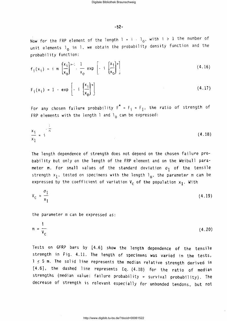
-52-
Now for the FRP element of the length = i . la, with i ~ 1 the number of
l · 1 we obta; n the probability density function and the unit elements 0 1n ,
probability function:
f;(x;) = i m l::t :0
exp [- (::]"] (4.16)
F;(x;) =I - exp [- [::rl (4.17)
For any chosen failure probability F* = F; = F1, the ratio of strength of
FRP elements with the length 1 and 10 can be expressed:
X· 1 m
(4.18)
The length dependence of strength does not depend on the chosen failure pro
bability but only on the length of the FRP element and on the Weibull para
meter m. For small values of the standard deviation a 1 of the tensile
strength x1, tested on specimens with the length 10 , the parameter m can be
expressed by the coefficient of variation Vc of the population x1. With
(4.19)
the parameter m can be expressed as:
l m "" (4.20)
Tests on GFRP bars by [4.6] show the length dependence of the tensile
strength in Fig. 4.11. The length of specimens was varied in the tests,
1 ~ 5 m. The solid line represents the median relative strength derived in
[4.6], the dashed line represents Eq. (4.18) for the ratio of median
strengths (median value: failure probability = survival probability). The
decrease of strength is relevant especially for unbonded tendons, but not
Digitale Bibliothek Braunschweig
http://www.digibib.tu-bs.de/?docid=00061522
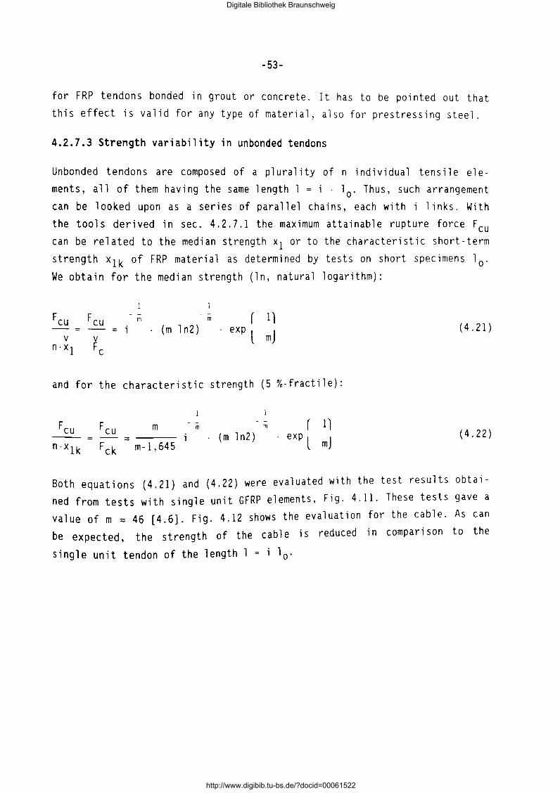
-53-
for FRP tendons bonded in grout or concrete. It has to be pointed out that this effect is valid for any type of material, also for prestressing steel.
4.2.7.3 Strength variability in unbonded tendons
Unbonded tendons are composed of a plurality of n individual tensile elements, all of them having the same length 1 = i · 1
0. Thus, such arrangement
can be looked upon as a series of parallel chains, each with i links. With
the tools derived in sec. 4.2.7.1 the maximum attainable rupture force Feu can be related to the median strength x1 or to the characteristic short-term
strength x1k of FRP material as determined by tests on short specimens 10 .
We obtain for the median strength (ln, natural logarithm):
Feu Feu - - - - r 1l m m
(m ln2) exp l mJ V V
n.x 1 Fe
(4.21)
and for the characteristic strength (5 %-tractile):
Feu Feu - - - - r 1) m m m
-- = - ::::: (m ln2) exp l mJ n·x1k Fck m-1,645 (4.22)
Both equations (4.21) and (4.22) were evaluated with the test results obtained from tests with single unit GFRP elements, Fig. 4.11. These tests gave a value of m ::::: 46 [4.6). Fig. 4.12 shows the evaluation for the cable. As can
be expected, the strength of the cable is reduced in comparison to the
single unit tendon of the length l = i 10 .
Digitale Bibliothek Braunschweig
http://www.digibib.tu-bs.de/?docid=00061522
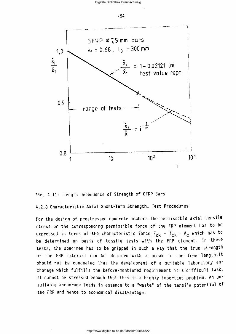
., X· I
1,0
0,9
0,8
-54-
------~--------------~
G FRP (/> 7,5 mm bars
vf = O, 68 , t 0 = 300 mm
., X· I = 1- 0,0 2121 lni
test value repr.
~-range of tests -:>~
1 10
., X· _, ., X
_.1_ I = j m
Fig. 4.11: Length Dependence of Strength of GFRP Bars
4.2.8 Characteristic Axial Short-Term Strength, Test Procedures
For the design of prestressed concrete members the permissible axial tensile stress or the corresponding permissible force of the FRP element has to be
expressed in terms of the characteristic force Fck = fck · Ac which has to be determined on basis of tensile tests with the FRP element. In these tests, the specimen has to be gripped in such a way that the true strength of the FRP material can be obtained with a break in the free length. It should not be concealed that the development of a suitable laboratory anchorage which fulfills the before-mentioned requirement is a difficult task. It cannot be stressed enough that this is a highly important problem. An unsuitable anchorage leads in essence to a "waste" of the tensile potential of the FRP and hence to economical disatvantage.
Digitale Bibliothek Braunschweig
http://www.digibib.tu-bs.de/?docid=00061522
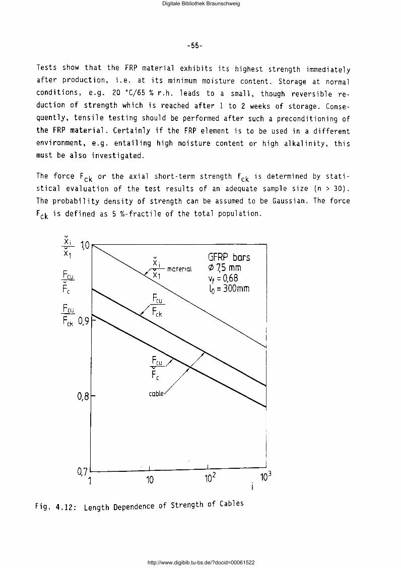
-55-
Tests show that the FRP material exhibits its highest strength immediately after production, i.e. at its minimum moisture content. Storage at normal conditions, e.g. 20 oC/65% r.h. leads to a small, though reversible reduction of strength which is reached after 1 to 2 weeks of storage. Consequently, tensile testing should be performed after such a preconditioning of the FRP material. Certainly if the FRP element is to be used in a different environment, e.g. entailing high moisture content or high alkalinity, this must be also investigated.
The force Fck or the axial short-term strength fck is determined by statistical evaluation of the test results of an adequate sample size (n > 30). The probability density of strength can be assumed to be Gaussian. The force Fck is defined as 5 %-fractile of the total population.
V
__&_ 1 0 re-------------------, V I
x1
Feu Fck 0, 9
0,8 cable
mater1al
GFRP bars C/J 7,5 mm Vf = 0,68 ~ = 300mm
Fig. 4.12: Length Dependence of Strength of Cables
Digitale Bibliothek Braunschweig
http://www.digibib.tu-bs.de/?docid=00061522
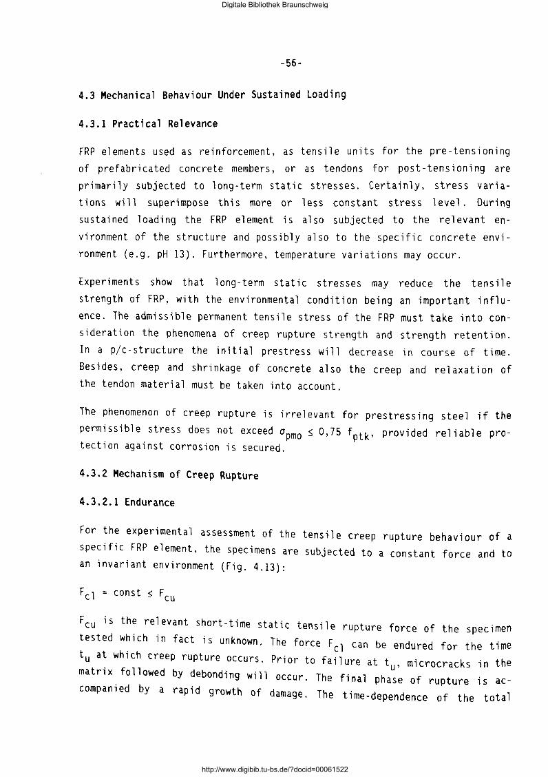
-56-
4.3 Mechanical Behaviour Under Sustained Loading
4.3.1 Practical Relevance
FRP elements used as reinforcement, as tensile units for the pre-tensioning
of prefabricated concrete members, or as tendons for post- tension i ng are
primarily subjected to long-term static stresses. Certainly, stress varia
tions will superimpose this more or less constant stress level. During
sustained loading the FRP element is also subjected to the relevant en
vironment of the structure and possibly also to the specific concrete envi
ronment (e.g. pH 13). Furthermore, temperature variations may occur.
Experiments show that long-term static stresses may reduce the tensile
strength of FRP, with the environmental condition being an important influ
ence. The admissible permanent tensile stress of the FRP must take into con
si deration the phenomena of creep rupture strength and strength retention.
In a plc-structure the initial prestress will decrease in course of time.
Besides, creep and shrinkage of concrete also the creep and relaxation of the tendon material must be taken into account.
The phenomenon of creep rupture is irrelevant for prestressing steel if the
permissible stress does not exceed apmo $ 0,75 fptk' provided reliable protection against corrosion is secured.
4.3.2 Mechanism of Creep Rupture
4.3.2.1 Endurance
For the experimental assessment of the tensile creep rupture behaviour of a specific FRP element, the specimens are subjected to a constant force and to an invariant environment (Fig. 4.13):
Feu is the relevant short-time static tensile rupture force of the specimen
tested which in fact is unknown. The force Fcl can be endured for the time
tu a~ which creep rupture occurs. Prior to failure at tu, microcracks in the matnx followed by debonding will occur. The final phase of rupture is accompanied by a rapid growth of damage. The time-dependence of the total
Digitale Bibliothek Braunschweig
http://www.digibib.tu-bs.de/?docid=00061522
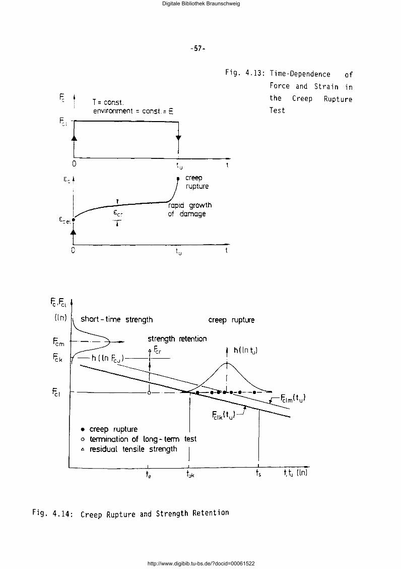
F,:
~: f 0
Ed
I I I I
'"t
~·~{ (ln)
0
-57-
Fig. 4.13:
T = const. enwonment = const. = E
t tu
creep rupture
' rapid growth Ecr of damage ~.
tu
short- time strength
strength retention
-r~
• creep rupture o termination of long- term test A residual tensile strength
-t
creep rupture
Fig. 4.14: Creep Rupture and Strength Retention
Time-Dependence of Force and Strain in the Creep Rupture Test
t, tu (ln)
Digitale Bibliothek Braunschweig
http://www.digibib.tu-bs.de/?docid=00061522
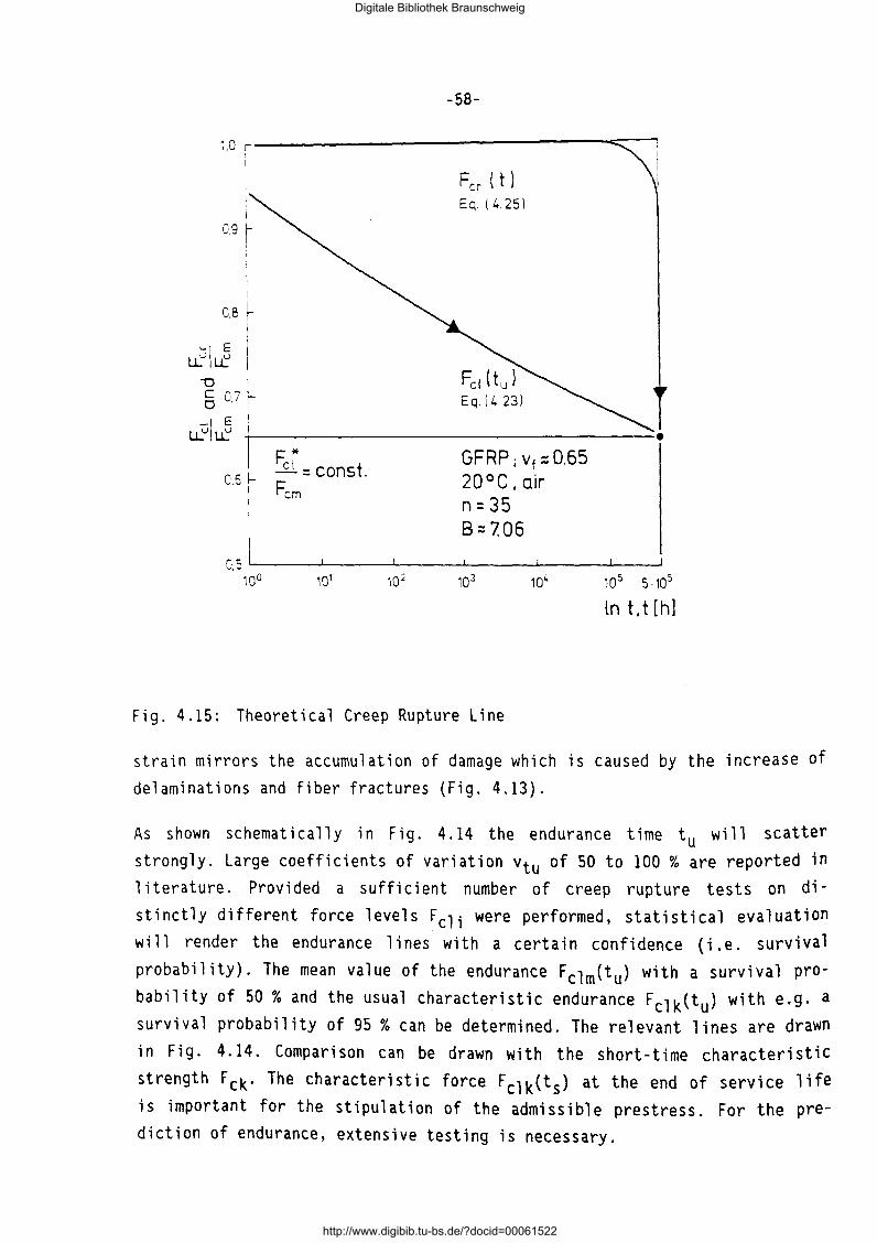
-58-
~.0 r-----------------=::::;::-1
0.9
I I
i I
i
OB~ I
u.~IJ I -o I § 0,7 r
Fer ( t } Eq. ( L. 251
u.uiJ r~------------------------------1
0.5
F.* ....£l = const. Fe m
GFRP; vf::: 0.65 20°C,air n = 35 8:::7.06
0.5 t__ __ __._ __ ~-----"---.J-_----L------.J
100 10~ 10 5 5·105
lnt.t[h]
Fig. 4.15: Theoretical Creep Rupture Line
strain mirrors the accumulation of damage which is caused by the increase of delaminations and fiber fractures (Fig. 4.13).
As shown schematically in Fig. 4.14 the endurance time tu will scatter strongly. Large coefficients of variation Vtu of 50 to 100 % are reported in 1 iterature. Provided a sufficient number of creep rupture tests on distinctly different force levels Fcli were performed, statistical evaluation will render the endurance lines with a certain confidence (i.e. survival probability). The mean value of the endurance Fclm<tu) with a survival probability of 50% and the usual characteristic endurance Fclk(tu) with e.g. a survival probability of 95% can be determined. The relevant lines are drawn in Fig. 4.14. Comparison can be drawn with the short-time characteristic strength Fck· The characteristic force Fclk(t 5 ) at the end of service life is important for the stipulation of the admissible prestress. For the prediction of endurance, extensive testing is necessary.
Digitale Bibliothek Braunschweig
http://www.digibib.tu-bs.de/?docid=00061522
-59-
For the evaluation of the tests and, expecially, for the prediction of the endurance for the duration of service life, theoretical models are valuable.
By applications of the fracture mechanics concept for the time- and stressdependent growth of damage, the following equation for the endurance is given in [ 4. 7] :
,
Fcl (Btu) [ B :~] ;
n
F cu (4.23)
or with l n the natura 1 1 ogari thm:
[~] 1
I r"J ln - - ln B - - ln -Feu n n t 0
(4.24)
with t 0 = 1 h, tu in hours; B is a flaw size parameter relevant for the described material and element; n is a material parameter. Both, B and n, must
be derived on basis of tests. Eq.(4.24) represents a straight line in a double-ln plot. Fig. 4.15 shows the evaluation of Eq.(4.24) for a set of mate
rial parameters 8 and n, which were derived from tests with GFRP bars [4.6].
The creep rupture force Fcl is related to the mean tensile short-time
strength Fern· The example shows that a permanent force of 0.65 Fern would
lead to failure after about 5·105 hours of loading.
Fig. 4.16 shows test results for GFRP bars, tested in air of 20oC/65% r.h. The mean curves and the range of scatter of test results are drawn [4.4]. In
Fig. 4.17 test results of ARAPREE flat strips subjected to alkaline solution
in order to simulate the effect of concrete pore water are depicted [4.12).
Both the mean creep rupture line and the one with a survival probability of
95% were evaluated and drawn according to Eq.(4.23). AFRP are less sensitive to alkaline solutions than GFRP. CFRP are not significantly affected at
all by the latter.
4.3.2.2 Strength retention
Creep rupture entails a cumulative damage in course of time, commencing some
time prior to final failure. For the ultimate limit state design the origi
nal tensile strength of the FRP be available during service life ts without
any significant loss.
Digitale Bibliothek Braunschweig
http://www.digibib.tu-bs.de/?docid=00061522
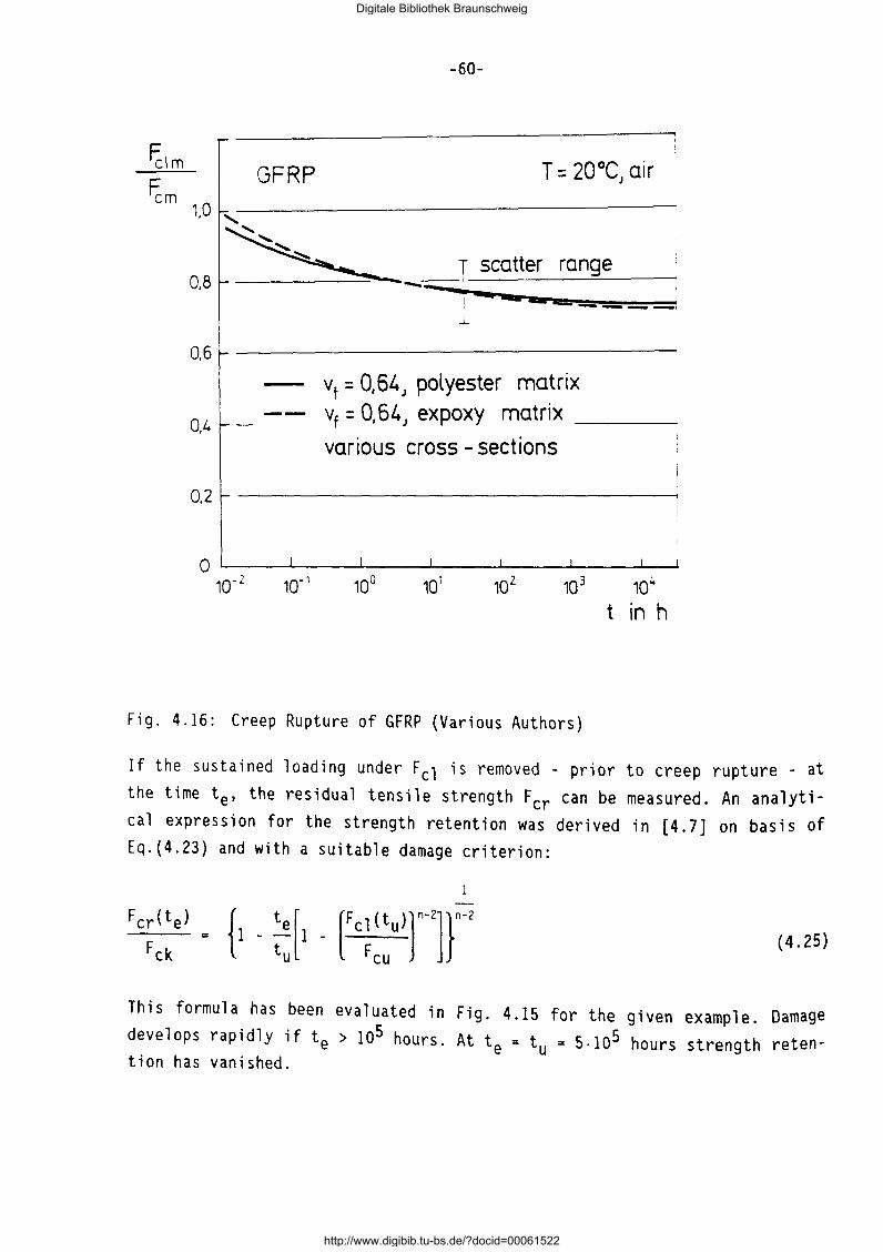
~lm ~m
-60-
GFRP 1,0
~ __ T ____ ____::=::: __ _ _ ~ scatter range 0,8 ---~· ............ _...==-=~~~ 1 ---==----· 0,6
O,L.
0,2
vt = 0,64J polyester matrix vt = 0, 64 J expoxy matrix
various cross- sections
0 L---~-----L----~----~----~----~~ 10-2 10-1 10° 101 102 103 104
t in h
Fig. 4.16: Creep Rupture of GFRP (Various Authors)
If the sustained loading under Fcl is removed - prior to creep rupture - at the time te, the residual tensile strength Fer can be measured. An analytical expression for the strength retention was derived in [4.7] on basis of Eq.(4.23) and with a suitable damage criterion:
(4.25)
This formula has been evaluated in Fig. 4.15 for the given example. Damage develops rapidly if te > 105 hours. At te =tu= 5·105 hours strength retention has vanished.
Digitale Bibliothek Braunschweig
http://www.digibib.tu-bs.de/?docid=00061522
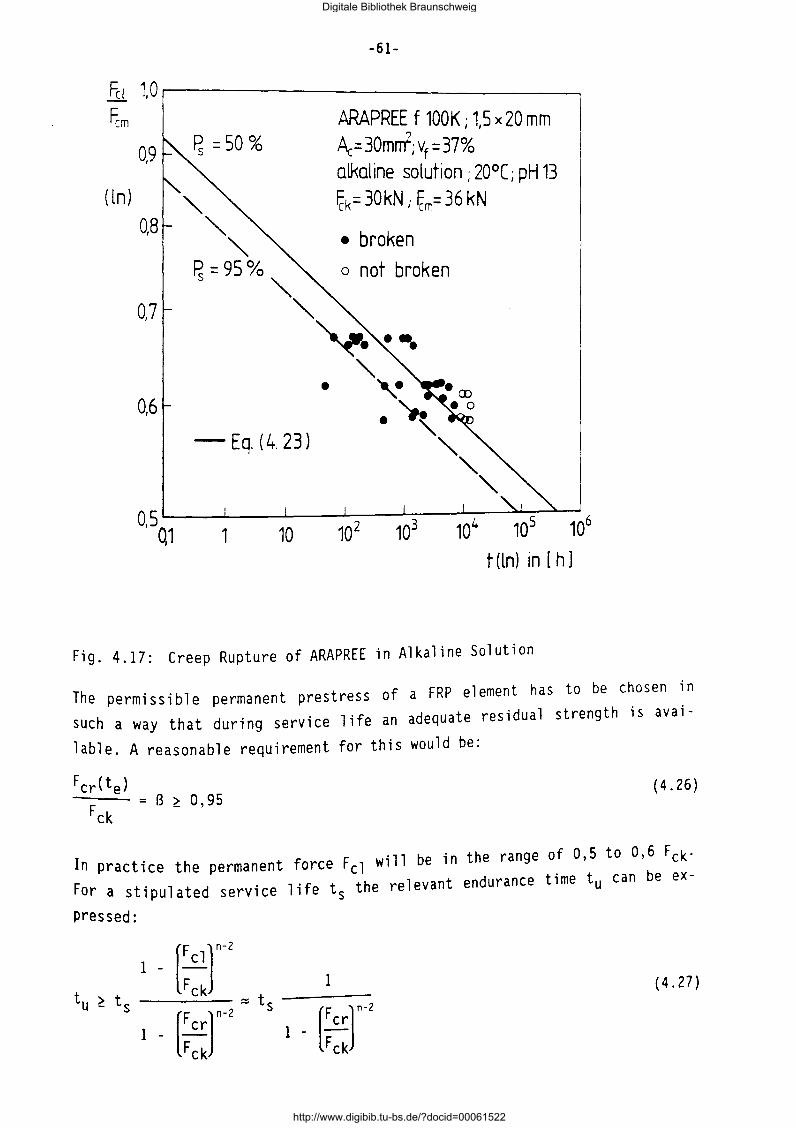
-61-
fu 1.01-------------~ fcm
( ln)
0,9
0,8
0,7
0,6
- Eq. (4. 23)
•
ARAPREE f 100K; 1,5 x 20 mm Ac= 30mrrt; vf = 37% alkaline solution; 20°[; pH 13 fck= 30kN; fcm= 36 kN
• broken o not broken
0,5 ~-....l-.--....L.----L--__j_-_L_~~_J Q1 1 10 102 103 104 10
5 10
6
t (ln) in [ h]
Fig. 4.17: Creep Rupture of ARAPREE in Alkaline Solution
The permissible permanent prestress of a FRP element has to be chosen in such a way that during service life an adequate residual strength is avai-
lable. A reasonable requirement for this would be:
Fcr(te) = B ~ 0,95
(4.26)
In practice the permanent force Fcl will be in the range of 0,5 to 0,6 Fck· For a stipulated service life ts the relevant endurance time tu can be ex-
pressed:
I - [Fclr tu ~ ts
Fck 1 ( 4. 27)
[Fcrr' = t, [Fcrr' 1 - 1 -Fck F ck
Digitale Bibliothek Braunschweig
http://www.digibib.tu-bs.de/?docid=00061522
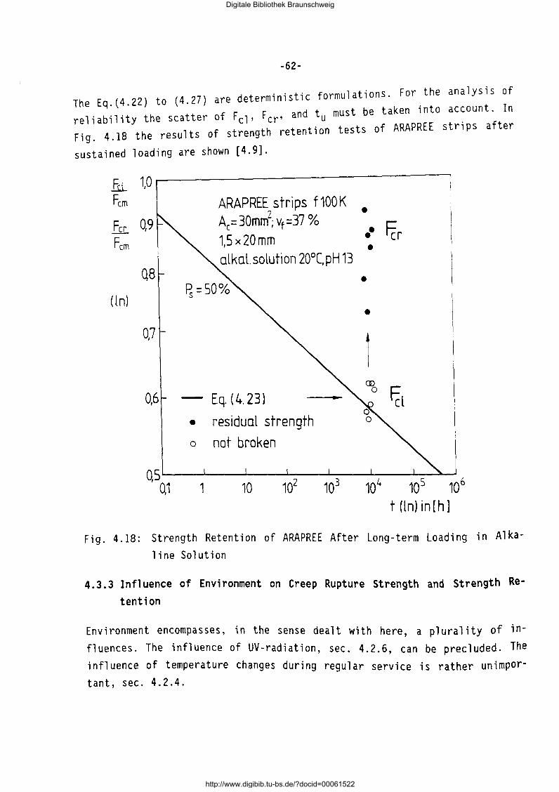
-62-
· · · f 1 t'ons For the analysis of The Eq.(4.22) to (4.27) are determ1n1st1c ormu a 1 ·
d t must be taken into account. In rel; ability the scatter of F cl' Fer' an u . Fig. 4.18 the results of strength retention tests of ARAPREE stnps after
sustained loading are shown [4.9].
fu_ Fern
Fer Fern
( lnl
1,0
0,9
0,7
0,6
ARAPREE strips f 100 K Ae= 30mm2
; Vt =37 % 1,5x20mm alkal.solution 20°C,pH 13
Eq.(4.23l
• residual strength
o not broken
• •• Fcr •
•
•
1 ~ r:
'cl
Qs~--~--~--~-2--~-3--~4--~-5~~6 0,1 1 10 10 10 10 10 10
t(ln)in[h]
Fig. 4.18: Strength Retention of ARAPREE After Long-term Loading in Alka
line Solution
4. 3. 3 Influence of Environment on Creep Rupture Strength and Strength Re
tention
Environment encompasses, in the sense dealt with here, a plurality of in
fluences. The influence of UV-radiation, sec. 4.2.6, can be precluded. The
influence of temperature changes during regular service is rather unimpor
tant, sec. 4.2.4.
Digitale Bibliothek Braunschweig
http://www.digibib.tu-bs.de/?docid=00061522
-63-
The uptake of moisture reduces the short-term tensile strength of FRP only a
little. It can be assumed that it will also reduce the creep rupture strength in the same magnitude.
The FRP dealt with here will not be damaged by ions from acidic solutions,
such as chlorides. More important is the influence of alkaline solutions
with pH 12, 5 and higher: fresh concrete and the pore so 1 uti on of hardened
concrete. As the alkaline solution penetrates through the matrix to the fi
bers, it will adversely affect both the short-term and the long-term
strength of glass and aramid fibers. This effect is of a stress corrosion
type. Tests show that E-glass fibers are more severely attacked than S-glass
fibers. If the matrix consists of epoxy resin, attack is diminished in com
parison to a polyester matrix. Inhibitors, added to the matrix, will improve
the long-term strength [4.8]. Though research shows promising ways to in
crease the long-term strength of GFRP, the latter have presently to be pro
tected from contact with high alkaline solution.
Aramid fibers in epoxy matrix are less affected by high alkaline solution.
Extensive tests have been performed to assess the creep rupture and strength
retention of ARAPREE in cementitious solutions [4.9]. It was shown that by
raising the temperature of the solution from 2o·c to 6o·c the prediction of
behaviour at 2o•c can be extrapolated for long duration (time factor 100;
i.e. two decades). By testing the FRP-element in grout or cementitious solu
tion the weakening effect of moisture is simultaneously incorporated.
CFRP are the least sensitive FRP materials to any kind of environmental in
fluence.
4.3.4 Characteristic Long-Term Strength
4.3.4.1 Necessary test work
On basis of short-term static tensile tests the characteristic short-term
strength Fck has been determined, sec. 4.2.8. Creep rupture behaviour must
be investigated on at least three distinctly different force levels Fcli•
e.g.: 0,8; 0,7; and 0,6 Fck; Fig. 4.14. The force Fcli is maintained con
stant until break occurs the fracture times tu; are being recorded· 1 f the
FRP element is to be use~ in practice in a detrimental environment then this
has also to be considered in the tests, e.g.: cementitious, high alkaline
Digitale Bibliothek Braunschweig
http://www.digibib.tu-bs.de/?docid=00061522
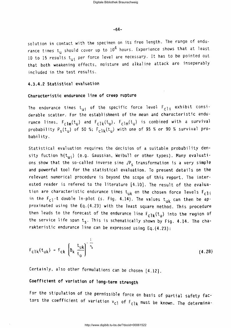
-64-
solution in contact with the specimen on its free length. The range of endurance times t should cover up to 104 hours. Experience shows that at least 10 to 15 resu~ts tu; per force level are necessary. It has to be pointed out that both weakening effects, moisture and alkaline attack are inseperably
included in the test results.
4.3.4.2 Statistical evaluation
Characteristic endurance line of creep rupture
The endurance times tu; of the specific force level Fcli exhibit considerable scatter. For the establishment of the mean and characteristic endu
rance lines, Fclm(tu) and Fclk(tu), Fclm(tu) is combined with a survival probability Ps(tu) of 50%; Fclk(tu) with one of 95% or 90% survival probability.
Statistical evaluation requires the decision of a suitable probability density fuction h(tui) (e.g. Gaussian, Weibull or other types). Many evaluations show that the so-called inverse sine jPs transformation is a very simple and powerful tool for the statistical evaluation. To present details on the relevant numerical procedure is beyond the scope of this report. The interested reader is refered to the literature [4.10]. The result of the evaluation are characteristic endurance times tuk on the chosen force levels Fcli in the Fc 1-t double ln-plot (s. Fig. 4.14). The values tuk can then be approximated using the Eq.(4.23) with the least square method. This procedure
then leads to the forecast of the endurance line Fclk(tu) into the region of the service life span ts. This is schematically shown by Fig. 4.14. The charakteristic endurance line can be expressed using Eq.(4.23):
(4.28)
Certainly, also other formulations can be chosen [4.12].
Coefficient of variation of long-term strength
For the stipulation of the permissible force on basis of partial safety fac
tors the coefficient of variation vel of Fclk must be known. The determina-
Digitale Bibliothek Braunschweig
http://www.digibib.tu-bs.de/?docid=00061522

-65-
tion of the latter proves to be difficult. Hence, an approximative method for this will be presented in the sequel .
In Fig. 4.19 schematically the mean and the characteristic endurance line are shown. From the statistical evaluation the characteristic endurance time tuk and its standard deviation have been found. The endurance tuk can be expressed - assuming a ln-normal distribution - by the mean value turn of the endurance:
(4.29)
with vt the COV of the endurance time and with k the factor of the t-distri
bution.
fIn)
Fctm F- Eq. (4 30)
ck
Fclk -F Eq. ( 4.31)
ck
Fctm -- at tum --~ --~
Fck
at 1um
tuk tum t; tuk ;tum (In)
Fig. 4.19: Relation Between Mean and Characteristic Fc1-Line
If we assume, as parallel to each Eq.(4.23):
that the lines Fclk(tuk) and Fclm(tum) are shown by tests, other in double-ln-plot, both of them can be expressed with
(4.30)
Digitale Bibliothek Braunschweig
http://www.digibib.tu-bs.de/?docid=00061522
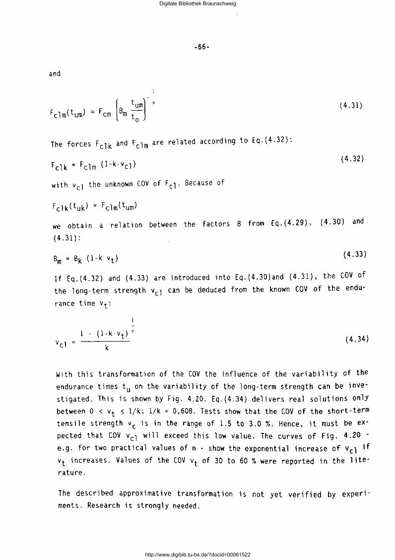
-66-
and
(4.31)
The forces Fclk and Fclm are related according to Eq.(4.32):
(4.32)
with vel the unknown COV of Fcl. Because of
Fclk(tuk) = Fclm(tum)
we obtain a relation between the factors B from Eq.(4.29), (4.30) and
(4.31):
Bm = Bk (1-k vt) {4.33)
If Eq.(4.32) and (4.33) are introduced into Eq.(4.30)and (4.31), the COV of the long-term strength vel can be deduced from the known COV of the endu-
{4.34)
With this transformation of the COV the influence of the variability of the endurance times tu on the variability of the long-term strength can be investigated. This is shown by Fig. 4.20. Eq.(4.34) delivers real solutions only between 0 ~ vt ~ 1/k; 1/k = 0,608. Tests show that the COV of the short-term tensile strength vc is in the range of 1.5 to 3.0 %. Hence, it must be expected that COV vel will exceed this low value. The curves of Fig. 4.20 -e.g. for two practical values of n - show the exponential increase of vel if vt increases. Values of the COV vt of 30 to 60% were reported in the literature.
The described approximative transformation is not yet verified by experiments. Research is strongly needed.
Digitale Bibliothek Braunschweig
http://www.digibib.tu-bs.de/?docid=00061522
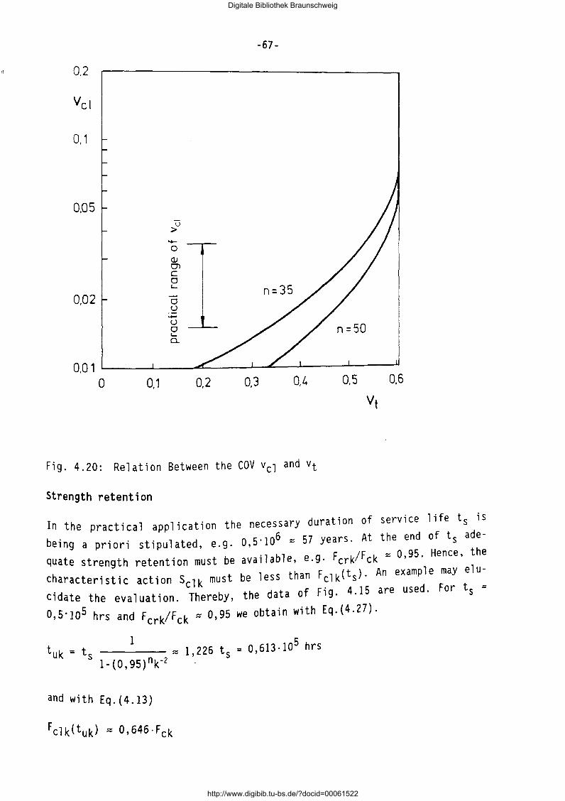
"
-67-
0.2
0,1
0,05 u
> -0 Q) CJ') c 0 '- n=35
0,02 0 u -u 0 '-0..
0.0 1 0 0,1 0,2 0,3 0,4
Fig. 4.20: Relation Between the COV vel and vt
Strength retention
0,5 0,6
Vt
In the pract i ea l a pp 1 i cation the necessary duration of service life ts is
being a priori stipulated, e.g. o,s·1o6 ::::: 57 years. At the end of ts ade
quate strength retention must be available, e.g. Fcrk/Fck ::::: 0,95. Hence, the
characteristic action sclk must be less than Fclk(ts)· An example may elu
cidate the evaluation. Thereby, the data of Fig. 4.15 are used. For t 5 =
O,S·1o5 hrs and Fcrk/Fck::::: 0,95 we obtain with Eq.(4.27).
1 tuk = t
5 ::::: 1,226 ts = 0,613·10
5 hrs
1-(0,95)nk-2
and with Eq.(4.13)
Fclk(tuk) ::::: 0,646·Fck
Digitale Bibliothek Braunschweig
http://www.digibib.tu-bs.de/?docid=00061522
-68-
5 Thus, if a constant action sclk is assumed to act, then at t 5 = 0.5·10 hrs the FRP element will still survive and have a strength retention of 0,95. Deliberations of this kind may serve as basis for the development of the de-
sign resistance.
4.3.5 Relaxation
For the estimation of the loss of prestress in course of time the stress relaxation of the tensile element must be known. The relaxation behaviour of the FRP elements treated here differs widely. The polymer matrix resins are visco-elastic materials, thus exhibiting relaxation. Glass fibers and carbon fibers show practically no relaxation. In contrast to these fibers, aramid fibers exhibit relaxation losses which increase with the decrease of the axial Young's modulus.
Of great influence on the magnitude of the relaxation loss is the environment the stressed FRP element is subjected to. An increase of temperature activates the relaxation, especially of the stresses imparted to the matrix. Hence, the relaxation 1 osses increase the more the 1 ower the fi ber vo 1 ume
vf.
In Fig. 4.21 the relaxation losses of GFRP bars (Polystal) and AFRP strips (ARAPREE) are depicted, with the specimens being stored in air of 20°C and 65% r.h. during the tests. Duration of tests was about 1000 to 3000 hours. For the sake of comparison the mean relaxation losses of a high-strength prestressing steel wire (cold drawn, stabilized, low relaxation type) are included [4.9, 4.13 to 4.15]. For initial stresses a· < 0 6 f lk the loss of
1 - ' c stress for FRP is independent on the initial stress. The relaxation loss of the GFRP elements is only slightly higher than of prestressing steel wire. In contrast to this, the relaxation loss of the ARAPREE elements (Twaron HM fibers) is considerably higher.
If the FRP element is to be used for the pre-tensioning of concrete members or if it is embedded in cementitious grout, its relaxation in the alkaline environment of moist, non-carbonated concrete must be known. In Fig. 4.22 the relaxation of AFRP rods, 0 8 mm (Twaron) and of CFRP rods, 0 8 mm is depicted [4.16]. During the tests the bars were subjected to a high-alkaline solution of pH 13 which was heated to 60°C. Such severe test conditions are
Digitale Bibliothek Braunschweig
http://www.digibib.tu-bs.de/?docid=00061522
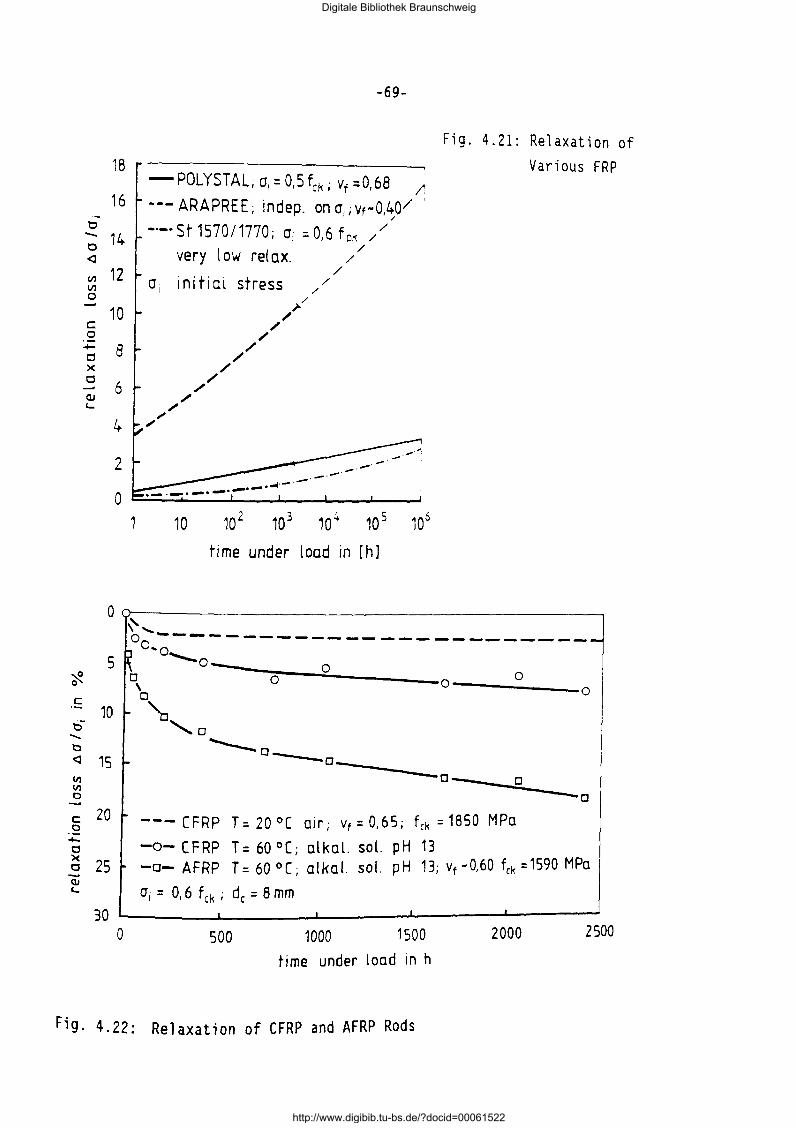
18
16 ·-
t:l - 14 t:l <l
VI 12 VI 0
10 c 0 - 8 Cl X Cl
6 (]J
'-
4
2
0 1
-69-
-POLYSTAL; cr,=O,Sfcki Yt=0,68 ;:
--- ARAPRE E; indep. on cr,; Vt-O,~Q/ -·-·St1570/1770; cri =0,6 fpk //
very low relax. / / /
cri initial stress // //'/
/ /
// /
/ /
/ /
.,-"
-· 10 10 2 10 3 10 4 10 5 106
time under load in [h]
Fig. 4.21: Relaxation of Various FRP
0 Q-------------------------------------------~
"
....... t::l
5
10
<l 15 VI VI 0
c: 20 0 -0
~ 25
0 '-----------o ... o ---------------......__0 ob -----cor---~o~---------------o----------0-----o
'o,D ...___o_ ~~
o---_;o~--o
--- CFRP T = 20 °[ 01r; Vt = 0,65; fck = 1850 MPo
-o- CFRP T= 60 °(; olkol. sol. pH 13 -a- AFRP T = 60 ° (; ol ko I. so!. pH 13; Yt • 0,60 fck = 1590 MPo
cr, = 0,6 fck; de= 8mm
30 ~------~------~------~----~~----~ 0 500 1000 1500 2000 2500
time under load in h
Fig. 4.22: Relaxation of CFRP and AFRP Rods
Digitale Bibliothek Braunschweig
http://www.digibib.tu-bs.de/?docid=00061522
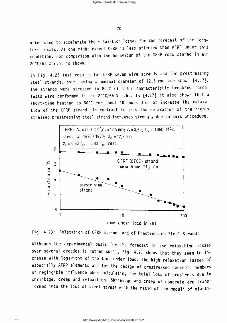
~70~
often used to accelerate the relaxation losses for the forecast of the longterm losses. As one might expect CFRP is less affected than AFRP under this condition. For comparison also the behaviour of the CFRP rods stared in air
20°C/65 % r.h. is shown.
In Fig. 4.23 test results for CFRP seven wire strands and for prestressing steel strands, both having a nominal diameter of 12,5 mm, are shown [4.17]. The strands were stressed to 80% of their characteristic breaking force. Tests were performed in air 20°C/65% r.h .. In [4.17] it also shown that a short-time heating to 60°C for about 10 hours did not increase the relaxation of the CFRP strand. In contrast to this the relaxation of the highly stressed prestressing steel strand increased strongly due to this procedure.
CFRP: Ac =76,3 mm2,dc =12,5mm; Vf =0,60; fck = 1860 MPa
steel: St 1670 /1870; dp = 12,5 mm
01 = 0,80 fck; 0,80 fpk resp.
Fig. 4.23: Relaxation of CFRP Strands and of Prestressing Steel Strands
Although the experimental basis for the forecast of the relaxation losses over several decades is rather small, Fig. 4.21 shows that they seem to increase with logarithm of the time under load. The high relaxation losses of especially AFRP elements are for the design of prestressed concrete members of negligible influence when calculating the total 1 f due to . oss o prestress shr1nkage, creep and relaxation. Shrinkage and f creep o concrete are trans-formed into the loss of steel stress with the ratio of the moduli of elasti-
Digitale Bibliothek Braunschweig
http://www.digibib.tu-bs.de/?docid=00061522
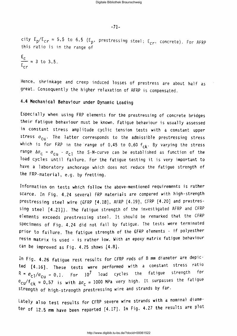
-71-
city Ep/Ecr z 5,5 to 6,5 (Ep, prestressing steel; Ecr' concrete). For AFRP this ratio is in the range of
3 to 3,5.
Hence, shrinkage and creep induced lasses of prestress are about half as
great. Consequently the higher relaxation of AFRP is compensated.
4.4 Mechanical Behaviour under Dynamic Loading
Especially when using FRP elements for the prestressing of concrete bridges
their fatigue behaviour must be known. Fatigue behaviour is usually assessed
in constant stress amplitude cyclic tension tests with a constant upper
stress acu· The latter corresponds to the admissible prestressing stress
which is for FRP in the ·range of 0,45 to 0,60 fck· By varying the stress
range 6ac = acu - a cl the S-N-curve can be established as function of the
load cycles until failure. For the fatigue testing it is very important to
have a laboratory anchorage whi eh does not reduce the fatigue strength of
the FRP-material, e.g. by fretting.
Information on tests which follow the above-mentioned requirements is rather
scarce. In Fig. 4.24 several FRP materials are compared with high-strength
prestressing steel wire (GFRP [4.18), AFRP [4.19], CFRP [4.20] and prestres
s i ng steel [ 4. 21)). The fat; gue strength of the investigated AFRP and CFRP
elements exceeds prestressing steel. It should be remarked that the CFRP
specimens of Fig. 4.24 did not fail by fatigue. The tests were terminated
prior to failure. The fatigue strength of the GFRP elements - if polyesther
resin matrix is used _ is rather low. With an epoxy matrix fatigue behaviour
can be improved as Fig. 4.25 shows [4.8].
In Fig. 4.26 fatigue rest results for CFRP rods of 8 mm diameter are depic
ted [4.16]. These tests were performed with a constant stress ratio
R = a 1 /a = o 1 F 0 r 10 7 1 0 ad c y c 1 e s the fat i g u e strength for c cu ' .
aculfck z 0,57 is with 6ac::: 1000 MPa very high. It surpasses the fatigue
strength of high-strength prestressing wire and strands by far.
Lately also test results for CFRP severe wire strands with a nominal diame
ter of 12.5 mm have been reported (4.17]. In Fig. 4.27 the results are plot
Digitale Bibliothek Braunschweig
http://www.digibib.tu-bs.de/?docid=00061522
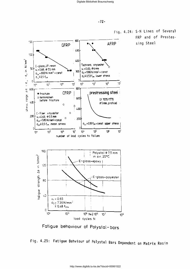
N
E E -... z ~
t:l~
0
~so.---------~
GFRP
iOO
so
-72-
24 S-N Lines of Several Fig. 4. : FRP and of Prestes-
~~---------sing Steel ."\
··~ .. AFRP
T echnoro, vinyl ester~ v1 =0,65; ~ 6 mm Oct =1000N/mmZ = const. 0c1=o.53fC111 lower stress
OL----L..:--7--:: o; Lo-· --....l.,o-,---, .. o:.-6 --,a' 104 10j 106 10'
0 600 ~-------------, ooo~--------------~
<l • tracture CFRP <11 0"1
prestressing steel I
c:: Cl st 15101mo ' 600 '- 400
o tenmnatlon before fracture
~ 5 mm, profiled Ill Ill <lJ
.!::: Ill
0 9 400
c- fi t:ler, vtnylester 0 I
0 200 v1 =0,63; ~ 0,5 mm o,m=580 N/nrnl=ccnst a~= O, 5 f cm mean stress
200
10~
z ~ t:l <l
L
160
number of load cycles to failure
1 Polystol 1/> 7.5 mm 1
1 tn otr, 20°C
E -gloss•epoxy I 1~~--------~~---,~-----r------~
0, c 80~----~-~~~~~-----r------~ (l) '-
Vi (l) :J 0'1 o L.O
Vt: 0.65 a0 = 736N/mm=
; 0.48 fctl<
0~------~------_. __ ._ ____ ~-------104 10 5 106 N: 2 106 10 7 10B
load cycles N
Fatigue behaviour of Polystal- bars
Fig. 4.25: Fatigue Behviour of Polystal Bars Dependent on Matrix Resin
Digitale Bibliothek Braunschweig
http://www.digibib.tu-bs.de/?docid=00061522
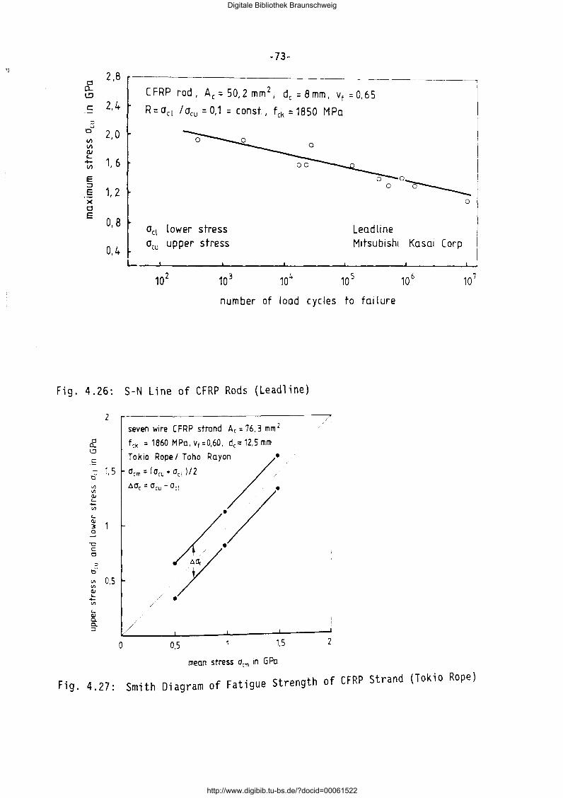
13
6: 2,8
I!)
c 2.4 ·-
:::J u
0 V)
2,0 V)
ClJ '-~ V) 1, 6
E :J E 1, 2 X 0 E
0, B
0,4
Fig. 4.26:
2
& l.:l
~ - 1.5 t)
Vl Vl (lj '--Vl
'-(lj
3 0
"'0 c: t:l
::> ou
Vl 0,5 Vl (lj '--Vl
'-(lj Cl. c. :J
0
-73-
CFRP rod, Ac=50,2mm2i d, =Bmm, vf =0,65
R=act lacu = 0,1 = const, fck = 1850 MPa
00~
act lower stress acu upper stress
Lead line Mitsubishi Kasai Carp
0
L--~----~------~----~------L-----~ 10
2
number of I oad c ye les to failure
S-N Line of CFRP Rods (Leadline)
seven wtre C FRP strand Ac = 76, 3 mm 2
fck = 1860 MPa,Vt=0,60, dc:::12,5mm
Tok~ Rope/ Toho Rayo~• Ocm-(Ocu•Octl/2 ./
•a, " a, - '" ·/'
/ . /
/
0,5 1,5 2
mean stress acm tn G Po
Fig. 4.27: Smith Diagram of Fatigue Strength of CFRP Strand (Tokio Rope)
Digitale Bibliothek Braunschweig
http://www.digibib.tu-bs.de/?docid=00061522
-74-
ted in a Smith diagram. For an upper stress of acu z 1150 MPa z 0,62 fck a
stress range of t:.ac = 310 MPa was endured for 2·106 load cycles. Prestres
sing steel strand St 1570/1770 exhibits under such condition a fatigue
stress range of about t.ap z 200 MPa. It is interesting to note that the
stress range is almost independent on the mean stress am.
4.5 Literature
[ 4. 1] :
[ 4. 2]:
[ 4. 3] :
[4.4]:
[ 4. 5] :
(4.6]:
[ 4. 7]:
[ 4. 8]:
Chawla, K.K.: Composite Materials. Science and Engineering. Sprin
ger-Verlag, New York, 1987.
Ruegg, Ch.: Koh 1 enfaser- und Aramidfaserkunststoffe fur Kardan
wellen. Verarbeiten und Anwenden kohlenfaserverstarkter Kunst
stoffe. VOI-Verlag, Dusseldorf, 1981.
Niederstadt, G.: EinfluB der Betriebsbedingungen auf das Festig
kei tsverha lten van CFK. Lei chtbau mi t kohl enstoffaserverstarkten
Kunststoffen. Band 167, Kontakt & Studi urn Werkstoffe, Expert Verlag, Sindelfingen, 1985.
Rehm, G.; Franke, L.: Kunstharzgebundene Glasfaserstabe als Beweh
rung im Betonbau. Deutscher AusschuB fur Stahlbeton, Heft 304, 1979.
He 1 mer, T. ; Wanner, A.; Kromp, K.: Prufmethoden fur fa server
s tarkte Kerami ken. Prufen neuer Werkstoffe, Prufmethoden - Anwen
dung und Aussagefahigkeit. DVM-Tag 1990, Bauteil '90, S. 297 -312.
Rehm, G.; Schlottke, B.: Obertragbarkeit van Werkstoffkennwerten
bei Glasfaser-Harz-Verbundstaben. Mitt. des Inst. fur Werkstoffe, Universitat Stuttgart 1987/3.
Franke, L.: Schadensakkumulation und Restfestigkeit im L icht der
Bruchmechanik. Festschrift G. Rehm, Verlag w. Ernst u. Sohn, Ber-1 in.
Franke, L.; Wolff, R.: Fibre Glass Tendons for Prestressed Con
crete Bridges. IABSE-Congress, Helsinki, June 1988, pp. 51/56.
Digitale Bibliothek Braunschweig
http://www.digibib.tu-bs.de/?docid=00061522
-75-
(4.9]: den Uijl, J.A.: Mechanical Properties of Arapree. Part 4: Creep
and Stress-rupture. Report 25-87-31, TU Delft, 1991.
(4.10]: Dengel, D.: Empfehlungen fur die statische Abschatzung des Zeit-
und Dauerfestigkeitsverhaltens von Stahl. M t · u k a .-WlSS. U. wer -stofftech. 20 (1989), pp. 73/81.
[4.11]: Niederstadt, G.: Kriterien und Beispiele fur die Wahl von Ver
bundwerkstoffen m it Fasern hoher spezi fi se her Eigenschaften.
Kunststofftechnik, Kohlenstoff- und aramidfaserverstarkte Kunst
stoffe. VDI-Verlag, Dusseldorf, 1977.
[4.12] Chiao, T.T.; Wells, J.E.; Moore, R.L.; Hamstad, M.A.: Stress-Rup
ture Behavior of Strands of an Organic Fiber/Epoxy Matrix. 3rd
Conf. on Composite Materials: Testing and Design, ASTM STP 546,
1974, pp. 209/224.
[4.13] Gerritse, A.; Maatjes, E.; Schurhoff, H.J.: Prestressed Concrete
Structures with High-Strength Fibres. IABSE Report Vol. 55, ZU
rich, 1987, pp. 425/432.
[4.14] Gerritse, A.; Schurhoff, H.J.; Maatjes, E.: Prestressed Concrete
Structures with Arapree; Relaxation. IABSE -Symp.: Concrete Struc
tures for the Future, Versailles, 1987.
[4.15] Waaser, E.; Wolff, R.: Ein neuer Werkstoff fur Spannbeton. HLV
Hochleistungs-Verbundstab aus Glasfasern. beton 36, 1986, H.7, PP·
245/250.
[4.16] Leadline Product Information on Carbon Fiber Tendons/Bars by Mit
subishi Kasai Corp., 1991.
[4.17]
[4.18]
Zoch, P.; Kimura, H.; Iwasaki, T.; Heym, M.: Zugelemente aus koh
l enstofffaserarmi ertem Kunststoff, ei ne neue Kl as se von VorspannfUr werkstoff im
materialien. Forschungskolloquium am Institut
Bauwesen, Universitat Stuttgart, Nov. 1991.
Franke' L. ; Overbeck' E. : Oauerschwi ngverha lten von Gl as faserver
bundstaben im anwendungsori ent i erten Zugschwe 11 be rei eh· Bautechn i k
66, 1989, H. 3, pp. 90/92.
Digitale Bibliothek Braunschweig
http://www.digibib.tu-bs.de/?docid=00061522
[4.19]
[4.20]
[4.21]
-76-
Kakihara, R.; Kamiyoshi, M.; Kumagi, S.; Noritake, K.: A New Ara
mid Rod for the Reinforcement of Prestressed Concrete Structures.
ASCE Spec. Conf.: Advanced Composites Materials in Civil Enginee
ring Structures, Las Vegas, 1991, pp. 132/142.
Walton, J.M.; Yeung, Y.T.C.: The Fatigue Performance of Structural
Strands of Pultruded Composite Rods. Journal of the Institute of
Mechanical Engineers, London, C 286/86, 1986, pp. 315/320.
Nurnberger, U.: Dauerschwingverhalten von Spannstahlen. Bauingeni
eur 56, 1981, pp. 311/319.
Digitale Bibliothek Braunschweig
http://www.digibib.tu-bs.de/?docid=00061522
-77-
5. CORROSION RESISTANCE OF FRP
5.1 Practical Relevance
One of the main reasons of the search for alternatives for reinforcing and
prestressing steel is the danger of corrosion for normal carbon steel under
conditions like low alkalinity of the concrete due to carbonization and
eh 1 ori de contamination of the concrete cover. But it is a 1 so we 11 known,
that the durability of some polymers and fibers, especially in alkaline en
vironments is insufficient.
If FRP are to overcome the corrosion suscept i bi 1 i ty of stee 1 in aggressive
environments they have to ensure, that they can withstand sufficiently such
conditions during the service life of the concrete member.
5.2 Relevant Environments
The basic environment for the reinforcing and prestressing with FRP or steel
e 1 ements is the concrete i tse 1 f. For FRP e 1 ements is - wh i eh respect to
eventual corrosion - the composition of the pore water solution of the con
crete essential. The composition depends on the type of the cement and va
ries especially in the amount of alkalies. Usually the pore solution con
sists of a saturated Ca(OH) 2 solution with 4 - 10 g/1 Na+ and K+ (expressed
as Na+-equivalent) ions.
The pH-value of an uncarbonated concrete is about 13. Due to carbonization
the content of Ca(OH)2
and of free Na+ and K+ decreases considerably. Since
the carbonization process cannot be predicted accurately, the relevant envi
ronment for the investigation of the corrosion of FRP elements should be
either an uncarbonated concrete or an equivalent solution, because this en
vironment causes the strongest chemical attack to FRP.
When examining the durability of FRPs it is difficult to embed the specimens
in concrete and to subsequent 1 y recover them from the concrete for testing
Without damage. Therefore artifical solutions should be used. For these so
lutions it is very important to use not only a saturated Ca(OH)2 solution,
but also a solution containing alkali ions. Because of the different ion
diameter and the different electrical loading, the diffusion velocity of
ea++ is lower than that of Na+ and K+. As the chemicals have to diffuse
Digitale Bibliothek Braunschweig
http://www.digibib.tu-bs.de/?docid=00061522
-78-
through the matrix resin before they can attack the fibers, their diffusion
velocity through the resin is of great importance. For this reason a test
solution consisting of saturated Ca(OH) 2 + 0,4 n KOH is recommended.
Chloride in concrete do not attack any of the FRP elements treated here.
Therefore chloride containing solutions do not have any value in the tests.
Other chemicals like acids and solvents could be important for the durabi-
1 ity of the tensile elements if they come into contact with them. Because
concrete is a porous material this could happen, e.g. in case of storage fa
cilities. Therefore the chemical resistance of FRP should be tested with all
chemicals relevant to a specific application.
5.3 Types and Mechanisms of Corrosion
5.3.1 Corrosion of Aramid Fibers
Strength and stiffness of aramid fibers depend on the chemical structure of
the polymer. The polymer is built up out of hundreds of long and stiff molecular chains, which are interconnected by hydrogen bonds. A part of these chains is shown in Fig. 2.2.
Aramids are affected by two different chemical processes. One process is the degradation of hydrogen bridges. If water molecules diffuse into the poly
mer, the hydrogen bonds are re so 1 ved and the bond between the chains is re
duced. As result of this the strength decreases. But this process is reversible if the FRP element is dried.
A real corrosion process occurs in the presence of alkaline solutions. KOH
solutions for instance hydrolize the linkages between the c and the N atoms and the long chains are cut.
Since the strength of the aramid fibers depends on the length of the molecu
les, a decrease of the length of the molecular chain results in a lower strength. This process is irreversible.
5.3.2 Corrosion of Carbon Fibers
Because of their chemical structure carbon fibers are inert against nearlY
all chemicals. They do not corrode in any of the environments concrete structures will normally be subjected to.
Digitale Bibliothek Braunschweig
http://www.digibib.tu-bs.de/?docid=00061522
-79-
5.3.3 Corrosion of Glass Fibers
The corrosion process of glass fibers in strong alkaline solutions has not
yet been precisely examined. Probably the complex silicate ions dissolve as
a function of the pH value. Thereby the silicate network is decomposed,
while in case of an acid environment only single ions are exchanged against H+ ions.
The reaction products of the alkali ne corrosion process form a lay er upon
the fiber surface which becomes thicker and thicker. This layer is normally
not tight against alkali ions, so that the degradation process continues
with time. It was found out, that the alkaline corrosion resistance of dif
ferent kinds of glass fibers mainly depends on the content of multivalent
metal oxides. These metal oxides form a layer on the fiber surface. If unso
luable Ca compounds are available, these compounds are integrated in the
surface layer and condenses it to an extent, that it becomes tight against
a l ka l i ions .
The alkali resistance of glass fibers can be enhanced by the addition of
Zro2 and Ti02.
5.3.4 Rate of Corrosion
The velocity of corrosion is dominated by two processes. The first process
is the diffusion, which is determined by the time t, the absolute tempera
ture T, the gradient of concentration c, the length of the diffusion path x,
diffusion coefficient D and the cross-sectional area of diffusion q. The
equation for this process is:
llm
lit
de D
dx
with the diffusion coefficient
D = D exp [- ~] 0 RT
( 5 . 1 )
(5.2)
Digitale Bibliothek Braunschweig
http://www.digibib.tu-bs.de/?docid=00061522
-80-
wherein
m mass flux of diffused material
activation energy universal gas constant basic diffusion coefficient
If corroding substances have reached the fibers, the velocity of the chemi
cal degredation process v is determining the residual strength r.
f(v) = r (5.3)
Chemical reactions like hydrolysis of the C-N link in case of the aramids or the dissolution of complex silicate ions in case of glass follow the Arrhe-
nius equation:
d(l-r)
dt K exp [- ~Tl
(5.4)
(5.5)
with K as a constant, which can be determined by variation of the tempera
ture of the test. Thereby it is possible to accelerate the corrosion by elevated temperature and to be able to predict the long-term behaviour by means of tests taking only some months.
5.4 Corrosive Effects on Strength
One has to distinguish between the temporary and permanent reduction of strength. In the case of aramid fiber composites water saturation leads to a temporary reduction of strength of 5 to 10 % and a reduction of tens i 1 e Young's modulus of 5% because of the degradation of H-bridges. This loss of strength is nearly fully reversible when the composite is dried.
In an alkaline solution, as described in sec. 5.2, the residual strength of an aramid/epoxy composite is 95 % of the initial strength at a temperature of 20 •c after lOO years.
Digitale Bibliothek Braunschweig
http://www.digibib.tu-bs.de/?docid=00061522

-81-
Generally valid data for the development of residual strength of glass fiber composites cannot be presented, because the influence of type of glass and type of resin is very important. Comparable tests between aramid/epoxy composites and E-glass/epoxy composites show a higher loss of strength in alkaline solutions for the glass fiber composites.
5.5 Protective Measures
The most important protective measure to increase the corrosion resistance of AFRP and GFRP is the choice of the matrix resin. Resins with a high dif
fusion resistance should be preferred.
An outer layer of resin without fibers prolongs the time of diffusion.
Measures like coating with thermoplastics are not very effective, because
their diffusion resistance against water and alkalies is low.
If the long-term corrosion resistance of a composite is too low, the alkalinity of the concrete can be reduced. One poss i bi 1 i ty is the choice of cements and concretes with a lower alkalinity. In case of post-tensioning with bonded tendons the use of resin mortars for the injection of the ducts may
also be solution.
Digitale Bibliothek Braunschweig
http://www.digibib.tu-bs.de/?docid=00061522
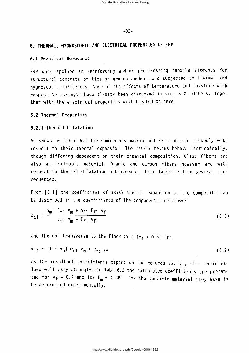
-82-
6. THERMAL, HYGROSCOPIC AND ELECTRICAL PROPERTIES OF FRP
6.1 Practical Relevance
FRP when applied as reinforcing and/or prestressing tensile elements for
structural concrete or ties or ground anchors are subjected to thermal and
hygroscopic influences. Some of the effects of temperature and moisture with
respect to strength have already been discussed in sec. 4. 2. Others, toge
ther with the electrical properties will treated be here.
6.2 Thermal Properties
6.2.1 Thermal Dilatation
As shown by Table 6.1 the components matrix and resin differ markedly with
respect to their thermal expansion. The matrix resins behave isotropically,
though differing dependent on their chemical composition. Glass fibers are
also an isotropic material. Aramid and carbon fibers however are with
respect to thermal dilatation orthotropic. These facts lead to several con
sequences.
From [6.1] the coefficient of axial thermal expansion of the composite can
be described if the coefficients of the components are known:
aml Eml vm + afl Efl vf
Eml vm + En vf
and the one transverse to the fiber axis (vf > 0,3) is:
( 6. 1)
(6.2)
As the resultant coefficients depend on the columes vf, vm, etc. their va
lues will vary strongly. In Tab. 6.2 the calculated coefficients are presen
ted for v f = 0. 7 and for Em = 4 GP a. For the specific materia 1 they have to be determined experimentally.
Digitale Bibliothek Braunschweig
http://www.digibib.tu-bs.de/?docid=00061522
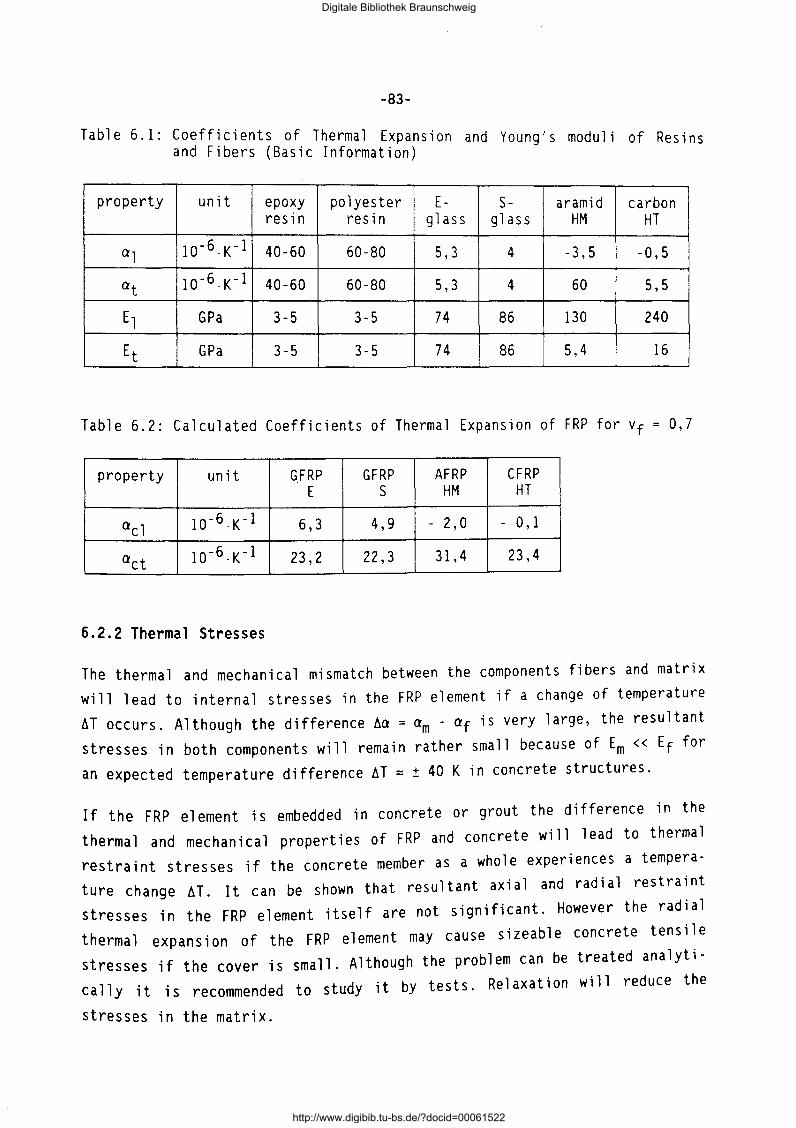
-83-
T a b l e 6 . 1 : C o e f f i c i en t s o f T h e rm a 1 Ex pan s ,· 0 n d y ' d 1 an oung s mo u i of Resins and Fibers (Basic Information)
property unit epoxy polyester E- S- a ram id carbon resin resin glass glass HM HT
al l0-6.K-1 40-60 60-80 5,3 4 -3,5 -0,5
at l0-6.K-1 40-60 60-80 5,3 4 60 5,5
El GP a 3-5 3-5 74 86 130 240
Et GP a 3-5 3-5 74 86 5,4 16
Table 6.2: Calculated Coefficients of Thermal Expansion of FRP for vf 0,7
property unit G.FRP GFRP AFRP CFRP E s HM HT
acl 10 -6.K-1 6,3 4,9 - 2,0 - 0' 1
act 1o-6.K-1 23,2 22,3 31,4 23,4
6.2.2 Thermal Stresses
The thermal and mechanical mismatch between the components fibers and matrix will lead to internal stresses in the FRP element if a change of temperature AT occurs. Although the difference Aa =am - af is very large, the resultant stresses in both components will remain rather small because of Em<< Ef for an expected temperature difference AT = ± 40 K in concrete structures.
If the FRP element is embedded in concrete or grout the difference in the thermal and mechanical properties of FRP and concrete will lead to thermal restraint stresses if the concrete member as a whole experiences a temperature change AT. It can be shown that resultant axial and radial restraint stresses in the FRP element itself are not significant. However the radial thermal expansion of the FRP element may cause sizeable concrete tensile stresses if the cover is small. Although the problem can be treated analytically it is recommended to study it by tests. Relaxation will reduce the
stresses in the matrix.
Digitale Bibliothek Braunschweig
http://www.digibib.tu-bs.de/?docid=00061522
-84-
6.2.3 Combustability
FRP are combustible materials due to the polymeric resin. Thus, for such purposes where an adequate fire resistance of the structural element is requi red, protective measures are necessary (sufficient concrete cover, ther
mally insulating cover, etc.).
6.3 Hygroscopic Properties
6.3.1 Water Absorption
A fiber composite will absorb water when stored for a long time in moist environment (e.g. also in fresh and hardened concrete, etc.). This leads to an increase of weight per unit volume and to swelling. Both water absorption and swelling are reversible processes, vanishing upon drying.
The fibers behave differently with respect to water absorption. While glass and carbon fi bers do not absorb water, a rami d fi bers wi 11 . A rami d fi bers will attain, when stored in a climate of 20 oC/65% r.h., an equilibrium moisture content of about 3 - 4 m.-%, or when stored under water about 8 m.% (mass percent). Because absorption and desorption of FRP is mostly connected with the change of ambient temperature, it is often denoted as hydrothermal behaviour.
The greater portion of the water, absorbed in FRP, is stored within the macromolecular structure of the matrix resin. As the water molecules force the polymer chains apart, swelling of the FRP transverse to the fiber axis occurs. This leads to several consequences. The glass transition temperature and the strength of the FRP are 1 owe red with increasing moisture content (max Amc ~ 4 to 8 %). Hygroscopic stresses arise.
6.3.2 Swelling and Hygroscopic Stresses
As for the thermal expansion, the swelling of FRP depends also on the volume fractions and mechanical properties of the components. Swelling is only significant in the direction transverse of the fiber axis. The transverse coefficient of swelling can be expressed for a CFRP in epoxy matrix with vf ~ 0,58 at 20 oc dependent on the absorbed mass of water [6.2]:
acts z 5 · lo- 3;m.-%,
Digitale Bibliothek Braunschweig
http://www.digibib.tu-bs.de/?docid=00061522
-85-
and the swelling strain is then
with hm the mass gain in m.-% due to water absorption. Swelling in axial direction is practically nil.
Swelling will also entail internal hygroscopic stresses comparable with
thermal stresses. They will be significally reduced by stress relaxation. The tightness of the matrix resin against ingress of water is an important property.
As mentioned the uptake of water reduces the tensile strength slightly. Upon
drying the loss of strength is regained, s. sec. 4.2.5.
6.4 Electrical and Magnetic Properties
FRP cannot conduct electrical currents nor can they be electrically magnetized. This virtue may be of advantage for several practical applications,
e.g. for antenna stays.
6.5 Literature
[ 6. 1]
[6.2]
Chawla, K.K.: Composite Materials Science and Engineering. Sprin
ger-Verlag, New York, 1987.
NiedersUi.dt, G.: Verbund- und Hybridwerkstoffe. Neue Methoden fur
Konstruktion und Fertigung. VDI BW 43-10-04, April 1990.
Digitale Bibliothek Braunschweig
http://www.digibib.tu-bs.de/?docid=00061522
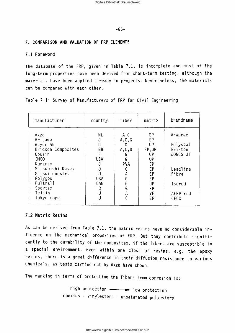
-86-
7. COMPARISON AND VALUATION OF FRP ELEMENTS
7.1 Foreword
The database of the FRP, given in Table 7.1, is incomplete and most of the long-term properties have been derived from short-term testing, although the materials have been applied already in projects. Nevertheless, the materials can be compared with each other.
Table 7.1: Survey of Manufacturers of FRP for Civil Engineering
manufacturer country fiber matrix brandname
Akzo NL A,C EP Arapree Arisawa J A,C,G EP Bayer AG D G UP Polystal Bridson Composites GB A,C,G EP,UP Bri-ten Cousin F G UP JONCS JT IMCO USA G UP Kuraray J PVA EP Mitsubishi Kasei J c EP Leadline Mitsui constr. J A EP Fibra Polygon USA G EP Pultrall CAN G UP Isorod Sport ex D G EP Teijin J A VE AFRP rod Tokyo rope J c EP CFCC
7.2 Matrix Resins
As can be derived from Table 7.1, the matrix resins have no considerable influence on the mechanical properties of FRP. But they contribute significantly to the durability of the composites, if the fibers are susceptible to a special environment. Even within one class of resins, e.g. the epoxy resins, there is a great difference in their diffusion resistance to various chemicals, as tests carried out by Akzo have shown.
The ranking in terms of protecting the fibers from corrosion is:
high protection -----~~•~ 1 ow protection epoxies - vinylesters - unsaturated polyesters
Digitale Bibliothek Braunschweig
http://www.digibib.tu-bs.de/?docid=00061522
-87-
Concerning the processing of the resins, the viscosity is of major importance. A low viscosity enables a high production speed, which reduces the cost price of the FRP. The order of costs including the raw material costs of the resins is:
high production costs low production costs epoxies - vinylesters - unsaturated polyesters
7.3 Mechanical Properties
The mechanical properties of the FRP are mainly determined by the fibers and the applied production technology.
The tensile strength related to the same fiber cross-section is slightly influenced by the type of fiber, except the PVA composite, which has a much lower strength. For the most part it is in the range between 2400 MP a and 3000 MPa.
But there is a distinct influence of the production technology with respect to arrangement of the fibers in the composite on the strength. Although the tensile strengths of the pure fibers from Arapree and Fibra are nearly the same, there is a reduction in strength of more than 20% for the Fibra com
posite due to the braiding of the fibers.
A similar loss of tensile strength occurs to CFCC strand. The reduction of the strength from the fi ber to the FRP element with the 1 argest number of individual wires amounts to 38 %. This considerable reduction of strength has mainly two causes. One is the use of fiber prepregs. Pictures of crosssection show a variation of the fiber orientation and some air bubbles in
the composite.
The second reason for the reduction of the tensile strength is the stranding of several wires of FRP to a strand. As a result of this the fiber direction deviates from the strand axis. Since carbon (and also aramid) fibers are highly orientated fibers with a very high tensile strength in the fiber axis and a low strength transverse to the fiber axis, the tensile strength of the
FRP strand decreases.
Digitale Bibliothek Braunschweig
http://www.digibib.tu-bs.de/?docid=00061522

-88-
The ultimate elongation of FRP is between 1,3% and 3,8 %. Carbon fiber composites have a maximum elongation of 1,6 %, the aramid FRP range between 2,0% and 3,7% and the glass fiber composites range between 3,0% and
3,8 %.
The tensile moduli are contrary to the ultimate elongation. Glass-FRP have the lowest modulus of about 70000 MPa (related to the effective fiber crosssection), aramid-FRP range between 70000 MPa and 140000 MPa, whereas carbonFRP have moduli between 235000 MPa and 400000 MPa.
The relaxation loss of glass and carbon fiber composites is in the order of 3%- 5% after 100 years, whereas aramid FRP have a relaxation of 15%-30 %.
Stress-rupture data are only available of Arapree and Polystal. The general behaviour of carbon FRP can be deduced from tests of other applications than civil engineering. The ranking according to these tests is:
high stress-rupture strength .. low stress-rupture strength carbon FRP - aramid FRP - S-glass FRP
Fatigue tests have been carried out with aramid, carbon and glass FRP. These tests have shown, that aramid and carbon composites have a similar fatigue resistance, which is higher than that of prestressing steel, whereas the fatigue of glass FRP is considerably lower.
The relevant parameters to characterize the shear force capability are interlaminar shear strength and bond strength. Only a few data are available, which are in the same order of magnitude. The bond strength in concrete of the composites with a special surface treatment ranges between 7, 2 MP a and 8,2 MPa, the ILLS between 35 MPa and 45 MPa.
7.4 Physical Properties
An important physical property is the coefficient of thermal expansion. The vallues parallel to the fiber axis are mainly determined by the fiber behaviour. In case of ararnid FRP it is between -1,8xlo-6;K and -5,2xlo-6;K, in case of carbon FRP it is about 0,7xlo-6;K and for glass FRP 7,0xlo-6;K.
Digitale Bibliothek Braunschweig
http://www.digibib.tu-bs.de/?docid=00061522
-89-
Of similar importance is the coefficient of thermal elongation transverse to the fiber axis, as damages in demonstration projects have shown. For Arapree a value of 50xlo- 6;K has been measured. The coefficients of thermal elongation of the other composites have not been measured yet, but calculations on the basis of the fiber and the matrix resin behaviour (which is substantial), come to values between 30xlo-6;K and 50xlo-6;K.
Digitale Bibliothek Braunschweig
http://www.digibib.tu-bs.de/?docid=00061522
-90-
8. EVALUATION OF THE POTENTIALS AND SHORTCOMINGS OF FRP ELEMENTS AND THEIR PRODUCTION TECHNOLOGIES ON THE BASIS OF THE REQUIREMENTS OF TASK 1.1
8.1 Foreword
The requirements of the FRP as prestressed tensile elements are described in Task 1.1 separately for pre- and posttensioning. For the most part the same requirements are valid for pretensioning and posttensioning with and without bond. Therefore the following appraisal is split up only when the requi
rements are varying.
8.2 Mechanical Properties
8.2.1 Linear tensile strength
The short-term tensile strength of all FRP except the Kuraray PVA composite is higher than those of prestressing steel. In contrast to steel they show a noticeable reduction in the long-term strength. But the utilizable strength and the design strength are similar to that of prestressing steel and therefore generally sufficient. A reduction of strength due to corrosive environments is possible. This item will be dealt with in sec. 8.4.
8.2.2 Transverse compressive strength
Since steel is an isotropic material, its properties are the same in all directions. Therefore transverse loading of steel at saddles of anchorages is no problem, unless high pressures occur.
Because all FRP have a low transverse compressive strength and no plastic deformation capacity, attention has to be paid to multiaxial loading. Especially anchoring of FRP in posttensioning without bond is a problem. Solutions exist in some cases (e.g. by SICOM).
8.2.3 Young's modulus and failure strain
The 1 ower modulus of a rami d and glass FRP against stee 1 has the advantage, that the loss of prestress due to the shrinkage and creep of the concrete is lower. The greater elongation at stressing due to the lower modulus does not really matter.
Digitale Bibliothek Braunschweig
http://www.digibib.tu-bs.de/?docid=00061522

-91-
Concerning the ultimate limit states it should be kept in mind, that FRP are nearly totally elastic materials up to fracture without any plastic deformations. It has to be examined, whether the deformation capacity of FRP and especially of carbon fiber· composites is sufficient and which strain limitations are required.
8.2.4 Bond strength
The FRP surface can easily be adjusted to distinct bond requirements in case of the prepreg technology. The classic pultrusion technology does not offer this possibility, but online adjustments are possible with modified processes.
8.2.5 Relaxation losses
Restrictions due to the relaxation are not required. The higher relaxation of aramid fiber composites is only of economic importance and does not limit its fields of application.
8.2.6 Fatigue strength
The fatigue strength of aramid and carbon FRP is twice as high than that of prestressing steel. Benefit can be taken from this property in dynamic
loaded structures like railway sleepers.
Glass fiber composites have only 1/4 of the fatigue strength of steel, which limits its applications and efficiency in dynamic loaded structures.
8.3 Physical Properties
8.3.1 Poisson ratio
In terms of prestressing with direct bond the higher splitting forces in the
anchorage zone due to the higher Poisson ratio are a real problem.
The problem has to be overcome by additional reinforcement or by other
measures like compressible coatings on the FRP.
Digitale Bibliothek Braunschweig
http://www.digibib.tu-bs.de/?docid=00061522
-92-
8.3.2 Coefficient of thermal expansion
One reason for the success of steel reinforced concrete is the same coefficient of thermal expansion of steel and concrete.
FRP have a different coefficient of thermal expansion, which leads in longitudinal direction to a slight change of the concrete prestress.
In case of prestressing with direct bond there may exist a problem due to the higher transverse coefficient of thermal elongation of the FRP. Additional splitting forces emerge which can crack the concrete. Therefore special measures have to be taken like additional reinforcement or compressible coatings of the FRP.
At posttensioning there is no problem regarding the transverse coefficient of thermal elongation, because the ducts can carry the additional splitting forces.
8.3.3 Thermal resistance
Aramid, carbon and glass fibers have a good thermal stability and high residual strengths at elevated temperatures, whereas the thermal stability of PVA fibers is bad.
The 1 imiting factor in case of aramid, carbon and glass FRP is the matrix resin, because it has the lowest thermal stability and is responsible for the force transfer from the composite to the concrete. Depending on the kind of resin, the mechanical properties decrease between 89 oc and 200 oc, which is much lower than for steel.
To achieve a sufficient fire resistance period special attention should be paid to the anchorage zone.
8.4 Chemical Properties
The resistance against corrosion is the most important item, because this property is the biggest shortcoming of steel.
The carbon FRP show the best corrosion resistance, since carbon fibers are absolutely inert.
Digitale Bibliothek Braunschweig
http://www.digibib.tu-bs.de/?docid=00061522
-93-
The corrosion resistance of aramid FRP has been tested in all relevant environments. The most corrosive environment is an alkaline medium. The findings in a solution of saturated Ca(OH) 2 + 0,4 n KOH result in a residual strength of 85 % after lOO years.
Durability tests of glass fiber composites show varying results. Polystal for example has a sufficient resistance, whereas tests in the U.S.A. with polygon composites (S 2 glass in a matrix of epoxy resin) gave discouraging results. Concrete beams prestressed with polygon FRP and immersed in the seawater splashzone for 9 months had a reduction in strength of 72%. Further testing of glass FRP is required to get sufficient certainty.
8.5 Handling
FRP are about 5 times 1 ighter and more flexible than steel, which makes handling much easier.
Spec i a 1 cautions during storage are not necessary contrary to prestress i ng steel. FRP should only be protected from impact loading from heavy tools or
from surface injury.
8.6 Design Requirements
FRP can be applied according to the standards valid for prestressed concrete
with some modifications.
An advantage can be taken from the crack width limitation, which is required to protect steel from corrosion. Since the FRP are not susceptible to corrosion, this requirement is irrelevant. Other desing requirements are already
mentioned in Task 1.1.
Digitale Bibliothek Braunschweig
http://www.digibib.tu-bs.de/?docid=00061522

-94-
9. SUGGESTIONS FOR MODIFICATIONS OF FRP ELEMENTS AND THEIR PRODUCTION TECH
NOLOGIES
9.1 FRP Elements
Modifications of FRP are necessary with respect to their bond behaviour. Different coatings and surface structures should be developed.
A severe problem in prestressing with direct bond is the transverse coefficient of thermal elongation, which is about 5 times higher than that of concrete. Research in this field is necessary to overcome this problem. Possi
ble solutions may be compressible coatings.
If the durability of composites is insufficient, the choice of matrix resins with a higher diffusion resistance might be a solution. Additional coatings can also work in the same way.
9.2 Production Technologies
The most important subject to get a FRP with good mechanical properties is the fiber orientation. Deviations of the fiber axis from the composite axis lead to significant reductions. This happens if the fibers are braided or if the fibers are twisted to strands.
The same attention has to be put to the fiber tension during production. At normal pultrusion the fibers are taken from the bobbin without care to equal tension in the fibers. Embedded in the matrix resin some fibers are slightly stressed and other fibers are not stressed. If these composites are prestressed during the application, the fibers get a different level of loading. The results are a lower tensile strength and a lower ultimate elongation.
The embedding of air bubbles in the FRP leads to a reduction of the diffusion resistance of corrosive media and therefore to a worse durability.
The parallel allignment of the fibers is also affected.
Sufficient curing of the composites is necessary to reach a high glass transition temperature of the resin, which equals a good thermal stability. Furthermore a well-cured resin has a higher degree of crosslinking and there-
Digitale Bibliothek Braunschweig
http://www.digibib.tu-bs.de/?docid=00061522
-95-
fore a better diffusion resistance. If online curing is not sufficient, an
additional offline curing is required.
Digitale Bibliothek Braunschweig
http://www.digibib.tu-bs.de/?docid=00061522