Embed Size (px)
Citation preview
ECE 4606 Undergraduate Optics Lab
Robert R. McLeod, University of Colorado
Fiber optic communicationOutline
140
•Lecture 12–Fiber optic communication
• Introduction
• Properties of single- and multi-mode fiber
• Optical fiber manufacture
• Optical network concepts
Pedrotti3, Chapter 10

ECE 4606 Undergraduate Optics Lab
Robert R. McLeod, University of Colorado 141
P(t) Direct modulationPower, λ stability
Chirp
Optical communication
simple block diagramV(t)
V(t)
Original signalE.g. analog voice
Many channels muxed
into larger total BW
Digital encodingModulation, error
correction, routing and
header info
P(t) TransmissionAttenuation, jitter,
noise, polarization
scrambling, dispersion
λ MultiplexingCrosstalk, loss
i(t)
DemultiplexingCrosstalk, loss
DetectionNoise, bandwidth
V(t)
DecodingBit error rate
•Lecture 12–Intro

ECE 4606 Undergraduate Optics Lab
Robert R. McLeod, University of Colorado 142
Time-division multiplexingBundling low bandwidths
•Electronic aggregation of multiple low-bandwidth
streams.
•Eventually exceed available modulation rate of
electronics and optics.
•Standard today is 10 Gb/s with 40 Gb/s being fielded.
• Optical carrier (at λ = 1.5 µm) is 200 THz, so there is
room for a number of these TDM channels
• Available bandwidth is determined by fiber
•Lecture 12–Intro

ECE 4606 Undergraduate Optics Lab
Robert R. McLeod, University of Colorado 143
Wavelength division multiplexingto exploit transmission bandwidth
• Also known as frequency multiplexing
• Mux/demuxers need flat passbands in both amplitude and phase to not
distort the data, then very sharp filter edges to suppress crosstalk
between channels.
• Gratings are an obvious technology but are difficult to package with
sufficient stability.
• Daisy chains of thin film band-drop filters can be used
• Array waveguide gratings – essentially an integrated optic grating –
are becoming the dominant technology
http://en.wikipedia.org/wiki/Image:Arrayed-Waveguide-Grating.svg
•Lecture 12–Intro

ECE 4606 Undergraduate Optics Lab
Robert R. McLeod, University of Colorado 144
Fiber optics primerCapture via total internal reflection
•For a perfectly flat surface, TIR is a 100% efficient mirror
•Once captured inside a higher index region, light will never exit
•Bending the guide decreases the incidence angle resulting in optical loss
•Lecture 12–Fiber properties
ECE 4606 Undergraduate Optics Lab
Robert R. McLeod, University of Colorado 145
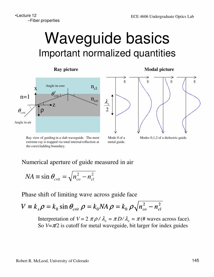
Waveguide basicsImportant normalized quantities
n=1
ncl
nco
critθ ′
critθ
z
x
ρ
Numerical aperture of guide measured in air
Phase shift of limiting wave across guide face
22
000 sin clcocritx nnkNAkkkV −===≡ ρρρθρ
Ray view of guiding in a slab waveguide. The most
extreme ray is trapped via total internal reflection at
the core/cladding boundary.
Interpretation of V = 2 π ρ / λx = π D/ λx = π (# waves across face).
So V=π/2 is cutoff for metal waveguide, bit larger for index guides
Angle in air
Angle in core
22sin clcocrit nnNA −=≡ θ
22
000 sin clcocritx nnkNAkkkV −===≡ ρρρθρ
Ray picture Modal picture
Mode 0 of a
metal guide.
Modes 0,1,2 of a dielectric guide.
E E E E
2
xλ
•Lecture 12–Fiber properties

ECE 4606 Undergraduate Optics Lab
Robert R. McLeod, University of Colorado 146
Single mode vs. multi-
mode fibers
Michelson, Chapter 5
m=1 m=10
ν=
0ν
=9
• Multi-mode guides have large V = large size = easy/cheap to align.
• BUT, each mode propagates at different speed, so pulse disperses.
• Only usable in short reach systems such as around buildings.
Electric field in transverse plane
•Lecture 12–Fiber properties

ECE 4606 Undergraduate Optics Lab
Robert R. McLeod, University of Colorado
Fiber modes and semiconductor
light sources
147
Single mode system
• Source = laser diode. Aperture size and NA related by diffraction limit.
• Fiber = single mode Mode diameter and NA related by diffraction limit.
• Can be nominally 100% efficient.
• Coupled must be precisely aligned on fiber axis. Tight tolerances (~micron or less)
• High brightness system.
Multi mode system
• Source = light-emitting diode. NA ~ 1 independent of aperture diameter
• Fiber = multi mode Finite NA, unrelated to core diameter
• Large losses in first lens due to LED radiation angle
• Any ray that hits core with sin(angle) < NA is coupled. Loose tolerances (~10 µm).
• Lower brightness system
Trace as single,
diffraction-limited
cone.
Trace as array of high
NA point sources.
Modal
coupling
scrambles
input
Single,
diffraction-
limited
output
SM Fiber
MM Fiber
LD
LED
Lost light
•Lecture 12–Fiber properties

ECE 4606 Undergraduate Optics Lab
Robert R. McLeod, University of Colorado 148
Power loss / distance in glassThe “transmission windows”
• This graph is the reason long-haul telecom uses 1.5 µm light
• At 0.15 dB/km, light goes 20 km before losing 3 dB.
• The two primary bands used (above) cover 1525 to 1610 nm and
give > 5 THz of available bandwidth.
Long Haul
telecom
Short haul
Datacom
~0.15 dB/km
C-band: 1525-1565 nm
L-band: 1570-1610 nm
> 5 THz of bandwidth
•Lecture 12–Fiber properties

ECE 4606 Undergraduate Optics Lab
Robert R. McLeod, University of Colorado 149
Pulse broadeningWaveguide and material dispersion
If fiber is single mode there will be no modal dispersion. Index contrast and core
diameter are reduced to support just one mode. Fractional index contrast is
typically 0.2-1% for MM fiber. Group velocity now depends on spectral width of
the pulse. This leads to the use of lasers (small intrinsic linewidth) over LEDs
(large intrinsic linewidth) for long-haul, single-mode communication.
λτ σσ LD=
To a good approximation in fiber, the GVD can be taken as the sum of material
and waveguide dispersion:
wgmat DDD += [ps / (km-nm)]
Index of refraction of silica and Ge:silica
Group index, vgroup ≡ c/ng
λλ
d
dnnng −=
Group velocity dispersion
12
2
2
10 λ
λ
d
nd
cD −= [ps / (km-nm)]
•Lecture 12–Fiber properties

ECE 4606 Undergraduate Optics Lab
Robert R. McLeod, University of Colorado 150
How fiber is madePreform fabrication
Chemical vapor deposition
Rotated for uniformity
~40 cm typical length
1630 oC
www.howstuffworks.com/fiber-optic5.htm
•Lecture 12–Fiber manufacture

ECE 4606 Undergraduate Optics Lab
Robert R. McLeod, University of Colorado 151
Fiber drawing
10
-20
m/s
ec
2000 oC
http://people.alfred.edu/~misture/demo/draw_tower.html
• Several km are drawn from a single preform
• Nonuniformities are reduced in scale at the same ratio, so the core
is atomically smooth.
•Lecture 12–Fiber manufacture

ECE 4606 Undergraduate Optics Lab
Robert R. McLeod, University of Colorado 152
Erbium doped amplifierAll-optical regeneration
Signal
in
Signal
out
• Pump laser at 980 nm or 1480 nm excites erbium doped fiber.
• Erbium fluoresces at 1550 nm, providing stimulated emission gain to the
communication signals. The doped fiber thus acts much like a laser but
without the end mirrors (single pass).
• Spontaneous emission of the erbium is a noise source, so the
amplification comes at the expense of reduced SNR.
http://en.wikipedia.org/wiki/Erbium-doped_fiber_amplifier
• After some 10’s of km, signal needs to be regenerated.
• Traditional technology (early 1990s) was to demux, detect,
electronically retime and restore, broadcast and mux. Expensive.
• Fiber amplifiers made it possible to regenerate in optical domain.
EDFA concept:
EDFA in reality:
•Lecture 12–Fiber network

ECE 4606 Undergraduate Optics Lab
Robert R. McLeod, University of Colorado 153
Add/drop nodesNetwork reconfiguration
• More complex network than long-haul point-to-point.
• Reconfigurable add/drop multiplexers (ROADM) are the
current technology that enable the network bandwidth to be
dynamically switched based on need.
www.phoxtal.com/roadm%20intro.html
Static
add/drop
mux:
Reconfigurable
add/drop mux:
•Lecture 12–Fiber network

ECE 4606 Undergraduate Optics Lab
Robert R. McLeod, University of Colorado 154
What it ends up looking like:Lucent Wavestar terminal
•Up to 80 wavelengths separated by 100 GHz = 0.8 nm at 1550 nm,
each carrying 10 Gb/s for a total of 800 Gb/sec.
•This system has been replaced with models offering well in excess of
1 Tb/s.
•Lecture 12–Fiber network

ECE 4606 Undergraduate Optics Lab
Robert R. McLeod, University of Colorado 155
Network architecture
users.encs.concordia.ca/.../OCR_Lab_Website.htm
• Many-layered network from internet browser on your laptop
wirelessly connected to a coffee-shop (application layer =
top) to bursts of light on fiber (physical layer = bottom).
• At the lowest, physical layer, the network is mainly static,
point-to-point links.
• Circuit switching of the physical optical network is starting
• Packet switching at the physical optical layer is a research
topic.
•Lecture 12–Fiber network