Embed Size (px)
Citation preview

Technical Description – R&M FO 19" 1U/2U Patch Panels
Version 1.7 Page 1/28
Technical Description
Fiber Optic Solutions
R&M FO 19" 1U/2U Patch Panels

Technical Description – R&M FO 19" 1U/2U Patch Panels
Version 1.7 Page 2/28
Table of contents
1. The concept behind the fo 19" patch panel family 3
2. Standard and high quality assortment 5
3. Standard assortment 19" 1U Splice box 7
4. Standard assortment 19" 1U Break-out box 10
5. High quality assortment 19" 1U UniRack, FOMRack, Rack R40 12
6. High quality assortment 19" 1U AirRack 16
7. High quality assortment 19" 2U UniRack, FOMRack, Rack R40 18
8. High quality assortment 22
9. R&M splice trays 25
10. Material specifications 26
11. Accessories 27
12. Technical descriptions and documentation 28
Technical Description – R&M FO 19" 1U/2U Patch Panels
Version 1.7 Page 3/28
1. The concept behind the FO 19" patch panel family
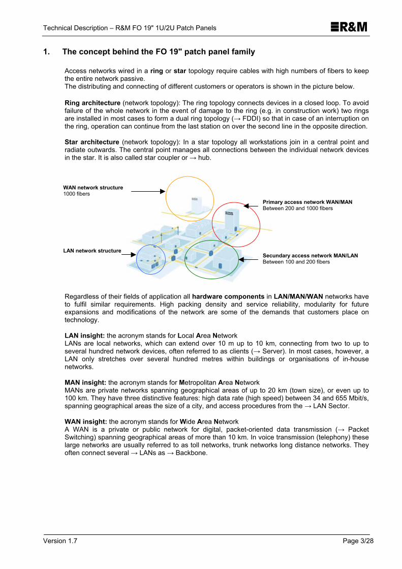
Access networks wired in a ring or star topology require cables with high numbers of fibers to keep the entire network passive. The distributing and connecting of different customers or operators is shown in the picture below.
Ring architecture (network topology): The ring topology connects devices in a closed loop. To avoid failure of the whole network in the event of damage to the ring (e.g. in construction work) two rings are installed in most cases to form a dual ring topology (→ FDDI) so that in case of an interruption on the ring, operation can continue from the last station on over the second line in the opposite direction. Star architecture (network topology): In a star topology all workstations join in a central point and radiate outwards. The central point manages all connections between the individual network devices in the star. It is also called star coupler or → hub.
Regardless of their fields of application all hardware components in LAN/MAN/WAN networks have to fulfil similar requirements. High packing density and service reliability, modularity for future expansions and modifications of the network are some of the demands that customers place on technology.
LAN insight: the acronym stands for Local Area Network LANs are local networks, which can extend over 10 m up to 10 km, connecting from two to up to several hundred network devices, often referred to as clients (→ Server). In most cases, however, a LAN only stretches over several hundred metres within buildings or organisations of in-house networks. MAN insight: the acronym stands for Metropolitan Area Network MANs are private networks spanning geographical areas of up to 20 km (town size), or even up to 100 km. They have three distinctive features: high data rate (high speed) between 34 and 655 Mbit/s, spanning geographical areas the size of a city, and access procedures from the → LAN Sector. WAN insight: the acronym stands for Wide Area Network A WAN is a private or public network for digital, packet-oriented data transmission (→ Packet Switching) spanning geographical areas of more than 10 km. In voice transmission (telephony) these large networks are usually referred to as toll networks, trunk networks long distance networks. They often connect several → LANs as → Backbone.
Primary access network WAN/MAN Between 200 and 1000 fibers
WAN network structure 1000 fibers
Secundary access network MAN/LAN Between 100 and 200 fibers
LAN network structure

Technical Description – R&M FO 19" 1U/2U Patch Panels
Version 1.7 Page 4/28
R&M provides a wide range of passive components for LAN, MAN, and WAN networks. The here described patch panel family in its modular design already covers a great many of applications.
In modern cable networks it is increasingly important to include reserve fibers for a planned network extension at a later point. By using R&M's 19" patch panels a later access to reserve fibers is made easy and convenient.
1.1. Network levels
Connecting level On the connecting level the trunk cables are the direct connections between the local exchanges. As a rule access to passive components is not included in the planning. All fibers of a loose tube of the cable are deposited in a 12er splice tray. The ideal components for the connecting level provided by R&M are: All FO 19" patch panels combined with the standard splice tray R30 or the multifunction module R40.
Branching level On the branching level 19" patch panels protect splices between main high fiber count cables and medium fiber count tap-off cables at the connection points. Here too, access to passive components is usually not included in the planning. The ideal components for the branching level provided by R&M are: All FO 19" patch panels combined with the standard splice tray R30 or the multifunction module R40.
Distributing level On this level 19" components form the connections between the medium fiber count tap-off cables and the low fiber count distribution cables. The distribution cables are led to the network endpoints or directly to the individual users. Here, a fiber optic management is absolutely crucial – R&M offers such a system philosophy. The ideal components for the distributing level provided by R&M are: All FO 19" patch panels combined with the FOM splice tray.
1.2. Schematic view
Primary Network Secondary Network Connecting level Branching level Distributing level

Technical Description – R&M FO 19" 1U/2U Patch Panels
Version 1.7 Page 5/28
1.3. Cabling example with R&M 19" products
The thorough planning of a structured cabling system represents a big challenge for planners, installers and users. The following example shows four floors of a building. On one of the floors the building distributor is located, in accordance with the rules of structured cabling systems. In our example it is the ground floor. In a star topology this distributor connects all the other floors over fiber optic cables, their termination being the 19" floor distributors on the individual floors.
2. Standard and high quality assortment
R&M now offers two options in the 19" technology, the standard assortment and the high quality assortment. Thanks to our international know-how in research, development and manufacturing, our well-engineered and economically sound 19" products do an excellent job, every day, everywhere in the world.
2.1. Standard solutions for the economical user
The new 19" 1U splice box/break-out box perfectly combines functionality and cost effectiveness. It is used to build up fiber optic distributors on the basis of 19" technology. The splice box is used whenever a sliding drawer is not absolutely necessary.
2.2. High quality solutions for maximum operational reliability
The basis of R&M's UniRacks, AirRacks, FibereasyRacks, FOMRacks and Racks R40 is a recessed, smoothly adjustable 19" slide-in unit. Both the loose tube tray and the splice tray plate (splice versions) slide out and can be taken off. Different types of front panels are available featuring different numbers of breakouts. Advantages of the high quality solutions: • Controlled fiber depositing in the R&M patch panels and splice trays for trouble-free
modifications • Large fiber reserve for repeated follow-up splicing • Quick and safe identification in all deposits saves time and nerves • Good accessibility for service and repair work makes the job of the installer easier
FO 19" floor distributor. Interface to the horizontal cabling FO 19" Foccos or 19" wall distributor with FO 19" 1U splice box or 19" 1U break-out box, equipped with ST, SC or SC Duplex.
FO 19" building distributor FO 19" Foccos or 19" FOM cabinet with 19" 1U UniRack or 19" 1U Fibereasy rack, equipped with ST, SC or SC Duplex.
FO indoor cable laid in cable duct

Technical Description – R&M FO 19" 1U/2U Patch Panels
Version 1.7 Page 6/28
2.3. Splice versions
Standard assortment
High quality assortment
FO 19" 1 splice box FO 19" 1U/2U UniRack 5)
FO 19" 1U/2U FOMRack 1)
FO 19" 1U/2U Rack R40
Applications LAN, industrial applications
Telecom, LAN, MAN, CATV, railway, industrial applications
Telecom, MAN, CATV, railway
Telecom, MAN, CATV, railway
Features Non-sliding* Recessed, smoothly adjustable slide-in unit
Recessed, smoothly adjustable slide-in unit
Recessed, smoothly adjustable slide-in unit
Dimensions (w x d x h)
482.6 x 44 x 230 (1U) 482.6 x 44 x 230 (1U) 482.6 x 88 x 230 (2U)
482.6 x 44 x 230 (1U) 482.6 x 88 x 230 (2U)
482.6 x 44 x 230 (1U) 482.6 x 88 x 230 (2U)
Material, colour Sheet steel, powder-coated, median grey, NCS 2502-B Terminations Connector type E-2000 si Connector type SC si Connector type FC Connector type ST Connector type SC duz Connector type E-2000 Compact Connector type SC-RJ
- 24 2), 36 3) - 24 2) 24 2), 36 3) - -
1U = 24 2), 2U = 72 3) 1U = 24 2), 2U = 72 3) 1U = 24 2), 2U = 48 3) 1U = 24 2), 2U = 48 3) 1U = 12 2), 2U = 24 3) 1U = 12 2), 2U = - 1U = 122) , 2U = -
1U = 24, 2U = 24 2) 1U = 24, 2U = 24 2) - - - - -
1U = 24, 2U = 24 2) 1U = 24, 2U = 24 2) - - - - -
Radius splice trays >30 mm >30 mm >32mm >40 mm Splice trays per cable termination
up to 4 1U = 2 2U = 6
1U = 1 2U = 2
1U = 1 2U = 2
Sufficient fiber reserve for repeated follow-up splicing
Yes Yes Yes Yes
Cable exits at patch cable side
Left and right Left and right Left Left
Controlled fiber depositing in splice tray
Good Good Very good Good
Easy identification of fibers in splice tray
Good Good Very good Good
Good accessibility for service and repair work
Average Very good Very good Very good
Application in high speed distribution networks
Average Good Very good Very good
FO cable guide 75mm4) Yes Yes Yes Yes FO cable guide 110mm4) Yes Yes Yes Yes FO FOM cable guide 110mm4)
Yes Yes Yes Yes
FO 21" 1U adapter4) Yes Yes Yes Yes FO patching rings 35 and 75 mm4)
Yes Yes Yes Yes
FO rear cable entry II4) Yes Yes Yes Yes FO rear cable entry with PG16 screwing4)
Yes Yes Yes Yes
FO radius guard4) No No No No FO splice set for 19" 1U splice box4)
Yes No No No
FO cover for 19" 1U splice box / break-out box4)
Yes No No No

Technical Description – R&M FO 19" 1U/2U Patch Panels
Version 1.7 Page 7/28
2.4. Break-out versions
Standard assortment High quality assortment FO 19" 1U Break-out box FO 19" 1U FibereasyRack Applications LAN, industrial applications Telecom, LAN, MAN, CATV, railway, industrial
applications Features Non-sliding Recessed, smoothly adjustable slide-in unit Dimensions (w x d x h) 482.6 x 44 x 230 (1U) 482.6 x 44 x 230 (1U) Material, colour Sheet steel, powder-coated, median grey, NCS 2502-B Terminations Connector type E-2000 si Connector type SC si Connector type FC Connector type ST Connector type SC duz Connector type E-2000 Compact Connector type SC-RJ
- 24 2), 36 3) - 24 2) 24 2), 36 3) - -
24 2) 24 2) 24 2) 24 2) 12 2) 12 2) 12 2)
Cabling systems (terminated installation cables)
Possible Possible
FO cable guide 75mm4) Yes Yes FO cable guide 110mm4) Yes Yes FO FOM cable guide 110mm4)
Yes Yes
FO patching rings 35 and 75 mm4)
Yes Yes
FO 21" 1U adapter4) Yes Yes FO rear cable entry II4) Yes No FO rear cable entry with PG16 screwing4)
Yes No
FO radius guard4) Yes Yes FO cover for 19" 1U splice box / break-out box4)
Yes No
1) Only possible with crimp splice protection 2) Included in the standard assortment 3) Available for an additional charge 4) Option 5) FO 19" 1U AirRack is similar to the 19" 1U UniRack. The only difference is the perforated plate.
3. Standard assortment 19" 1U splice box
3.1. System description 19" 1U splice box
The basis of the 19" 1U splice box is a fixed 19” 1U assembly unit. The installation cable can enter either at the side or at the back of the 1U rack. The installation cables and pigtail fiber reserves can be deposited in the generously designed drawer.

Technical Description – R&M FO 19" 1U/2U Patch Panels
Version 1.7 Page 8/28
3.2. Accessories (options)
Product name R&M ordering number Description FO cable guide (75 mm or 110 mm)
R30315 (75mm), R302003 (110mm)
FO patching rings (35 mm and 75 mm) left and right
R302004 (35mm), R302005 (75mm)
Both the cable guide and the patching rings plus Velcro fastener serve as cable track for the patch cables led to the front panel from left or right.
FO FOM cable guide 110 mm R304439 FO FOM patching rings 75 mm left and right
R304440 Both the FOM cable guide and the FOM patching rings with strain relief elastics serve as cable track for patch cables led to the front panel from left or right.
FO cover for splice box / break-out box
R306775 For protection from mechanical damage. The cover can be opened and locked without tools.
FO 21" 1U adapter set for 19" 1U and 2U patch panels
R305148 With this adapter the 19" patch panels can be fastened in metrical profile rails (535 mm).
FO rear cable guide II for 19" 1U and 2U patch panels
R302058 The rear cable guide is an additional guide for the FO cable and flex hoses.
FO rear cable entry with PG 16 screwing
R302006 This cable entry provides additional strain relief for the FO cable.
FO splice set for 19" 1U splice box R306774 Splice set for empty splice boxes
3.3. R&M's FO 19" 1U splice boxes feature:
• 19" 1U FO assembly unit for fixed installation • Reserve drawer for the incoming installation cable and pigtails • Removable front panel for easy mounting of adapters • Twist-safe holder for up to 4 splice trays • Optional cable entry (straight/angled) • Clear and professional front panel labelling with silk-screen printing • Labelling strips
3.4. The following splice trays can be used:
Standard splice tray with radius 30 mm
Multifunction module with radius 40 mm
FOM (Fiber Optic Management) splice tray with radius 32 mm
FO 19" 1U splice box Yes Not available Not available
3.5. FO 19" 1U splice box
Technical Description – R&M FO 19" 1U/2U Patch Panels
Version 1.7 Page 9/28
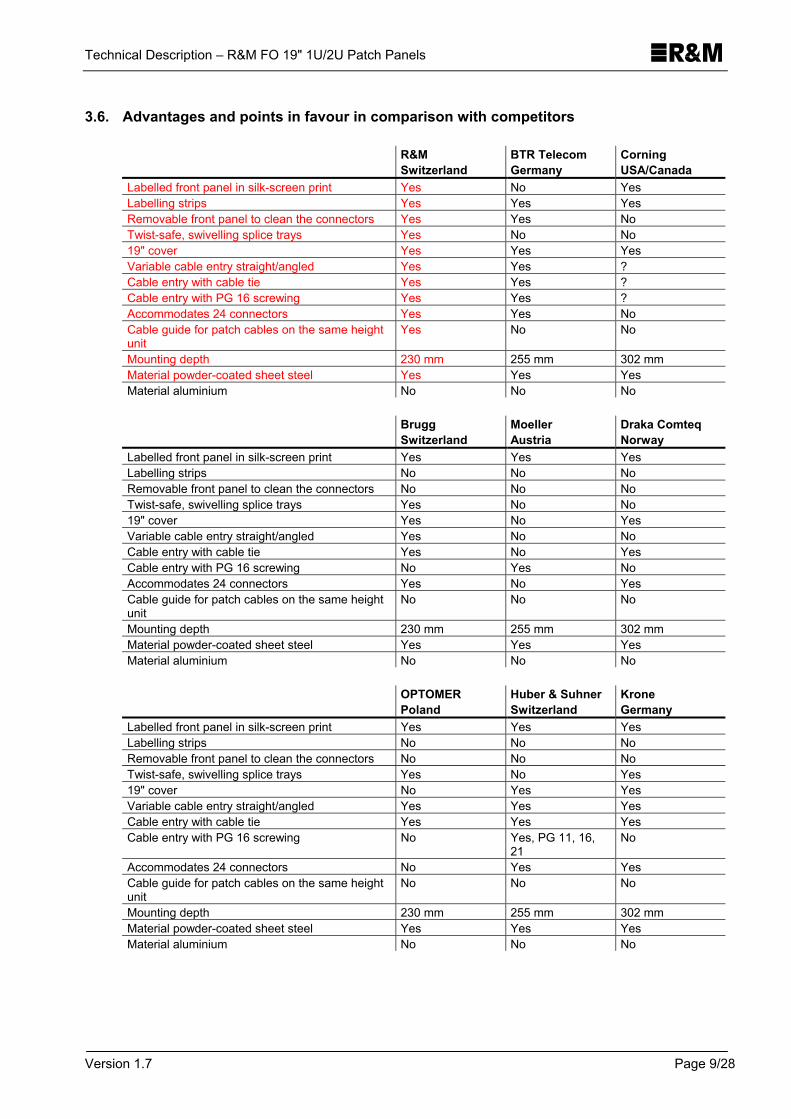
3.6. Advantages and points in favour in comparison with competitors
R&M Switzerland
BTR Telecom Germany
Corning USA/Canada
Labelled front panel in silk-screen print Yes No Yes Labelling strips Yes Yes Yes Removable front panel to clean the connectors Yes Yes No Twist-safe, swivelling splice trays Yes No No 19" cover Yes Yes Yes Variable cable entry straight/angled Yes Yes ? Cable entry with cable tie Yes Yes ? Cable entry with PG 16 screwing Yes Yes ? Accommodates 24 connectors Yes Yes No Cable guide for patch cables on the same height unit
Yes No No
Mounting depth 230 mm 255 mm 302 mm Material powder-coated sheet steel Yes Yes Yes Material aluminium No No No
Brugg
Switzerland Moeller Austria
Draka Comteq Norway
Labelled front panel in silk-screen print Yes Yes Yes Labelling strips No No No Removable front panel to clean the connectors No No No Twist-safe, swivelling splice trays Yes No No 19" cover Yes No Yes Variable cable entry straight/angled Yes No No Cable entry with cable tie Yes No Yes Cable entry with PG 16 screwing No Yes No Accommodates 24 connectors Yes No Yes Cable guide for patch cables on the same height unit
No No No
Mounting depth 230 mm 255 mm 302 mm Material powder-coated sheet steel Yes Yes Yes Material aluminium No No No
OPTOMER
Poland Huber & Suhner Switzerland
Krone Germany
Labelled front panel in silk-screen print Yes Yes Yes Labelling strips No No No Removable front panel to clean the connectors No No No Twist-safe, swivelling splice trays Yes No Yes 19" cover No Yes Yes Variable cable entry straight/angled Yes Yes Yes Cable entry with cable tie Yes Yes Yes Cable entry with PG 16 screwing No Yes, PG 11, 16,
21 No
Accommodates 24 connectors No Yes Yes Cable guide for patch cables on the same height unit
No No No
Mounting depth 230 mm 255 mm 302 mm Material powder-coated sheet steel Yes Yes Yes Material aluminium No No No

Technical Description – R&M FO 19" 1U/2U Patch Panels
Version 1.7 Page 10/28
4. Standard assortment 19" 1U break-out box
4.1. System description 19" 1U break-out box
The basis of the 19" 1U break-out box is a fixed 19” 1U assembly unit. The break-out cable can enter either at the side or at the back of the 1U rack. The break-out cables and pigtail reserves can be deposited in the generously designed drawer.
4.2. Accessories (options)
Product name R&M ordering number Description FO cable guide (75 mm or 110 mm)
R30315 (75mm), R302003 (110mm)
FO patching rings (35 mm and 75 mm) left and right
R302004 (35mm), R302005 (75mm)
Both the cable guide and the patching rings plus Velcro fastener serve as cable track for the patch cables led to the front panel from left or right.
FO FOM cable guide 110mm R304439
FO FOM patching rings 75 mm left and right
R304440
Both the FOM cable guide and the FOM patching rings with strain relief elastics serve as cable track for patch cables led to the front panel from left or right.
FO cover for splice box / break-out box
R306775 For protection from mechanical damage. The cover can be opened and locked without tools.
FO 21" 1U adapter set for 19" 1U and 2U patch panels
R305148 With this adapter the 19" patch panels can be fastened in metrical profile rails (535 mm).
FO rear cable guide II for 19" 1U and 2U patch panels
R302058 The rear cable guide is an additional guide for the FO cable and flex hoses.
FO rear cable entry with PG 16 screwing
R302006 This cable entry provides additional strain relief for the FO cable.
FO radius guard 2x15mm R302007 Additional patch cable guide. The break-out box accommodates max. two times 2x15mm radius guards.
4.3. R&M's FO 19" 1U break-out boxes feature:
• 19" 1U FO assembly unit for fixed installation • Reserve drawer for the incoming break-out cable • Removable front panel for easy mounting of adapters • Variable cable entry (straight/angled) • Clear and professional front panel labelling with silk-screen printing • Labelling strips
4.4. FO 19" 1U break-out box

Technical Description – R&M FO 19" 1U/2U Patch Panels
Version 1.7 Page 11/28
4.5. Advantages and points in favour in comparison with competitors
R&M Switzerland
BTR Telecom Germany
Corning USA/Canada
Labelled front panel in silk-screen print Yes No Yes Labelling strips Yes Yes Yes Removable front panel to clean the connectors Yes Yes No 19" cover Yes Yes Yes Variable cable entry straight/angled Yes Yes ? Cable entry with cable tie Yes Yes ? Cable entry with PG 16 screwing Yes Yes ? Accommodates 24 connectors Yes Yes No Mounting of pre-terminated cables Yes Yes Yes Cable guide for patch cables on the same height unit
Yes No No
Mounting depth 230 mm 255 mm 302 mm Material powder-coated sheet steel Yes Yes Yes Material aluminium No No No
Brugg
Switzerland Moeller Austria
Draka Comteq Norway
Labelled front panel in silk-screen print Yes Yes Yes Labelling strips No No No Removable front panel to clean the connectors No No No 19" cover Yes No Yes Variable cable entry straight/angled Yes No No Cable entry with cable tie Yes No Yes Cable entry with PG 16 screwing No Yes No Accommodates 24 connectors Yes No Yes Mounting of pre-terminated cables Yes Yes Yes Cable guide for patch cables on the same height unit
No No No
Mounting depth 230 mm 255 mm 302 mm Material powder-coated sheet steel Yes Yes Yes Material aluminium No No No
OPTOMER
Poland Huber & Suhner Switzerland
Krone Germany
Labelled front panel in silk-screen print Yes Yes Yes Labelling strips No No No Removable front panel to clean the connectors No No No 19" cover No Yes Yes Variable cable entry straight/angled Yes Yes Yes Cable entry with cable tie Yes Yes Yes Cable entry with PG 16 screwing No Yes, PG 11, 16,
21 No
Accommodates 24 connectors No Yes Yes Mounting of pre-terminated cables Yes Yes Yes Cable guide for patch cables on the same height unit
No No No
Mounting depth 230 mm 255 mm 302 mm Material powder-coated sheet steel Yes Yes Yes Material aluminium No No No

Technical Description – R&M FO 19" 1U/2U Patch Panels
Version 1.7 Page 12/28
5. High quality assortment 19" 1U UniRack, FOMRack, Rack R40
5.1. System description 19" 1U UniRack, FOMRack, Rack R40
The basis of the 19" 1U high quality assortment consists of a smoothly retractable 19'' 1U slide-in unit (retractable 0 to 55 mm). The installation cable may enter the 1U rack at the side or at the rear. The cable guide for the rear cable entry, however, is optional. Up to 2 x 2.0 meter of spare loose tubes can be stored in the generously designed drawer. There are two rectangular openings on the left and right in the splice tray plate to lead the loose tubes from the drawer to the splice tray. The pigtail fiber reserve of approx. 3m can be stored in the splice tray plate, i.e. in the splice tray. The observance of the bending radius in the splice tray, i.e. in the R&M 1U Rack is ensured. R&M today offers three types of splice trays, cf. table on page 25, chapter 9. In an extension, the splice tray and the loose tube reserve drawer can be pulled out far enough for the splice tray to be opened with a screwdriver. (Not possible with the patch cable guide of 110mm.) If no vertically retractable splice table is available, the 2 meters of loose tubes reserve can be removed. This allows a handling of the splice unit within a radius of 1 meter.
5.2. Accessories (options)
Product name R&M ordering number Description FO cable guide (75 mm or 110 mm)
R30315 (75mm), R302003 (110mm) The cable guide plus Velcro fastener serves as cable track for the patch cables led to the front panel from left or right.
FO patching rings (35 mm and 75 mm) left and right
R302004 (35mm), R302005 (75mm) The patching rings plus Velcro fastener serve as cable track for the patch cables led to the front panel from left or right. This is the case when the 1U UniRack is moved back (smoothly adjustable in depth to 55 mm).
FO FOM cable guide 110mm R304439 The FOM cable guide with strain relief elastics serve as cable track/ for patch cables led to the front panel from left or right.
FO FOM patching rings 75 mm left and right
R304440 The FOM patching rings with strain relief elastics serve as cable track for patch cables led to the front panel from left or right. This is the case when the 1U UniRack is moved back (smoothly adjustable in depth to 55 mm).
FO 21" 1U adapter set for 19" 1U and 2U patch panels
R305148 With this adapter the 19" patch panels can be fastened in metrical profile rails (535 mm).
FO rear cable guide II for 19" 1U and 2U patch panels
R302058 The rear cable guide is an additional guide for the FO cable and flex hoses.
FO rear cable entry with PG 16 screwing
R302006 This cable entry provides additional relief for the FO cable.

Technical Description – R&M FO 19" 1U/2U Patch Panels
Version 1.7 Page 13/28
5.3. R&M's FO 19" 1U UniRacks, 1U FOMRacks and Racks R40 feature:
• Recessed, smoothly adjustable 1U slide-in unit (range of 55mm) • Reserve drawer for the incoming installation cable • Splice tray plate as splice unit • Removable front panel for easy mounting of adaptors • Twist-safe holder of max. 2 splice trays • Variable cable entry (straight/angled) • Pigtail guide • Clear and professional labelling of the front panel in silks-screen printing • Labelling strips
5.4. The following splice trays can be used:
Standard splice tray with radius 30 mm
Multifunction module with radius 40 mm
FOM (Fiber Optic Management) splice tray with radius 32 mm
FO 19" 1U UniRack Yes Not available Not available FO 19" 1U FOMRack Not available Not available Yes FO 19" 1U Rack R40 Not available Yes Not available
5.5. FO 19" 1U UniRack
5.6. FO 19" 1U Rack R40
Standard splice tray with radius 30 mm
Multifunction module with radius 40 mm

Technical Description – R&M FO 19" 1U/2U Patch Panels
Version 1.7 Page 14/28
5.7. FO 19" 1U FOMRack
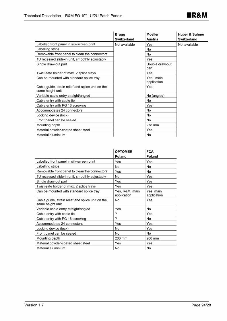
5.8. Advantages and points in favour in comparison with competitors
R&M Switzerland
BTR Telecom Germany
Corning USA/Canada
Labelled front panel in silk-screen print Yes No Yes Labelling strips Yes Yes Yes Removable front panel to clean the connectors Yes Yes No 1U recessed slide-in unit, smoothly adjustably Yes Yes No Pigtail reserves and the incoming installation cables are separate (two separate deposits)
Yes Yes No
Double draw-out part Yes No No Twist-safe holder of max. 2 splice trays Yes Yes Yes Standard splice tray Yes Yes Yes Multifunction module with radius 40 mm Yes No ? Single fiber management in splice tray Yes No ? Coloured pigtails acc. to code DIN VDE 0888 with the connector types LSH and SC SM
Yes No No
3 meters pigtail reserves (1.7 meters of it inside the splice tray)
Yes Yes Yes
Cable guide, strain relief and splice unit are on the same height unit
Yes No No
Variable cable entry straight/angled Yes Yes ? Cable entry with cable tie Yes Yes ? Cable entry with PG 16 screwing Yes Yes ? Accommodates up to 24 connectors Yes Yes Yes Locking device (lock) No No Yes Front panel can be sealed Yes No No Mounting depth 230 mm 255 mm 363 mm Material powder-coated sheet steel Yes Yes Yes Material aluminium No No No
FOM (Fiber Optic Management) splice tray with radius 32 mm

Technical Description – R&M FO 19" 1U/2U Patch Panels
Version 1.7 Page 15/28
Brugg
Switzerland Moeller Austria
Huber & Suhner Switzerland
Labelled front panel in silk-screen print Yes No No Labelling strips No Yes Yes Removable front panel to clean the connectors No No No 1U recessed slide-in unit, smoothly adjustably Yes Yes Yes Pigtail reserves and the incoming installation cables are separate (two separate deposits)
Yes No No
Double draw-out part No Yes No Twist-safe holder of max. 2 splice trays Yes Yes Yes Standard splice tray Yes Yes Yes, R&M Multifunction module with radius 40 mm No Yes No Single fiber management in splice tray No No No Coloured pigtails acc. to code DIN VDE 0888 with the connector types LSH and SC SM
No No No
3 meters pigtail reserves (1.7 meters of it inside the splice tray)
Yes No No
Cable guide, strain relief and splice unit are on the same height unit
No Yes No
Variable cable entry straight/angled Yes No (angled) Yes Cable entry with cable tie Yes No Yes Cable entry with PG 16 screwing ? Yes Yes, PG 11, 16, 21 Accommodates up to 24 connectors Yes Yes Yes Locking device (lock) No No No Front panel can be sealed No No No Mounting depth 230 mm 278 mm 235 mm Material powder-coated sheet steel No Yes No Material aluminium Yes No Yes
OPTOMER
Poland FCA Poland
Labelled front panel in silk-screen print Yes Yes Labelling strips No No Removable front panel to clean the connectors Yes No 1U recessed slide-in unit, smoothly adjustably No Yes Pigtail reserves and the incoming installation cables are separate (two separate deposits)
No No
Double draw-out part No No Twist-safe holder of max. 2 splice trays Yes Yes Standard splice tray Yes, R&M Yes Multifunction module with radius 40 mm No ? Single fiber management in splice tray Yes No Coloured pigtails acc. to code DIN VDE 0888 with the connector types LSH and SC SM
No No
3 meters pigtail reserves (1.7 meters of it inside the splice tray)
No No
Cable guide, strain relief and splice unit are on the same height unit
No Yes
Variable cable entry straight/angled Yes No Cable entry with cable tie ? Yes Cable entry with PG 16 screwing ? No Accommodates up to 24 connectors Yes Yes Locking device (lock) No Yes Front panel can be sealed No No Mounting depth 200 mm 200 mm Material powder-coated sheet steel Yes Yes Material aluminium No No

Technical Description – R&M FO 19" 1U/2U Patch Panels
Version 1.7 Page 16/28
6. High quality assortment 19" 1U AirRack
6.1. System description 19" 1U AirRack
The basis of R&M's AirRacks consists of a smoothly retractable 19'' 1U slide-in unit (retractable 0 to 55 mm). The slide-in unit, the cable guide and the splice tray plate are made of perforated plate. The installation cable may enter the AirRack at the side or at the rear. The cable guide for the rear cable entry, however, is optional. Up to 2 x 2.0 meter of spare loose tubes can be stored in the generously designed drawer. There are two rectangular openings on the left and right in the splice tray plate to lead the loose tubes from the drawer to the splice tray. The pigtails reserve of approx. 3m can be stored in the splice tray table, i.e. in the splice tray. The observance of the bending radius in the splice tray, i.e. in the R&M AirRack is ensured. In an extension, the splice tray and the loose tube reserve drawer can be pulled out far enough for the splice tray to be opened with a screwdriver. (Not possible with the patch cable guide of 110mm.) If no vertically retractable splice table is available, the 2 meters of loose tubes reserve can be removed. This allows a handling of the splice unit within a radius of 1 meter.
6.2. Accessories (options)
Product name R&M ordering number Description FO cable guide (75 mm or 110 mm)
R30315 (75mm), R302003 (110mm) The cable guide plus Velcro fastener serves as cable track for the patch cables led to the front panel from left or right.
FO patching rings (35 mm and 75 mm) left and right
R 302004 (35mm), R 302005 (75mm) The patching rings plus Velcro fastener serve as cable track for the patch cables led to the front panel from left or right. This is the case when the 1U AirRack is moved back (smoothly adjustable in depth to 55 mm).
FO FOM cable guide 110mm R304439 The FOM cable guide with strain relief elastics serve as cable track for patch cables led to the front panel from left or right.
FO FOM patching rings 75 mm left and right
R304440 The FOM patching rings with strain relief elastics serve as cable track for patch cables led to the front panel from left or right. This is the case when the 1U AirRack is moved back (smoothly adjustable in depth to 55 mm).
FO rear cable guide II for 19" 1U and 2U patch panels
R302058 The rear cable guide is an additional guide for the FO cable and flex hoses.
FO rear cable entry with PG 16 screwing
R302006 This cable entry provides additional relief for the FO cable.
FO 21" 1U adapter set for 19" 1U and 2U patch panels
R305148 With this adapter the 19" patch panels can be fastened in metrical profile rails (535 mm).

Technical Description – R&M FO 19" 1U/2U Patch Panels
Version 1.7 Page 17/28
6.3. R&M's FO 19" 1U AirRacks feature:
• Recessed, smoothly adjustable 1U AirRack unit (range of 55mm) • AirReserve drawer for the incoming installation cable • AirSplice tray plate as splice unit • Removable front panel for easy mounting of adaptors • Twist-safe holder of max. 2 splice trays • Variable cable entry (straight/angled) • Pigtail guide • Clear and professional labelling of the front panel in silks-screen printing • Labelling strips
6.4. The following splice trays can be used:
Standard splice tray with radius 30 mm
Multifunction module with radius 40 mm
FOM (Fiber Optic Management) splice tray with radius 32 mm
FO 19" 1U AirRack Yes Not available Not available
6.5. FO 19" 1U AirRack
6.6. Advantages and points in favour in comparison with competitors
R&M Switzerland
Sedlbauer AG Germany
Labelled front panel in silk-screen print Yes No Labelling strips Yes Yes Removable front panel to clean the connectors Yes No 1U recessed slide-in unit, smoothly adjustably Yes Yes, (2U) Pigtail reserves and the incoming installation cables are separate (two separate deposits)
Yes Yes
Double draw-out part Yes No, swivelling Twist-safe holder of max. 2 splice trays Yes Yes Standard splice tray Yes Yes, R&M Coloured pigtails acc. to code DIN VDE 0888 with the connector types LSH and SC SM
Yes No
3 meter pigtail reserves (1.7 meters of it inside the splice tray)
Yes No
Standard splice tray with radius 30 mm

Technical Description – R&M FO 19" 1U/2U Patch Panels
Version 1.7 Page 18/28
R&M
Switzerland Sedlbauer AG Germany
Variable cable entry straight/angled Yes Yes Cable entry with cable tie Yes ? Cable guide, strain relief and splice unit on the same height unit
Yes Yes
Cable entry with PG 16 screwing Yes ? Accommodates 24 connectors Yes Yes, (2U) Locking device (lock) No No Front panel can be sealed Yes No Mounting depth 210 mm 265 mm Perforated plate Yes Yes Material powder-coated sheet steel Yes Yes Material aluminium No No
7. High quality assortment 19" 2U UniRack, FOMRack, Rack R40
7.1. System description 19" 2U UniRack, FOMRack, Rack R40
The basis of the 19" 2U high quality assortment consists of a smoothly retractable 19'' 2U slide-in unit (retractable 0 to 55 mm). The installation cable may enter the 2U rack at the side or at the rear. The cable guide for the rear cable entry, however, is optional. Up to 6 x 2.0 meter of spare loose tubes can be stored in the generously designed drawer. There are two rectangular openings on the left and right in the splice tray plate to lead the loose tubes from the drawer to the splice tray. The pigtails reserve of approx. 3m can be stored in the splice tray table, i.e. in the splice tray. The observance of the bending radius in the splice tray, i.e. in the R&M 2U Rack is ensured. R&M today offers three types of splice trays, cf. table on page 25, chapter 9. In an extension, the splice tray and the loose tube reserve drawer can be pulled out far enough for the splice tray to be opened with a screwdriver. (Not possible with the patch cable guide of 110mm.) If no vertically retractable splice table is available, the 2 meters of loose tubes reserve can be removed. This allows a handling of the splice unit within a radius of 1 meter.
7.2. Accessories (options)
Product name R&M ordering number Description FO cable guide 110 mm
R302003 The cable guide plus Velcro fastener serves as cable track for the patch cables led to the front panel from left or right.
FO patching rings 75 mm, left and right
R302005 The patching rings plus Velcro fastener serve as cable track for the patch cables led to the front panel from left or right. This is the case when the 2U UniRack is moved back (smoothly adjustable in depth to 55 mm).
FO FOM cable guide 110 mm R304439 The FOM cable guide with strain relief elastics serve as cable track for patch cables led to the front panel from left or right.

Technical Description – R&M FO 19" 1U/2U Patch Panels
Version 1.7 Page 19/28
Product name R&M ordering number Description FO 21" 1U adapter set for 19" 1U and 2U patch panels
R305148 With this adapter the 19" patch panels can be fastened in metrical profile rails (535 mm).
FO FOM patching rings 75 mm left and right
R304440 The FOM patching rings with strain relief elastics serve as cable track for patch cables led to the front panel from left or right. This is the case when the 1U AirRack is moved back (smoothly adjustable in depth to 55 mm).
FO rear cable guide II for 19" 1U and 2U patch panels
R302058 The rear cable guide is an additional guide for the FO cable and flex hoses.
FO rear cable entry with PG 16 screwing
R302006 This cable entry provides additional relief for the FO cable.
7.3. R&M's FO 19" 2U UniRacks feature:
• Recessed, smoothly adjustable 2U slide-in unit (range of 55mm) • Reserve drawer for the incoming installation cable • Splice tray plate as splice unit • Removable front panel for easy mounting of adaptors • Twist-safe holder of max. 6 splice trays • Variable cable entry (straight/angled) • Pigtail guide • Clear and professional labelling of the front panel in silks-screen printing • Labelling strips
7.4. The following splice trays can be used:
Standard splice tray with radius 30 mm
Multifunction module with radius 40 mm
FOM (Fiber Optic Management) splice tray with radius 32 mm
FO 19" 2U UniRack Yes Not available Not available FO 19" 2U FOMRack Not available Not available Yes FO 19" 2U Rack R40 Not available Yes Not available
7.5. FO 19" 2U UniRack
Standard splice tray with radius 30 mm

Technical Description – R&M FO 19" 1U/2U Patch Panels
Version 1.7 Page 20/28
7.6. FO 19" 2U Rack R40
7.7. FO 19" 2U FOMRack
7.8. Advantages and points in favour in comparison with competitors
R&M Switzerland
BTR Telecom Germany
Corning USA/Canada
Labelled front panel in silk-screen print Yes Yes Labelling strips Yes Yes Removable front panel to clean the connectors Yes No 2U recessed slide-in unit, smoothly adjustably Yes No Pigtail reserves and the incoming installation cables are separate (two separate deposits)
Yes No
Double draw-out part Yes No Twist-safe holder of max. 6 splice trays Yes No, 4 Standard splice tray Yes Yes Multifunction module with radius 40 mm Yes ? Single fiber management in splice tray Yes No Coloured pigtails acc. to code DIN VDE 0888 with the connector types LSH and SC SM
Yes No
3 meters pigtail reserves (1.7 meters of it inside the splice tray)
Yes Yes
Cable guide, strain relief and splice unit on the same height unit
Yes
Not available
No
Multifunction module with radius 40 mm
FOM (Fiber Optic Management) Splice tray with radius 32 mm

Technical Description – R&M FO 19" 1U/2U Patch Panels
Version 1.7 Page 21/28
R&M
Switzerland BTR Telecom Germany
Corning USA/Canada
Variable cable entry straight/angled Yes ? Cable entry with cable tie Yes ? Cable entry with PG 16 screwing Yes ? Accommodates up to 72 connectors Yes No Locking device (lock) No Yes Front panel can be sealed Yes No Mounting depth 230 mm 363 mm Material powder-coated sheet steel Yes Yes Material aluminium No
Not available
No
Brugg Switzerland
Moeller Austria
Sedlbauer AG Germany
Labelled front panel in silk-screen print Yes No No Labelling strips No Yes Yes Removable front panel to clean the connectors No No No 2U recessed slide-in unit, smoothly adjustably Yes Yes Yes Pigtail reserves and the incoming installation cables are separate (two separate deposits)
Yes No Yes
Double draw-out part No Yes No, swivelling Twist-safe holder of max. 6 splice trays No No Yes Standard splice tray Yes Yes Yes, R&M Multifunction module with radius 40 mm No Yes No Single fiber management in splice tray No No Yes, Krone Coloured pigtails acc. to code DIN VDE 0888 with the connector types LSH and SC SM
No No No
3 meters pigtail reserves (1.7 meters of it inside the splice tray)
Yes No No
Cable guide, strain relief and splice unit on the same height unit
No Yes Yes
Variable cable entry straight/angled Yes No (angled) Yes Cable entry with cable tie Yes No ? Cable entry with PG 16 screwing ? Yes ? Accommodates up to 72 connectors No No No Locking device (lock) No No No Front panel can be sealed No No No Mounting depth 274 mm 278 mm 275 mm Material powder-coated sheet steel No Yes Yes Material aluminium Yes No No
OPTOMER
Poland FCA Poland
Huber & Suhner Switzerland
Labelled front panel in silk-screen print Yes Yes No Labelling strips No No Yes Removable front panel to clean the connectors Yes No No 2U recessed slide-in unit, smoothly adjustably No Yes Yes Pigtail reserves and the incoming installation cables are separate (two separate deposits)
No No No
Double draw-out part No No No Twist-safe holder of max. 6 splice trays No, 4 No Yes Standard splice tray Yes, R&M Yes Yes, R&M Multifunction module with radius 40 mm No ? No Single fiber management in splice tray Yes No No Coloured pigtails acc. to code DIN VDE 0888 with the connector types LSH and SC SM
No No No

Technical Description – R&M FO 19" 1U/2U Patch Panels
Version 1.7 Page 22/28
OPTOMER Poland
FCA Poland
Huber & Suhner Switzerland
3 meters pigtail reserves (1.7 meters of it inside the splice tray)
No No No
Cable guide, strain relief and splice unit on the same height unit
No Yes No
Variable cable entry straight/angled Yes No Yes Cable entry with cable tie ? Yes Yes Cable entry with PG 16 screwing ? No Yes, PG 11, 16,
21 Accommodates up to 72 connectors No No No Locking device (lock) No Yes No Front panel can be sealed No No No Mounting depth 200 mm 200 mm 235 mm Material powder-coated sheet steel Yes Yes No Material aluminium No No Yes
8. High quality assortment
8.1. System description 19" 1U FibereasyRack
The basis of the R&M 19” 1U FibereasyRack consists of a continuously adjustable 19'' 1U assembly (retractable 0 to 55 mm). The break-out cable may enter the 1U rack at the side or at the rear. The break-out cables can be stored in the generously dimensioned drawer.
8.2. Accessories (options)
Product name R&M ordering number Description FO cable guide (75 mm or 110 mm)
R30315 (75mm), R302003 (110mm)
FO patching rings (35 mm and 75 mm) left and right
R302004 (35mm), R302005 (75mm)
Both the cable guide and the patching rings plus Velcro fastener serve as cable track for the patch cables led to the front panel from left or right.
FO FOM cable guide 110 mm R304439 FO FOM patching rings 75 mm left and right
R304440 Both the FOM cable guide and the FOM patching rings with strain relief elastics serve as cable track for patch cables led to the front panel from left or right.
FO 21" 1U adapter set for 19" 1U and 2U patch panels
R305148 With this adapter the 19" patch panels can be fastened in metrical profile rails (535 mm).
FO rear cable guide II for 19" 1U and 2U patch panels
R302058 The rear cable guide is an additional guide for the FO cable and flex hoses.
FO rear cable entry with PG 16 screwing
R302006 This cable entry provides additional relief for the FO cable.
FO radius guard 2x15mm R302007 Additional patch cable guide. The break-out box accommodates max. two times 2x15mm radius guards.

Technical Description – R&M FO 19" 1U/2U Patch Panels
Version 1.7 Page 23/28
8.3. R&M's FO 19" 1U FibereasyRack feature:
• Recessed, smoothly adjustable 1U slide-in unit • Reserve drawer for the incoming installation cable • Removable front panel for easy mounting of adaptors • Twist-safe holder of max. 2 splice trays • Variable cable entry (straight/angled) • Clear and professional labelling of the front panel in silks-screen printing • Labelling strips
8.4. FO 19" 1U FibereasyRack
8.5. Advantages and points in favour in comparison with competitors
R&M Switzerland
BTR Telecom Germany
Corning USA/Canada
Labelled front panel in silk-screen print Yes Yes Labelling strips Yes Yes Removable front panel to clean the connectors Yes No 1U recessed slide-in unit, smoothly adjustably Yes No Single draw-out part Yes Yes Twist-safe holder of max. 2 splice trays Yes Yes Can be mounted with standard splice tray Yes, break-out
version as of now Yes, main applications
Cable guide, strain relief and splice unit on the same height unit
Yes No
Variable cable entry straight/angled Yes ? Cable entry with cable tie Yes ? Cable entry with PG 16 screwing Yes ? Accommodates 24 connectors Yes Yes Locking device (lock) No Yes Front panel can be sealed Yes No Mounting depth 230 mm 363 mm Material powder-coated sheet steel Yes Yes Material aluminium No
Not available
No
Technical Description – R&M FO 19" 1U/2U Patch Panels
Version 1.7 Page 24/28
Brugg
Switzerland Moeller Austria
Huber & Suhner Switzerland
Labelled front panel in silk-screen print Yes Labelling strips No Removable front panel to clean the connectors No 1U recessed slide-in unit, smoothly adjustably Yes Single draw-out part Double draw-out
part Twist-safe holder of max. 2 splice trays Yes Can be mounted with standard splice tray Yes, main
application Cable guide, strain relief and splice unit on the same height unit
Yes
Variable cable entry straight/angled No (angled) Cable entry with cable tie No Cable entry with PG 16 screwing Yes Accommodates 24 connectors No Locking device (lock) No Front panel can be sealed No Mounting depth 278 mm Material powder-coated sheet steel Yes Material aluminium
Not available
No
Not available
OPTOMER Poland
FCA Poland
Labelled front panel in silk-screen print Yes Yes Labelling strips No No Removable front panel to clean the connectors Yes No 1U recessed slide-in unit, smoothly adjustably No Yes Single draw-out part Yes Yes Twist-safe holder of max. 2 splice trays Yes Yes Can be mounted with standard splice tray Yes, R&M, main
application Yes, main application
Cable guide, strain relief and splice unit on the same height unit
No Yes
Variable cable entry straight/angled Yes No Cable entry with cable tie ? Yes Cable entry with PG 16 screwing ? No Accommodates 24 connectors Yes Yes Locking device (lock) No Yes Front panel can be sealed No No Mounting depth 200 mm 200 mm Material powder-coated sheet steel Yes Yes Material aluminium No No

Technical Description – R&M FO 19" 1U/2U Patch Panels
Version 1.7 Page 25/28
9. R&M splice trays
Standard splice tray with radius 30 mm
Multifunction module with radius 40 mm
FOM (Fiber Optic Management) splice tray with radius 32 mm
Fiber reserve sufficient for repeated follow-up splicing
Yes Yes Yes
Controlled fiber deposit inside the splice tray
Good Goode Very good
Fibers in splice tray can be easily identified
Good Good Very good
Easy access for service and repair work
Yes Yes Yes
Application in high-speed distribution networks
Good Very good Very good
Little mounting time Yes Yes No (time-consuming) Splice tray cover Yes, plastic Yes, plastic transparent Yes, aluminium
9.1. Standard splice tray radius 30 mm
9.2. Multifunction module radius 40 mm

Technical Description – R&M FO 19" 1U/2U Patch Panels
Version 1.7 Page 26/28
9.3. FOM (Fiber Optic Management), splice tray radius 32 mm
10. Material specifications
10.1. FO 19" 1U/2U patch panels
• 1U assembly unit Sheet steel 1.5 mm powder-coated median grey, NCS 2502-B • 2U assembly unit Sheet steel 1.5 mm powder-coated median grey, NCS 2502-B • 1U AirSlide-in unit Sheet steel 1.5 mm powder-coated median grey, NCS 2502-B • 19” 1U mounting brackets Sheet steel 1.5 mm powder-coated median grey, NCS 2502-B • 19” 2U mounting brackets Sheet steel 1.5 mm powder-coated median grey, NCS 2502-B • Loose tube drawer Sheet steel 1.5 mm powder-coated median grey, NCS 2502-B • AirLoose tube drawer Sheet steel 1.5 mm powder-coated median grey, NCS 2502-B • 1U splice tray plate Sheet steel 1.5 mm powder-coated median grey, NCS 2502-B • 1U AirSplice tray plate Sheet steel 1.5 mm powder-coated median grey, NCS 2502-B • Front panel Sheet steel 1.5 mm powder-coated median grey, NCS 2502-B • Cable guide Sheet steel 1.5 mm powder-coated median grey, NCS 2502-B 75 and 110 mm • Patching rings 35 mm Sheet steel 1.5 mm powder-coated median grey, NCS 2502-B • Patching rings 75 mm Sheet steel 1.5 mm powder-coated median grey, NCS 2502-B • Rear cable guides Rough aluminium
10.2. Dimensions in mm
FO 19" 1U patch panels FO 19" 2U patch panels

Technical Description – R&M FO 19" 1U/2U Patch Panels
Version 1.7 Page 27/28
10.3. Splice trays
• Standard splice tray r › 30mm, ABS white • Multifunction module r › 40mm, polycarbonate grey • FOM splice tray r › 32mm, ABS grey
11. Accessories
The wide range of available accessories simplifies working with R&M patch panels even more and opens up many cabling and connecting possibilities.
11.1. Splice holders
Depending on the system, our splice holders accommodated up to 12 splice protectors, which are still fastened inside the splice tray.
Product name R&M ordering number Description
FO splice holder ANT R30255 To hold max. 12 ANT splice protections. Material: macrolon, black
FO splice protection ANT R30086 Crimp splice protection for single fibers. Material: sheet plate parts, inside coated with permanently elastic material
FO splice holder Fujikura R30039-06 To hold max. 6 shrink splice protections Material: POM, black
FO splice protection Fujikura R30087 For single fibers, diameter 3 x 65 mm / 3 x 35 mm Material: shrink tube with metal insert
FO splice holder 3M R30042 To hold max. 6 3M Fibrlok splice connections. Material: POM, black
FO splice protection 3M Fiberlok
R30089 Mechanical FO splice connector for 250 µm up to 900 µm pigtail
11.2. FO dummy plug
With dummy plugs unused cut-outs (SC, SC-RJ, E-2000, E-2000 Compact, ST, FC) can be covered.
11.3. FO 19" 1U patch cable tray III
In each 19" 1U patch cable tray up to 50 meters of patch cables can be deposited.

Technical Description – R&M FO 19" 1U/2U Patch Panels
Version 1.7 Page 28/28
12. Technical descriptions and documentation • Catalogue FO Products English R305470 Katalog FO Products Englisch • Catalogue FO Products German R305469 Katalog FO Produkte Deutsch • PowerPoint presentation Patch Panels German/English Powerpoint Präsentation Rangierfelder • PowerPoint presentation 3U 8HP Fiberliner German/English Powerpoint Präsentation 3HE 8TE Fiberliner • PowerPoint presentation 3HE 7HP Connector Module German/English Powerpoint Präsentation 3HE 7TE Steckermodul • PowerPoint presentation FOMsystem German/English Powerpoint Präsentation FOMsystem • PowerPoint presentation SM Coupler German/English Powerpoint Präsentation SM Koppler • Installation Instructions 19" 1U/2U Patch Panels Splice Version 301982 Bedienungsanleitungen 19" 1HE /2HE Rangierfelder Spleiss Version • Installation Instructions 19" 1U/2U Patch Panels Break-out Version 3939 Bedienungsanleitungen 19" 1HE /2HE Rangierfelder Break-Out-Version • Installation Instructions 19" 1U Splice, Break-out Box 306627 Bedienungsanleitungen 19" 1HE Spleiss-, Break-Out-Box • Installation Instructions Krone FiberPlus 304364 Bedienungsanleitung Krone FiberPlus • Installation Instructions 3U 8 HP Fiberliner Splice Version 3974 Bedienungsanleitung 3HE 8HP Fiberliner Spleiss Version • Installation Instructions 3U 8 HP Fiberliner Break-out Version 3975 Bedienungsanleitung 3HE 8HP Fiberliner Break-Out-Version • Installation Instructions 19" 3U Patch Panels 4291 Bedienungsanleitung 19” 3HE Rangierfelder • Installation Instructions 3U 7 HP Connector Module 305371 Bedienungsanleitung 3HE 7HP Steckermodul • Installation Instructions SM Coupler 306405 Bedienungsanleitung SM Koppler • Installation Instructions FOMsystem 305278 Bedienungsanleitung FOM Schrank • Test Report R&M Patch Panels German/English Prüfbericht R&M Rangierfelder • Technical Description Foccos German/English Technische Beschreibung Foccos • Technical Description Patch Panels German/English Technische Beschreibung Rangierfelder • Technical Description 3 U 8 HP Fiberliner Geman/English Technische Beschreibung 3HE 8TE Fiberliner • Technical Description 3U 7 HP Connector Module German/English Technische Beschreibung 3HE 7TE Steckermodul • Technical Description FOMsystem German/English Technische Beschreibung FOMsytem • Technical Description SM Coupler German/English Technische Beschreibung SM Koppler • Technical Description SM Attenuators, Terminators, Coupling Adapters German/English Technische Beschreibung SM Dämpfungsglieder, Abschluss, Übergangskupplung • Technical Specifications 19" Optical Distribution Frame and 19" Modules German/English Ausschreibungstext für den optischen 19" Verteiler und den 19" Module E-2000 (LSH): Manufactured under licence of Diamond SA, CH-6616 Losone LSH = E-2000 LSHRJ = E-2000 Compact
This document has been drafted with utmost care and reflects the products engineering level at the time of publication. Amendments or corrections to this document will be included in each new edition. Subject to technical change without notice.