Embed Size (px)
Citation preview

Filament Wound High Load Self-Lubricating Bearings
an EnPro Industries company
The Global Leader
in High Performance Bearing Solutions
The GGB AdvantageWith a global manufacturing footprint, including cutting edge R&D facilities, flexible production platforms and extensive customer
support networks, GGB offers unmatched technical expertise combined with razor sharp responsiveness and customized solutions.
Our global presence and local logistics networks ensure our customers receive only the highest quality bearing solutions, in a
timely manner and with extensive engineering support.
We don’t just make products, we build partnerships. That’s the GGB Advantage.
GGB’s history as the global leader in plain bearing technologies dates back more than 115 years, beginning with the
founding of Glacier Antifriction Metal Company in 1899. GGB introduced the industry-leading DU® bearing in 1956
and the DX® bearing in 1965. Since that time, GGB has continued to create innovative technologies and solutions
that improve safety, performance and profitability in a wide range of markets. Today, our products can be found
everywhere – from scientific vessels at the bottom of the ocean, to racecars speeding down the tarmac, to jumbo
jets slicing through the sky, to the Curiosity Rover exploring the surface of Mars.
Throughout our history, safety, excellence and respect have formed the foundational values for the entire
GGB family. They are of paramount importance as we seek to maximize personal possibility, achieve excellence
and establish open, creative work environments with the highest safety standards in the industry.
• Safety: GGB’s deep-rooted culture of safety places a relentless focus on creating a secure, healthy work environment for all. A core value of GGB, safety is critically essential at all levels of business in order to achieve our goal of having the safest employees in the industry.
• Excellence: A world-class organization is built by fostering excellence throughout the company in all positions and functional areas. Our world-class manufacturing plants are certified in quality and excellence in the industry according to
GGB Bearing Technology
ISO 9001, TS 16949, ISO 14001, ISO 50001 and OHSAS 18001, allowing us to access the industry’s best practices while aligning our quality management system with global standards.
• Respect: We believe that respect is consistent with the growth of individuals and groups. Our teams work together with mutual respect regardless of background, nationality or function, embracing the diversity of people and learning from one another.
Quality/CertificationOur world-class manufacturing plants in the United States, Brazil, China, Germany, France and Slovakia are certified in quality
and excellence in the industry according to ISO 9001, TS 16949, ISO 14001, ISO 50001 and OHSAS 18001. This allows us to
access the industry’s best practices while aligning our management system with global standards. For a complete listing of our
certifications, please visit our website: http://www.ggbearings.com/en/company/certificates.
an EnPro Industries company
The Global Leader
in High Performance Bearing Solutions

1.0 Introduction ................................. 1
1.1 General Characteristics and Advantages .......................... 1
Wide Application Range ............... 2
Low Friction Operation ................. 2
Wide Product Range of Sizes and Shapes ......................... 2
2.0 Product Descriptions ................... 3
GAR-MAX® .......................................3
GAR-FIL™ ........................................4
HSG™ ............................................5
MLG™ ...........................................6
HPM™ ...........................................7
®HPMB ..........................................8
HPF™ ........................................... 9
MEGALIFE XT ..............................10
Multifil™ ........................................11
2.1 Performance Comparison Chart ..12
3.0 Properties ...................................13
3.1 Physical Properties ....................13
High Load Capacity Without Lubrication ...................................13
Wide Operating Temperature Range ...........................................13
Weight Savings .............................13
3.2 Performance Comparison .........14
3.3 Chemical Resistance .................15
4.0 Data for Designers .....................17
4.1 Wear Rate ....................................17
4.2 Frictional Properties ..................18
4.3 Operating Temperature .............19
4.4 Load Capacity .............................19
4.5 Surface Velocity .........................20
4.6 pU Factor ....................................20
4.7 Operating Clearances ................21
4.8 Dimensional Considerations ....21
Wall Thickness ............................. 21
Clearance ....................................21
Bearing Length ............................21
4.9 Shaft Material and Surface Finish ............................22
4.10 Housing Material .......................22
4.11 Lubrication .................................22
4.12 Multifil™ Bearing Tape Design Features .........................23
Design Features ...........................23
Rapid, Easy Installation ...............24
Content 5.0 Performance .............................. 25
5.1 Design Factors ...........................25
5.2 Specific Load, p ........................ 25
5.3 Sliding Speed, U ........................26
5.4 pv Factor ....................................26
5.5 Estimating Bearing Life ............ 27
Cyclic Bearing Life, LQ ...................27
High Load Factor, aE .....................27
Temperature Factor aT ..................29
Mating Material Factor - aM ..........29
Mating Surface Factor - as ...........30
Bearing Size Factor - aB ...............30
5.6 Worked Examples ......................31
GAR-MAX® .....................................31
GAR-FIL™ ......................................32
®HPMB ........................................33
MLG™ .........................................34
6.0 Misalignment .............................35
7.0 Installation and Machining .......37
7.1 Installation .................................37
7.2 Machining of
®HPMB Bearings .......................37
7.3 Fitting .........................................38
Length .........................................38
Outer Diameter ............................38
Inner Diameter .............................38
Deburring ....................................38
Drilling .........................................38
8.0 Standard Products ....................39
8.1 GAR-FIL, GAR-MAX,® HSG,™ MLG™
™
™
(Inch Sizes) ............39
8.2 GAR-FIL, GAR-MAX,® HSG,™ MLG™ (Metric Sizes) ........43
8.3 European GAR-MAX ® Size Range .................................47
8.4 MEGALIFE XT Thrust Washers (Inch Sizes) .................................49
8.5 MEGALIFE XT Thrust Washers (Metric Sizes) ..............................50
8.6 Datasheet ...................................51
Formula Symbols and Designations ................................52
8.7 Other GGB Bearing Products ...53
8.8 Product Information ...................54
RoHS - Restriction of Hazardous Substances .................54
9.0 Your Notes ................................. 55

1.0 IntroductionThe purpose of this handbook is to provide comprehensive technical information on the characteristics of GGB´s
family of filament wound, high load, self-lubricating bearings. The information given permits designers to establish
the appropriate product required for a particular application. GGB’s applications and development engineering
services are available to offer solutions for bearings working under unusual operating conditions and/or requiring
special designs.
GGB is the world´s largest manufacturer of plain bearings for low maintenance and maintenance free applications.
This includes an extensive product portfolio including metal-polymer bearings, injection moulded thermoplastic
bearings, filament wound composite bearings and metal and bimetal bearings.
GGB has manufacturing facilities world wide, and has remained the foremost supplier of self-lubricating plain
bearings to the world´s industrial and automotive markets for almost 35 years. GGB is continually refining and
extending its experimental and theoretical knowledge and, therefore, when using this brochure it is always worth-
while to contact GGB if additional information should be required.
As it is impossible to cover all conditions of operation that arise in practice, customers are advised to conduct
prototype testing wherever possible.
1.1 General Characteristics and Advantages To meet the need for high load, self-lubricating bearings that provide low wear rates in a wide variety of applications,
GGB has developed a comprehensive family of filament wound, composite self-lubricating bearing products. These
bearings combine the excellent lubricating properties of filled PTFE (polytetrafluoroethylene) with the high strength
and stability of an oriented glass fiber wound structure.
GGB´s filament wound bearings employ a tough, high strength composite structure consisting of epoxy-impregnated,
wound glass fibers oriented to provide the radial and axial strength required to support high bearing loads.
GAR-MAX ® and HSGTM (High Strength GAR-MAX®) Surface liner of PTFE and high strength fibers twisted together
and encapsulated by a high temperature epoxy resin that has been further enhanced with a self-lubricating additive.
TMGAR-FIL Proprietary filled PTFE tape liner bonded to the backing.
MLGTM Surface liner of PTFE and high strength fibers twisted together and encapsulated by a high temperature resin.
HPM™ Surface liner of PTFE and high strength fibers twisted together and encapsulated by a high temperature
epoxy resin that has been further enhanced with PTFE.
HPMB Surface liner of PTFE and high strength fibers twisted together and encapsulated by a high temperature
epoxy resin that has been further enhanced with PTFE and other additives. The liner is easily machinable with a
single point tool, either by GGB or by the customer prior to or post installation.
HPF™ Surface liner consisting of a proprietary filled PTFE tape liner bonded to the backing.
MEGALIFE
®
XT Thrust washers have a proprietary filled PTFE surface on both sides of the washers supported by
a high strength composite inner core.
Multifil™ Tape bearing product has PTFE tape with propietary fillers that can be easily bonded to any substrate.
GGBEARINGS.COM1
an EnPro Industries company
The Global Leader
in High Performance Bearing Solutions

Low Friction OperationGGB self-lubricating filament wound bearings are particularly effective in applications where the relative motion
is not sfficient to promote circulation of the oil or grease used with more conventional bearings. The natural
lubricity of the PTFE encapsulated in the filament wound bearing surface assures low friction in dry applications. TM ® In fact, in low speed, high pressure type applications, GAR-FIL and HPMB bearings offer one of the lowest
coefficients of friction of any self-lubricated bearing product.
Wide Range of Sizes and ShapesGGB filament wound bearings are available in standard sizes from 12 mm to 150 mm [1/2" to 6"] ID with wall
thicknesses of 2.5 mm and 5 mm [1/8" and 1/4"], including lengths up to 400 mm [16"].
On special order, ID sizes from 10 mm to over 500 mm [3/8" to over 20"] can be furnished with custom wall
thickness and/or length as required.
MEGALIFE XT thrust washers are available in standard sizes with custom sizes available upon request.
TM Multifil bearing tape is available in thicknesses 0.38 mm [0.015"], 0.76 mm [0.030"], 1.14 mm [0.045"], 1.52 mm
[0.060"], 2.29 mm [0.090"], and 3.18 mm [0.125"] and widths 305 mm [12.0"] and 610 mm [24.0"].
Special shapes based on customer requirements are possible as shown below. Contact GGB for details.
Wide Application RangeLaboratory and field testing have proven that GGB filament wound bearings provide outstanding
performance in a wide variety of demanding dry or lubricated bearing applications. These include:
GGBEARINGS.COM 2
Fig. 2: Examples of Special Shapes
Fig. 1: Standard Shapes
• Construction equipment
• Agricultural equipment
• Aerial lifts
• Railroad Applications
• Materials handling equipment
• Processing equipment
• Snowmobile and ATV CVT clutches
• Water turbines
• Waste and recycling equipment
• Packing equipment, and many more.
2.0 Product Descriptions
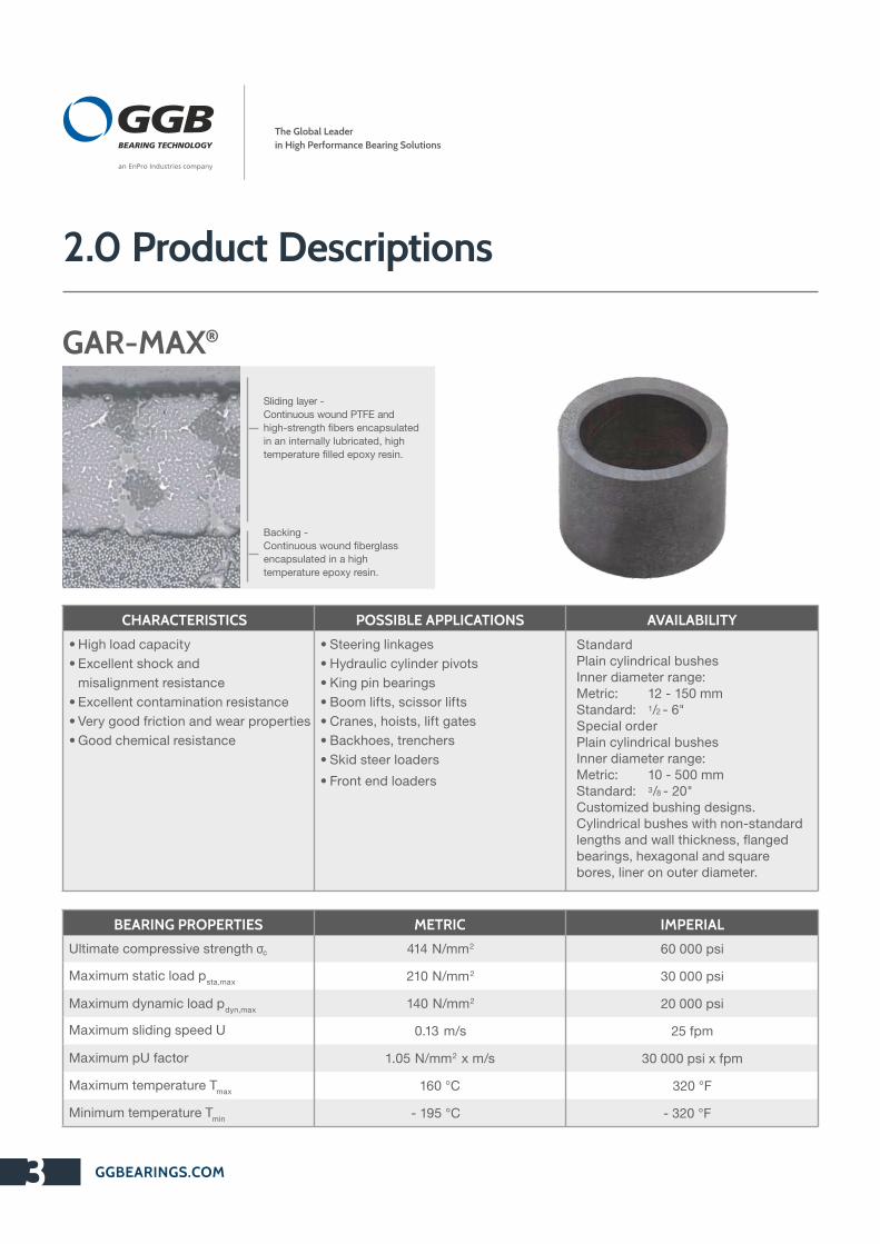
Sliding layer -
Continuous wound PTFE and
high-strength fibers encapsulated
in an internally lubricated, high
temperature filled epoxy resin.
Backing -
Continuous wound fiberglass
encapsulated in a high
temperature epoxy resin.
GAR-MAX®
CHARACTERISTICS POSSIBLE APPLICATIONS AVAILABILITY
• High load capacity
• Excellent shock and
misalignment resistance
• Excellent contamination resistance
• Very good friction and wear properties
• Good chemical resistance
• Steering linkages
• Hydraulic cylinder pivots
• King pin bearings
• Boom lifts, scissor lifts
• Cranes, hoists, lift gates
• Backhoes, trenchers
• Skid steer loaders
• Front end loaders
StandardPlain cylindrical bushes Inner diameter range:Metric: 12 - 150 mmStandard: 1/2 - 6"Special orderPlain cylindrical bushes Inner diameter range:Metric: 10 - 500 mmStandard: 3/8 - 20"Customized bushing designs.Cylindrical bushes with non-standard lengths and wall thickness, flanged bearings, hexagonal and square bores, liner on outer diameter.
BEARING PROPERTIES
Ultimate compressive strength
Maximum static load psta,max
Maximum dynamic load pdyn,max
Maximum sliding speed U
Maximum pU factor
Maximum temperature Tmax
Minimum temperature Tmin
METRIC
414 N/mm2
210 N/mm2
140 N/mm2
0.13 m/s
1.05 N/mm2 x m/s
160 °C
- 195 °C
IMPERIAL
60 000 psi
30 000 psi
20 000 psi
25 fpm
30 000 psi x fpm
320 °F
- 320 °F
GGBEARINGS.COM3
an EnPro Industries company
The Global Leader
in High Performance Bearing Solutions
σc

Sliding layer -
Proprietary filled PTFE tape liner,
0.38 mm (.015") standard thickness
(0.76mm (.030") available for
machining)
Backing -
Continuous wound fiberglass
encapsulated in a high
temperature epoxy resin.
GAR-FIL™
GGBEARINGS.COM 4
CHARACTERISTICS POSSIBLE APPLICATIONS AVAILABILITY
• High load capacity
• Good chemical resistance
• Machinable bearing surface
• High rotational speed capacity
• Very good friction and wear properties
• Excellent contamination resistance
• Valves
• Scissor lifts
• Pulleys
• Toggle linkages
StandardPlain cylindrical bushes Inner diameter range:Metric: 12 - 150 mmStandard: 1/2 - 6"Special orderPlain cylindrical bushes Inner diameter range:Metric: 10 - 500 mmStandard: 3/8 - 20"Customized bushing designs.Cylindrical bushes with non-standard lengths and wall thickness, flanged bearings, hexagonal and square bores, liner on outer diameter.
BEARING PROPERTIES
Ultimate compressive strength
Maximum static load psta,max
Maximum dynamic load pdyn,max
Maximum sliding speed U
Maximum pU factor
Maximum temperature Tmax
Minimum temperature Tmin
METRIC
379 N/mm2
140 N/mm2
140 N/mm2
2.50 m/s
1.23 N/mm2 x m/s
205 °C
- 195 °C
IMPERIAL
55 000 psi
20 000 psi
20 000 psi
500 fpm
35 000 psi x fpm
400 °F
- 320 °F
σc

Sliding layer -
Continuous wound PTFE and
high-strength fibers encapsulated
in an internally lubricated, high
temperature filled epoxy resin.
Backing -
Continuous wound fiberglass
encapsulated in a high
temperature epoxy resin.
GGBEARINGS.COM5
HSG™
CHARACTERISTICS POSSIBLE APPLICATIONS AVAILABILITY
• High static load capacity - twice as
high as standard GAR-MAX® bearings
• Excellent shock and misalignment
resistance
• Excellent contamination resistance
• Very good friction and wear properties
• Good chemical resistance
• Steering linkages
• Hydraulic cylinder pivots
• King pin bearings
• Boom lifts, scissor lifts
• Cranes, hoists, lift gates
• Backhoes, trenchers
• Skid steer loaders
• Front end loaders
StandardPlain cylindrical bushes Inner diameter range:Metric: 12 - 150 mmStandard: 1/2 - 6"Special orderPlain cylindrical bushes Inner diameter range:Metric: 10 - 500 mmStandard: 3/8 - 20"Customized bushing designs.Cylindrical bushes with non-standard lengths and wall thickness, flanged bearings, hexagonal and square bores, liner on outer diameter.
BEARING PROPERTIES
Ultimate compressive strength σc
Maximum static load psta,max
Maximum dynamic load pdyn,max
Maximum sliding speed U
Maximum pU factor
Maximum temperature Tmax
Minimum temperature Tmin
SI UNIT VALUE
621 N/mm2
415 N/mm2
140 N/mm2
0.13 m/s
1.05 N/mm2 x m/s
160 °C
- 195 °C
ANSI UNIT VALUE
90 000 psi
60 000 psi
20 000 psi
25 fpm
30 000 psi x fpm
320 °F
- 320 °F
an EnPro Industries company
The Global Leader
in High Performance Bearing Solutions

Sliding layer -
Continuous wound PTFE and high-
strength fibers encapsulated in high
temperature epoxy resin.
Backing -
Continuous wound fiberglass
encapsulated in a high
temperature epoxy resin.
GGBEARINGS.COM 6
MLG™
CHARACTERISTICS POSSIBLE APPLICATIONS AVAILABILITY
• Value engineered ilament wound
bearing for lighter duty applications
• High load capacity
• Good misalignment resistance
• Excellent shock resistance
• Good friction and wear properties
• Good chemical resistance
• Construction and earth moving
equipment
• Conveyors
• Cranes and hoists
• Hydraulic cylinder pivots
StandardPlain cylindrical bushes Inner diameter range:Metric: 12 - 150mmStandard: 1/2 - 6"Special orderPlain cylindrical bushes Inner diameter range:Metric: 10 - 500 mmStandard: 3/8 - 20"Customized bushing designs.Cylindrical bushes with non-standard lengths and wall thickness, flanged bearings, hexagonal and square bores, liner on outer diameter.
BEARING PROPERTIES
Ultimate compressive strength
Maximum static load psta,max
Maximum dynamic load pdyn,max
Maximum sliding speed Ulim
Maximum pU factor
Maximum temperature Tmax
Minimum temperature Tmin
METRIC
414 N/mm2
210 N/mm2
140 N/mm2
0.13 m/s
1.05 N/mm2 x m/s
160 °C
- 195 °C
IMPERIAL
60 000 psi
30 000 psi
20 000 psi
25 fpm
30 000 psi x fpm
320 °F
- 320 °F
σc

GGBEARINGS.COM7
HPM™
Sliding layer -
Continuous wound PTFE and
high-strength fibers encapsulated
in a internally-lubricating, high
temperature filled epoxy resin.
Backing -
Continuous wound fiberglass
encapsulated in a high
temperature epoxy resin.
POSSIBLE APPLICATIONS AVAILABILITY
• Designed for hydropower applications
• High load capacity
• Excellent shock and edge loading capacity
• Low friction, superior wear rate and bearing life
• Excellent corrosion resistance
• Dimensional stability - very low water absorption, low swelling
• Environmentally friendly
• Servo-motor bearings
• Linkage bearings
• Wicket gate bearings
• Guide vane bearings
• Intake gate sliding segments
• Spillway gate bearings
• Trash rake bearings
• Fish screen bearings
• Trunnion bearings
• Blade bearings
• Injector bearings
• Delector bearings
• Ball and butterfly trunnion bearings
Standard
Plain cylindrical bushings
Special order
Cylindrical bushes from
10 mm to 500 mm (20"),
customized bearing designs
BEARING PROPERTIES
Ultimate compressive strength
Maximum static load psta,max
Maximum dynamic load pdyn,max
Maximum sliding speed U
Maximum pU factor
Maximum temperature Tmax
Minimum temperature Tmin
METRIC
345 N/mm2
210 N/mm2
140 N/mm2
0.13 m/s
1.23 N/mm2 x m/s
160 °C
- 195 °C
IMPERIAL
50 000 psi
30 000 psi
20 000 psi
25 fpm
35 000 psi x fpm
320 °F
- 320 °F
CHARACTERISTICS
an EnPro Industries company
The Global Leader
in High Performance Bearing Solutions
σc

GGBEARINGS.COM 8
Sliding layer -
Machinable continuous wound
PTFE and high-strength fibers
encapsulated in an internally
lubricated, high temperature filled
epoxy resin.
Backing -
Continuous wound fiberglass
encapsulated in a high
temperature epoxy resin.
HPMB™ Machinable Bearing Material
CHARACTERISTICS POSSIBLE APPLICATIONS AVAILABILITY
• Machinable inner and outer diameters for superior application precision, circularity and cylindricity tolerances
• Pre-machined high precision HPMB bearings available for i mmediate installation
• High precision through easy single point machining of the bearing liner, on-site prior to installation
• Superior precision achieved with post-installation (inner diameter tolerance IT7 attainable) single point machining of the bearing liner
• High load capacity and excellent dithering performance
• Excellent shock and edge loading capacity
• Low friction with negligible stick-slip
• Low wear rate for extended bearing life
• Excellent corrosion resistance
• Dimensionally stable - very low water absorption, low swelling
• Environmentally friendly grease-free operation
• Steering linkages
• Hydraulic cylinder pivots
• King pin bearings
• Boom lifts, scissor lifts
• Cranes, hoists, lift gates
• Backhoes, trenchers
• Skid steer loaders
• Front end loaders
• Injection molding machines
• Railway applications
• Water turbines
• Valves
Special order
Finished cylindrical bushings,
pre-machined cylindrical
bushings, flanged cylindrical
bushings (subject to design
review)
BEARING PROPERTIES
Ultimate compressive strength σc
Maximum static load psta,max
Maximum dynamic load pdyn,max
Maximum sliding speed U
Maximum pU factor
Maximum temperature Tmax
Minimum temperature Tmin
METRIC
414 N/mm2
210 N/mm2
140 N/mm2
0.13 m/s
1.23 N/mm2 x m/s
160 °C
- 195 °C
IMPERIAL
60 000 psi
30 000 psi
20 000 psi
25 fpm
35 000 psi x fpm
320 °F
- 320 °F
NEW IN 2015

GGBEARINGS.COM9
Sliding layer -
Proprietary filled PTFE tape liner.
Backing -
Flat material continuous woven
cloth laminate impregnated and
cured with epoxy resin.
HPF™
BEARING PROPERTIES METRIC IMPERIAL
Ultimate compressive strength σc
379 N/mm2 55 000 psi
Maximum static load psta,max
140 N/mm2 20 000 psi
Maximum dynamic load pdyn,max
140 N/mm2 20 000 psi
Maximum sliding speed U 2.5 m/s 500 fpm
Maximum pU factor 1.23 N/mm2 x m/s 35 000 psi x fpm
Maximum temperature Tmax 140 °C 285 °F
Minimum temperature T - 195 °C - 320 °F
CHARACTERISTICS POSSIBLE APPLICATIONS AVAILABILITY
• Designed for hydropower applications
• Machinable bearing surface
• High load capacity
• Low friction, superior wear rate and bearing life
• Excellent corrosion resistance
• Dimensional stability - very low water absorption,
low swelling
• Environmentally friendly
• Servo-motor bearings
• Operating ring sliding segments
• Linkage bearings
• Wicket gate bearings
• Guide vane bearings
• Intake gate sliding segments
• Spillway gate bearings
• Trash rake bearings
• Fish screen bearings
• Trunnion bearings
• Blade bearings
• Injector bearings
• Delector bearings
• Ball and butterfly trunnion
bearings
Special order
Cylindrical bearings, diameters
up to 500 mm (20"); thrust
bearings and sliding plates
an EnPro Industries company
The Global Leader
in High Performance Bearing Solutions
min

GGBEARINGS.COM 10
MEGALIFE XT Thrust Washers
Sliding layer -
Proprietary filled PTFE tape liner on
both sides.
Core -
Continuously woven layer of
filament fiberglass encapsulated
in a high temperature epoxy resin.
CHARACTERISTICS POSSIBLE APPLICATIONS AVAILABILITY
• Excellent shock resistance
• High load capacity
• Excellent misalignment resistance
• Excellent contamination resistance
• Good surface speed capability
• Very good friction and wear properties
• Good chemical resistance
• Pulley spacers
• Gear spacers
• Aerial lifts
• Fork lift masts
• King pins
• Steering links
• Lift gates
• Cranes
• Backhoes
• Valve actuator linkages
Standard
Thrust washers, standard sizes
see pages 49-50
Special order
Thrust washers with non-standard
dimensions, customized bearing
designs
BEARING PROPERTIES
Ultimate compressive strength
Maximum static load psta,max
Maximum dynamic load pdyn,max
Maximum sliding speed U
Maximum pU factor
Maximum temperature Tmax
Minimum temperature Tmin
METRIC
207 N/mm2
140 N/mm2
140 N/mm2
0.50 m/s
1.23 N/mm2 x m/s
175 °C
- 195 °C
IMPERIAL
30 000 psi
20 000 psi
20 000 psi
100 fpm
35 000 psi x fpm
350 °F
- 320 °F
σc

GGBEARINGS.COM11
Multifil™
CHARACTERISTICS POSSIBLE APPLICATIONS AVAILABILITY
• Superior sliding bearing material
which can be easily bonded to any
clean, rigid substrate
• Reduces vibration
• Machined tool ways
• Sliding applications where bearing
tape can be added on
Standard
Sliding plates, tape with 0.38 mm
(0.015") to 3.2 mm (0.125") thickness
and 305 mm (12") or 610 mm (24") width
Structure -
PTFE tape with proprietary
filler system
BEARING PROPERTIES
Maximum static load psta,max
Maximum dynamic load pdyn,max
Maximum sliding speed U
Maximum pU factor
Maximum temperature Tmax
Minimum temperature Tmin
METRIC
70 N/mm2
35 N/mm 2
2.5 m/s
0.32 N/mm 2 x m/s
280 °C
- 200 °C
IMPERIAL
10 000 psi
5 000 psi
500 fpm
9 000 psi x fpm
540 °F
- 330 °F
an EnPro Industries company
The Global Leader
in High Performance Bearing Solutions

GGBEARINGS.COM 12
BEARING PROPERTIES
Load Carrying Capability
Shock Loading Resistance
SpeedCapability
Contamination Resistance
Misalignment Resistance
Machinability
®GAR-MAX 1 2 3 1 2 4
TMGAR-FIL 1 3 1 2 4 1
TMHSG 1 1 3 1 1 4
TMMLG 1 2 3 2 3 4
TMHPM 1 2 3 1 2 4
®HPMB 1 2 3 1 2 1
TMHPF , Sliding Plate 1 3 1 2 4 1
TMHPF , 1 3 1 2 4 1
MEGALIFE XT 2 3 2 2 3 2
TMMultifil 3 3 1 2 2 1
RANKING
1 Excellent
2 Good
3 Fair
4 Not Recommended
2.1 Performance Comparison Chart
Table 1: Performance comparison chart
CylindricalBearing
GGBEARINGS.COM13
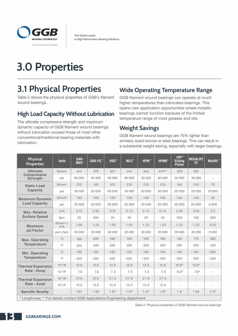
3.0 Properties
Table 2 shows the physical properties of GGB´s filament
wound bearings.
3.1 Physical Properties
High Load Capacity Without Lubrication
Wide Operating Temperature Range
Weight SavingsThe ultimate compressive strength and maximum
dynamic capacity of GGB filament wound bearings
without lubrication exceed those of most other
conventional/traditional bearing materials with
lubrication.
GGB filament wound bearings can operate at much
higher temperatures than lubricated bearings. This
opens new application opportunities where metallic
bearings cannot function because of the limited
temperature range of most greases and oils.
GGB filament wound bearings are 75% lighter than
similarly sized bronze or steel bearings. This can result in
a substantial weight saving, especially with larger bearings.
Table 2: Physical properties of GGB filament wound bearings
Physical Properties
Units GAR-MAX®
®GAR-FIL HSG™™ MLG™ HPM™ HPMBHPF™
Sliding Plates
MEGALIFE XT Multifil ™
Ultimate Compressive
Strength
N/mm2 414 379 621 414 345 414** 379 207 -
psi 60 000 55 000 90 000 60 000 50 000 60 000 55 000 30 000 -
Static Load Capacity
N/mm2 210 140 415 210 210 210 140 140 70
psi 30 000 20 000 60 000 30 000 20 000 30 000 20 000 20 000 10 000
Maximum Dynamic Load Capacity
N/mm2 140 140 140 140 140 140 140 140 35
psi 20 000 20 000 20 000 20 000 20 000 20 000 20 000 20 000 5,000
Max. Relative Surface Speed
m/s 0.13 2.50 0.13 0.13 0.13 0.13 2.50 0.50 2.5
fpm 25 500 25 25 25 25 500 100 500
MaximumpU Factor
N/mm2 x m/s
1.05 1.23 1.05 1.05 1.23 1.23 1.23 1.23 0.32
psi x fpm 30 000 35 000 30 000 30 000 35 000 35 000 35 000 35 000 9 000
Max. Operating Temperature
°C 160 205 160 160 160 160 140 175 280
°F 320 400 320 320 320 320 285 350 540
Min. Operating Temperature
°C - 195 - 195 - 195 - 195 - 195 - 195 - 195 - 195 - 200
°F - 320 - 320 - 320 - 320 - 320 - 320 - 320 - 320 - 330
Thermal ExpansionRate - Hoop
10-6/K 12.6 12.6 12.6 12.6 12.6 12.6 10.8* 12.6* -
10-6/F 7.0 7.0 7.0 7.0 7.0 7.0 6.0* 7.0* -
Thermal ExpansionRate - Axial
10-6/K 27.0 27.0 27.0 27.0 27.0 27.0 - - -
10-6/F 15.0 15.0 15.0 15.0 15.0 15.0 - - -
Specific Gravity - 1.87 1.96 1.87 1.87 1.87 1.87 1.9 1.85 2.37
* Lengthwise; ** For details contact GGB Applications Engineering department
an EnPro Industries company
The Global Leader
in High Performance Bearing Solutions

Table 3 presents the properties information in a convenient table to help you choose the best product for your application.
3.2 Performance Comparison
NoteActual performance depends on the interaction of many parameters that may vary with the specific application.
For example, maximum values listed for loads, speeds, and temperature cannot be used simultaneously.
However, in certain applications, individual values can be exceeded. For conditions that do exceed the
recommended design limits, contact our Engineering Department.
Material
Max. Dynamic Capacity(<0.025 m/s (5 sft/min))
Maximum TemperatureThermal Expansion
Rate - Hoop SpecificGravity
N/mm2 psi °C °F -610 /K -610 /°F
Cast Bronze* 41 6 000 71 160 18.0 10 8.80
Porous Bronze** 28 4 000 71 160 18.0 10 7.50
Alloyed Bronze* 69 10 000 93 200 28.8 16 8.10
Steel-Backed Bronze* 24 3 500 93 200 14.4 8 8.00
Hardened Steel* 276 40 000 93 200 12.6 7 7.90
Zinc Aluminum* 38 5 500 93 200 27.0 15 5.00
Fabric-Reinforced Phenolic*
41 6 000 93 200 36.0 20 1.60
Reinforced PTFE 14 2 000 260 500 99.0 55 2.00
140 20 000 160 320 12.6 7 1.87
140 20 000 205 400 12.6 7 1.96
140 20 000 160 320 12.6 7 1.87
140 20 000 160 325 12.6 7 1.87
140 20 000 160 320 12.6 7 1.87
140 20 000 160 325 12.6 7 1.87
140 20 000 140 285 10.8*** 6.0*** 1.90
140 20 000 175 350 12.6*** 7.0*** 1.85
35 5 000 280 540 - - 2.37
* With lubrication; ** Oil impregnated; *** Lengthwise
Table 3: Comparison of various bearing materials
GGBEARINGS.COM 14
®GAR-MAX
TMGAR-FIL
TMHSG
TMMLG
TMHPM
®HPMB
TMHPF , Sliding Plate
MEGALIFE XT
TMMultifil

GGBEARINGS.COM15
GGB’s filament wound bearings are resistant to a
wide variety of chemicals including acids, bases, salt
solutions, oils, fuels, alcohols, solvents and gases.
GGB’s filament wound bearings offer greater chemical
resistance than metallic bearings. In particular,
GAR-FIL is resistant to the greatest number of
chemicals, and is used in a wide range of valves
employed in the chemical processing industry as
well as for fire-safe valves.
The chemical resistance of GGB’s filament wound
bearings to many common chemicals at 70 °F is shown
in Table 4.
We recommend conducting a chemical resistance test
prior to specifying a bearing that will be exposed to a
chemical. An effective test (ASTM D 543) is to submerge
a sample bearing in the subject chemical at the
maximum anticipated operating temperature for seven
days. If there is a change in the weight, dimensions, or
compressive strength of the bearing, then the bearing is
not resistant to the chemical.
3.3 Chemical Resistance
GAR-MAX® HSG™GAR-FIL™ MLG™ ®HPM™/ HPMB HPF™ / MEGALIFE XT Multifil™
Acids 10%
Acetic Yes Yes Yes Yes Yes Yes No
Arsenic No Yes No No No Yes Yes
Boric Yes Yes Yes Yes Yes Yes Yes
Carbonic No No No No No No No
Citric Yes Yes Yes Yes Yes Yes Yes
Hydrochloric Yes Yes Yes Yes Yes Yes No
Hydro-fluoric No No No No No No No
Nitric No No No No No No No
Sulfuric Yes Yes Yes Yes Yes Yes Yes
Bases 10%
Aluminum Hydroxide Yes Yes Yes Yes Yes Yes Yes
Calcium Hydroxide Yes Yes Yes Yes Yes Yes Yes
Magnesium Hydroxide Yes Yes Yes Yes Yes Yes Yes
Potassium Hydroxide Yes Yes Yes Yes Yes Yes Yes
Sodium Hydroxide Yes Yes Yes Yes Yes Yes Yes
Salts
Aluminum Chloride Yes Yes Yes Yes Yes Yes Yes
Aluminum Nitrate Yes Yes Yes Yes Yes Yes Yes
Aluminum Sulfate Yes Yes Yes Yes Yes Yes Yes
Calcium Chloride Yes Yes Yes Yes Yes Yes Yes
Ferric Chloride Yes Yes Yes Yes Yes Yes Yes
Magnesium Carbonate Yes Yes Yes Yes Yes Yes Yes
Magnesium Chloride Yes Yes Yes Yes Yes Yes Yes
Magnesium Sulfate Yes Yes Yes Yes Yes Yes Yes
Sodium Acetate Yes Yes Yes Yes Yes Yes Yes
Sodium Bicarbonate Yes Yes Yes Yes Yes Yes Yes
Sodium Bisulfate Yes Yes Yes Yes Yes Yes Yes
Sodium Chloride Yes Yes Yes Yes Yes Yes Yes
Sodium Nitrate Yes Yes Yes Yes Yes Yes Yes
Zinc Sulfate Yes Yes Yes Yes Yes Yes Yes
Alcohols
Acetol Yes Yes Yes Yes Yes Yes Yes
an EnPro Industries company
The Global Leader
in High Performance Bearing Solutions

GGBEARINGS.COM 16
Allyl No No No No No No NoAmyI Yes Yes Yes Yes Yes Yes YesButyl No No No No No No NoEthyl Yes Yes Yes Yes Yes Yes YesIso Butyl Yes Yes Yes Yes Yes Yes YesIso PropyI Yes Yes Yes Yes Yes Yes YesMethyl Yes Yes Yes Yes Yes Yes Yes
Yes Yes Yes Yes Yes Yes Yes
Acetone Yes Yes Yes Yes Yes Yes YesBenzene No No No No No No NoCarbon Tetrachloride Yes Yes Yes Yes Yes Yes YesMethylene Chloride No No No No No No NoMethyl Ethyl Ketone Yes Yes Yes Yes Yes Yes YesNaphtha Yes Yes Yes Yes Yes Yes YesToluol Yes Yes Yes Yes Yes Yes YesTrichlorethane No Yes No No No Yes Yes
Cottonseed Yes Yes Yes Yes Yes Yes YesCrude Oil Yes Yes Yes Yes Yes Yes YesHydraulic Fluids Yes Yes Yes Yes Yes Yes YesLinseed Oil Yes Yes Yes Yes Yes Yes YesMotor Oil Yes Yes Yes Yes Yes Yes YesTransmission Fluids Yes Yes Yes Yes Yes Yes Yes
Diesel Yes Yes Yes Yes Yes Yes YesGasoline Yes Yes Yes Yes Yes Yes YesJet Fuel Yes Yes Yes Yes Yes Yes YesKerosene Yes Yes Yes Yes Yes Yes YesGases Yes Yes Yes Yes Yes Yes YesAcetylene Bromine No No No No No No NoButane Yes Yes Yes Yes Yes Yes YesCarbon Dioxide Yes Yes Yes Yes Yes Yes YesChlorine No Yes No No No Yes YesEthers Yes Yes Yes Yes Yes Yes YesFluorine No No No No No No NoHydrogen Yes Yes Yes Yes Yes Yes YesNatural Gas Yes Yes Yes Yes Yes Yes YesNitrogen Yes Yes Yes Yes Yes Yes YesOzone Yes Yes Yes Yes Yes Yes YesPropane Yes Yes Yes Yes Yes Yes YesSulfur Dioxide Yes Yes Yes Yes Yes Yes Yes
Anhydrous Ammonia No No No No No No NoDetergents Yes Yes Yes Yes Yes Yes YesEthylene Glycol Yes Yes Yes Yes Yes Yes YesFormaldehyde Yes Yes Yes Yes Yes Yes YesFreon Yes Yes Yes Yes Yes Yes YesHydrogen Peroxide No No No No No No NoLime Yes Yes Yes Yes Yes Yes YesWater Yes Yes Yes Yes Yes Yes YesSea water Yes Yes Yes Yes Yes Yes Yes
Table 4: Chemical Resistance
GAR-MAX® HSG™GAR-FIL™ MLG™ ®HPM™/ HPMB HPF™ / MEGALIFE XT Multifil™
PropyISolvents
Oils
Miscellaneous
Fuels

GGBEARINGS.COM17
In the high load applications anticipated for filament wound bearings, radial displacement will result from a
combination of many variables. These include adhesive wear, abrasion, deformation due to misalignment of
the shaft, high interface temperatures, ingress of dirt, fluid contamination and mating surface conditions. With 2 ® ™design pressures of less than 69 N/mm [10,000 psi], millions of cycles can be achieved with GAR-MAX , HSG ,
®™ ™ ™GAR-FIL , HPMB , HPM and HPF bearings.
Fig. 3 and Fig. 4 show the
rate of wear measured in
continuous cycle testing for ® ®a GAR-MAX , HPMB
™and GAR-FIL bearings.
4.0 Data for Designers
4.1 Wear Rate
Fig. 3: Wear rate for GAR-MAX® ® and HPMB
TMFig. 4: Wear rate for GAR-FIL
0.00
0.05
0.10
0.15
0.20
0.25
0
100.
000
200.
000
300.
000
400.
000
500.
000
Cycles
Wear,
mm
Wear,
inch
® ®GAR-MAX and HPMB
®GAR-MAX
ID: 25.40 mm [1.000 inch]Length: 19.05 mm [0.750 inch]Shaft: 1045 Steel, 58-63 RcFinish R : 0.4µm [16 µinch]aP = 2 69 N/mm [10,000 psi]Oscillation rate:15 cpm at ±30°V = 0.007 m/s [1.3 ft/min]PV = 2N/mm ·m/s [19,500 psi·fpm]
0.00
0.05
0.10
0.15
0.20
0.25
0
100,
000
200,
000
300,
000
400,
000
500,
000
0.000
0.001
0.002
0.003
0.004
0.005
0.006
0.007
0.008
0.009
0.010
0.000
0.001
0.002
0.003
0.004
0.005
0.006
0.007
0.008
0.009
0.010
Cycles
Wear,
mm
Wear,
inch®GAR-FIL WEAR
Bearing:GF1620-012ID:25.40mm[1.000inch]Length:19.05mm[0.750inch]Shaft:1045Steel,58-63RcFinishR :0.4µm[16µinch]aP = 103 MPa[15,000psi]Oscillationrate:15cpmat±30°V = 0.007 m/s[1.3ft/min]PV = 0.68 2N/mm ·m/s[19,500psi·fpm]
®HPMB
0.68
0.00
0.05
0.10
0.15
0.20
0.25
0
100,
000
200,
000
300,
000
400,
000
500,
000
0.000
0.001
0.002
0.003
0.004
0.005
0.006
0.007
0.008
0.009
0.010
Cycles
Wear,
mm
Wear,
inchTM GAR-FIL WEAR
Bearing:GF1620-012ID:25.40mm[1.000inch]Length:19.05mm[0.750inch]Shaft:1045Steel,58-63RcFinishR :0.4µm[16µinch]aP = 103 MPa[15,000psi]Oscillationrate:15cpmat±30°V = 0.007 m/s[1.3ft/min]PV = 0.68 2N/mm ·m/s[19,500psi·fpm]
an EnPro Industries company
The Global Leader
in High Performance Bearing Solutions

GGBEARINGS.COM 18
The prime factors affecting the friction of filament wound bearings are pressure, speed, temperature and mating
surface conditions. Generally, the pressure is the most influential.
Fig. 5 shows how friction changes at various pressures. This information can be used to estimate the torque
required to initiate motion in GGB ilament wound bearings:
With frequent starts and stops,
the static coefficient of friction is
approximately equal to or slightly
less than the dynamic coefficient of
friction as measured in laboratory
testing. After progressively longer
periods of sitting idle or dwell under
load (e.g., of hours or days), the
static coefficient of friction of the
first movement has been measured
to be up to 200% higher, particularly
before bedding-in. This phenomenon
must be considered when designing
long dwell period applications.
Extremely low torque applications
should be monitored or specifically
tested for friction when prime mover
torque requirements must be
determined.
4.2 Frictional Properties
Fig. 5: Coefficient of friction vs specific load
or
Torqu eμ F Di⋅⋅2000
------------------
(4.2.1)
=
[N·m]
Torqu e2
------------------
(4.2.2)
=
[lbs·in]
WHERE
µ Coefficient of friction
F Applied load, [Newtons] or [pounds]
DI Bearing nominal ID, [mm] or [inches]
0.02
0.03
0.04
0.05
0.06
0.07
0.08
0.09
0.10
0.11
0.12
30 40 50 60 70 80 90 100 110
5,000 6,000 7,000 8,000 9,000 10,000 11,000 12,000 13,000 14,000 15,000
MLGTM
GAR-MAX®
GAR-FIL®HPMB
TM
Test Conditions:ID: 25.4 mm [1.00 inch]OD: 31.75 mm [1.25 inch]Length: 19.05 mm [0.75 inch]Shaft: 1040 Steel, 58-63 RcFinish R : 0.13 µm [5 µinch]aOscillation rate: 15 cpm at ±30°V = 0.007 m/s [1.3 ft/min]Break-in for 24 hours at 103 MPa[15,000 psi] prior to measuring friction
Specific Load [MPa]
Coeffi
cient of fr
ictio
n μ
Specific Load [psi]
μ F Di⋅⋅

GGBEARINGS.COM19
Operating temperature is an important consideration
when specifying bearing products since temperature
will have a direct effect on bearing load capacity and
wear resistance. GGB filament wound bearings consist
of a rugged outer shell of filament wound fiberglass
encapsulated in high temperature epoxy.
This combination of materials enables GGB filament
wound bearings to operate at higher temperatures
than most other conventional plain bearings as
indicated in Table 3.
At elevated temperatures GGB filament wound bearings
have reduced load carrying capabilities due to the
softening of the self-lubricating surfaces.
® ®™ ™However, GAR-MAX , MLG , HPMB , and HPM are
not influenced by temperature to the same degree ™ ™ ™ as GAR-FIL and HPF . GAR-FIL bearings have been
used in low temperature (cryogenic) applications.
The maximum unit load which can be supported by
filament wound bearings will depend upon the type of
load. It will be highest under steady loads, whereas,
dynamic loads or oscillating motion, which produce
fatigue stresses in the bearing, will result in a reduction
of load capacity.
The maximum unit loads specified in Table 2 assume
good alignment between the bearing and mating
surface and running clearances listed in the standard
product tables on pages 39 through 48.
The maximum static and dynamic loads given in
Table 2 are based on bearings having a wall thickness
of 2.5 mm [0.100 inch] or greater. Thin-walled bearings,
those with a wall thickness between 1.5 mm
[0.060 inch] and 2.5 mm [0.100 inch] have a reduced
load capacity because of the reduced number of
filament wound fiberglass crossovers that constitute
the backing material. Wall thicknesses greater than
6.35 mm [0.250 inch] do not increase load capacity.
® ®Many applications for GAR-MAX , HBMB , and ™ HSG bearings involve applied loads plus the
presence of shock and impulse loading along with
additional loads due to structural bending. As an
example, hydraulic cylinder pivots or clevis joints
used in front end loaders, graders, and other types
of off-highway vehicles require the consideration of
misalignment and G-impact force. Experience gained ® ™in the application of GAR-MAX and HSG bearings
on this type of equipment has led us to recommend
the maximum specific load (pressures) shown in
Table 5. Greater specific loads have shown surface
distress in operation since the cumulative influence
of misalignment and shock will increase the actual
specific load.
The bearing length can also influence the distribution
of load along the length of the bearing. A bearing that
is heavily loaded and having a relatively long length
will, due to shaft deflection, have disproportionately
high unit loading at each end. For this reason, we do
not recommend length-to-diameter ratios that are
greater than 2.0. Conversely, very short bearings,
those with length-to-diameter ratios less than 0.25
are not recommended because of potential bearing
retention problems.
4.3 Operating Temperature
4.4 Load Capacity
an EnPro Industries company
The Global Leader
in High Performance Bearing Solutions

GGBEARINGS.COM 20
GGB´s filament wound bearings can operate over a
wide range of operating velocities as shown in Table 2.
™ ™GAR-FIL and HPF bearings can operate without
lubrication at speeds up to 2.5 m/s [500 fpm] with a
maximum pU value to 0.3 N/mm2 x m/s [9,000 psi x fpm].
This performance capability is due to the proprietary
filled-PTFE liner.
Since surface velocity influences the amount of heat
generated in a plain bearing, additional clearance may be ™required at higher operating speeds. With GAR-FIL a nd
™HPF bearings, when operating over 0.25 m/s [50 fpm],
additional clearances are required to accommodate for
thermal expansion due to the heat generated.
® ®™ ™ ™GAR-MAX , HSG , MLG , HPMB and HPM bearings,
which have a maximum speed limit of 0.13 m/s [25 fpm],
are more suitable for high-load and low-speed applications. ® ®™ ™ ™Since most GAR-MAX , HSG , MLG , HPMB and HPM
bearings are designed to operate at less than 0.05 m/s
[10 fpm], additional clearances are normally not required.
MEGALIFE XT thrust bearings are limited to 0.50 m/s
[100 fpm].
™Multifil bearing tape can operate with speed up to 2.5 m/s
[500 fpm].
The pU factor, which is the product of specific load
(pressure) times surface velocity, is used as a guide
in determining the useful life of plain bearings and is
also an indication of heat generated within the bearing
contact zone. The maximum pU factors listed in
Table 2 are based on high-load and low-speed
applications. The calculated unit load p, relative surface
velocity U and operating temperature must be used
along with the pU factor when selecting a bearing
product for a given application. These values are then
compared against published maximum recommended
values for load, speed, temperature and pU for the
bearing product. For an application to be successful,
each of the application values must not exceed the
published maximum recommended values. To complete
the bearing analysis, bearing life should be estimated
using the method given in section 5.5
4.5 Surface Speed
4.6 pU Factor
ApplicationDesign Specific Load*
Impact [G]N/mm2 psi
Dozer Yoke 34 5,000 3
Excavators 34 5,000 3
Back Hoes 34 5,000 3
Loader Linkages 34 5,000 3
Rollers 48 7,000 2
Bogie Wheel Pivots 48 7,000 2
Track Frame Pivots 48 7,000 2
Steer Cylinders 69 10,000 1
Control Linkage 69 10,000 1
Dump/Swing Cylinders 69 10,000 1
* Includes hydraulic check valve pressure but does not include impact, misalignment or vehicle driving force
Table 5: Specific application impact loading factors

GGBEARINGS.COM21
Proper running clearance is a critical factor in bearing
performance. In low speed oscillating pivot applications,
the minimum possible recommended clearance can be
as small as 0.013 mm [0.0005 inch] for flament wound
bearings. The shaft or pin will fit nearly line-to-line during
the assembly process. However, since little or no heat
is generated during very slow oscillating operation,
additional clearance is not required.
For more dynamic applications involving continuous
rotation at higher speeds or elevated ambient
temperatures, minimum clearances may be as high as
0.005 mm/mm [0.005 inch/inch] of diameter.
GAR-MAX ,® HSG ,™ MLG ,™
™
and HPM™ bearings cannot be
sized or machined on their ID due to the liner composition.
However, HPMB , GAR-FIL® and HPF™ bearings can be
sized or machined for close tolerance control.
HPMB bearings can be machined on the inner
diameter to the depth up to 1 mm [0.040 inch] on
diameter in standard configuration, and to the depth
up to 3 mm [0.118 inch] on diameter upon request.
Standard GAR-FIL and HPF™™ bearings are supplied
with a 0.38 mm [0.015 inch] thick proprietary filled-PTFE
tape liner that can be bored at assembly if necessary.
GAR-FIL
®
and HPF™™ bearings can also be furnished with
a thicker liner that allows for a greater depth for boring.
For further information, contact GGB.
Wall Thickness
Bearings with wall thicknesses less than 2.5 mm
[0.100 inch] should be avoided since thin-walled
bearings have reduced load capacity, approximately
50% less than our rated load capacity for GGB filament
wound bearings.
The minimum recommended wall thickness is 1.5 mm
[0.060 inch]. Wall thicknesses greater than 6.35 mm
[0.250 inch] do not increase load capacity.
Clearance
As noted previously, the minimum running clearance
applies only to low speed applications operating at
ambient temperatures.
For GAR-FIL and HPF™™ bearings operating at surface
speeds greater than 0.25 m/s [50 fpm] or at elevated
temperatures, additional clearance may be required.
Bearing Length
In designing bearings, the shaft diameter is usually
determined by the need for physical stability or
stiffness; therefore, only the bearing length must
be determined based upon operating pressure and
required life.
A short bearing should be limited to a length-to-
diameter ratio of 0.25 as a minimum to insure sufficient
retention in the housing.
A long bearing is not recommended because of
potential shaft deflection and misalignment problems
as described in Section 6.0. A long heavily loaded
bearing will have disproportionately high specific
loading at each end due to shaft deflection. For this
reason, we do not recommend length-to-diameter
ratios greater than 2.0.
4.7 Operating Clearances
4.8 Dimensional ConsiderationsBefore designing a special GGB filament wound bearing, there are several important considerations to keep in mind:
an EnPro Industries company
The Global Leader
in High Performance Bearing Solutions
GGBEARINGS.COM 22
Being part of the complete assembly, an appropriate
design of the shaft is of the most utmost importance
to obtaining the correct operating performance of
the bearing. Most steel alloys are acceptable as
shaft materials. Hardened steel shafts offer better
performance in high load applications or in the
presence of abrasive contaminants by providing
greater protection for the mating surface.
When bearing operating pressures exceed a value of
about 14 N/mm2 [2,000 psi], minimum shaft hardness
should be at least Brinnel 480 HB [Rockwell C50].
Fully hardened shafts are usually not necessary.
GGB filament wound bearings offer good
embeddibility in the presence of contaminants;
however, we strongly recommend the use of seals.
Hardened stainless steel or hard chrome plating is
recommended when corrosion resistance is required.
Equally important as material selection is shaft
surface finish. A surface finish between 0.15 to
0.40 µm [6 to 16 µinches] will insure the most
effective bearing performance by assuring maximum
bearing wear resistance and lowest coefficient of
friction. Rougher surface finishes can be used but
there will be a reduction in bearing life. This is due to
the rough shaft abrading the relatively soft polymer
liner of the bearings.
We recommend that the ends of the shaft have
chamfers or rounded edges to facilitate assembly and
minimize the chance of scoring the bearing.
The running clearances given in section 8 for standard
GGB filament wound bearings are based upon
installation in rigid steel or cast iron housings at normal
ambient temperature. If the housing is made from non-
ferrous alloys, such as aluminum, and will be subjected
to elevated operating temperatures, there will be a
potential for reduced bearing retention due to the
thermal expansion of the housing.
In applications where non-ferrous alloy housings are
to be used at elevated temperatures, the interference
between the bearing and housing bore may have
to be increased to assure adequate retention of the
bearing in the housing. To prevent shaft interference at
assembly, the shaft diameter must be equally reduced to
compensate for the additional interference it. For further
information contact GGB.
GGB filament wound bearings are recommended to be
used dry. However, grease can be used to protect and/or
to purge the bearing zone of corrosion or contaminants.
In applications where high cyclic vibrations are present,
hydrostatic erosion of liner fibers by the grease may
occur over long periods of time. This should be
monitored to assure liner integrity over the operating life
of the equipment.
GAR-FIL and HPF™™ bearings can be used when
submerged in oil or other lubricating liquids. Liquidous
lubricants will reduce the coefficient of friction and
bearing wear. However, the lubricant must be constantly
maintained and kept free of abrasive contaminants.
Grease is not recommended for GAR-FIL and
HPF™
™
bearings.
HPMB , HPM™ and HPF™ bearings are specifically
designed for hydropower applications where they can be
used both dry and submerged in water. We recommend
that hardened stainless steel shafting, such as 440
stainless steel, be used to minimize the chance of shaft
corrosion.
MEGALIFE XT washers and sliding plates are typically
used dry but can also be used in greased applications.
Multifil™ bearing tape can be used dry or with lubricants.
Liquid lubricants and greases attract contaminating
particles that may migrate into the bearing. To minimize
bearing contamination, the use of seals or wipers is
highly recommended.
4.9 Shaft Material and Surface Finish
4.10 Housing Material
4.11 Lubrication®
GGBEARINGS.COM23
Multifil™ tape is a superior sliding bearing product developed specifically for machine tool ways, gibs, and other
sliding applications. This unique product is a blend of virgin PTFE and a combination of fillers which vastly
improve the bearing properties of the base resin.
This bearing tape is widely used by machine tool rebuilders and in-plant personnel to restore existing equipment
to like new precision, as well as by many leading machine tool manufacturers. The tape is easy to apply to any
clean rigid substrate, inexpensive and provides remarkable performance.
As a sliding bearing product, Multifil™ tape is unequalled for providing high compressive strength and load
carrying capabilities, low friction, precise positioning accuracy and minimal wear – with or without lubrication.
In addition to its rapid, easy installation and economy, the use of Multifil™ tape eliminates stick-slip, chattering,
scuffing, galling due to lubricant breakdown, scoring, uneven wear and override. It reduces or eliminates the
need for lubrication, assures improved positioning accuracy and provides almost indefinite service life in most
machine tool applications.
Typical applications include milling machines, planers, grinders, vertical boring machines and many more.
This tape is particularly recommended for numerically-controlled machines where positioning accuracy and
reproducibility are especially critical.
Multifil™ bearing tape is the ideal replacement for ways of hardened steel, bronze and other metals, hydrostatic
supports systems, ball or roller bearings and all other types of bearing tape.
Design Features
Low Friction
Multifil™ tape provides smooth motion without stick-
slip due to its similar values for static and dynamic
friction. Tests of machine tools at pressures below
345 kN/m2 [50 psi] have shown that filled PTFE
can provide a coefficient of friction as low at 0.07
when operated dry. These tests also show that with
lubrication, even lower frictional values down to 0.05
can be achieved without causing table override or
any loss of positioning accuracy. Increased surface
pressures will further improve these values.
Wear
Without lubrication, Multifil™ bearing tape has
the remarkably low wear rate of less than
0.127 mm/1,000 hrs. [0.005 in./1,000 hrs.] at pU
values up to 0.35 N/mm2 x m/s [10,000 psi x fpm].
The low pU’s experienced in machine tool service
cause very little wear. In lubricated service, actual
field tests have proved that wear of Multifil™ tape is
negligible over extended periods of operation.
Compressive Strength
The excellent compressive strength of Multifil™-
only 1% deformation at 7,000 kN/m2 [1,000 psi] –
provides high load carrying capabilities. Multifil™ tape
can operate at pU’s in excess of 0.35 N/mm2 x m/s
[10,000 psi x fpm] particularly with lubrication. For
optimum performance, pU levels below 0.18 N/mm2
x m/s [5,000 psi x fpm] and adequate lubrication are
normally recommended. At surface velocities of less
than 0.005 m/s [1 fpm] or near static conditions, the
rated allowable pressure is 69 N/mm2 [10,000 psi]
when the tape is bonded. Multifil™’s other outstanding
physical properties are given in the table on page 11.
Available Sizes
To meet the great majority of machine tool applications,
Multifil™ bearing tape is available in standard
thicknesses of 0.38 mm [0.015"], 0.76 mm [0.030"],
1.14 mm [0.045"], 1.52 mm [0.060"], 2.29 mm [0.090"],
and 3.18 mm [0.125"], in standard widths of 305 mm
[12"] and 610 mm [24"], and lengths up to 30 m [100'].
4.12 Multifil™ Bearing Tape Design Features
an EnPro Industries company
The Global Leader
in High Performance Bearing Solutions

Rapid, Easy Installation
Multifil™ tape can be applied to any properly prepared
machine surface using a good quality industrial epoxy
adhesive. Adhesive bonding eliminates the need for
holes and fastening devices, improves the fatigue life
of the surface material and permits the use of lighter
gage materials for maximum economy.
Surface Preparation
The surface to which the tape will be applied must be
clean. To remove oxidation and other contamination,
various cleaning methods can be used, including
sanding, grinding, sandblasting or acid etching. Milled
surfaces should be grit blasted prior to bonding.
Ra surface finish 0.8 - 3.2 µm [32 - 125 µinch] is
recommended for proper bonding. The surface should
then be thoroughly degreased with a suitable oil-free
solvent in a well-ventilated area and wiped clean with a
dry, lint-free cloth. An air gun can be used to accelerate
drying of the clean surface.
Preparing the Tape
The tape can be easily cut to the desired length and
width with a utility knife. The tape is chemically etched
on one side to assure optimum bonding. To positively
identify the bondable side, simply apply water to both
sides. The water will bead up on the bearing side,
while the bonding side will appear wet. Care should be
taken to keep the bonding side of the tape clean since
any foreign material, including moisture, finger marks,
grease or oil will prevent a perfect bond.
Preparing the Adhesive
A good two-part, room-temperature cure epoxy
adhesive should be used to provide high shear
strength. The adhesive should be prepared according
to the manufacturer’s instructions prior to application.
Adequate eye and hand protection are recommended
when working with any epoxy.
If the bonded bearing tape will be subsequently
subjected to chlorinated oils and cutting fluids, then a
chlorine resistant epoxy cured to suit manufacturer’s
instructions should be used.
Applying the Adhesive and Tape
A thin, even coat of adhesive should be applied to both
the tape and the machine surface. The total glue line
should be approximately 5-6 mils after assembly. Edge
locators (Figure 6) should be used to prevent the tape
from sliding out of position. C-clamps or other devices
that cause uneven pressure should not be used.
After carefully positioning, the tape should be covered
with a rigid flat pressure plate, with additional weights
evenly distributed to provide loading of 14-35 kN/m2
[2-5 psi]. The use of grease-proof release paper to
prevent cleanup problems is also recommended.
Final Sizing
After the adhesive is cured (usually overnight), the bearing
tape can be easily machined, ground or hand-scraped
to the dimensional tolerances required by the specific
application. For grinding large areas, a coolant
– preferably a water soluble, oil emulsion grinding fluid,
diluted 100:1 – should be used.
Lubrication grooves can also be machined into the
tape. The depth of these grooves should be less than
the thickness of the tape to prevent peeling and avoid
problems in the event of repair or replacement. The final
machining operation compensates for variations in the
tolerance of the machine surface and the thickness of
the tape and bond line.
Mating Surfaces
For optimum performance, the surface finish of the
mating material should not exceed 20 AA. Steel is
generally used. If cast iron is used, a finer finish (10
AA) is recommended due to the open surface texture
of this material. While mating surface hardness is not
a requirement except in abrasive atmospheres, good
surface finish is important. A surface that is too rough
will accelerate wear and cause excessive friction.
GGBEARINGS.COM 24
Weights for214-35 kN/m
(2-5 psi)
Rigid platefor loaddistribution
Locatingblock
Tape Clamp for block
Fig. 6: Application of Multifil™ bearing tape

The following section describes how to estimate bearing life for GGB filament wound bearings. This method
involves calculation of the pU factor which is then further modified by application factors for unit loading,
bearing length, operating temperature, mating surface and bearing diameter. If you need additional assistance
in estimating bearing life, feel free to contact GGB.
5.0 Performance
The main parameters when determining the size or estimating the service life for a GGB filament wound bearing are:
• Specific load limit, plim
• pU factor
• Length-to-diameter ratio
• Mating surface finish
• Mating surface material
• Temperature
• Other environmental factors, e.g., housing design, dirt, lubrication
The formula for calculating the specific load, p, for bearings is:
Bearings
5.1 Design Factors
5.2 Specific Load, p
pF
Di B⋅------------=
(5.2.1) [N/mm2] or [psi]
BDi
Projected AreaA = D x Bi
Fig. 7: Projected area for bearing
WHERE
p Specific load, [N/mm2] or [psi]
F Applied load, [Newtons] or [pounds]
Di Bearing nominal ID, [mm] or [inches]
B Bearing length, [mm] or [inches]
GGBEARINGS.COM25
an EnPro Industries company
The Global Leader
in High Performance Bearing Solutions
DiB

GGBEARINGS.COM 26
Bearings
For oscillating applications
The formula for calculating sliding speed are:
The useful life of a GGB filament wound bearing is governed by the pU factor, the product of the
specific load, p, and the sliding speed, U, as defined in 5.2 and 5.3 respectively.
The formula for calculating pU is:
5.3 Sliding Speed, U
5.4 pU Factor
U =. .D p ni
-----------------
(5.3.1)
12---------------
(5.3.2)
1
[m/s] [ft/min]
n
(5.3.3)
=
[1/min]
pU p U⋅
(5.4.1)
=
2[N/mm x m/s] or [psi x fpm]
j j
42
13
WHERE
U Sliding speed, [m/s] or [fpm]
n Rotational speed, [1/min]
WHERE
60 3⋅10
Fig 8: Oscillating cycle, j
. .4 j nosc
360------------------------
oscOscillating movement frequency, [1/min]
j Angular displacement, [°]
n
. .D p niU =

Cyclic Bearing Life, LQ
The cyclic bearing life of a GGB filament wound bearing is estimated by using the following formula:
High Load Factor, aThe high load factor considers both the effect of the specific load and the bearing’s B/Di
(length-to-diameter) ratio. Table 7 shows the specific load limit, P for various operating conditions.lim
Fig. 8 shows a graph of the length factor, a /D, versus B/D. Once the values for P and a /D areB i i lim B i
selected, the high load factor, a , can be calculated as shown. If the calculated a value is negative,E E
then the designer must consider a larger bearing in order to reduce the specific load, P.
5.5 Estimating Bearing Life
QGMLQ pv
----------- a a a a a⋅ E T M S B⋅ ⋅ ⋅ ⋅
(5.5.1)
=
[cycles]
(5.5.2)
=
[cycles]
(5.5.3)
=
[cycles]
⎛aE
⎞p p-
plim
lim-----------------
⎝ ⎠⎜
aB D
⎜i
(5.5.4)
⁄
=
GAR-MAX ® ® HPMB
™
and HSG™
MLG™
GAR-FIL
Product FactorCyclic Life Factors
N/mm2 x m/s psi x fpm
GAR-MAX®
®
QGM 3.8 x 10⁶ 11.0 x 10¹⁰
HSG™ QGM 3.8 x 10⁶ 11.0 x 10¹⁰
HPMB QGM 3.8 x 10⁶ 11.0 x 10¹⁰
MLG™
™
QMLG 1.4 x 10⁶ 4.0 x 10¹⁰
GAR-FIL QGF 2.4 x 10⁶ 7.0 x 10¹⁰
Table 6: Cyclic Life Factors
WHERE
LQ
Estimated bearing life, [cycles]
QGF
GAR-FIL cyclic life factor, see Table 6
QGM
GAR-MAX® ®, HPMB
™
and HSG™ cyclic life factor, see Table 6
QMLG MLG™ cyclic life factor, see Table 6
pUpU factor, p×U, [N/mm2 x m/s]
or [psi x fpm]
aE High load factor
aT Temperature factor
aM Mating surface factor
aS Surface finish factor
aB Bearing size factor
WHERE
plim
Specific load limit,see Table 7, [N/mm2] or [psi]
p Specific load, [N/mm2] or [psi]
aB/DiB/D factor taken from Fig. 9i
GGBEARINGS.COM27
QMLGLQ pv
QGFLQ pv
-----------
-----------
a a a a a⋅ E T M S B
a a a a a⋅ E T M S B
⋅
⋅
⋅
⋅
⋅
⋅
⋅
⋅
an EnPro Industries company
The Global Leader
in High Performance Bearing Solutions

GGBEARINGS.COM 28
1.00
0.00 0.25
1.10
1.30
1.20
B/D ratioi
B/D
iF
act
or(
aB
/Di)
1.15
1.05
1.25
0.50 0.75 1.00 1.25 1.50 1.75 2.00
0.95
F2
F2
FF2
F2
F
Type of Load
Table 7: Specific load limit, plim
Fig. 9: B/Di factor aB/Di
Fig. 10: Steady load, bush stationary, shaft rotating Fig. 11: Rotating load, shaft stationary, bush rotating
Type of loading Units
Specific Load Limit plim
GAR-MAX ,® HSG ,™™
®HPMB , MLG™GAR-FIL
Steady unidirectional loads relative to the bearing surface with rotation in one direction only.
MPa 138 138
psi 20,000 20,000
Steady unidirectional loads with oscillating motion.
MPa 138 138
psi 20,000 20,000
Dynamic loads, alternating or fluctuating, with rotating or oscillating motion.
MPa 103 103
psi 15,000 15,000
Rotating load relative to bearing surface, e.g., fully rotational bearing on stationary shaft.
MPa 55 (U < 0.025 m/s) 14 (U < 0.125 m/s)
psi 8,000 (< 5 fpm) 2,000 (< 25 fpm)

Temperature Factor - aT
The effect of environmental temperature on the bearing life is given in Fig. 12. Elevated
temperatures tend to soften the non-metallic bearing surface resulting in reduced wear resistance TM and load capacity. Since the bearing surface of GAR-FIL consists of a proprietary filled PTFE
® TMmaterial, bearing life will be influenced by temperature to a greater degree than GAR-MAX , HSG , ® HPMB and MLG. When the operating temperature approaches the top limit of 205 °C [400 °F]
TM ® TM ® TMfor GAR-FIL or 163 °C [325 °F] for GAR-MAX , HSG , HPMB and MLG , please contact GGB.
Mating Material Factor - aM
The effect of shaft material on self-lubricating
bearing life is reflected in Table 8 which lists
the mating surface material factors, a , forM
many commonly used shaft materials and
shaft finishes. When plated shafting is to
be used, designers should specify that the
plating possesses adequate strength
and adhesion.
Temperature [°C]
Tem
pera
ture
Fact
or
(aT)
0
25 75 100
0.4
1.2
0.8
0.6
0.2
1.0
125 150 175500 225200
0 100 200 250 300 350 40015050
Fig. 12: Temperature factor aT
Material Mating Surface Factor a M
Steels
Case-hardened Steel 1
Mild Steel 1
Nitrided Steel 1
Hardened Stainless Steel 1.2
Non-Ferrous Metals
Bronze & Copper Based Alloys 0.1-0.4
Hard Anodized Aluminium, 0.025 mm (0.001 inch) thick 1.5
Plated Steel, 0.013 mm (0.0005 inch) minimum plating thickness
Hard Chrome (polished after plating) 1.2
Tin Nickel 1.2
Tungsten Carbide Flame Plated 1.5
Zinc (Galvanized) 0.2
Table 8: Mating surface factor, aM
GGBEARINGS.COM29
® TMGAR-MAX , HSG , TM ® TMMLG , HPMB , HPM
TMGAR-FIL
an EnPro Industries company
The Global Leader
in High Performance Bearing Solutions

GGBEARINGS.COM 30
Mating Surface Factor - aS
Shaft surface finish is a very important consideration when estimating bearing life. Fig. 13 shows
a relationship of the mating surface factor, a , with respect to surface finish in micrometers S
[microinches]. To maximize bearing life, a Ra surface finish of 0.15 to 0.40 µm [6 to 16 µinch] is
recommended. Rougher surface finishes will result in reduced bearing life because they will tend
to rake through the soft polymer liners and accelerate wear. On the other hand, very fine finishes
do not permit the adequate transfer of the self-lubricating material onto the shaft surface and will
also tend to reduce bearing life in dry applications. If rougher finishes are to be considered, testing
should be conducted based on dynamics and operating pressures for the application.
Fig. 13: Mating Surface Factor aS
0.0 0.1 0.2 0.3 0.4 0.5 0.6 0.7 0.8
0.0
0.2
0.4
0.6
0.8
1.0
1.20 4 8 12 16 20 24 28
Surface Finish [µinch]
Surface Finish [µm]
Su
rfa
ce F
inis
h F
act
or
as
Bearing Size Factor - aB
As the bearing size increases there is a relatively smaller angular contact area after initial
bedding-in occurs. This reduction in contact area has the effect of increasing the actual
unit loading and consequently will result in reducing bearing life. The bearing size factor
a versus shaft diameter is plotted in Fig. 14.B
Fig. 15: Contact area between bearing and shaft
Shaft Diameter [mm]
Be
arin
g S
ize
Fa
cto
r (a
B)
0.6
0 25
0.8
1.0
0.9
0.7
1.1
50 75 100 125 150 175 200
0.5
Shaft Diameter [inches]
1 2 3 4 5 6 7 8
Fig. 14: Bearing Size Factor aB
® TMGAR-MAX , HSG , TM ® TMMLG , HPMB , HPM
TMGAR-FIL

5.6 Worked Examples
®GAR-MAXGiven
,retemaiDedisnIdaoLydaetS 2.25 inch
hcni00.2B,htgneLgnitallicsotfahS
Shaft Hardened Steel, R = 20 µincha BearingLoad,F 60,000 pounds
Environment Ambient Temperature = 72 °F Frequency,n 1 5 cycles/minosc
Amplitude,φ 20°
Calculation Constants and Application Factors
Specific Load Limit, p 20,000psi (Table 7, Page 28)
B/D Factor, a 1.0i B/Di (Fig. 9, Page 28)
Temperature Factor, a 1.0T (Fig. 12, Page 29)
Mating Material Factor, a 1.0M (Table 8, Page 29)
Mating Surface Factor, a 0.9S (Fig. 13, Page 30)
Bearing Size Factor, a 0.96B (Fig. 14, Page 30)10Cyclic Life Factor, Q 1 1 ·10 psi x fpm GM (Table 6, Page 27)
Calculation Reference Value
Specific Load, p2[N/mm ] or [psi]
(5.2.1),Page 25
Sliding Speed, U[m/s] or [fpm]
(5.3.1),Page 26
pU Factor, pUpU = p⋅U = 13,333⋅1.96�=�26,133 psi fpm2[N/mm x m/s] or
[psi x fpm]
(5.4.1),Page 26
High Load Factor, a (5.5.4),EPage 27
Life, LQ[cycles]
(5.5.1),Page 27
BD--- ----------= =
p FD Bi⋅------------
60 000,2.25 2.00⋅-------------------------- 13,333 psi= = =
UD πi n⋅ ⋅
12------------------
2.25 π 3.333⋅ ⋅12
------------------------------------ 1.96 fpm= = = n4 φ⋅ nosc⋅
360---------------------- 3.333 rpm= =
paE
li pm–
plim
----------------⎝ ⎠⎜ ⎜⎛ aB⎞ Di⁄
20,000 13,333–20,000
-----------------------------------------⎝ ⎠⎛ 1.25⎞ 0.333= = =
QGMLQ pU------------- a a a a a⋅ S BE T M⋅ ⋅ ⋅ ⋅=
11 10⋅1026,133
-------------------- 0.333 1.0 1.0 0.9 0.96 1.2 6⋅1 0=⋅ ⋅ ⋅ ⋅ ⋅= cycles
0.892.002.25i
⋅
31
Load Details
GGBEARINGS.COM
an EnPro Industries company
The Global Leader
in High Performance Bearing Solutions
Di

GGBEARINGS.COM 32
GAR-FILTM
,retemaiDedisnIdaoLydaetSLoad Details
mm02B,htgneLgnitallicsotfahS
Shaft Hardened Steel, R = 0.2µma Bearing Load, F 50,000 Newtons
Environment Ambient Temperature = 75 °C Frequency, n 1 0 cycles/minosc
Amplitude, φ 30°
Calculation Constants and Application Factors
Specific Load Limit, p 2 138 N/mm (Table 7, Page 27)
B/D Factor, a 1.05i B/Di (Fig. 9, Page 28)
Temperature Factor, a 0.9T (Fig. 12, Page 29)
Mating Material Factor, a 1.2M (Table 8, Page 29)
Mating Surface Factor, a 1.0S (Fig. 13, Page 30)
Bearing Size Factor, a 0.98B (Fig. 14, Page 30)
Cyclic Life Factor, Q 6 22.4 ⋅10 N/mm ⋅m /sGF (Table 6, Page 27)
Calculation Reference Value
Specific Load, p2[N/mm ] or [psi]
(5.2.1),Page 25
Sliding Speed, U[m/s] or [fpm]
(5.3.1),Page 26
pU Factor, pU2[N/mm ·m/s] or
[psi·fpm]
(5.4.1),Page 26
High Load Factor, a (5.5.4),EPage 27
Life, LQ[cycles]
(5.5.1),Page27
BDi---
2040------= =
pF
D Bi⋅----------
50,000
40 20⋅---------------- 2= 62.5 N/mm= =
UD πi n⋅ ⋅60 3⋅10-------------------
40 π 3.333⋅ ⋅60 3⋅10
------------------------------ 0.007 m/s= = = n4 φ n
⎝
⋅ osc⋅360
---------------------- 3.333m/s= =
pU p U⋅ 62,5 0.007⋅ 20.438 N/mm m/s fpm⋅ ⋅= = =
paE
li pm–
plim
--------------⎜ ⎜⎛ aB/Di⎞ 62,5–
138138--------------------------⎝ ⎠
⎛ 1.05⎞ 0.531= = =
QGFLQ pU----------- a a a a a⋅ E T M S B⋅ ⋅ ⋅ ⋅=
2,4 6⋅1 00.438
-------------------- 0.531 0.9 1.2 1.0 0.98 3.1 6⋅10=⋅ ⋅ ⋅ ⋅ ⋅= cycles
0.5
Given
40 mm
⎠
Di

HPMB®
D,retemaiDedisnIsdaoLcimanyDsliateDdaoL 150 mmi
100 mmB,htgneLgnitallicsotfahS
Shaft Hardened Steel, R = 0.4 µm a Bearing Load, F
Environment Ambient Temperature = 22 °C Frequency, n 6 cycles/minosc
Amplitude, φ 15°
Calculation Constants and Application Factors
Specific Load Limit, p 2 103 N/mm (Table 7, Page 28)
B/D Factor , a 1.02i B/Di (Fig. 9, Page 28)
Temperature Factor, a 1.0T (Fig. 12, Page 29)
Mating Material Factor, a 1.0M (Table 8, Page 29)
Mating Surface Factor, a 1.0S (Fig. 13, Page 30)
Bearing Size Factor, a 0.85B (Fig. 14, Page 30)
Cyclic Life Factor, QGM6 23.8 x 10 N/mm x m/s
Calculation Reference Value
Specific Load, p2[N/mm ] or [psi]
(5.2.1),Page 25
Sliding Speed, U[m/s] or [fpm]
(5.3.1),Page 26
pU Factor, pU2[N/mm ·m/s] or
[psi·fpm]
(5.4.1),Page 26
High Load Factor, a (5.5.4),EPage 27
Life, LQ[cycles]
(5.5.1),Page 27
BDi--- ------------= =
pF
D Bi⋅------------
800,000150 100⋅--------------------- 2= 53 N/mm= =
UD πi n⋅ ⋅
12------------------
150 π 1⋅ ⋅360 ⋅10�
--------------- 0.0078 m/s= = =
pU p U⋅ ⋅= = 53 2 ⋅0.0078 = 0.41 N/mm � m/ s
paE
li pm–
plim
----------------⎝ ⎠⎜ ⎜⎛ aB/Di⎞
i
103 - 53------------------------------------⎝ ⎠
⎛ 1.02⎞0.478= = =
QGMLQ pU------------- a a a a a⋅ E T M S B⋅ ⋅ ⋅ ⋅=
63.8⋅ 100.41
---------------------- 0.478 1.0 1.0 1.0 0.85 3.7 6⋅10=⋅ ⋅ ⋅ ⋅ ⋅= cycles
100150
0.67
800 KN
33
Given
GGBEARINGS.COM
(Table 6, Page 27)
n4 φ n⋅ osc⋅
360---------------------- 1 rpm= =
an EnPro Industries company
The Global Leader
in High Performance Bearing Solutions

GGBEARINGS.COM 34
pU Factor, pU2[N/mm · m/s] or
[psi·fpm]
™MLGGiven
Di,retemaiDedisnIdaoLydaetSdaoLoad Details
hcni05.2B,htgneLgnitallicsotfahS
Shaft Mild Steel, R = 32 µincha Bearing Load, F 40,000 pounds
Environment Ambient Temperature = 120 °F Frequency, n 2 0 cycles/minosc
Amplitude, φ 30°
Calculation Constants and Application Factors
Specific Load Limit, p 20,000 psi (Table 7, Page 28)
B/D Factor , a 1.25i B/Di (Fig. 12, Page 29)
Temperature Factor, a 1.0T (Fig. 12, Page 29)
Mating Material Factor, a 1.0M (Table 8, Page 29)
Mating Surface Factor, a 0.6S (Fig. 13, Page 30)
Bearing Size Factor, a 0.99B (Fig. 14, Page 30)10Cyclic Life Factor, Q 4 ·10 psi · fpmMLG (Table 6, Page 27)
Calculation Reference Value
Specific Load, p2[N/mm ] or [psi]
(5.2.1),Page 25
Sliding Speed, U[m/s] or [ft/min]
(5.3.1),Page 26
(5.4.1),Page 26
High Load Factor, a (5.5.4),EPage 27
Life, LQ[cycles]
(5.5.1),Page 27
BDi
--- ------------= =2 0
p FD Bi⋅------------
40 000,1.25 2.50⋅-------------------------- 12,800 psi= = =
UD πi n⋅ ⋅
12------------------
1.25 π 6.667⋅ ⋅12
------------------------------------ 2,182 psi= = =
pU p U⋅ 12,800 2.182⋅ 27,930psi fpm⋅= = =
paE
li pm–
plim
----------------⎝ ⎠⎜ ⎜⎛ aB⎞ /Di
20,000 12,800–15,000
-----------------------------------------⎝ ⎠⎛ 1.25⎞ 0.279= = =
QLQ
MLG
pU---------------- a a a a a⋅ E T M S B⋅ ⋅ ⋅ ⋅=
4 10⋅1027,930------------------ 0.279 1.0 1.0 0.6 0.99 2.3 5⋅10=⋅ ⋅ ⋅ ⋅ ⋅= cycles
2.0.5
1.251.25 inch
n4 φ⋅ nosc⋅
360---------------------- 6.667 rpm= =

Bearings operating with proper shaft alignment area
uniformly loaded along their length as shown in Fig.16.
In the right side of Fig. 16 is a top view of the contact area.
Shaft misalignment reduces the contact area and shifts
the bearing pressure distribution to one end of the bearing,
as illustrated in Fig. 17. With substantial misalignment the
contact area reduces to a parabolic shape as shown
in Fig 18. The concentrated edge pressure due to the
excessive misalignment can cause bearing failure.
When the edge pressure products stresses that
approach or exceed the compressive strength of the
material, fracture may occur.
If it is known from experience that misalignment and/
or shaft deflections are minimal, less than 0.2%, (0.002
mm/mm of length [0.002 inch/inch of length]), for highly
loaded, very low speed applications, then the following
misalignment considerations can be ignored.
Misalignment tests were conducted on GAR-MAX®
bearings to determine the maximum edge stresses that
may occur under varying amounts of misalignment.
Fig. 19 and Fig. 20 show the relationship of the calculated
edge stress, Sm, relative to the applied unit load, P, for
two levels of misalignment (0.6% and 1.0%) and two
length-to-diameter ratios (B/Di = 0.5 and B/Di = 1.0).
For static loading, or static combined with shock
loading, if the edge stress, S , exceeds the acceptable m
® 2maximum of 345 N/mm [50,000 psi] for GAR-MAX ,® TM 2HPMB and MLG or 517 N/mm [75,000 psi] for
TMHSG , then a redesign of the bearing is required.
TM GAR-FIL is not recommended for applications when
significant misalignment is anticipated.
Uniformly distributedpressure P
Contact areaor foot print
LoadF
BearingBearing
centerline
Shaftcenterline
Bearinglength B
Risingpressure
distribution
Reduced linearcontact
Shaftcenterline
Shaftangle
Unified pressure P´>uniform pressure, P
Sm
Parabolic contact
Shaftangle
Sm
P´>P
Fig. 17: Slight misalignment
Fig. 16: Properly aligned shaft
Fig. 18: Substantial misalignment
GGBEARINGS.COM35
6.0 Misalignment
an EnPro Industries company
The Global Leader
in High Performance Bearing Solutions
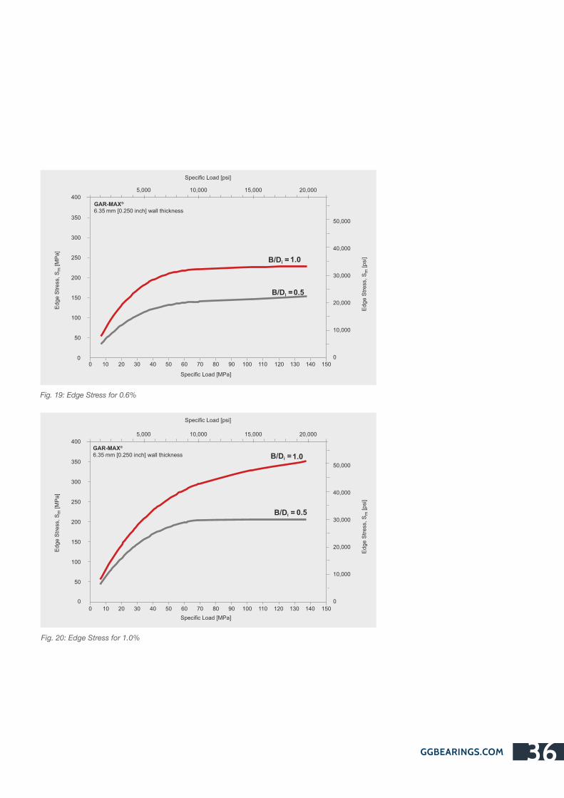
GGBEARINGS.COM 36
Specific Load [MPa]
Edge S
tress
, S
m[M
Pa]
Specific Load [psi]
B/D = 1.0i
B/D =0.5i
0
5,000 10,000 15,000 20,000
Edge S
tress
, S
m[p
si]
0 10 20 30 40 50 60 70 80 90 100 110 120 130 140 150
50
100
150
200
250
300
350
400
0
10,000
20,000
30,000
40,000
50,000
®GAR-MAX 6.35 mm [0.250 inch] wall thickness
Specific Load [MPa]
Edge S
tress
, S
m[M
Pa]
Specific Load [psi]
B/D =1.0i
B/D = 0.5i
0
5,000 10,000 15,000 20,000
Edge S
tress
, S
m[p
si]
0 10 20 30 40 50 60 70 80 90 100 110 120 130 140 150
50
100
150
200
250
300
350
400
0
10,000
20,000
30,000
40,000
50,000
®GAR-MAX6.35 mm [0.250 inch] wall thickness
Fig. 19: Edge Stress for 0.6%
Fig. 20: Edge Stress for 1.0%

Fig. 21: Fittings of bearings
7.0 Installation and Machining
The retention of GGB filament wound bearings in
metal housings is excellent due to the high material
stiffness and a thermal expansion rate similar to steel.
The press fits used for bronze bearings are adequate
for filament wound bearings in most cases. In general,
filament wound bearings can be directly mounted in
housings designed for bronze bearings. The bearing
will close in by an amount equal to the measure of
interference with the housing. This close-in must be
considered when calculating the installed bore and
corresponding shaft diameter.
7.1 Installation
Housing
1.5mm
[0.060 inch]
Nominal bearing lengthminus 1 mm [0.04 inch]
Arbor
Pilot dia. = Nominal bearingbore dia. minus 0.38/0.64 mm [0.015/0.025 inch]
15°-20°
®The HPMB bearing’s liner is easily machined with commonly available single-point tools. In standard form, maximum
allowable machining depth is 1 mm [0.04 inch] (on diameter), which can be increased up to 3 mm [0.118 inches]
(on diameter) by special request.
® HPMB may be machined in a single pass to the required final inside diameter and it shall be machined dry.
Documented machining parameters include carbide inserts with a cutting radius 3 - 10 mm [0.118 - 0.394 inches]
to machine the liner with a surface speed of 1.25 – 3.5 m/s [0.049 - 0.138 inches] and a traverse speed of
0.13 mm [0.0005 inches] /revolution.
® HPMB bearings can be ID-machined either by GGB or the end user.
To obtain maximum bearing performance, it is strongly recommended that HPMB bearings operate only after
being machined in the inner diameter. The minimum recommended machining depth is 0.2 mm [0.008 inches]
on the diameter.
®7.2 Machining of HPMB Bearings
GGBEARINGS.COM37
an EnPro Industries company
The Global Leader
in High Performance Bearing Solutions
GGBEARINGS.COM 38
Length
Abrasive cut-of wheels produce the best results when
cutting lengths of GGB filament wound bearings.
When using a lathe to cut of lengths, we recommend
using a carbide tool due to the abrasive nature of the
fiberglass/epoxy outer shell.
Water mist or exhaust dust collectors should be used
to minimize dust in the work area.
Outer Diameter Grinding is the preferred method of altering the outer
diameter; however, carbide lathe tools can also be used.
Inner Diameter ® HPMB bearing’s liner is easily machined with a commonly
available single point tools.
® Please see Machining of HPMB Bearings on page 37.
TM TM GAR-FIL and HPF bearings can be sized on the inner diameter. We recommend specifying 0.76 mm
[0.030 inches] or thicker ape liner when ordering bearings TM TM that will be bored. When lathe boring a GAR-FIL or HPF
bearing, you should first install the bearing into a rigid
housing and bore using high speed and low feed rate. TM TMGAR-FIL and HPF bearings can also be reamed and
broached.
Deburring
Emery cloth is effective in removing burrs from the
outer diameter of GGB filament wound bearings.
®To remove frayed fibers from the ID of GAR-MAX , TM TM ® TM HSG , MLG , HPMB and HPM bearings, a small
hand held grinder is preferred.
TM TMThe inner diameter of GAR-FIL or HPF bearings can be deburred by a sharp cutting tool or emery cloth.
Drilling
Carbide drills should be used for drilling GGB filament
wound bearings.
® TM TM ®When drilling GAR-MAX , HSG , MLG , HPMB and TMHPM bearings, the inner diameter must be supported
with a mandrel, and a flat tipped drill or end mill
should be used.
7.3 Fitting

8.0 Standard Products
1/8" wall series
To order, specify bearing product prefix and size number plus suffix for desired length (in multiples of 1/16”).
e.g. GM2428-032 is a 1.5” ID x 1.75” OD x 2” long GAR-MAX® bearing.
B
Do
Di
Length tolerance table
B
<3 inch ≥3 to <6 inch ≥6 inch
Di
<3 inch ±0.010 inch ±0.020 inch ±0.030 inch
≥3 to<6 inch ±0.020 inch ±0.020 inch ±0.030 inch
Bearing PartNumber
NominalSize
ID x ODD x Di o
Bearing IDDi
Bearing ODDo
Recommended Sizes RunningClearance
CDGM, GF, HSG, MLGShaft Dia. D
J
HousingDia. D
H
0812-xxx ½ x ¾ 0.50400.5070
0.75350.7515
0.50000.4995
0.75000.7505
0.00050.0065
1014-xxx 5/8 x 7/80.62900.6320
0.87850.8765
0.62500.6245
0.87500.8755
0.00050.0065
1216-xxx ¾ x 1 0.75400.7570
1.00351.0015
0.75000.7495
1.00001.0005
0.00050.0065
1418-xxx 7/8 x 11/80.87900.8820
1.12851.1265
0.87500.8745
1.12501.1255
0.00050.0065
1620-xxx 1 x 1¼ 1.00401.0070
1.25351.2515
1.00000.9995
1.25001.2505
0.00050.0065
1822-xxx 11/8 x 13/81.12901.1320
1.37851.3765
1.12501.1245
1.37501.3755
0.00050.0065
2024-xxx 1¼ x 1½ 1.25401.2570
1.50351.5015
1.25001.2495
1.50001.5005
0.00050.0065
2226-xxx 13/8 x 15/81.37901.3820
1.62851.6265
1.37501.3745
1.62501.6255
0.00050.0065
2428-xxx 1½ x 1¾ 1.50401.5070
1.75351.7515
1.50001.4995
1.75001.7505
0.00050.0065
2630-xxx 15/8 x 17/81.62901.6320
1.87851.8765
1.62501.6245
1.87501.8755
0.00050.0065
2832-xxx 1 ¾ x 2 1.75501.7580
2.00352.0015
1.75001.7495
2.00002.0005
0.00150.0075
3034-xxx 17/8 x 21/81.88001.8830
2.12852.1265
1.87501.8745
2.12502.1255
0.00150.0075
3236-xxx 2 x 2 ¼ 2.00552.0095
2.25452.2525
2.00001.9995
2.25002.2510
0.00100.0085
3438-xxx 21/8 x 2¼ 2.13052.1345
2.37952.3775
2.12502.1245
2.37502.3760
0.00100.0085
3640-xxx 2¼ x 2½ 2.25552.2595
2.50452.5025
2.25002.2495
2.50002.5010
0.00100.0085
3842-xxx 23/8 x 25/82.38052.3845
2.62952.6275
2.37502.3740
2.62502.6260
0.00100.0090
® TM TM TM8.1 GAR-MAX , GAR-FIL , HSG , MLG (Inch Sizes)
an EnPro Industries company
The Global Leader
in High Performance Bearing Solutions

Bearing PartNumber
NominalSize
ID x ODBearing ID Bearing OD
Recommended Sizes RunningClearance
GM, GF, HSG, MLGShaft Dia. D
J
HousingDia. D
H
4044-xxx 2½ x 2¾2.50602.5100
2.75452.7525
2.50002.4990
2.75002.7510
0.00150.0095
4448-xxx 2¾ x 3 2.75602.7600
3.00503.0030
2.75002.7490
3.00003.0015
0.00100.0095
4852-xxx 3 x 3¼ 3.00653.0105
3.25503.2530
3.00002.9990
3.25003.2515
0.00150.0100
5256-xxx 3¼ x 3½3.25653.2605
3.50553.5035
3.25003.2490
3.50003.5020
0.00100.0100
5660-xxx 3½ x 3¾3.50653.5105
3.75553.7535
3.50003.4990
3.75003.7520
0.00100.0100
6064-xxx 3¾ x 43.75653.7605
4.00554.0035
3.75003.7490
4.00004.0020
0.00100.0100
6468-xxx 4 x 4¼4.00904.0140
4.25704.2540
4.00003.9990
4.25004.2520
0.00200.0130
6872-xxx 4¼ x 4½4.25904.2640
4.50704.5040
4.25004.2490
4.50004.5020
0.00200.0130
7276-xxx 4½ x 4¾ 4.50904.5140
4.75704.7540
4.50004.4990
4.75004.7520
0.00200.0130
7680-xxx 4¾ x 54.75904.7640
5.00705.0040
4.75004.7490
5.00005.0020
0.00200.0130
8084-xxx 5 x 5¼ 5.00905.0140
5.25705.2540
5.00004.9990
5.25005.2520
0.00200.0130
8488-xxx 5¼ x 5½5.25905.2640
5.50705.5040
5.25005.2490
5.50005.5020
0.00200.0130
8892-xxx 5½ x 5¾5.50905.5140
5.75705.7540
5.50005.4990
5.75005.7520
0.00200.0130
9296-xxx 5¾ x 6 5.75905.7640
6.00706.0040
5.75005.7490
6.00006.0020
0.00200.0130
96100-xxx 6 x 6¼6.01206.0180
6.25906.2550
6.00005.9985
6.25006.2520
0.00300.0165
All dimensions in inches. Additional sizes available - please consult with GGB for further details.
GGBEARINGS.COM 40
D x Di o
Di Do CD

To order, specify bearing product prefix and size number plus suffix for desired length (in multiples of 1/16”).
e.g. GM2432-032 is a 1.5” ID x 2” OD x 2” long GAR-MAX® bearing.
Bearing PartNumber
NominalSize
ID x ODBearing ID Bearing OD
Recommended Sizes RunningClearance
GM, GF, HSG, MLGShaft Dia. D
J
HousingDia. D
H
0816-xxx 1/2 x 1 0.50400.5070
1.00351.0015
0.50000.4995
1.00001.0005
0.00050.0065
1018-xxx 5/8 x 11/80.62900.6320
1.12851.1265
0.62500.6245
1.12501.1255
0.00050.0065
1220-xxx 3/4 x 11/40.75400.7570
1.25351.2515
0.75000.7495
1.25001.2505
0.00050.0065
1422-xxx 7/8 x 13/80.87900.8820
1.37851.3765
0.87500.8745
1.37501.3755
0.00050.0065
1624-xxx 1 x 11/21.00401.0070
1.50351.5015
1.00000.9995
1.50001.5005
0.00050.0065
1826-xxx 11/8 x 15/81.12901.1320
1.62851.6265
1.12501.1245
1.62501.6255
0.00050.0065
2028-xxx 11/4 x 13/41.25401.2570
1.75351.7515
1.25001.2495
1.75001.7505
0.00050.0065
2230-xxx 13/8 x 17/81.37901.3820
1.87851.8765
1.37501.3745
1.87501.8755
0.00050.0065
2432-xxx 11/2 x 2 1.50401.5070
2.00352.0015
1.50001.4995
2.00002.0005
0.00050.0065
2634-xxx 15/8 x 21/81.62901.6320
2.12852.1265
1.62501.6245
2.12502.1255
0.00050.0065
2836-xxx 13/4 x 21/41.75501.7580
2.25452.2525
1.75001.7495
2.25002.2510
0.00050.0070
3038-xxx 17/8 x 23/81.88001.8830
2.37952.3775
1.87501.8745
2.37502.3760
0.00050.0070
3240-xxx 2 x 21/22.00552.0095
2.50452.5025
2.00001.9995
2.50002.5010
0.00100.0085
3442-xxx 21/8 x 25/82.13052.1345
2.62952.6275
2.12502.1245
2.62502.6260
0.00100.0085
3644-xxx 21/4 x 23/42.25552.2595
2.75452.7525
2.25002.2495
2.75002.7510
0.00100.0085
3846-xxx 23/8 x 27/82.38052.3845
2.87952.8775
2.37502.3740
2.87502.8760
0.00100.0090
D x Di o
Di Do CD
an EnPro Industries company
The Global Leader
in High Performance Bearing Solutions
1/4" wall series
B
Do
Di
Length tolerance table
B
<3 inch ≥3 to <6 inch ≥6 inch
Di
<3 inch ±0.010 inch ±0.020 inch ±0.030 inch
≥3 to<6 inch ±0.020 inch ±0.020 inch ±0.030 inch
® TM TM TMGAR-MAX , GAR-FIL , HSG , MLG (Inch Sizes)

GGBEARINGS.COM 42
Bearing PartNumber
NominalSize
ID x ODBearing ID Bearing OD
Recommended Sizes RunningClearance
GM, GF, HSG, MLGShaft Dia. D
J
HousingDia. D
H
4048-xxx 21/2 x 32.50602.5100
3.00503.0030
2.50002.4990
3.00003.0015
0.00100.0095
4452-xxx 23/4 x 31/42.75602.7600
3.25503.2530
2.75002.7490
3.25003.2515
0.00100.0095
4856-xxx 3 x 31/23.00653.0105
3.50553.5035
3.00002.9990
3.50003.5020
0.00100.0100
5260-xxx 31/4 x 33/43.25653.2605
3.75553.7535
3.25003.2490
3.75003.7520
0.00100.0100
5664-xxx 31/2 x 43.50653.5105
4.00554.0035
3.50003.4990
4.00004.0020
0.00100.0100
6068-xxx 33/4 x 41/43.75653.7605
4.25554.2535
3.75003.7490
4.25004.2520
0.00100.0100
6472-xxx 4 x 41/24.00904.0140
4.50704.5040
4.00003.9990
4.50004.5020
0.00200.0130
6876-xxx 41/4 x 43/44.25904.2640
4.75704.7540
4.25004.2490
4.75004.7520
0.00200.0130
7280-xxx 41/2 x 54.50904.5140
5.00705.0040
4.50004.4990
5.00005.0020
0.00200.0130
7684-xxx 43/4 x 51/44.75904.7640
5.25705.2540
4.75004.7490
5.25005.2520
0.00200.0130
8088-xxx 5 x 51/25.00905.0140
5.50705.5040
5.00004.9990
5.50005.5020
0.00200.0130
8492-xxx 51/4 x 53/45.25905.2640
5.75705.7540
5.25005.2490
5.75005.7520
0.00200.0130
8896-xxx 51/2 x 65.50905.5140
6.00706.0040
5.50005.4990
6.00006.0020
0.00200.0130
92100-xxx 53/4 x 61/45.75905.7640
6.25706.2540
5.75005.7490
6.25006.2520
0.00200.0130
96104-xxx 6 x 61/26.01206.0180
6.50906.5050
6.00005.9985
6.50006.5020
0.00300.0165
All dimensions in inches. Additional sizes available - please consult with GGB for futher details.
D x Di o
Di Do CD

2.5 mm wall series
To order, specify bearing ID, OD and length size number (in millimeters) plus product suffix.
e.g. 253020GM is a 25 mm ID x 30 mm OD x 20 mm long GAR-MAX® bearing.
B
Do
Di
Length tolerance table
B
<75 mm ≥75 to <150 mm ≥150 mm
DI
<75 mm -0.50 mm -1.00 mm -1.50 mm
≥75 to <150 mm -1.00 mm -1.00 mm -1.50 mm
Bearing PartNumber
NominalSize
ID x ODBearing ID Bearing OD
Recommended Sizes RunningClearance
GM, GF, HSG, MLGShaft
Dia. [h8] DJ
HousingDia. [H7] D
H
1217xx 12 x 17 12.11012.190
17.09017.040
12.00011.973
17.00017.018
0.0200.195
1520xx 15 x 20 15.11015.190
20.09020.040
15.00014.973
20.00020.021
0.0200.198
1621xx 16 x 21 16.11016.190
21.09021.040
16.00015.973
21.00021.021
0.0200.198
1823xx 18 x 23 18.11018.190
23.09023.040
18.00017.973
23.00023.021
0.0200.198
2025xx 20 x 25 20.11020.190
25.09025.040
20.00019.967
25.00025.021
0.0200.204
2227xx 22 x 27 22.11022.190
27.09027.040
22.00021.967
27.00027.021
0.0200.204
2530xx 25 x 30 25.11025.190
30.09030.040
25.00024.967
30.00030.021
0.0200.204
2833xx 28 x 33 28.11528.195
33.09533.045
28.00027.967
33.00033.025
0.0200.208
3035xx 30 x 35 30.11530.195
35.09535.045
30.00029.967
35.00035.025
0.0200.208
3540xx 35 x 40 35.11535.195
40.09540.045
35.00034.961
40.00040.025
0.0200.214
4045xx 40 x 45 40.11540.195
45.09545.045
40.00039.961
45.00045.025
0.0200.214
4550xx 45 x 50 45.12545.225
50.10050.050
45.00044.961
50.00050.025
0.0250.239
5055xx 50 x 55 50.12550.225
55.10055.055
50.00049.961
55.00055.030
0.0250.239
5560xx 55 x 60 55.14055.240
60.11560.065
55.00054.954
60.00060.030
0.0250.251
6065xx 60 x 65 60.14060.240
65.11565.065
60.00059.954
65.00065.030
0.0250.251
6570xx 65 x 70 65.14065.240
70.11570.065
65.00064.954
70.00070.030
0.0250.251
® TM TM TMGAR-MAX , GAR-FIL , HSG , MLG (Metric Sizes)
D x Di o
Di Do CD
an EnPro Industries company
The Global Leader
in High Performance Bearing Solutions

Bearing PartNumber
NominalSize
ID x ODBearing ID Bearing OD
Recommended Sizes RunningClearance
GM, GF, HSG, MLGShaft
Dia. [h8] DJ
HousingDia. [H7] D
H
7075xx 70 x 75 70.14570.245
75.11575.065
70.00069.954
75.00075.030
0.0300.256
7580xx 75 x 80 75.16575.265
80.12580.070
75.00074.954
80.00080.030
0.0400.271
8085xx 80 x 85 80.16580.265
85.12585.075
80.00079.954
85.00085.035
0.0400.271
8590xx 85 x 90 85.16585.265
90.12590.075
85.00084.946
90.00090.035
0.0400.279
9095xx 90 x 95 90.17590.275
95.13595.085
90.00089.946
95.00095.035
0.0400.279
95100xx 95 x 100 95.17595.300
100.135100.085
95.00094.946
100.000100.035
0.0400.304
100105xx 100 x 105 100.175100.300
105.135105.085
100.00099.946
105.000105.035
0.0400.304
110115xx 110 x 115 110.175110.300
115.135115.080
110.000109.946
115.000115.035
0.0400.309
120125xx 120 x 125 120.205120.330
125.165125.105
120.000119.946
125.000125.040
0.0400.319
130135xx 130 x 135 130.205130.330
135.165135.090
130.000129.937
135.000135.040
0.0400.343
140145xx 140 x 145 140.205140.330
145.165145.090
140.000139.937
145.000145.040
0.0400.343
150155xx 150 x 155 150.205150.330
155.165155.090
150.000149.937
155.000155.040
0.0400.343
All dimensions in Millimeters. Additional sizes available - please consult with GGB for futher details.
GGBEARINGS.COM 44
D x Di o
Di Do CD

5 mm wall series
To order, specify bearing ID, OD and length size number (in millimeters) plus product suffix.
e.g. 253520GM is a 25 mm ID x 30 mm OD x 20 mm long GAR-MAX® bearing.
Length tolerance table
B
<75 mm ≥75 to <150 mm ≥150 mm
Di
<75 mm -0.50 mm -1.00 mm -1.50 mm
≥75 to <150 mm -1.00 mm -1.00 mm -1.50 mm
Bearing PartNumber
NominalSize
ID x OD
Recommended Sizes RunningClearance
GM, GF, HSG, MLGShaft
Dia. [h8] DJ
HousingDia. [H7] D
H
1222xx 12 x 22 12.11012.190
22.09022.040
12.00011.973
22.00022.021
0.0200.198
1525xx 15 x 25 15.11015.190
25.09025.040
15.00014.973
25.00025.021
0.0200.198
1626xx 16 x 26 16.11016.190
26.09026.040
16.00015.973
26.00026.021
0.0200.198
1828xx 18 x 28 18.11018.190
28.09028.040
18.00017.973
28.00028.021
0.0200.198
2030xx 20 x 30 20.11020.190
30.09030.040
20.00019.967
30.00030.021
0.0200.204
2232xx 22 x 32 22.11522.195
32.09532.045
22.00021.967
32.00032.025
0.0200.208
2535xx 25 x 35 25.11525.195
35.09535.045
25.00024.967
35.00035.025
0.0200.208
2838xx 28 x 38 28.11528.195
38.09538.045
28.00027.967
38.00038.025
0.0200.208
3040xx 30 x 40 30.11530.195
40.09540.045
30.00029.967
40.00040.025
0.0200.208
3545xx 35 x 45 35.11535.195
45.09545.045
35.00034.961
45.00045.025
0.0200.214
4050xx 40 x 50 40.11540.195
50.09550.045
40.00039.961
50.00050.025
0.0200.214
4555xx 45 x 55 45.13045.230
55.10555.055
45.00044.961
55.00055.030
0.0250.244
5060xx 50 x 60 50.13050.230
60.10560.055
50.00049.961
60.00060.030
0.0250.244
5565xx 55 x 65 55.14055.240
65.11565.065
55.00054.954
65.00065.030
0.0250.251
6070xx 60 x 70 60.14060.240
70.11570.065
60.00059.954
70.00070.030
0.0250.251
6575xx 65 x 75 65.14065.240
75.11575.065
65.00064.954
75.00075.030
0.0250.251
® TM TM TMGAR-MAX , GAR-FIL , HSG , MLG (Metric Sizes)
D x Di o
Bearing IDDi
Bearing ODDo CD
an EnPro Industries company
The Global Leader
in High Performance Bearing Solutions
B
Do
Di

GGBEARINGS.COM 46
Bearing PartNumber
NominalSize
ID x ODBearing ID Bearing OD
Recommended Sizes RunningClearance
GM, GF, HSG, MLGShaft
Dia. [h8] DJ
HousingDia. [H7] D
H
7080xx 70 x 80 70.14570.245
80.11580.065
0.0300.256
7585xx 75 x 85 75.16575.265
85.12585.075
0.0400.271
8090xx 80 x 90 80.16580.265
90.12590.075
0.0400.271
8595xx 85 x 95 85.16585.265
95.12595.075
0.0400.279
90100xx 90 x 100 90.17590.275
100.135100.085
0.0400.279
95105xx 95 x 105 95.17595.300
105.135105.085
0.0400.304
100110xx 100 x 110 100.175100.300
110.135110.085
0.0400.304
110120xx 110 x 120 110.175110.300
120.135120.085
0.0400.304
120130xx 120 x 130 120.205120.330
130.165130.090
0.0400.334
130140xx 130 x 140 130.205130.330
140.165140.090
0.0400.343
140150xx 140 x 150 140.205140.330
150.165150.090
0.0400.343
150160xx 150 x 160 150.205150.330
160.165160.090
70.00069.954
75.00074.954
80.00079.954
85.00084.946
90.00089.946
95.00094.946
100.00099.946
110.000109.946
120.000119.946
130.000129.937
140.000139.937
150.000149.937
80.00080.030
85.00085.035
90.00090.035
95.00095.035
100.000100.035
105.000105.035
110.000110.035
120.000120.035
130.000130.040
140.000140.040
150.000150.040
160.000160.040
0.0400.343
All dimensions in Millimeters. Additional sizes available - please consult with GGB for futher details.
D x Di o
Di Do CD

To order, specify bearing ID, OD and length size number (in millimeters) plus product suffix.
e.g. 253020GM is a 25 mm ID x 30 mm OD x 20 mm long GAR-MAX® bearing.
Length tolerance table
B
<75 mm ≥75 to <150 mm ≥150 mm
Di
<75 mm -0.50 mm -1.00 mm -1.50 mm
≥75 to <150 mm -1.00 mm -1.00 mm -1.50 mm
8.3 European GAR-MAX® Size Range
Part NumberNominal Size
ID x OD x Length, D x D x Bi o
Bearing ID, Di Bearing OD, Do Shaft, h8 Housing, H7Clearance
(after assembly in H7 housing)
162015GM 16 x 20 x 15 16.110 / 16.190 20.090 / 20.040 16.000 / 15.973 20.000 / 20.021 0.020 / 0.198
162020GM 16 x 20 x 20 16.110 / 16.190 20.090 / 20.040 16.000 / 15.973 20.000 / 20.021 0.020 / 0.198
202415GM 20 x 24 x 15 20.110 / 20.190 24.090 / 24.040 20.000 / 19.967 24.000 / 24.021 0.020 / 0.204
202420GM 20 x 24 x 20 20.110 / 20.190 24.090 / 24.040 20.000 / 19.967 24.000 / 24.021 0.020 / 0.204
202425GM 20 x 24 x 25 20.110 / 20.190 24.090 / 24.040 20.000 / 19.967 24.000 / 24.021 0.020 / 0.204
222620GM 22 x 26 x 20 22.110 / 22.190 26.090 / 26.040 22.000 / 21.967 26.000 / 26.021 0.020 / 0.204
222625GM 22 x 26 x 25 22.110 / 22.190 26.090 / 26.040 22.000 / 21.967 26.000 / 26.021 0.020 / 0.204
253020GM 25 x 30 x 20 25.110 / 25.190 30.090 / 30.040 25.000 / 24.967 30.000 / 30.021 0.020 / 0.204
253025GM 25 x 30 x 25 25.110 / 25.190 30.090 / 30.040 25.000 / 24.967 30.000 / 30.021 0.020 / 0.204
253030GM 25 x 30 x 30 25.110 / 25.190 30.090 / 30.040 25.000 / 24.967 30.000 / 30.021 0.020 / 0.204
283422GM 28 x 34 x 22 28.115 / 28.195 34.095 / 34.045 28.000 / 27.967 34.000 / 34.025 0.020 / 0.208
303620GM 30 x 36 x 20 30.115 / 30.195 36.095 / 36.045 30.000 / 29.967 36.000 / 36.025 0.020 / 0.208
303630GM 30 x 36 x 30 30.115 / 30.195 36.095 / 36.045 30.000 / 29.967 36.000 / 36.025 0.020 / 0.208
303636GM 30 x 36 x 36 30.115 / 30.195 36.095 / 36.045 30.000 / 29.967 36.000 / 36.025 0.020 / 0.208
303640GM 30 x 36 x 40 30.115 / 30.195 36.095 / 36.045 30.000 / 29.967 36.000 / 36.025 0.020 / 0.208
303650GM 30 x 36 x 50 30.115 / 30.195 36.095 / 36.045 30.000 / 29.967 36.000 / 36.025 0.020 / 0.208
354130GM 35 x 41 x 30 35.115 / 35.195 41.095 / 41.045 35.000 / 34.961 41.000 / 41.025 0.020 / 0.214
354135GM 35 x 41 x 35 35.115 / 35.195 41.095 / 41.045 35.000 / 34.961 41.000 / 41.025 0.020 / 0.214
354140GM 35 x 41 x 40 35.115 / 35.195 41.095 / 41.045 35.000 / 34.961 41.000 / 41.025 0.020 / 0.214
354150GM 35 x 41 x 50 35.115 / 35.195 41.095 / 41.045 35.000 / 34.961 41.000 / 41.025 0.020 / 0.214
404820GM 40 x 48 x 20 40.115 / 40.195 48.095 / 48.045 40.000 / 39.961 48.000 / 48.025 0.020 / 0.214
404830GM 40 x 48 x 30 40.115 / 40.195 48.095 / 48.045 40.000 / 39.961 48.000 / 48.025 0.020 / 0.214
an EnPro Industries company
The Global Leader
in High Performance Bearing Solutions
B
Do
Di

All dimensions in Millimeters. Additional sizes available - please consult with GGB for futher details.
GGBEARINGS.COM 48
404840GM 40 x 48 x 40 40.115 / 40.195 48.095 / 48.045 40.000 / 39.961 48.000 / 48.025 0.020 / 0.214
404850GM 40 x 48 x 50 40.115 / 40.195 48.095 / 48.045 40.000 / 39.961 48.000 / 48.025 0.020 / 0.214
455330GM 45 x 53 x 30 45.130 / 45.230 53.105 / 53.055 45.000 / 44.961 53.000 / 53.030 0.025 / 0.244
455340GM 45 x 53 x 40 45.130 / 45.230 53.105 / 53.055 45.000 / 44.961 53.000 / 53.030 0.025 / 0.244
455345GM 45 x 53 x 45 45.130 / 45.230 53.105 / 53.055 45.000 / 44.961 53.000 / 53.030 0.025 / 0.244
455350GM 45 x 53 x 50 45.130 / 45.230 53.105 / 53.055 45.000 / 44.961 53.000 / 53.030 0.025 / 0.244
455360GM 45 x 53 x 60 45.130 / 45.230 53.105 / 53.055 45.000 / 44.961 53.000 / 53.030 0.025 / 0.244
505830GM 50 x 58 x 30 50.130 / 50.230 58.105 / 58.055 50.000 / 49.961 58.000 / 58.030 0.025 / 0.244
505840GM 50 x 58 x 40 50.130 / 50.230 58.105 / 58.055 50.000 / 49.961 58.000 / 58.030 0.025 / 0.244
505850GM 50 x 58 x 50 50.130 / 50.230 58.105 / 58.055 50.000 / 49.961 58.000 / 58.030 0.025 / 0.244
505860GM 50 x 58 x 60 50.130 / 50.230 58.105 / 58.055 50.000 / 49.961 58.000 / 58.030 0.025 / 0.244
556330GM 55 x 63 x 30 55.140 / 55.240 63.115 / 63.065 55.000 / 54.954 63.000 / 63.030 0.025 / 0.251
556340GM 55 x 63 x 40 55.140 / 55.240 63.115 / 63.065 55.000 / 54.954 63.000 / 63.030 0.025 / 0.251
556360GM 55 x 63 x 60 55.140 / 55.240 63.115 / 63.065 55.000 / 54.954 63.000 / 63.030 0.025 / 0.251
607030GM 60 x 70 x 30 60.140 / 60.240 70.115 / 70.065 60.000 / 59.954 70.000 / 70.030 0.025 / 0.251
607040GM 60 x 70 x 40 60.140 / 60.240 70.115 / 70.065 60.000 / 59.954 70.000 / 70.030 0.025 / 0.251
607045GM 60 x 70 x 45 60.140 / 60.240 70.115 / 70.065 60.000 / 59.954 70.000 / 70.030 0.025 / 0.251
607050GM 60 x 70 x 50 60.140 / 60.240 70.115 / 70.065 60.000 / 59.954 70.000 / 70.030 0.025 / 0.251
607060GM 60 x 70 x 60 60.140 / 60.240 70.115 / 70.065 60.000 / 59.954 70.000 / 70.030 0.025 / 0.251
657550GM 65 x 75 x 50 65.140 / 65.240 75.115 / 75.065 65.000 / 64.954 75.000 / 75.030 0.025 / 0.251
708040GM 70 x 80 x 40 70.145 / 70.245 80.115 / 80.065 70.000 / 69.954 80.000 / 80.030 0.030 / 0.256
708050GM 70 x 80 x 50 70.145 / 70.245 80.115 / 80.065 70.000 / 69.954 80.000 / 80.030 0.030 / 0.256
708055GM 70 x 80 x 55 70.145 / 70.245 80.115 / 80.065 70.000 / 69.954 80.000 / 80.030 0.030 / 0.256
708060GM 70 x 80 x 60 70.145 / 70.245 80.115 / 80.065 70.000 / 69.954 80.000 / 80.030 0.030 / 0.256
708070GM 70 x 80 x 70 70.145 / 70.245 80.115 / 80.065 70.000 / 69.954 80.000 / 80.030 0.030 / 0.256
708080GM 70 x 80 x 80 70.145 / 70.245 80.115 / 80.065 70.000 / 69.954 80.000 / 80.030 0.030 / 0.256
758550GM 75 x 85 x 50 75.165 / 75.265 85.125 / 85.075 75.000 / 74.954 85.000 / 85.035 0.040 / 0.271
758560GM 75 x 85 x 60 75.165 / 75.265 85.125 / 85.075 75.000 / 74.954 85.000 / 85.035 0.040 / 0.271
758570GM 75 x 85 x 70 75.165 / 75.265 85.125 / 85.075 75.000 / 74.954 85.000 / 85.035 0.040 / 0.271
758580GM 75 x 85 x 80 75.165 / 75.265 85.125 / 85.075 75.000 / 74.954 85.000 / 85.035 0.040 / 0.271
809050GM 80 x 90 x 50 80.165 / 80.265 90.125 / 90.075 80.000 / 79.954 90.000 / 90.035 0.040 / 0.271
809060GM 80 x 90 x 60 80.165 / 80.265 90.125 / 90.075 80.000 / 79.954 90.000 / 90.035 0.040 / 0.271
809070GM 80 x 90 x 70 80.165 / 80.265 90.125 / 90.075 80.000 / 79.954 90.000 / 90.035 0.040 / 0.271
809080GM 80 x 90 x 80 80.165 / 80.265 90.125 / 90.075 80.000 / 79.954 90.000 / 90.035 0.040 / 0.271
859560GM 85 x 95 x 60 85.165 / 85.265 95.125 / 95.075 85.000 / 84.946 95.000 / 95.035 0.040 / 0.279
859580GM 85 x 95 x 80 85.165 / 85.265 95.125 / 95.075 85.000 / 84.946 95.000 / 95.035 0.040 / 0.279
9010570GM 90 x 105 x 70 90.175 / 90.275 105.135 / 105.085 90.000 / 89.946 105.000 / 105.035 0.040 / 0.279
10011580GM 100 x 115 x 80 100.175 / 100.300 115.135 / 115.085 100.000 / 99.946 115.000 / 115.035 0.040 / 0.304
100115100GM 100 x 115 x 100 100.175 / 100.300 115.135 / 115.085 100.000 / 99.946 115.000 / 115.035 0.040 / 0.304
100115120GM 100 x 115 x 120 100.175 / 100.300 115.135 / 115.085 100.000 / 99.946 115.000 / 115.035 0.040 / 0.304
110125100GM 110 x 125 x 100 110.205 / 110.330 125.165 / 125.090 110.000 / 109.946 125.000 / 125.040 0.040 / 0.334
110125120GM 110 x 125 x 120 110.205 / 110.330 125.165 / 125.090 110.000 / 109.946 125.000 / 125.040 0.040 / 0.334
120135100GM 120 x 135 x 100 120.205 / 120.330 135.165 / 135.090 120.000 / 119.946 135.000 / 135.040 0.040 / 0.334
120135120GM 120 x 135 x 120 120.205 / 120.330 135.165 / 135.090 120.000 / 119.946 135.000 / 135.040 0.040 / 0.334
Part Number ID x OD x Length D x D x Bi o
Bearing ID, Di Bearing OD, Do Shaft, h8 Housing, H7 (after assembly in H7 housing)

8.4 MEGALIFE XT Thrust Washers, Inch sizesTo order, specify MWXT size number plus suffix for desired thickness (062, 080, 125).
e.g. MWXT1632-080 is a 1" ID x 2" OD x 0.080" thick MEGALIFE XT thrust washer.
Part NumberNominal Size
ID x ODNominal
Thickness
MWXT0816-xxx 1/2 x 1 0.062, 0.080
MWXT1020-xxx 5/8 x 11/4 0.062, 0.080, 0.125
MWXT1224-xxx 3/4 x 11/2 0.062, 0.080, 0.125
MWXT1428-xxx 7/8 x 13/4 0.062, 0.080, 0.125
MWXT1632-xxx 1 x 2 0.062, 0.080, 0.125
MWXT1834-xxx 11/8 x 21/8 0.062, 0.080, 0.125
MWXT2036-xxx 11/4 x 21/4 0.062, 0.080, 0.125
MWXT2238-xxx 13/8 x 23/8 0.062, 0.080, 0.125
MWXT2440-xxx 11/2 x 2 1/2 0.062, 0.080, 0.125
MWXT2642-xxx 1 5/8 x 2 5/8 0.062, 0.080, 0.125
MWXT2844-xxx 13/4 x 23/4 0.062, 0.080, 0.125
MWXT3248-xxx 2 x 3 0.062, 0.080, 0.125
0.062, 0.080, 0.125
0.062, 0.080, 0.125
0.062, 0.080, 0.125
0.062, 0.080, 0.125
MWXT3652-xxx 21/4 x 31/4
MWXT4060-xxx 21/2 x 33/4
MWXT4464-xxx 23/4 x 4
MWXT4872-xxx 3 x 41/2
All dimensions in inches.Additional sizes available - please consult with GGB for futher details.
GGBEARINGS.COM49
an EnPro Industries company
The Global Leader
in High Performance Bearing Solutions

GGBEARINGS.COM 50
8.5 MEGALIFE XT Thrust Washers, Metric sizesTo order, specify MWXTM size number plus suffix for desired thickness (15; 20; 30).
e.g. MWXTM2244-20 is a 22 mm ID x 44 mm OD x 2 mm thick MEGALIFE XT thrust washer.
Part NumberNominal Size
ID x ODNominal
Thickness
MWXTM1224-xx 12 x 24 1.5, 2.0 mm
MWXTM1530-xx 15 x 30 1.5, 2.0, 3.0 mm
MWXTM1836-xx 18 x 36 1.5, 2.0, 3.0 mm
MWXTM2040-xx 20 x 40 1.5, 2.0, 3.0 mm
MWXTM2244-xx 22 x 44 1.5, 2.0, 3.0 mm
MWXTM2550-xx 25 x 50 1.5, 2.0, 3.0 mm
MWXTM3055-xx 30 x 55 1.5, 2.0, 3.0 mm
MWXTM3560-xx 35 x 60 1.5, 2.0, 3.0 mm
MWXTM4065-xx 40 x 65 1.5, 2.0, 3.0 mm
MWXTM4570-xx 45 x 70 1.5, 2.0, 3.0 mm
MWXTM5075-xx 50 x 75 1.5, 2.0, 3.0 mm
1.5, 2.0, 3.0 mm
1.5, 2.0, 3.0 mm
1.5, 2.0, 3.0 mm
1.5, 2.0, 3.0 mm
1.5, 2.0, 3.0 mm
MWXTM5580-xx 55 x 80
MWXTM6085-xx 60 x 85
MWXTM6595-xx 65 x 95
MWXTM70100-xx 70 x 100
MWXTM75115-xx 75 x 115
All dimensions in Millimeters. Additional sizes available - please consult with GGB for futher details.

GGBEARINGS.COM51
8.6 Datasheet
DIMENSIONS (mm)
Inside diameter D i
Outside diameter Do
Length B
Flange diameter D
Flange thickness Bfl
fl
Wall thickness ST
Length of slideplate L
Width of slideplate W
Thickness of slideplate SS
CUSTOMER INFORMATION
Company
Street
City / State / Province / Post Code
Telephone Fax
Name
Email Address Date
LOAD
Radial load F static [N]
dynamic [N]
Axial load F static [N]
dynamic [N]
Specific load p radial [MPa]
axial [MPa]
MOVEMENT
Rotational speed N [1/min]
Speed U [m/s]
Length of stroke LS [mm]
Frequency of stroke [1/min]
Oscillating cycle ϕ [°]
Osc. frequence NOSZ [1/min]
MATING SURFACE
Material
Hardness HB/HRC
Surface finish Ra [µm]
SERVICE LIFE
Required service life LH [h]
Special parts (sketch)
Rotational movement
Steady load
Rotating load
Oscillating movement
Linear movement
BEARING TYPE:
Cylindrical bush
Flanged bush
Thrust washer
Slideplate
B
Di
Do
ST
Do
Di
SS
W
L
BBfl
Di
Do
Dfl
OPERATING ENVIRONMENT
Ambient temperature Tamb[°]
Housing with good heating transfer properties
Light pressing or insulated housing with poor
heat transfer properties
Non metal housing with poor heat
transfer properties
Alternate operation in water and dry
FITS & TOLERANCES
Shaft DJ
Bearing housing DH
LUBRICATION
Dry
Continuous lubrication
Process fluid lubrication
Initial lubrication only
Hydrodynamic conditions
Process fluid
Lubricant
Dynamic viscosity η
SERVICE HOURS PER DAY
Continuous operation
Intermittent operation
Operating time
Days per year
an EnPro Industries company
The Global Leader
in High Performance Bearing Solutions
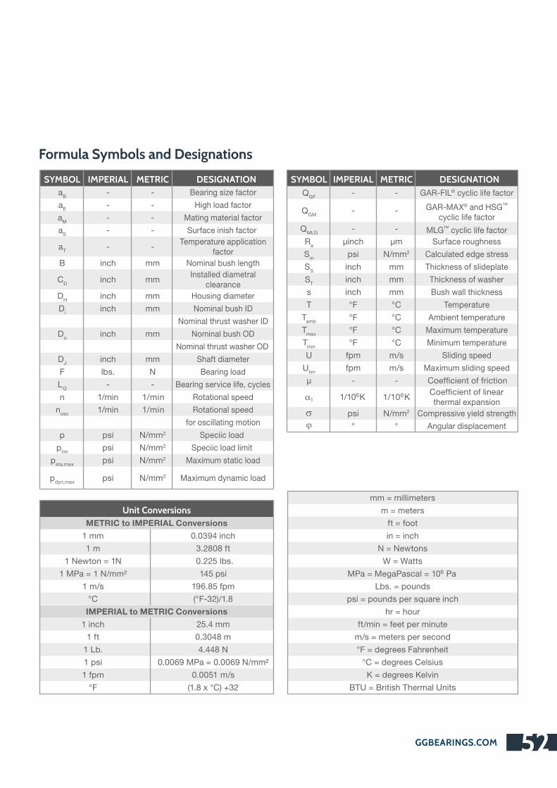
GGBEARINGS.COM 52
SYMBOL IMPERIAL METRIC DESIGNATION
aB
- -
aE
- -
aM
- -
aS
- -
aT
- -
B inch mm
CD
inch mm
DH
inch mm
Di
inch mm
Do
inch mm
DJ
inch mm
F lbs. N
LQ
- - Bearing service life, cycles
n 1/min 1/min
nosc
1/min 1/min
p psi N/mm2
plim
psi N/mm2
psta,max
psi N/mm2
pdyn,max
psi N/mm2
Bearing size factor
High load factor
Mating material factor
Surface inish factor
Temperature application factor
Nominal bush length
Installed diametral clearance
Housing diameter
Nominal bush ID
Nominal thrust washer ID
Nominal bush OD
Nominal thrust washer OD
Shaft diameter
Bearing load
Rotational speed
Rotational speed
for oscillating motion
Speciic load
Speciic load limit
Maximum static load
Maximum dynamic load
SYMBOL IMPERIAL METRIC DESIGNATION
QGF
- - GAR-FIL® cyclic life factor
QGM
- - GAR-MAX® and HSG™ cyclic life factor
QMLG
- - MLG™ cyclic life factor
Ra
µinch µm Surface roughness
Sm
psi N/mm2 Calculated edge stress
SS
inch mm Thickness of slideplate
ST
inch mm Thickness of washer
s inch mm Bush wall thickness
T °F °C Temperature
Tamb
°F °C Ambient temperature
Tmax
°F °C Maximum temperature
Tmin
°F °C Minimum temperature
U fpm m/s Sliding speed
Ulim
fpm m/s Maximum sliding speed
µ - -
61/10 K 61/10 K
thermal expansion
psi N/mm2 Compressive yield strength
° ° Angular displacement
Unit Conversions
METRIC to IMPERIAL Conversions
1 mm
1 m
1 Newton = 1N
1 MPa = 1 N/mm²
1 m/s
°C
IMPERIAL to METRIC Conversions
1 inch
1 ft
1 Lb.
1 psi
1 fpm
°F
0.0394 inch
3.2808 ft
0.225 lbs.
145 psi
196.85 fpm
(°F-32)/1.8
25.4 mm
0.3048 m
4.448 N
0.0069 MPa = 0.0069 N/mm²
0.0051 m/s
(1.8 x °C) +32
Formula Symbols and Designations
mm = millimeters
m = meters
ft = foot
in = inch
N = Newtons
W = Watts6MPa = MegaPascal = 10 Pa
Lbs. = pounds
psi = pounds per square inch
hr = hour
ft/min = feet per minute
m/s = meters per second
°F = degrees Fahrenheit
°C = degrees Celsius
K = degrees Kelvin
BTU = British Thermal Units
Coefficient of friction
Coefficient of linear
s
a1
j

Metal Polymerggbearings.com/en/category-product/metal-polymerWe manufacture metal-backed, PTFE-based and thermoplastic metal-polymer bearings that share a common structure consisting of a porous bronze sinter bonded into a metal backing. This bronze sinter layer is impregnated and overlaid with the filled PTFE or thermoplastic extruded tape liner.
The metal backing provides mechanical strength, while the bronze sinter layer provides a strong mechanical bond between the backing and the antifriction bearing lining. This construction promotes dimensional stability, improves thermal conductivity and offers exceptionally low friction. These materials are generally for use in marginally lubricated applications.
Solid Polymerggbearings.com/en/category-product/solid-polymerOur injection-molded solid polymer bearings provide excellent wear resistance and low friction in both dry and lubricated operating conditions over a wide range of applications.
®The EP Series of solid polymer materials exhibits excellent dimensional stability, low coefficients of friction and thermal expansion, high compressive strength and creep resistance and good thermal conductivity.
TM We also manufacture acetal-based KA Glacetal thrust washers for light-duty applications, TM ®Multilube bearings that contain lubricants dispersed in the material and FLASH-CLICK
bearings for simply manual or automated installation without a pilot or assembly tools.
Bushing Blocks and Thrust Platesggbearings.com/en/category-product/bushing-blocks-and-thrust-platesGGB’s high precision bushing blocks and thrust plates are made from our proprietary aluminum alloys and provide good friction and wear resistance. They can be supplied with or without pre-installed GGB metal-polymer cylindrical bearings.
Metal and Bimetal Bearingsggbearings.com/en/category-product/metals-and-bimetalsWe have a broad range of monometallic, bimetallic and sintered bronze bearings including our DB bearings, which are ideal for industrial applications on both land and underwater. Our range of impregnated solid bronze bearings is intended for use in maintenance-free operations, under moderately high speeds and low loads. Designed for lubricated conditions, our mono- and bimetallic bearings are suitable for use in a wide range of operating conditions.
Assembliesggbearings.com/en/category-product/assembliesWe offer a variety of specialized housings and assemblies to complement our complete line of
TM TM TMplain bearing solutions. UNI , MINI and EXALIGN self-aligning bearing housings are designed to be used with our range of metal-polymer bearings.
Whatever your application requires, GGB offers the solution with its wide range of bearing products:
GGBEARINGS.COM53
8.7 Other GGB Bearing Products
®EP 22
®EP 43
®DP4
®DX
®SICAL 3
EXALIGN™
DB™
®GGB-CSM
an EnPro Industries company
The Global Leader
in High Performance Bearing Solutions

Visit us on the internet:
www.ggbearings.com
GGBEARINGS.COM 54
© 2015 GGB. All rights reserved.
® ® TM TM TM TM ® TM TM TMGGB , GAR-MAX , GAR-FIL , HSG , MLG , HPM , HPMB , HPF , Multifil and SBC
are registered trademarks or trademarks, as the case may be, of GGB and its affiliates.
GGB gives an assurance that the products described in this document have no manufacturing errors or
material deficiencies.
The details set out in this document are registered to assist in assessing the material’s suitability for the
intended use. They have been developed from our own investigations as well as from generally accessible
publications. They do not represent any assurance for the properties themselves.
Unless expressly declared in writing, GGB gives no warranty that the products described are suited to any
particular purpose or specific operating circumstances. GGB accepts no liability for any losses, damages or
costs however they may arise through direct or indirect use of these products.
GGB’s sales and delivery terms and conditions, included as an integral part of quotations, stock and price lists,
apply absolutely to all business conducted by GGB. Copies can be made available on request.
Products are subject to continual development. GGB retains the right to make specification amendments or
improvements to the technical data without prior announcement.
Edition 2015 (This edition replaces earlier editions which hereby lose their validity).
GGB is committed to adhering to all U.S., European and international standards and regulations with regard
to lead content. We have established internal processes that monitor any changes to existing standards and
regulations, and we work collaboratively with customers and distributors to ensure that all requirements are
strictly followed. This includes RoHS and REACH guidelines.
GGB makes it a top priority to operate in an environmentally conscious and safe manner. We follow numerous
industry best practices, and are committed to meeting or exceeding a variety of internationally recognized
standards for emissions control and workplace safety.
Each of our global locations has management systems in place that adhere to ISO TS 16949, ISO 9001,
ISO 14001, ISO 50001 and OHSAS 18001 quality regulations.
All of our certificates can be found here: http://www.ggbearings.com/en/company/certificates. A detailed
explanation of our commitment to REACH and RoHS directives can be found at www.ggbearings.com/en/
company/quality-and-environment.
Statement Regarding Lead Content in GGB Products & EU Directive Compliance
8.8 Product Information

GGBEARINGS.COM55
9.0 Your Notes
an EnPro Industries company
The Global Leader
in High Performance Bearing Solutions

GGBEARINGS.COM 56

an EnPro Industries company
The Global Leader in High Performance Bearing Solutions
HB300ENG08-15HN
GGB Heilbronn GmbH
Postfach 18 62 D-74008 Heilbronn•
Ochsenbrunnenstraße 9 D-74078 Heilbronn•
Industriegebiet Böllinger Höfe
Tel. +49 7131 269 0 Fax +49 7131 269 500•
eMail: [email protected] www.ggbearings.de•