Embed Size (px)
Citation preview
FIBERGLASS INNOVATION
ENERGY EFFICIENTLOW COSTFAST INSTALLATION
CASCADIA CLIP®
FIBERGLASS THERMAL SPACER
CASCADIACLIP.COM
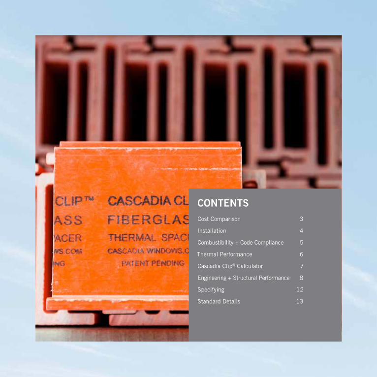
CONTENTS Cost Comparison 3
Installation 4
Combustibility + Code Compliance 5
Thermal Performance 6
Cascadia Clip® Calculator 7
Engineering + Structural Performance 8
Specifying 12
Standard Details 13
1
WH
Y FIBE
RG
LAS
S?
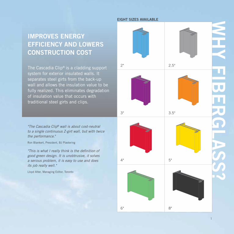
IMPROVES ENERGY EFFICIENCY AND LOWERS CONSTRUCTION COST
The Cascadia Clip® is a cladding support system for exterior insulated walls. It separates steel girts from the back-up wall and allows the insulation value to be fully realized. This eliminates degradation of insulation value that occurs with traditional steel girts and clips.
"The Cascadia Clip® wall is about cost-neutral to a single continuous Z-girt wall, but with twice the performance."
Ron Blankert, President, BJ Plastering
"This is what I really think is the definition of good green design. It is unobtrusive, it solves a serious problem, it is easy to use and does its job really well."
Lloyd Alter, Managing Editor, Toronto
3"
2"
6"
4"
3.5"
2.5"
5"
8"
EIGHT SIZES AVAILABLE
2
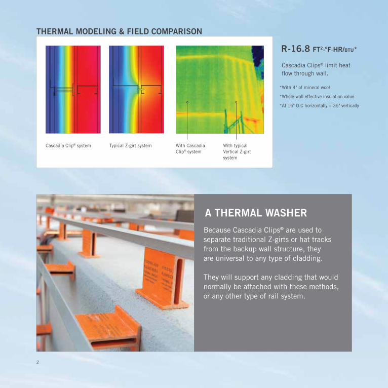
THERMAL MODELING & FIELD COMPARISON
*With 4" of mineral wool
*Whole-wall effective insulation value
*At 16" O.C horizontally + 36" vertically
R-16.8 FT2·°F·HR/btu*
With typical Vertical Z-girt system
With Cascadia Clip® system
Typical Z-girt systemCascadia Clip® system
Cascadia Clips® limit heat flow through wall.
A THERMAL WASHER
Because Cascadia Clips® are used to separate traditional Z-girts or hat tracks from the backup wall structure, they are universal to any type of cladding.
They will support any cladding that would normally be attached with these methods, or any other type of rail system.
3
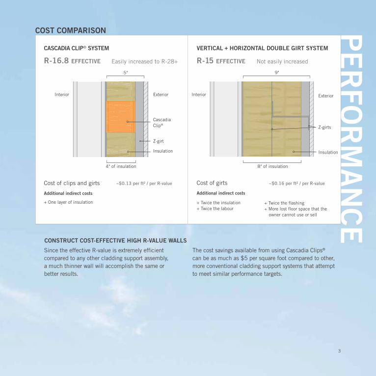
CONSTRUCT COST-EFFECTIVE HIGH R-VALUE WALLS
Since the effective R-value is extremely efficient compared to any other cladding support assembly, a much thinner wall will accomplish the same or better results.
The cost savings available from using Cascadia Clips® can be as much as $5 per square foot compared to other, more conventional cladding support systems that attempt to meet similar performance targets.
PE
RFO
RM
AN
CE
COST COMPARISON
VERTICAL + HORIZONTAL DOUBLE GIRT SYSTEM
Easily increased to R-28+ Not easily increased
Interior Interior
R-16.8 EFFECTIVE R-15 EFFECTIVE
9"5"
+ Twice the flashing + More lost floor space that the owner cannot use or sell
~$0.13 per ft² / per R-value ~$0.16 per ft² / per R-value
4" of insulation 8" of insulation
Cost of clips and girts
Additional indirect costs
+ One layer of insulation
Cost of girts
Additional indirect costs
+ Twice the insulation + Twice the labour
CASCADIA CLIP® SYSTEM
Insulation
Z-girts
Exterior
Z-girt
Insulation
Exterior
Cascadia Clip®
4
INS
TALL
ATIO
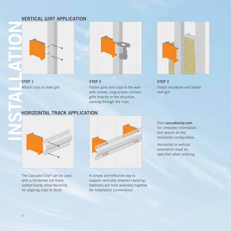
NVERTICAL GIRT APPLICATION
STEP 2STEP 1
Attach clips to steel girt Fasten girts and clips to the wall with screws; long screws connect girts directly to the structure, passing through the clips
STEP 3
Install insulation and fasten next girt
HORIZONTAL TRACK APPLICATION
A simple and effective way to support vertically oriented cladding; fasteners will hold assembly together for installation convenience
The Cascadia Clip® can be used with a horizontal hat-track; slotted tracks allow flexibility for aligning clips to studs
Visit cascadiaclip.com for complete information and details on the horizontal configuration
Horizontal or vertical orientation must be specified when ordering
5
CO
MB
US
TIBILITY
CANADA
THE CASCADIA CLIP® IS FULLY CODE-COMPLIANT FOR FIRE PERFORMANCE IN BOTH CANADA AND THE USA FOR EVERY TYPE OF WALL ASSEMBLY.1. The Clips are intermittent, both vertically and horizontally, and almost completely covered by non-
combustible mineral wool. Because of this, they do not alter the wall's fire protection in any way – for better or for worse.
2. Fire does not damage the Clips' ability to hold the cladding in place, because cladding is attached to steel Z-girts which are attached directly to the backup wall with screws passing completely through the clip.
The fiberglass clips are not a structural connection for the cladding: the structural connection of cladding to backup wall is done via steel girts and screws.
While fiberglass is combustible, the clip functions within non-combustible wall assemblies as a minor combustible component, in accordance with Article 3.1.5.2 of the Model National Building Code.
The clip is enclosed within the non-combustible insulation and the fasteners attach the cladding directly to the structure. Fire protection and building code professionals support the clip as a minor combustible component, in compliance with the building code.
The Building and Safety Standards Branch of the BC Ministry of Energy and Mines confirmed that the Cascadia Clip® is a minor combustible component, acceptable for use in non-combustible construction.
The Cascadia Clip® has been approved through IAPMO for a Uniform Evaluation Service report, evaluating the Clip for use in projects across the USA, in all types of construction, including non-combustible wall assemblies. The IAPMO UES report evaluates the Clip for the 2012 and 2015 international Building Code, ensuring that the clips have met the most rigorous standards and are in full compliance. Using comprehensive fire-testing data, including a successful NFPA 285 report with combustible cladding, the evaluation approves the clip for use in non-combustible wall assemblies.
It also includes analysis and approval of durability, structural capacity, and more. Cascadia Clips® are the only thermally improved cladding support system with a code evaluation. Please contact us or visit our website for more information or a copy of this report!
USA
6
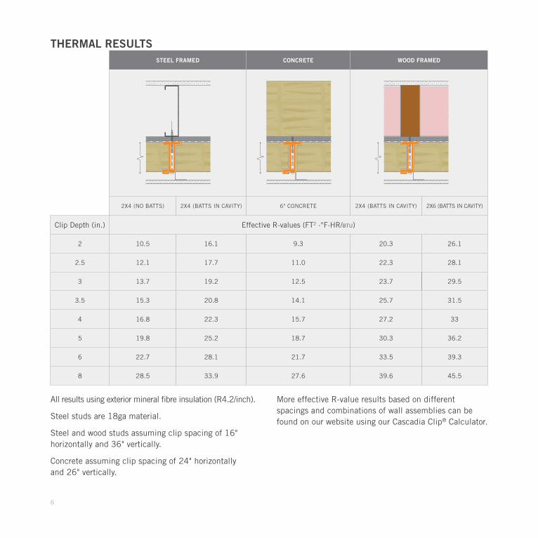
STEEL FRAMED CONCRETE WOOD FRAMED
2X4 (NO BATTS) 2X4 (BATTS IN CAVITY) 6" CONCRETE 2X4 (BATTS IN CAVITY) 2X6 (BATTS IN CAVITY)
Clip Depth (in.) Effective R-values (FT2 ·°F·HR/btu)
2 10.5 16.1 9.3 20.3 26.1
2.5 12.1 17.7 11.0 22.3 28.1
3 13.7 19.2 12.5 23.7 29.5
3.5 15.3 20.8 14.1 25.7 31.5
4 16.8 22.3 15.7 27.2 33
5 19.8 25.2 18.7 30.3 36.2
6 22.7 28.1 21.7 33.5 39.3
8 28.5 33.9 27.6 39.6 45.5
THERMAL RESULTS
All results using exterior mineral fibre insulation (R4.2/inch).
Steel studs are 18ga material.
Steel and wood studs assuming clip spacing of 16" horizontally and 36" vertically.
Concrete assuming clip spacing of 24" horizontally and 26" vertically.
More effective R-value results based on different spacings and combinations of wall assemblies can be found on our website using our Cascadia Clip® Calculator.
7
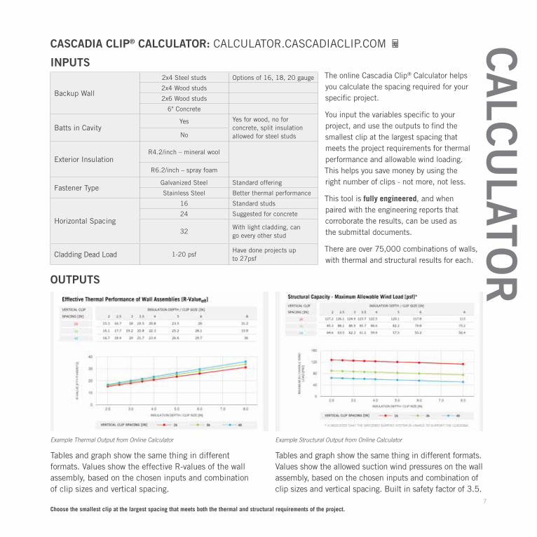
INPUTS
OUTPUTS
CASCADIA CLIP® CALCULATOR: CALCULATOR.CASCADIACLIP.COM
The online Cascadia Clip® Calculator helps you calculate the spacing required for your specific project.
You input the variables specific to your project, and use the outputs to find the smallest clip at the largest spacing that meets the project requirements for thermal performance and allowable wind loading. This helps you save money by using the right number of clips - not more, not less.
This tool is fully engineered, and when paired with the engineering reports that corroborate the results, can be used as the submittal documents.
There are over 75,000 combinations of walls, with thermal and structural results for each.
Backup Wall
2x4 Steel studs Options of 16, 18, 20 gauge
2x4 Wood studs
2x6 Wood studs
6" Concrete
Batts in CavityYes Yes for wood, no for
concrete, split insulation allowed for steel studsNo
Exterior InsulationR4.2/inch – mineral wool
R6.2/inch – spray foam
Fastener TypeGalvanized Steel Standard offering
Stainless Steel Better thermal performance
Horizontal Spacing
16 Standard studs
24 Suggested for concrete
32With light cladding, can go every other stud
Cladding Dead Load 1-20 psfHave done projects up to 27psf
Choose the smallest clip at the largest spacing that meets both the thermal and structural requirements of the project.
Tables and graph show the same thing in different formats. Values show the effective R-values of the wall assembly, based on the chosen inputs and combination of clip sizes and vertical spacing.
Example Thermal Output from Online Calculator
Tables and graph show the same thing in different formats. Values show the allowed suction wind pressures on the wall assembly, based on the chosen inputs and combination of clip sizes and vertical spacing. Built in safety factor of 3.5.
Example Structural Output from Online Calculator
CA
LCU
LATOR
8
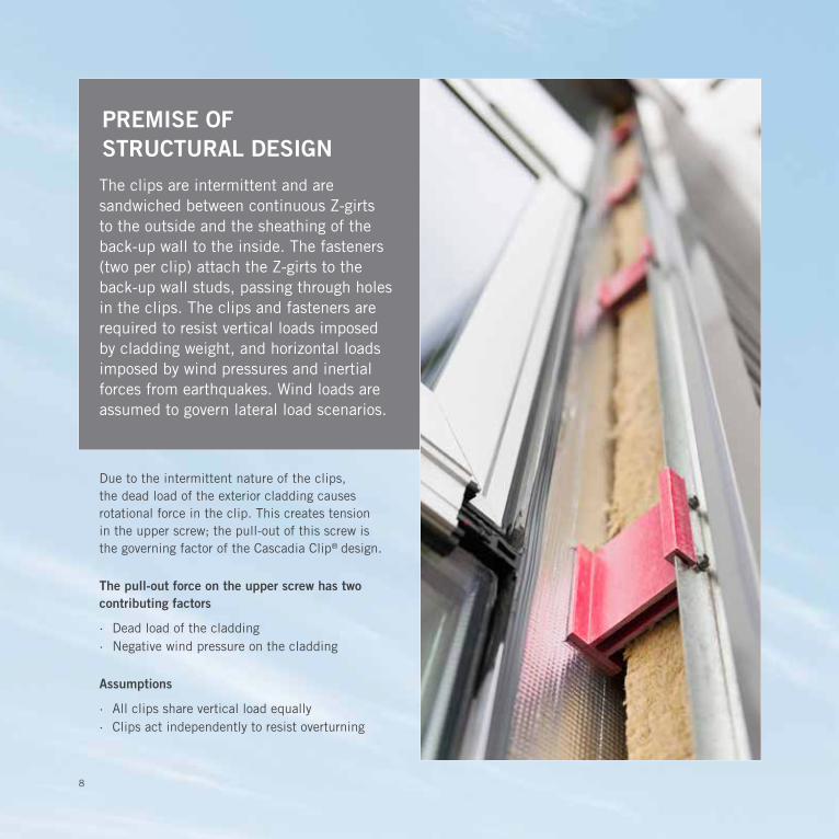
Due to the intermittent nature of the clips, the dead load of the exterior cladding causes rotational force in the clip. This creates tension in the upper screw; the pull-out of this screw is the governing factor of the Cascadia Clip® design.
The pull-out force on the upper screw has two contributing factors
· Dead load of the cladding · Negative wind pressure on the cladding
Assumptions
· All clips share vertical load equally · Clips act independently to resist overturning
PREMISE OF STRUCTURAL DESIGN
The clips are intermittent and are sandwiched between continuous Z-girts to the outside and the sheathing of the back-up wall to the inside. The fasteners (two per clip) attach the Z-girts to the back-up wall studs, passing through holes in the clips. The clips and fasteners are required to resist vertical loads imposed by cladding weight, and horizontal loads imposed by wind pressures and inertial forces from earthquakes. Wind loads are assumed to govern lateral load scenarios.

9
TECHNICAL DETAILSThe design information provided in this brochure has been prepared based on a review of industry available screw pull-out and shear load test data, with resultant factors of safety in the connection design ranging from 3 to 4. The specific design curves included in the brochure are based on a FS of 3.5 utilizing the fasteners identified in the above chart as ‘Recommended Fasteners’ for each substrate type. It is important to note that in the design curves for applications in 20 ga and 18 ga steel framing, Leland’s ¼" Master Driller screw with no.2 mini drill point is used, and provides greater capacity than common no.3 drill points. The use of mini drill point screws provides for reasonable ease of installation, while maintaining significantly higher pull-out resistances than no.3 drill points in light gauge steel framing.
The design of screw fastened connections is a task normally completed or reviewed by a structural engineer. The online Cascadia Clip® Calculator is a fully engineered design tool, complete with stamped engineering reports, to illustrate acceptable design application of the Cascadia Clips® under numerous building and environmental conditions. This calculator can be used for engineered submittal documents of the wall assembly, as long as the wall configurations are upheld.
The Cascadia Clip® is a suitable substrate for a number of cladding systems, including stucco. Stucco is inherently prone to cracking, and Cascadia assumes no responsibility whatsoever for any cracking of a stucco application.
STEEL STUD SUBSTRATE – RECOMMENDED FASTENER: LELAND INDUSTRIES – ¼ X 14 MASTER DRILLER NO.2 MINI DRILL POINT, DT 2000 COATED
For 20 gauge studsTALLOW 623 N 140 lb Leland Industries – Manufacturer's Testing
VALLOW 602 N 135 lb Deitrich
For 18 gauge studsTALLOW 877 N 197 lb Leland Industries – Manufacturer's Testing
VALLOW 892 N 201 lb Deitrich
WOOD STUD SUBSTRATE – RECOMMENDED FASTENER: LELAND INDUSTRIES – ¼ X 10 MASTER GRIPPER, DT 2000 COATED
Wood studs + plywood sheathingTALLOW 841 N 189 lb Values from Leland Master Gripper 14 x 10 with 1" effective
penetration into Douglas FirVALLOW 560 N 126 lb
CONCRETE/CMU SUBSTRATE – RECOMMENDED FASTENER: LELAND INDUSTRIES – #14 X 15 CONCRETE SCREW, DT 2000 COATED
4000 psi Concrete – 1.5" embedment
TALLOW 1645 N 370 lbIntertek Testing of Leland Industries 14-15 concrete screws; predrilled holes at 3⁄16" diameter
Hollow Concrete Masonry Units – 1.0" embedment
TALLOW 843 N 189 lbIntertek Testing of Leland Industries 14-15 concrete screws; predrilled holes at 3⁄16" diameter
ALLOWABLE FASTENER LOADS (FACTOR OF SAFETY: 3.5)
Sheathing thickness 12.7 mm 0.5 in
Vertical girt depth 25.4 mm 1 in
Cladding thickness 19.05 mm 0.75 in
Cascadia Clip® size
Depth Varies Varies
Length 101.6 mm 4.0 in
Screw edge distance 12.7 mm 0.5 in
Screw spacing 76.2 mm 3.0 in
SCREW FASTENER DESIGN PARAMETERS EN
GIN
EE
RIN
G
Assumptions
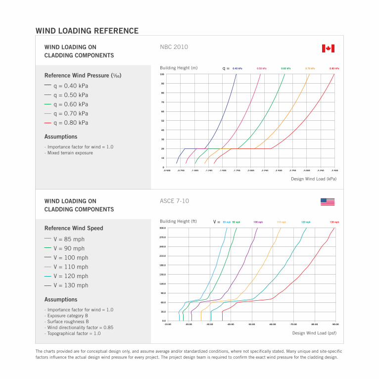
· Importance factor for wind = 1.0 · Mixed terrain exposure
Reference Wind Pressure (1⁄50)
Reference Wind Speed
Building Height (m)
Design Wind Load (kPa)
NBC 2010WIND LOADING ON CLADDING COMPONENTS
WIND LOADING ON CLADDING COMPONENTS
ASCE 7-10
Design Wind Load (psf)
Building Height (ft)
Assumptions
· Importance factor for wind = 1.0 · Exposure category B · Surface roughness B · Wind directionality factor = 0.85 · Topographical factor = 1.0
WIND LOADING REFERENCE
0.80 kPa0.70 kPa0.60 kPa0.50 kPa0.40 kPaq =100
90
80
70
60
50
40
30
20
10
0-0.500 -0.750 -1.000 -1.250 -1.500 -1.750 -2.000 -2.250 -2.500 -2.750 -3.000 -3.250 -3.500
130 mph120 mph110 mph100 mph90 mph85 mphV =300.0
270.0
240.0
210.0
180.0
150.0
120.0
90.0
60.0
30.0
0.0
-20.00-10.00 -30.00 -40.00 -50.00 -60.00 -70.00 -80.00 -90.00
V = 85 mph
V = 90 mph
V = 100 mph
V = 110 mph
V = 120 mph
V = 130 mph
q = 0.40 kPa
q = 0.50 kPa
q = 0.60 kPa
q = 0.70 kPa
q = 0.80 kPa
The charts provided are for conceptual design only, and assume average and/or standardized conditions, where not specifically stated. Many unique and site-specific factors influence the actual design wind pressure for every project. The project design team is required to confirm the exact wind pressure for the cladding design.
11
80
100
120
140
60
40
20
3.8
4.75
5.7
6.65
2.85
1.9
0.95
0 0
20181614121086420
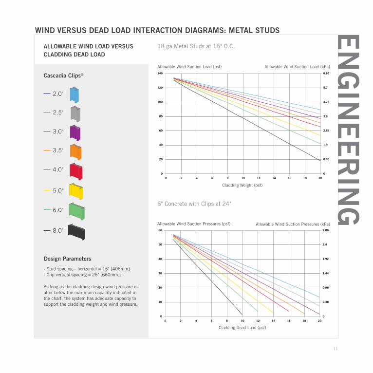
ALLOWABLE WIND LOAD VERSUS CLADDING DEAD LOAD
As long as the cladding design wind pressure is at or below the maximum capacity indicated in the chart, the system has adequate capacity to support the cladding weight and wind pressure.
WIND VERSUS DEAD LOAD INTERACTION DIAGRAMS: METAL STUDS
Design Parameters
· Stud spacing – horizontal = 16" [406mm] · Clip vertical spacing = 26" [660mm]z
Allowable Wind Suction Pressures (psf)
Cladding Weight (psf)
Cladding Dead Load (psf)
Allowable Wind Suction Pressures (kPa)
Allowable Wind Suction Load (psf)
18 ga Metal Studs at 16" O.C.
6" Concrete with Clips at 24"
Cascadia Clips®
2.5"
2.0"
3.0"
5.0"
3.5"
6.0"
8.0"
40
50
60
30
20
10
1.92
2.4
2.88
1.44
0.96
0.48
0 0
20181614121086420
EN
GIN
EE
RIN
G
4.0"
Allowable Wind Suction Load (kPa)
12
INTERNATIONAL LIVING FUTURE INSTITUTESM declareproducts.com
SM
Cascadia Clip Fiberglass Pultrusion: Glass Fiber (La Crosse, WI); Polyester Resin: Base Resin - Polyester (LaCrosse, WI), Calcium Carbonate Filler (LaCrosse, WI), Polystyrene, Release Agent*, Pigment*
*LBC Temp Exception I10-E4 Proprietary Ingredients <1%
Cascadia Clip®Cascadia Windows Ltd.Final Assembly: Langley, BC, CanadaLife Expectancy: 200+ Years End of Life Options: Salvageable/Reusable in its Entirety, Landfi ll
Ingredients:
MANUFACTURER RESPONSIBLE FOR LABEL ACCURACY
Living Building Challenge Criteria:
CAW-0003 04/01/2016VOC Content: N/A VOC Emissions: N/ADeclaration Status LBC Red List Free LBC Compliant Declared
DECLARE LABEL
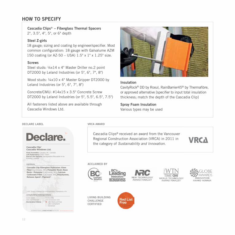
HOW TO SPECIFY
Cascadia Clips® – Fiberglass Thermal Spacers 2", 3.5", 4", 5", or 6" depth
Steel Z-girts 18 gauge; sizing and coating by engineer/specifier. Most common configuration: 18 gauge with Galvalume AZM 150 coating (or AZ-50 – USA) 1.5" x 1" x 1.25" size.
Screws Steel studs: ¼x14 x 4" Master Driller no.2 point DT2000 by Leland Industries (or 5", 6", 7", 8")
Wood studs: ¼x10 x 4" Master Gripper DT2000 by Leland Industries (or 5", 6", 7", 8")
Concrete/CMU: #14x15 x 3.5" Concrete Screw DT2000 by Leland Industries (or 5", 5.5", 6.5", 7.5")
All fasteners listed above are available through Cascadia Windows Ltd.
Insulation CavityRock® DD by Roxul, RainBarrier45® by Thermafibre, or approved alternative [specifier to input total insulation thickness; match the depth of the Cascadia Clip]
Spray Foam Insulation Various types may be used
VRCA AWARD
ACCLAIMED BY
Cascadia Clips® received an award from the Vancouver Regional Construction Association (VRCA) in 2011 in the category of Sustainability and Innovation.
LIVING BUILDING CHALLENGE CERTIFIED
13
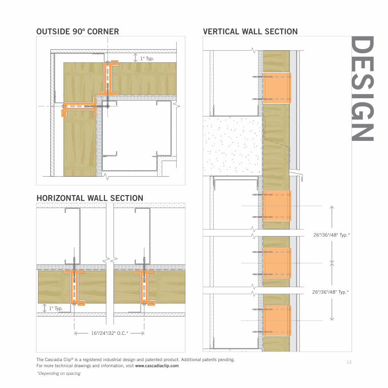
DE
SIG
NOUTSIDE 90º CORNER
HORIZONTAL WALL SECTION
VERTICAL WALL SECTION
26"/36"/48" Typ.*
26"/36"/48" Typ.*
1" Typ.
1" Typ.
The Cascadia Clip® is a registered industrial design and patented product. Additional patents pending. For more technical drawings and information, visit www.cascadiaclip.com
16"/24"/32" O.C.*
*Depending on spacing
FOR FURTHER INFORMATION ON THE CASCADIA CLIP®
CALL 604 857 4600 EMAIL [email protected]
CONTACT A TECHNICAL SALES REP IN YOUR AREA BY VISITING CASCADIACLIP.COM SEE THE ‘CONTACT US’ PAGE.
CASCADIA WINDOWS LTD. LANGLEY, BRITISH COLUMBIA 604 857 4600
CASCADIACLIP.COM