Embed Size (px)
Citation preview

I S S U E 3 4 4 J U LY 3 0 , 2 0 1 3
Apogee Components, Inc. — Your Source For Rocket Supplies That Will Take You To The “Peak-of-Flight”3355 Fillmore Ridge Heights
Colorado Springs, Colorado 80907-9024 USAwww.ApogeeRockets.com e-mail: [email protected]
Phone: 719-535-9335 Fax: 719-534-9050
Fiberglass Parts by “Lost Foam” Technique
In This Issue
Cover Photo:Tim’s daughter prepares to launch her Saturn IB Kit for Scale Competition at NARAM 2013. Get your own Saturn IB at http://www.apogeerockets.com/Rocket_Kits/Skill_Level_5_Kits/Saturn_1B_1_70th_Scale
Page 2 I S S U E 3 4 4 J U LY 3 0 , 2 0 1 3
You can subscribe to receive this e-zine FREE at the Apogee Components web site (www.ApogeeRockets.com), or by sending an e-mail to: [email protected] with “SUB-SCRIBE” as the subject line of the message.
About this Newsletter Newsletter Staff
Writer: Tim Van MilliganLayout / Cover Artist: Erin CardProofreader: Michelle Mason
By Daniel Cavender
Continued on page 3
When I started building more unique looking model rockets, I needed to find ways to build those uniquely shaped parts like nose cones, airframes, fins, and even wings and fairings. I couldn’t use an off-the-shelf ogive nose cone for most of these builds especially if the airframe was not a cylinder anymore. Now there are several techniques for building these unique parts, so you have to consider a few things to select the most appropriate technique for your intended application. For example, do you need to make more than one? If so, you need to consider making a reusable mold. If you only want one, then you can use a technique called “Lost Foam”.
The lost foam technique is a one-pop-shot method where you first build an expendable foam mold of the part that you wish to layup your fiberglass part on. You then layup your fiberglass part on the mold. After the part is cured, you either dissolve the foam chemically or remove it mechanically to retrieve your finished part. Styrofoam and other “open cell” foams can be dissolved with acetone. The dissolved foam can then be cleaned out of the part. Urethane and other “closed cell” foams are chemically resistant and must be removed mechanically, which is to say that you need to get some tools and start chipping it away.
Internal molds, or plugs, are molds where the composite materials are laid up over the top. They are useful for making nose cones, transitions, and fairings. There is something important to consider when building an internal mold. You want your finished part to match the outer mold line (OML) of your rocket, so the internal mold must be shaped a bit smaller so that when you build up the fiberglass plys on the mold, the final plys match the outer profile of the rest of the rocket. You may also want the inner mold line (IML) of the finished part to accept a coupler so the internal mold should match the coupler’s outer diameter (OD). Figure 1 helps illustrate how to build a lost foam part using an internal mold. External molds or reverse molds, are molds where the composite materials are laid up inside the mold. The OML of the part is formed on the mold rather than built up from it. For the most part, reverse molds are made of one or more pieces and are intended to reproduce multiple parts and are not as common with lost foam technique.
Both open and closed cell foams have their merits. Open
cell foams like Styrofoam are widely available in many different shapes and sizes. Their densities vary slightly and they can be easily formed with a variety of tools. They are not castable without special processing, and they are soft foams, so some advanced composite layup techniques like vacuum bagging can deform the foam mold. Closed cell foams are usually expanding two-part resin and catalyst formulas that can be poured into forms. They expand to fill volumes, but can be messy. The process is exothermic
Fiberglass Parts by “Lost Foam” Technique
Figure 1: Overview of creating the fiberglass nose cone with a plug mold
Page 3I S S U E 3 4 4 J U LY 3 0 , 2 0 1 3
Fiberglass Parts by “Lost Foam” Technique
Continued from page 2
(chemical reaction releases heat) so large mixes can get quite hot. These foam formulas can be very light or very dense. Light foams are easy to form but are soft. High density foams are structurally rigid but are harder to form and harder to chip out of parts later. I typically use medium density closed cell foams for nose cone molds and other parts that I turn on a lathe and use extruded Styrofoam for almost everything else. Both methods present unique safety hazards, so for whichever method you use wear appropriate personal protective equipment (PPE) such as safety glasses, gloves, masks, etc. and adequately ventilate your workshop.
I used the lost foam technique to build a nose cone and an engine bell for my 4.5 inch Pegasus XL rocket project. The final outer diameter of the nose cone’s OML needed to be 4.45 inches. I used 6.0 oz/yd weight plain fiberglass which has a thickness of 0.009 inches. I wanted the nose cone to be 6 plys thick. That calculates to a wall thickness of 0.053 inches not accounting for the resin. So, that meant that the diameter of my plug mold needed to be about 4.33 inches.
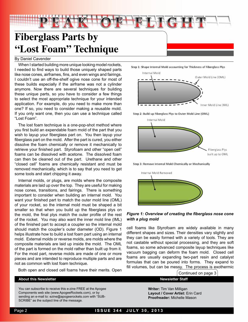
Building a Lost Foam Nose ConeI elected to use 8 pound density 1:1 mixture urethane foam
for the nose cone mold so that I could cast an aluminum bar into the foam to chuck it in my lathe to turn the foam down to the final form. I had a segment of 5 inch fiberglass airframe that would make a good casting pot. I wrapped a
layer of Dura-Lar clear polyester vinyl on the inside of the 5 inch airframe so that the foam would not bond to the tube. I calculated the amount of urethane foam needed to fill the tube. The urethane foam expands 5 times its initial liquid volume. The tube was 12 inches tall, so it had a volume of 0.14 cubic feet. At a density of 8 pounds per cubic foot, I needed about 1.0 pounds of foam. I mixed the foam and poured it into the tube, and as the foam was rising, I set the aluminum rod into the foam aligning it with the tube’s axis. The foam was fully cured in 45 minutes, and I easily pulled the foam out of the tube thanks to the Dura-Lar.
Continued on page 4
ww
w.A
pog
eeRock
ets.comYour Source For Everything
Rock
etry
• Reusable Rocket Motors Save Money• Holds Aerotech’s Reload Propellant• Sizes: 24mm To 98mm Diameter• Power Range: E Through N• Cases For Any Project• Rouse-Tech Quality• Affordable!
• Reusable Rocket Motors Save Money• Holds Aerotech’s Reload Propellant• Sizes: 24mm To 98mm Diameter• Power Range: E Through N• Cases For Any Project• Rouse-Tech Quality• Affordable!
High-Power Reload CasingsHigh-Power Reload Casings
Figure 2: Poured foam nose cone mold base
Page 4 I S S U E 3 4 4 J U LY 3 0 , 2 0 1 3
Continued from page 3
Continued on page 5
We’re Paying CashFor Great Articles for This Newsletter
Are you a writer looking for some serious pocket change? We’re paying up to $350 for good how-to articles for this newsletter. If you’re interested, see our submission guidelines on the Apogee web site.
www.ApogeeRockets.com/Newsletter/Newsletter_Guidelines
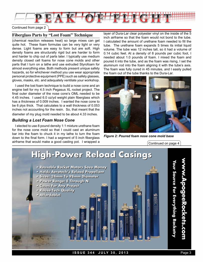
I chucked the aluminum rod in the lathe and began to file and sand the foam plug down to my required IML. Most people don’t have a lathe at home, but you can achieve some good results with a drill press and even a hand held drill mounted to a work bench with clamps. You should not wear hanging jewelry around your hands or neck, loose fitting, or baggy clothes when operating rotary tools. Be sure to pull back long hair. This part of the job is a respiratory hazard so wear safety glasses, a dust mask, and then clean the area after you are done. I also duck-taped my shop-vac hose to the tooling post so that the hose end was near the foam plug and could catch the foam dust before it spread. I made a template to help form the parabolic shaped of the nose cone by printing a 1:1 scale drawing of the CAD model, gluing it to a cardboard backing, and cutting out the IML curve on the template with a hobby knife. I checked the dimensions often with a set of calipers. Once I achieved my required IML, I lightly sanded the surface with a high grit sand paper then wiped the plug with a damp shop rag to remove much of the loose particulate. That is about all of the mold preparation required. Now, let’s move on to the layup preparation.
Fiberglass LayupLike most fiberglass jobs, there is a good deal of work
involved in the preparation alone. I wanted to layup 6 plys of
6 ounce plain weave fiberglass on the plug to build up the nose cone. The plain weave drapes very well over most forms so I planned to make each ply from two overlapping panels that have a bullnose front to match the contour of the nose cone when wetted out any laid flat on the plug. The plug had an OD of 4.35”, which translates to a circumference of roughly 13.75 inches. Each of the 12 panels will be 7.25 inches wide and 10 inches long. I also cut a 14 inch wide and 12 inch long piece of peel-ply to lay over the layup once it was finished. Each panel would cover just over half of the mold. Each edge of the panel would overlap the previous.
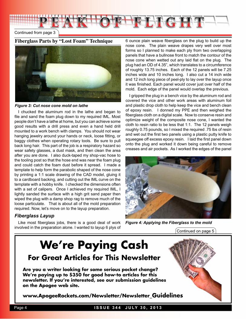
I gripped the plug in a bench vice by the aluminum rod and covered the vice and other work areas with aluminum foil and plastic drop cloth to help keep the vice and bench clean of epoxy resin. I donned my PPE and then weighed the fiberglass cloth on a digital scale. Now to conserve resin and optimize weight of the composite nose cone, I wanted the cloth to resin ratio to be less that 1:1. The 12 panels weigh roughly 0.75 pounds, so I mixed the required .75 lbs of resin and wet out the first two panels using a plastic putty knife to squeegee off excess epoxy resin. I laid the first panel down onto the plug and worked it down being careful to remove creases and air pockets. As I worked the edges of the panel
Fiberglass Parts by “Lost Foam” Technique
Figure 3: Cut nose cone mold on lathe
Figure 4: Applying the Fiberglass to the mold
Page 5I S S U E 3 4 4 J U LY 3 0 , 2 0 1 3
Continued from page 4
Continued on page 6
Experienced HPR Builders Use Thrust Plates
• Eliminates Shear Forces on Centering Rings• Mates with AeroPack’s Flanged Engine Retainers• Fits Standard HPR Tubes, Blue Tubes, and Fiberglass Tubes• Made from Aircraft Grade Aluminum
www.ApogeeRockets.com
ww
w.A
pog
eeRock
ets.com
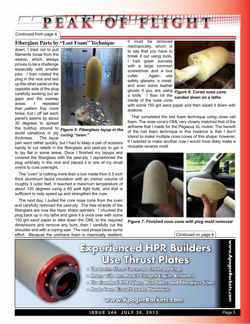
down, I tried not to pull filaments loose from the weave, which always proves to be a challenge especially with smaller jobs. I then rotated the plug in the vice and laid up the other panel on the opposite side of the plug carefully working out air gaps and the overlap areas. I repeated that pattern five more times, but I off set each panel’s seams by about 30 degrees to spread the buildup around to avoid variations in ply thickness. The layup part went rather quickly, but I had to keep a pair of scissors handy to cut reliefs in the fiberglass and peel-ply to get it to lay flat in some areas. Once I finished my layups and covered the fiberglass with the peel-ply, I repositioned the plug vertically in the vice and placed it in one of my small ovens to cure overnight.
The “oven” is nothing more than a box made from 0.5 inch thick aluminum faced insulation with an interior volume of roughly 3 cubic feet. It reached a maximum temperature of about 120 degrees using a 60 watt light bulb, and that is sufficient to help speed up and strengthen the cure.
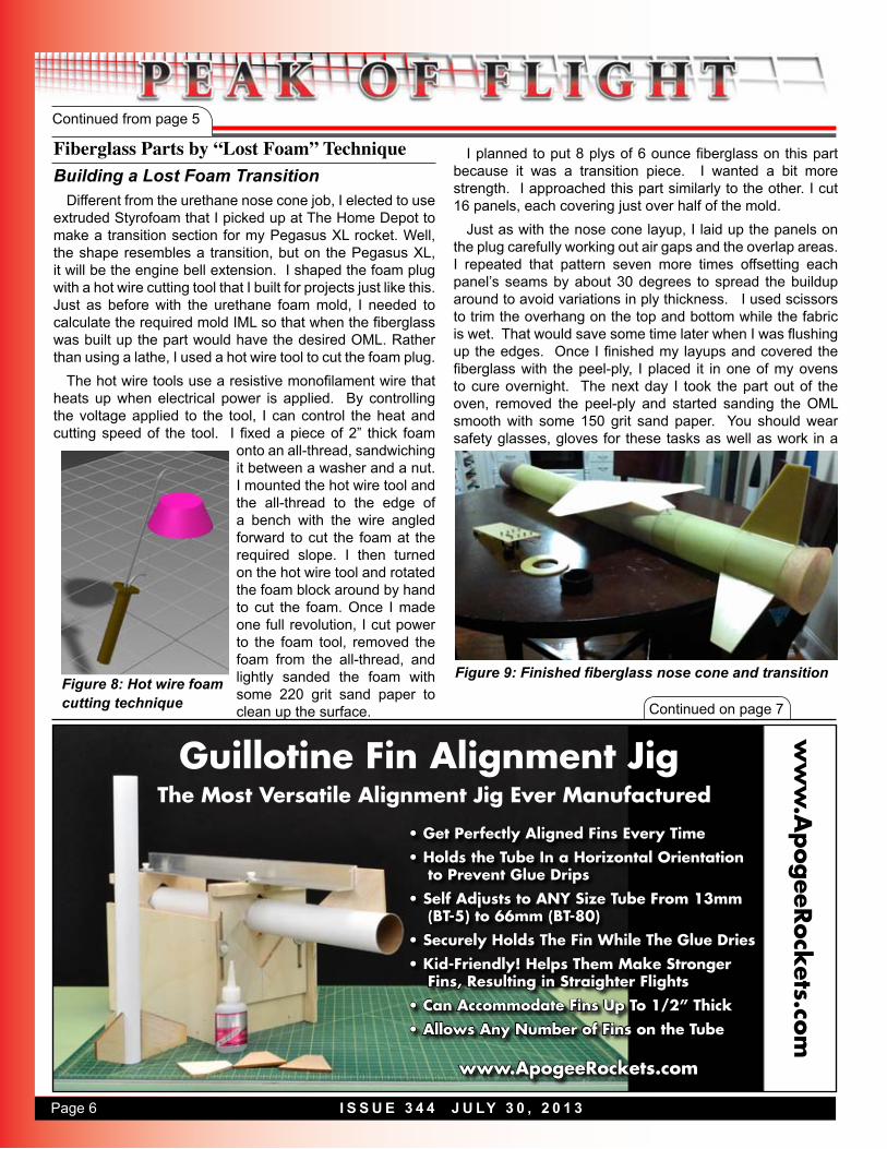
The next day, I pulled the cure nose cone from the oven and carefully removed the peel-ply. The free strands of the fiberglass are now like razor sharp splinters. I chucked the plug back up in my lathe and gave it a once over with some 150 grit sand paper to take down the OML to the required dimensions and remove any burs, then I carefully cut the shoulder end with a coping saw. The next phase takes some effort. Because the urethane foam is chemically resilient,
it must be removed mechanically, which is to say that you have to break it out using tools. I had great success with a large common screwdriver and a box cutter. Again, use safety glasses, a mask, and even some leather gloves if you are using a knife. I then hit the inside of the nose cone with some 150 grit sand paper and then wiped it down with acetone.
That completed the lost foam technique using close cell foam. The nose cone’s OML very closely matched that of the airframe that I made for the Pegasus XL rocket. The benefit of the lost foam technique in this instance is that I don’t intend to make multiple nose cones of this shape; however, if I wanted to make another now I would most likely make a reusable reverse mold.
Fiberglass Parts by “Lost Foam” Technique
Figure 5: Fiberglass layup in the curing “oven.”
Figure 6: Cured nose cone sanded down on a lathe
Figure 7: Finished nose cone with plug mold removed
Page 6 I S S U E 3 4 4 J U LY 3 0 , 2 0 1 3
Continued from page 5
ww
w.A
pog
eeRock
ets.com
Guillotine Fin Alignment Jig
• Get Perfectly Aligned Fins Every Time• Holds the Tube In a Horizontal Orientation
to Prevent Glue Drips• Self Adjusts to ANY Size Tube From 13mm
(BT-5) to 66mm (BT-80) • Securely Holds The Fin While The Glue Dries• Kid-Friendly! Helps Them Make Stronger
Fins, Resulting in Straighter Flights • Can Accommodate Fins Up To 1/2” Thick • Allows Any Number of Fins on the Tube
www.ApogeeRockets.com
The Most Versatile Alignment Jig Ever Manufactured
Building a Lost Foam TransitionDifferent from the urethane nose cone job, I elected to use
extruded Styrofoam that I picked up at The Home Depot to make a transition section for my Pegasus XL rocket. Well, the shape resembles a transition, but on the Pegasus XL, it will be the engine bell extension. I shaped the foam plug with a hot wire cutting tool that I built for projects just like this. Just as before with the urethane foam mold, I needed to calculate the required mold IML so that when the fiberglass was built up the part would have the desired OML. Rather than using a lathe, I used a hot wire tool to cut the foam plug.
The hot wire tools use a resistive monofilament wire that heats up when electrical power is applied. By controlling the voltage applied to the tool, I can control the heat and cutting speed of the tool. I fixed a piece of 2” thick foam
onto an all-thread, sandwiching it between a washer and a nut. I mounted the hot wire tool and the all-thread to the edge of a bench with the wire angled forward to cut the foam at the required slope. I then turned on the hot wire tool and rotated the foam block around by hand to cut the foam. Once I made one full revolution, I cut power to the foam tool, removed the foam from the all-thread, and lightly sanded the foam with some 220 grit sand paper to clean up the surface.
I planned to put 8 plys of 6 ounce fiberglass on this part because it was a transition piece. I wanted a bit more strength. I approached this part similarly to the other. I cut 16 panels, each covering just over half of the mold.
Just as with the nose cone layup, I laid up the panels on the plug carefully working out air gaps and the overlap areas. I repeated that pattern seven more times offsetting each panel’s seams by about 30 degrees to spread the buildup around to avoid variations in ply thickness. I used scissors to trim the overhang on the top and bottom while the fabric is wet. That would save some time later when I was flushing up the edges. Once I finished my layups and covered the fiberglass with the peel-ply, I placed it in one of my ovens to cure overnight. The next day I took the part out of the oven, removed the peel-ply and started sanding the OML smooth with some 150 grit sand paper. You should wear safety glasses, gloves for these tasks as well as work in a
Fiberglass Parts by “Lost Foam” Technique
Continued on page 7
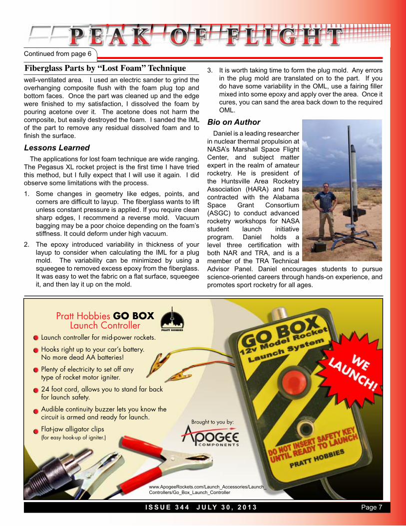
Figure 8: Hot wire foam cutting technique
Figure 9: Finished fiberglass nose cone and transition
Page 7I S S U E 3 4 4 J U LY 3 0 , 2 0 1 3
Continued from page 6
Launch controller for mid-power rockets.
Hooks right up to your car’s battery.No more dead AA batteries!
Plenty of electricity to set off any type of rocket motor igniter.
24 foot cord, allows you to stand far backfor launch safety.
Audible continuity buzzer lets you know the circuit is armed and ready for launch.
Flat-jaw alligator clips(for easy hook-up of igniter.)
Pratt Hobbies GO BOX Launch Controller
Brought to you by:
www.ApogeeRockets.com/Launch_Accessories/Launch_Controllers/Go_Box_Launch_Controller
well-ventilated area. I used an electric sander to grind the overhanging composite flush with the foam plug top and bottom faces. Once the part was cleaned up and the edge were finished to my satisfaction, I dissolved the foam by pouring acetone over it. The acetone does not harm the composite, but easily destroyed the foam. I sanded the IML of the part to remove any residual dissolved foam and to finish the surface.
Lessons LearnedThe applications for lost foam technique are wide ranging.
The Pegasus XL rocket project is the first time I have tried this method, but I fully expect that I will use it again. I did observe some limitations with the process. 1. Some changes in geometry like edges, points, and
corners are difficult to layup. The fiberglass wants to lift unless constant pressure is applied. If you require clean sharp edges, I recommend a reverse mold. Vacuum bagging may be a poor choice depending on the foam’s stiffness. It could deform under high vacuum.
2. The epoxy introduced variability in thickness of your layup to consider when calculating the IML for a plug mold. The variability can be minimized by using a squeegee to removed excess epoxy from the fiberglass. It was easy to wet the fabric on a flat surface, squeegee it, and then lay it up on the mold.
3. It is worth taking time to form the plug mold. Any errors in the plug mold are translated on to the part. If you do have some variability in the OML, use a fairing filler mixed into some epoxy and apply over the area. Once it cures, you can sand the area back down to the required OML.
Bio on AuthorDaniel is a leading researcher
in nuclear thermal propulsion at NASA’s Marshall Space Flight Center, and subject matter expert in the realm of amateur rocketry. He is president of the Huntsville Area Rocketry Association (HARA) and has contracted with the Alabama Space Grant Consortium (ASGC) to conduct advanced rocketry workshops for NASA student launch initiative program. Daniel holds a level three certification with both NAR and TRA, and is a member of the TRA Technical Advisor Panel. Daniel encourages students to pursue science-oriented careers through hands-on experience, and promotes sport rocketry for all ages.
Fiberglass Parts by “Lost Foam” Technique