Embed Size (px)
DESCRIPTION
fiber home user guide
Citation preview
AN5506-04
GPON Optical Network Unit
User Manual
FiberHome Telecommunication Technologies Co., Ltd.
October 2009


Thank you for choosing our products!
We appreciate your business. Your satisfaction is our
goal. We will provide you with comprehensive technical
support and after-sales service. Please contact your
local sales representative, service representative or
distributor for any help needed by one of the following
methods.
Fiberhome Telecommunication Technologies Co., Ltd.
Address: No. 5 Dongxin Rd., Hongshan Dist., Wuhan, China
Zip code: 430073
Tel: +86-27-87691549
Fax: +86-27-87691755
Website: http: //www.fiberhomegroup.com

All Rights Reserved
No part of this document (including the electronic version)
may be reproduced or disseminated in any form or by any
means without prior written permission of FiberHome
Telecommunication Technologies Co., Ltd. (Hereinafter
referred to as FiberHome)
Information in this document is subject to change without
notice.


Trademarks
are trademarks of FiberHome Telecommunication Technologies Co., Ltd.
All other trademarks mentioned in this document are the property of their respective owners.
TM
TM TM


I
Operation Safety Rules
~ High optical power is harmful to human body, especially to
eyes. Never look directly into the end face of pigtail fiber of
optical transmitter or the end face of its active connector.
Α Exercise care if you must bend fibers. If necessary, the fiber
bending radius should not be less than 38 mm.
Α Power supply sockets with too heavy load or broken cables
and plugs may cause electric shock or fire. Users should
check the power supply wires and cables regularly. If there is
any breakage, please replace the cable at once.
Α Please adopt the power supply adapter provided for this
equipment. Otherwise the equipment may be damaged or not
able to run normally.
Α The equipment should be installed at positions with good
ventilation conditions and without high temperature or direct
sunshine, so as to avoid faults of the equipment and its
corresponding components due to overheat.

II
Α For communication equipment, users should note to avoid
humidification, especially prevent water from entering the
equipment. Entering of water can cause abnormal running of
the equipment and even other dangers due to short circuit.
Α Do not lay this equipment on unsteady base.

III
Packing List
After opening the packing case of AN5506-04, please check whether the
corresponding articles are in the packing case according to Packing List
as below:
Name Quantity Remark
AN5506-04 equipment 1 —
Certificate of conformity 1 —
Bag for document 1 There is an AN5506-04 GPON User
Manual.
USB storage battery power
adapter 1 Optional.
Wall-hung screws 2 For wall-hung fixation.

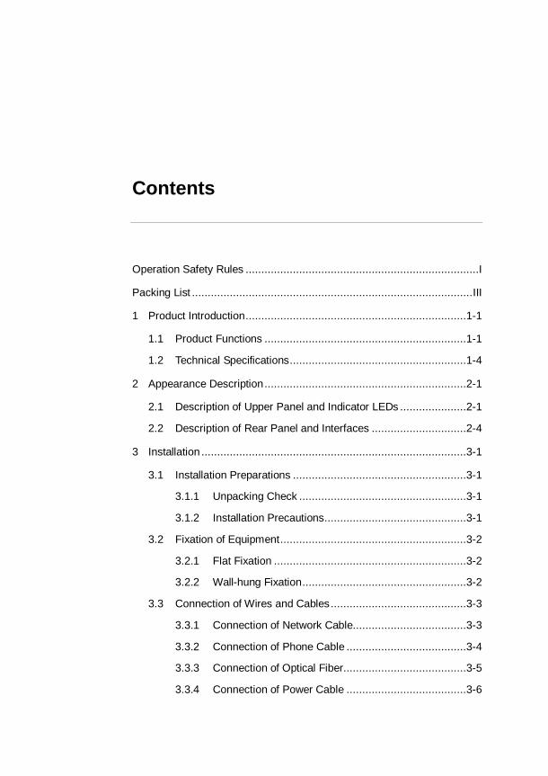
Contents
Operation Safety Rules ..........................................................................I
Packing List ......................................................................................... III
1 Product Introduction ......................................................................1-1
1.1 Product Functions ................................................................1-1
1.2 Technical Specifications ........................................................1-4
2 Appearance Description ................................................................2-1
2.1 Description of Upper Panel and Indicator LEDs .....................2-1
2.2 Description of Rear Panel and Interfaces ..............................2-4
3 Installation ....................................................................................3-1
3.1 Installation Preparations .......................................................3-1
3.1.1 Unpacking Check .....................................................3-1
3.1.2 Installation Precautions .............................................3-1
3.2 Fixation of Equipment ...........................................................3-2
3.2.1 Flat Fixation .............................................................3-2
3.2.2 Wall-hung Fixation ....................................................3-2
3.3 Connection of Wires and Cables ...........................................3-3
3.3.1 Connection of Network Cable....................................3-3
3.3.2 Connection of Phone Cable ......................................3-4
3.3.3 Connection of Optical Fiber .......................................3-5
3.3.4 Connection of Power Cable ......................................3-6

AN5506-04 GPON Optical Network Unit User Manual
3.4 Examination after Installation ................................................3-8
4 Frequently Asked Questions and Answers .....................................4-1
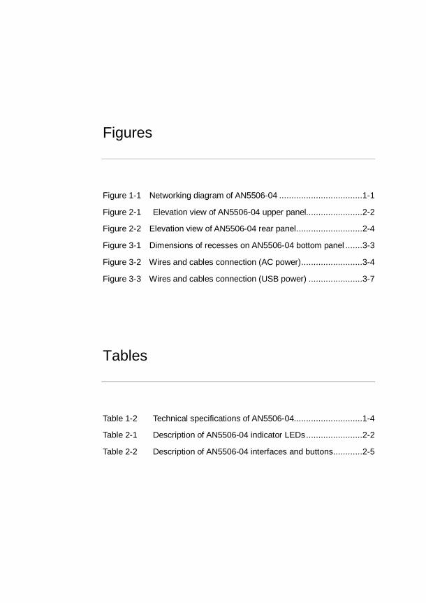
Figures
Figure 1-1 Networking diagram of AN5506-04 ..................................1-1
Figure 2-1 Elevation view of AN5506-04 upper panel.......................2-2
Figure 2-2 Elevation view of AN5506-04 rear panel ...........................2-4
Figure 3-1 Dimensions of recesses on AN5506-04 bottom panel .......3-3
Figure 3-2 Wires and cables connection (AC power) .........................3-4
Figure 3-3 Wires and cables connection (USB power) ......................3-7
Tables
Table 1-2 Technical specifications of AN5506-04............................1-4
Table 2-1 Description of AN5506-04 indicator LEDs .......................2-2
Table 2-2 Description of AN5506-04 interfaces and buttons ............2-5

1-1
1 Product Introduction
1.1 Product Functions
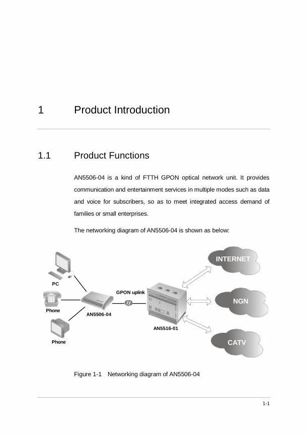
AN5506-04 is a kind of FTTH GPON optical network unit. It provides
communication and entertainment services in multiple modes such as data
and voice for subscribers, so as to meet integrated access demand of
families or small enterprises.
The networking diagram of AN5506-04 is shown as below:
NGN
INTERNET
CATV
GPON uplink
AN5506-04
Phone
Phone
PC
AN5516-01
Figure 1-1 Networking diagram of AN5506-04
AN5506-04 GPON Optical Network Unit User Manual
1-2
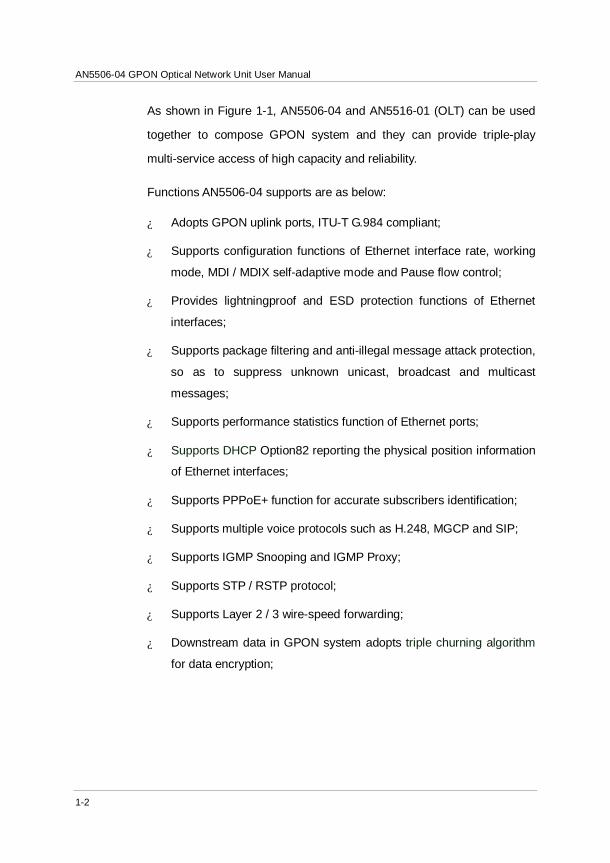
As shown in Figure 1-1, AN5506-04 and AN5516-01 (OLT) can be used
together to compose GPON system and they can provide triple-play
multi-service access of high capacity and reliability.
Functions AN5506-04 supports are as below:
¿ Adopts GPON uplink ports, ITU-T G.984 compliant;
¿ Supports configuration functions of Ethernet interface rate, working
mode, MDI / MDIX self-adaptive mode and Pause flow control;
¿ Provides lightningproof and ESD protection functions of Ethernet
interfaces;
¿ Supports package filtering and anti-illegal message attack protection,
so as to suppress unknown unicast, broadcast and multicast
messages;
¿ Supports performance statistics function of Ethernet ports;
¿ Supports DHCP Option82 reporting the physical position information
of Ethernet interfaces;
¿ Supports PPPoE+ function for accurate subscribers identification;
¿ Supports multiple voice protocols such as H.248, MGCP and SIP;
¿ Supports IGMP Snooping and IGMP Proxy;
¿ Supports STP / RSTP protocol;
¿ Supports Layer 2 / 3 wire-speed forwarding;
¿ Downstream data in GPON system adopts triple churning algorithm
for data encryption;

1 Product Introduction
1-3
¿ Supports powerful QoS function; supports global configuration of
queue priority and flexible mapping of 802.1p value of messages;
supports three scheduling modes: PQ, WRR or PQ+WRR; can
configure the weight of scheduling queue to ensure QoS of key
services such as VoIP and IPTV under multiple service conditions.
AN5506-04 GPON Optical Network Unit User Manual
1-4
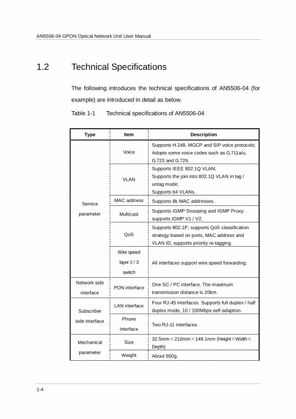
1.2 Technical Specifications
The following introduces the technical specifications of AN5506-04 (for
example) are introduced in detail as below.
Table 1-1 Technical specifications of AN5506-04
Type Item Description
Service
parameter
Voice Supports H.248, MGCP and SIP voice protocols; Adopts some voice codes such as G.711a/u, G.723 and G.729.
VLAN
Supports IEEE 802.1Q VLAN; Supports the join into 802.1Q VLAN in tag / untag mode; Supports 64 VLANs.
MAC address Supports 8k MAC addresses.
Multicast Supports IGMP Snooping and IGMP Proxy; supports IGMP V1 / V2.
QoS Supports 802.1P; supports QoS classification strategy based on ports, MAC address and VLAN ID, supports priority re-tagging.
Wire speed
layer 2 / 3
switch
All interfaces support wire speed forwarding.
Network side
interface PON interface One SC / PC interface. The maximum
transmission distance is 20km.
Subscriber
side interface
LAN interface Four RJ-45 interfaces. Supports full duplex / half duplex mode, 10 / 100Mbps self-adaption.
Phone
interface Two RJ-11 interfaces.
Mechanical
parameter
Size 32.5mm×210mm×149.1mm (Height×Width×Depth)
Weight About 650g.
1 Product Introduction
1-5
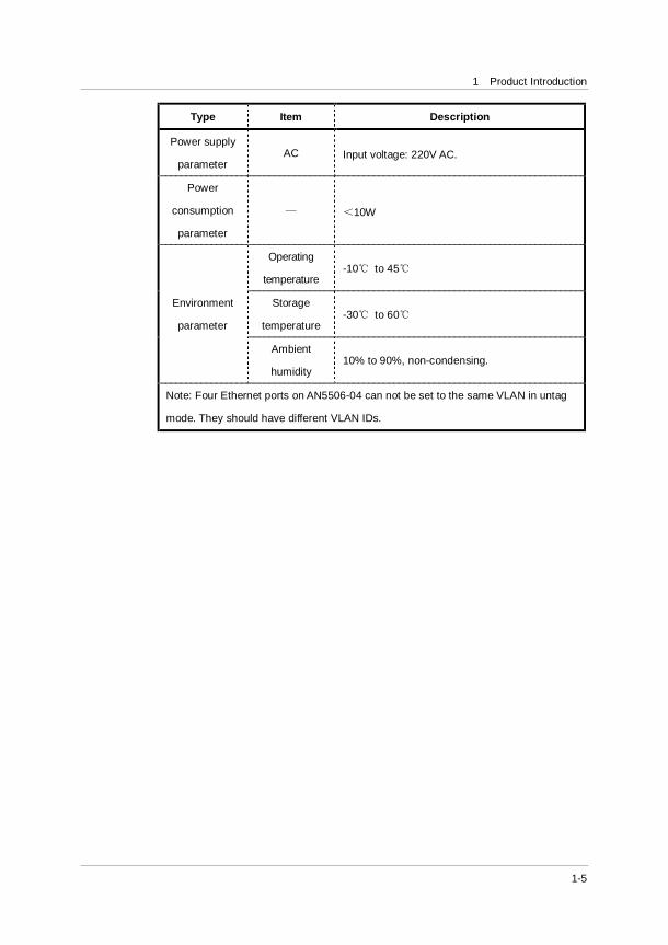
Type Item Description
Power supply
parameter AC Input voltage: 220V AC.
Power
consumption
parameter
— <10W
Environment
parameter
Operating
temperature -10℃ to 45℃
Storage
temperature -30℃ to 60℃
Ambient
humidity 10% to 90%, non-condensing.
Note: Four Ethernet ports on AN5506-04 can not be set to the same VLAN in untag
mode. They should have different VLAN IDs.


2-1
2 Appearance Description
2.1 Description of Upper Panel and Indicator LEDs
This chapter describes AN5506-04’s appearance in detail.
The equipment body of AN5506-04 adopts hollow-carved streamline
design with novel and fashionable appearance. There are some indicator
LEDs on the upper panel indicating the running state of equipment, so
that subscribers can understand the equipment state directly.
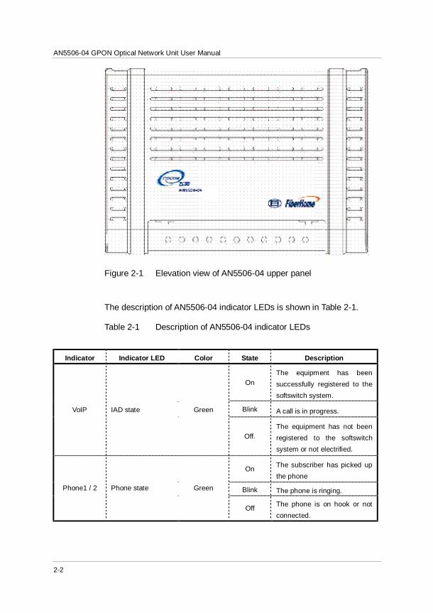
The upper panel of AN5506-04 is shown in Figure 2-1 and the indicator
LEDs are shown in Table 2-1.
AN5506-04 GPON Optical Network Unit User Manual
2-2
Figure 2-1 Elevation view of AN5506-04 upper panel
The description of AN5506-04 indicator LEDs is shown in Table 2-1.
Table 2-1 Description of AN5506-04 indicator LEDs
Indicator Indicator LED Color State Description
VoIP IAD state Green
On The equipment has been successfully registered to the softswitch system.
Blink A call is in progress.
Off. The equipment has not been registered to the softswitch system or not electrified.
Phone1 / 2 Phone state Green
On The subscriber has picked up the phone
Blink The phone is ringing.
Off The phone is on hook or not connected.
2 Appearance Description
2-3
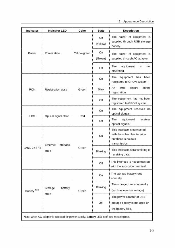
Indicator Indicator LED Color State Description
Power Power state Yellow-green
On
(Yellow)
The power of equipment is supplied through USB storage battery.
On
(Green) The power of equipment is supplied through AC adapter.
Off The equipment is not electrified.
PON Registration state Green
On The equipment has been registered to GPON system.
Blink An error occurs during registration.
Off The equipment has not been registered to GPON system.
LOS Optical signal state Red
On The equipment receives no optical signals.
Off The equipment receives optical signals.
LAN1/ 2 / 3 / 4 Ethernet interface
state Green
On
This interface is connected with the subscriber terminal but there is no data transmission.
Blinking This interface is transmitting or receiving data.
Off This interface is not connected with the subscriber terminal.
Battery Note Storage battery
state Green
On The storage battery runs normally.
Blinking The storage runs abnormally
(such as overlow voltage)
Off.
The power adapter of USB
storage battery is not used or
the battery fails.
Note: when AC adapter is adopted for power supply, Battery LED is off and meaningless.
AN5506-04 GPON Optical Network Unit User Manual
2-4
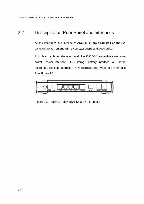
2.2 Description of Rear Panel and Interfaces
All the interfaces and buttons of AN5506-04 are distributed on the rear
panel of the equipment, with a compact shape and good utility.
From left to right, on the rear panel of AN5506-04 respectively are power
switch, power interface, USB storage battery interface, 4 Ethernet
interfaces, Console interface, PON interface and two phone interfaces.
See Figure 2-2.
Figure 2-2 Elevation view of AN5506-04 rear panel
2 Appearance Description
2-5
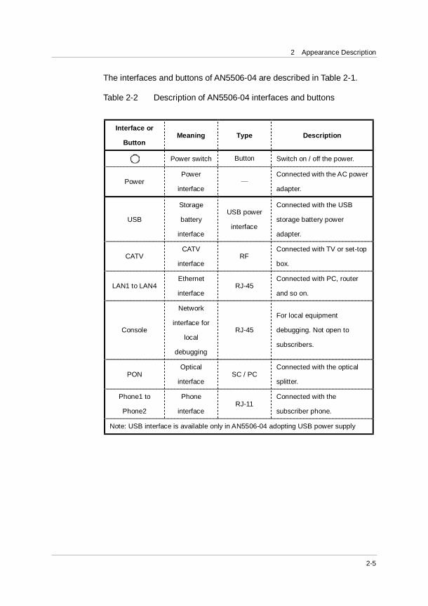
The interfaces and buttons of AN5506-04 are described in Table 2-1.
Table 2-2 Description of AN5506-04 interfaces and buttons
Interface or
Button Meaning Type Description
Power switch Button Switch on / off the power.
Power Power
interface —
Connected with the AC power
adapter.
USB
Storage
battery
interface
USB power
interface
Connected with the USB
storage battery power
adapter.
CATV CATV
interface RF
Connected with TV or set-top
box.
LAN1 to LAN4 Ethernet
interface RJ-45
Connected with PC, router
and so on.
Console
Network
interface for
local
debugging
RJ-45
For local equipment
debugging. Not open to
subscribers.
PON Optical
interface SC / PC
Connected with the optical
splitter.
Phone1 to
Phone2
Phone
interface RJ-11
Connected with the
subscriber phone.
Note: USB interface is available only in AN5506-04 adopting USB power supply

3-1
3 Installation
3.1 Installation Preparations
3.1.1 Unpacking Check
After opening the packing case of AN5506-04, please check articles in the
packing case according to Packing List. If it is found that articles in the
packing case do not comply with the list, please contact the local office of
FiberHome directly.
3.1.2 Installation Precautions
Before installing AN556-04 please ensure that the following requirements
are met:
¿ There are waterproof, moistureproof and lightningproof conditions at
the installation position.
¿ The installation position can provide conditions for AN5506-04 to
connect with the exterior. For example, there should be suitable
outlet space for power supply cable and network cable.
¿ The installation position should be able to ensure enough air flow,
convenient for cooling of the equipment.

AN5506-04 GPON Optical Network Unit User Manual
3-2
3.2 Fixation of Equipment
AN5506-04 can be laid on a stable plane (such as a desk), or be hung on
the wall. Subscribers can select suitable installation mode on their
demand. The fixation methods of the two modes are as follows.
3.2.1 Flat Fixation
1) Take out AN5506-04 equipment from the packing case. Before
delivery, four rubber pads are pasted to four corners on the bottom of
the equipment;
2) Lay AN5506-04 on a steady desk slightly and ensure the ventilation
on both right and left sides.
3.2.2 Wall-hung Fixation
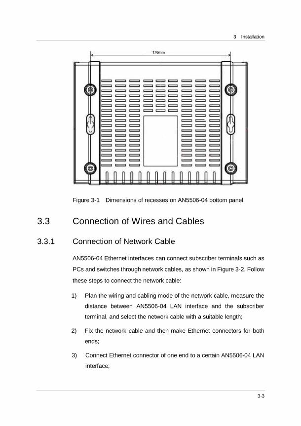
1) According to the recesses distance (170mm) marked in Figure 3-1,
fix two wall-hung screws attached to AN5506-04 into the wall.
2) Align the recesses on AN5506-04 bottom panel with the screws and
fix up slightly.
3) Let go slowly. AN5506-04 is hung on the wall with the support of
screws.
3 Installation
3-3
Figure 3-1 Dimensions of recesses on AN5506-04 bottom panel
3.3 Connection of Wires and Cables
3.3.1 Connection of Network Cable
AN5506-04 Ethernet interfaces can connect subscriber terminals such as
PCs and switches through network cables, as shown in Figure 3-2. Follow
these steps to connect the network cable:
1) Plan the wiring and cabling mode of the network cable, measure the
distance between AN5506-04 LAN interface and the subscriber
terminal, and select the network cable with a suitable length;
2) Fix the network cable and then make Ethernet connectors for both
ends;
3) Connect Ethernet connector of one end to a certain AN5506-04 LAN
interface;
AN5506-04 GPON Optical Network Unit User Manual
3-4
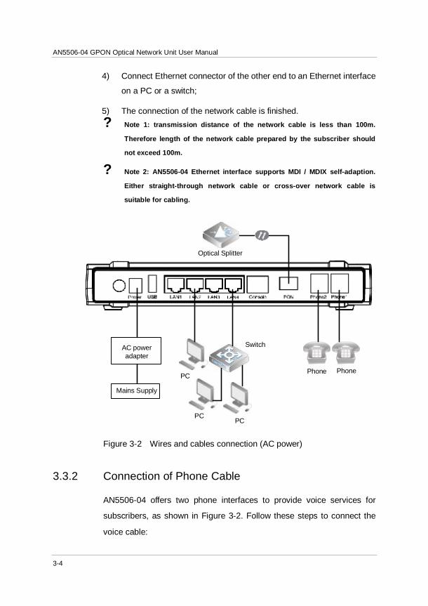
4) Connect Ethernet connector of the other end to an Ethernet interface
on a PC or a switch;
5) The connection of the network cable is finished. ? Note 1: transmission distance of the network cable is less than 100m.
Therefore length of the network cable prepared by the subscriber should
not exceed 100m.
? Note 2: AN5506-04 Ethernet interface supports MDI / MDIX self-adaption.
Either straight-through network cable or cross-over network cable is
suitable for cabling.
AC power adapter
Mains Supply
PC
PCPC
Optical Splitter
Phone Phone
Switch
Figure 3-2 Wires and cables connection (AC power)
3.3.2 Connection of Phone Cable
AN5506-04 offers two phone interfaces to provide voice services for
subscribers, as shown in Figure 3-2. Follow these steps to connect the
voice cable:
3 Installation
3-5
1) Plan the wiring and cabling mode of the phone cable, measure the
distance between AN5506-04 Phone interface and the subscriber
phone, and select the phone cable with a suitable length;
2) Fix the phone cable and then make RJ-11 connectors for both ends;
3) Connect one end of the phone cable to a certain AN5506-04 Phone
interface;
4) Connect the other end to a subscriber phone;
5) The connection of the phone cable is finished.
3.3.3 Connection of Optical Fiber
AN5506-04 adopts wavelength division multiplexing (WDM) mode and
provides “triple-play” integrated access, as shown in Figure 3-2. The
connection steps of optical fibers are as below:
1) Plan the wires and cables layout mode of the optical fiber; measure
the distance between AN5506-04 PON interface and upstream
optical splitter; select the optical jumper with suitable length;
2) Fix the optical fiber; remove the protection covers of the optical
jumper and AN5506-04 optical interface;
3) Insert one end of the optical jumper into AN5506-04 PON interface
slightly;
4) Connect the other end of the optical jumper with the optical splitter;
5) The connection of optical fibers is finished.
Α Caution 1: if the optical fiber jumpers are not used, make sure
optical fiber jumpers and AN5506-04 optical interfaces are
covered to avoid dust contamination and water penetration,
which lead to the uselessness of optical fiber jumpers and
AN5506-04 optical interfaces.
AN5506-04 GPON Optical Network Unit User Manual
3-6
Α Caution 2: connect optical fibers at last if possible. Lay
optical fibers at the position without extrusion.
3.3.4 Connection of Power Cable
AN5506-04 allows two modes of power supply: AC power and USB
storage battery. Their connections are introduced below respectively.
AC Power Connection
1) Take out the provided AC power adapter;
2) Connect one end of the adapter to Power interface of AN5506-04;
3) Connect the other end to mains supply socket, as shown in Figure
3-2;
4) The connection of power cable is finished. ? Note: This power adapter can convert 220V AC into 12V DC input for
AN5506-04 so as to supply power to the equipment.
USB Storage Battery Power Connection
USB storage battery power adapter integrates a DC storage battery which
serves as a standby power supply and enables the equipment to keep
running for 6 to 7 hours in the case of power failure. It lifts operational
reliability of the equipment. Follow these steps to connect the power
cable.
1) Take out the provided USB storage battery power adapter;
2) Connect one end of the adapter to USB power interface on
AN5506-04;
3) Connect the other end to mains supply socket, as shown in Figure
3-3;
4) The connection of power cable is finished.
3 Installation
3-7
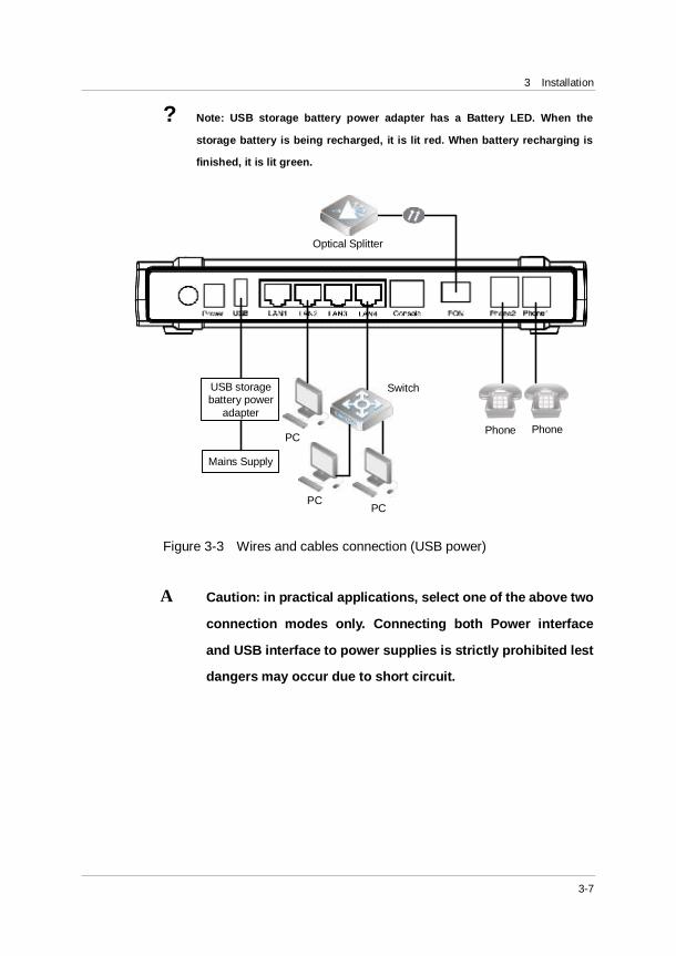
? Note: USB storage battery power adapter has a Battery LED. When the
storage battery is being recharged, it is lit red. When battery recharging is
finished, it is lit green.
USB storage battery power
adapter
Mains Supply
PC
PCPC
Optical Splitter
Phone Phone
Switch
Figure 3-3 Wires and cables connection (USB power)
Α Caution: in practical applications, select one of the above two
connection modes only. Connecting both Power interface
and USB interface to power supplies is strictly prohibited lest
dangers may occur due to short circuit.
AN5506-04 GPON Optical Network Unit User Manual
3-8
3.4 Examination after Installation
After the connection of wires and cables is finished and relevant services
are started up by the operator, it needs to power on and examine
AN5506-04 as below:
1) Switch on the power.
2) Observe the status of Power indicator LED. If Power indicator LED
is ON, it means the power-on of equipment is normal; otherwise,
please check whether the connection of power cable is correct.
3) If USB storage battery is adopted for power supply, subscribers
should observe the status of Battery indicator LED. If Battery
indictor LED is ON, it means the power cable of USB storage battery
is connected normally; otherwise, check whether the connection of
USB storage battery power cable is correct.
4) Observe the status of LOS indicator LED. If LOS indicator LED is
OFF, it means the optical fiber connection is normal; otherwise,
please check whether the connection of optical fibers is correct.
5) Observe the status of LAN indicator LED. If LAN indicator LED is
ON or blinks, it means the network cable is connected normally;
otherwise, please check whether the connection of network cable is
correct.
6) Observe the status of Phone indicator LED. If before and after the
phone is picked up, Phone indicator LED turns OFF to ON, it means
the phone cable is connected normally; otherwise, please check
whether the connection of phone cable is correct.
7) Ensure the ventilation around during equipment running to avoid
problems because of overheating. Check the running status of the
fan at any moment. For abnormity, contact the local office of
FiberHome for replacement, so as not to affect equipment running.
4-1
4 Frequently Asked Questions and Answers
Q: All indicator LEDs are OFF after power-on.
A: 1) Check whether the power connection cable is connected well;
2) Check whether the power switch on the equipment front panel is ON.
Q: The equipment fails to work after a period of normal running.
A: 1) If the equipment works abnormally, check whether the power is connected normally or the voltage is over high or over low;
2) The equipment has over-heat fault. Check whether the ventilation is normal and check whether there is direct sunshine or heat source around.
Q: LOS indicator LED is ON.
A: 1) The optical fiber is faulty. Check whether the optical fiber is connected normally and whether it is connected to correct interface;
2) The upstream equipment is faulty;
3) The optical power is out of the normal range (such as overload).
Q: Battery indicator LED blinks or turns OFF.
A: 1) If Battery indicator LED blinks, it means that the battery works abnormally or the voltage is over low. Recharge it in time;
AN5506-04 GPON Optical Network Unit User Manual
4-2
2) If Battery indicator LED turns OFF, check whether USB power cable is connected normally;
3)If Battery indicator LED turns OFF, check whether the storage battery expires or has faults.
Q: LAN indicator LED is OFF.
A: 1) Check whether the network cable is damaged or its connection is loose;
2) Check whether the network cable is made correctly. If it is incorrect, replace it with a new network cable made according to the standard method (for making a CAT 5 twisted-pair cable);
3) Check whether the network cable length exceeds allowable range.

FFeeeeddbbaacckk FFoorrmm
Your feedback is an important way for us to receive questions, comments and suggestions...ultimately providing you with enhanced manuals and services by FiberHome.
1. Please give your opinions on the items listed below about this manual by the symbol “√”.
Items Excellent Good Normal Bad
Expression £ £ £ £
Integrity £ £ £ £
Exactitude £ £ £ £
Structure £ £ £ £
Illustration £ £ £ £
Getup £ £ £ £
General £ £ £ £
2. Please give your advices on the items listed below about this manual by the symbol “√”.
£ Adjust its structure £ Contents more detailed
£ Give more examples £ Expression more concise
£ Add more illustrations £ Operationality more ascensive
Please give more details of your advices on this manual:
3. Which part of this manual do you appreciate more?
4. Other advices for our manuals:
5. The personal information requested is used for no other purposes than to respond to your feedback
Name Job/Position Working Unit E-mail Correspondence Phone Num Correspondence Facsimile Correspondence Address Date


FiberHome Telecommunication Technologies Co., Ltd.
Address: No. 5 Dongxin Rd., Hongshan Dist., Wuhan, China
Zip code: 430073
Tel: +86-27-87691549
Fax: +86-27-87691755
Website: http://www.fiberhomegroup.com