Embed Size (px)
Citation preview

Field Challenges with DCV Systems
Dr. Andrey Livchak, Derek Schrock and Jimmy SanduskyHalton Group Americas
www.halton.com
Overview
• One of the key challenges of implementing DCV systems in the field is to ensure that the hoods are operating at capture and containment (C&C) airflows when the appliances are in a cooking mode. Data is presented on how different appliances can require additional detection methods to ensure that the hood is running at a proper airflow.
• Secondly, a case study is presented on the design challenge of how to incorporate a DCV system in a restaurant which has a combination of hoods with dedicated exhaust fans and hoods that share exhaust fans; and how to optimize the energy consumption of these systems.
DCV Testing with Appliances
• Testing conducted with a range of appliances installed under a hood with various simulated DCV control schemes:– Exhaust Temperature + Cooking Activity Sensor– Exhaust Temperature Only (Operating on a Curve)– Exhaust Temperature Only (Operating at a Fixed
Exhaust Set-Point)
DCV with cooking activity sensor
• Two types of cooking activity sensors are available on the market:– one uses infrared light beam across the hood to
detect visible smoke or stream associated with the beginning of cooking process
– another uses infrared temperature sensors to continuously monitor surface temperature of appliances under the hood
DCV Control Details
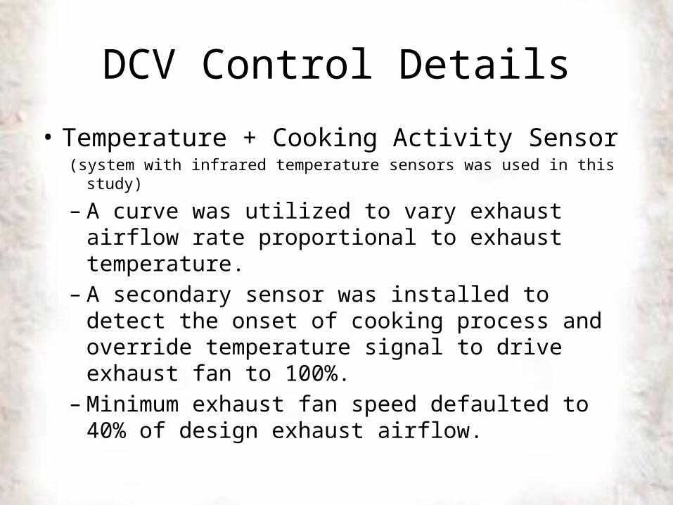
• Temperature + Cooking Activity Sensor(system with infrared temperature sensors was used in this study)
– A curve was utilized to vary exhaust airflow rate proportional to exhaust temperature.
– A secondary sensor was installed to detect the onset of cooking process and override temperature signal to drive exhaust fan to 100%.
– Minimum exhaust fan speed defaulted to 40% of design exhaust airflow.
DCV Control Details
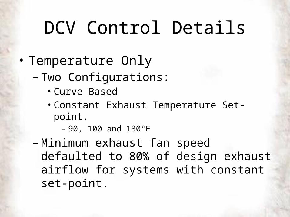
• Temperature Only– Two Configurations:• Curve Based• Constant Exhaust Temperature Set-point.
– 90, 100 and 130°F
– Minimum exhaust fan speed defaulted to 80% of design exhaust airflow for systems with constant set-point.
DCV Control Details
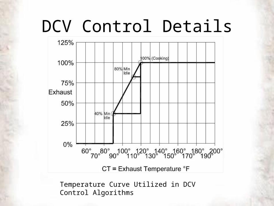
Temperature Curve Utilized in DCV Control Algorithms
DCV Testing Configuration
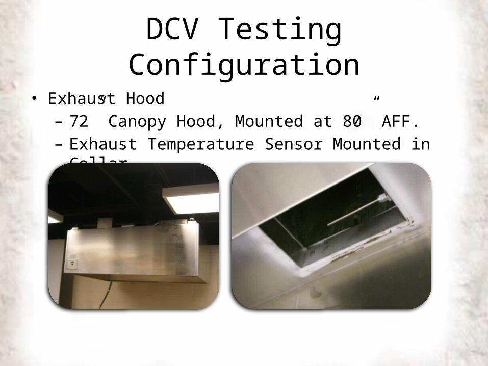
• Exhaust Hood– 72” Canopy Hood, Mounted at 80” AFF.– Exhaust Temperature Sensor Mounted in Collar
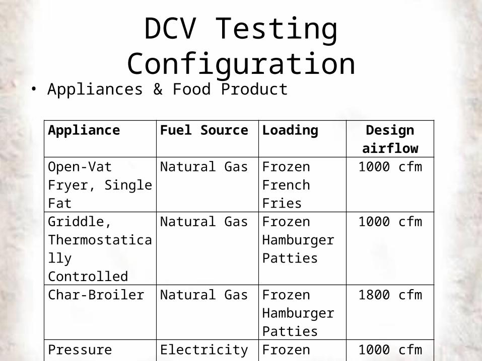
DCV Testing Configuration• Appliances & Food Product
Appliance Fuel Source Loading Design airflowOpen-Vat Fryer, Single Fat
Natural Gas Frozen French Fries
1000 cfm
Griddle, Thermostatically Controlled
Natural Gas Frozen Hamburger Patties
1000 cfm
Char-Broiler Natural Gas Frozen Hamburger Patties
1800 cfm
Pressure Fryer, Single Vat
Electricity Frozen Chicken Patties
1000 cfm
Re-Thermalizer, Dual Vat
Natural Gas Frozen Taco Meat
1000 cfm
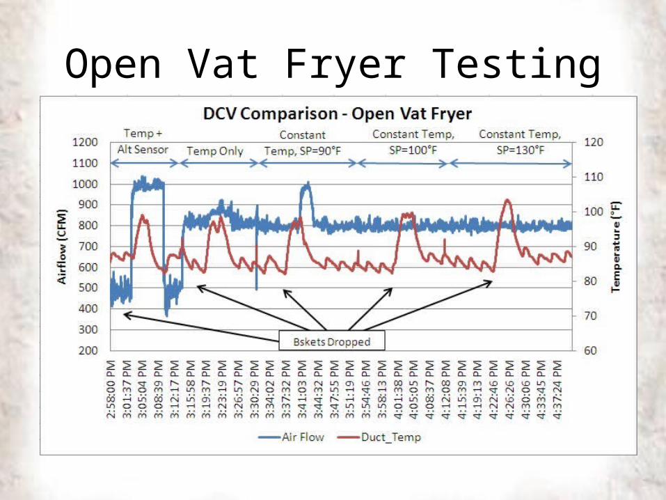
Open Vat Fryer Testing
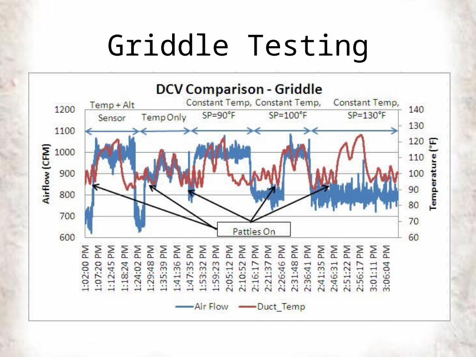
Griddle Testing
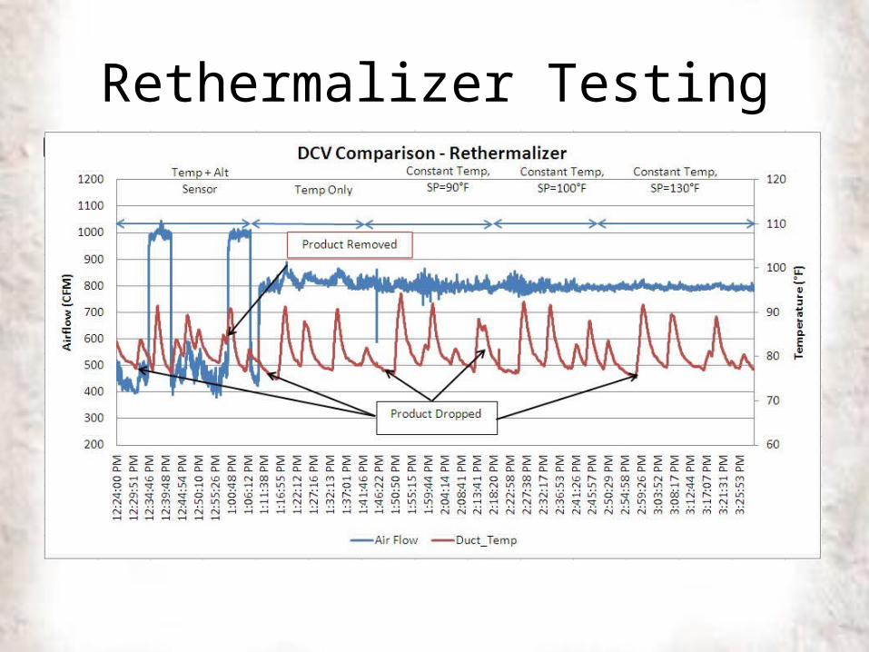
Rethermalizer Testing
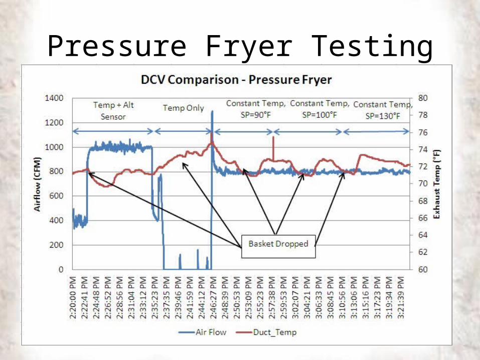
Pressure Fryer Testing
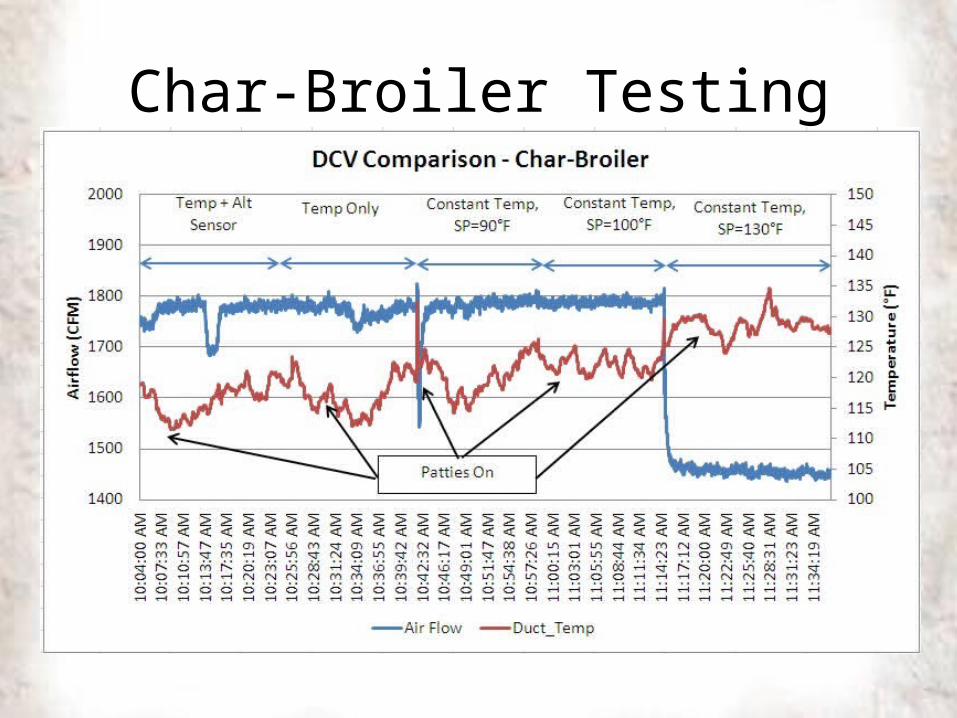
Char-Broiler Testing
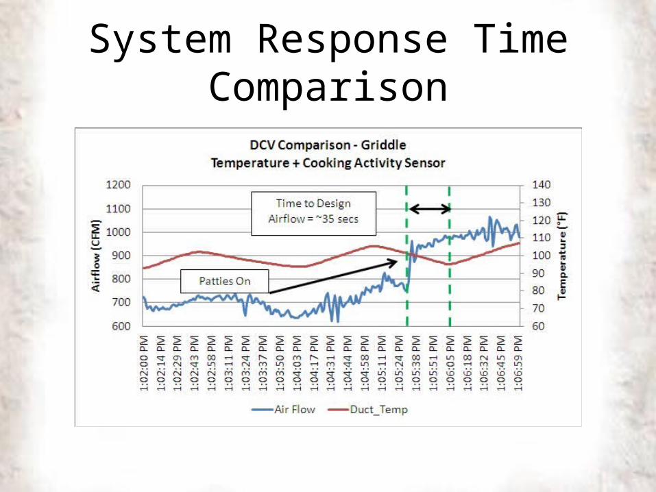
System Response Time Comparison
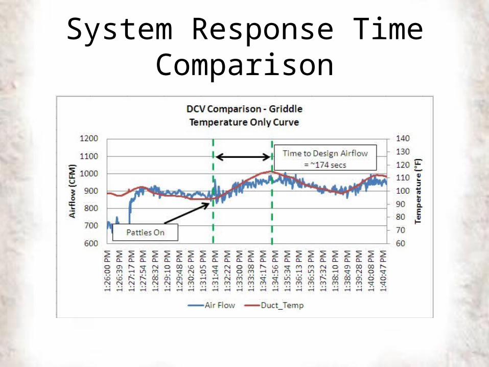
System Response Time Comparison
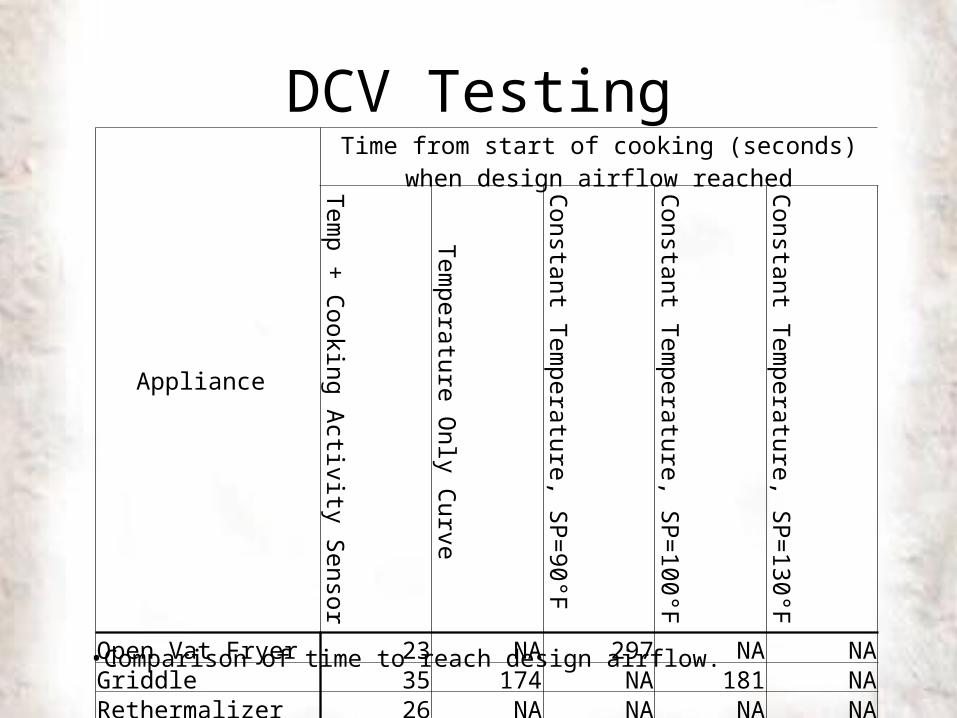
DCV Testing
•Comparison of time to reach design airflow.
Appliance
Time from start of cooking (seconds) when design airflow reached
Temp + Cooking Activity Sensor
Temperature Only Curve
Constant Temperatu
re, SP=90°F
Constant Temperatu
re, SP=100°F
Constant Temperatu
re, SP=130°F
Open Vat Fryer 23 NA 297 NA NAGriddle 35 174 NA 181 NARethermalizer 26 NA NA NA NAPressure fryer 28 NA NA NA NAChar-Broiler 23 NA NA NA NA
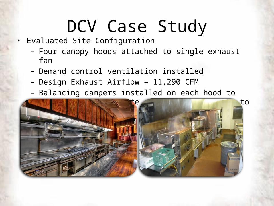
DCV Case Study• Evaluated Site Configuration
– Four canopy hoods attached to single exhaust fan – Demand control ventilation installed– Design Exhaust Airflow = 11,290 CFM– Balancing dampers installed on each hood to independently regulate
exhaust proportional to demand
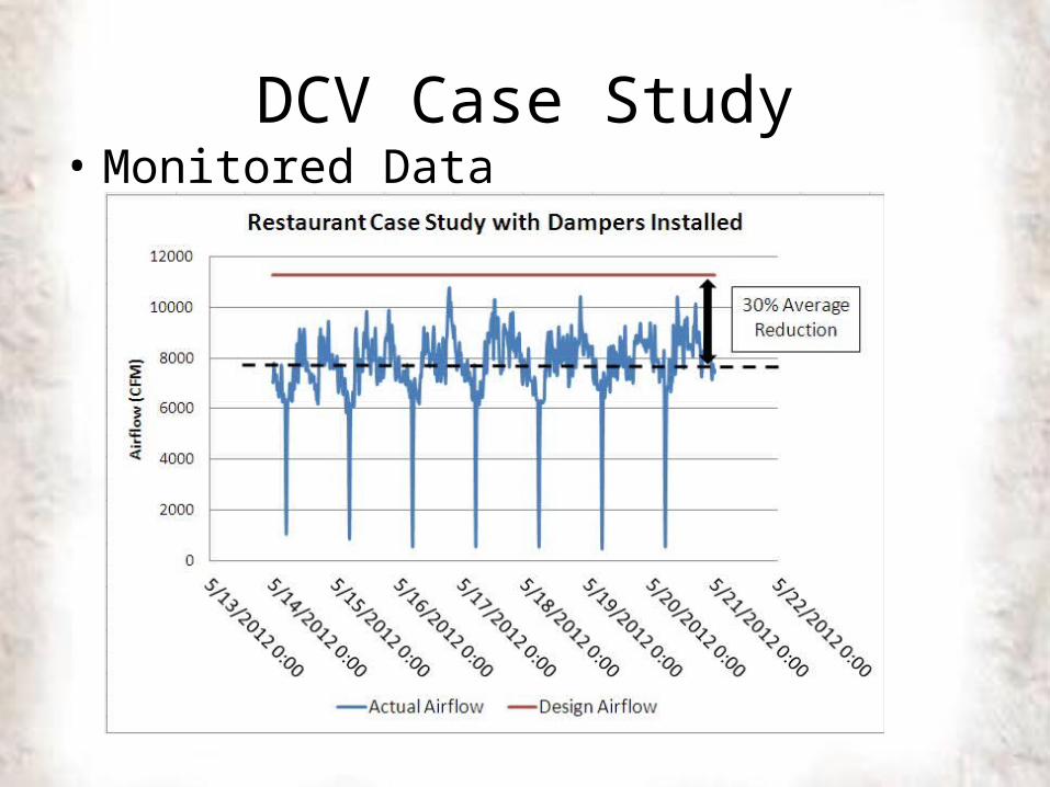
DCV Case Study• Monitored Data
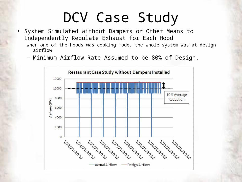
DCV Case Study• System Simulated without Dampers or Other Means to Independently
Regulate Exhaust for Each Hoodwhen one of the hoods was cooking mode, the whole system was at design airflow
– Minimum Airflow Rate Assumed to be 80% of Design.
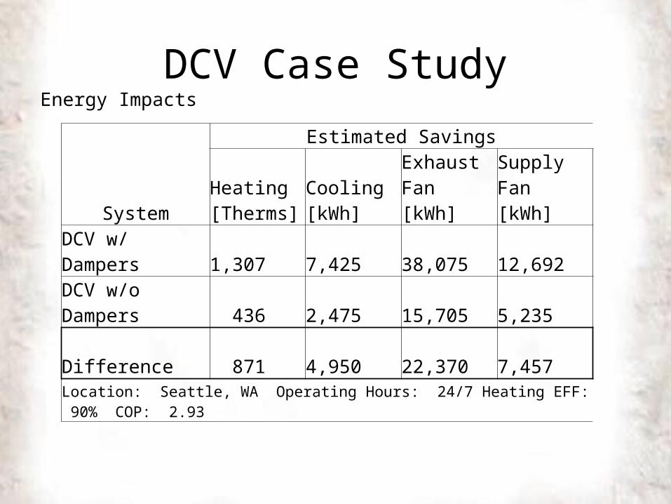
DCV Case StudyEnergy Impacts
System
Estimated Savings
Heating [Therms]
Cooling [kWh]
Exhaust Fan [kWh]
Supply Fan [kWh]
DCV w/ Dampers 1,307 7,425 38,075 12,692
DCV w/o Dampers 436 2,475 15,705 5,235
Difference 871 4,950 22,370 7,457
Location: Seattle, WA Operating Hours: 24/7 Heating EFF: 90% COP: 2.93
Conclusions1. Secondary cooking activity sensors are needed in addition to exhaust
temperature to minimize hood spillage Ideally DCV controller receives signal directly from cooking appliances’
controllers
2. Response time from exhaust temperature only systems is over 2 minutes for fryer and griddle resulting in hood spillage.
3. Set-points for temperature only systems need to be calibrated for a given application (appliance combination). They need to be reset for winter and summer to account for variation in kitchen space temperature unless space temperature sensor is used for automatic reset
4. Systems that couple multiple hoods to a single exhaust fan need a means of independently regulating exhaust airflow for each hood to maximize energy savings