Embed Size (px)
Citation preview
3 4 4 5 6 0138337 5
~ - -. .. . ., ... .- . . . . . . . . . . . ._._ - ,~
rcecessarily stat? o r th"!"3t

ORNLiTM-9742
ENVIRONMENTAL SCIENCES D I V I S I O N
FIELD EVALUATION OF A CEMENT-BENTONITE GROUT AND A CHLOROSULFONATED POLYETHYLENE FABRIC LINER I N HYDROLOGICALLY
ISOLATING LOW-LEVEL R A D I O A C T I V E SOLID WASTE
E. C.. Davis and B. P. Spa ld ing
Environmental Sciences D i v i s i o n P u b l i c a t i o n No. 2670
NUCLEAR AND CHEMICAL WASTE PROGRAMS ( A c t i v i t y No. AR 05 75 15 0; ONL-WLl4)
Date Publ ished - May 1986
Prepared for t h e O f f i c e o f Defense Waste and Byproducts Management
Prepared by t h e OAK R I D G E NATIONAL LABORATORY
Oak Ridge, Tennessee 37831 operated by
M A R T I N MARIETTA ENERGY SYSTEMS, I N C . f o r t h e
U.S. DEPARTMEN7 OF ENERGY under C o n t r a c t No. DE-AC05-840R21400
, 1 3 4 4 5 6 0338337 5

CONTENTS
Page
LISTOF FIGURES . . . . . . . . . . . . . . . . . . . . . . . . . . iii
L I S T OF TABLES . . . . . . . . . . . . . . . . . . . . . . . . . . v
ABSTRACT . . . . . . . . . . . . . . . . . . . . . . . . . . . . . x i
1 . EXECUTIVE SUMMARY . . . . . . . . . . . . . . . . . . . . . . . 1
2 . INTRODUCTION 3
3 . TRENCH TREATMENT SELECTION . . . . . . . . . . . . . . . . . . . 8
3.1 L i n e r S e l e c t i o n . . . . . . . . . . . . . . . . . . . . . 8
3.2 Grout S e l e c t i o n . . . . . . . . . . . . . . . . . . . . . 1 3
4 . TRENCH TREATMENT IMPLEMENTATION . . . . . . . . . . . . . . . . 19
4.1 Trench L i n e r Emplacement . . . . . . . . . . . . . . . . . 21
4.2 Trench Grout Emplacement . . . . . . . . . . . . . . . . . 23
. . . . . . . . . . . . . . . . . . . . . . . . . .
4.3 Con t ro l Trenches . . . . . . . . . . . . . . . . . . . . . 27
5 . TRENCH TREATMENT EVALUATION . . . . . . . . . . . . . . . . . . 30
5.1 Presence o f Water i n I n t r a t r e n c h Wel ls . . . . . . . . . . 30
5.2 Mater Pump-Out Tes ts f o r t h e t i n e d Trenches . . . . . . . 45
5.3 H a t e r Pump-In Tes ts f o r t h e L ined Trenches . . . . . . . . 51
5.4 H y d r a u l i c C o n d u c t i v i t y of t h e Was te -Back f i l l M i x t u r e . . . 58
5. 5 S t r e n g t h and D u r a b i l i t y o f Materials . . . . . . . . . . . 63
5.6 Trench Cover Subsidence . . . . . . . . . . . . . . . . . 71
5 . SUMMARY AND CONCLUSIONS . . . . . . . . . . . . . . . . . . . . 80
REFERENCES . . . . . . . . . . . . . . . . . . . . . . . . . . . . 84
iii


L I S T OF FIGURES
Figure Page
1 Plan view o f t he ETF s i t e . . . . . . . . . . . . . . . . . 6
2 Lined trench 338 d u r i n g waste addi t ion . . . . . . . . . . 22
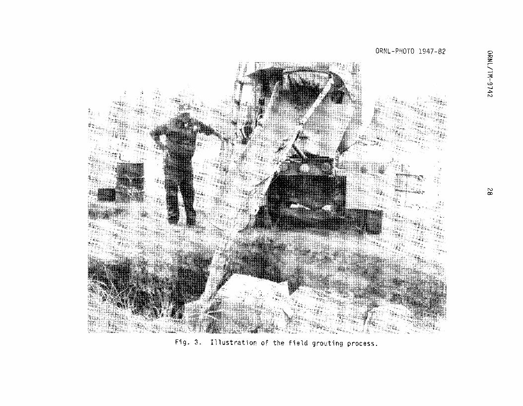
3 I l l u s t r a t i o n of the f i e l d grouting process . . . . . . . . 28
4 Water e levat ions measured i n l ined trench 334 . . . . . . . 34
5 Water e levat ions measured i n l ined trench 330 . . . . . . . 35
6 Water e levat ions measured i n l ined trench 342 . . . . . . . 36
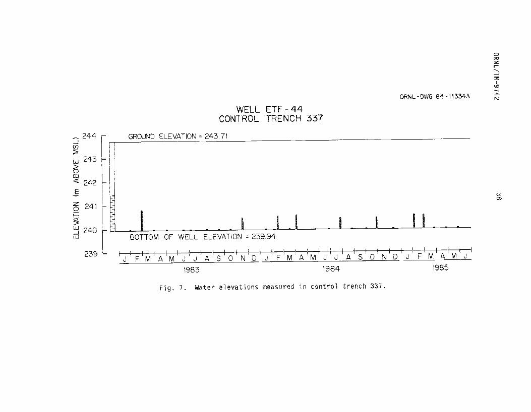
7 Water e levat ions measured i n control trench 337 . . . . . . 38
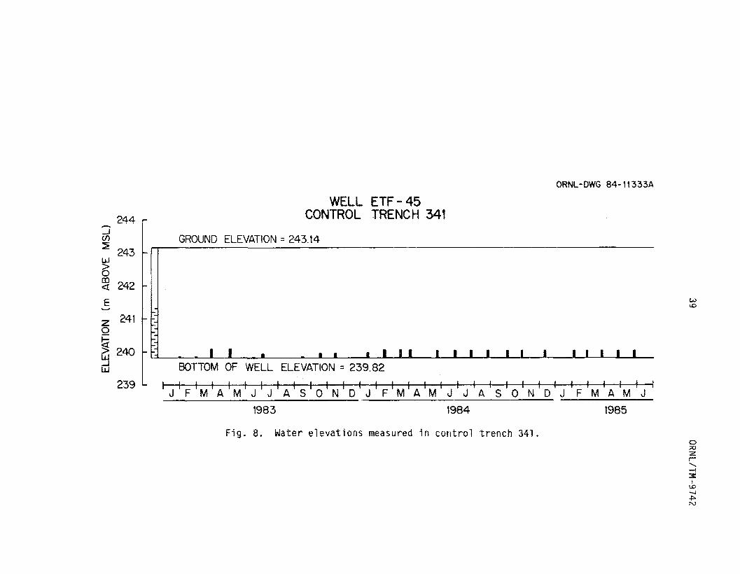
8 Water e levat ions measured i n control trench 341 . . . . . . 39
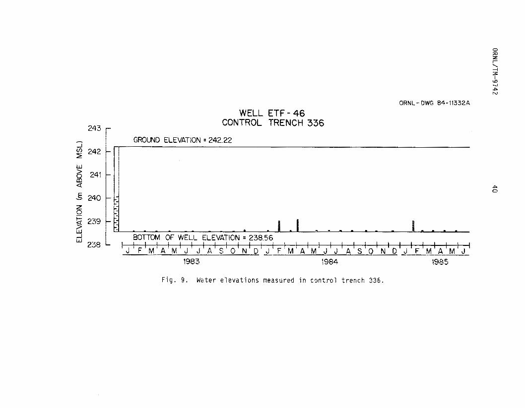
9 Water e levat ions measured i n control trench 336 . . . . . . 40
10
11
1 2
13
14
15
76
1 7
18
Water e levat ions measured i n grouted trenches 339. 335. and 340 . . . . . . . . . . . . . . . . . . . . . . . 43
Water e levat ions d u r i n g drainage o f lined trench 342 . . . 47
Water e levat ions d u r i n g drainage of lined trench 338 . . . 49
Water e levat ions d u r i n g drainage of l ined trench 334 . . . 49
Water e levat ions i n l ined trenches d u r i n g water pump- i n t e s t s . . . . . . . . . . . . . . . . . . . . . . . . . 54
Trench cover subsidence t r ansec t s . . . . . . . . . . . . . 7 2
Subsidence along ETF t r a n s e c t 1 . . . . . . . . . . . . . . 74
Subsidence along ETF t r a n s e c t 2 . . . . . . . . . . . . . . 75
Subsidence along ETF t r ansec t 3 . . . . . . . . . . . . . . 76
V


L I S T OF TABLES
Table
1
2
3
4
5
6
7
El
9
10
11
1 2
1 3
P r o p e r t i e s of p o t e n t i a l t r e n c h l i n e r m a t e r i a l s . . . . . . . 11
Commonly used cement-based and chemical g r o u t s . . . . . . . 1 5
Methods used i n e v a l u a t i n g t h e a b i l i t y o f t h e l i n e r and g r o u t t rea tmen ts t o p r e v e n t water-waste c o n t a c t . . . . . . 31
Summary o f des ign and c o n s t r u c t i o n c h a r a c t e r i s t i c s o f i n t r a t r e n c h m o n i t o r i n g w e l l s . . . . . . . . . . . . . . . . 33
A comparison between h e i g h t s o f s tand ing wa te r observed i n c o n t r o l t renches 337 and 336 and t h e p reced ing 5 days ' r a i n f a l l . . . . . . . . . . . . . . . . . . . . . . 42
Summary o f wa te r d e l i v e r y t o l i n e d t renches 342, 338, and1334 . . . . . . . . . . . . . . . . . . . . . . . . 53
Water e l e v a t i o n s i n f o u r w e l l s su r round ing t r e n c h 342 d u r i n g w a t e r pump-in t e s t s . . . . . . . . . . . . . . . . . 55
Water e l e v a t i o n s i n f o u r w e l l s su r round ing t r e n c h 338 d u r i n g wa te r pump-in t e s t s . . . . . . . . . . . . . . . . . 56
Water e l e v a t i o n s i n f o u r w e l l s su r round ing t r e n c h 334 d u r i n g wa te r pump-in t e s t s . . . . . . . . . . . . . . . . . 57
Comparison o f h y d r a u l i c c o n d u c t i v i t y va lues measured i n t h e g rou ted and c o n t r o l t renches . . . . . . . . . . . . 62
Exper imenta l des ign used f o r t h e g r o u t and l i n e r a g i n g s tudy . . . . . . . . . . . . . . . . . . . . . . . . 67
P r e l i m i n a r y r e s u l t s o f t h e g r o u t and l i n e r a g i n g s tudy . . . 69
Change i n s u r f a c e e l e v a t i o n above l i n e d t renches 334 and 342 between survey 1 (March 1983) and survey 5 ( J u l y 1985) . . . . . . . . . . . , . . . . . . . . . . . 7 7
v i i

ABSTRACT
D A V I S , E . C., and B. P. SPALDING. 1986. Field evaluation of a cement-bentonite g r o u t and a chlorosulfonated polyethylene f ab r i c l i n e r i n hydrologically i so l a t ing low-level radioact ive so l id waste. ORNUTM-9742. Oak Ridge National Laboratory, Oak Ridge, Tennessee. 98 pp,
Applying engineered modifications t o present shallow land burial
p rac t ices i s one method of assuring safe operation and improving
overal l disposal s i t e performance. Two such engineered modifications,
trench l i n i n g and g rou t ing , have been demonstrated and evaluated in the
Shallow Land Burial Technology Task (WBS No. OR 3.5.4.4 A R O N L - W L l 4 )
performed f o r the Department of Energy Low-Level Waste Management
Program. O f t he large number o f l i n e r s and grouts cur ren t ly i n use,
reinforced chlorosulfonated polyethylene (Hypalon ) f ab r i c and a 0
Portland cement-bentonite grout were selected f a r demonstration w i t h i n
a group o f nine 28-m experimental trenches containing compacted 3
low-level waste generated a t the Oak Ridge National Laboratory. This
report descr ibes the treatment se lec t ion process, the l i n e r and g r o u t
( t rench t reatments) development and emplacement techniques, and the
f i e l d monitoring program used t o evaluate l i n e r and grout performance.
Groundwater monitoring has shown t h a t standing water i s present i n a l l
nine experimental trenches ( b o t h t rea ted and untreated); however, depth
of water and water level f luc tua t ion pa t te rns d i f fe red according t o
trench treatment and were minimal i n the case of the grouted t renches.
Both water pump-in and water pump-out t e s t s conducted on the l ined
trenches showed t h a t the or ig ina l goal o f water t igh t l i n e r s was not
achieved and t h a t water was enter ing and leaving these trenches w i t h
i x
each p r e c i p i t a t i o n event. Mater e n t e r i n g i n t o t h e g r o u t e d t renches was
i n h i b i t e d by t h e cement-bentoni te g r o u t b a c k f i l l , as r e f l e c t e d i n t h e
l ower values o f h y d r a u l i c c o n d u c t i v i t i e s t h a t were measured i n these
th ree trenches compared w i t h t hose i n t h e t h r e e c o n t r o l (untreated)
trenches. In examining eng fneer ing p r o p e r t i e s o f t h e g r o u t and l i n e r
aaterial, i t was found t h a t no 5 i g n i f i c a n t change i n l i n e s t e n s i l e
s t r e n g t h or l i n e r puncture r e s i s t a n c e has been observed i n t h e i n i t i a l
1 5 months o f a l i n e r ag ing s tudy, i n d i c a t i n g t h a t t h e r e were no
s h o r t - t e r m changes i n these eng ineer ing prapcrt ies w i t h f i e l d
weather ing. Cover 5iJbSidenCe has n o t occurred ove r t h e grauted o r
c o n t r o l t renches, w h i l e 2 o f %he l i n e d t renches have s e t t l e d 1-10 cm
(2-396 o f t h e t r e n c h depth) i n the f i r s t two years. Based on these
t r e a t m e n t e v a l u a t i o n t e s t s , t h e cement-bentowite g rou ted t renches
appear t o o f f e r t h e h i y h e s t l e v e l of wa te r p r o t e c t i o n campdred t o t h e
HypalonO l i n e d and t h e c o n t r o l trencher;.
X

I . EXECUTIVE S U M ~ A ~ Y
I n 1981, f l e l d exper iments were i n i t i a t e d a t t h e Oak Ridge
N a t i o n a l Labora to ry Engineered Tes t F a c i l i t y ( E T F ) t o demonstrate and
e v a l u a t e two m o d i f i c a t i o n s t o s h a l l o w l a n d b u r i a l o f l o w - l e v e l
r a d i o a c t i v e wastes as c u r r e n t l y p r a c t i c e d . The two m o d i f i c a t i o n s
s e l e c t e d were t r e n c h g r o u t i n g u s i n g a P o r t l a n d cement-bentoni te c l a y
m i x t u r e and t r e n c h l i n i n g u s i n g an impermeable Hypalon@ f a b r l c
l i n i n g m a t e r i a l . Advantages o f t h e g r o u t t rea tmen t were though t t o
i n c l u d e : ( 1 ) t h e a b i l i t y o f t h e g r o u t t o " f i x " t h e waste and
a s s o c i a t e d r a d i o n u c l i d e s w i t h i n t h e c o n f i n e s of t h e t r e n c h , ( 2 ) t h e
tendency o f t h e (grout t o impede wa te r f l o w t h rough t h e waste t renches,
and ( 3 ) t h e s t r u c t u r a l s t r e n g t h o f t h e g r o u t .;upporting t h e t r e n c h s o i l
cove r and p r e v e n t i n g f u t u r e t r e n c h cave r subsidence. Advantages o f t h e
l i n i n g o p e r a t i o n were though t t o i n c l u d e : ( 1 ) t h e r e l a t i v e low c o s t
assoc ia ted w i t h l i n i n g t h e f o u r s ides , top, and bot tom o f a t r e n c h ,
( 2 ) t h e complete hydro ' log ic i s o l a t i o n o f waste con ta ined i n a
w a t e r t i g h t l i n e r , and ( 3 ) t h e a v a i l a b i l i t y o f l i n i n g m a t e r i a l s and
t h e i r common use i n t h e f i e l d o f hazardous waste d i s p o s a l and s to rage .
T h i s r e p o r t summarizes t h e process a f t r e n c h t r e a t m e n t s e l e c t i o n
(Chapter 3 ) . t r e n c h t r e a t m e n t implementat ion i n t h e f i e l d (Chapter 4 ) ,
and t h e p o s t - c o n s t r u c t i o n exper iments used t o e v a l u a t e t h e t rea tmen ts
as improved s h a l l o w l a n d b u r i a l methods (Chapter 5 ) .
A f t e r app rox ima te l y two years o f l a b o r a t o r y and f i e l d t e s t i n g
designed t o e v a l u a t e t h e performance o f t h e g rou ted and l i n e d t renches,
i t was concluded t h a t t h e cement-bentoni te t r e a t m e n t o f f e r e d t h e
ORNL/TM -4 742 2
h i g h e s t degree o f waste i s o l a t i o n and i s t hus recommended over t r e n c h
l i n i n g as desc r ibed i n t h i s r e p o r t . The major drawbacks t o t h e use o f
t h e Hypalon l i n i n g m a t e r i a l were t h e d i f f i c u l t y i n c o n s t r u c t i n g
t h e necessary seams i n t h e f i e l d , t h e leakage o f wa te r b o t h i n t o and
o u t sf t h e l i n e d t renches t h a t has been observed s i n c e l i n e r
i n s t a l l a t i o n , and t h e degree o f cove r subsidence t h a t has occurred
s i n c e t r e n c h c l o s u r e . None o f t hese problems were ahserved w i t h t h e
g rou ted t renches; i n a d d i t i a n , t h e y have e x h i b i t e d a lower
w a s t e - b a c k f i l l h y d r a u l i c c o n d u c t i v i t y t han t h e t h r e e c o n t r o l t renches,
i n d i c a t i n g g r e a t e r p r o t e c t i o n a g a i n s t i n f i l t r a t i n g water . Trench
Q
c l a y s l u r r y ,
nirnal
t r e n c h .
g r o u t i n g , u s i n g an inexpensive P o r t l a n d
i s t hus t h e t r ea tmen t o f cho ice and WQU
developmental work t o be sca led up t o a
cement-bentoni te
d r e q u i r e o n l y rn
f u l l - s i zed waste
ORNL/TM-974 2
2. INTRODUCTION
Shal low l a n d b u r i a l (SLB) i s , i n most cases, an e f f e c t i v e d i s p o s a l
method f o r l o w - l e v e l r a d i o a c t i v e s o l i d waste. The o p e r a t i o n o f SLB
d i s p o s a l areas r e q u i r e s t h e management o f s u r f a c e r u n o f f and
groundwater i n ways t h a t p r e v e n t w a t e r f rom c o n t a c t i n g b u r i e d waste and
p o s s i b l y l e a c h i n g r a d i o n u c l i d e s and t r a n s p o r t i n g them t o u n r e s t r i c t e d
areas. A l though s i t e s e l e c t i o n i s t h e m o s t power fu l t echn ique t o a v o i d
such env i ronmenta l con tamina t ion problems, a l l p r e s e n t and f u t u r e s i t e s
w i l l l i k e l y have e i t h e r (1) subareas w i t h marg ina l geohydro log i ca l
c h a r a c t e r i s t i c s f o r waste d i s p o s a l o r ( 2 ) c lasses o f wastes w i t h a
s u f f i c i e n t i n v e n t o r y o f r a d i o a c t i v i t y t h a t t h e degree o f i s o l a t i o n
p r o v i d e d by t h e g e o l o g i c f o r m a t i o n may n o t p r o v i d e adequate assurance
t h a t s i t e performance o b j e c t i v e s can be met. F o r e i t h e r o f these
s i t u a t i o n s , engineered m o d i f i c a t i o n s o f t hese b u r i a l areas, o r o f t hese
wastes, c o u l d p r o v i d e t h e necessary assurance f o r acceptable s i t e
performance. Two such engineered m o d i f i c a t i o n s , t r e n c h l i n i n g and
t r e n c h g r o u t i n g , have been under i n v e s t i g a t i o n as p a r t o f t h e Shal low
Land B u r i a l Technology Task performed a t Oak Ridge N a t i o n a l Labora to ry
(ORNL) f o r t h e Department o f Energy (DOE) Low-Level Waste Hanagement
Program.
Problems i d e n t i f i e d as p o t e n t i a l l y compromising t h e performance o f
SLB s i t e s i n c l u d e groundwater i n t r u s i o n , t r e n c h cover subsidence and
r e s u l t i n g s u r f a c e r u n o f f i n t r u s i o n , p l a n t and animal i n t r u s i o n , and
r a d i o n u c l i d e m i g r a t i o n t o u n r e s t r i c t e d areas. I n theo ry , e i t h e r
g r o u t i n g o r l i n i n g o f t renches can reduce a l l o f t hese problems.
However, a f i e l d demonstration o f t h e i r effect iveness i s requircd
before these techniques can be advocated as standard p rac t i ce f o r
ex i s t ing or future disposal operations. T h u s , t h e focus of t h i s study
has been on a f i e l d demonstration o f t r e n c h g r o u t i n g and l in ing
techniques t h a t can be used, not a s a remedial measure, but d u r i n g
waste disposal opera%ions a s a possible improvement t o present_
p r a c t i c e s ,
O f t h e many g r o u t s and l i n e r s t h a t a r e commercially ava i l ab le , two
s p e c i f i c treatments were selected f o r demonstration; a Portland
cement-bentonite grout applied a s a trench b a c k f i l l , and an imper
Hypalon@ f a b r i c l i n e r placed i n a trench i n such a way t h a t i t
surrounds t h e waste on a l l four s i d e s , t op , and bottom. F o r e v a l u a t j m
purposes, t h e performances of t hese two trench treatments were compared
w i t h the performance o f untreated trenches typ ica l o f current SLB
disposal operations. This report describes the process used t o s e l e c t
t he cement-bentonite trench grout and t he Hypalon trench l i n e r (Chapter
3 1 , t h e descr ipt ion of t h e i r f i e l d emplacement (Chapter (a ) , and an
evaluation of t h e a b i l i t y of each treatmen% to hydrologically i s o l a t e
t he contained waste (Chapter 5).
In t h i s demonstration, a g r o u t r e f e r s t o a slurry t h a t can flow
i n t o trench void space inherent i n waste-backfill mixture; and, after-
i t has s e t , become impermeable t o water. Because t h e t rench volume i s
mdde impermeable, the probleni~s of water intrusion and re ru l t i n g
radionuclide migration can bc eliminated. In addi t ion, s ince the s e t
g rou t can have subs t an t i a l cohesive s t r eng th , p l an t and an imal
int rusion and trench subsidence can a l s o be eliminated a s long a s t h e
grout i s i n t a c t .

Trench l i n i n g can a l s o a l l e v i a t e many o f t hese same problems. The
cont inuous l i n i n g o f t r e n c h w a l l s , f l o o r , and cove r w i t h an i n h e r e n t l y
impermeable m a t e r i a l w i l l e f f e c t t h e h y d r o l o g i c i s o l a t i o n o f i t s
con ta ined waste f r o m s u r f a c e and groundwater and e1irn.inat.e any
p o t e n t i a l f o r r a d i o n u c l i d e m i g r a t i o n . Such t r e n c h l i n i n g may a l s o
e l i m i n a t e t r e n c h cove r subsidence s i n c e water, t h e cause o f t h e
subsidence, i s o b s t r u c t e d . The r a p i d subsidence d u r i n g t h e adolescence
o f t r e n c h l i f e i s t r i g g e r e d by a water- induced b a c k f i l l c o l l a p s e i n t o
v o i d s between waste packages. By e l i m i n a t i n g wa te r f rom t h e wasle, t h e
t r e n c h l i n e r can e l i m i n a t e b a c k f i l l movement w i t h i n t h e t r e n c h and
t h e r e f o r e r e s u l t i n reduced subsidence. 8y m a i n t a i n i n g compara t i ve l y
d r y c o n d i t i o n s w i t h i n t h e waste, t r e n c h l i n i n g can a l s o i n h i b i t waste
decomposi t ion and g r e a t l y reduce t h e l ong - te rm subsidence o f t renches
caused by t h e degrada t ion o f waste and waste c o n t a i n e r s .
The s i t e s e l e c t e d f o r t h e exper imenta l demonstrat ion o f these two
improved s h a l l o w land b u r i a l p r a c t i c e s i s a 0.3-ha t r a c t o f l a n d
l o c a t e d w i t h i n Solid Waste Storage Area S i x (SWSA 6) a t UROJL.
28-rn exper imen ta l t renches were excavated a t t h e s i t e (known a s t h e
Engineered Tes t F a c i l i t y o r ETF) i n a 3 by 3 m a t r i x w i t h t h r e e t renches
s e l e c t e d f o r l i n i n g , t h r e e s e l e c t e d f o r g r o u t i n g , and t h r e e s e r v i n g as
c o n t r o l s ( u n t r e a t e d t r e n c h e s ) . The ETF has been t h e s u b j e c t o f an
ext.ensive d i s p o s a l s i t e c h a r a c t e r i z a t i o n s tudy (Vaughan e t a l . 1982,
Davis e t a l . 1984, and Newbold and Bogle 1984) and a d e t a i l e d
d e s c r i p t i o n o f t h e exper imen ta l p l a n has been p r e v i o u s l y pub l i shed
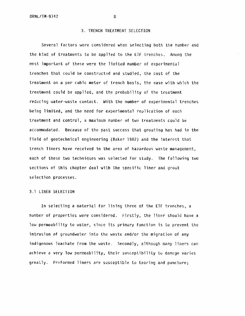
(Boegly and D a v i s 1983). F i g u r e 1 p resen ts a p l a n view s f t h e ETF
Mine 3

ORNL/TM-9742
8 4-16
F i g , 1 . Plan v iew o f t h e ETF s i t e .

7 ORML/lM-9742
study s i t e w i t h i n SWSA 6, showing t h e loca t ions o f t he experimental
t renches , monitoring wel l s , ra in gauge, and sur face water sampling
s t a t i o n s (Parsha l l f lumes).
ORNL/TM-9742 8
3 . TRENCH TREATME
Severa l f a c t o r s were considered when s e l e c t i n g bo th the number and
t h e k i n d o f t rea tmen ts t o be a p p l i e d -Lo t h e ETF t renches .
most. i m p o r t a n t o f these were t h e l i m i t e d number o f exper imenta l
t renches t h a t cou ld be cons t ruc ted and s tud ied , the c o s t o f t h e
t r e a t m e n t on a p e r cub ic meter o f t r e n c h bas i s , t h e ease w i t h which t h e
t rea tmen t cou ld be a p p l i e d , and t h e p r o b a b i l i t y o f t h e t rea tmen t
reduc ing water-waste c o n t a c t . W i th t h e number o f experirneri tal t r e n c h e r
be ing l i m i t e d , and t h e need f o r exper imenta l r e p l i c a t i o n o f each
t r e a t m e n t and c o n t r o l , a maximum number o f two t rea tmen ts cou ld be
Aniong t h e
odated. Because o f t he p a s t success t h a t g r o u t i n g has had i n t h e
f i e l d o f geo techn ica l eng inee r ing (Baker 1982) and t h e i n t e r e s t t h a t
t r e n c h l i n e r s have r e c e i v e d i n t h e area of hazardous waste manage
each o f t hese two techniques was s e l e c t e d f o r s tudy. l h e f o l l o w i n g two
s e c t i o n s o f t h i s chap te r deal w i t h t h e s p e c i f i c l i n e r and g r o u t
s e l e c t i o n processes.
3,1 L INER SELECTION
I n s e l e c t i n g a m a t e r i a l f o r l i n i n g t h r e e o f the ETF t renches, a
number o f p r o p e r t i e s were considered. F i r s t l y , t h e l i n e r should have a
l ow p e r m e a b i l i t y t o water, s i n c e i t s p r imary f u n c t i o n i s t o p reven t t h e
i n t r u s i o n o f groundwater i n t o t h e waste and/or t h e m i g r a t i o n o f any
ind igenous leacha te f rom t h e waste. Secondly, a l t hough many l i n e r s can
achieve a ve ry low p e r m e a b i l i t y , t h e i r s u s c e p t i b i l i t y t o damage v a r i e s
g r e a t l y . Preformed l i n e r s a r e s u s c e p t i b l e t o t e a r i n g and puncture;
9 ORNL/TM-9742
such damage would, o f course, s e r i o u s l y compromise l i n e r performance.
Other t ypes o f l i n e r s , such as cements, aspha l t s , s i l i c a t e s , and
b e n t o n i t e s , a r e s u s c e p t i b l e t o shear ing s t r e s s e s which couad
p o t e n t i a l l y r e s u l t i n breeching, e i t h e r d u r i n g i n s t a l l a t i o n and waste
emplacement o r in t h e l o n g term. Thus, a l l m a t e r i a l s need t o be
considered f o r t h e i r long- term weather ing c h a r a c t e r i s t i c s and
performance under changing s t r e s s e s d u r i n g any p o t e n t i a l waste
subsidence.
f o r a l i n e r t o be e f f e c t i v e , i t must a l s o be capable o f be ing
i n s t a l l e d on a l l su r faces o f a t r e n c h : f l o o r , w a l l s , and t o p ,
B e n t o n i t e , a s p h a l t , and s o i l cement would be d i f f i c u l t m a t e r i a l s f o r
v e r t i c a l t r e n c h w a l l s , because cons ide rab le s t r u c t u r a l suppor t i s
r e q u i r e d d u r i n g t h e i r i n s t a l l a t i o n . Other m a t e r i a l s , such as var-ious
u n r e i n f o r c e d p l a s t i c sheet ing, do n o t have t h e t e n s i l e s t r e n g t h and
b e a r i n g c a p a c i t y r e q u i r e d f o r a cove r m a t e r i a l . I n - s i t u g r o u t i n g o f a
o r s i l i c a t e s , can
as a cove r m a t e r i a l
a s t i c shee t ing . A l l
f i l l i n g , due t o
puncture, t e a r i n g , o r s t r e s s c r a c k i n g . Trench f l o o r s , which bear t h e
w e i g h t o f t h e waste, would be p a r t i c u l a r l y s u s c e p t i b l e t o t h i s t y p e o f
damage. P l a s t i c s h e e t i n g c o u l d be p r o t e c t e d on a t r e n c h f l o o r by
c o v e r i n g w i t h a l a y e r o f b a c k f i l l t o d i s t r i b u t e s t resses . P l a s t i c
m a t e r i a l s can a l s o be l am ina ted w i t h h i g h t e n s i l e s t r e n g t h f a b r i c s ,
y i e l d i n g q u i t e rugged l i n e r s , e.g., Hypalon . 0
t r e n c h f l o o r and w a l l s , e.g.
r e s u l t i n a v e r y e f f e c t i v e 1
s u f f e r t h e same l a c k o f bear
w i t h po l yac ry lam ides
ne r , b u t these g r o u t s
ng c a p a c i t y as does p
l i n e r s c o u l d s u f f e r p o t e n t i a l damage d u r i n g t r e n c h
QRNL/TM--9742 10
Cost i s a c r i t i c a l f a c t o r i n l i n e r s e l e c t i o n , and o b t a i n i n g a
l i n e r w i t h t h e l a r g e s t number o f d e s i r a b l e p r o p e r t i e s i n c u r s t h e
l a r g e s t c o s t s . A summary o f t h e r e l a t i v e c o s t s and t h e performance
p r o p e r t es o f t h e va r ious l i n e r m a t e r i a l s considered i s presented i n
Table 1 The c o s t da ta used t o prepare t h i s t a b l e have come f rom a
number o f sources, i n c l u d i n g Geswein (1975), Fung (19801, and
manu fac tu re rs ' quoted p r i c e s i n 1981. Data f o r t h e p e r m e a b i l i t y and
long- term performance p r o p e r t i e s have a l s o been assembled f rom seve ra l
sources, i n c l u d i n g B u e l t and Barnes (1981), Lee (1974), Kays (1977),
and manu fac tu re rs ' s p e c i f i c a t i o n s f o r t h e i r m a t e r i a l s . An a d d i t i o n a l
c r i t e r i o n f o r l i n e r s e l e c t i o n was added f o r t h i s e v a l u a t i o n : a
judgment as t o t h e eng ineer ing acceptance o f t h e v a r i o u s m a t e r i a l s as
l i n e r s f o r hazardous m a t e r i a l d i s p o s a l . Th i s a t t r i b u t e was ranked
u s i n g t h r e e c a t e g o r i e s : t h e m a t e r i a l i s i n common usage, t h e m a t e r i a l
i s o f proven usage b u t i n f r e q u e n t l y used, o r t h e m a t e r i a l has n o t been
proven f o r l i n e r a p p l i c a t i o n even though i t s p o t e n t i a l f o r use i s h i g h
based on o t h e r eng inee r ing a p p l i c a t i o n s .
*
O f a l l t h e m a t e r i a l s considered i n Table 1, 1.1-mm r e i n f o r c e d 0 c h l o r o s u l f o n a t e d p o l y e t h y l e n e (Hypalon ) f a b r i c was se lec ted . Th is
s e l e c t i o n was based on i t s ve ry low p e r m e a b i l i t y , i t s ruggedness and
long- term s t a b i l i t y , and i t s wide eng ineer ing acceptance. I t s majo r
disadvantage compared w i t h o t h e r l i n e r m a t e r i a l s i s cos t , which
2 c u r r e n t l y runs about $8.30/m f o r m a t e r i a l o n l y . However,
i n s t a l l a t i o n c o s t s f o r Hypalon a r e q u i t e low compared w i t h those f o r
concretes, cements, b e n t o n i t e , and g rou ts , s i n c e t h e f a b r i c has o n l y t o
be u n r o l l e d and lowered i n t o t h e t rench ; i n s t a l l a t i o n cos ts c o u l d be

Table 1. Properties of potential trench liner materials _-
Susceptibility to damagea
Application Permeability During installation Long -term Engi neeri ngc Cost acceptance Bottom Walls Cover Bottom Walls Cover rate cm/s Materia 1
Bentonite 9 .8 kg/m2 10 -5 L N F M L NF M I C
Asphalt membrane
Asphalt concrete
10-6 2.5 mn M M M M M M 1 I
10-7 51 mn L NF L L NF L 1.4 C
Soi 1 cement 10-5
10-10
10-10
10-10
10-10
1 5 c m
1 .7 nml
0.5 mn
0.8 ~NR
0.8 mn
L Nf
M M
M M
M fl
M M
L NF
i L
M M
M M
PI M
1
3
I . 'I 1 . 7
2.4
Butyl rubber
Polyethylene
P V C
Hypa 1 on@
HypalonO + fiber
Ac ry lami de grout
Silicate grout
10-10 1.1 mn 1 L 1 L i 6 I.
10-6 L L M L L H 7
25 L o f 7. 6X/m2 10-5 1 L M L L M 3 N
aDamage susceptibility ratings:
bCost i s expressed as a ratio to cost of bentonite and includes material and labor but not equipment.
CEngineering acceptance ratings: proven for liner applications,
L = low, M = moderate, H = high, NF = not feasible.
C = proven and common practice, I = proven but infrequent practice, N = not
ORN L/TM --9 7 4 2 12
g r e a t e r if e x t e n s i v e f i e l d seams need t o be c ~ n s t r ~ c t e d between sheets
o f Hypcllon. Whereas g r o u t i n g an ORNL waste d i s p o s a l t r e n c h o f t y p i c a l
s i z e ( 3 . 0 Y 1 5 . 2 x 3 . 1 m; W x L x D ) would c o s t about $9,200 f o r
cement-bentoni te g r o u t i n g m a t e r i a s (assuming $1Q8.32/m and 50% v o i d
space), l i n i n g o f t h e same t r e n c h would c o s t dbout $2,000 f o r t h e
Hypalon f a b r i c .
3
U n l i k e g r o u t i n g , where t h e e n t i r e v o i d volume o f buried waste
needs t o be f i l l e d w i t h t h e impermeable g r o u t m a t e r i a l , l i n i n g r e q u i r e s
t h a t o n l y t h e su r faces o f a t r e n c h be covered, so t h a t t h e l a r g e v o i d
volume w i t h i n t h e waste surrounded by t h e l i n e r need n o t be
considered. Grouting cos ts can be c a l c u l a t e d , a lmost e x c l u s i v e l y , on
t h e t r e n c h v o i d vnlume, whereas l i n i n g cos ts depend on the su r face area
o f t h e t o t a l aggregate o f was te o r , mare d i r e c t l y , on t r e n c h
dimensions. Thus, t h e economic comparison of l i n i n g and g r o u t i n g i s
q u i t e dependent on sca le . Max im izd t i on of t h e volume t o su r face area
r d t i o o f t renches leads t o t h e mast c o s t e f f e c t i v e l i n i n g s t r a t e g i e s .
S ince t renches f o r almost a l l r a d i o a c t i v e w a s t e d i s p o s a l a re i r r e g u l a r
hexahedrons, the r e l a t i o n s h i p o f volume t o s u r f a c e areis o f the r e g u l a r
hexahedron ( t h e cube) as a f u n c t i o n o f s c a l e can St? a u s e f u l examp
The r a t i o o f volume t o siirface area o f a ci ibe equals s i d e l e n g t h
d i v i d e d by 6. IRus, as t h e s i d e l e n g t h o f t h i s h y p o t h e t i c a l cub ic
t r e n c h increases, t h e r a t i o o f volume t o s u r f d c e area increases an
e .
l i n e r cos ts p e r u n i t volume o f w a s t e decrease i n d i r e c t p r o p o r t i o n .
A l though m o s t t renches are i r r e g u l a r , rather than r e g u l a r hexahedrons,
such geometr ic c o n s i d e r a t i o n s i n d i c a t e t h a t t h e larger and inore n e a r l y
13 ORNL/TM-9742
cuhic (i.e., equidimensional) the trench, the more economically
attractive lining becomes when compared with grouting.
A s an example o f this scale effect, the volume to surface area
ratio o f the demonstration trenches (3.05 x 3.05 x 3.05 m) used in this
investigation I s 0.51. For actual disposal trenches used at ORNL ( 3 . 0
x 15.2 x 3 . 7 m), this ratio increases to 0.75. For typical trenches at
the Barnwell, South Carolina, facility (i.e., 30.5 x 152 x 6.1 m), this
ratio equals 2.46. Thus, for such large trenches, the economic
comparison (dollars per cubic meter o f waste) o f lining t o grouting
improves by a factor of 4.8 over the smaller trenches used in this
study. Grouting such a large trench would cost approximately
$7,600,000 for materials, whereas lining materials would cost about
$100,000 for the same trench. Assuming a unit disposal cost of
$233/m of waste (USNRC I S S l ) , grouting would add an incremental
$54/m of trench volume or $108/m o f waste (assuming 50% trench
volume utilization); this would correspond to a 46% increase in
disposal costs. Lining, an the other hand, would incur an incremental
cost o f $3,4/m of trench volume or a 3% increase in disposal costs
for the same trench.
3
3 3
3
3.2 GROUT SELECTION
The second engineered modification being demonstrated in this
inwestigation is the grouting o f low-level waste trenches prior to
final cover application. Although the technology is available to
inject grouts to considerable depths by drilling injection wells and
pumping grout under pressure into fracture zones (Blacklock et al.
ORNL/TM-9742
1982, Handy 1979), application to
occur as trenches are being filled
place. Grouting of trenches after
14
ow-level waste disposal will likely
and before the final cover i s in
cover emplacement constitutes a
remedial action, raising additional obstacles, and is not addressed in
th i s demonst ration p t-oj ec t
A successful trench grouting operation consis-ts of adding a grout
slurry to an open trench until all the void space between waste
packages is filled and the waste is completely covered by grout.
hardening of the grout, t h e waste is encased in a rigid mass o f grout,
achieving isoldtion that prevents both sirrface and groundwater
intrusion problems mentioned earlier.
operation, a grout formulation had to be selected based on several
important engineering, economic, and environmental criteria,
including: slurry viscosity, particle size, permeability w h e
control over setting time, minimum phase separation, availability o f
ingredients, cost of materials, strength and stability, and toxicity.
Table 2 summarizes the various cement-based and chemical grouts that
were considered and are commercially available.
After
l o demonstrate such a grouting
Since most grout development work has centered on soil
Stabilization projects, an important classification of grouts i s their
applicability to varying soil permeabilities. Grauts listed in Table 2
have been so classified; they range from the particulate cernent-based
grouts, having application t o sandy and gravelly soils, to more
recently developed chemical grouts, classified as solutions and finding
application t o much l ess permeable materials such as fine sand and
silts. In grouting open low-level waste disposal trenches, the problem
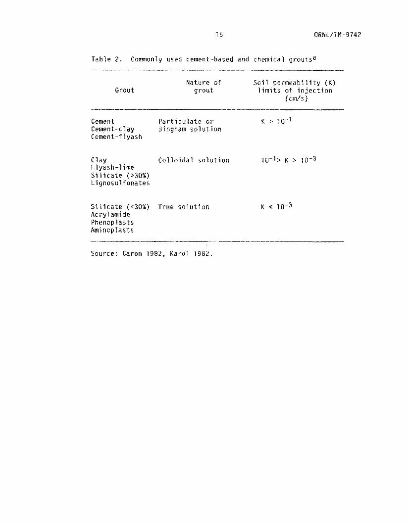
Table 2. Commonly used cement-based and chemical grolutsa
Grout atcrre o f Soil p e r m e a b i l i t y ( K )
grou t l imits of i n j e c t i o n ( c m / s 1
Cement Particulate or K > lo-I Cement-clay Cement-f lyash
Clay Colloidal so l i d t i on Flyash-1 ime S i l i c a t e (>30%) Lignosulfonates
Silicate (<30%) True s o l u t i o n K < 10-3
P h @ n o Q l a ~ t s Ac r y 1 ami de
Aminoplasts
Source: Caron 1982, Karol 19
15
of low soil permeability and resistance t o grout penetration is only a
trivial limitation. M o s t trenches, even if t h e w a s t e is stacked,
r3rely contajn less than 50% void space. This void space i n not made
ltitude o f small, tortuous interstitial pores, as is the case
in soils, b u t rather consists of large crevices and interconnected
fissinrps which o f f e r little resistance t o grout f l o w , As a result,
true solution grouts, or grouts for use w i t h soils o f low per
offer no distinct advantages for this demonstration. In f a c t , because
they also tend t o be more expensive than cemewt-based grouts, they have
a disadvantage f o r this application.
O f t h e many grout mixtures presently in engineering use, a
portland cement-bentonite mixture was selected for demonstration. This
g r o u t satisfies many of t h e design criteria previously listed, such d~
low permeability when set, strength and stability, minimal phase
separation, availability o f ingredients, and control over setting time,
and, perhaps of m o s t importance, it i s in wide use in the engineering
community and is relatively inexpensive. A demonstration o f its
effectiveness in preventing water--related problems in lowlevel waste
disposal trenches would be beneficial, since i t could lead t o immediate
application a t existing disposal sites-
Herndon and Lenahan (1976) examined the economics af a variety of
grouts (materials only) and found that Portland cement mixtures were
relatively inexpensive. In contrast, materials for preparation o f the
colloidal and true solution grouts shown in Table 2 a r e estimated as
being as much as 2 and 7 times as expensive, respectively, as Portland
cement. Only a lime-flyash grout iniyht be mare economically attractive
t han P o r t l a n d cement, because o f t h e l ow p r i c e o f t h e lime and f l y a s h
when purchased i n b u l k . The es t ima ted c o s t ( m a t e r i a l s o n l y ) o f t h e
P o r t l a n d cement-bentoni te g r o u t used i n t h i s demonstrat ion was
($0.41/gal). A c t u a l c o s t o f t h e g r o u t i ~ ~ l u d ~ ~ ~ m i x j n g and d e l i v e r y
Fees was $Q.lb/L ($0.62/gal ) .
B e n t o n i t e (sodium m o n t m o r i l l o n i t e ) , which was adde t o t h e cement,
i s a c o l l o i d a l c l a y commonly mined i n ~ y ~ ~ i ~ ~ and South Dakota and has
l ong been used as a l i g h t - w e i g h t a d d i t i v e t o cement s ' i u r r i e s (Smi th
1 9 7 6 ) . I t s main f u n c t i o n i n e n g i n e e r i n g p r a c t i c e i s t o reduce t h e
w e i g h t o f t h e f i n a l s l u r r y below t h e usual 1.8 kg/L ( 1 5 lb/gal) va lue
common t o n e a t cement s l u r r i e s . When mixed w i t h water , ~ e ~ t o ~ i ~ e
i m p a r t s v i s c o s i t y and n o r m a l l y s w e l l s t o about t e n t i es i t s o r i g i n a l
volume. As an a d i t i v e , u s u a l l y i n c o n c e n t r a t i o n s o f 1 t o 16% by
w e i g h t of t h e cement (Morgan and Dumbauld 1951, 1954; Beach 1961) , i t
inc reases t h e wa te r requi rements, v i s c o s i t y , and t h i c k e n i n g t ime, b u t
decreases t h e d e n s i t y , e a r l y s t r e n g t h , f i n a l s t r e n g t h , and wa te r loss.
I n p r e p a r i n g a g r o u t f o r a p p l i c a t i o n t o l o w - l e v e l waste t renches, none
o f t hese c h a r a c t e r i s t i c s o f b e n t o n i t e a d d i t i o n a r e seen as a problem,
and i n f a c t , t h e r e d u c t i o n i n phase s e p a r a t i o n and t h e s w e l l i n g a r e
d i s t i n c t advantages o f b e n t o n i t e a d d i t i o n .
W i th ASTN Type I P o r t l a n d cement, Oowell 179 b e n t o n i t e , and wa te r
chosen as the t h r e e g r o u t i n g r e d i e n t s , l a b o r a t o r y t e s t i n g t o determine
t h e optimum amounts o f each was i n i t i a t e d . (The b e n t o n i t e manufacturer
i s l i s t e d f o r i d e n t i f i c a t i o n purposes o n l y , and t h e use o f t h i s p r o d u c t
does n o t c o n s t i t u t e an endorsement o r r e c ~ ~ e n ~ a t i o n by ORNL or the
U.S. Department of Energy o r any i m p l i c a t i o n o f s u p e r i o r i t y t o
ORNL/TM-9742 18
c a r r
on a
t h e
o f o t h e r manufacturers . ) A s e r i e s o f bench-scale ba tch rnix ings was
ed o u t u s i n g a 3 . 7 8 4 ( l - g a l ) p o l y e t h y l e n e m i x i n g vessel mounted
v a r i a b l e speed e l e c t r i c motor . Meta l m i x i n g vanes were b o l t e d t o
n t e r i o r o f t h e vessel t o p r o v i d e t h e shear necessary t o comp le te l y
m i x t h e t e s t s l u r r y . Water was f i r s t plat i n t h e m ixe r , f o l l o w e d by a
d r y m i x t u r e o f cement and b e n t o n i t e . The ba tch exper iments v a r i e d t h e
r a t i o o f cement t o wa te r f rom 0.60 t o 0.72 g/ml ( 5 t o 6 l b l g a l ) ,
drawing on p rev ious ORNL h y d r o f r a c t u r e m i x t u r e work (Tamura 1967).
B e n l o n i t e a d d i t i o n , expressed as a percentage o f t h e we igh t o f d r y
cement i n t h e m i x t u r e , was t e s t e d i n t h e range 16 t o 20%. A f t e r m i x i n g
p e r i o d s o f 1 h, s l u r r y v i s c o s i t y , g e l s t r e n g t h , phase separa t i on , and
s e t t i n g t i m e were measured. The s l u r r y m i x t u r e t h a t was judged
acceptable, and thus ready f a r a p p l i c a t i o n t o demonstrat ion t renches,
s p a r t i c u l a r m i x t u r e
and a s l u r r y v i s c o s i t y
o f 24 mPa+s ( 2 4 c p ) + Phase s e p a r a t i o n o f t h i s m i x t u r e was m in ima l ,
and demonstrat ion of g r o u t i n g i n t h r e e 28-m t e s t t renches was
i n i t i a t e d .
3
c o n s i s t e d o f 0.66 g cement/nil wa te r (5.5 lb/gal
(percentage o f we igh t o f d r y cement) added. Th
was observed t o have an 8- t o 12-h s e t t i n g t i m e

19
4 . T R E N C H TREATNENT IMPLEMENTATION
QRN L/T#-974 2
Excavation of t he n i n e experimental trenches ( t renches 34 through
342 of F ig . 1 ) a t the ETF began i n June o f 1981 and was completed
several weeks l a t e r . Pr ior t o t rench excavation, bales o f compacted
low-level waste were being col lected by the ORNL Operations Division
f o r use a t the s i t e . Some of t he f i n a l 219 bales used were stored
on-si te , i n t he open t renches, and others were stored i n another pa r t
of SWSA 6 and then moved t o the ETF when required.
approximately one year a f t e r trench excavation, enough waste had been
generated and baled so t h a t a l l trenches were ready f o r treatment.
By September 1982,
4.1 T R E N C H LINER EMPLACEMENT
Trenches 334, 338, and 342 ( F i g . 1 ) were designated f o r
demonstration of t he disposal technique u s i n g Hypalon@ l i n e r s .
Three 12.19 x 14.0 m sheets of 1.14-mm-thick polyester-reinforced
Hypalon were purchased from Staff Industr ies Inc., Upper Montclair, New
Jersey. ( T h e manufacturer i s l is ted f o r i den t i f i ca t ion purposes only,
and the use of t h i s product does not cons t i t u t e an endorsement o r
recommendation by ORNL o r t he U,S. Department of Energy o r any
implication o f s u p e r i o r i t y t o products of o ther manufacturers.)
sheet was produced w i t h n i n e factory- instal led seams connecting s t r i p s
1.40 rn wide by 12.19 m long.
$8.29/m , along w i t h 18.9 L of HH620 HypalonO Adhesive at $4.49/1
f o r fabr ica t ing f i e l d seams.
Each
T h e Hypalon was purchased a t a cos t o f 2

20
The folded s h e e t s were moved t o a grars-covered area adjoining and
ups lope from t h e nine demonstration trenches on July 12 , 1982. One
sheet was completely unfolded a t t h a t time and required a three-person
crew f o r manipulation, because each sheet weighed approximately
2 2 5 k g , In t h e ea r ly rnorn-lng, p a r t i c u l a r l y during Foggy pes-iods before
sunl ight could warm the black Hypalon, i t exhibited considerable
r e s i s t ance t o deformation (unfolding) . After be ing exposed t o d i r e c t
sunl ight f o r l e s s than 1 h , the Mypalon became very p l i a b l e and t oo h o t
t a handle without gloves. The intense heatiny of t h e Hypalon caused by
the d i r e c t sunl ight f requent ly led t o some int ra-sheet bonding of fo lds
i n t he Hypalon. Presumably, th i s was due t u some residual solvent i n
t he factory seams escaping under the heat and e f f ec t ing some Hypalon t o
Hypalon bonding of the fo lds . Such bonded f o l d s werc usually
r e l a t i v e l y easy t o separate by pull ing the t w o bsiaded sect ions a p a r t .
Midafternoon sun caused such in tense heating t h a t any grass
underlying the Hypalon was heat k i l l e d w i t h several minutes o f
covering.
by u s i n g an ordinary paper s c i s s o r s t o c r ea t e smaller 8 . 4 x 12,19 m
sheet \ . . Each sheet was folded over on i t s e l f w i t h t h e factory seams
running p a r a l l e l t o t he d i r ec t ion o f f a ld ing , r e su l t i ng i n ia two-ply
8.4 x 6.10 m shee t . Each of t h e 6.10 m s i d e s was sealed with adhesive
from the folding point f o r 3 distance o f approximately 3 m.
manufacturer6s recommendations f o r the appl icat ion of f i e l d seams w e r e
followed. Adhesive was applied w i t h a p a i n t brush t o a 15-cm-wide edge
on each surface which rested on a vosd uwderlayment; t he endr of each
seam were weighted down w i t h lead b r i c k s or concrete b l o c k s , and the
Each o f t he th ree 74.Q x 12.19 m flypalon shee ts was t r immed
The
21 ORNUTM-9742
seam was r o l l e d t o e f f e c t t h e r e q u i r e d pressure f o r good adhesion.
F i e l d seaming was always performed i n d i r e c t s u n l i g h t when t h e f a b r i c
was very h o t t o the touch - w e l l above t h e 38°C manufac turer ' s
recommended temperature. Care was a l s o exer ted t h a t sur faces were
c lean b e f o r e s e a l i n g and t h a t a i r bubbles and w r i n k l e s were n o t p resent
i n t h e seam.
r e s u l t e d i n apparent w r i n k l e s w i t h i n t h e seam, i t was p u l l e d a p a r t
b e f o r e t h e adhesive d r i e d ; adhesive was r e a p p l i e d and t h e seaming
process repeated. The seam adhesion was judged complete when the two
sur faces cou ld no t be p u l l e d a p a r t w i t h v igorous t u g g i n g by one person
( i . e . , approx imate ly 35 kg t e a r s t r e n g t h ) .
Occas iona l l y , when t h e f i e l d seam g o t misa l igned, whic.h
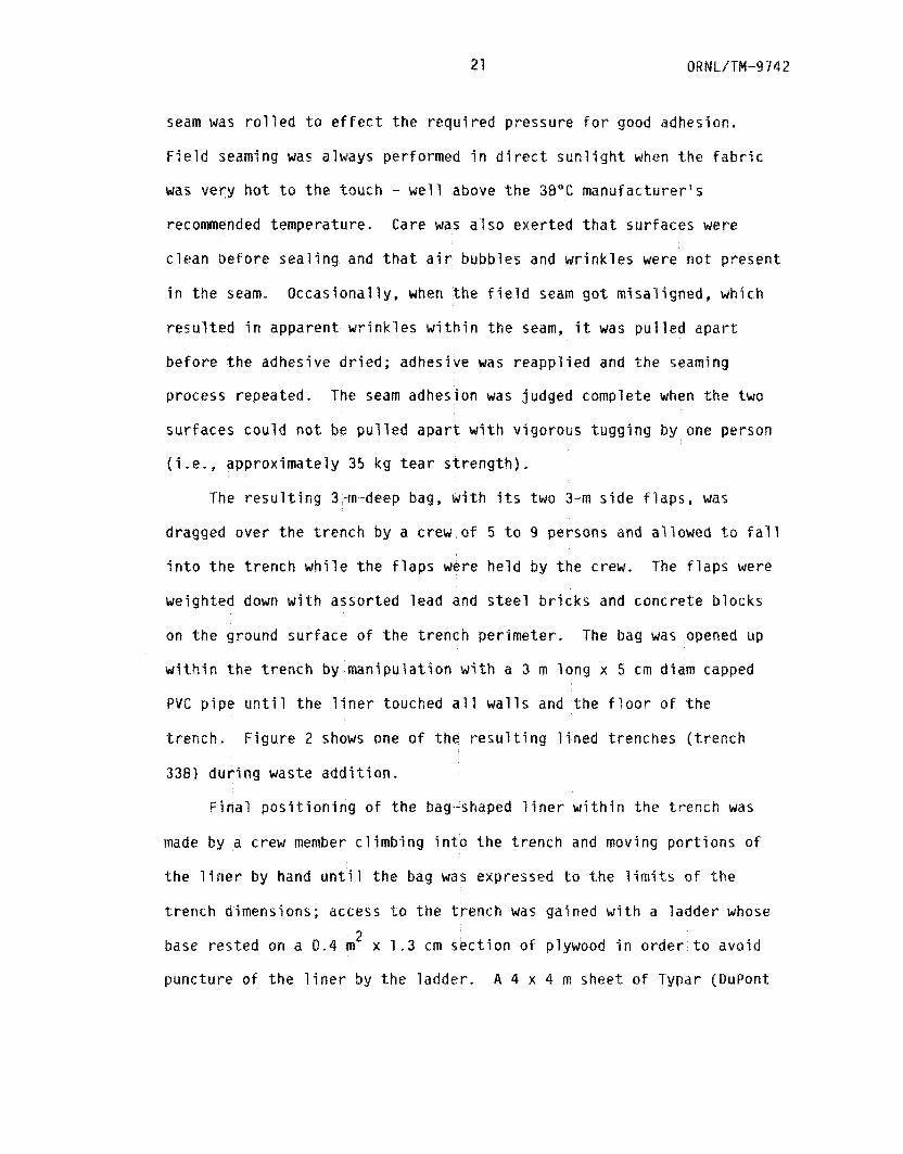
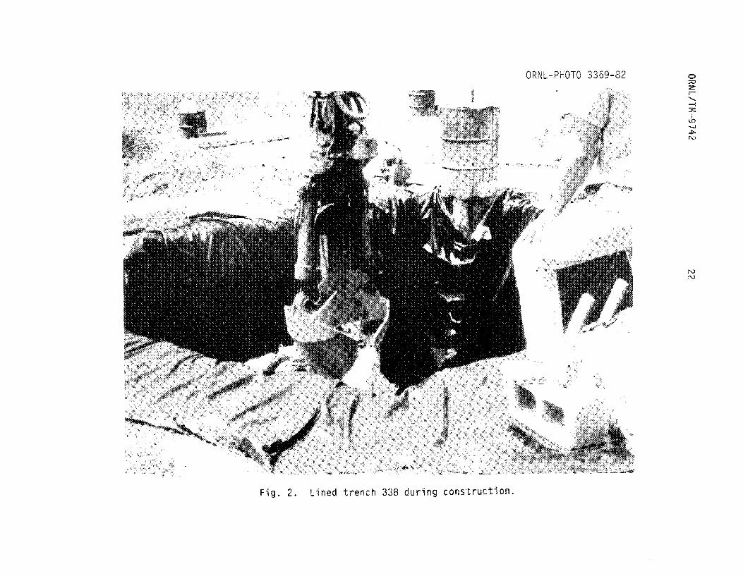
The r e s u l t i n g 3-m-deep bag, w i t h i t s two 3-m s i d e f l a p s , was
dragged over t h e t r e n c h by a crew o f 5 t o 9 persons and a l lowed t o f a l l
i n t o the t r e n c h w h i l e t h e f l a p s were h e l d by t h e crew, The f l a p s were
weighted down w i t h assor ted lead and s t e e l b r i c k s and concre te b locks
on t h e ground su r face o f t h e t r e n c h pe r ime te r . The bag was opened up
w i t h i n t h e t r e n c h by m a n i p u l a t i o n w i t h a 3 m l ong x 5 cm diam capped
PVC p i p e u n t i l t h e l i n e r touched a l l w a l l s and t h e f l o o r o f the
t r ench . F i g u r e 2 shows one o f t h e r e s u l t i n g l i n e d t renches ( t r e n c h
338) d u r l n g waste a d d i t i o n .
Fina'l p o s i t i o n i n g o f t h e bag-shaped l i n e r w i t h i n t h e t r e n c h was
made by a crew member c l i m b i n g i n t o t h e t r e n c h and moving p o r t i o n s o f
t h e l i n e r by hand u n t i l t h e bag was expressed t o t h e limits o f the
t r e n c h dimensions; access t o the t r e n c h was gained w i t h a l adder whose
base r e s t e d on a 0.4 rn x 1.3 cm s e c t i o n o f plywood i n o rde r t o avo id
punc ture o f t h e l i n e r by t h e ladder . A 4 x 4 m sheet o f Typar (DuPont
2
OKNL/TH -9742
21.
23 0 R N LITM -9 7 4 2
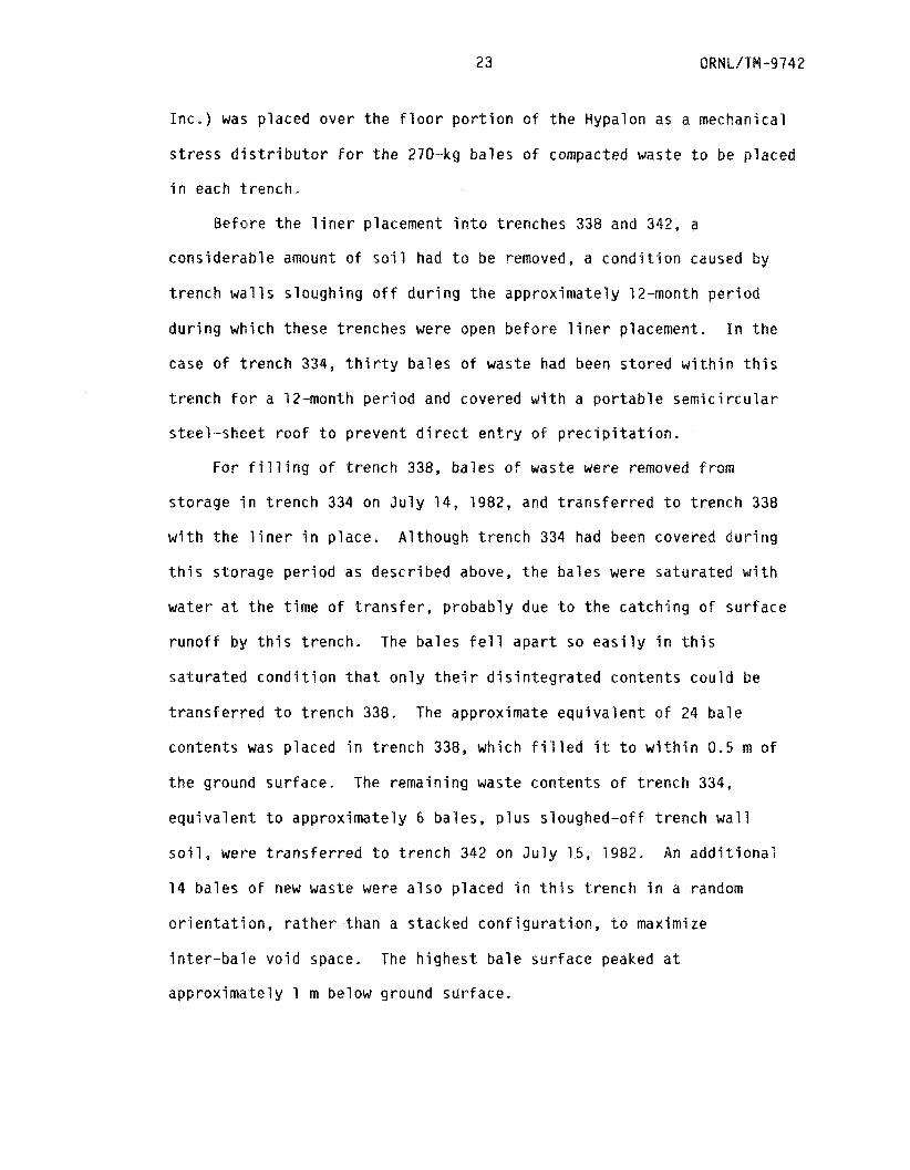
I n c . ) was p laced o v e r t h e f l o o r p o r t i o n o f t h e Hypalon as a mechanical
s t r e s s d i s t r i b u t o r f o r t h e 270-kg ba les o f compacted waste t o be placed
i n each t rench .
Be fo re t h e l i n e r placement i n t o t renches 338 and 342, a
c o n s i d e r a b l e amount o f s o i l had t o be removed, a c o n d i t i o n caused by
t r e n c h w a l l s s lough ing o f f d u r i n g t h e approx ima te l y 12-month p e r i o d
d u r i n g which these t renches were open b e f o r e l i n e r placement. I n t h e
case o f t.rench 334, t h i r t y ba les o f waste had been s t o r e d w i t h i n t h i s
t r e n c h f o r a 12-month p e r i o d and covered w i t h a p o r t a b l e s e m i c i r c u l a r
s t e e l - s h e e t r o o f t o p r e v e n t d i r e c t e n t r y o f p r e c i p i t a t i o n .
F o r f i l l i n g o f t r e n c h 338, bales o f waste were removed fram
s to rage i n t r e n c h 334 on J u l y 14, 1982, and t r a n s f e r r e d t o t r e n c h 338
w i t h t h e l i n e r i n p l a c e . A l though t r e n c h 334 had been covered d u r i n g
t h i s s to rage p e r i o d as desc r ibed above, t h e b a l e s were s a t u r a t e d w i t h
wa te r a t t h e t i m e o f t r a n s f e r , p r o b a b l y due t o t h e c a t c h i n g o f s u r f a c e
r u n o f f by t h i s t r e n c h . The ba les f e l l a p a r t so e a s i l y i n t h i s
s a t u r a t e d c o n d i t i o n t h a t o n l y t h e i r d i s i n t e g r a t e d con ten ts cou ld be
t r a n s f e r r e d t o t r e n c h 338. The approximate e q u i v a l e n t o f 24 b a l e
con ten ts was p laced i n t r e n c h 338, which f i l l e d i t t o w i t h i n 0.5 m o f
t h e ground su r face . The remain ing waste con ten ts o f t r e n c h 334,
e q u i v a l e n t t o app rox ima te l y 6 ba les, p l u s s loughed-of f t r e n c h w a l l
so-il, Mere t r a n s f e r r e d t o t r e n c h 342 on July 15, 1982. An a d d i t i o n a l
14 b a l e s o f new waste were a l s o p laced i n t h i s t r e n c h i n a random
o r i e n t a t i o n , r a t h e r than a s tacked c o n f i g u r a t i o n , t o maximize
i n t e r - b a l e v o i d space. The h i g h e s t b a l e s u r f a c e peaked a t
app rox ima te l y 1 m below ground su r face .
24 ORML/TM -9 742
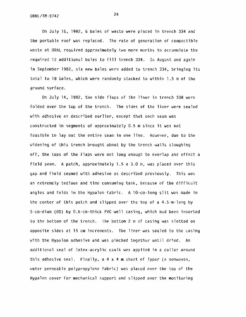
Qn J u l y 16, 1982, 6 ba les o f waste were p laced i n t r e n c h 334 and
t h e p o r t a b l e r o o f was rep laced. The r a t e o f g e n e r a t i o n o f compact ib le
waste a t ORNL r e q u i r e d approx ima te l y two more irmnths t o accuiriulate t h e
r e q u i r e d 1 2 a d d i t i o n a l ba les t o F i l l t r e n c h 334. In August and aga in
i n September 1982, s i x new ba les were added t o t r e n c h 334, b r i n g i n g i t s
t o t a l t o 18 ba les , which were randomly stacked t o w i t h i n 1.5 m o f t h e
ground su r face .
On J u l y 14, 1982, t h e s i d e f l a p s o f t h e l i n e r i n t r e n c h 338 were
f o l d e d ove r t h e t o p o f t h e t r e n c h . The s ides o f t h e l i n e r were sealed
w i t h adhesive as desc r ibed e a r l i e r , except t h a t each seam was
cons t ruc ted i n segments o f approx ima te l y 0.5 m s i n c e i t was n o t
f e a s i b l e t o l a y o u t t h e e n t i r e seam i n one l i n e . However, due t o t h e
wldening o f t h i s t r e n c h b rough t about by t h e t r e n c h walls s lough ing
o f f , t h e tops o f t h e f l a p s were n o t l o n g enough t o o v e r l a p and e f f e c t a
f i e l d seam. A patch, app rox ima te l y 1 .5 x 3.0 m, was p laced ove r t h i s
gap and f i e l d seamed w i t h adhesive as desc r ibed p r e v i o u s l y . Th io was
an ex t reme ly t e d i o u s and t i m e consuming task , because o f t h e d i f f i c u l t
angles and f o l d s i n t h e Hypalon f a b r i c . A 10-cm-long s l i t was made i n
t h e c e n t e r o f t h i s pa tch and s l i p p e d ove r t h e t o p o f a 4.5-m-long by
5-cm-diarn (OD) by O,6-crn-thick P V C w e l l cas ing, which had been i n s e r t e d
t o t h e bot tom o f t h e t r e n c h . The bat tom 2 rn o f cas ing was s l o t t e d on
o p p o s i t e s i d e s a t 1 5 cm increments. The l i n e r was sealed t o t h e cas ing
w i t h t h e Hypalon adhesive and was pinched t o g e t h e r u n t i l d r i e d . An
a d d i t i o n a l seal o f l a t e x - a c r y l i c c a u l k was a p p l i e d i n a c o l l a r around
t h i s adhesive s e a l . F i n a l l y , a 4 x 4 rn sheet o f Typar (a nonwoven,
wa te r permeable po l yp ropy lene f a b r i c ) was p laced ove r the t o p o f t h e
Hypalon cove r f o r mechanical suppor t and s l i p p e d ove r t h e m o n i t o r i n g

25 ORNUTM-9742
, whlch passed th rough a smal l s l i t i n t h e Typar. Thus,
t rea tmen t o f t r e n c h 338 was completed.
On J u l y 15, 7982, the s i d e f l a p s O F t h e 3iner i n t r e n c h 342 were
f o l d e d over and sealed a s desc r ibed above. Again these f l a p s were t o o
s h o r t t o be over lapped, and a p a t c h was f a b r i c a t e d as desc r ibed above.
A m o n i t o r i n g w e l l was emplaced as desc r ibed above, b u t no Typar cove r
was used an t h i s t r e n c h .
On October 15, 1982, t h e c l o s u r e o f t h e t h i r d l i n e d t r e n c h ( t r e n c h
334) was e f f e c t e d , Rather than s e a l i n g t h e s i d e f l a p s t o g e t h e r w i t h
adhesive as was done w i t h t renches 338 and 342, an unsealed Hypalon
r o o f was cons t ruc ted . The Hypalon bag ' s s de f l a p s were f o l d e d ove r
each o t h e r in such a way t h a t a l l f a b r i c s oped downward f rom t h e
c e n t e r o f t h e t r e n c h where t h e m o n i t o r i n g w e l l was p laced. A n
a d d i t i o n a l p i e c e o f Hypalon (4.5 x 4.5 m), w i t h a I O - c m s l i t t o f i t
o v e r t h e m o n i t o r i n g w e l l cas ing, was draped o v e r t h e t o p o f t h e
f o l d e d - i n f l a p s , and t h e edges were tucked between t h e Hypalon bag and
t h e t r e n c h s i d e w a l l s i n such a way t h a t a cont inuous downward s l o p e was
achieved, d r a i n i n g t o t h e t r e n c h w a l l s i n a17 d i r e c t i o n s . A Typar
cove r was p laced o v e r t h i s Hypalon r o o f as desc r ibed above, and t h e
Hypalon was sealed t o t h e w e l l cas ing. A t t h a t t i m e t h e t r e n c h had
approx ima te l y 60 cm o f s t a n d i n g water ; a l t hough a p o r t a b l e r o o f had
been p laced o v e r t h e t r e n c h f o r t h e 3 months t h a t t h e l i n e r had
remained open, a ~ ~ a r ~ ~ ~ l ~ Some s u r f a c e r u n o f f had been caught by t h e
t r e n c h . T h i s unsealed ~ y ~ ~ l o ~ cove r should p r o v i d e a good t e s t o f
whether cont inuous three-d imensional s e a l i n g I s r e q u i r e d f o r e f f e c t i v e
l i n i n g ~f trenches. If cundition.; -"in t h e t o p one t o two meters o f t h e
ORNL/TM-9742 26
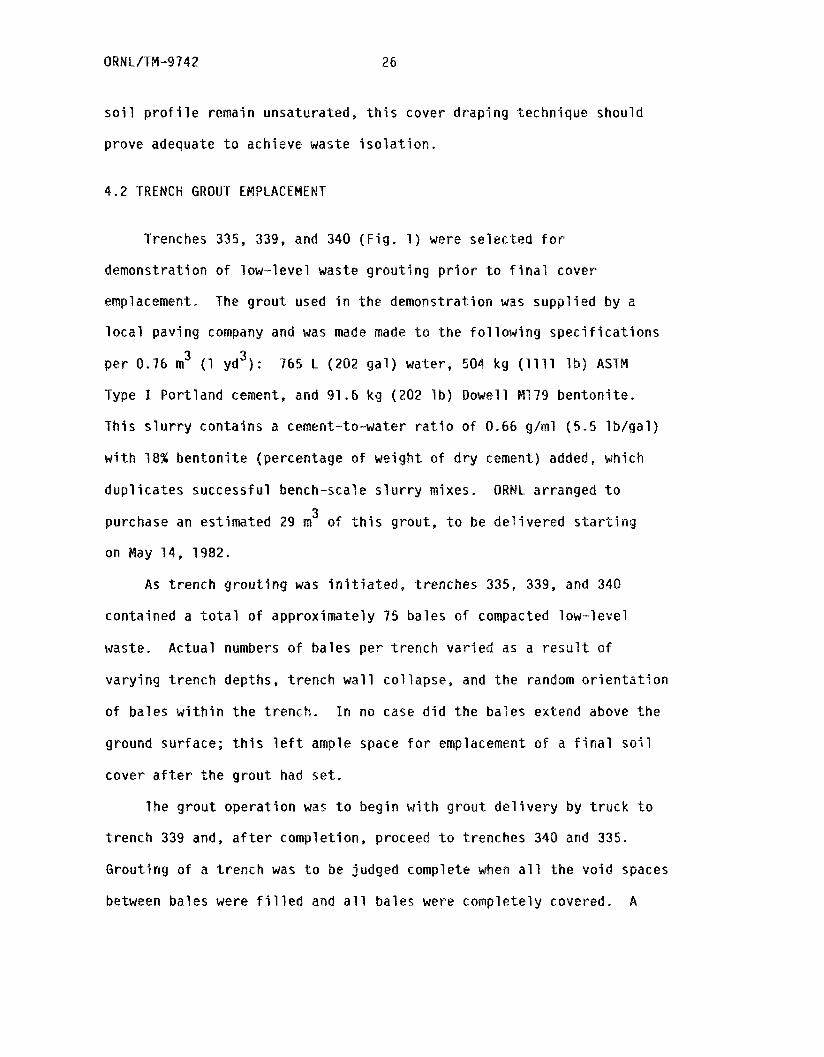
soi l p r o f i l e remain unsaturated, t h i s cover draping technique should
prove adequate t o achieve waste i so l a t ion .
4 . 2 TRENCH GROUT EMPLACEMENT
Trenches 335, 339, and 340 ( F i g . 1 ) were selected f o r
demonstration of low-level waste grouting p r io r t o f i n a l cover
emplacement. The grout used i n the demonstration was supplied by a
local p a v i n g company and was made made t o the following spec i f ica t ions 3 per 0.76 m (1 yd3) : 765 L ( 2 0 2 g a l ) water, 504 kg (1111 l b ) ASTW
Type I Portland cement, and 91.6 kg (202 I b ) Dowel1 Ma79 bentonite.
This slurry contains a cement-to-water r a t i o of 0 .66 g/ml (5,5 lb /ga l )
w i t h 18% bentonite (percentage o f weight o f d r y cement) added, which
dupl icates successful bench-scale slurry mixes. QRNL arranged t o
purchase an estimated 29 m of t h i s g r o u t , t o be delivered s t a r t i n g
on May 1 4 , 1982.
3
A s trench grouting was i n i t i a t e d , trenches 335, 339, and 340
contained a t o t a l of approximately 75 bales o f compacted low-level
waste. Actual numbers of bales per trench varied as a resu l t o f
varying trench depths, trench wall col lapse, and the random or ien ta t ion
of bales w i t h i n t h e trench. In no case d i d t he bales extend above the
ground surface; t h i s l e f t ample space f o r emplacement of a f i n a l s o i l
cover a f t e r the g r o u t had s e t .
The grout operation was t o begin w i t h grout del ivery by truck t o
trench 339 and, a f t e r completion, proceed t o trenches 340 and 335.
Grouting o f a trench was t o be judged complete when a l l the void spaces
between bales were f i l l e d and a l l bales were completely covered. A
27 ORNL/TM-9742
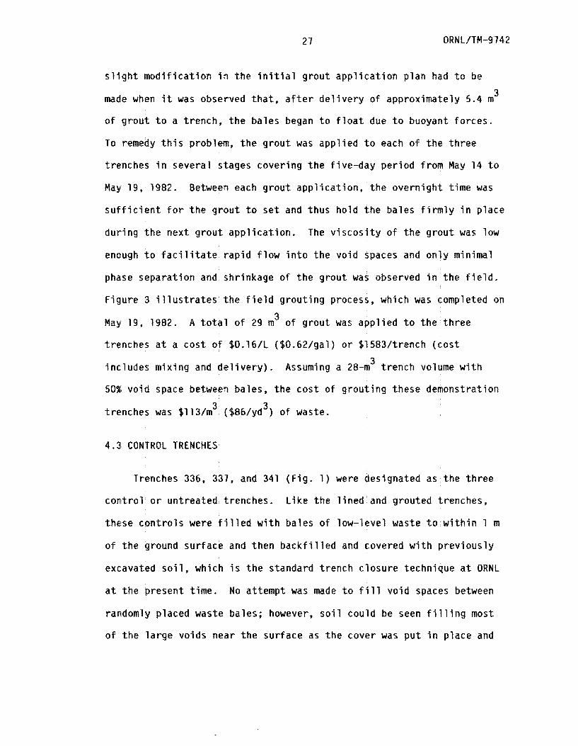
s l i g h t modif icat ion i n t h e i n i t i a l g r o u t appl icat ion plan had t o be
made when i t was observed t h a t , a f t e r del ivery o f approximately 5.4 m 3
o f grout t o a t rench, the bales began t o f l o a t due t o buoyant forces .
To remedy th i s problem, the grout was applied t o each of t h e three
trenches i n several stages covering the f ive-day period from May 14 t o
May 19, 1982. Between each grout appl ica t ion , the overnight time was
s u f f i c i e n t f o r the g r o u t t o set and t h u s hold the bales firmly i n place
d u r i n g the next grout appl icat ion.
enough t o f a c i l i t a t e r ap id f low i n t o the void spaces and only minimal
phase separation and shrinkage o f the grout was observed i n the f i e l d .
Figure 3 i l l u s t r a t e s the f i e l d g r o u t i n g process, which was completed on
The v i scos i ty o f the g r o u t was low
May 19* 1982.
trenches a t a cos t of $0.16/L ($0.62/gal) o r $1583/trench ( c o s t
A t o t a l of 29 m' of g r o u t was applied t o the three
3 includes m i x i n g and de l ive ry ) . Assuming a 28-m trench volume w i t h
50% void space between ba les , the cost of g r o u t i n g these demonstration
trenches was $113/m ($86/yd ) of waste. 3 3
4 . 3 CONTROL TRENCHES
Trenches 336, 337, and 341 (Fig. 1 ) were designated as t h e three
control o r untreated trenches. Like the l ined and grouted trenches,
these cont ro ls were f i l l e d w i t h bales of low-level waste t o w i t h i n 1 m
of the ground surface and t h e n backfi l led and covered w i t h previously
excavated s o i l , w h i c h i s the standard trench closure technique a t ORNL
a t the present time. No attempt was made t o f i l l vo id spaces between
randomly placed waste bales; however, s o i l could be seen f i l l i n g most
of the la rge voids near the surface a s t h e cover was p u t i n place and
28
29 ORNL/PM-9742
compacted. As s t a t e d i n t h e i n t r o d u c t i o n , t h e purpose o f c o n s t r u c t i n g
these t h r e e c o n t r o l t renches was f o r comparison, g i v i n g some mechanism
f o r e v a l u a t i n g s i m i l a r t e s t s performed on the grou ted and l i n e d
t renches .
To c l o s e t h e n i n e exper imen ta l t renches, a 0.3- t o 0.6-m s o i l
cove r was a p p l i e d t o t h e t o p o f each t r e n c h and compacted by r e p e a t e d l y
r o l l i n g a v e r t h e s o i l w i t h a smal l backhoe. In t h i s manner t h e
demons t ra t i on s i t e was r e t u r n e d t o near o r i g i n a l s u r f a c e con tou r , and
t h e s i t e has remained i n t h i s s t a t e t o t h e p r e s e n t t i m e . A d d i t i o n a l
s o i l was b rough t t o t h e s i t e i n p r e p a r a t i o n f o r f i n a l l e v e l i n g and
seeding, which marked t h e comp le t i on o f s i t e c o n s t r u c t i o n ( t r e n c h
t r e a t m e n t ) and t h e beg inn ing o f groundwater m o n i t o r i n g and t r e n c h cove r
subsidence s t u d i e s .
30
5 . TRENCH TREATMENT EVALUATION
Evaluation of the two trench treatments employed a t the ETF
centered on their ability to keep the w a s t e dry and t o remain intact
for an extended t i m e period. A total o f s i x t e s t s were conducted to
examine these two criteria (Table 3 ) ; four dealing with water-waste
contact, one dealing with strength and durability o f materials, and one
addressing the question o f trench cover subsidence. I n some cases the
results of a particular test were evaluated between the th ree c lasses
of trenches (lined, grouted, and control). However, the water pump-~ut
and pump-in tests applied only t o the lined t renches and would have
little o r no meaning if applied to grouted o r control trenches.
Similarly, the hydraulic conductivity tests did not apply to the lined
trenches, and the strength and durability tests bid nat apply t o the
control trenches. Table 3 su arimes each o f the s i x tests used t o
evaluate t h e performance o f t h e ETF trenches and indicates t o w h i c h
class of trenches each test applies.
5.1 PRESENCE aF WATER IN INTRATREMCH WELLS
An obvious indicator of water-waste interaction in disposal
trenches is the presence BT absence of standing water in intratsench
wells. For purposes of a survey of such standing water, wells were
placed in each o f the nine experime t a l trenches at the ESF. Well
construction techniques were s o ~ e ~ h ~ t different between trench
treatments and are su rizeod as follows. Wells E'IF-41 , -42, and -43
were placed in lined trenches 334, 338, and 342, respectively, a t the
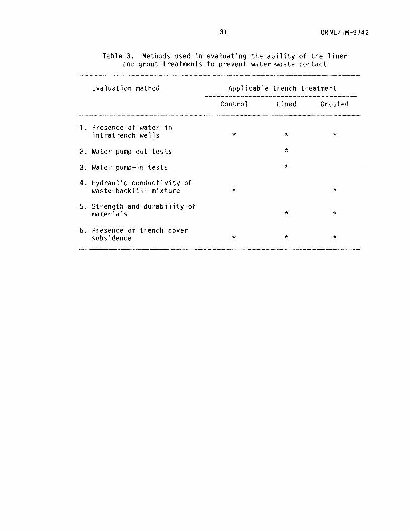
Table 3. Methods used in evaluating the ability o f the liner and grout treatments to prevent water-waste contact
1. Presence o f water i n intratrench wells
2. Water pump-out tests
3 , Water pump-in tests
4. Hydraulic conductivity o f waste-backfill mixture
5, Strength and durability of ma teri a 1 s
6.. Presence o f trench cover subsidence
*
*
*
* JC
* *
*
* *
* *
OR& L/TW -9 7 4 2 32
t i m e t h e waste was be ing p laced i n t h e t renches . A smal l s l i t war made
i n t h e Hypalon cover t o accommodate t h e 5-crrs P V C cas ing, and t h e
Hypalon wa5 sealed t o t h e w e l l cas ing as desc r ibed i n S e c t i o n 4.1.
L ikewise, w e l l s Elk--44, -45, and - 4 6 were l o c a t e d i n c o n t r o l t renches
337, 341, and 336, r e s p e c t i v e l y , as t h e w a s t e %$as be ing loaded i n t h e
t renches M o n i t o r i n g w e l l s were bored, w i t h an auger, i n g rou ted
trenches 349 ( w e l l s E I F 47 and --48), 335 ( w e l l s ETF- -49 and -50), and
339 (we1 s ETF-57 and -52) seve ra l month5 a f t e r t h e f i n a l s o i l cover
had been a p p l i e d , t hus g i v i n g t h e g r o u t ample t i m e t o harden. I f well
casings had been p laced i n these t renches prior t o t rea tmen t , t h e y
would l i k e l y have been f i l l e d w i t h g r o u t and o f no va lue f o r m o n i t o r i n g
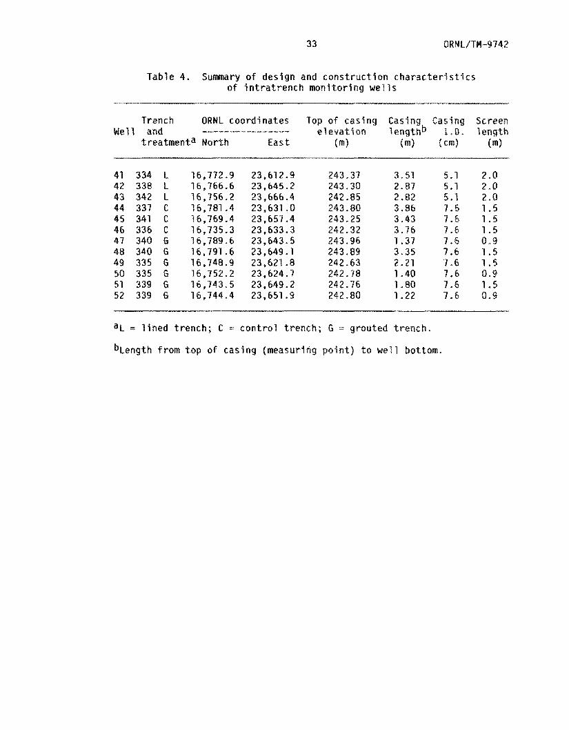
wa te r l e v e l s . 'Iable 4 summarires t h e c h a r a c t e r i s t i c s o f t h e 12
i n t r a t r e n c h m o n i t o r i n g w e l l s .
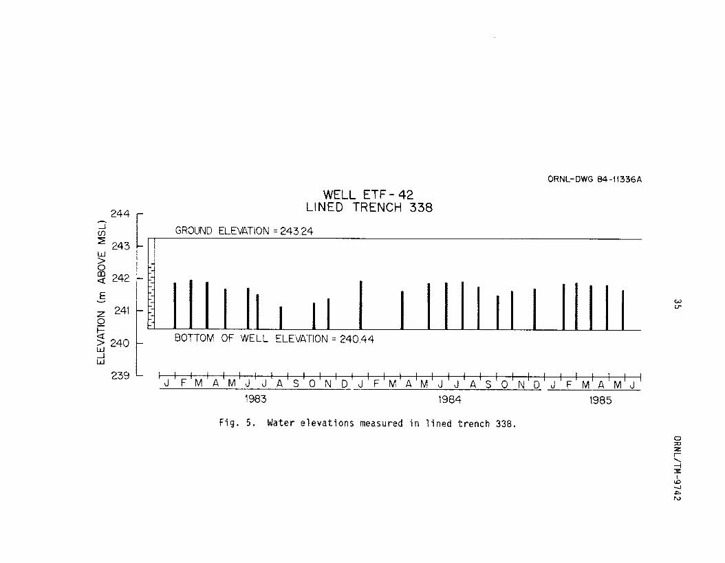
To m o n i t o r f o r wa te r i n these i n t r a t r e n c h w e l l s , t h e depth t o
wa te r was measured p e r i o d i c a l l y f o r 29 months, beg inn ing i n January
1983. F igu res 4 th rough 6 summarize t h e r e s u l t s s f t h i s wate r
m o n i t o r i n g program f o r t h e t h r e e l i n e d t renches. As mentioned i n
S e c t i o n 4.1, wa te r was v i s i b l e i n t r e n c h 334 b e f o r e the Hypalon cove r
was i n s t a l l e d and t h e t r e n c h was c losed . This water , and any water i n
t h e o t h e r two l i n e d t renches, was presumably f rom su r face i n f i l t r a t i o n
d u r i n g t h e t i m e p e r i o d between l i n e r emplacement and cove r emplacement,
w h i l e t h e l i n e d t r e n c h was open and be ing f i l l e d . F igu res 4 through 6
i n d i c a t e t h a t , a f t e r t r e n c h c l o s u r e , w a t e r has remained i n these t h r e e
l i n e d t renches and has e x h i b i t e d f l u c t u a t i n q l e v e l s th roughou t t h e
?!J-n-ionth m o n i t o r i n g p e r i o d . l h i s f l u c t u a t i o n i n i n t r a t r e n c h wa te r i s
m o s t pronounced i n t r e n c h 338 ( F i g . 5 ) which shows a c h a r a c t e r i s t i c
33
T a b l e 4. Sumnary o f design and const ruct ion c h a r a c t e r i s t i c s o f i n t r a t r e n c h moni tor ing wells
Trench ORNL coordinates Tap of casing Casing Casing Screen e l e v a t i o n lengthb X + D . ~ ~ n ¶ ~ ~ __-----_______-- Well and
t rea tmenta Nor th E a s t (m) (m) (cm) (m)
41 334 L 16,772.9 23,612.9 42 338 L 16,766.6 23,645.2 43 342 L 16,156.2 23,666.4 44 337 C 16,781.4 23,631.0 45 341 C 16,769.4 23,657.4 46 336 C 16,735.3 23,633.3 47 340 G 14,789.6 23,643.5 48 348 G 18,797.6 23,649.1 49 335 G 16,740.9 23,621.8 50 335 G 16,752.2 23,624.7 51 339 G 16,743.5 23,649.2 52 339 G 16,744.4 23,651.9
243.37 243 30 242.85 243.80 243 e 25 242.32 243.96 243 * 89 242.63 242.78 242.76 242.80
3.51 5.1 2.8 2.87 5.1 2.0 2.82 5.1 2.0 3.86 9 . 5 1.5 3 * 4 3 7.6 1.5 3 . 7 6 7.6 1.5 1.37 3.35 2.21 1.40 1.80 7.6 1.5 1.22 7.4 8.9
aL = l i n e d t rench; C = c o n t r o l t rench; G = grouted t r e n c h .
bLength f rom t o p o f casing (measurlng p o i n t ) t o we71 bottom.

34
I I I
I I
I -r--r- I........
35 QRHL/Tt.4-9 742
a
?2 rD
m
c
I
8 3
z a 0
1 3
t- 0
e m
(1SW 3A08W
W
) N
OllV
A313

ORHI../IM -9 742 36
_J z
a: 0
CT U n
d n II
c L
II
z
0 c
maximum wa te r l e v e l i n t h e w i n t e r months and a minimum wa te r l e v e l
d u r i n g t h e l a t e summer. The seasonal change i n wa te r l e v e l i s l a r g e s t
f o r t h i s p a r t i c u l a r t r e n c h and appears t o be on t h e o r d e r o f 1
L jned t r e n c h 334 e x h i b i t e d t h e s m a l l e s t wa te r l e v e l f l u c t u a t i o n , which
was o n l y a few c e n t i m e t e r s th roughou t t h e p e r i o d o f obse rva t i on .
I f t h e w a t e r l e v e l s i n these t h r e e t renches had rerndiried
s t a t i o n a r y , one c o u l d argue t h a t wa te r f r o m p r e c l o s u r e i n f i l t r a t i o n was
t r apped w i t h i n t h e l i n e r and c o u l d n o t d r a i n f rom t h e t r e n c h . Even
smal l i nc reases (on t h e o r d e r o f a Few c e n t i m e t e r s ) i n wa te r l e v e l
f o l l o w i n g a s to rm even t c o u l d p o s s i b l y be e x p l a i n e d by i nc reased s o i l
m o i s t u r e c o n d i t i o n s around t h e t renches e x e r t i n g an inward squeezing
f o r c e on t h e l i n e r , r e s u l t i n g i n a s l i g h t r i s e i n t rapped water".
However, t h e l a r g e seasonal v a r i a t i o n e x h i b i t e d , p a r t i c u l a r l y i n
t renches 338 and 342, suggests t h a t wa te r i s e n t e r i n g and l e a v i n g these
two t renches, perhaps th rough t e a r s o r open seams i n t h e Hypalon. A
more d e t a i l e d e v a l u a t i o n o f t h e i n t e g r i t y s f t h e l i n e r s i s cons idered
i n t h e exper imen ta l wa te r pump-out t e s t s (Sec t . 5.2) and wa te r purnp-in
t e s t s (Sec t . 5.3).
L i k e t h e l i n e d t renches , w e l l s i n t h e t h r e e c o n t r o l t renches
showed s i g n s o f i n t r a t r e n c h wa te r ( F i g s . 7 t h rough 9) , b u t , i n t h e
cases o f t renches 337 and 336 f o r a n l y b r i e f p e r j o d s o f t ime . Dur ing
t h e m a j o r ' i t y o f t h e t ime, these t renches were observed t o be n e a r l y
d ry , i n d i c a t i n g t h a t o n l y a smal l amount o f t rapped wa te r was p resen t .
HQWeVW, on seve ra l occasions w a t e r was observed t o be s t a n d i n g i n t h e
bottoms o f t h e t renches and, i n t h e case o f t r e n c h 337 ( F i g . 71 , would
reach a depth o f 0.84 m . Water f l u c t u a t i o n s i n t r e n c h 341 were
ORN L/T M-9 7 4 2
30
I
d-
u)
ORNL-DWG 84- 1 1 333A
244 r h
WELL ETF-45 CONTROL TRENCH 341
-1 v, GROUND ELEVATION = 243 14
w BOTTOM OF WELL ELEVATION = 239.82 239L
' J ' F i M ' A 1 M ' J ' J ' A i S ' O ' ~ ' ~ ' J ' F ' M 1 A ' M J J A S 0 N D J 1 1 1 1 1 1 1 1 1 1 1 ~ 1 1 1 1 , l l l 1 l l l l l l I l
I ! 1 1 l l l l l l l l l
F M A M J 1983 1984 I985
FSg. 8. Water elevations measured i n control trench 347.
i
ORNL-5WG 84-11332A
243
242
24 1
240
2-99
238
WELL ETF - 46
GROWD ELEVATION = 242.22 -
4983 4984
e 0
F i g . 9 . Mater elevations measured ? n conzrrsl t rench 336.
41 ORNL/TM-9 7 4 2
somewhat d i f f e r e n t from those i n t h e o t h e r two c o n t r o l t renches and
i n d i c a t e t h a t t h e r e i s app rox ima te l y 0 . 2 m o f wa te r s t a n d i n g i n t h e
bot tom o f t h e w e l l , which does n o t respond t o p e r i o d s o f heavy
p r e c i p i t a t i o n i n t h e same manner as t renches 336 and 337.
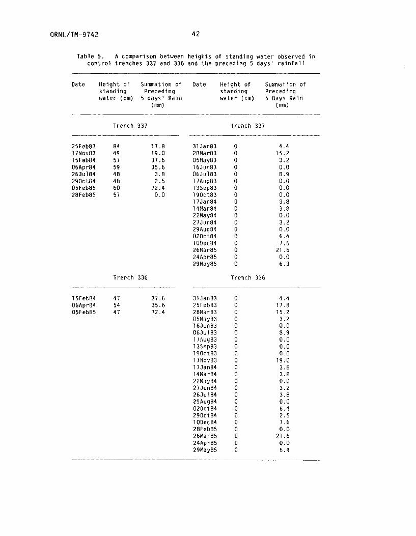
I n r e v i e w i n g t h e s i t e p r e c i p i t a t i o n reco rds , it was noted t h a t t h e
r a t h e r b r i e f p e r i o d s when wa te r was observed t o c o l l e c t i n c o n t r o l
t renches were g e n e r a l l y preceded by 5-day p e r i o d s when r a i n f a l l was
h i g h , t o t a l i n g up t o 72.4 mm { T a b l e 5 ) . I n c o n t r a s t , on dates when t h e
w e l l s i n t h e c o n t r o l t renches were observed t o be dry , t h e t o t a l
r a i n f a l l f o r t h e p reced ing 5 days was c o n s i d e r a b l y l e s s , r a n g i n g f rom 3
t o 22 mm. T h i s c o r r e l a t i o n w i t h r a i n f a l l suggests t h a t wa te r i s
e n t e r i n g these two t renches as s u r f a c e i n f i l t r a t i o n and remain ing f o r
seve ra l days u n t i l d ra inage t o t h e u n d e r l y i n g groundwater can occur.
No seasonal v a r i a t i o n i s e v i d e n t f rom F i g s . 7 t h rough 9, b u t r a t h e r t h e
wa te r i n t h e c o n t r o l t renches i s t r a n s i e n t , be ing d i r e c t l y r e l a t e d t o
i n d i v i d u a l p r e c i p i t a t i o n events . T h i s s i t u a t i o n w i l l l i k e l y c o n t i n u e
t o expose t h e con ta ined waste t o w e t t i n g and d r y i n g cyc les , which i s
t h e case f o r a number o f waste d i s p o s a l t renches a t ORNL (Spa ld ing
1984, Arora e t a1 1981, Davis and S t a n s f i e l d 1984).
F o r purposes o f m o n i t o r i n g w a t e r l e v e l s and conduc t ing h y d r a u l i c
c o n d u c t i v i t y t e s t s in t h e t h r e e g rou ted t renches, two sha l l ow w e l l s
were bored i n each t r e n c h w i t h an auger and cased w i t h 7.6-cm PYC
s l o t t e d p ipe . The auger h o l e s had t o be cased immediate ly and would
n o t remain open f o r long, due t o t h e expansion of t h e compacted waste
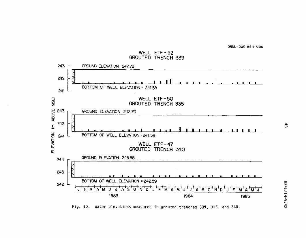
ba les a f t e r removal o f t h e auger. F i g u r e 10 summarizes t h e r e s u l t s of
t h e 29-month wa te r l e v e l m o n i t o r i n g program f o r t h r e e o f t h e s i x
ORNL/TM-9742 42
Table 5. A compar ison between h e i g h t s o f s t a n d i n g w a t e r observed i n c o n t r o l t r e n c h e s 337 and 336 and the p r e c e d i n g 5 d a y s ' r a i n f a l l
Date H e i g h t o f S u m a t i o n o f Date H e i g h t o f Summation o f s t a n d i ng P r e c e d i n g s t a n d i n g Preced ing w a t e r (cm) 5 d a y s ' R a i n w a t e r (cm) 5 Days R a i n
(m) (m) - ......... .......... .......... .
Trench 337 Trench 337 .- ___ ....................
25Feb83
15Feb84 06Apr84 26Ju 184 290ct84 05Feb85 28Feb85
17NQV83 84 49 57 59 48 48 60 57
1 7 . 8 19.0 37.6 35.6 3.8 2.5
72.4 0.0
31 Jan83 28Mar83 05May83 16Jun83 06Ju183 17Aug83 13Sep83 1 9 0 c t 8 3 17Jan84 14Ma 1-84 22May84 2 7 J u n84 29Aug84 020c t84 1 ODec84 26Mar85 24Apr85 29May85
0 0 0 0 0 0 0 0 0 0 0 0 0 0 0 0 0 0
4 . 4 15.2
3.2 0.0 8.9 0.0 0.0 0.0 3.8 3.8 0.0 3.2 0.0 6.4 7.6
21.6 0.0 6 . 3
Trench 336 Trench 336 ... -~ - ___
15Feb84 47 37.6 31 Jan83 06Apr84 54 35.6 25Feb83 05Feb85 47 72.4 28Mar83
05May83 l6Jun83 06Ju183 17Auy83 13Sep83 190c t83 1 lNov83 1 7 Jan84 1 4#a r 8 4 22Mdy84 27 Jun84 26Ju 184 29Aug84 020c t84 290c t 8 4 1 ODec84 28Feb85 26Har85 24Ap r8 5 29May85
.............. ................... .........
0 0 0 0 0 0 0 0 0 0 0 0 0 0 0 0 0 0 0 0 0 0 0
4 . 4 1 7 . 8 15 .2
3 .2 0.0 3.9 0 .0 0 .0 0.0
19.0 3.8 3.8 0.0 3.2 3.8 0.0 6.4 2.5 7 .6 0.0
21 .6 0.0 6.4
ORNL- DWG 84-1133tA
m a E v -
WELL ETF- 52 GROUTED TRENCH 339
GROUND ELEVATION 242.72 243 r I I
BOTTOM OF WELL ELEVATION = 241.58 241
WELL ETF-50 GROUTED TRENCH 335
5 w -J w
WELL ETF- 47 GROUTED TRENCH 340
GROUND ELEVATION 243.88
244 r 14 L 242 ~ 1 1 1 1 1 1 1 1 1 1 1 , 1 1 1 ~ ~ , 1 1 ~ ~ , ~ ' 1 1 ,
BOTTOM OF WELL ELEVATION =242.59
' J I F ' M ' A ' M ' J ' J ' A ' S ' O ' N ' D I J ' F ' M ' A ' M ' J ' J ' A ' S ' O ' N ' D ' J ' F ' M ' A ' M ' J 1983 1984 1985
F ig . 19. Water e l e v a t i o n s measured i n g rou ted t renches 339, 335, and 340.
P w
ORN L/ TM-9 74 2 44
grouted- t rench w e l l s . 'Ihe remain ing t h r e e g rou ted - t rench wells were
m o d i f i e d f o r use i n t r a c e r movement t e s t s and were t h e r e f o r e n o t a p a r t
o f t h e wa te r l e v e l m o n i t o r i n g n e t ~ r k .
It appears f rom F i g . 10 t h a t d u r i n g a m a j o r i t y o f t h e t i m e t h e r e
i s o n l y a min imal amount o f wa te r (5-10 cm) t rapped i n t h e bot tom o f
each w e l l ; however, l e v e l s d i d i n c r e a s e s l i g h t l y i n w e l l ETF-52 d u r i n g
t h e beg inn ing o f 1984 (February, March, and April) . The observed wa te r
cou ld have r e s u l t e d f rom leaks i n t h e g r o u t b a c k f i l l o r , more l i k e l y ,
f rom d i r e c t r a i n f a l l i n t o t h e w e l l cas ing d u r i n g p e r i o d s when the w e l l
cove r was removed, f rom leakage around t h e p o i n t a t which t h e PVC w e l l
case e n t e r s the grouted t rench , o r froin mo-isture assoc ia ted w i t h t h e
waste ba les p r i o r t o t r e n c h t rea tmen t . There i s c e r t a i n l y no evidence
t h a t wa te r l e v e l s a r e f l u c t u a t i n g w i t h i n these t renches, which i s t h e
case w i t h t h e Hypalon l i n e d trenches, and t h e r e were no ins tances o f
h i g h wa te r l e v e l measurements t h a t cou ld be c o r r e l a t e d w i t h p e r i o d s o f
heavy r a i n f a l l . Based on t hese i n t r a t r e n c h wa te r l e v e l data, g r o u t i n g
rep resen ts an improvement ove r t h e c o n t r o l t renches, because i t doer;
n o t appear t o a l l o w t h e waste t o be sub jec ted t o f l u c t u a t i n g
i n t r a t r e n c h wa te r l e v e l s r e s u l t i n g f rom r a i n f a l l i n f i l t r a t i o n .
I n summary, i n t r a t r e n c h wa te r has been de tec ted i n a l l n i n e
exper imenta l t renches a t t h e ETF, b u t t u d i f f e r i n g degrees, This
d e t e c t i o n o f wa te r i n i n t r a t r e n c h m o n i t o r i n g w e l l s does n o t n e c e s s a r i l y
i n d i c a t e t h a t a p a r t i c u l a r t r e a t m e n t has f a i l e d , o r t h a t i t i s a l l o w i n g
l a r g e q u a n t i t i e s o f water t o l each t h e waste and t r a n s p o r t
r a d i o n u c l i d e s . It s imp ly g i v e s an i n d i c a t i o n o f t h e presence o r
absence o f perched wa te r i n t h e t renches and how i t migh t be
45 ORNL/TM-9742
f l u c t u a t i n g over an annual cyc le .
program has a c t u a l l y served another impor tant func t ion :
i n fo rma t ion t h a t could be used i n p lanning a d d i t i o n a l t reatment
eva lua t i on experiments.
water l e v e l s i n two of t h e th ree l i n e d trenches l e d t o shor t - term water
pump-out t e s t s (Sect. 5.2) t h a t were n o t considered dur ing t h e
exper imental design stages. I n add i t i on , t h e response of water l e v e l s
i n t h e c o n t r o l trenches t o p r e c i p i t a t i o n events has suggested the value
o f record ing water l e v e l s i n these trenches a t s h o r t e r t ime i n t e r v a l s
du r ing a r a i n f a l l event t o g e t a more accurate est imate o f how long t h e
water remains i n t h e t rench. Thus t h i s i n t r a t r e n c h water l e v e l survey
has served severa l purposes, b u t i t must be considered w i t h a v a r i e t y
o f o the r t e s t s (Table 3) i n eva lua t ing the two t rench treatments.
This 29-month water l e v e l mon i to r ing
ga ther ing
As an example, t h e presence o f f l u c t u a t i n g
5.2 WATER PUMP-OUT TESTS FOR THE LINED TRENCHES
Dur ing t h e water l e v e l mon i to r ing surveys descr ibed i n Sect. 5.1,
i t was observed t h a t l i n e d trenches 334, 338, and 342 each contained
s tanding water t h a t appears t o f l u c t u a t e seasonal ly (F igs . 4 through 6 ) .
To de tern ine whether t h i s water i s t rapped i n the t renches o r , as t h e
seasonal f l u c t u a t i o n s might suggest, t r a n s i e n t i n nature, a water
pump-out t e s t was conducted on each o f t h e th ree l i n e d trenches. The
t e s t s were conducted w i t h t h e assumption t h a t , i f t h e water was trapped
and could n o t e x i t through t h e l i n e r , one should be ab le t o pump t h e
trenches d r y over a pe r iod o f severa l weeks and they should t h e r e a f t e r
remain dry. On t h e o the r hand, i f t h e trenches were dra ined and then
began t o c o l l e c t i n f i l t r a t i n g water a f t e r pumping stopped, the re would
be s t rong evidence t h a t t h e l i n e r system i s leak ing. To determine

ORNL/'T64-97 42 46
which o f these two cases a p p l i e d , d r a n i n g o f t h e l i n e d t renches was
i n i t i a t e d i n January 1984, a seasonal y wet i w n t h .
The %rench dra inage process was conducted u s i n g low pumping r a t e s
so a s not t o exceed t h e d e l i v e r y c a p a c i t y o f t h e i n t r a t r e n c h wells, and
t o allow ample t i m e f o r t h e wa te r dfaWdQbdn t o reach t h e outermast
l i m i t s o f t h e t r e n c h . A f t e r exper imen ta t i on w i t h seve ra l combinat ions
o f pumps and f l o w r a t e s , t h e most success fu l t r e n c h d r a i n i n g technique
was t o s iphon water (by g r a v i t y ) f r o m the t renches u s i n g 0.5-cm-ID
tygon t u b i n g t o a 208-L co l lect ion/measurement drum u n t i l , a f t e r
seve ra l days, t h e s iphon would break. The remain ing water i n t h e
t r e n c h was removed u s i n g a v a r i a b l e speed M a s t e r f l e x pump w i t h f l o w
r a t e a d j u s t e d between 15 and 400 m l / m i n acco rd ing t o t h e d e l i v e r y
c a p a b i l i t i e s o f t h e i n d i v i d u a l w e l l s . Each o f t h e t h r e e l i n e d t renches
was d r a i n e d acco rd ing t o t h i s procedure and, depending on t h e degree o f
wa te r recove ry t h a t was observed a f t e r t h e i n i t i a l pumping pe r iod , was
pumped d u r i n g seve ra l a d d i t i o n a l t i m e i n t e r v a l s spaced a u t ove r seve ra l
weeks. I n t h i s manner each t r e n c h was d r a i n e d o f as much i n t r a t r e n c h
wa te r as p o s s i b l e .
F igu res 11 th rough 13 summarize t h e r e s u l t s o f t h e water pump-out
t e s t s by showing t h e cumu la t i ve volume o f wa te r removed f rom each
t rench , t h e response, o f t h e i n t r a t r e n c h wa te r l e v e l t o pumping, and t h e
d a i l y r a i n f a l l t o t a l s f o r t h e d u r a t i o n o f t h e t e s t . Trench 342 was
i n t e r m i t t e n t l y pumped ove r a p e r i o d o f 46 days, and on February 24 a
t o t a l o f 2790 L o f water had been d r a i n e d and pumping ceased.
Likewise, t r e n c h 338 was i n t e r m i t t e n t l y pumped ove r 38 days, and an
February 23 a t o t a l o f 3220 L o f wa te r had been d r a i n e d and pumping
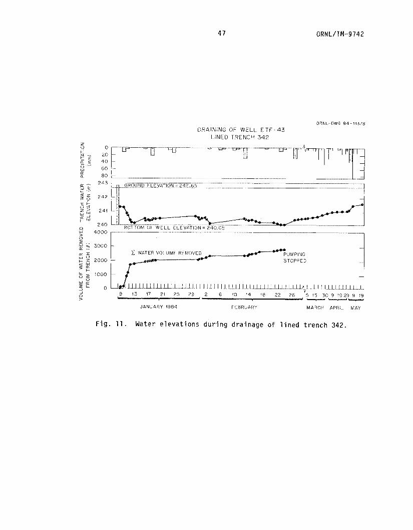
47 QRNL/TM-9742
OR N!:- I)WG 8 4 - I 1378 DRAINING OF WELL E T F - 4 3
[LINED T R E N C H 342 ........ 97 ........................ z
............................
0
k t S L d -. 0 w L1I a __
~
...
STOPPED
a
1 WATER VOLUME REMOVED AUMPING a'---
u 4000
2 2 3000
0
> J A N U A R Y 1984 FEBRUARY MARCH APRIL MA'I
F i g . 1 1 . Water e l e v a t i o n s dur ing dra inage o f l i n e d t r e n c h 342.
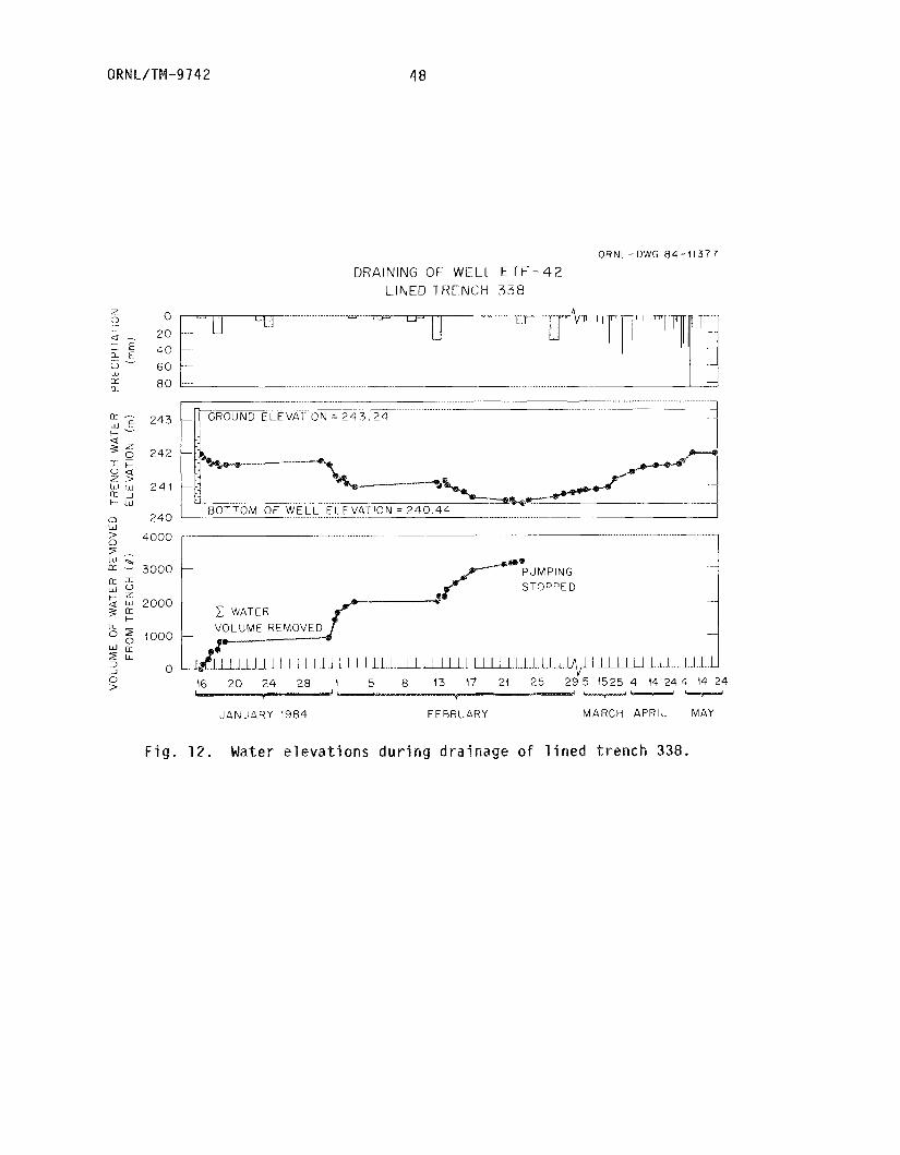
0 R N I- / TM -9 7 4 2 48
ORNL- DWG 84-11377
DRAINING OF- WELL E T F - ~ ~ LINED TRENCH 3 3 8
........................ 7
....
60 .... .......................... ................. 80
9 a -
- 0 W KK 0-
24 3
242
2 4 1
2 4 0
.................... .~~ __
.................... . . w
=;_ r.
n w 0
PUMPING Lsl 0 STOPPED I;; z 2000
0 5 1000
1 WATER U OLUME R E M
Z U
0 > .lIl.l..Il_LuILuLI~l~.~l~ ..J 0
16 20 24 28 1 5 8 13 17 21 25 2 9 5 1525 4 14 2 4 4 14 24 I v- c-spssad
JANUARY 198.1 F E BRU n R Y MARCH APRII. MAY
F i g . 12. Mater elevations d u r i n g d r a i n a g e o f l i n e d t r e n c h 338.

ClRNL/TW-9742 49
ORNL- DWG 8 4 - (1376
DRAINING OF ELL E T F - 4 1 LINED TRENCH 334
W
2 -
L L I O 0 -
> 22 24 26 2 8 5 15 25 4 14 24 4 14 24 ---w
F E B R U A R Y MARCH A P R I L MAY 1954
F i g . 13. Water elevations dur ing dra inage o f lined t r e n c h 334.

ORNL/TM-9742 50
ceased. D r a i n i n g o f t h e t h i r d t r e n c h ( t r e n c h 334) was somewhat
d i f f e r e n t because o f t h e sma l l amount o f i n t r a t r e n c h water,; a dep th o f
0.28 m as compared w i t k t 1.29 and 1.49 m c o n t a i n e d i n t renches 342 and
338, r e s p e c t i v e l y , Pumping o f t h i s t r e n c h was stopped a f t e r o n l y t h r e e
days w i t h a t o t a l o f 224 L o f w a t e r removed, l e s s by a f a c t o r o f 10
t h a n t h e volume removed f r o m t r e n c h e s 342 and 335.
A f t e r pumping ceased, t h e w a t e r l e v e l r e c o v e r y i n each o f t h e
t h r e e l i n e d t renches was observed f o r a p e r i o d o f a p p r o x i m a t e l y t h r e e
months ( F i g s . 11 t h r o u g h 13 ) . R e s u l t s i n d i c a t e tha t . w a t e r l e v e l s i n
two of t h e t h r e e l i n e d t renches ( t r e n c h e s 342 and 338) s t e a d i l y
i nc reased a f t e r pumping stopped and a c t u a l l y exceeded t h e i n i t i a l
(prepurnping) w a t e r l e v e l s . The t h i r d t r e n c h ( t r e n c h 334) m a i n t a i n e d a
r a t h e r s teady w a t e r l e v e l a f t e r b e i n g purnped u n t i l t he f i r s t week i n
Mayp when i t i n c r e a s e d to a l e v e l a p p r o x i m a t e l y 0 - 1 5 m above t h e t r e n c h
bo t tom. T h i s observed i n c r e a s e i n i n t . r a t r e n c h w a t e r l e v e l s can be
d i r e c t l y r e l a t e d t o t h e s i t e p r e c i p i t a t i o n , wh ich i s o b v i o u s l y
r e s p o n s i b l e f o r t h e l a r g e i n c r e a s e i n water l e v e l r ioted d u r i n g t h e
f i r s t week i n Nay.
I n summary, t h e r e s u l t s o f t h e s e l i n e d t r e n c h pump-out t e s t s
suggest t h a t t h e i n t r a t r e n c h w a t e r observed was n o t m e r e l y t r a p p e d as a
r e s u l t o f i n f i l t r a t i o n p r i o r t o c o v e r emplacement, b u t r a t h e r i s
t r a n s i e n t and i n f i l t r a t e s t h r o u g h h o l e s i n t h e l i n e r d u r i n g p e r i o d s o f
p r e c i p i t a t i o n . The t e s t s a r e n o t e x t e n s i v e enough t o f o r m any s o l i d
c o n c l u s i o n s about t h e e x t e n t o r s p a t i a l d i s t r i b u t i o n o f h o l e s i n t h e
l i n e r , b u t m e r e l y suggest t h a t t h e l i n e d t renches a r e n o t as w a t e r t i g h t
as i n i t i a l l y assumed. A more thorough t r e a t m e n t o f t h e i n t e g r i t y o f
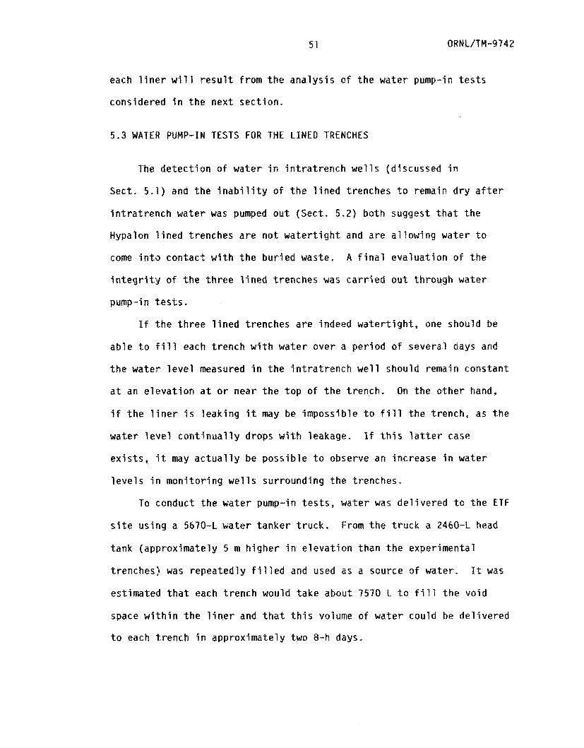
51 QRN L/TP1-974 2
each l i n e r w i l l r e s u l t f rom t h e ana lys i s o f t h e water pump-in t e s t s
considered i n t h e nex t sect ion.
5.3 WATER PUMP-IN TESTS FOR THE L I N E D TRENCHES
The de tec t i on o f water i n i n t r a t r e n c h w e l l s (d iscussed i n
Sect. 5.1) and t h e i n a b i l i t y o f t h e l i n e d trenches t o remain d ry a f t e r
i n t r a t r e n c h water was pumped ou t (Sect. 5.2) both suggest t h a t t he
Hypalon l i n e d trenches a r e n o t w a t e r t i g h t and a re a l l ow ing water t o
come i n t o contac t w i t h t h e bu r ied waste. A f i n a l eva lua t ion o f t he
i n t e g r i t y o f t h e th ree l i n e d trenches was c a r r i e d ou t through water
pump-in t e s t s .
If t h e th ree l i n e d trenches a re indeed wa te r t i gh t , one should be
ab le t o f i l l each t rench w i t h water over a pe r iod of severa l days and
t h e water l e v e l measured i n t h e i n t r a t r e n c h w e l l should remain constant
a t an e l e v a t i o n a t o r near t h e t o p o f t h e t rench.
i f t h e l i n e r 5s leak ing i t may be impossib le t o f i l l t h e t rench, as t he
water eve1 c o n t i n u a l l y drops w i th leakage. If t h i s l a t t e r case
e x i s t s
l e v e l s i n mon i to r ing w e l l s surrounding t h e trenches.
On t h e o the r hand,
i t may a c t u a l l y be poss ib le t o observe an increase i n water
To conduct t he water pump-in t e s t s , water was de l i ve red t o t h e ETF
From t h e t r u c k a 2460-L head s i t e us ing a 5670-L water tanker t ruck .
tank (approximately 5 m h igher i n e leva t i on than t h e experimental
t renches) was repeatedly f i l l e d and used as a source o f water. It was
est imated t h a t each t rench would take about 7570 L t o f i l l t h e vo id
space w i t h i n t h e l i n e r and t h a t t h i s volume o f water could be de l i ve red
t o each t rench i n approximately two 8-h days.

ORNL/TM--9142 52
On June 11, 1984, f i l l i n g o f t r e n c h 342 began w i t h t h e d e l i v e r y of
wate r a t 28 b/min f rom t h e head t ank us ing a 5-cm-dim wa te r hose, On
June 12 (one day l a t e r ) a t o t a l o f 6624 L o f wa te r had been d e l i v e r e d
t o t r e n c h 342 and f i l l i n g of t r e n c h 338 began. A t o t a l o f 7191 b o f
as added t o t r e n c h 338 on June 12 and 13. On June 14 and 15,
11,809 L was added t o t r e n c h 334. Table 6 summarizes t h e water
d e l i v e r y schedule used f o r each o f t h e t h r e e t renches .
e d i a t e l y a f t e r wa te r d e l i v e r y t o each t r e n c h was completed, a
reco rd o f t h e wa te r l e v e l w i t h i n t h e i n t r a t r e n c h w e l l was t aken as a
f u n c t i o n of t ime . F i g u r e 14 su ar imes t h e wa te r l e v e l recove ry
observed f o r each o f t h e l i n e d t renches and shows t h a t w i t h i n one day
a f t e r wa te r d e l i v e r y ceased, t h e wa te r e l e v a t i o n s i n t h e i n t r a t r e n c h
m o n i t o r i n g w e l l s had r e t u r n e d t o near t h e p r e t e s t wa te r e l e v a t i o n s .
t h e case ~f t r e n c h 342, t h e wa te r e l e v a t i o n s t a b i l i z e d a t 241.5 m,
1.47’ m above t h e t r e n c h bottom; wa te r i n t r e n c h 338 s t a b i l i z e d a t
242 m, 1 .57 m above t h e t r e n c h bottom; and wa te r i n t r e n c h 334
s t a b i l i z e d a t 240.5 m, 0.74 m above the t r e n c h bottom. These r a p i d l y
decreas ing wa te r e l e v a t i o n s suggest t h a t t h e l i n e r s a r e indeed l e a k i n g
wa te r and may have a t e a r o r punc tu re a t those r e s p e e t j v e e l e v a t i o n s .
I n
I n a d d i t i o n t o m o n i t o r i n g t h e wa te r l e v e l s i n t h e i n t r a t r e n c h
w e l l s d u r i n g t h e wa te r purnp-in t e s t s , wa te r l e v e l s were recorded i n 12
wells ( f o u r around each l i n e d t r e n c h ) t h a t a r e l o c a t e d around t h e
exper imenta l t renches { F i g . 1 ) . I f wate r i s c o n f i n e d t o t h e l i n e d
t rench , t hese surrounding w e l l s should m a i n t a i n a cons tan t wa te r l e v e l
throughout t h e pump-in t e s t . Tables 7 t h rough 9 show t h e changes i n
wa te r e l e v a t i o n s t h d t occurred w i t h i n these m o n i t o r i n g we115 d u r i n g
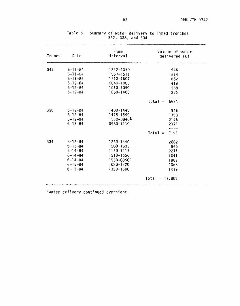
53 OR W L/ JM -9 742
Table 6, Summary o f w a t e r delivery t o lined trenches 342, 338, and 334
Trench Oate T i me
interval Volume o f water del i vered ( L )
342 6-1 1-84 6-1 1-84 6-1 1-84 6-1 2-84
6-1 2-84 6-1 2-84
338 6-1 2-84 6-1 2-84 6-1 2-84 6-1 3-84
3 34 6-1 3-84 6-1 3-84 6-1 4-84 6-1 4-84 6-1 4-84 6-1 5-84 6-1 5-84
131 2-1 350 1357-1 51 1 1 51 3-1 607 0840-1 000 101 0-1 050 1050-1 400
1400-1 440 1445-1 550 1 550-0840a 0930-1 11 0
1330-1 440 1500-1 635 1150-1415 1510-1550 1 550-0850a 1030-1 320 1320-1 500
946 1514
852 1419
568 1325
Total = 6624 - .. --
946
21 76 21 71
Total = 7191
i 798
I- -_
2082 946
2271 1041
2063 1419
1987
-_-I^-
T o t a l = 11,809 -~ - - ~-
% d a t e r delivery continued overnight.
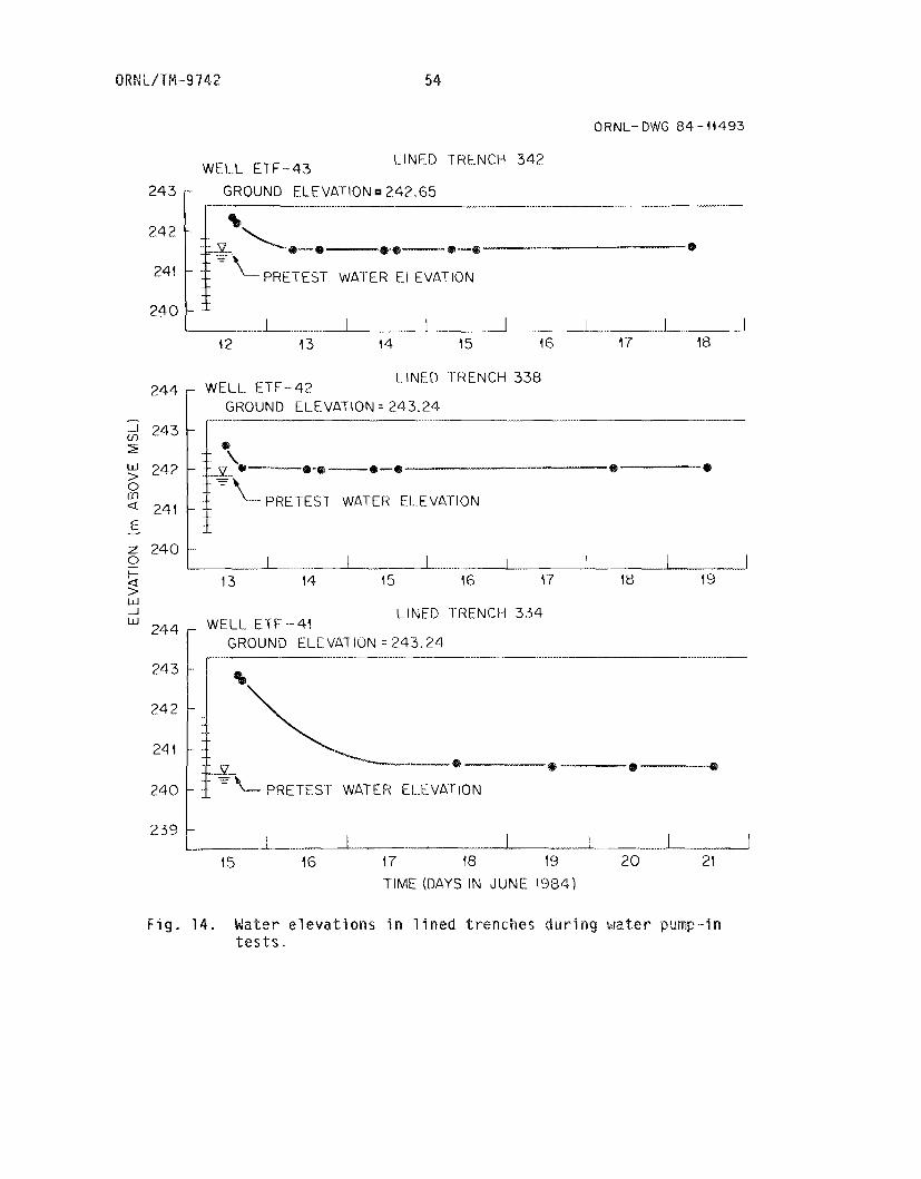
54
244
243
2 4 2
241
240
ORNL-DWG 84-11493
- ..
-
-
-
W E L L ETF-43 LINED 'TRENCH 342
24 3 LEVATION 242.65
24 2
......... .....
%$-
24 1 e_ PRETEST WATER ELEVATION
24 0 .......... I i . 1 I ..... 1 2
i 2 13 14 15 16 17 18
LINED TRENCH 338
-. GROUND ELEVATION = 243.24
......
--. _I_.
PRETEST WATER El..EVATION
z
t- 0
P ........ I__L___I ........ ..up__ u 2 4 0 1 ,
13 14 15 16 1 7 18 I9
w J W WELL ETF - 41
LINED TRENCH 334
GROUND ELEVATION = 243.24 .-. ...... _____...... I____
e------- BB
- k.- PRETEST WATER ELXVA'PION
1s 17 18 19 2 0 21 TIME (DAYS IN JUNE 1994)
F i g . 1 4 . Mater elevations i n lined trenches d u r i n g water pu t e s t s "

55 ORNL/TPl-9742
Tab le 7 . Water e l e v a t i o n s in four wells s u r r o u n d i n g t r e n c h 342 d u r i n g w a t e r pump-in t e s t s a
6-11-84 1530 1540 1550 1600 1630
6-12-84 0840 0930 1000 1040 1100 1320 1420 1510 1600
1140 1630
6-14-84 1320 6-15-84 0845
1520 6-18-84 0830
6-13-84 0840
High Low
D i f f e r e n c e
238.31 238.31 238.30 238.31 238.32 238.44 238.45 238.46 238.46 238.46 238.49 238.49 238.50 238.53
239.09 239 (. 35 238.78 238 e 66 238 e 63 238.45
238.97
239.35 238.30
1.05 ---I--
238.38 238.40 238.43 238.45
239.10 239.07 239.10 239.16
239.41 239.47 239.50 239.52 239 - 4 5 239.32 239.24 238.82
238.54
239.18
238.68 238.65 238.45
239.52 238.38
1.14
239.12 239.18 239.32 239.44 239.75 239.44 239.60 239.97 240 e 25 240.32 240.72 240.79 240.79 240.77 239.86 239.53 237.27 238.63 238.48 238.46 238.24
240.79 238.24
2.55
238.16 238.17 238 20 238 21 238.27 238.55 238.55 238.57 238.61 238.64 238.80 238.85
238 e 89 238.99 238.72
238 + 44 238.37 238.36 238.20
238. 87
238 a 65
abJater d e l i v e r y s t a r t e d a t 131 2 on 6-1 1-84.
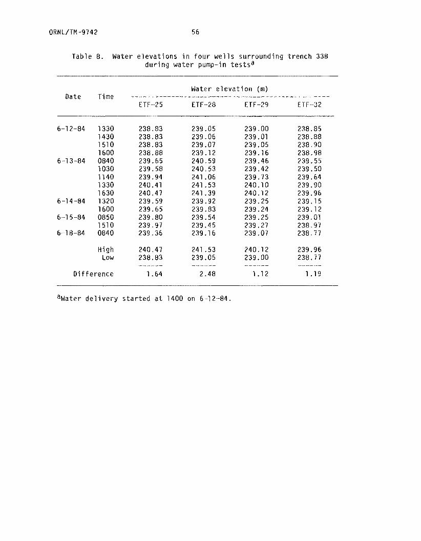
OANL/TM-9742 56
Table 8. Water e l e v a t i o n s i n four w e l l s su r round ing t r e n c h 338 d u r i n g water pump-in t e s t s a
W a t e r e l e v a t i o n ( m )
ETF-25 ETF-28 ETF-29 E T F -3 2 Date Time
6-12-84 1330 1430 1510 1600
5-13-84 0840 1030 1140 1330 1630
1500
1510
6-14-84 1320
6---15-84 0850
6-1 8-84 0840
High Low
D i f f e r e n c e
238.83 238.83 238 83 238.88 239.65 239.58 239.94 240.41 240 e 47 239 59 239.65 239 80 239 9 1 239-36
240 e 47 238.83
239.05 239 I 86 239.07 239.12 240.59 248,53 241.06 241.53 241.39 239.92 239.83 239.54 239.45 239.16
241.53 239 .05
239.80 239.01 239.05 239.16 239.46 239.42 239.73 240,10 240.12 239.25 239.24 239.25 239.27 239.07
240.12 239.00
238.85 238.88 238.90 238 I 98 239.55 239.50 239-64 239.90 239.95 239.75 239.12 239 01 238-97 238 77
239.96 239,77
1.19
%later del i v e r y s t a r t e d a t 1400 on 5-1 2-84.
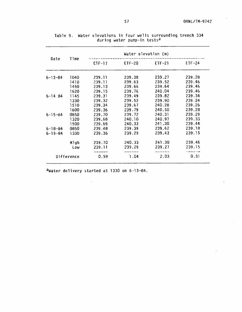
5 1 ORNL/TN-9742
Table 9. Water e l e v a t i o n s i n f o u r wells su r round ing t r e n c h 334 d u r i n g wa te r pump-in t e s t s a
6-13-84 1040 1410 1450 1620
1330 1510 1600
1320 1500
6-14 a4 1145
6-15-84 0850
6-18-84 0850 6-19-84 1330
H i g h LQW
D i f f e r e n c e
239.11 239.11 239.13 239.15 239.31 239.32 239.34 239.36 239.70
239.69 239.48 239.36
239.68
239.70 239.11
0.59 ------
239.38 239.63 239.66 239.76 239.49 239.52 239.67 239.79 239.72 240.10 240.33 239.39 239.29
240.33 239.29
1.04 --I---
239 e 27 239.52 239.64 240.04 239.82 239.90 240.28 240.50 240.31 240.97 241.30 239.62 239.43
241.30 239.27
2.03
239.28 239.46 239.46 239.46 239.34 239.24 239.26 239.28 239.29 239.33 239.44 239.18 239.15
239.46 239.15
0.31 --
ahfater d e l i v e r y s t a r t e d a t 1330 on 6-1 3-84.
ORNL/TM-9742 58
wa te r d e l i v e r y t o each t rench ; these changes suppor t t h e conc lus ion
t h a t t h e t h r e e l i n e r s a r e l e a k i n g . W i t h i n seve ra l hours o f ccs
t h e pump-in t e s t , w a t e r i n these m o n i t o r i n g w e l l s began t o r i s e t o an
e l e v a t i o n between 0.31 and 2.55 higher t h a n t h e p r e t e s t l e v e l s . I n
genera l , t h e p a i r o f w e l l s t o t h e west and e a s t of the t r e n c h be ing
f i l l e d ( w e l l s ETF -36, -37, -28, -29, -20, and -21) showed t h e g r e a t e s t
response t o t h e pump-in t e s t s , which p robab ly r e s u l t s f rom t h e s i m i l a r
o r i e n t a t i o n o f t h e g e o l o g i c s t r i k e (NSQE) (Vaughan e t a l . 1982).
I n summary, a l l t e s t s designed t o e v a l u a t e t h e performance o f t h e
t h r e e l i n e d t renches i n d i c a t e t h a t t h e y a r e n o t w a t e r t i g h t . Though t h e
i n t r a t r e n c h w e l l s w i l l accept wa te r a t a r a t e o f app rox ima te l y 28
L/min, t h e wa te r i s n o t con ta ined w i t h i n t h e l i n e r b u t i s e x i t i n g f r o m
t h e t r e n c h and causing wa te r e l e v a t i o n s i n surrounding wells t o
i n c r e a s e th rough t h e d u r a t i o n o f t h e t e s t .
e n t e r i n g and l e a v i n g t h e t renches may be decreased somewhat by t h e
presence o f t h e impermeable l i n e r ; however, t h e t h r e e r e p l i c a t e l i n e d
t renches can n o t be considered a b s o l u t e l y w a t e r t i g h t , as was t h e des ign
goa l . For t hese reasons t h e Hypalon f a b r i c l i n e r as c o n s t r u c t e d i n
t h i s demonstrat ion cannot be reco ended as an improvement t o p r e s e n t
sha l l ow land b u r i a l p r a c t i c e s .
The t o t a l f l u x of wate r
5 . 4 HYDRAULIC CONDUCTIVITY OF THE WASTE-BACKFILL
The f o u r t h t r e n c h t r e a t m e n t e v a l u a t i o n p e r t a i n s t o t h e grouted and
c o n t r o l t renches and i n v o l v e s measurement and comparison of t h e
w a s t e - b a c k f i l l h y d r a u l i c c o n d u c t i v i t y . I n t h i s case t h e t e r m h y d r a u l i c
c o n d u c t i v i t y a c t u a l l y means t h e a b i l i t y o f i n t r a t r e n c h w e l l s i n these
t&ro c lasses o f t renches t o accept wa te r under s a t u r a t e d c o n d i t i o n s . I f

59 ORNL/TM-9742
water f r e e l y f lows i n t o t h e i n t r a t r e n c h we l l s , and a r e l a t i v e l y h igh
hyd rau l i c c o n d u c t i v i t y r e s u l t s , one can assume t h a t t he re i s a l a r g e
amount o f v o i d space i n t h e t rench and t h a t t h e l i m i t i n g f a c t o r f o r
water acceptance i n the w e l l s i s l i k e l y t o be the s ide w a l l s and bottom
o f t he t renches, n o t t h e was te -back f i l l m ix tu re . Under these
cond i t i ons o f l a r g e i n t r a t r e n c h vo id space and h igh was te -back f i l l
hyd rau l i c c o n d u c t i v i t y , one can assume l i t t l e p r o t e c t i o n o f t he waste
f rom i n f i l t r a t i n g water, e i t h e r r a i n f a l l i n f i l t r a t i o n o r shal low
subsurface f l ow .
I n t h e case o f t h e cement-bentonite t r e a t e d trenches, t he voids
between waste bales were f i l l e d w i t h g rou t and the i n t r a t r e n c h w e l l s
should n o t accept water as f r e e l y as t h e c o n t r o l t renches, y i e l d i n g a
lower va lue f o r was te -back f i l l hyd rau l i c c o n d u c t i v i t y . Under these
cond i t i ons o f minimal vo id space and low h y d r a u l i c conduc t i v i t y , t h e
waste can be considered b e t t e r i s o l a t e d and t h e degree o f i s o l a t i o n can
be q u a n t i t a t i v e l y compared w i t h r e s u l t s f rom t h e c o n t r o l (un t rea ted)
t renches.
The method f o r t he de terminat ion o f sa tura ted hyd rau l i c
c o n d u c t i v i t y (K) i n t h e th ree c o n t r o l and th ree grouted trenches was
t h a t o f a w e l l p o i n t f i l t e r loca ted i n un i fo rm s o i l (Hvorslev 1951).
Us’nng t h i s method, one can measure e i t h e r t h e f l o w r a t e (9) requ i red t o
ma’nntain water a t a constant head w i t h i n t h e w e l l o r t h e t ime requ i red
f o r t he head t o f a l l f rom p o i n t H, t o p o i n t H2.
t h e sa tura ted hyd rau l i c c o n d u c t i v i t y can be ca l cu la ted from the
f o l l o w i n g equat ions developed by Hvorslev.
I n e i t h e r case,
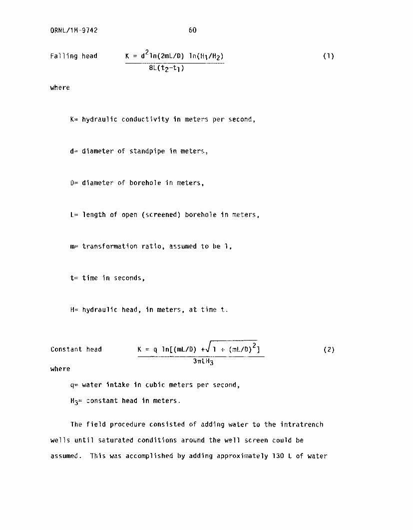
Falling head 8L( t z - t l )
where
K= hydraulic conductivity i n meters per secon
d= diameter of standpipe i n meters ,
a- diameter o f borehole i n
L= length o f open (screened) borehole i n mete?-s,
rn= t ransformat ion r a t l o , assumed t o be 1,
t= time i n seconds,
H=: hydraulic head, i n meters, a t t i m e -te
Constant head K = q ln[(rnL/D] + 7 1 -6- (rnL/D) 3
q= water intake i n cubic meters per second,
Hg= constant head i n meters,
The f i e l d procedure consisted o f adding wate r t o the intratrench
wells u n t i l saturated conditions around the well screen could be
assumed. This was accomplished by adding approximately 130 L o f water
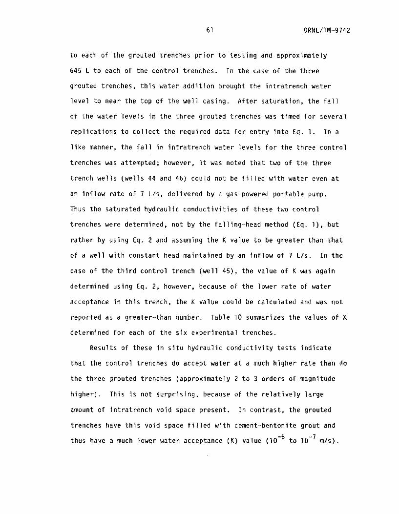
61 ORNL/TW-9742
t o each o f t h e g rou ted t renches p r i o r t o t e s t i n g and approx ima te l y
645 l. t o each o f t h e c o n t r o l t renches . I n t h e case o f t h e t h r e e
g rou ted t renches, t h i s w a t e r a d d i t i o n b rough t t h e i n t r a t r e n c h wa te r
l e v e l t o near t h e t o p o f t h e w e l l cas ing , A f t e r s a t u r a t i o n , t h e f a l l
o f t h e w a t e r l e v e l s i n t h e t h r e e g rou ted t renches was t imed f o r seve ra l
r e p l i c a t i o n s t o c o l l e c t t h e r e q u i r e d da ta f o r e n t r y i n t o Eq. 1.
l i k e manner, t h e f a l l i n i n t r a t r e n c h wa te r l e v e l s f o r t h e t h r e e c o n t r o l
t renches was at tempted; however, i t was noted t h a t two o f t h e t h r e e
t r e n c h w e l l s ( w e l l s 44 and 45) c o u l d n o t be f i l l e d w i t h wa te r even a t
an i n f l o w r a t e o f 7 L/s , d e l i v e r e d by a gas-powered p o r t a b l e pump.
Thus t h e s a t u r a t e d h y d r a u l i c c o n d u c t i v i t i e s o f these two c o n t r o l
t renches were determined, n o t by t h e f a l l i n g - h e a d method (Eq. l ) , b u t
r a t h e r b y u s i n g Eq. 2 and assuming t h e K va lue t o be g r e a t e r t han t h a t
o f a w e l l w i t h c o n s t a n t head ma in ta ined by an i n f l o w o f 7 L i s . I n t h e
case o f t h e t h i r d c o n t r o l t r e n c h ( w e l l 45), t h e va lue o f K was a g a i n
determined u s i n g Eq. 2, however, because of t h e l ower r a t e o f wa te r
acceptance i n t h i s t rench , t h e K va lue c o u l d be c a l c u l a t e d and was n o t
r e p o r t e d as a g rea te r - than number. Table 10 summarizes t h e va lues o f K
determined f o r each o f t h e s i x exper imenta l t renches .
In a
R e s u l t s o f t hese i n s i t u h y d r a u l i c c o n d u c t i v i t y t e s t s i n d i c a t e
t h a t t h e c o n t r o l t renches do accept wa te r a t a much h i g h e r r a t e than do
t h e t h r e e g rou ted t renches (app rox ima te l y 2 t o 3 o rde rs o f magnitude
h i g h e r ) . Th i s i s n o t s u r p r i s i n g , because o f t h e r e l a t i v e l y l a r g e
amount o f i n t r a t r e n c h v o i d space p resen t . I n c o n t r a s t , t h e g rou ted
t renches have t h i s v o i d space f i l l e d w i t h cement-bentoni te g r o u t and
thus have a much lower wa te r acceptance ( K ) va lue t o m/s ) .
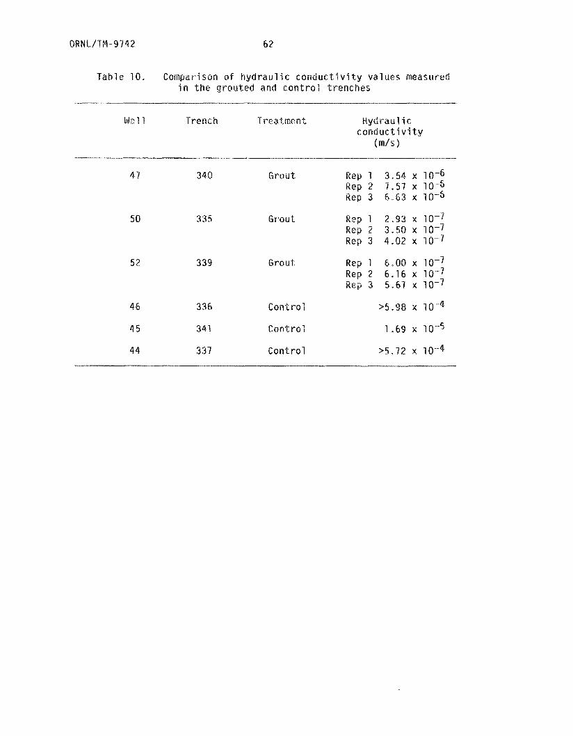
ORNL/?M-9742 62
Table 10. Comparison o f hydraul i c conductivity values measured i n t h e g r o u t e d a n d c o n t r o l t r e n c h e s
Ne1 1 Trench T r e atme hl t Kydraul i c conductivity
( m / s )
47 340 Gt-0U-t Rep 1 3,54 x 10⁻⁶ Rep 2 7 . 5 7 x 10⁻⁵ Rep 3 6 - 6 3 x l0lb
50 335 Grou t Rep 1 2.93 x 10⁻⁷ Rep 2 3.50 x 10⁻⁷ Rep 3 4.82 x 10⁻¹
52 339 Grout Rep 1 6,00 x lo-? Rep 2 6.16 x l o q 3 Rep 3 S.67 x 10-7
46 336 Control >5.98 x 10⁻⁴
45 34i C o n t r o l 1.69 x 10⁻⁵
44 337 Control > s . x x 10-4
Any wa te r t h a t seeped i n t o t h e g rou ted t renches d u r i n g these t e s t s
p robab ly t r a v e l e d th rough f i s s u r e s i n t h e waste ba les and may have
a c t u a l l y e x i t e d f rom t h e t r e n c h i f t h e f i s s u r e s extended t o t h e s i d e s
o f t h e grout /waste mass.
I n summary, f i e l d measurements o f h y d r a u l i c c o n d u c t i v i t y i n the
grou ted and c o n t r o l t renches i n d i c a t e t h a t t h e c e m e ~ t - b ~ n ~ o n i t e g rou t
reduces t h e h y d r a u l i c c o n d u c t i v i t y o f t h e w a s t e - b a c k f i l l m i x t u r e by 2
t o 3 o r d e r s o f magnitude. Values o f K measured i n t h e g rou ted t renches
ranged f rom 7 . 5 7 x t o 2.93 x m/s and a r e o f t h e same
magnitude as K values measured i n t h e u n d i s t u r b e d Conasauga Format ion
(6 .3 x m/s). Conversely, K values measured i n t h e c o n t r o l
t renches a r e much l a r g e r , r a n g i n g f r o m 1.69 x
i n d i c a t i n g l i t t l e r e s i s t a n c e t o wa te r movement. T h i s reduced hy
c o n d u c t i v i t y means a g r e a t e r r e s i s t a n c e t o w a t e r f l o w and an added
degree o f h y d r o l o g i c p r o t e c t i o n f o r waste p laced i n t h e g rou ted
t renches.
t a X5.98 x w4,
5 . 5 STRENGTH AND D U R A B I L I T Y OF HATERIALS
An I m p o r t a n t q u e s t i o n i n t h e e v a l u a t i o n o f t r e n c h g r o u t i n g and
l i n i n g , as c a r r i e d o u t i n t h i s f i e l d demanstrat ion, i s t h e s t r e n g t h and
d u r a b i l i t y o f t h e m a t e r i a l s used. In t h e case o f the grou t , the
expected r e d u c t i o n i n cove r subsidence and h y d r o l o g i c i s o l a t i o n o f t h e
waste i s o f l i t t l e va lue i f t h e p r o p e r t i e s o f t h e s e t g r o u t a r e such
t h a t i t l a c k s t h e necessary s t r e n g t h t o w i t h s t a n d t h e env i ronmenta l
c o n d i t i o n s ( temperature, p r e c i p i t a t i o n , and mechanical s t resses ) l i k e l y
t o be encountered w i t h extended s to rage a t l o w - l e v e l waste

QRN L/TM-3 7 42
s i t e s . L ikewise, a r n d t e r i a l used t o l i n e a t r e n c h must r e t a i n i t s
shear s t r e n g t h , r e s i s t a n c e t o puncture, and i m p e r m e a b i l i t y i f i t i s t o
serve i t s i n tended purpose o f waste i s o l a t i o n i n f u t u r e years. Th is
assurance o f d u r a b i l i t y f o r extended pe r iods o f t ime w i l l c e r t a i n l y be
an i m p o r t a n t f a c t o r i n p u b l i c acceptance o f any type o f m a t e r i a l used
f o r improved sha l l ow l a n d b u r i a l I
To i n v e s t i g a t e t h e q u e s t i o n o f d u r a b i l i t y o f t h e t w o m a t e r i a l s
(cement-bentoni te g r o u t and Hypa'lon f a b r i c ) be ing t e s t e d a t t h e ETF, a
g r o u t and l i n i e r ag inq s tudy was i n i t i a t e d i n February 1984. l h e
purpose o f t h e s tudy 5~a5 t o examine t h e sho r t - te rm ( 2 - 3 yea rs ) changes
i n s e l e c t e d eng ineer ing p r o p e r t i e s o f g r o u t and l i n e r specimens s i m i l a r
t o those used a t t h e ETF. I f changes i n measured p r o p e r t i e s occur w i t h
sho r t - t e rm exposure t o t h e elements, and i f these changes suggest
f u t u r e t r e a t m e n t f a i l u r e , t hen t h e r e w i l l be some b a s i s f o r making
meaningfu l p r e d i c t i o n s about t h e f u t u r e performance ( l i f e t i m e ) o f
s i m i l a r l y t r e a t e d t renches . I f , on t h e o t h e r hand, t h e r e a r e no
d e t e c t a b l e changes i n eng ineer ing p r o p e r t i e s ove r t h e s h o r t term,
l onger - te rm exper iments examining m a t e r i a l s d u r a b i l i t y would be
r e q u i r e d t o g a t h e r meaningfu l da ta a p p l i c a b l e t o 50-1630 years i n t h e
f u t u r e . Thus t h e ag ing exper iments desc r ibed here a p p l y t o t h e s h o r t
t e r m and a r e designed t o d e t e c t r a t h e r ab rup t changes i n s e l e c t e d g r o u t
and 1 i n e r p r o p e r t i e s .
An i m p o r t a n t eng inee r ing p r o p e r t y of t h e cement-bentoni te g r o u t ,
and t h e one s e l e c t e d f o r examinat ion i n t h i s exper iment, i s t h e
unconf ined compressive s t r e n g t h (ASTM C 109-80) o f t h e s e t g r o u t . I f
t h i s s t r e n g t h , measured as t h e f o r c e p e r u n i t area r e q u i r e d f o r

65 ORNL/TM-9742
breakage o f a c y l i n d r i c a l g r o u t specimen, decreases s i g n i f i c a n t l y w i t h
t ime, t h e n t h e g r o u t i s g r a d u a l l y l o s i n g i t s s t r e n g t h and will l i k e l y
f o r m c racks and f i s s u r e s th rough t i m e as t h e r e s u l t o f n a t u r a l
s t resses . A dec reas ing compressive s t r e n g t h would o b v i o u s l y n o t be a
d e s i r a b l e g r o u t p r o p e r t y . F o r t h e Hypalon l i n e r e v a l u a t i o n , shear
s t r e n g t h (ASTM D 751-79) and punc tu re r e s i s t a n c e were s e l e c t e d as t h e
two eng ineer ing p r o p e r t i e s t o examine.
t h o u g h t t o b e s t c h a r a c t e r i z e t h e r e s i s t a n c e o f t h e f a b r i c t o punc tu re
o r t e a r i n g by waste packages, t h e most l i k e l y cause o f t r e a t m e n t
f a i 1 u re .
These two p r o p e r t j e s a r e
To c a r r y o u t t h e ag ing exper iment, 100 samples o f cement-bentoni te
(7-cm-high c y l i n d e r s w i t h a r a d i u s o f 2.75 cm) and 200 s t r i p s o f
Hypalon f a b r i c (each s t r i p 2 .5 by 20.3 cm) were prepared f o r t e s t i n g .
I n t h e case o f t h e Hypalon s t r i p s , t h e samples were taken from a p i e c e
o f t h e f a b r i c t h a t was l e f t o v e r f rom t h e t r e n c h l i n i n g o p e r a t i o n s t h a t
t ook p l a c e i n t h e summer o f 1982. Thus t h e specimens can be considered
r e p r e s e n t a t i v e o f t h a t used t o l i n e t h e ETF t renches . However, t h e
cement-bentoni te g r o u t samples were n o t c o l l e c t e d f r o m t h e d e l i v e r y
t r u c k s t h a t a c t u a l l y f i l l e d t h e t h r e e t renches s e l e c t e d f o r g r o u t i n g ,
b u t i n s t e a d were made up a t a l a t e r da te acco rd ing t o i d e n t i c a l
s p e c i f i c a t i o n s (Sect. 3.2), The one i m p o r t a n t f a c t o r t h a t cou ld n o t be
reproduced i n p r e p a r i n g these g r o u t specimens was t h e shear d e l i v e r e d
by t h e cement m i x i n g t r u c k . T h i s shear f a r c e was reproduced as n e a r l y
as p o s s i b l e u s i n g a bench-top 3.78-L p o l y e t h y l e n e m i x i n g vessel
equipped w i t h s i d e vanes, i n which t h e t h r e e i n g r e d i e n t s (water ,
cement, and b e n t o n i t e ) were comp le te l y mixed d u r i n g sample p r e p a r a t i o n .
0 R N L/TM -9 7 4 2 66
Thus t h e g r o u t specimens must be eva lua ted w i t h t h e c o n d i t i o n t h a t t h e y
came f rom ;a d i f f e r e n t b a t c h o f cement-bentoni te and may o r may n o t be
i d e n t i c a l t o t h a t used i n t h e t h r e e ETF t renches .
A f t e r sample p r e p a r a t i o n , a t o t a l o f f i v e subsets (one subset
c o n s i s t i n g o f 10 randomly s e l e c t e d g r o u t c y l i n d e r s and 20 randomly
s e l e c t e d l i n e r s t r i p s ) were b u r i e d a t a depth o f 30 cm a t t h e ETF j u s t
w e s t o f t h e exper imen ta l t r e n c h e s . I n t h i s manner t h e Sam
exposed t o t h e same n a t u r a l c o n d i t i o n s as t h e m a t e r i a l i n the
exper imen ta l t renches and c o u l d be e a s i l y r e t r i e v e d f o r scheduled
a r i z e d i n t h e exper imen ta l des ign (Tab le 11) .
A s seen in Table 11, t h e exper iment examines chan e% i n t h e t h r e e
s e l e c t e d e n g i n e e r i n g p r o p e r t i e s as a f u n c t i o n o f t i m e f o r a p e r i o d o f 2
years. To da te , t h r e e s e t s o f samples, t hose co r respond ing t o t h e
subsets t o be tesaed a f t e r 4 , 10, and 15 months, have been r e t r i e v e d
and t e s t e d . I n t h e f u t u r e , r e t r i e v a l o f sample subsets 4 and 5 w i l l
c o n t i n u e as scheduled (Tab le 11) t o complete t h e exper iment i n FY 1985.
Unconf ined compressive s t r e n g t h o f t h e cement-bentoni te specimens
was performed u s i n g a Karal--Warner I n c . , madel KW 557 unconf ined
compression t e s t e r equipped w i t h a model KW 2500 R load r i n g capable o f
d e l i v e r i n g a maximum o f 1134 kg t o a s i n g l e specimen. The l o a d t o t h e
t o p o f each specimen was g r a d u a l l y i nc reased a t a p p r o x i m a t e l y 30-5
i n t e r v a l s u n t i l t h e c y l i n d e r specimen cracked o r s p l i t i n t o p ieces ,
i n d i c a t i n g t h a t t h e unconf ined compressive s t r e n g t h had been exceeded.
The l o a d (kg) causing t h e specimen t o f a i l was t h e n conver ted t o a
p ressu re o r s t r e s s ( k g m-2 m s
area o f t h e c y l i n d e r (m ) and m u l t i p l y i n g by t h e a c c e l e r a t i o n due t o
-2 ) by d i v i d i n g by t h e t o p s u r f a c e 2
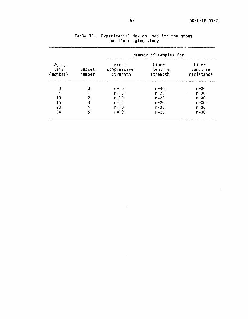
67 ORNL/TM-97 42
Table 11. Experimental design used f o r the g r o u t and l i n e r aging s t u d y
Number o f samples f o r ----------.--cI-----_______111_1___1-I.---.---I--
Aging Grout Liner t.i ner time Subse t compress i ve t e n s i l e puncture
(months ) number strength strength resis tance
0 0 n=lO n=40 n=30 4 1 n=lO n=20 n=30
10 2 n=lO n-20 n=30 1 5 3 n = l O n=20 n=30 20 4 n=lO n=20 n=30 24 5 n=lO n=20 n=30
0
9
m rB
3.
Lu
W U ?. !G
(3
3-
d.
v)
n
n
5.
v)
-h w fi 0
7
0
-h
N
n
v)
rt
3
CD
v)
rt -5 m 3
a
rt
3
d.
#
5
CD
- 2 0 I js
0
-h
0 3
0
m -5 J
3
rca
rt I
CD
0
=I an I e
ib
-5 3
m
rt
!3J
W
-1.
-1
-1. d
d.
r+
Y
0
--h
rt a
CD
ckd
-3
0
a
v)
rt
8,
3
r(.
2- 0
-5
rt
0 3 z a
P,
9
0
4
m
a,
in
m P
0
c 2. 3 rca
4.
P
7
d.
U
v)
r+ a
0
rp 3.
-5
9
ce
la
-5 0
S
ri-
c1
rt Lu
W
B
wl
-! 5
0
d
2.
I ct
CD
77
Ln
3,
d
lrl
I KJ
v
r-t e
v) a
c
m
2-
A*
a
7 0
E
rt
3
x
fi
-1
a
5 !a
#
5
CD a
5 LA
0
-h
0
C
m 1
-1
0
7
m 5 m
0
8
OD
'T
0
n
E n 2
6 n
0
c
?D
m
m
x
-a
0
m
I= a
#
0 3
P
-5 CD
ln
v) e
$9
v) * a m s rca
rt 3
LZ
a
3
0
rt
0
5
e,
9
era
CD
2.
a.
Eu
vl
(n 3
--h
d.
d.
2.
rt 3
CD
Lb
d.
0
a
C7
CD
VI e, 3
?
CD
v
r+
0 3
U1
n
A.
-?I
0
7
--I. 3
la
cl- A.
d. 7
rp
s -1. 3
0
I2
Q
7
Q f
rt
U
U
fb a
m
Y
LI
-I e,
CT
Y) c
CT
in
m
r+
CD
bl r+
PD
Q
-1
fD
cb
3
m v)
c
Y)
9
0
-1.
2.
a a
W 0
c 3 a
m
a.
VI
4.
rt
5
a.
n
P,
i-t d.
r+
N
n
'j
CD
v) m
d.
-I I
CD
7
3
3
(n
s3
3
m
a.
-I.
3
rt 3-
M
m X
W m 4
-1.
2.
VI c 0-
LA
m
s a
r 3 2
3
rca
'0
CD
7
<
CD
W 6
2.
9
ra
CD
h
d.
N
VI
io
rt
7
CD 3
(Q
rF
a
ln
CD
X
W 1
CD
m
VI
CD a
-1.
3
7-7 2.
--1
d
-1.
a
La
M
cn
d
(B
'/I
d.
3
rt
wl
0
4
A:
CD
W,
r+ 3
CD
-1.
h e
W
vi
rc
c; 3
id
wl
rt CD a
r(.
5
CD
7
Y
0
d.
s
e,
3 a
3 7 CL
CD
S
ct
m
r+
m
ffi
-h 0
7
co n
u-
EI
2.
a
5
n
3
0 3
r+ I
ir,
rt 0
i 0 3 a d.
rt a,
-1
3.
i-t
Y
CY 2
-1
3
(B
Lu 3
rt
G
in
-1.
d
c
rt
U
-5 0 U
e,
W
cl
CD
m
n
W
v)
d.
Y
0
-h
A e, VI
a
m -h
1 c-k
m
-5 0
B
m
e,
4
CD
w- m
VI + 2. -1
-I
a
-1.
d.
tn 3
-*
r+
3
m d,
7
ce
0
7
an
rt 2.
-1.
a
3-
rt 2 A.
-1
Y
0 3
m 3
ln
r+
7
Y
dr
h
-h
7
rt
--I.
0
t
'4
(B
7 0
c
t-t
>
m
.-
w 0 3 a
0
W
7
m ;n
v) <
CD
d.
N
w 0
CD
ln
ln
r+ m B
(3
=r m
a
m
n
w 0
0
=r 2.
J
0
--h
-h
Fu
cf
-3 c,
d.
W
DJ ce 1
0
c
,r?
-1
0
W
cu
rn
R
!3J m
-I
(3 Y
m lrl 0
7 .
d.
Y
-5 CD
D
, VI
d.
Yl
CD 0
7
U
w
P,
0
d .T
rD
5
H
r+
h
E
tD
co
Cl.
0 9
m
4.
rt
3
m
v, 3.
0 3
-1.
3
--I a
CD
..
0
Sa
m (3
I
d 3
d
s: !a
w
e
d
d.
V#
r+
5
m
0
-fl
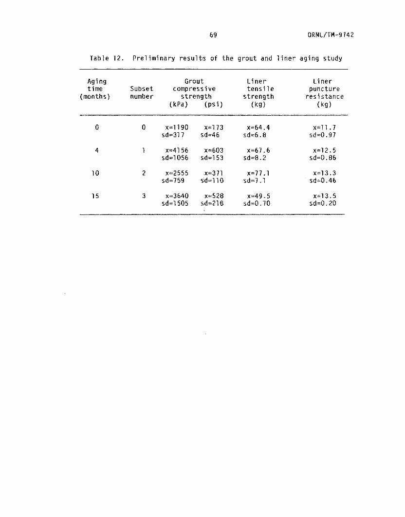
69 0 R N L / TM-9.7 4 2
Table 1 2 . Preliminary results o f the grout and l iner aging s t u d y
Aging Grout Li net- Liner time Subset compressive tens i le puncture
( months 1 number strength s t rength resistance (kPa) (ps i ) (kg) (ksf
0 0 x=ll90 sd=317
4 1 ~ ~ $ 1 5 6 sd=lO56
10 2 x=2555 sd=7 59
1 5 3 ~ = 3 6 4 0 sd=1505
x=l13 sd=46
x=371 sd=llO
~ ~ 6 4 . 4 sd=6.8
x=77 .1 sd=7.1
x=49 .5 sd=O. 70
xzl l .7 sd=0.97
~ ~ 1 2 . 5 sd=O. 86
x=13 .3 sd=O. 46
x=13.5 sd=0. 20
ORNL/TM-9742 70
connected t o a movable p i s t o n operated by an a i r motor. Ten o f the
twenty 2.5 by 20.3 crn l i n e r specimen5 r e t r i e v e d f rom the ETF as each o f
subsets 1, 2, and 3 were c u t i n h a l f , y i e l d i n g 20 specinlens w i t h
dimensions 2.5 by 10.1 cm. Each o f these smal e r f a b r i c samples was
placed on t h e t e s t e r and p u l l e d th rough a 7-cm s t r o k e , r e s u l t i n g i n
e i t h e r b reak ing o f t h e specimen i n t o two p iece o r n t r e t c h i n g o f t h e
rubber m a t e r i a l coating w i t h cons ide rab le damage t o t h e i n t e r i o r f a b r i c
s t rands ; e i t h e r case was taken as f a i l u r e o f t h e f a b r i c , and t h e
r e s u l t i n g t e n s i l e s t r e n q t h was recorded. I -able 52 i n d i c a t e s t h a t t h e r e
i s l i t t l e d i f f e r e n c e i n the mean t e n s i l e s t r e n g t h s between subsets 0,
1, and 2 ( 6 4 . 4 vs 67.6 vs 77.1 k g ) ; laohever, samples f rom subaet 3
appear t o have a lower t e n s i l e s t r e n g t h (49.5 k g ) , which may be due t o
extended f i e l d exposure. T e s t i n g o f subsets 4 and 5 a f t e r l o n g e r f i e l d
exposure w i l l address t h i s ques t i on ,
The punc tu re r e s i s t a n c e o f the l i n e r was n o t determined u s i n g a
standard ASTM t e s t , b u t r a t h e r w i t h a hand-held model L 30 f o r c e gauge
(AMETEK blunter Sp r ing D i v i s i o n ) equipped w i t h a 0.5-cm-diam cone-shaped
f i t t i n g t h a t cou ld be used t o punc tu re t h e f a b r i c . Specimens o f t h e
Hypalon ( 2 . 5 by 20.3 cm) were p laced i n t h e t e n s i l e gr lps o f t h e p u l l
t e s t e r ( f o r secur ing bo th ends) and punctured th ree t i m e s w i t h t h e
f o r c e gauge and cone-shaped at tachment h e l d p e r p e n d i c u l a r t o t h e p lane
o f the f a b r i c . The t h r e e f o r c e gauge readings ( k g ) were averaged t o
g i v e a s i n g l e va lue o f punc tu re r e s i s t a n c e f a r each o f t h e t e n l i n e r -
specimens. Table 12 shows t h a t , a f t e r 1 5 months o f f i e l d weather ing,
t h e r e was no s i g n i f i c a n t d i f f e r e n c e i n puncture r e s i s t a n c e between any
of t h e subsets t e s t e d , i n d i c a t i n g t h a L l i t t l e change has taken p l a c e .

Indicate t h a t ,
Iminary results of t
e x c e ~ t f o r an I n i t l a : ! increase I n

7 2
ORNL -DWG 8.3 1849
16,880
I 16,775 P K 6 E d z 5 56,7563
16,725
16,700
8 _. tTF 11
HAIN G A U G E
23,575 23,600 23,625 23,650 23,675 23,700 23,125 ORNL EAST’
F i g . 15. Trench cower subsidence t ransec ts .
73
The surface prof i les resul t fng from three of t h e f i v e
summarized i n F i g , 16 t h r o u g h 18, w h i c h a r e plotted w i t h a
w s t l c a l t o Ror-ltontal d j s t o r t i o n . These f igures Indicate
has been no catastropkqc trench cover f a i l u r e and ac tua l ly
sett lement o f the s a i l cover across the en t f re s i t e . The
amount o f sett lement (on the order o f 7-1Q cm) I s seen t o
unforeseen result and has probably
conditions. When waste bales were
were clumped i n a random manner, wh
surface. Many jagged edges and en
surveys are
14 t o 1
t h a t there
very l i t t l e
a rges t
ccur I n two
reglons: between 3 and 6 rn along t ransec t 1 , and between 1 5 and 1
along t ransec t 3. A s i n d l c a t e d on Figs, 16 and 18, these r e g i o n s
highest s o i l sett lement correspond t o the cover materIal d i r e c t l y aver
two o f the three Hypalon lined trenches (trenches 334 and 3 4 2 ) .
In an attempt t o quantify the subsidence t h a t has taken place over
these two trenches, the average depth of sett lement i n these regions
(Table 13) was expressed as a percentage of the t o t a l trench depth
(3.05 m) . In t h i s manner, i t was calculated t h a t trenches 334 and 342
have both exhibited approximately 2-3% sett lement dur ing the i n i t i a l
2-year observation period. No detectable sett lement, e i t h e r visual o r
as a result of the surveys, could be detected over the remaining Seven
trenches.
The sett lement o f cover material over trenches 334 and 342 was an
resulted from the following
placed i n trenches 334 and 342, they
ch resulted i n a very irreq
s o f waste bales, and accompanying
large void spaces, were then covered by the Wypalon trench l i n e r , a s
described i n Sect. 4.1. W i t h time, the Hypalon l iner stretched un
the weight of the so i l cover and conformed t o t h e shape o f t h e t o p

ORN L/TM -974 2 14
SUMMARY OF TRENCX-1 COVER SUBSIDENCE SURVEY ONE= S Q U R R L , SURVEY THREE= S T A R , S U R V E Y T I Y E - HPSH
T R A N S E C T m l
242" o-l,
\
0 2 Y 6 8 10 12 1Y 16 18 20 22
D I S T A N C E A L O N G T R R N S E C T I M )
F i g . 16. Subsidence along ETF t r a n s e c t 1 .
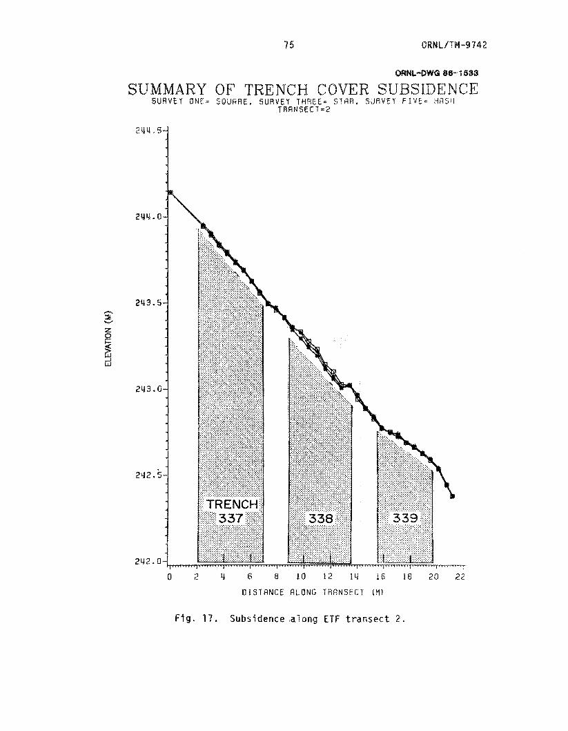
2 Y l d . O
243.5 .cI
v x z t 0
2 d
2Y3.0
2Y2.k
F i g . 17. Subsidence along ETF t ransect 2.
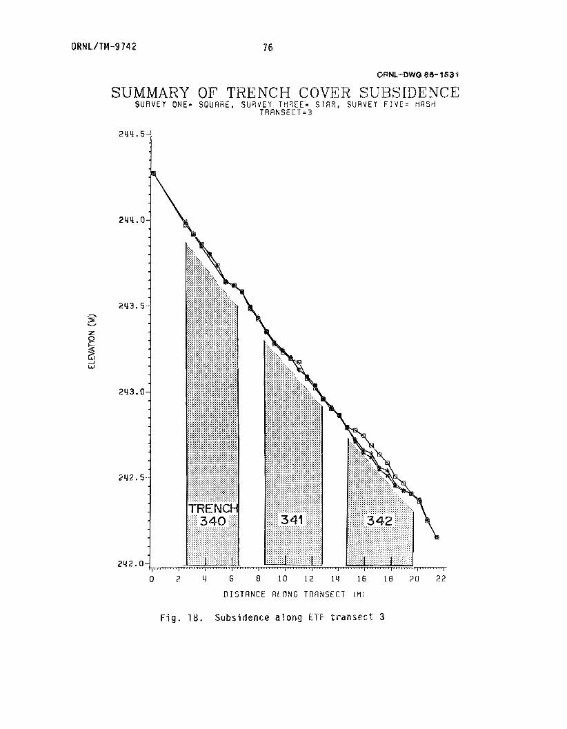
SUMMARY OF TRENCH COVER SUBSIDENCE S U R V E Y ONE= S Q U A R E , S l l R V E Y T H R E E = SIFIR, SURVEY F I V E - H R S H
T R R N S E C 'T = 3
2 U Y . 5
2Y2. a{p 0 2 4 6 o i o 12 i u 16 i a 2 0 2 2
0 I S T R N C E A L O N G T R A N S E C T (MI
F i g . 18. Subsidence along ETF t r a n s e c t 3
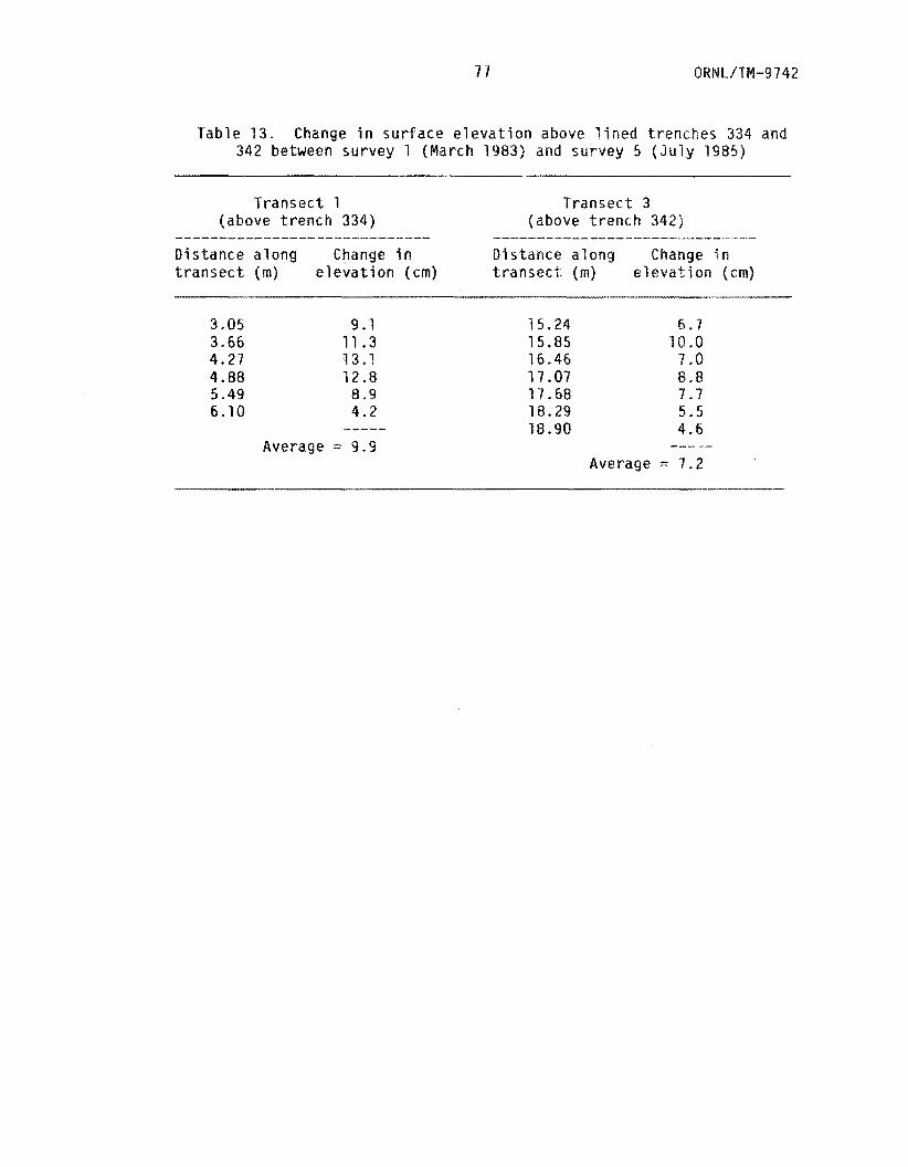
Tab le 13 . Change i n s u r f a c e e l e v a t i o n above l i n e d t renches 334 and 342 between su rvey 1 (March 1983) and su rvey 5 ( J u l y 1985)
T r a n s e c t 1 T r a n s e c t 3 (above t r e n c h 334) (above t r e n c h 342)
D i s t a n c e a l o n g Change i n D i s t a n c e a l o n g Change i n t r a n s e c t (m) e l e v a t i o n (cm) t r a n s e c t (m) e l e v a t i o n (cm)
-1-111 --------- ---- __--- I---- -_-- ^__l___l____.___l_ . _I.-
3.05 9.1 3.66 11.3 4.27 13.1 4.88 12.8 5 -49 8.9 6-10 4.2 -----
Average = 9.9
15.24 6.7 15.85 10.0 16.46 7 .Q 17.07 8.8 17.68 9.7 18.29 5.5 18.9Q 4.6
-- Average = 7.2
O R N L/T# -9 7 42 78
s u r f a c e o f t h e waste. Th is s t r e t c h i n g and mo ld ing o f t h e Hypalon cover
has r e s u l t e d i n a gradual s e t t l e m e n t o f t h e o v e r l y i n g s o i l t h a t cou ld
be de tec ted i n t h e subsidence surveys, Am obvious method o f c o r r e c t i n g
t h i s problem would be t o add s o i l f i l l t o t h e waste t r e n c h prjor t o
i n s t a l l i n g t h e Wypalon cover , T h i s would a c t as a smooth s u r f a c e and
preven t punc tu re o f t h e Wypalon under t h e we igh t o f t h e o v e r l y i n g s o i l
cover ,
U n l i k e l i n e d t renches 334 and 342, l i n e d t r e n c h 338 has n o t
e x h i b i t e d such n o t i c e a b l e cove r subsidence ( F i g . 17) . A s desc r ibed i n
Sect . 4.1, t h i s t r e n c h was f i l l e d w i t h t h e con ten ts a f waste ba les t h a t
had come a p a r t d u r i n g t h e i r approximate onc-year s to rage t i m e i n t r e n c h
334 ( f i g . 2 ) " When f i l l e d w i t h t h e con ten ts o f waste ba les , t r e n c h 338
had a much l e s s i r r e g u l a r t o p su r face , which c o u l d serve as a smoother
f o u n d a t i o n f o r t h e Wypalon cover . As a r e s u l t , t h i s t r e n c h cover- has
performed more l i k e those o f t h e g rou ted and c o n t r o l t renches than l i k e
those o f t h e o t h e r two l i n e d t renches. Thus two o f t h e t h r e e l i n e d
t renches have e x h i b i t e d i n i t i a l cover subsidence, and i t remains t o be
seen whether t h e subsidence w i l l c o n t i n u e o r whether i t w i l l g r a d u a l l y
cease as t h e l i n e r s conform t o t h e t o p s u r f a c e o f t h e waste .
I n t h e case o f t h e t h r e e c o n t r o l t renches, t h e t o p s u r f a c e o f t h e
waste was a g a i n i r r e g u l a r , s i m i l a r t o t h a t o f l i n e d t renches 334 and
342. Mhen t h e s o i l cove r was added, t h e e a s i l y a c c e s s i b l e v o i d spaces
were immediate ly f i l l e d as t h e compacted cove r was b u i l t up t o t h e
d e s i r e d 30 cm depth. As a r e s u l t o f t h i s i n i t i a l f i l l i n g o f a p o r t i o n
o f t h e upper t r e n c h v o i d space, t h e r e has been no detectd&le subsidence
o f t h e cover ove r t h e t h r e e c o n t r o l t renches. Only long- term
79 ORNL/TM-9742
moni to r ing w i l l determine whether water-Induced movement o f s o i l i n t o
voids loca ted deeper i n the t renches w i l l even tua l l y cause subsidence
problems over t h e c o n t r o l trenches.
The top sur face o f t he th ree grouted trenches was character ized as
smooth and firm a f t e r g rou t s e t . The s o i l cover over these trenches
has e x h i b i t e d no de tec tab le subsidence and w i l l l i k e l y no t unless l a rge
cracks develop i n the grout-waste ma t r i x . Even w i t h t h i s u n l i k e l y
scenario, t h e vo id space between waste bales i s f i l l e d w i t h grout ,
which w i l l i n h i b i t s o i l movement and keep cover subsidence t o a
minimum. From the 2-year survey, cement-bentonite g rou t i ng appears t o
be an e x c e l l e n t method o f p revent ing i n i t i a l caver subsidence over
l o w l e v e l waste d isposal trenches, and more t ime i s needed t o evaluate
the ex ten t o f t he observed subsidence over the l i n e d trenches.
QRNL/TM-9742 80
6 . ~ U ~ M A ~ Y AND CONCLUSIONS
Over t h e p a s t 40 years, t h e s tandard ethod o f d i s p o s i n g o f
l o w - l e v e l r a d i o a c t i v e waste a t DOE defense waste s ' l t e r has been sha l l ow
l a n d b u r i a l . A t ORWL, t renches a r e excavated t o a depth approx ima te l y
0,5 m above t h e ~ ~ ~ i ~ u m observed groundwater t a b l e i n t h e area , waste
and/or waste packages a r e p laced i n the t rench , and an approx ima te l y
l -m- th i ck s o i l cove r i s p laced o v e r each t r e n c h when i t i s f u l l . Very
few changes have been made i n t h i s o p e r a t i n g procedure, and f o r t h e
most p a r t i t has proved t o be a s a t i s f a c t o r y waste d i s p o s a l method. I n
a few ins tances , p a r t i c u l a r l y where o l d e r groups o f t renches a t lower
e l e v a t i o n s a r e i n v o l v e d , t h e r e have been r e p o r t s o f r a d i o n u c l i d e
m i g r a t i o n f rom t h e t renches ( p a r t i c u l a r l y 'OSr and
r e t r o s p e c t , a p p l i c a t i o n o f some improved sha l l ow l a n d b u r i a l t echn ique
o r use o f an a l t e r n a t e s i t e would l i k e l y have reduced o r even prevented
t h e p resen t " l e a k i n g t r e n c h " o r waste l e a c h i n g s i t u a t i o n .
3 H) and, i n
The purpose o f t h i s s tudy has been t o examine two improved sha l l ow
l a n d b u r i a l p r a c t i c e s ; t r e n c h g r o u t i n g p r i a r t o s o i l cove r emplacement,
and t r e n c h l i n i n g us ing a s y n t h e t i c impermeable l i n i n g m a t e r i a l . I n
1981 and 1982 n i n e exper imenta l t renches were excavated, f i l l e d w i t h
ba les o f l o w - l e v e l compacted waste generated a t ORNL, and t r e a t e d ( o r
n o t ) acco rd ing Lo t h e ETF exper imenta l p l a n (Boegly and Davis 1983).
This r e p o r t examines t h e performance o f t h e two t r e n c h t rea tmen ts and,
where p o s s i b l e , makes a comparison w i t h t h e u n t r e a t e d c o n t r o l
t renches. I n a l l cases, t h e t rea tmen t e v a l u a t i o n exper iments have been
designed t o i n v e s t i g a t e t h e a b i l i t y o f t h e improved p r a c t i c e s t o
p r e v e n t water-waste c o n t a c t ,

81 QRNL/T#-9742
A s a r e s u l t o f t h e e v a l u a t i o n exper iments desc r ibed i n t h i s
r e p o r t , t h e f o l l o w i n g conc lus ions concern ing t h e g rou ted and l i n e d
t renches have been reached.
1. Standing wa te r was observed i n a l l n i n e exper imen ta l t renches ( b o t h
t r e a t e d and c o n t r o l ) ; however, depth o f wa te r and wa te r l e v e l
f l u c t u a t i o n p a t t e r n s o v e r t h e approx ima te l y 3-year s tudy p e r i o d
d i f f e r a c c o r d i n g t o t h e t y p e o f t rea tmen t .
i n t r a t r e n c h w e l l s i n t h e t h r e e g rou ted t renches con ta ined o n l y a
sma l j amount o f water , and no f l u c t u a t i o n p a t t e r n was apparent
(Fig, 10). A t t h e o t h e r extreme, t h e t h r e e l i n e d t renches
con ta ined up t o 1.5 m o f s t a n d i n g water , which appeared t o
f l u c t u a t e seasona l l y (Figs. . 4 t h rough 5), b e i n g h i g h e s t i n t h e
w i n t e r months. The t h r e e c o n t r o l t renches were observed t o c o n t a i n
w a t e r on s e v e r a l occasions ( F i g s . 7 t h rough 9 ) ; t h i s i n t r a t r e n c h
wa te r seemed t o &e d i r e c t l y c o r r e l a t e d w i t h t h e p rev ious 5-day
p r e c i p i t a t i o n t o t a l s (Tab le 5), i n d i c a t i n g t h a t t h e wa te r was
p r o b a b l y t r a n s i e n t i n n a t u r e and r a p i d l y d r a i n e d f r o m t h e t rench .
Thus none o f t h e i n t r a t r e n c h w e l l s remained a b s o l u t e l y d r y o v e r t h e
m o n i t o r i n g p e r i o d .
Fo r example,
2. Water pump-out t e s t s conducted on t h e t h r e e l i n e d t renches d i d n o t
suppor t t h e o r i g i n a l hypo thes i s t h a t t h e l i n e r s were w a t e r t i g h t .
W i t h i n t h r e e months o f b e i n g pumped d r y o f i n t r a t r e n c h water , a l l
t h r e e t renches c o l l e c t e d w a t e r t o a l e v e l a t o r above t h e p r e t e s t
e l e v a t i o n . I n a d d i t i o n , t h e r e was a ve ry n o t i c e a b l e i n c r e a s e i n
i n t r a t r e n c h wa te r l e v e l s r e s u l t i n g f rom t h e heavy s torm a c t i v i t y
t h a t occu r red t h e f i r s t week i n May 1984.
ORH L/TM -9 7 4 2 82
3. Water pump-in t e s t s conducted on t h e t h r e e l i n e d t renches aga in
i n d i c a t e d t h a t t h e l i n e r was l e a k i n g . A f t e r d e l i v e r y o f 6624,
7191, and 11,809 L o f waker t o l i n e d t renches 342, 338, and 334,
r e s p e c t i v e l y , t h e i n t r a t r e n c h wa te r l e v e l s r a p i d l y subsided t o t h e
p r e t e s t e l e v a t i o n s ( F i g , 1 4 ) , i n d i c a t i n g leakage. In a d d i t i o n ,
nearby m o n i t o r i n g w e l l s ( w i t h i n 2 m o f t h e t r e n c h s i d e w a l l s ) were
observed t o show a r a p i d i nc rease i n w a t e r e l e v a t i o n , f u r t h e r
s u p p o r t i n g t h e l e a k i n g l i n e r scenar io .
4 . F i e l d measurements o f h y d r a u l i c conduct v i t y i n t h e t h r e e grouted
and t h r e e c o n t r o l exper imenta l t renches i n d i c a t e d t h a t f l o w OS
wate r th rough t h e grout -waste b a c k f i l l s 2 t o 3 o r d e r s o f
magnitude ( K = IO-' t o
th rough t h e c o n t r o l t renches ( K = lo-.' t o m / s ) . Th i s
reduced h y d r a u l i c c o n d u c t i v i t y o r a b i l i t y o f wa te r t o f l o w th rough
t h e waste t renches o f f e r s a h i g h e r degree s f h y d r o l o g i c i s o l a t i o n
f o r waste s t o r e d i n t h e g rou ted t renches.
m/s) lower t han f l o w o f wa te r
5 . The unconf ined compressive s t r e n g t h o f t h e g r o u t specimens showed
a s i g n i f i c a n t i n c r e a s e between subset 0 ( 7 4 c u r i n g t i m e ) and
subset 1 (4-month c u r i n g t i m e ) and has been a t t r i b u t e d 'ks t h e
i nc reased c u r i n g t i m e . No f u r t h e r changes i n compressive s t r e n g t h
have been observed th rough month 15. T e s t i n g of l i n e r t e n s i l e
s t r e n g t h and l i n e r punc tu re r e s i s t a n c e i n d i c a t e d t h a t aga in no
s i g n i f i c a n t changes have occu r red i n these eng ineer ing p r o p e r t i e s ,
w i t h t h e p o s s i b l e excep t ion o f t e n s i l e s t r e n g t h a t month 1 5
83 QRNL/TM-9742
(subset 3 ) . Add i t i ona l sampling, as scheduled i n Table 11, w i l l
enable a more ex tens ive eva lua t i on o f any r a p i d changes i n g rou t
and l i n e r p r o p e r t i e s w i t h age,
6. Trench cover subsidence surveys i n d i c a t e d t h a t o n l y two trenches
( l i n e d t rench 334 and l i n e d t rench 342) have e x h i b i t e d cover
subsidence. The subsidence was on t h e order o f 7 .2 t o 9.9 cm
(Table 13) and represented a se t t lement o f approximately 2-3% o f
t h e t o t a l t rench depth i n a 2-year per iod . The reason f o r t he
subsiidence over these p a r t i c u l a r t renches was be l ieved t o be t h e
s t r e t c h i n g o f t h e Hypalon over the i r r e g u l a r t o p sur face o f t h e
waste, Only cont inued mon i to r i ng w i l l determine whether subsidence
over these t w o t renches cont inues o r w i l l cease as the f a b r i c
conforms t o t h e shape o f t h e waste.
t renches have shown any i n d i c a t i o n o f cover subsidence.
None o f t h e remaining seven

Q RN I.. /Tbl -9 7 4 2 84
REFERENCES
Arora, t i . S., D. 0. H u f f , 0. S . Nard, and 0. PI. Sealand. 1981. An
assessment o f t h e effect o f a bentonite seal on groundwater
storage in underlying w a s t e disposa l trenches a t Oak Ridge
National Labora to ry . ORNL/TM-?416.
Baker, W . H . ( e d . ) . 1982. Proceedings o f the Conference on G r o u t i n g
in Geotechnical Engineering. Sponsored by the Geotechnica l
Engineering Division o f t h e American Society o f C i v i l Engineers in
cooperation Edlith A S & E / A I M E Underground Technology Research
Council. New Orleans, Louisiana, February 10-12, 1982. A X E 345
East 47th St. New York, New York.
Beach, I - I . J . 1961. Improved bentoni%e cemesrts t h r o u g h partial
acceleration. J . Pet. Technol . Trans., Am. Inst. Min. Metall.
Pet . E n ¶ . 222~923-926.
Blacklock, J , R . , R. C . J o s h i , and P. J . Inlright. 1982. Pressu re
injection grouting o f landfills using lime and flyash. pp.
7013-721. IN Proc. o f the Conf . on Grouting in Geotechnical
Engineering. American Society o f C i v i l Englneers, New York.
Eoegly, W . J , , Jr. and E. C. Davis. 1983. Design and construction o f
a low-level waste shallow land burial experimental facility.
ORNL/TM-3847.
Buelt, J . L. and S. M. Barnes. 1981. A comparative evaluation o f
nactivc uranium mill tailings piles. pp.
Mill Tailings Management, Proceedings o f the
orado State University, Fort Collins,
liner materials f o r
713-727. IN Uranium
Fourth Symposium, Co
Col oracla.

85
Caron, C. 1982. The s t a t e o f g r o u t i n g i n t h e 980 ' s . pp. 346-358. IN
Proceedings o f t h e Conference on Grou t ing i n Geotechnica l
Engjneer ing, American S o c i e t y o f C i v i l Engineers, Hew York.
Davis, E . C . , W . J . Boegly, J r . , E. R. R o t h s c h i l d , E!. P. Spald ing,
M . 0. Yaughan, C . S . Haase, 8. 0, H u f f , S . Y. Lee, E . C. Wal ls , J .
8 , Newbold and E . D. Smith. 1984. S i t e
techniques used a t a l o w - l e v e l waste sha l
demonstrat on f a c i l i t y . QRNL/TM-¶146.
Davis, E. C . and R. 6. S t a n s f i e l d . 1984. Des
French d r a i n for groundwater d i v e r s i o n i n
s i x a t t h e Oak Ridge N a t i o n a l Labora to ry .
c ha r a c t e r i za t i on
ow l and b u r i a l f i e l d
gn and c o n s t r u c t i o n o f a
s o l i d waste s to rage area
ORNL/TH-9014 (.
Fung, R. 1980. P r o t e c t i v e b a r r i e r s f o r conta inment o f t o x i c m a t e r i a l s .
Noyes Data Gorp., Park Ridge, N . 3 .
Geswein, A. L . 1975, L i n e r s f o r l a n d d i s p o s a l . SW-137. USEPA,
Washington, D.C.
Handy, R. L . 1979. Elementary fundamental p r i n c i p l e s of g r o u t i n g .
p p . 2-65. IN Proceedings o f t h e Nov. 5-7, 1979, Grou t ing
Conference, Colorado School o f Mines, Golden, Colorado.
Herndon, J . , and T. Lenahan. 1976. G r o u t i n g of s o i l s Val . 1, A s t a t e
o f t h e a r t r e p o r t . FHWA-RD-76-26 ( P B 259 043). U . S . Department o f
T r a n s p o r t a t i o n , Washington, D . C .
Hvors lev, W . S . 1951. Time l a g and s o i l p e r m e a b i l i t y i n groundwater
obse rva t i ons . B u l l . 36. Waterways Exper iment S t a t i o n , U . S . Army
Corps o f Engineers, Yicksburg, Miss.
ORNL/TM-9742 86
K a r o l , R . W . 1982. Chemical g r o u t s and t h e i r p r o p e r t i e s .
pp. 359-357. I N Proceedings o f t h e Conference on G r o u t i n g i n
Geo techn ica l Eng ineer ing , American S o c i e t y o f C i v i l Engineers,
New Yark.
Kays, W . 8. 1977. C o n s t r u c t i o n o f l i n i n g s f a r r e s e r v o i r s , tanks, and
p o l l u t i o n c o n t r o l f a c j l i t i e s . W i ley , Mew York.
Lee, J - 1974. S e l e c t i n g membrane pond l i n e r s . Pollut- Eng, 6:33-40 .
Morgan, 8. E.. and G. K . Dumbauld. 1951. A m o d i f i e d l o w - s t r e n g t h
cement. Trans, Am, Ins t . Mlin. M e t a l l . Pet , Eng. 192:165-178,
Morgan, 0 . E . and C;, K . Oumbauld, 1954, Bentonite cement p r o v i f i g
s u c c e s s f u l i n perrnanent-type squeeze o p e r a t i o n s . World Oil
Vol . 220,
Newbold, J . D., and H. A . Bogle, 1984. An automated system f o r
m o n i t o r i n g groundwater l e v e l s a t an exper imen ta l l o w - l e v e l waste
d i s p o s a l s i t e . ORNL/TM--9007.
Smith, B K. 1975. Cementing, i v l i l l e t I nc . , D a l l a s , Texas.
S p a l d i n g B. P . 1984. F i e l d demons t ra t i on o f i n s i t u t r e a t m e n t o f
b u r ed l o w - l e v e l r a d i o a c t i v e s o l i d w a s t e w i t h c a u s t i c soda and
soda ash t o irnmobi l i m e "Sr. BRNL/TM-8990.
Tamurd, T. 1957. Disposal o f r a d i o a c t i v e w a s t e s by h y d r a u l i c
f r a c t u r i n g P a r t I V . ChemScal development o f waste-cement m i x t u r e s .
Nuc l . Eng. 5:477-485.
U.S. N u c l e a r R e g u l a t o r y Commission (USNRC). 1981. D r a f t environme
impac t s ta temen t on 10 CFR P a r t 61, " L i c e n s i n g Requirements f o r
Land D isposa l o f R a d i o a c t i v e Mantes". NUREG-0782, Vol . 2, pp. 3-39.
Vaughan, N. D . , C. S . Haase, D, D . Huff, S. Y . Lee, and E . C . Malls.
1982, Fie ld demonstration o f improved shallow land bu r i a l
p r a c t i c e s f a r low-level r ad ioac t ive so l id waste: PreSimlnary s i t e
chasac te r i r a t i o n and progress r e p o r t . Q R ~ L / T M - 8 4 7 ~ .

O R ~ L ~ ? ~ -97 4 2
INTERNAL OISTRlBUTION
1 , T. L. Ashwood 2 , S. I . Auerbach 3 . W , J. Boegly, J r . 4. R. 0. Clapp 5, A . S , Croff 6. N . H. Cutshall
7-11. E . C . Davis 1 2 . L. R . Dole 13. L, 0. Eyman 14, C . S , Haase 1 5 , S. 6. Hildebrand 16. F. J. Homan 17. C. Irl. Kendrlck 18. R . H, Ketelle 19. L. C , Lasher 20. S. Y . Lee 21. R . S . Lowrie 22* L , E . HcMeese 23. L. J . Mezga
70.
71.
1 2 .
73.
74.
75.
76.
71.
18.
24. T. E . Myrick 25. W . W . P i t t 26. 0. E . Reichle 27. 28. 29. 30.
31 -35 . 36-45.
46. 41. 48. 49.
50-64. 65-66.
67. 6 8 . 69.
C. R . Richmond T. H. Row E. D. Smith D. K . Solomon 6. P. Spalding L. E. Stra t ton J , Switek T. Tarnura 6 . T. Yeh Central Research L i b r a r y E50 Library Laboratory Records Dept. Laboratory Records, BRNL-RC ORNL Patent Section O R N L '6-12 Technical Library
EXTERNAL DISTRIBUTION
H. Barainca, Program Irlanager, Low-Level Waste Management Program, U.S. Department of Energy, 550 Second S t r e e t , Idaho Fa l l s , ID 83403 J , J . ELlakeslee, Program Manager, Nuclear Waste Processing, Rocky Flats Plant, Rockwell Internat ional , P.0. Box 464, Galden, CO 80401 J . Thomas Callahan, Associate Director, Ecosystem Studies Program, Room 336, 1850 G S t r e e t , N W , National Science Foundation, Nashington, DC 20550 T . C . Chee, R&D and Byproducts Division, DP-123 ( G T N ) , U.S. Department of Energy, Washington, DC 20545 A . T. Clark, J r . , Advanced Fuel and Spent Fuel Licensing Branch, Divisclrn o f Fuel Cycling and Material Safety, 396-525, U. S. Nuclear Regulatory Commission, 7915 Eastern Avenue, S i l v e r Spring, MD 20910 Peter Colombo, Group Leader, Nuclear Haste Research, Brookhaven National Laboratory, Bldg. 701, Upton, N Y 11973 E . f . Cont l , Of f i ce of Nuclear Regulatory Research, Nuclear Regulatory Commission, HS-1135-SS, Washington, DC 25555 J. E . Dleckhoner, Acting Director, Operations and Traff ic Dlvislon, DP-122 (GTN), U.S. Department o f Energy, Washington, DC 20545 Bob Dodge, Low-level Waste Management Program, EG&G Idaho, I n c . , P. 0. Box 1625, Idaho Fa l l s , ID 83415
0 R N L / lbl -9 7 4 2 90
79.
80.
81.
82.
$ 3 .
84.
85.
$ 6 .
87.
88.
89.
90.
91 .
92.
93.
94.
95.
96 .
97. 98.
G . J . Foley, Of f i ce o f Environ en ta l Process and Effec ts Research, U.S. Environmental P o t lec t ion Agency, 401 M S t r e e t , SW, RD-682, Washington, DC 20460 Carl Gertz, Director, Radioactive Maste Technology Divis ion, Idaho Operations O f f i c e , U * S . Department of Energy, 550 Second S t r e e t , Idaho F a l l s , ID 83401 C . R . Goldman, Professor of Limnology, Di rec tor of Tahoe Research Group, Division of Environmental S tud ie s , Universi ty
Director, West Valley P ro jec t Off ice , U . S . Department of Energy, P.0. Box 191, Mest Valley, NY 14171 J . W . Huckabee, Manager-, Eco log ica l S tudies Program, E l e c t r i c Power Research I n s t i t u t e , 3412 Hillview Avenue, P . O . Box 10412, Pa ls Alto, CA 94393 E. A . Jennr ich , Program Manager, Low-Level Waste Management Program, EG&G Idaho, I n c + , P . O . Box 1625, Idaho F a l l s , ID 83415 J . J . J i cha , Director, R&D and Byproducts Divis ion, DP--123 ( G T M ) , U . S . Department of Energy, Washington, DC 20545 E . A . Jordan, Low Level Waste Program Manager, D iv i s ion of Storage and Treatment Projects, NE-25 (GTN) , U.S- Department of Energy , Washington, DC 26545 George Y . Jordyl Director, O f f i c e of Program Analysis, Off ice of Energy Research, LR--30, 6-226, U.S. Department o f Energy , Washington, DC 20545 J . Howard K i t t e l , Manager, Off ice o f Waste Hanagernent Programs,
e National Laboratory, 9700 S . Cass Ave,, B l d g , 205, Argsnrae, IL 50439 L . T . Lakey, Waste I s o l a t i o n , Pac i f i c Northwest Laboratory, Richland, MA 99352 Leonard Lane, Los Alamos National Laboratory, P.B. Box 1663, Los Alamss, NM 87545 D. B. k c f a i r - e , Director, Off ice of Defense Waste and Byproducts Management, OQ-12 (GT ) , U.S. Department of Energy , Washington, DC 20545 Helen NcCammon, Direc tor , Ecological Research Divis ion, Off ice of Heal th a n d Environmental Research, Off ice of Energy Research, MS-E201, E R - 7 5 , Room € 4 3 3 , Department o f Energy, a%hington , BC 20545 ichae l McFadden, Waste Management, Albuquerque Operations f f i c e , U.S. Department o f Energy, Albuquerque, Nbl 37115
Edward O'Donnell, Division o f Radiat i oa Programs a n d Earth Sciences, U.S. Nuclear Regulatory Corn i ss ion , Mail Stop 1130 S S , Washington, DC 20555
on, Program Director , bdaste Management Program e l l I-lanford Operations, P.0. Box $00, Richland,
MA 99352 I r n i n Remson, Department o f A p p l i e d Earth Sciences, Stanford Universi ty , S tanford , C A 94305 Jackson Robertson, USGS, 410 National Center , Restsn, V A 22092 E . M. Romney, Universi ty o f Cal i fo rn ia , Los Angeles, 900 Veteran Avenue, Cos Angeles, C A 90024
a 9 Davis, CA 94616
91 O R ~ L / T ~ - 9 ~ 4 ~
99.
100.
101. 102*
103.
104.
105. 106.
107.
l o a .
109.
110.
11 1-1 37.
I l k k a Savolainen, Haste Management Sect ion, I n t e r n a t i o n a l Atomic Energy Agency, Wagramerstrasse 5, P. 0, Box 100, A-1400 Vienna, Aus t r i a R. J. Starmer, HLW Technical Development Branch, O f f i c e o f Nuclear M a t e r i a l Safety and Safeguards, Nuclear Regulatory Commission. Room 427-SS, Washington, OC 20555 M. T. Stewart, U n i v e r s i t y o f South F lo r i da , Tampa, FL 33620 J . G. Steger, Environmental Sciences Group, Los Alamos S c i e n t i f i c Laboratory, MS-K495, P.O. Box 1663, Los Alamos, NM 07545 R , J . Stern, D i rec to r , O f f i c e o f Environmental Compliance, MS PE-25, FORRESTAL, U.S. Department o f Energy, 1000 Independence Avenue, SW, Washington, OC 28585 J . A. Stone, Savannah R iver Laboratory, E . I . DuPont de Nemours and Company, Bldg, 773-A, Room E-112, Aiken, SG 29800 S. B. Upchurch, U n i v e r s i t y o f South F lo r i da , Tampa, F L 33620 Leonard H . Weinstein, Program D i r e c t o r o f Environmental B io logy, Cornel1 Un ive rs i t y , Boyce Thompson I n s t i t u t e f o r P lan t Research, I thaca, NY 14053 Raymond G. Wilhour, Chief , A i r P o l l u t i o n E f f e c t s Branch, C o r v a l l i s Envlronmental Research Laboratory, U.S. Environmental P ro tec t i on Agency, 200 SW 35th S t ree t , C o r v a l l i s , OR 97330 Frank J . Wobber, Eco log ica l Research D iv i s ion , O f f i c e o f Hea l th and Environmental Research, O f f i c e o f Energy Research, #S-E201, Department o f Energy, Washington, DC 20545 M. Gordon Wolman, The Johns Hopkilas Un ive rs i t y , Department o f Geography and Environmental Engineering, Bal t imore, M D 21218 Q f f i c e o f Ass i s tan t Manager f o r Energy Research and Development, Oak Ridge Operations, P. 0. Box E, U . S . Department o f Energy, Oak Ridge, TN 37831 Technical I n fo rma t ion Center, Oak Ridge, TN 37831