Embed Size (px)
Citation preview
Field Experience with Hydrogenics' Prototype Stack and System
for MW PEM electrolysis
Jan Vaes, February 17th, 2nd int. workshop on Durability and Degradation Issues in PEM
Electrolysis Cells and their Components, Freiburg
2
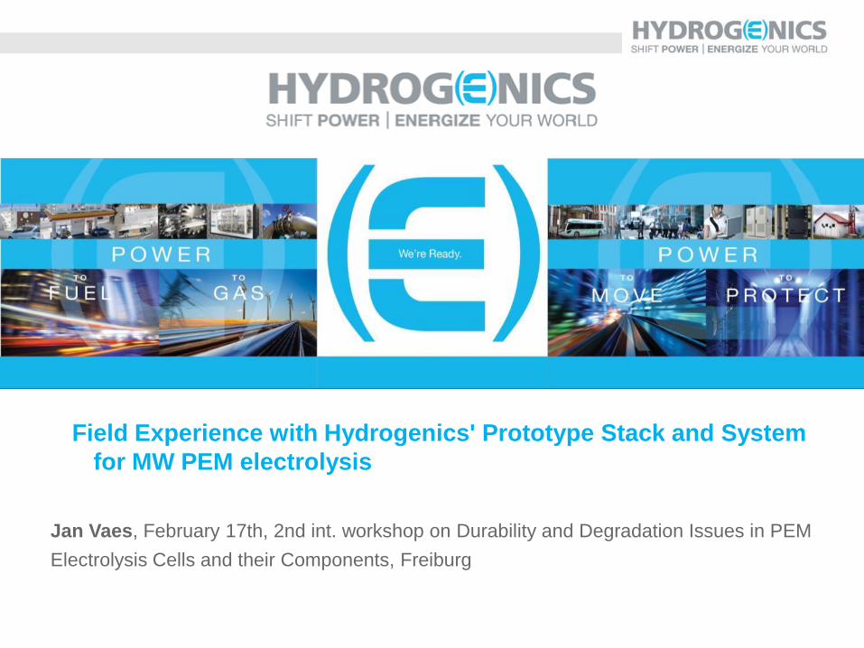
Hydrogenics in Brief
International structure Hydrogenics Corporation
Headquarter
Mississauga, Ontario, Canada
Since 1948
+/- 70 employees
Areas of expertise: Fuel cells, PEM electrolysis, Power-to-Gas
Previously: The Electrolyser Company, Stuart Energy
Hydrogenics Gmbh
Gladbeck, Germany
Since 2002
+/- 15 employees
Areas of expertise: Fuel cells, mobility projects,
Power-to-Gas
Hydrogenics Europe
Oevel, Belgium
Since 1987
+/- 70 employees
Areas of expertise: pressurized alkaline electrolysis,
hydrogen refueling stations, Power-to-Gas
Previously: Vandenborre Hydrogen Systems
In total: +/- 155 employees
Incorporated in 1995 [NASDAQ: HYGS; TSX: HYG]
More than 2,000 products deployed in 100 countries worldwide
Total revenues (2014): 45.5 Mio $
Over 70 years of electrolysis leadership
3
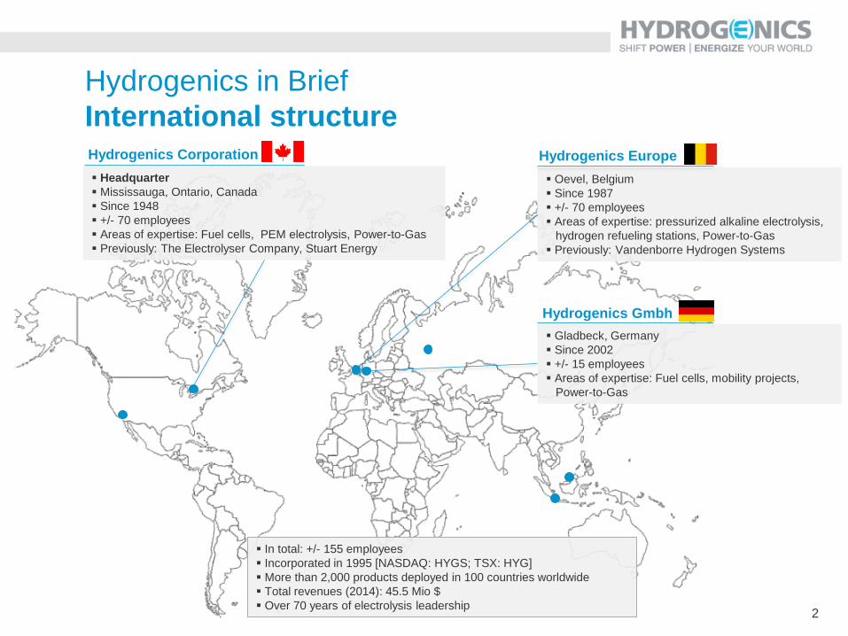
Hydrogen generation and Power-to-X routes
GAS GRID
Electrolysis H2 storage (optional)
POWER GRID
Power-to-Hydrogen
Power-to-Power
Wind turbine
Solar PV
CHP
Fuel cells
Methanation
Refuelling stations
Refineries
Chemical plants
Power-to-Gas
Hydrogen network Power network Gas network Liquid fuels network
SURPLUS OR LOW-COST
ELECTRICITY
Blending
O2 H2O
CO2
H2
Heat
Speciality chemicals
Ammonia
Power-to-Industry
Industry
Hydrogen Vehicles (FCEV)
Power-to-Mobility
Gas turbines
Low C02 fuels
Methanol
Power-to-Fuels
CNG
AWE
10-180
nm³/h
AWE
240
nm³/h
PEM/AWE
30 /210
nm³/h PEM
120
nm³/h
Hybalance
PEM
230 nm³/h
AWE
360 nm³/h
PEM
285
nm³/h
4
1500E PEM PLATFORM
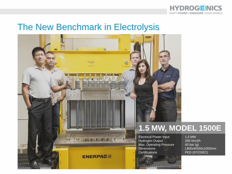
1.5 MW, MODEL 1500E Electrical Power Input 1.5 MW
Hydrogen Output 285 Nm3/h
Max. Operating Pressure 40 bar (g)
Dimensions L800xW550x1000mm
Certifications PED (97/23/EC)
The New Benchmark in Electrolysis
6
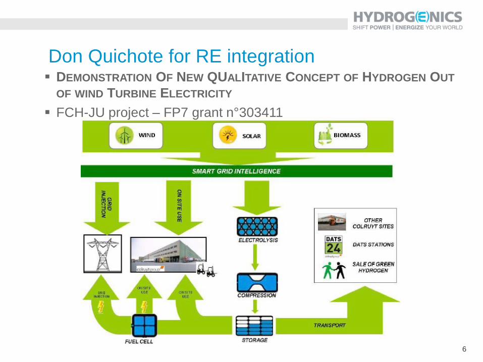
Don Quichote for RE integration DEMONSTRATION OF NEW QUALITATIVE CONCEPT OF HYDROGEN OUT
OF WIND TURBINE ELECTRICITY
FCH-JU project – FP7 grant n°303411
7
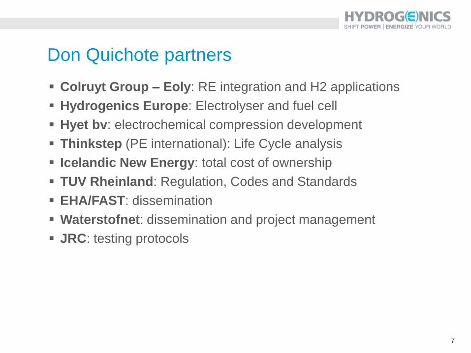
Don Quichote partners
Colruyt Group – Eoly: RE integration and H2 applications
Hydrogenics Europe: Electrolyser and fuel cell
Hyet bv: electrochemical compression development
Thinkstep (PE international): Life Cycle analysis
Icelandic New Energy: total cost of ownership
TUV Rheinland: Regulation, Codes and Standards
EHA/FAST: dissemination
Waterstofnet: dissemination and project management
JRC: testing protocols
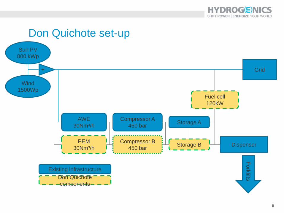
8
Fuel cell
120kW
AWE
30Nm³/h
PEM
30Nm³/h
Compressor A
450 bar
Compressor B
450 bar
Sun PV
800 kWp
Wind
1500Wp
+ Grid
Storage A
Storage B Dispenser
Fo
rklifts
Existing infrastructure
Don Quichote
components
Don Quichote set-up
9
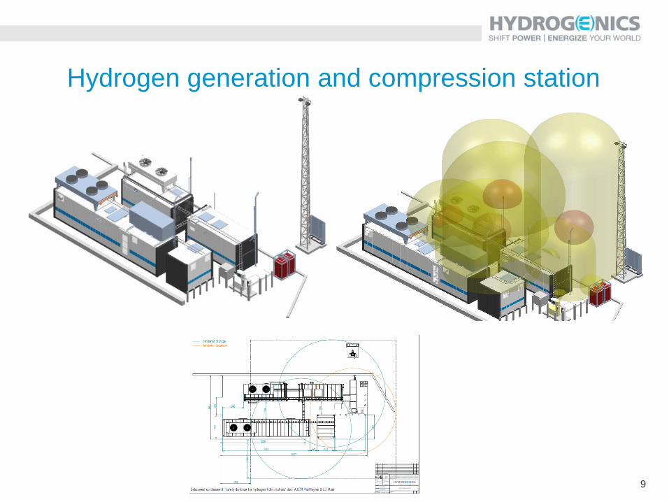
Hydrogen generation and compression station
10
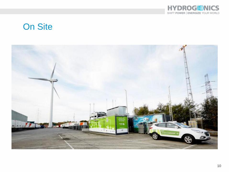
On Site
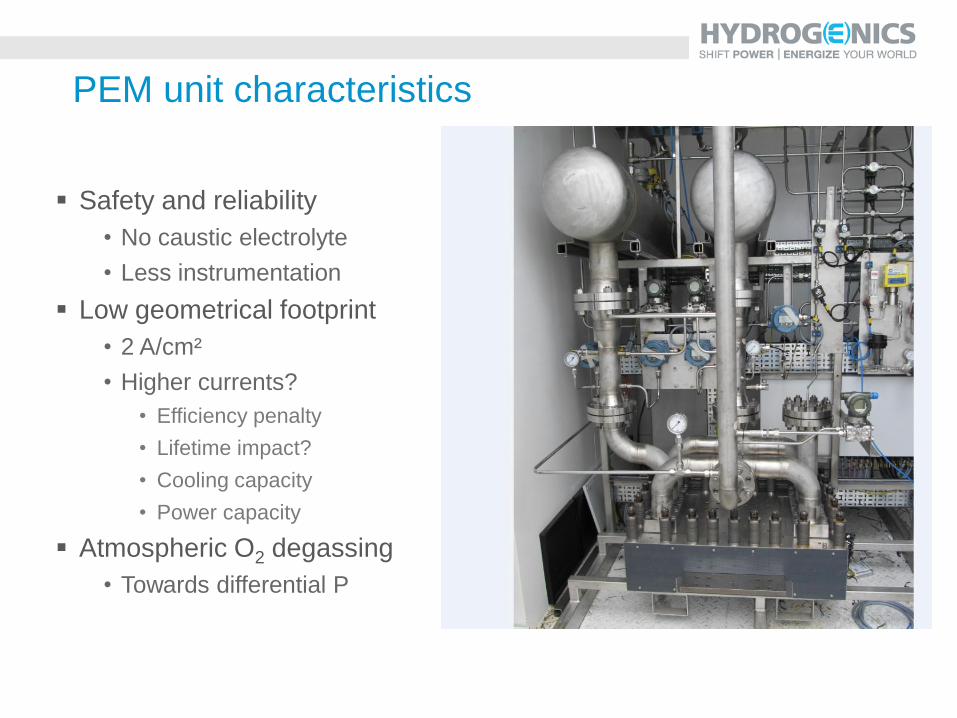
PEM unit characteristics
Safety and reliability
• No caustic electrolyte
• Less instrumentation
Low geometrical footprint
• 2 A/cm²
• Higher currents?
• Efficiency penalty
• Lifetime impact?
• Cooling capacity
• Power capacity
Atmospheric O2 degassing
• Towards differential P
12
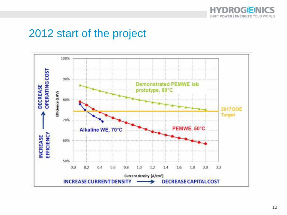
2012 start of the project
13
Don Quichote field results
14
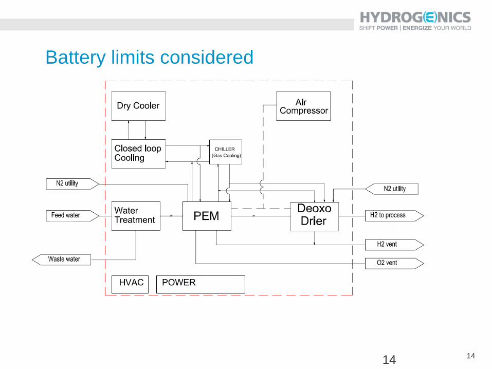
Battery limits considered
14
15
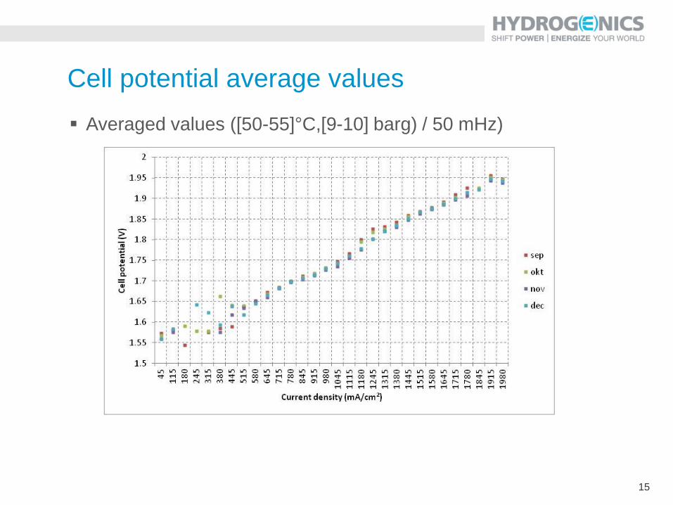
Cell potential average values
Averaged values ([50-55]°C,[9-10] barg) / 50 mHz)
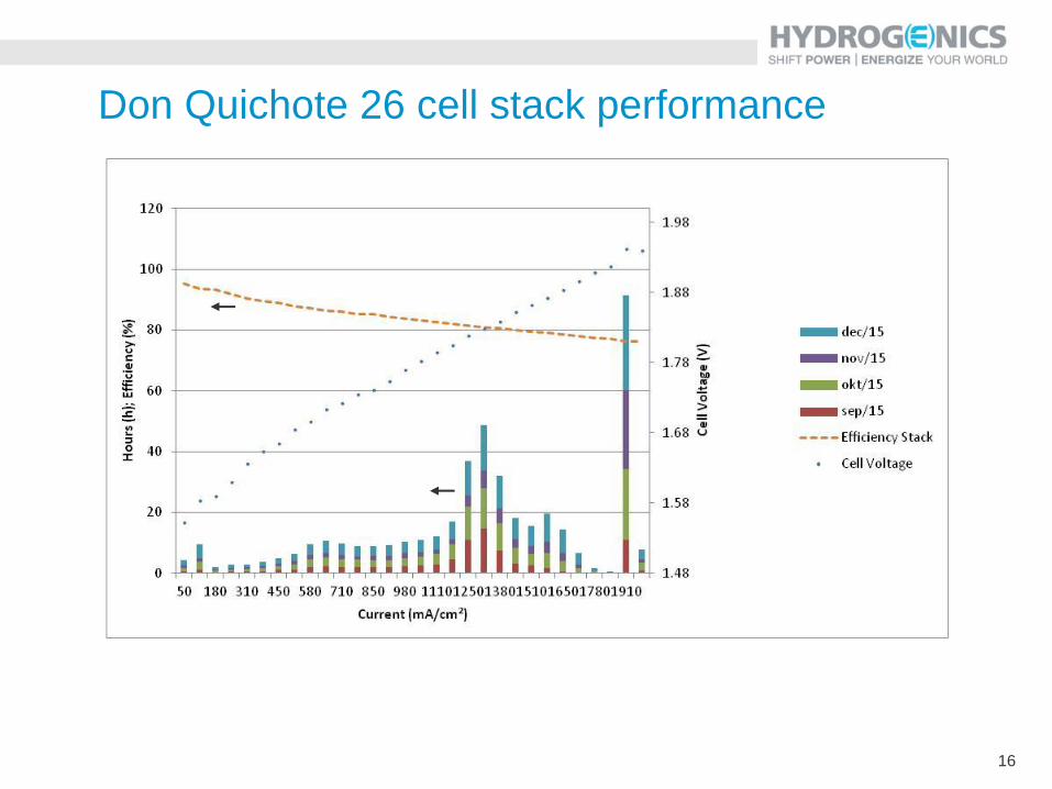
16
Don Quichote 26 cell stack performance
17
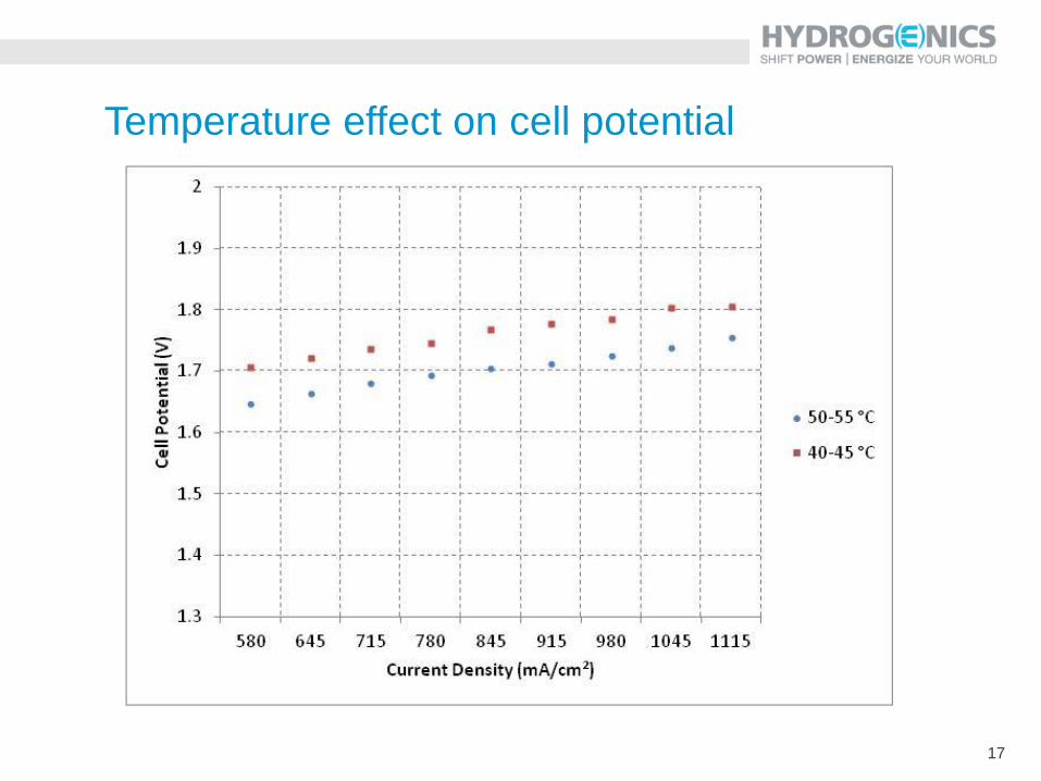
Temperature effect on cell potential
18
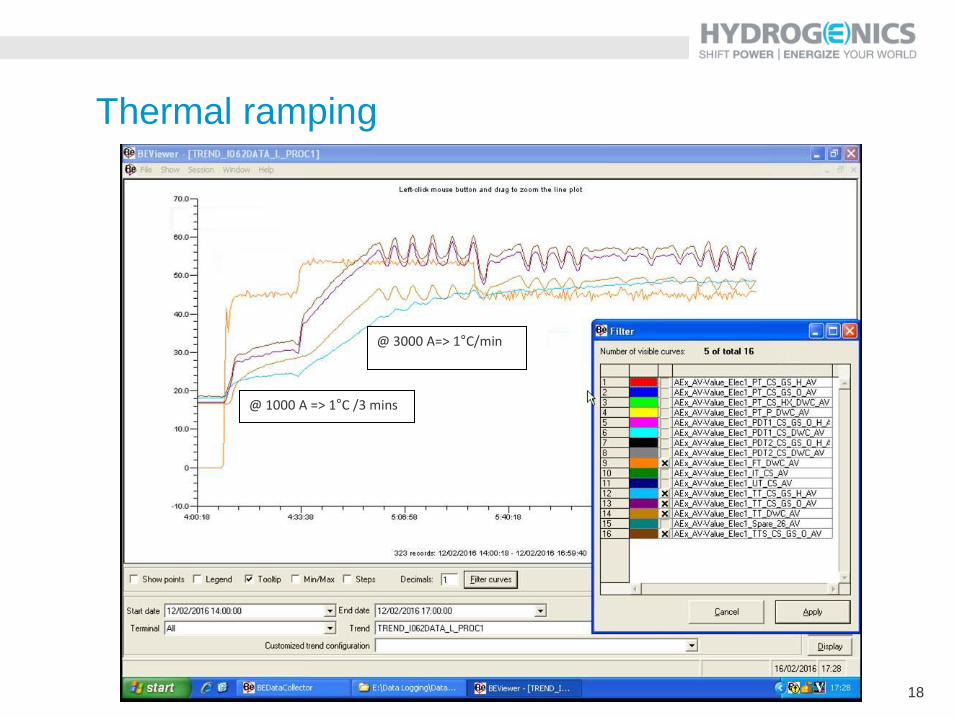
@ 3000 A=> 1°C/min
@ 1000 A => 1°C /3 mins
Thermal ramping
19
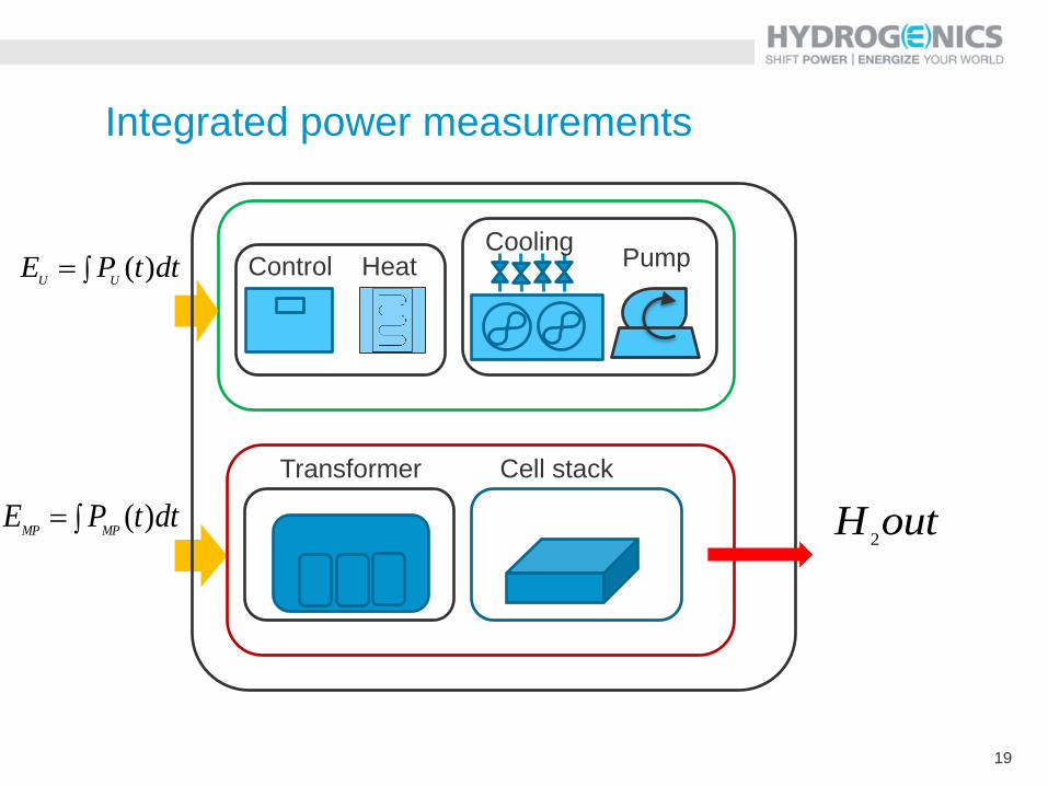
Integrated power measurements
dttPEUU
)(
dttPEMPMP
)(
Control Heat Cooling
Pump
Transformer Cell stack
outH2
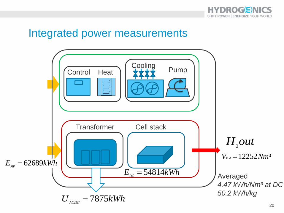
20
Integrated power measurements
kWhUACDC
7875
kWhEDC
54814
Control Heat Cooling
Pump
Transformer Cell stack
outH2
kWhEMP
62689³122522 NmVH
Averaged
4.47 kWh/Nm³ at DC
50.2 kWh/kg
21
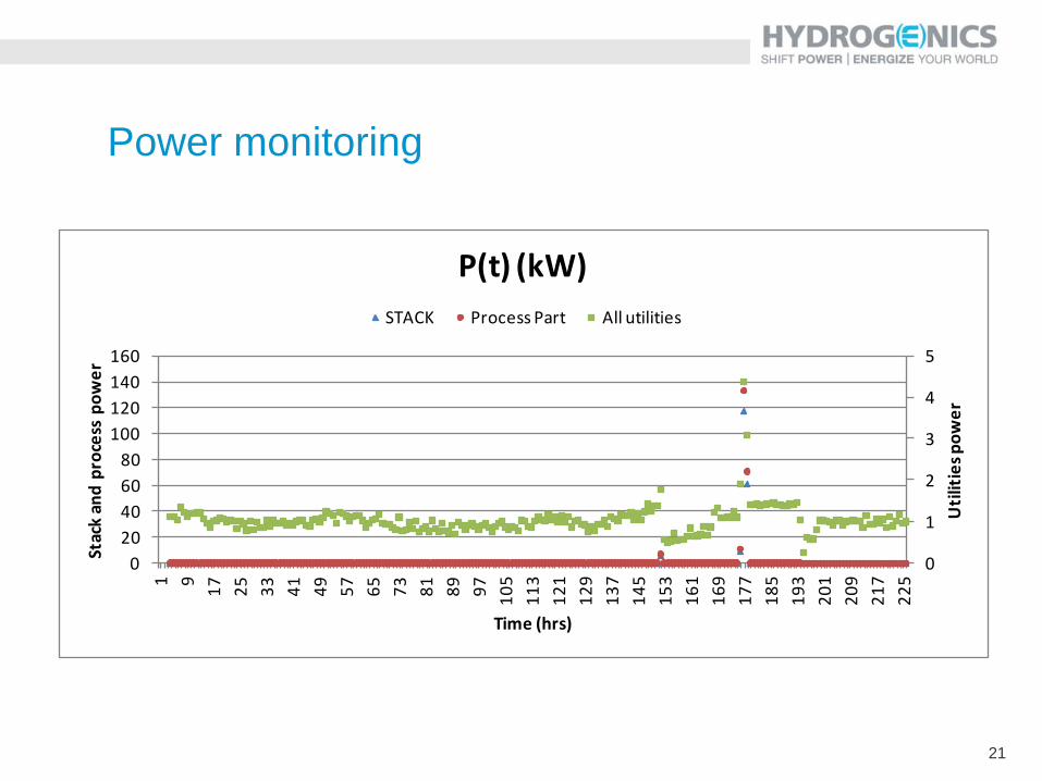
Power monitoring
0
1
2
3
4
5
0
20
40
60
80
100
120
140
160
1 9
17
25
33
41
49
57
65
73
81
89
97
10
5
11
3
12
1
12
9
13
7
14
5
15
3
16
1
16
9
17
7
18
5
19
3
20
1
20
9
21
7
22
5
Uti
litie
s p
ow
er
Stac
k an
d p
roce
ss p
ow
er
Time (hrs)
P(t) (kW)
STACK Process Part All utilities
22
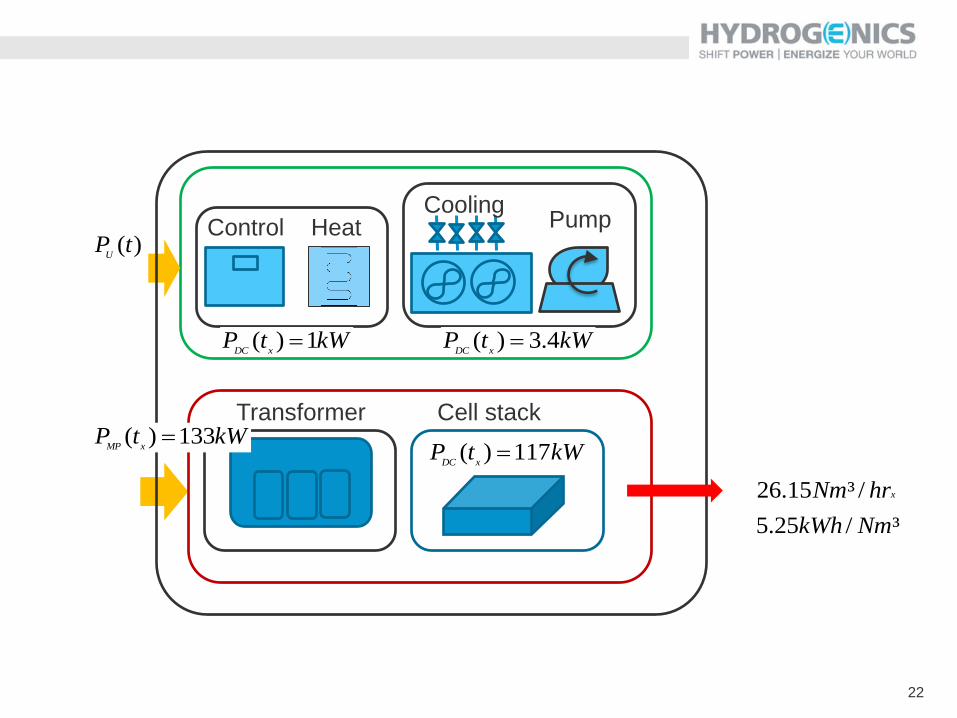
Control Heat Cooling
Pump
Transformer Cell stack
kWtPxDC
117)(
kWtPxDC
1)( kWtPxDC
4.3)(
kWtPxMP
133)(
)(tPU
³/25.5
/³15.26
NmkWh
hrNm x
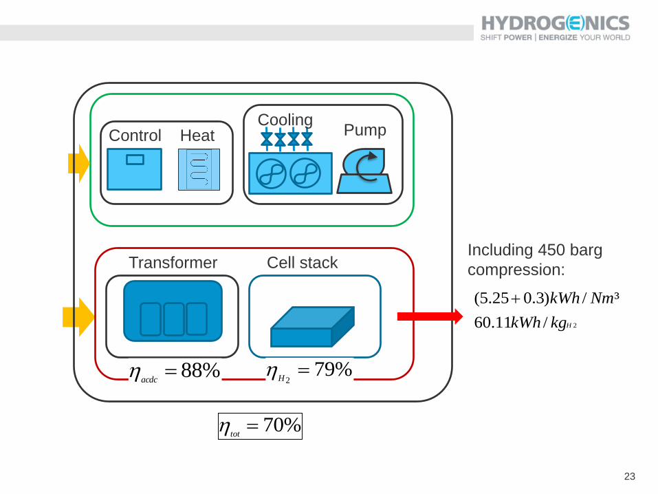
23
Control Heat Cooling
Pump
Transformer Cell stack
%88acdc
%792
H
%70tot
2/11.60
³/)3.025.5(
HkgkWh
NmkWh
Including 450 barg
compression:
24
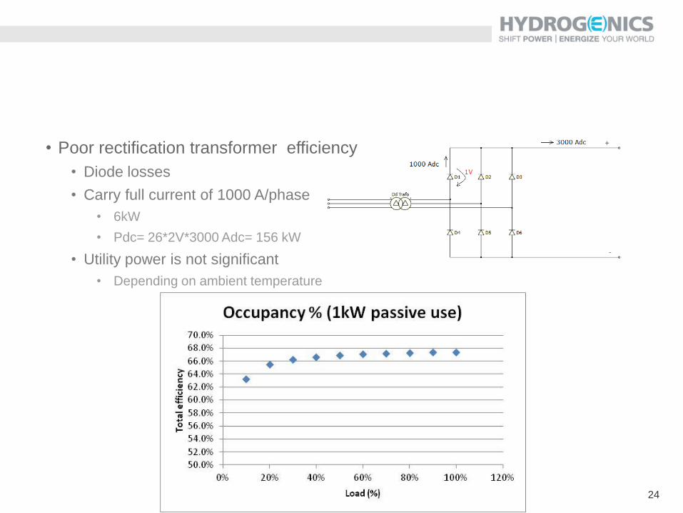
• Poor rectification transformer efficiency
• Diode losses
• Carry full current of 1000 A/phase
• 6kW
• Pdc= 26*2V*3000 Adc= 156 kW
• Utility power is not significant
• Depending on ambient temperature
25
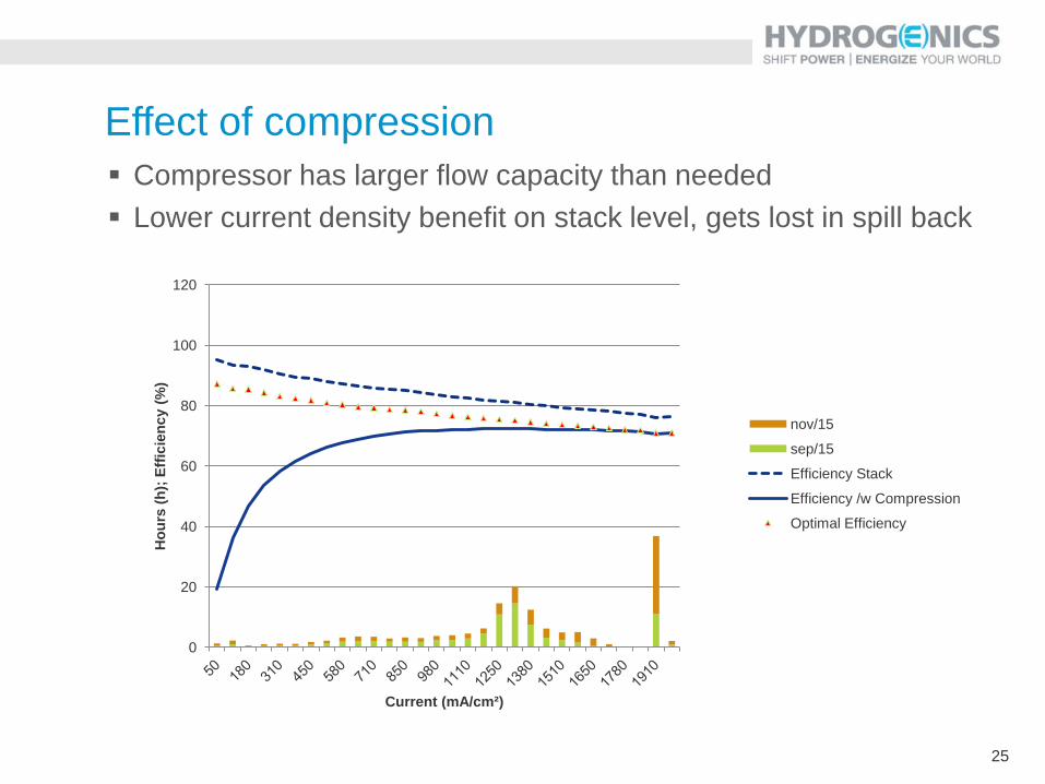
Effect of compression
Compressor has larger flow capacity than needed
Lower current density benefit on stack level, gets lost in spill back
0
20
40
60
80
100
120
Ho
urs
(h
); E
ffic
ien
cy (
%)
Current (mA/cm²)
nov/15
sep/15
Efficiency Stack
Efficiency /w Compression
Optimal Efficiency
26
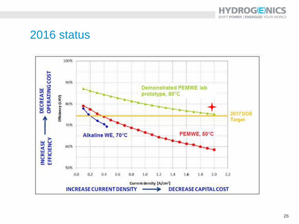
2016 status
PEM or AWE for Power to xyz ?
• Dynamic operation:
• PEM : 5-100% - nano porosity in membrane
• AWE: 20 -100 % range
• Micrometer scale porosity
• Cold start:
• N2- Purging / getting hydrogen out a given purity
• Smaller volume for PEM
• Limited current because of rise to operational temperature
• PEM: smaller ΔT required / smaller volume
• Overload regime, response times
• Power electronics and cooling are determining
• Size matters => limited ΔT for AWE
• Capex
• Similar € numbers > 5MW
• Site footprint smaller for PEM
• Opex
• Similar electricitiy consumption (~capex)
• Maintenance:
• known for AWE (2-10%)
• to be derisked for PEM (stack)
28
Ongoing MW PEM projects
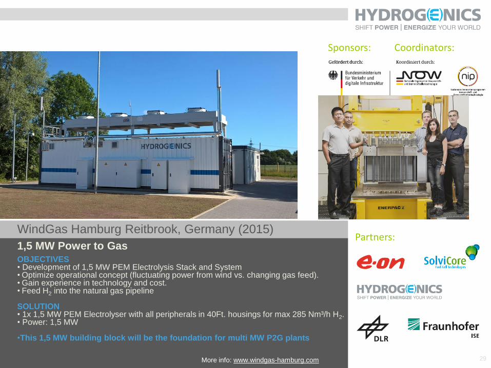
WindGas Hamburg Reitbrook, Germany (2015)
1,5 MW Power to Gas
OBJECTIVES • Development of 1,5 MW PEM Electrolysis Stack and System • Optimize operational concept (fluctuating power from wind vs. changing gas feed). • Gain experience in technology and cost. • Feed H2 into the natural gas pipeline SOLUTION • 1x 1,5 MW PEM Electrolyser with all peripherals in 40Ft. housings for max 285 Nm³/h H2. • Power: 1,5 MW •This 1,5 MW building block will be the foundation for multi MW P2G plants
Partners:
Sponsors: Coordinators:
29 More info: www.windgas-hamburg.com
30
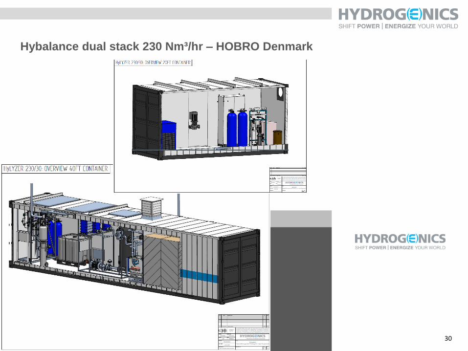
Hybalance dual stack 230 Nm³/hr – HOBRO Denmark
Lünen, Germany
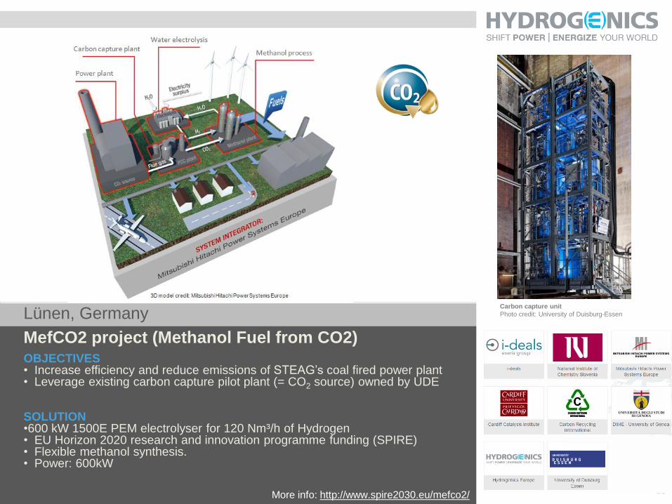
MefCO2 project (Methanol Fuel from CO2)
OBJECTIVES • Increase efficiency and reduce emissions of STEAG’s coal fired power plant • Leverage existing carbon capture pilot plant (= CO2 source) owned by UDE SOLUTION •600 kW 1500E PEM electrolyser for 120 Nm³/h of Hydrogen • EU Horizon 2020 research and innovation programme funding (SPIRE) • Flexible methanol synthesis. • Power: 600kW 31
Carbon capture unit
Photo credit: University of Duisburg-Essen
More info: http://www.spire2030.eu/mefco2/
32
Denis THOMAS
Business Development Manager Power-to-Gas
Mobile: +32 479 909 129
Email: [email protected]
Thank you for your attention !
Jan VAES
Technology Director
Mobile: +32 497 50 28 27
Email: [email protected]