Embed Size (px)
Citation preview
RPV and Primary Circuit Inspection
Field Experience with Lightweight Submersed “Walking” NDE Manipulators for PWR and
BWR Vessel Weld Inspection I. Sarnmark, L. Svard, H. Lenz, WesDyne International, USA
ABSTRACT
New manipulators developed by WesDyne TRC in Sweden have performed successfully several
inspections in PWR reactor and the BWR reactors during 2007 and 2008. The manipulator systems
can be used to perform inspection of circumferential and vertical welds on the reactor pressure vessel,
the core shroud, core shroud support in BWR reactors or core barrel welds in PWR reactors. Most
other flat or curved surfaces can be inspected using the new concept through relatively simple
mechanical reconfigurations of system modules.
The current manipulators consist of a curved horizontal beam, with radius similar to the
reactor vessel, and a straight vertical beam, forming a T-shaped structure. It is attached to the
inspection area by means of a new unique suction cup system. By alternating the application of suction
cup pairs on the horizontal beam and the vertical beam and by driving the scanning motors, the
manipulator performs an incremental translational movement upwards/downwards or from side to
side. This manipulator is also designed for access in very narrow gaps e.g. for the type of core barrels
with a shield covering the whole area of the perimeter.
The principles of this system give a well defined and stable platform for global and local
positioning accuracy. A combination of advanced sensor solutions provides accurate position
information in the absence of other physical reference objects. The system is controlled by the
WesDyne TRC Motor Control Panel and software, the MCP is specifically designed for remote
control of submersed manipulators using techniques for cable reduction.
INTRODUCTION
WesDyne TRC has developed manipulators using an advanced lightweight wall walking concept. The
manipulators are designed to inspect circumferential and vertical welds in curved vessel components
in BWR or PWR reactors. It consists of a curved horizontal beam, with radius similar to the curved
component, and a straight vertical beam, forming a T-shaped structure, therefore called T crawler or T
scanner. The manipulator itself is neutral buoyant within water. It is attached to the inspection area by
means of a unique suction cup system. By alternating the application of suction cup pairs on the
horizontal beam and the vertical beam and by driving the scanning motors, the manipulator performs
an incremental translational movement upwards/downwards or from side to side. Through its thin
structure the manipulators are able to access areas with small gaps or areas restricted by geometrical
obstacles.
In the meantime, a couple of inspection has been performed and first field experience is
available. The manipulators have been used in the ASEA-BWR plants Ringhals 1 and Oskarhamn 1
for ultrasonic and eddy current examinations of circumferential and vertical welds at pressure vessel,
core shroud and core shroud support. Ultrasonic examinations have been performed on core barrel
welds in Westinghouse-PWR plants Ringhals 2, 3 and 4. In Ringhals 2 the core barrel welds are only
accessible behind a thermal shield through a gap of approximately 50 mm. Ultrasonic inspections on
circumferential welds are scheduled for the BWR plant Mühleberg, a GE-Type reactor.
Inspection Concept
BWR vessel inspection from the inside of the reactor were in the past often limiting other activities in
parallel as the inspection tooling occupied large areas of the vessel. Also the inspection was often
performed in a sequential mode. With the concept of small wall attaching units it is now possible to
perform other activities in parallel as the core area is free and also services bridges are not required
during scanning activities. With the use of multiple units at the same time it is possible to reduce the
inspection time significantly compared to a sequential way.
This principle was used for inspections of circumferential and vertical reactor vessel welds as
well as the core shroud and core shroud support welds in the BWR units Ringhals 1 in September
2007 and Oskarshamn 1 in October 2007. A follow-up inspection on a core shroud weld was
performed in 2008 in Oskarshamn 1. The core shroud inspections were performed with the robot
walking on the vessel wall while reaching the core shroud inspection area through extensions.
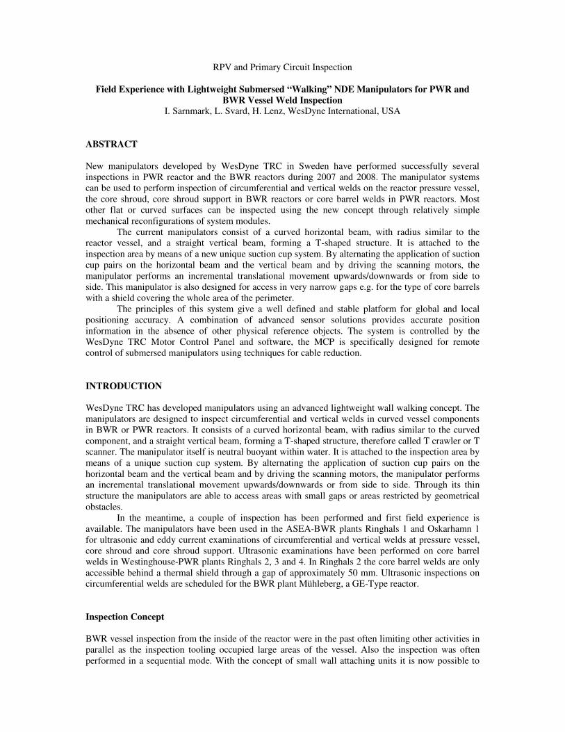
The inspections in 2007 were the biggest in-vessel inspection scope ever performed in Sweden
within a short time frame. The task was done simultaneously in one vessel with two identical T-robots
in parallel with a third simultaneous inspection using the ROV nozzle inspection robot Goldfish. With
the thin and flat design of the T-crawlers and the autonomous function with no need for supporting
rails and/or rods are the reactor and core region free for parallel activities. Figure 1 shows all three
manipulators during parallel inspection.
Compared to the previously used central mast tooling the introduction of the new inspection
concept resulted in a significantly reduced time (3x) compared to a sequential approach, a reduced set-
up and tear down time due to the reduced weight and the obsolesce for need of a polar crane.
Figure 1 - T-Scanners and Goldfish manipulator in parallel operation
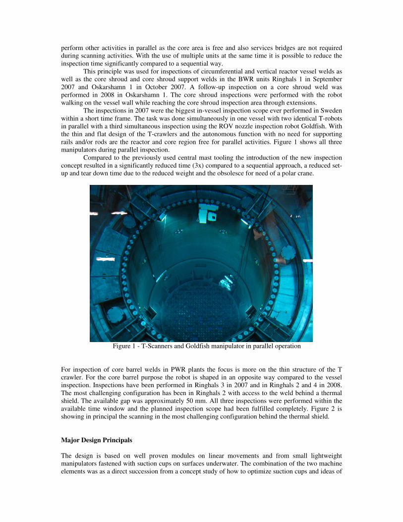
For inspection of core barrel welds in PWR plants the focus is more on the thin structure of the T
crawler. For the core barrel purpose the robot is shaped in an opposite way compared to the vessel
inspection. Inspections have been performed in Ringhals 3 in 2007 and in Ringhals 2 and 4 in 2008.
The most challenging configuration has been in Ringhals 2 with access to the weld behind a thermal
shield. The available gap was approximately 50 mm. All three inspections were performed within the
available time window and the planned inspection scope had been fulfilled completely. Figure 2 is
showing in principal the scanning in the most challenging configuration behind the thermal shield.
Major Design Principals
The design is based on well proven modules on linear movements and from small lightweight
manipulators fastened with suction cups on surfaces underwater. The combination of the two machine
elements was as a direct succession from a concept study of how to optimize suction cups and ideas of
a small multipurpose manipulator. When a customer demand on performing an inspection of a core
barrel was received, an ideal basis to develop the future platform for internals and vessel examinations
was present.
Figure 2 - T-Scanner configuration for core barrel inspection
The concept was evaluated and discussed with our customer and ended up in a proposal of a system
for not only the PWR core barrel but also for inspection of the complete reactor vessel, core shroud
and core shroud support for a BWR. The new manipulator systems are also suitable for quick single
NDE jobs such as sizing of an already known defect. Concepts on very advanced walking robots with
7-axis robot modules for a multipurpose use have been presented as well as different solutions on
small lightweight manipulators.
In common for many of these designs are the principle of controlling one direction of the scan
with magnetic wheels, and a perpendicular scan direction. This concept is refined in some
manipulators for underwater use with thrusters to create the force to push the manipulator against the
surface others use a rotating disc to create the attraction force. The manipulators have advanced
positioning systems to keep track of the position and changes of position and are also often neutral
buoyant in water to reduce the needed attraction force to the vessel wall.
The local and global position accuracy is depending on the surface structure, the position
systems and reference elements on the inspected object. The WesDyne TRC concept has the principle
of attaching a very simple 2-axis system, a X/Y scanner, to a fix position with a local positioning
that’s only depending on the very precise manipulator horizontal and vertical unit accuracy. A high
precision positioning system is used for determination of the global position just like other concepts.
The global position for the next step is a direct subsequent from a previous scan pattern or as a result
of a new reference object. The very firm fix position of the X/Y scanner permits our manipulators to
carry a relatively large payload of NDE probes. Repositioning is performed with the probes lifted from
the surface and therefore the probes have no influence on the position accuracy through friction forces.
For this concept of manipulators most NDE techniques can be applied. The focus for the first use with
the systems is UT for detection and sizing simultaneously combined with ET and TOFDT. For the
future on vessel wall is besides conventional UT also Phased array and VT discussed. Also moulding
technique would be possible to use on these rigid manipulators.
The positioning within a single X/Y scan area has a high precision and is only depending of the
manipulator internal accuracy, which is within millimeters for this system. The challenge is the global
positioning, which always is dependent on the environment.
WesDyne TRC experiences with our earlier designs, manipulators guided on a rail on the
vessel flange and with very long vertical masts, shows that this type of system will have an easy and
understandable polar coordinate system. The global coordinates for older systems are well defined but
not necessarily so precise since the position and dimensional errors are based on a long chain of
measures, all the way from the flange through the manipulator to the probes, this will certainly also
inflict the local measuring accuracy.
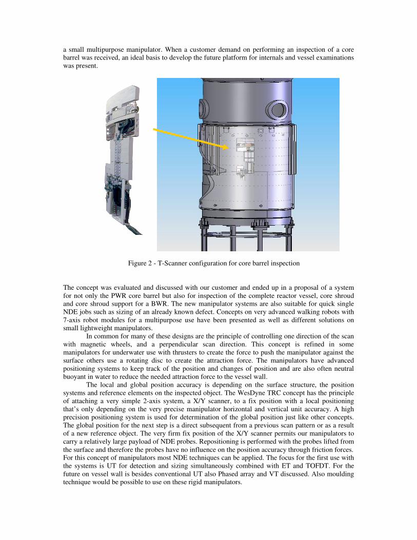
The global position for our new system is accomplished through several different measures.
The basic idea for the system is to use well known objects in the reactor it self. These objects will be
defined in global coordinates and then the manipulator is positioned close to the objects for detection
and position determination by immersion probes placed on the manipulator. By moving the immersion
probe horizontally above or below a reference object the circumferential position is determined quite
accurately, see figure 3. For an accurate vertical positioning a system with high precision pressure
gauges is used. One of the gauges is placed on a fixed vertical position as a reference. With the
reference gauge and the pressure gauge on the manipulator instantly temperature compensated and
calibrated relatively each other we can reach a very accurate vertical position.
Operation and Control
The manipulator control is operated through the WesDyne TRC standard Motion Control panel, MCP.
With this advanced multi-axis control system the manipulator can walk in manual or in automatic
mode. If a new grip with the suction cups is needed to reach the position this maneuver is performed
without the operator’s intervention. The operator just defines the desired coordinates and the
manipulator starts the translating movements. In every step automatically misalignment is
compensated and every new grip with the suction cups is monitored by vacuum gauges to secure a
firm grip for the next step. The new global position is calculated and presented to the operator
automatically.
Figure 3 - Principle of circumferential positioning with use of immersion probes
The suction cups with their individual ejector pump are integrated in four units and are propelled by
high pressure water from a plunger pump. This unique design of suction cup/pump also has the benefit
of keeping the highly contaminated water down at the object without transporting the radioactive
particles up to the surface and close to the operator. The high pressure water also supplies the water to
the jet spray nozzles which allow each individual suction cup to attach to the object by it self and also
makes it possible to use the manipulator as a ROV. The compact design of the components have been
vital for the extremely flat structure and the individual quick responding suction cup/water jet to
achieve effective walking performances.
Field Experiences
The good performance of the T scanners during six inspection campaigns since 2007 has proven the
basic design concept. Since the first inspection it was not necessary to improve or redesign major
elements. All inspections have been performed in or well below the available outage window.
Especially the most challenging inspection behind the thermal shield of a core barrel demonstrated the
capability of the tooling to walk behind small gaps. Also rough surface conditions didn’t pose a
problem for wall contact and positioning accuracy.
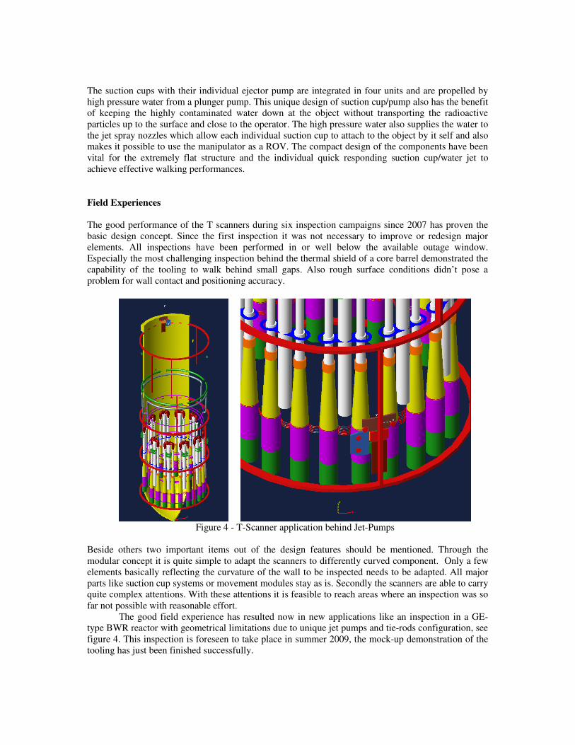
Figure 4 - T-Scanner application behind Jet-Pumps
Beside others two important items out of the design features should be mentioned. Through the
modular concept it is quite simple to adapt the scanners to differently curved component. Only a few
elements basically reflecting the curvature of the wall to be inspected needs to be adapted. All major
parts like suction cup systems or movement modules stay as is. Secondly the scanners are able to carry
quite complex attentions. With these attentions it is feasible to reach areas where an inspection was so
far not possible with reasonable effort.
The good field experience has resulted now in new applications like an inspection in a GE-
type BWR reactor with geometrical limitations due to unique jet pumps and tie-rods configuration, see
figure 4. This inspection is foreseen to take place in summer 2009, the mock-up demonstration of the
tooling has just been finished successfully.