Embed Size (px)
Citation preview

IX5000 Field-Replaceable Units and Country- and Region-Specific Power Connectors
Created: December 10, 2014Revised: June 2, 2017
This chapter describes the procedures you take to replace the field-replaceable units (FRUs) for the Cisco TelePresence System IX5000 and includes the following sections:
• Finding the System Serial Number, page 2
• List of Field-Replaceable Units, page 3
• Replacing the Camera—Part Number CTS-5K-CAM-CLSTR=, page 14
• Replacing a Display—Part Number CTS-5K-70-G1=, page 18
• Replacing a Codec—Part Number CTS-5K-ENCODER= or CTS-5K-HOSTCPU=, page 36
• Replacing a Microphone (Mic) Bar—Part Number CTS-5K-MIC=, page 40
Cisco Systems, Inc.www.cisco.com

Finding the System Serial Number
Finding the System Serial NumberYou might need the serial number of your IX5000 to order FRUs. The serial number is located on the pillar of the lower left display frame, underneath the compliance label. It is in the arrowed area shown in white in Figure 1.
Figure 1 Serial Number Label Location
2IX5000 Field-Replaceable Units and Country- and Region-Specific Power Connectors

List of Field-Replaceable Units
Pull away the lower fascia to see it as shown in Figure 2.
Figure 2 Compliance Label and Serial Number Location
List of Field-Replaceable UnitsTable 1 provides you with a list of the FRUs for the Cisco TelePresence System IX5000.
Table 1 List of Field-Replaceable Units
FRU Name Description Diagram Reference
CAB-DV10-4M= 4 meter flat grey Ethernet cable for Touch 10
CTS-5K-70-G1= 70-inch Display
CTS-5K-AMP-PWR= Subwoofer amplifier power supply
CTS-5K-AMP-SUBWFR= Subwoofer amplifier
3IX5000 Field-Replaceable Units and Country- and Region-Specific Power Connectors

List of Field-Replaceable Units
CTS-5K-BZL-KIT= Vertical bezel extrusions and horizontal display trim
CTS-5K-CAM-CLSTR= Camera
CTS-5K-CAM-HS= Camera lens hood (camera cover)
CTS-5K-CAM-TOOL= Camera targets
CTS-5K-CBL-70DSP= CTS-IX5000 Cable kit for main the main displays1 H1, H2, H3, D20, D19, D23
CTS-5K-CBL-CODEC= CTS-IX5000 Cable kit for the Encoder/Decoder codec1
USB1, iPass, D24
CTS-5K-CBL-CUP= Presentation cable cup
CTS-5K-CBL-EP= CTS-IX5000 Cable Kit for speaker, lights and camera1 L1, L2, L3, L4, L5, L6, DP1
CTS-5K-CBL-HOST= CTS-IX5000 Cable kit for the Host CPU1 DP2, DP3, AX1, D22
CTS-5K-CBL-R1-AC= CTS-IX5000 Cable kit, front row AC cables1
CTS-5K-CBL-R1-LAP= CTS-IX5000 Cable kit, front row table Ethernet Lapconns1
CX1, C1-C6
CTS-5K-CBL-R1-MIC= CTS-IX5000 Cable kit, front row table audio1 A1-A6
CTS-5K-CBL-R1-SW= CTS-IX5000 Cable kit, front row table switch1 EX1
CTS-5K-CBL-R2-AC= CTS-IX5000 Cable kit, back row AC cables1
CTS-5K-CBL-R2-LAP= CTS-IX5000 Cable kit, back row table Ethernet Lapconns1
CX2, C7-C18
CTS-5K-CBL-R2-MIC= CTS-IX5000 Cable kit, back row table audio1 AX2, AX3, A7-A18
CTS-5K-CBL-R2-SW= CTS-IX5000 Cable kit, back row switches1 EX2, EX3
CTS-5K-CBL-RTR= Presentation cable with three-headed connector—includes cable and cable retractor
L7, L8
CTS-5K-CBL-RUN= Cable runner assembly (includes cable runner and cable runner cover)
CTS-5K-CBL-RUN-A= 42-inch data display bracket and cable runner kit
CTS-5K-CBL-SUBW= CTS-IX5000 Cable Kit for the Subwoofer1 USB2, A28, A29, D21
CTS-5K-DISP42= 42-inch data display
CTS-5K-ENCODER-CH= Encoder/Decoder codec—China only
CTS-5K-ENCODER++= CTS-IX5000 TAA Encoder / Decoder for US only
CTS-5K-ENCODER= Encoder/Decoder codec—all countries except China
CTS-5K-EP-HW-KIT= Endpoint hardware kit
CTS-5K-EP-PDU= Endpoint Power Distribution Unit (PDU)
CTS-5K-FAB-PNL-B= Outer leg panels
CTS-5K-FAB-PNL-EP= Endpoint PET plastic panels (includes left, right, center top, and center bottom PET panels)
CTS-5K-FAB-PNL-F= Front row outer leg panels
CTS-5K-FASCIA-KIT= Top and bottom fascia
CTS-5K-HOSTCPU-CH= Host CPU codec—China only
Table 1 List of Field-Replaceable Units (continued)
FRU Name Description Diagram Reference
4IX5000 Field-Replaceable Units and Country- and Region-Specific Power Connectors

List of Field-Replaceable Units
CTS-5K-HOSTCPU= Host CPU codec—all countries except China
CTS-5K-HW-BR-KIT= 2nd row table hardware kit
CTS-5K-HW-FR-KIT= Front row table hardware kit
CTS-5K-LED-KIT= Light panel kit (includes left, center, and right light panels)
CTS-5K-LEGS-BACK= 2nd row table legs
CTS-5K-LEGS-FRNT= Front row table legs
CTS-5K-LPS-MECH= Mechnical Kit for optional Ethernet switch (located in endpoint structure)
CTS-5K-MECH-FRAME= Endpoint display frames (includes upper and lower display frames)
CTS-5K-MIC-TA= Turnaround microphone (for 2nd row table)
CTS-5K-MIC= Microphone (mic) bar
CTS-5K-MTL-BR-KIT= 2nd row cable management assemblies (the sheet metal sections that go between the table legs)
CTS-5K-MTL-FR-KIT= CTS-IX5000 front row table cable management assembly
CTS-5K-MUTE-BTN= Mute button IX5000
Seismic bracket kit
CTS-5K-SHTML-MISC= Miscellaneous sheetmetal kit
CTS-5K-SPKR= Speaker
CTS-5K-SUBWOOFER= Subwoofer
CTS-5K-TBL-H-18S= Front and second row tabletop set, hickory
CTS-5K-TBL-H-6S= Front row tabletop set, hickory
CTS-5K-TBL-M-18S= Front and second row tabletop set, maple
CTS-5K-TBL-M-6S= Front row tabletop set, maple
CTS-5K-TBL-PDU= Table PDU
CTS-5K-TBL-W-18S= Front and second row tabletop set, walnut
CTS-5K-TBL-W-6S= Front row tabletop set, walnut
CTS-5K-TDM= TDM for microphone (mic) bars
CTS-5K-THERM-PNLS= Thermoformed panels (includes center, right, and left upper cabinets, and lower left and right cabinets)
CTS-5K-WHTBD-TOOL= Whiteboard alignment targets
CTS-CTRL-DV10= Touch 10 device
WS-C2960C-8PC-L Replacement switch for the Touch 10 switches in the table (Catalyst 3560C Switch 8 FE PoE, 2 x Dual Uplink, IP Base)
Table 1 List of Field-Replaceable Units (continued)
FRU Name Description Diagram Reference
5IX5000 Field-Replaceable Units and Country- and Region-Specific Power Connectors

Region-and Country-Specific Power and Table Leg Connectors
Region-and Country-Specific Power and Table Leg Connectors
Table 2 provides you with a list of the region- and country-specific power cables that plug the IX5000 system.
1. For a complete list of the contents of each cable kit, see the “IX5000 and IX5200 Parts List Sorted by Carton” document at http://www.cisco.com/c/en/us/td/docs/telepresence/ix5000/carton_contents/ix5000_carton_and_parts_list.html and search for the cable kit FRU name, removing the equal sign. For example, for a complete list of the cables in the Encoder/Decoder cable kit, open the Parts List Sorted by Carton document and search for CTS-5K-CBL-CODEC.
Table 2 Region- and Country-Specific Power Cables and Table Leg Laptop Power Connectivity
Power Cord ID Description
PWR-CORD10-AP= TelePresence 10 Power Cord - Asia Pacific
PWR-CORD10-AR= TelePresence 10 Power Cord - Argentina
PWR-CORD10-AU= TelePresence 10 Power Cord - Australia
6IX5000 Field-Replaceable Units and Country- and Region-Specific Power Connectors

Region-and Country-Specific Power and Table Leg Connectors
PWR-CORD10-BZ= TelePresence 10 Power Cord - Brazil
PWR-CORD10-CE= TelePresence 10 Power Cord - Central Europe
PWR-CORD10-CN= TelePresence 10 Power Cord - China
PWR-CORD10-ID= TelePresence 10 Power Cord - India, UAE, South Africa
Table 2 Region- and Country-Specific Power Cables and Table Leg Laptop Power Connectivity
Power Cord ID Description
7IX5000 Field-Replaceable Units and Country- and Region-Specific Power Connectors

Region-and Country-Specific Power and Table Leg Connectors
PWR-CORD10-ISR= TelePresence 10 Power Cord - Israel
PWR-CORD10-ITA= TelePresence 10 Power Cord - Italy
PWR-CORD10-JP= TelePresence 10 Power Cord - Japan
PWR-CORD-NA= TelePresence 10 Power Cord - North America
Table 2 Region- and Country-Specific Power Cables and Table Leg Laptop Power Connectivity
Power Cord ID Description
8IX5000 Field-Replaceable Units and Country- and Region-Specific Power Connectors

Region-and Country-Specific Power and Table Leg Connectors
PWR-CORD10-SWI= TelePresence 10 Power Cord - Switzerland
PWR-CORD10-UK= TelePresence 10 Power Cord - United Kingdom
CTS-LAPCONN-AP= TelePresence Laptop Connectivity - Asia Pacific
Table 2 Region- and Country-Specific Power Cables and Table Leg Laptop Power Connectivity
Power Cord ID Description
9IX5000 Field-Replaceable Units and Country- and Region-Specific Power Connectors

Region-and Country-Specific Power and Table Leg Connectors
CTS-LAPCONN-AR= TelePresence Laptop Connectivity - Argentina
CTS-LAPCONN-AU= TelePresence Laptop Connectivity - Australia
CTS-LAPCONN-BZ= TelePresence Laptop Connectivity - Brazil
Table 2 Region- and Country-Specific Power Cables and Table Leg Laptop Power Connectivity
Power Cord ID Description
10IX5000 Field-Replaceable Units and Country- and Region-Specific Power Connectors

Region-and Country-Specific Power and Table Leg Connectors
CTS-LAPCONN-CE= TelePresence Laptop Connectivity - Central Europe
CTS-LAPCONN-CN= TelePresence Laptop Connectivity - China
CTS-LAPCONN-ID= TelePresence Laptop Connectivity - India, UAE
Table 2 Region- and Country-Specific Power Cables and Table Leg Laptop Power Connectivity
Power Cord ID Description
11IX5000 Field-Replaceable Units and Country- and Region-Specific Power Connectors

Region-and Country-Specific Power and Table Leg Connectors
CTS-LAPCONN-ISR= TelePresence Laptop Connectivity - Israel
CTS-LAPCONN-ITA= TelePresence Laptop Connectivity - Italy
CTS-LAPCONN-JP= TelePresence Laptop Connectivity - Japan
Table 2 Region- and Country-Specific Power Cables and Table Leg Laptop Power Connectivity
Power Cord ID Description
12IX5000 Field-Replaceable Units and Country- and Region-Specific Power Connectors

Region-and Country-Specific Power and Table Leg Connectors
CTS-LAPCONN-NA= TelePresence Laptop Connectivity - North America
CTS-LAPCONN-SA= TelePresence Laptop Connectivity - South Africa
CTS-LAPCONN-SWI= TelePresence Laptop Connectivity - Switzerland
CTS-LAPCONN-UK= TelePresence Laptop Connectivity - United Kingdom
Table 2 Region- and Country-Specific Power Cables and Table Leg Laptop Power Connectivity
Power Cord ID Description
13IX5000 Field-Replaceable Units and Country- and Region-Specific Power Connectors
Replacing the Camera—Part Number CTS-5K-CAM-CLSTR=
Replacing the Camera—Part Number CTS-5K-CAM-CLSTR=
Required Tools
• #2 and #3 Phillips driver
• Gloves (to prevent discoloration of the fascias)
Procedure
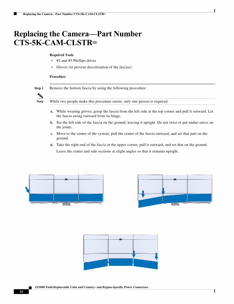
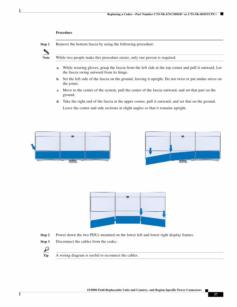
Step 1 Remove the bottom fascia by using the following procedure:
Note While two people make this procedure easier, only one person is required.
a. While wearing gloves, grasp the fascia from the left side at the top corner and pull it outward. Let the fascia swing outward from its hinge.
b. Set the left side of the fascia on the ground, leaving it upright. Do not twist or put undue stress on the joints.
c. Move to the center of the system, pull the center of the fascia outward, and set that part on the ground.
d. Take the right end of the fascia at the upper corner, pull it outward, and set that on the ground.
Leave the center and side sections at slight angles so that it remains upright.
14IX5000 Field-Replaceable Units and Country- and Region-Specific Power Connectors

Replacing the Camera—Part Number CTS-5K-CAM-CLSTR=
Step 2 Power down the two PDUs mounted on the lower left and lower right display frames.
Step 3 Remove the camera lens hood (camera cover) by pulling it away from the endpoint structure. The cover attaches to the structure with magnets.
Step 4 While still wearing gloves, remove the upper fascia by grasping the left side of the fascia and pulling it out. Continue holding the left side while moving towards the center of the system. Gently fold and join the left side onto the center, making sure not to bend or crease the fascia (it should hold a U shape where it folds over - not a V shape). Move to the right of the system and continue to pull the fascia outward.
15IX5000 Field-Replaceable Units and Country- and Region-Specific Power Connectors

Replacing the Camera—Part Number CTS-5K-CAM-CLSTR=
Fold it over once more and join the center section with the right section. Continue removing the fascia until the entire fascia is removed from the system. Set the fascia on the ground and leave it in three U-shaped sections.
Step 5 Remove the center speaker cover using #2 and #3 Phillips screwdrivers.
16IX5000 Field-Replaceable Units and Country- and Region-Specific Power Connectors

Replacing the Camera—Part Number CTS-5K-CAM-CLSTR=
Caution Be careful not to jar the center light panel loose when you remove the speaker cover.
Step 6 Find the pigtail wire coming from the left side of the center light panel, and disconnect the connector at the end of the pigtail. Then, lift the center light panel upward and pull the lower part outward, and remove it from the endpoint structure.
17IX5000 Field-Replaceable Units and Country- and Region-Specific Power Connectors

Replacing a Display—Part Number CTS-5K-70-G1=
Step 7 Remove the camera by unscrewing the four captive screws that connect it to the endpoint structure.
Step 8 Install the new camera.
Step 9 Replace the center light panel and center speaker cover.
Step 10 Replace the upper facade and lens hood cover (camera cover).
Step 11 Power on the PDUs on the lower part of the endpoint structure.
Step 12 Log into the Cisco TelePresence Administrative UI and perform the camera alignment procedure.
Step 13 Replace the lower facade.
For detailed steps and additional illustrations, refer to the IX5000 installation guide and the first-time setup chapter.
Replacing a Display—Part Number CTS-5K-70-G1=Required Tools
#2 and #3 Phillips drivers.
18IX5000 Field-Replaceable Units and Country- and Region-Specific Power Connectors

Replacing a Display—Part Number CTS-5K-70-G1=
Replacing a Left or Right Display
Step 1 Remove the bottom fascia by using the following procedure:
Note While two people make this procedure easier, only one person is required.
a. While wearing gloves, grasp the fascia from the left side at the top corner and pull it outward. Let the fascia swing outward from its hinge.
b. Set the left side of the fascia on the ground, leaving it upright. Do not twist or put undue stress on the joints.
c. Move to the center of the system, pull the center of the fascia outward, and set that part on the ground.
d. Take the right end of the fascia at the upper corner, pull it outward, and set that on the ground.
Leave the center and side sections at slight angles so that it remains upright.
Step 2 Power down the two PDUs mounted on the lower left and lower right display frames.
19IX5000 Field-Replaceable Units and Country- and Region-Specific Power Connectors

Replacing a Display—Part Number CTS-5K-70-G1=
Step 3 Remove the camera lens hood (camera cover) by pulling it away from the endpoint structure. The cover attaches to the structure with magnets.
Step 4 While still wearing gloves, remove the upper fascia by grasping the left side of the fascia and pulling it out. Continue holding the left side while moving towards the center of the system. Gently fold and join the left side onto the center, making sure not to bend or crease the fascia (it should hold a U shape where it folds over - not a V shape). Move to the right of the system and continue to pull the fascia outward. Fold it over once more and join the center section with the right section. Continue removing the fascia until the entire fascia is removed from the system. Set the fascia on the ground and leave it in three U-shaped sections.
20IX5000 Field-Replaceable Units and Country- and Region-Specific Power Connectors

Replacing a Display—Part Number CTS-5K-70-G1=
Step 5 Remove the horizontal display trim from the underside of the panels.
21IX5000 Field-Replaceable Units and Country- and Region-Specific Power Connectors

Replacing a Display—Part Number CTS-5K-70-G1=
Step 6 While wearing gloves, remove the right or left PET panels, depending on which display requires replacement, by pulling them upward and outward.
Step 7 Remove the lower corner cabinet. Remove the right cabinet for the right display, remove the left cabinet for the left display. Four screws attach the cabinet to the lower display frame.
22IX5000 Field-Replaceable Units and Country- and Region-Specific Power Connectors

Replacing a Display—Part Number CTS-5K-70-G1=
Step 8 Remove the upper and cabinet (right for the right display, left for the left display).
Step 9 Remove the vertical bezel extrusions. Remove the two screws on the lower part of the extrusion, then rotate the extrusion upward from the bottom and lift it free of the endpoint structure.
23IX5000 Field-Replaceable Units and Country- and Region-Specific Power Connectors

Replacing a Display—Part Number CTS-5K-70-G1=
Step 10 Remove the right or left speaker cover. Remove the four captive screws, and two recessed screws.
Step 11 Disconnect the pigtail connector on the side of the light panel and remove the light panel above the display to be removed.
24IX5000 Field-Replaceable Units and Country- and Region-Specific Power Connectors

Replacing a Display—Part Number CTS-5K-70-G1=
Step 12 Remove the speakers that are above the display you want to replace (right speakers for right display, center speakers for center display, and left speakers for left display). There are four screws per speaker.
25IX5000 Field-Replaceable Units and Country- and Region-Specific Power Connectors

Replacing a Display—Part Number CTS-5K-70-G1=
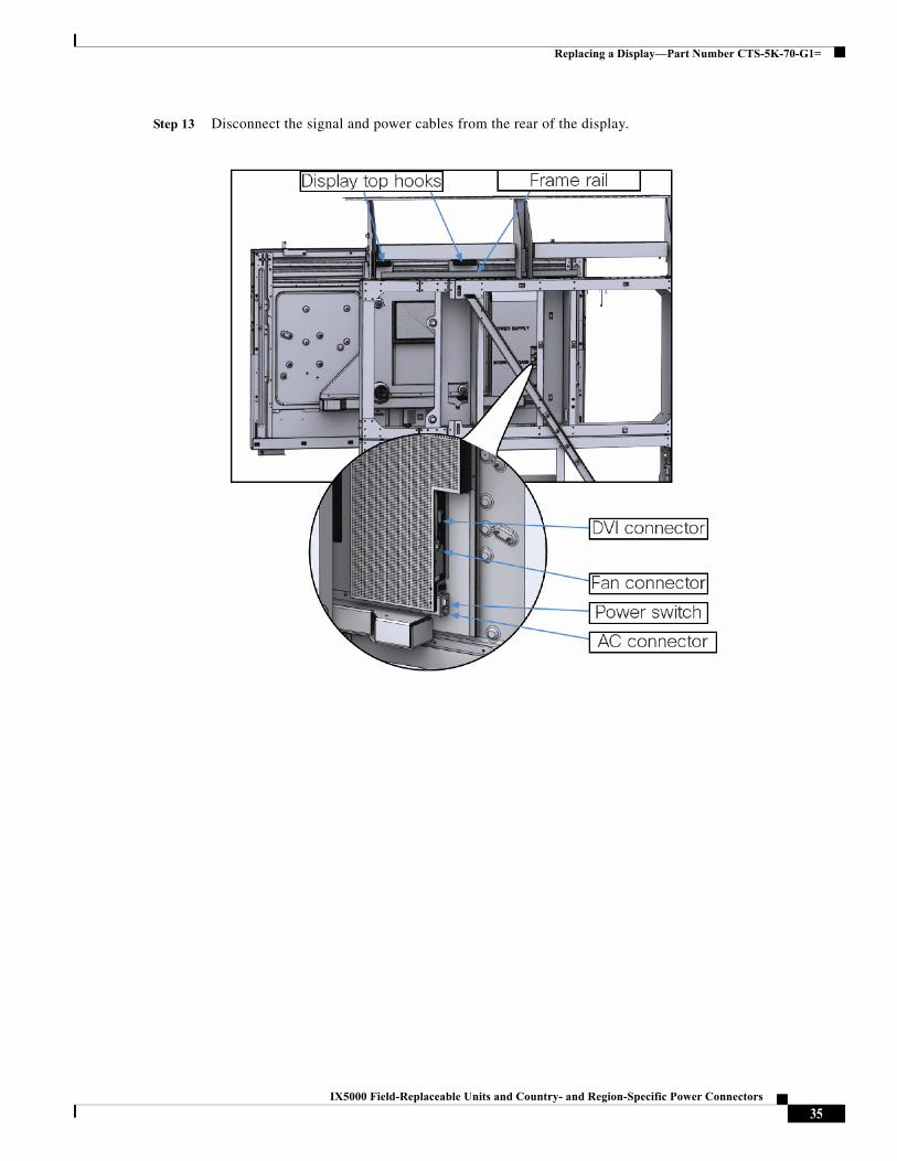
Step 13 Disconnect the signal and power cables from the rear of the display.
26IX5000 Field-Replaceable Units and Country- and Region-Specific Power Connectors

Replacing a Display—Part Number CTS-5K-70-G1=
Step 14 Using two people, remove the display so that it lifts clear of the display shelf and the spool goes through the cutout slot in the rear of the endpoint structure.
Step 15 Prepare the new display for installation by installing the leveler bracket and stud, washer, and spool. You can reuse the old bracket, or use the one that is included with the new display.
27IX5000 Field-Replaceable Units and Country- and Region-Specific Power Connectors

Replacing a Display—Part Number CTS-5K-70-G1=
Note the 1/18” distance between the spool and the display after installation. This measurement is important for ease of installation.
Step 16 Install the display and replace all other components in the reverse order that you removed them.
Step 17 Be sure to power on the PDUs before you re-install the bottom fascia.
Replacing a Center Display
Step 1 Remove the bottom fascia by using the following procedure:
Note While two people make this procedure easier, only one person is required.
a. While wearing gloves, grasp the fascia from the left side at the top corner and pull it outward. Let the fascia swing outward from its hinge.
b. Set the left side of the fascia on the ground, leaving it upright. Do not twist or put undue stress on the joints.
c. Move to the center of the system, pull the center of the fascia outward, and set that part on the ground.
d. Take the right end of the fascia at the upper corner, pull it outward, and set that on the ground.
Leave the center and side sections at slight angles so that it remains upright.
28IX5000 Field-Replaceable Units and Country- and Region-Specific Power Connectors

Replacing a Display—Part Number CTS-5K-70-G1=
Step 2 Power down the two PDUs mounted on the lower left and lower right display frames.
29IX5000 Field-Replaceable Units and Country- and Region-Specific Power Connectors

Replacing a Display—Part Number CTS-5K-70-G1=
Step 3 Remove the camera lens hood (camera cover) by pulling it away from the endpoint structure. The cover attaches to the structure with magnets.
Step 4 While still wearing gloves, remove the upper fascia by grasping the left side of the fascia and pulling it out. Continue holding the left side while moving towards the center of the system. Gently fold and join the left side onto the center, making sure not to bend or crease the fascia (it should hold a U shape where it folds over - not a V shape). Move to the right of the system and continue to pull the fascia outward. Fold it over once more and join the center section with the right section. Continue removing the fascia until the entire fascia is removed from the system. Set the fascia on the ground and leave it in three U-shaped sections.
30IX5000 Field-Replaceable Units and Country- and Region-Specific Power Connectors

Replacing a Display—Part Number CTS-5K-70-G1=
Step 5 Remove the horizontal display trim from the underside of the panels.
31IX5000 Field-Replaceable Units and Country- and Region-Specific Power Connectors

Replacing a Display—Part Number CTS-5K-70-G1=
Step 6 While wearing gloves, remove the top and bottom center PET panels by pulling them upward, then outward.
Step 7 Remove the center cabinet.
32IX5000 Field-Replaceable Units and Country- and Region-Specific Power Connectors

Replacing a Display—Part Number CTS-5K-70-G1=
Step 8 Remove the vertical bezel extrusions. Remove the two screws on the lower part of the extrusion, then rotate the extrusion upward from the bottom and lift it free of the endpoint structure.
Step 9 Remove the center speaker cover. Remove the four captive screws, and two recessed screws.
33IX5000 Field-Replaceable Units and Country- and Region-Specific Power Connectors

Replacing a Display—Part Number CTS-5K-70-G1=
Step 10 Disconnect the pigtail connector on the side of the light panel and remove the center light panel.
Step 11 Remove the camera by unscrewing the four captive screws that connect it to the endpoint structure.
Step 12 Remove the center speakers (four screws per speaker).
34IX5000 Field-Replaceable Units and Country- and Region-Specific Power Connectors
Replacing a Display—Part Number CTS-5K-70-G1=
Step 13 Disconnect the signal and power cables from the rear of the display.
35IX5000 Field-Replaceable Units and Country- and Region-Specific Power Connectors

Replacing a Codec—Part Number CTS-5K-ENCODER= or CTS-5K-HOSTCPU=
Step 14 Using two people, remove the display so that it lifts clear of the display shelf.
Step 15 Install the display and replace all other components in the reverse order that you removed them. Note that this display goes on without the add-ons used for the left and right displays (spool and bracket).
Step 16 Be sure to power on the PDUs before you re-install the bottom fascia.
Replacing a Codec—Part Number CTS-5K-ENCODER= or CTS-5K-HOSTCPU=
IMPORTANT NOTE
You must disconnect the power to the switch and the table, and disconnect the Touch 10 devices, after you replace the codec. For more information, refer to the “Preventing Touch 10 Configuration Issues” section of the IX5000 and IX5200 First-Time Setup document.
Required Tools
• #2 and #3 Phillips Driver
• Wiring diagram
36IX5000 Field-Replaceable Units and Country- and Region-Specific Power Connectors
Replacing a Codec—Part Number CTS-5K-ENCODER= or CTS-5K-HOSTCPU=
Procedure
Step 1 Remove the bottom fascia by using the following procedure:
Note While two people make this procedure easier, only one person is required.
a. While wearing gloves, grasp the fascia from the left side at the top corner and pull it outward. Let the fascia swing outward from its hinge.
b. Set the left side of the fascia on the ground, leaving it upright. Do not twist or put undue stress on the joints.
c. Move to the center of the system, pull the center of the fascia outward, and set that part on the ground.
d. Take the right end of the fascia at the upper corner, pull it outward, and set that on the ground.
Leave the center and side sections at slight angles so that it remains upright.
Step 2 Power down the two PDUs mounted on the lower left and lower right display frames.
Step 3 Disconnect the cables from the codec.
Tip A wiring diagram is useful to reconnect the cables.
37IX5000 Field-Replaceable Units and Country- and Region-Specific Power Connectors

Replacing a Codec—Part Number CTS-5K-ENCODER= or CTS-5K-HOSTCPU=
Step 4 Unfasten the six screws that hold the codec to the cable and pull the codec upward and outward from the frame using a #3 Phillips driver. The procedure to remove the encoder/decoder codec, or the Host CPU codec, is the same.
Figure 3 Removing the Host CPU Codec from the Frame
38IX5000 Field-Replaceable Units and Country- and Region-Specific Power Connectors

Replacing a Codec—Part Number CTS-5K-ENCODER= or CTS-5K-HOSTCPU=
Figure 4 Removing the Encoder/Decoder Codec from the Frame
Step 5 Remove the bracket from the codec using a #2 Phillips driver.
Figure 5 Removing the Brackets from the Host CPU Codec
39IX5000 Field-Replaceable Units and Country- and Region-Specific Power Connectors

Replacing a Microphone (Mic) Bar—Part Number CTS-5K-MIC=
Figure 6 Removing the Brackets from the Encoder/Decoder Codec
Step 6 Attach the brackets to the new codec.
Step 7 Insert the codec into the endpoint structure.
Step 8 Reconnect the cables.
Step 9 Disconnect the power to the switch and the table, and disconnect the Touch 10 devices. For more information, refer to the “Preventing Touch 10 Configuration Issues” section of the IX5000 and IX5200 First-Time Setup document.
Step 10 Power on the PDUs.
Step 11 Attach the bottom fascia.
Step 12 Perform first-time setup of the system. For more information. refer to the IX5000 and IX5200 First-Time Setup document.
Replacing a Microphone (Mic) Bar—Part Number CTS-5K-MIC=
Required Tools
#2 Phillips screwdriver
40IX5000 Field-Replaceable Units and Country- and Region-Specific Power Connectors

Replacing a Microphone (Mic) Bar—Part Number CTS-5K-MIC=
Procedure
Step 1 Remove the mute button covers. This procedure is the same for either the first or second row.
Step 2 (Center first row microphone and all 2nd row microphones only) Remove the front panel from the table section from which the mic bar will be removed.
Step 3 From underneath the table section, remove the screws that connect the mic bar to the table (six per mic bar) using a #2 Phillips driver.
Note If a cable for the Touch 10 goes through the center of the mic bar, unscrew the screw that secures the mic bar cap to the mic bar, disconnect the Ethernet cable from the Touch 10 device, and thread the Ethernet cable out from the center of the mic bar,
41IX5000 Field-Replaceable Units and Country- and Region-Specific Power Connectors

Replacing a Microphone (Mic) Bar—Part Number CTS-5K-MIC=
Step 4 Remove the mini-DisplayPort and mute button cables from the mic bar, and remove the mic bar from the table.
Step 5 Place the mic bar on the table, and connect the mute button cable and mini-DisplayPort cables
Step 6 Make sure that the cables underneath the table are routed correctly.
Step 7 Set the mic bar down in its recess in the table and reconnect using the six screws you removed earlier.
Step 8 Replace the front panel and mute button covers in the reverse order that you removed them.
42IX5000 Field-Replaceable Units and Country- and Region-Specific Power Connectors

Replacing a Microphone (Mic) Bar—Part Number CTS-5K-MIC=
43IX5000 Field-Replaceable Units and Country- and Region-Specific Power Connectors

Replacing a Microphone (Mic) Bar—Part Number CTS-5K-MIC=
44IX5000 Field-Replaceable Units and Country- and Region-Specific Power Connectors