Embed Size (px)
Citation preview

Field Strength and Power EstimatorApplication Note
Determining the field strength from transmitted power is not an easy job. Various, quite complicated formulas have to be evaluatedcorrectly. This application note explains how to calculate electric and magnetic field strength, and power flux density. A programassociated with this application note helps with the calculation and converts Watts to mW and dBm, V/m to µV/m and dBµV/m aswell as A/m to µA/m and dBµA/m. Additional applications are calculation of propagation loss or antenna factor. Smartphone ver-sions of the application software are also available.
Note:
Please find the most up-to-date document on our homepage http://www.rohde-schwarz.com/appnote/1MA85.
This document is complemented by software. The software may be updated even if the version of the docu-ment remains unchanged
Appli
catio
n Note
Field Strength and Power Estimator ─ 1MA85_6e
F. S
chütz
e, A.
Wint
er, L
. Yor
dano
v
Contents
2Application Note Field Strength and Power Estimator ─ 1MA85_6e
Contents1 Introduction............................................................................................ 3
2 Software Features and Formulas......................................................... 42.1 Power Flux Density....................................................................................................... 4
2.2 Antenna Characteristics...............................................................................................5
2.3 Receiving Signals and Measuring Power Flux Density.............................................6
2.4 Receiving Signals and Measuring Electric Field Strength........................................7
2.5 Receiving Signals and Measuring Magnetic Field Strength..................................... 8
3 Installing and Starting Field Strength and Power Estimator........... 103.1 Mac OSX.......................................................................................................................10
3.2 Windows...................................................................................................................... 11
4 Operating the Program........................................................................124.1 Entering numerical values......................................................................................... 12
4.2 Starting Calculation.................................................................................................... 13
4.3 Main / About Menu...................................................................................................... 14
4.4 Save and Recall Settings............................................................................................15
4.5 Help.............................................................................................................................. 15
5 Some Examples....................................................................................175.1 Determining the Propagation Attenuation between 2 Antennas............................ 17
5.2 Determining the Transmit Power for a GPS Simulation.......................................... 17
5.3 Using EIRP...................................................................................................................18
5.4 Calculating Antenna Factor from Antenna Gain...................................................... 18
6 Smartphone App Versions..................................................................20
7 Rohde & Schwarz.................................................................................21
Introduction
3Application Note Field Strength and Power Estimator ─ 1MA85_6e
1 IntroductionDetermining the field strength from transmitted power and frequency is not an easy job.This application note explains how to calculate electric and magnetic field strength, andpower flux density.
The program Field Strength and Power Estimator available with this application notehelps with the calculation and converts mW to dBm, V/m to µV/m and dBµV/m as wellas A/m to µA/m and dBµA/m.
● An introduction of the program features and the calculation formulas is presented.● Information about installing and operating the program are given.● Some examples show additional applications of the program.
Software Features and Formulas
4Application Note Field Strength and Power Estimator ─ 1MA85_6e
2 Software Features and FormulasThe program Field Strength and Power Estimator calculates power flux density, electricand magnetic field strength from the transmitted power, associated frequency and gainof the transmitting antenna.
Additionally the input power into a receiver with 50Ω(Ohm) input impedance is calcula-ted from the gain of the receiving antenna.
The program automatically converts power flux density into electric and magnetic fieldstrength.
Depending on the transmitted frequency, various parameters influence the receivedpower and field strength, such as Non-line-of-sight propagation, changes in polariza-tion, reflections, and multi path propagation affect the true values. Additionally antennaVSWR and cable losses have to be considered.
The program Field strength and Power Estimator does not consider these impairments.It assumes conditions, that are close to the best possible theoretical values. This iswhy we say the program is an Estimator, not a Calculator.
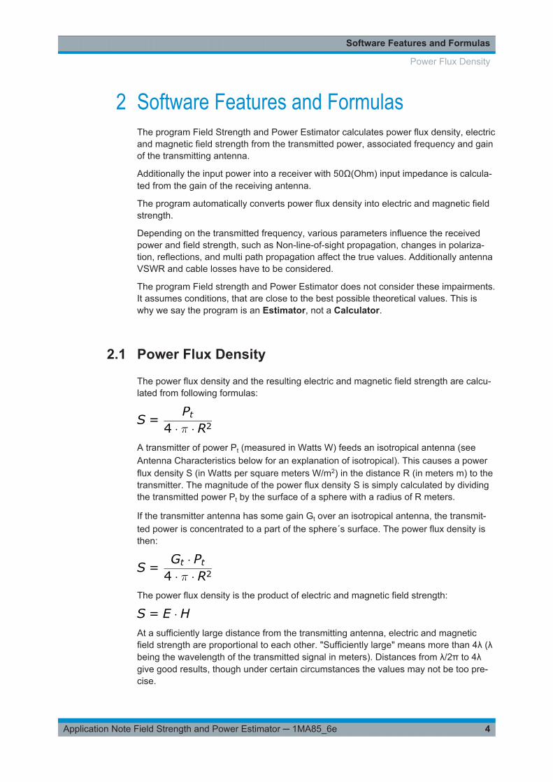
2.1 Power Flux Density
The power flux density and the resulting electric and magnetic field strength are calcu-lated from following formulas:
A transmitter of power Pt (measured in Watts W) feeds an isotropical antenna (seeAntenna Characteristics below for an explanation of isotropical). This causes a powerflux density S (in Watts per square meters W/m2) in the distance R (in meters m) to thetransmitter. The magnitude of the power flux density S is simply calculated by dividingthe transmitted power Pt by the surface of a sphere with a radius of R meters.
If the transmitter antenna has some gain Gt over an isotropical antenna, the transmit-ted power is concentrated to a part of the sphere´s surface. The power flux density isthen:
The power flux density is the product of electric and magnetic field strength:
At a sufficiently large distance from the transmitting antenna, electric and magneticfield strength are proportional to each other. "Sufficiently large" means more than 4λ (λbeing the wavelength of the transmitted signal in meters). Distances from λ/2π to 4λgive good results, though under certain circumstances the values may not be too pre-cise.
Power Flux Density
Software Features and Formulas
5Application Note Field Strength and Power Estimator ─ 1MA85_6e
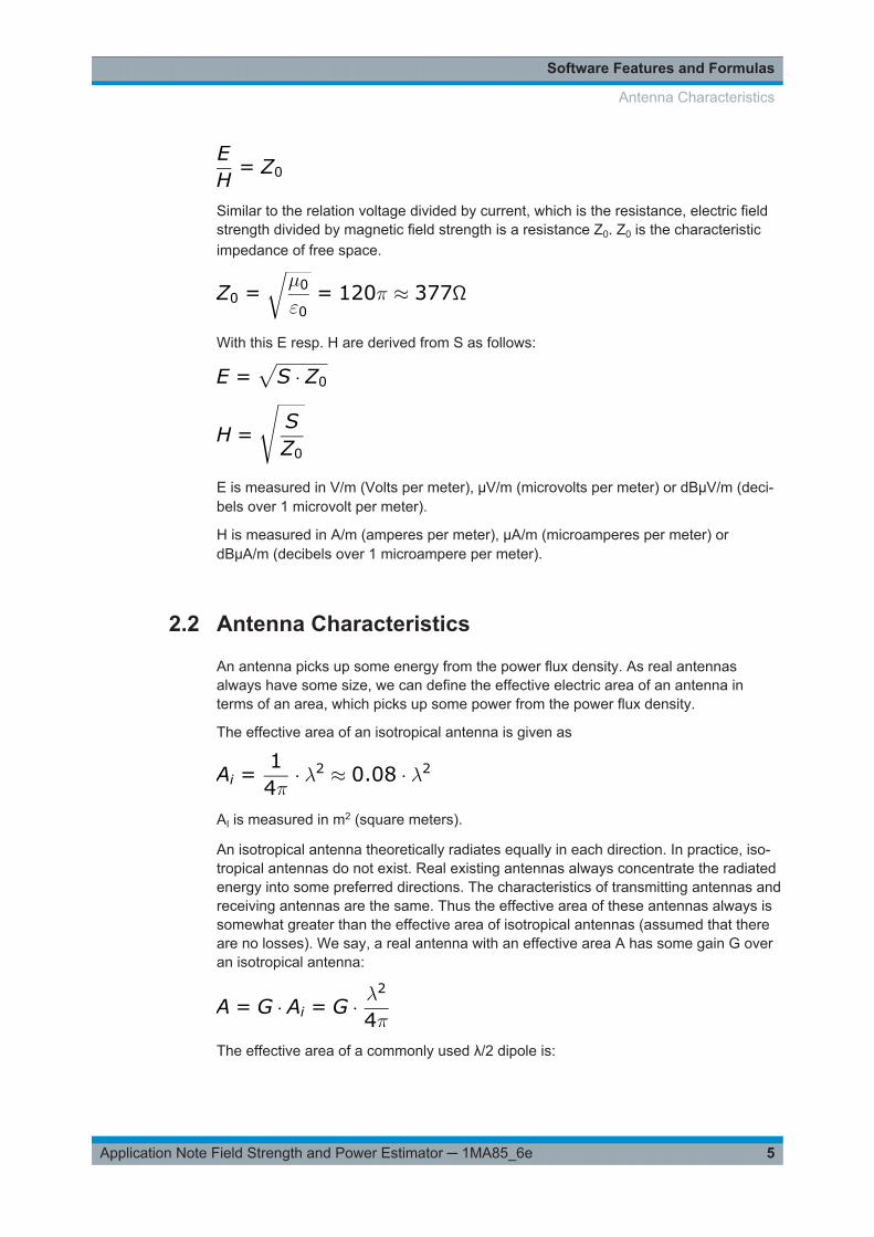
Similar to the relation voltage divided by current, which is the resistance, electric fieldstrength divided by magnetic field strength is a resistance Z0. Z0 is the characteristicimpedance of free space.
With this E resp. H are derived from S as follows:
E is measured in V/m (Volts per meter), µV/m (microvolts per meter) or dBµV/m (deci-bels over 1 microvolt per meter).
H is measured in A/m (amperes per meter), µA/m (microamperes per meter) ordBµA/m (decibels over 1 microampere per meter).
2.2 Antenna Characteristics
An antenna picks up some energy from the power flux density. As real antennasalways have some size, we can define the effective electric area of an antenna interms of an area, which picks up some power from the power flux density.
The effective area of an isotropical antenna is given as
AI is measured in m2 (square meters).
An isotropical antenna theoretically radiates equally in each direction. In practice, iso-tropical antennas do not exist. Real existing antennas always concentrate the radiatedenergy into some preferred directions. The characteristics of transmitting antennas andreceiving antennas are the same. Thus the effective area of these antennas always issomewhat greater than the effective area of isotropical antennas (assumed that thereare no losses). We say, a real antenna with an effective area A has some gain G overan isotropical antenna:
The effective area of a commonly used λ/2 dipole is:
Antenna Characteristics
Software Features and Formulas
6Application Note Field Strength and Power Estimator ─ 1MA85_6e
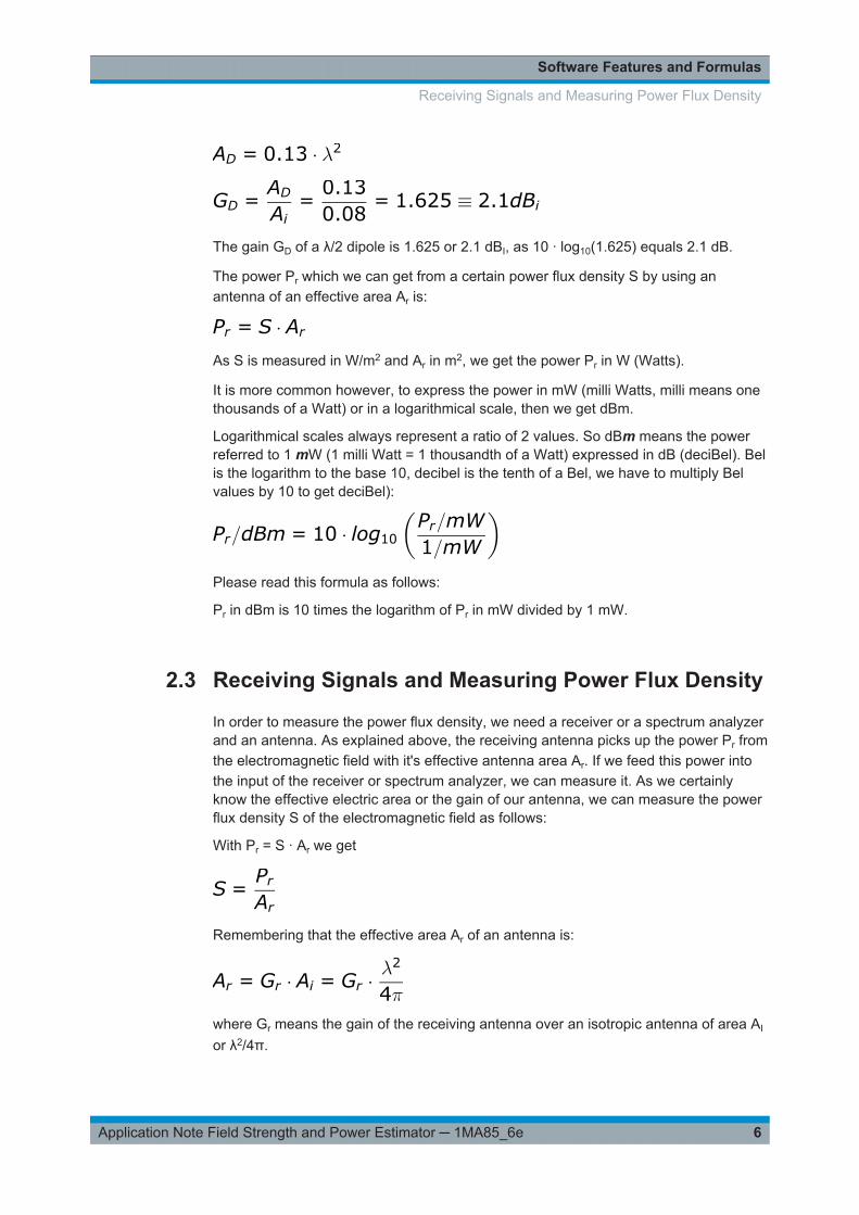
The gain GD of a λ/2 dipole is 1.625 or 2.1 dBI, as 10 · log10(1.625) equals 2.1 dB.
The power Pr which we can get from a certain power flux density S by using anantenna of an effective area Ar is:
As S is measured in W/m2 and Ar in m2, we get the power Pr in W (Watts).
It is more common however, to express the power in mW (milli Watts, milli means onethousands of a Watt) or in a logarithmical scale, then we get dBm.
Logarithmical scales always represent a ratio of 2 values. So dBm means the powerreferred to 1 mW (1 milli Watt = 1 thousandth of a Watt) expressed in dB (deciBel). Belis the logarithm to the base 10, decibel is the tenth of a Bel, we have to multiply Belvalues by 10 to get deciBel):
Please read this formula as follows:
Pr in dBm is 10 times the logarithm of Pr in mW divided by 1 mW.
2.3 Receiving Signals and Measuring Power Flux Density
In order to measure the power flux density, we need a receiver or a spectrum analyzerand an antenna. As explained above, the receiving antenna picks up the power Pr fromthe electromagnetic field with it's effective antenna area Ar. If we feed this power intothe input of the receiver or spectrum analyzer, we can measure it. As we certainlyknow the effective electric area or the gain of our antenna, we can measure the powerflux density S of the electromagnetic field as follows:
With Pr = S · Ar we get
Remembering that the effective area Ar of an antenna is:
where Gr means the gain of the receiving antenna over an isotropic antenna of area AI
or λ2/4π.
Receiving Signals and Measuring Power Flux Density
Software Features and Formulas
7Application Note Field Strength and Power Estimator ─ 1MA85_6e
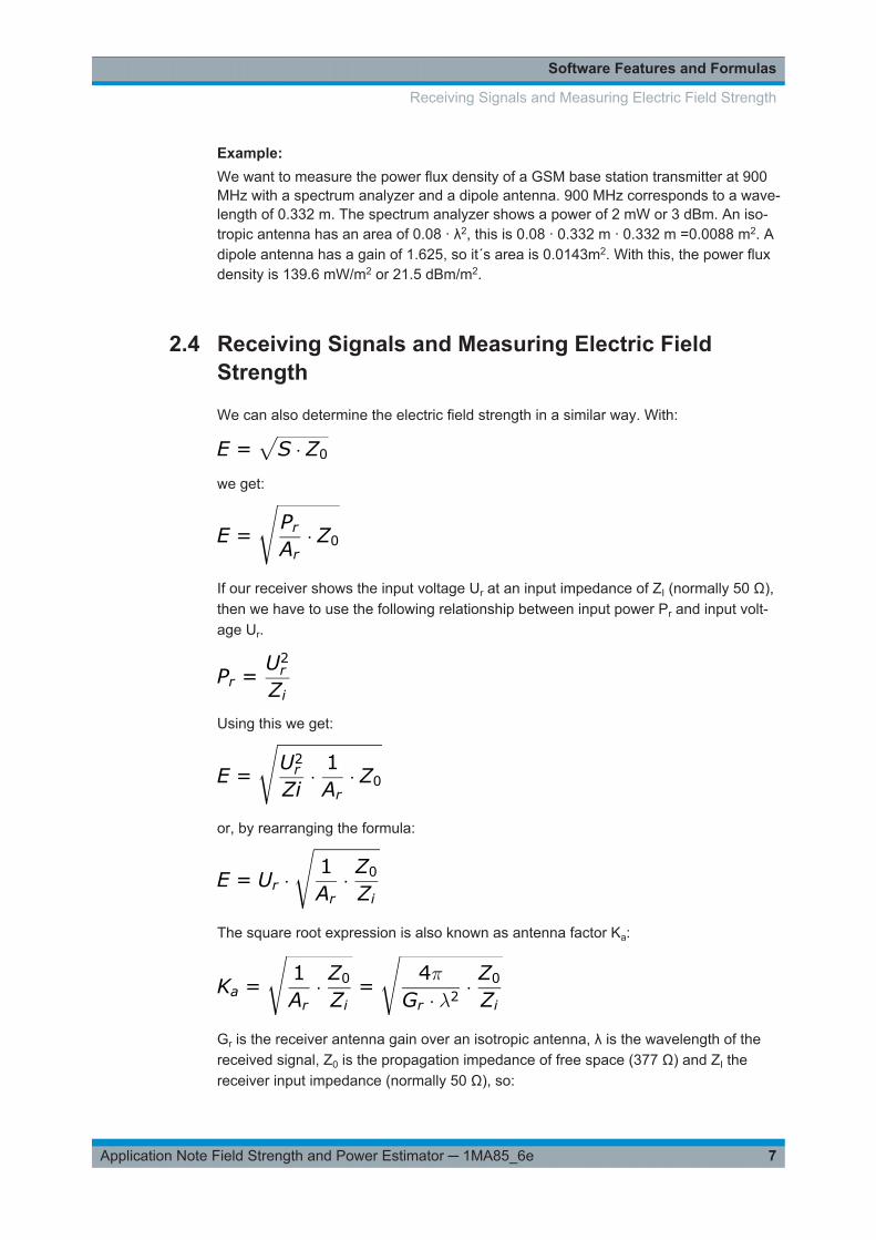
Example: We want to measure the power flux density of a GSM base station transmitter at 900MHz with a spectrum analyzer and a dipole antenna. 900 MHz corresponds to a wave-length of 0.332 m. The spectrum analyzer shows a power of 2 mW or 3 dBm. An iso-tropic antenna has an area of 0.08 · λ2, this is 0.08 · 0.332 m · 0.332 m =0.0088 m2. Adipole antenna has a gain of 1.625, so it´s area is 0.0143m2. With this, the power fluxdensity is 139.6 mW/m2 or 21.5 dBm/m2.
2.4 Receiving Signals and Measuring Electric FieldStrength
We can also determine the electric field strength in a similar way. With:
we get:
If our receiver shows the input voltage Ur at an input impedance of ZI (normally 50 Ω),then we have to use the following relationship between input power Pr and input volt-age Ur.
Using this we get:
or, by rearranging the formula:
The square root expression is also known as antenna factor Ka:
Gr is the receiver antenna gain over an isotropic antenna, λ is the wavelength of thereceived signal, Z0 is the propagation impedance of free space (377 Ω) and ZI thereceiver input impedance (normally 50 Ω), so:
Receiving Signals and Measuring Electric Field Strength
Software Features and Formulas
8Application Note Field Strength and Power Estimator ─ 1MA85_6e
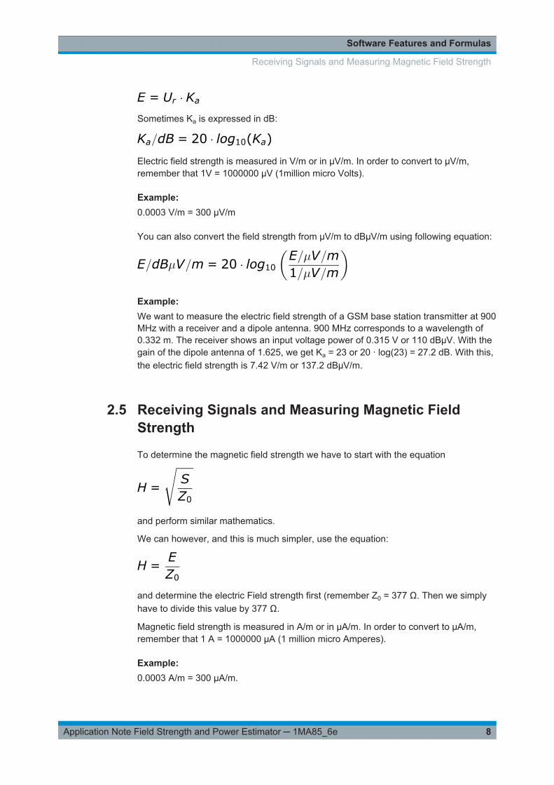
Sometimes Ka is expressed in dB:
Electric field strength is measured in V/m or in µV/m. In order to convert to µV/m,remember that 1V = 1000000 µV (1million micro Volts).
Example: 0.0003 V/m = 300 µV/m
You can also convert the field strength from µV/m to dBµV/m using following equation:
Example: We want to measure the electric field strength of a GSM base station transmitter at 900MHz with a receiver and a dipole antenna. 900 MHz corresponds to a wavelength of0.332 m. The receiver shows an input voltage power of 0.315 V or 110 dBµV. With thegain of the dipole antenna of 1.625, we get Ka = 23 or 20 · log(23) = 27.2 dB. With this,the electric field strength is 7.42 V/m or 137.2 dBµV/m.
2.5 Receiving Signals and Measuring Magnetic FieldStrength
To determine the magnetic field strength we have to start with the equation
and perform similar mathematics.
We can however, and this is much simpler, use the equation:
and determine the electric Field strength first (remember Z0 = 377 Ω. Then we simplyhave to divide this value by 377 Ω.
Magnetic field strength is measured in A/m or in µA/m. In order to convert to µA/m,remember that 1 A = 1000000 µA (1 million micro Amperes).
Example: 0.0003 A/m = 300 µA/m.
Receiving Signals and Measuring Magnetic Field Strength
Software Features and Formulas
9Application Note Field Strength and Power Estimator ─ 1MA85_6e
You can also convert the field strength from µA/m to dBµA/m using following equation
Example: We want to measure the magnetic field strength of a GSM base station transmitter at900 MHz with a receiver and a dipole antenna. 900 MHz corresponds to a wavelengthof 0.332 m. The receiver shows an input voltage power of 0.315 V or 110 dBµV. Deter-mine the electric field strength first as above. With the gain of the dipole antenna of1.625, we get Ka = 23 or 20 · log(23) = 27.2 dB. With this, the electric field strength is7.42 V/m. In order to get the magnetic field strength, we divide this value by 377 Ω andget 0.0197 A/m or 85.9 dBµA/m.
Receiving Signals and Measuring Magnetic Field Strength
Installing and Starting Field Strength and Power Estimator
10Application Note Field Strength and Power Estimator ─ 1MA85_6e
3 Installing and Starting Field Strength andPower EstimatorThe desktop version of Field Strength and Power Estimator is available for Mac OSXand Windows. Please read Chapter 3.1, "Mac OSX", on page 10 or Chapter 3.2,"Windows", on page 11 depending on your system.
Smartphone versions are also available. For more information please read Chapter 6,"Smartphone App Versions", on page 20.
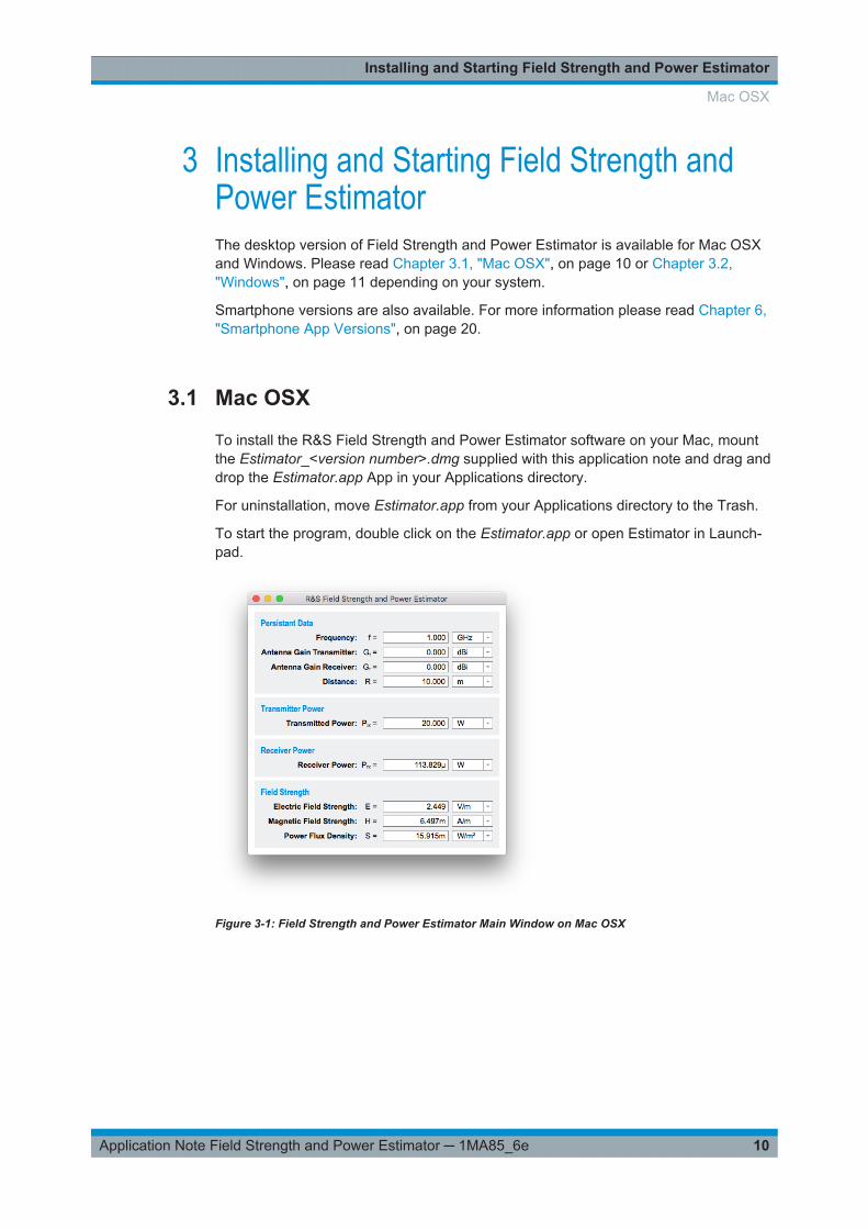
3.1 Mac OSX
To install the R&S Field Strength and Power Estimator software on your Mac, mountthe Estimator_<version number>.dmg supplied with this application note and drag anddrop the Estimator.app App in your Applications directory.
For uninstallation, move Estimator.app from your Applications directory to the Trash.
To start the program, double click on the Estimator.app or open Estimator in Launch-pad.
Figure 3-1: Field Strength and Power Estimator Main Window on Mac OSX
Mac OSX
Installing and Starting Field Strength and Power Estimator
11Application Note Field Strength and Power Estimator ─ 1MA85_6e
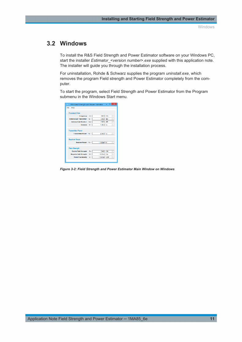
3.2 Windows
To install the R&S Field Strength and Power Estimator software on your Windows PC,start the installer Estimator_<version number>.exe supplied with this application note.The installer will guide you through the installation process.
For uninstallation, Rohde & Schwarz supplies the program uninstall.exe, whichremoves the program Field strength and Power Estimator completely from the com-puter.
To start the program, select Field Strength and Power Estimator from the Programsubmenu in the Windows Start menu.
Figure 3-2: Field Strength and Power Estimator Main Window on Windows
Windows
Operating the Program
12Application Note Field Strength and Power Estimator ─ 1MA85_6e
4 Operating the ProgramTo enter values for your calculation, select the appropriate field either with a left click ofyour mouse, by using the TAB key (forward order) or pressing Shift and TAB keysimultaneously (reverse order).
Since some values depend on previously entered values, you should use the followingorder:
1. Frequency
2. Gain of transmitting antenna
3. Gain of receiving antenna
4. Distance of transmitter to receiver
5. Transmitted power
Enter a value and confirm your entry by pressing the ENTER key. If you just want tochange only one digit of an existing entry, select this digit with your mouse or with the<> cursor keys.
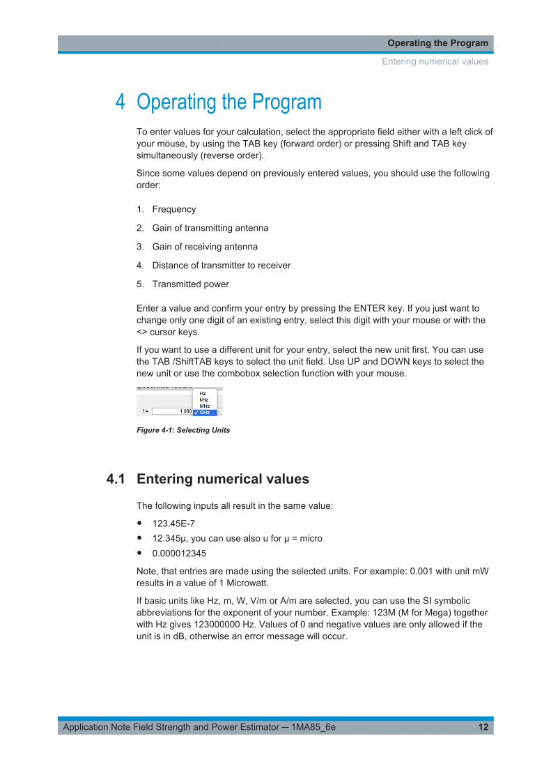
If you want to use a different unit for your entry, select the new unit first. You can usethe TAB /ShiftTAB keys to select the unit field. Use UP and DOWN keys to select thenew unit or use the combobox selection function with your mouse.
Figure 4-1: Selecting Units
4.1 Entering numerical values
The following inputs all result in the same value:
● 123.45E-7● 12.345µ, you can use also u for µ = micro● 0.000012345
Note, that entries are made using the selected units. For example: 0.001 with unit mWresults in a value of 1 Microwatt.
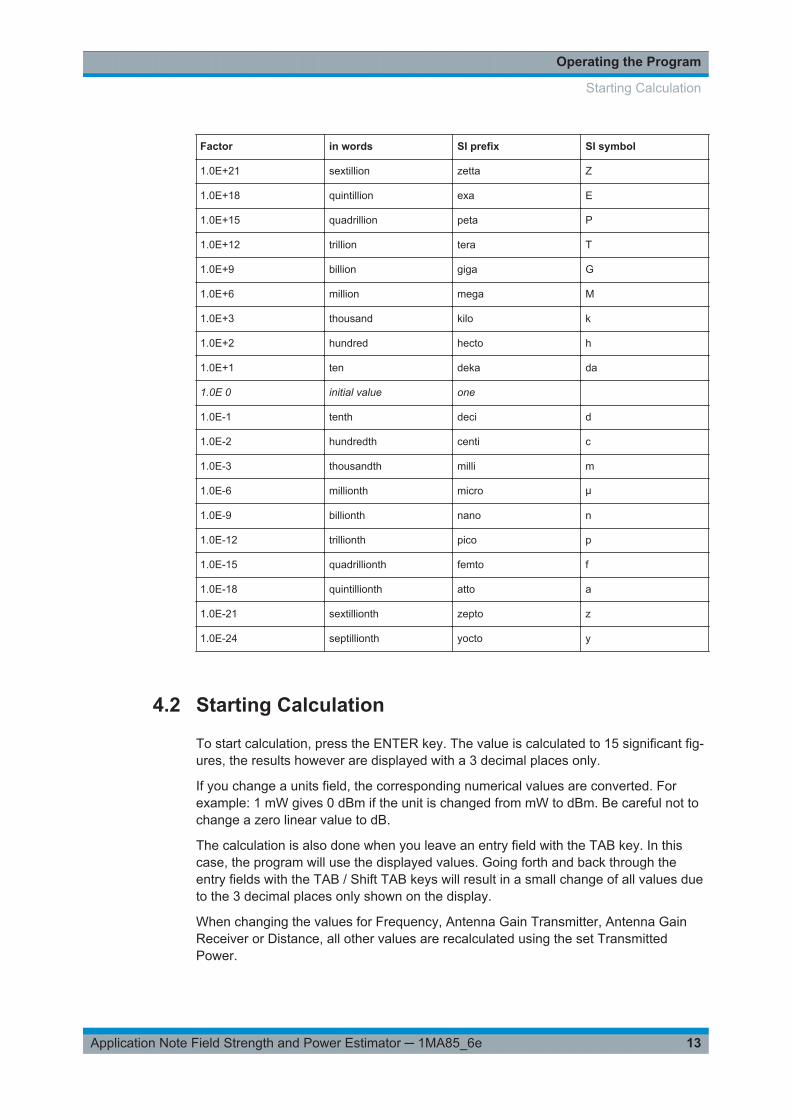
If basic units like Hz, m, W, V/m or A/m are selected, you can use the SI symbolicabbreviations for the exponent of your number. Example: 123M (M for Mega) togetherwith Hz gives 123000000 Hz. Values of 0 and negative values are only allowed if theunit is in dB, otherwise an error message will occur.
Entering numerical values
Operating the Program
13Application Note Field Strength and Power Estimator ─ 1MA85_6e
Factor in words SI prefix SI symbol
1.0E+21 sextillion zetta Z
1.0E+18 quintillion exa E
1.0E+15 quadrillion peta P
1.0E+12 trillion tera T
1.0E+9 billion giga G
1.0E+6 million mega M
1.0E+3 thousand kilo k
1.0E+2 hundred hecto h
1.0E+1 ten deka da
1.0E 0 initial value one
1.0E-1 tenth deci d
1.0E-2 hundredth centi c
1.0E-3 thousandth milli m
1.0E-6 millionth micro µ
1.0E-9 billionth nano n
1.0E-12 trillionth pico p
1.0E-15 quadrillionth femto f
1.0E-18 quintillionth atto a
1.0E-21 sextillionth zepto z
1.0E-24 septillionth yocto y
4.2 Starting Calculation
To start calculation, press the ENTER key. The value is calculated to 15 significant fig-ures, the results however are displayed with a 3 decimal places only.
If you change a units field, the corresponding numerical values are converted. Forexample: 1 mW gives 0 dBm if the unit is changed from mW to dBm. Be careful not tochange a zero linear value to dB.
The calculation is also done when you leave an entry field with the TAB key. In thiscase, the program will use the displayed values. Going forth and back through theentry fields with the TAB / Shift TAB keys will result in a small change of all values dueto the 3 decimal places only shown on the display.
When changing the values for Frequency, Antenna Gain Transmitter, Antenna GainReceiver or Distance, all other values are recalculated using the set TransmittedPower.
Starting Calculation

Operating the Program
14Application Note Field Strength and Power Estimator ─ 1MA85_6e
When changing one of the other values however, Frequency, Antenna Gain Transmit-ter, Antenna Gain Receiver and Distance will keep their values.
If you enter a Distance value, which is smaller than 0.159 times the wavelength (<λ/2π), the distance entry field becomes yellow as a warning for leaving the farfield condi-tion.
Figure 4-2: Near-Field Warning
4.3 Main / About Menu
Figure 4-3: Main Menu
On selecting Estimator > About Estimator (on Windows: Help > About), the followingmenu will show up:
Figure 4-4: About Menu
The tab "Legal Information" shows the conditions for using this program.
The tabs "Driver Information"(only Windows) and "System Information" will displayinformation on some installed drivers and your operating system. You can use the but-
Main / About Menu
Operating the Program
15Application Note Field Strength and Power Estimator ─ 1MA85_6e
ton "copy support information to clipboard" for debugging computer problems. Pasteyour clipboard contents to your mail system and send it to [email protected].
4.4 Save and Recall Settings
On exiting the program, all numerical values and units are saved to a file Estimator.iniin the AppData directory. Upon restart, these values are automatically restored. Forconvenience of operation, you can Save and Open Settings dialog. Use Default Set-tings to get a well defined program state.
Figure 4-5: File Menu
4.5 Help
Figure 4-6: Help Menu
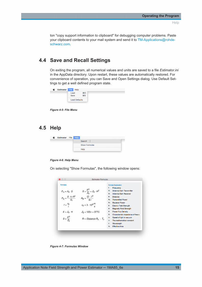
On selecting "Show Formulas", the following window opens:
Figure 4-7: Formulas Window
Help

Operating the Program
16Application Note Field Strength and Power Estimator ─ 1MA85_6e
For convenient use of the program and recalling the explanation of the calculation for-mulas, selecting Help will show you this documentation.
Help
Some Examples
17Application Note Field Strength and Power Estimator ─ 1MA85_6e
5 Some ExamplesThe following examples show some of the additional capabilties of the program FieldStrength and Power Estimator.
5.1 Determining the Propagation Attenuation between 2Antennas
You can determine the attenuation of an undistorted wave progagation as follows:
Enter the frequency, set the antenna gains of transmit and receive antennas to 0 dBi
and enter the distance. If you enter 0 dBm for transmitted power, the field ReceivedPower in dBm will show the value of the attenuation in dB.
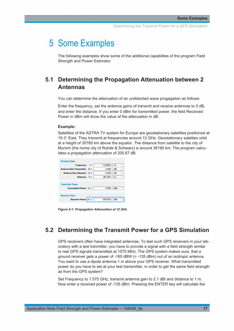
Example: Satellites of the ASTRA TV system for Europe are geostationary satellites positioned at19.3° East. They transmit at frequencies around 12 GHz. Geostationary satelites orbitat a height of 35785 km above the equator. The distance from satellite to the city ofMunich (the home city of Rohde & Schwarz) is around 38190 km. The program calcu-lates a propagation attenuation of 205.67 dB.
Figure 5-1: Propagation Attenuation at 12 GHz
5.2 Determining the Transmit Power for a GPS Simulation
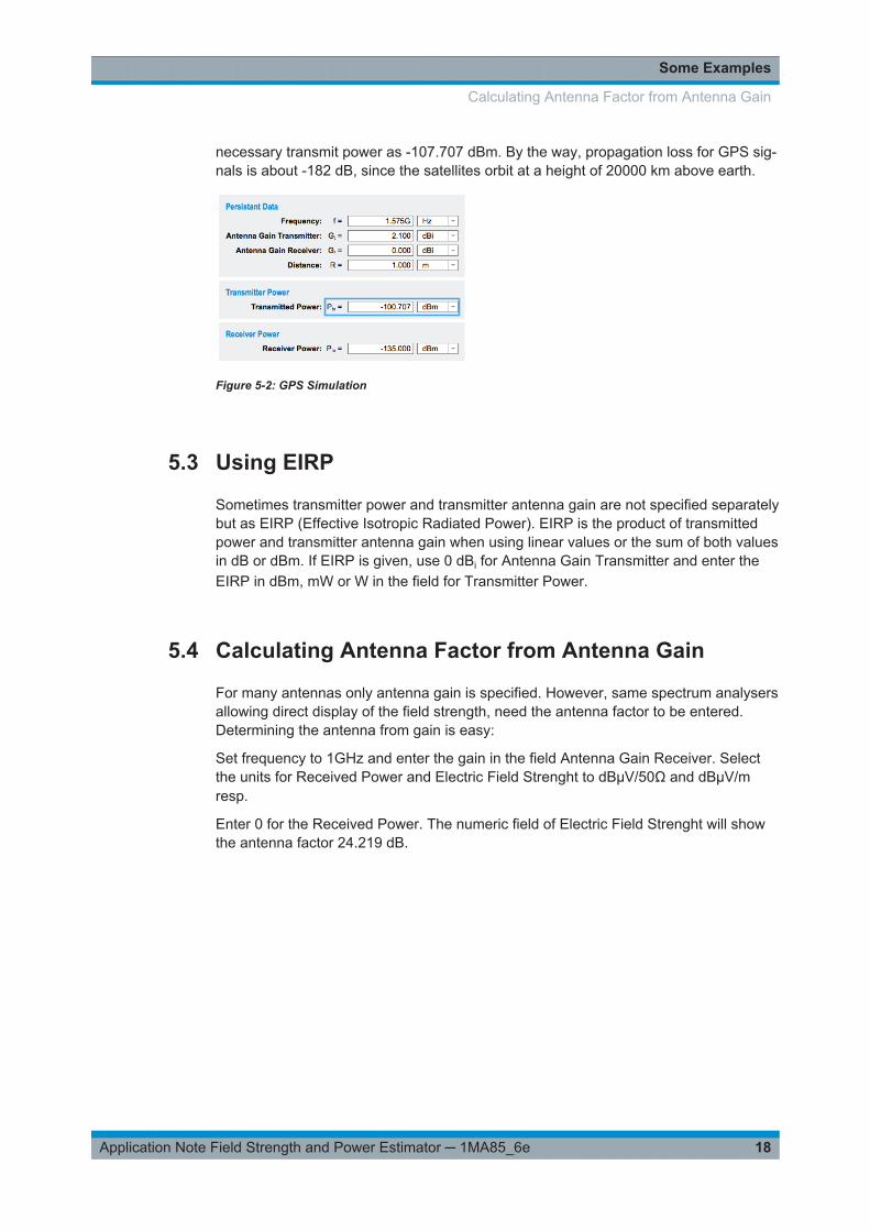
GPS receivers often have integrated antennas. To test such GPS receivers in your lab-oratory with a test tranmitter, you have to provide a signal with a field strength similarto real GPS signals transmitted at 1575 MHz. The GPS system makes sure, that aground receiver gets a power of -165 dBW (= -135 dBm) out of an isotropic antenna.You want to use a dipole antenna 1 m above your GPS receiver. What transmittedpower do you have to set at your test transmitter, in order to get the same field strengthas from the GPS system?
Set Frequency to 1.575 GHz, transmit antenna gain to 2.1 dBi and distance to 1 m.Now enter a received power of -135 dBm. Pressing the ENTER key will calculate the
Determining the Transmit Power for a GPS Simulation
Some Examples
18Application Note Field Strength and Power Estimator ─ 1MA85_6e
necessary transmit power as -107.707 dBm. By the way, propagation loss for GPS sig-nals is about -182 dB, since the satellites orbit at a height of 20000 km above earth.
Figure 5-2: GPS Simulation
5.3 Using EIRP
Sometimes transmitter power and transmitter antenna gain are not specified separatelybut as EIRP (Effective Isotropic Radiated Power). EIRP is the product of transmittedpower and transmitter antenna gain when using linear values or the sum of both valuesin dB or dBm. If EIRP is given, use 0 dBi for Antenna Gain Transmitter and enter theEIRP in dBm, mW or W in the field for Transmitter Power.
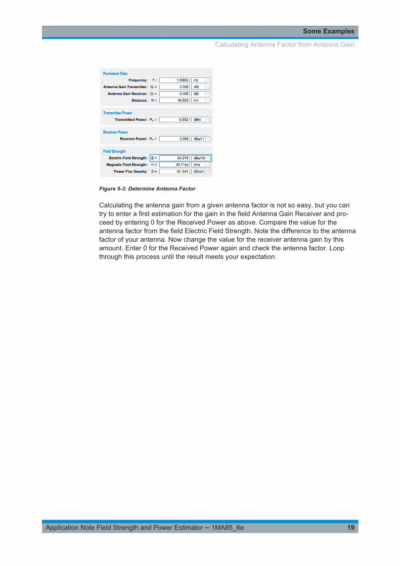
5.4 Calculating Antenna Factor from Antenna Gain
For many antennas only antenna gain is specified. However, same spectrum analysersallowing direct display of the field strength, need the antenna factor to be entered.Determining the antenna from gain is easy:
Set frequency to 1GHz and enter the gain in the field Antenna Gain Receiver. Selectthe units for Received Power and Electric Field Strenght to dBµV/50Ω and dBµV/mresp.
Enter 0 for the Received Power. The numeric field of Electric Field Strenght will showthe antenna factor 24.219 dB.
Calculating Antenna Factor from Antenna Gain
Some Examples
19Application Note Field Strength and Power Estimator ─ 1MA85_6e
Figure 5-3: Determine Antenna Factor
Calculating the antenna gain from a given antenna factor is not so easy, but you cantry to enter a first estimation for the gain in the field Antenna Gain Receiver and pro-ceed by entering 0 for the Received Power as above. Compare the value for theantenna factor from the field Electric Field Strength. Note the difference to the antennafactor of your antenna. Now change the value for the receiver antenna gain by thisamount. Enter 0 for the Received Power again and check the antenna factor. Loopthrough this process until the result meets your expectation.
Calculating Antenna Factor from Antenna Gain

Smartphone App Versions
20Application Note Field Strength and Power Estimator ─ 1MA85_6e
6 Smartphone App Versions
Figure 6-1: Spartphone Versions
The app can be downloaded free of charge from different app-stores, depending onyour mobile operating system. To find the app easily, please use search terms "Rohde& Schwarz" or "Field Strength Estimator" or click on the following links to access theapp landing page directly:
● iOS:https://itunes.apple.com/app/id364229792
● Android:https://play.google.com/store/apps/details?id=com.rohdeschwarz.android.estimator
● Windows Phone:https://www.microsoft.com/store/apps/9nblggh0fwb1

Rohde & Schwarz
21Application Note Field Strength and Power Estimator ─ 1MA85_6e
7 Rohde & SchwarzThe Rohde & Schwarz electronics group offers innovative solutions in the followingbusiness fields: test and measurement, broadcast and media, secure communications,cybersecurity, radiomonitoring and radiolocation. Founded more than 80 years ago,this independent company has an extensive sales and service network and is presentin more than 70 countries.
The electronics group is among the world market leaders in its established businessfields. The company is headquartered in Munich, Germany. It also has regional head-quarters in Singapore and Columbia, Maryland, USA, to manage its operations inthese regions.
Sustainable product design
● Environmental compatibility and eco-footprint● Energy efficiency and low emissions● Longevity and optimized total cost of ownership
Certified Quality Management
ISO 9001Certified Environmental Management
ISO 14001
Regional contact
● Europe, Africa, Middle East - [email protected] +49 89 4129 12345
● North America - [email protected] 1-888-TEST-RSA (1-888-837-8772)
● Latin America - [email protected] +1-410-910-7988
● Asia/Pacific - [email protected] +65 65 13 04 88
● China - [email protected] +86-800-810-8228 / +86-400-650-5896
Headquarters
Rohde & Schwarz GmbH & Co. KG
Mühldorfstraße 15 | D - 81671 München
+ 49 89 4129 - 0 | Fax + 49 89 4129 – 13777
www.rohde-schwarz.com
This application note and the supplied programs may only be used subject to the conditions of use set forthin the download area of the Rohde & Schwarz website.
R&S® is a registered trademark of Rohde & Schwarz GmbH & Co. KG. Trade names are trademarks of theowners.