Embed Size (px)
Citation preview

FIELD TESTING AND NUMERICAL MODELING OF A HYBRID COMPOSITE
BEAM BRIDGE IN VIRGINIA
Devin K. Harris, Ph.D. Amir Gheitasi, Ph.D. John M. Civitillo
Assistant Professor Postdoctoral Research Associate Nuclear Engineer
Department of Civil and
Environmental Engineering
Department of Civil and
Environmental Engineering
Norfolk Naval Shipyard
University of Virginia University of Virginia
Charlottesville, VA 22904 Charlottesville, VA 22904 Portsmouth, VA 23709 U.S.A. U.S.A. U.S.A.
[email protected] [email protected] [email protected]
KEYWORDS: Hybrid Composite Beam (HCB), Live Load Testing, In-service Bridge Performance,
Wireless Instrumentation, Structural Health Monitoring.
ABSTRACT
A relatively new technology, Hybrid Composite Beams (HCB), are being deployed in bridges throughout
North America as an alternative to traditional materials. A HCB is comprised of a glass-fiber reinforced
polymer (FRP) box shell containing a tied parabolic concrete arch. In a girder-type bridge superstructure,
these beams can support a conventional reinforced concrete deck, while the inclined stirrups provide shear
integrity and enforce composite action between the HCBs and the concrete deck. The HCB system offers
an efficient use of materials, ease of construction, and resistance to corrosion, making the system ideal for
sustainable bridge design.
This research study focuses on evaluating the in-service performance of a new HCB bridge in Virginia.
In the corresponding evaluation program, the bridge was tested under live-load conditions and monitored
using a suite of sensors. Results from the experimental program were used to better understand the bridge
behavior including how the loads are transmitted, both at the system and element levels. Moreover, the
test results provided validity to the rational design approach employed for this system, but also highlighted
some of the key non-composite system behavior that warrant further consideration in future design. In
addition to the testing program, a detailed finite element model was generated to support the experimental
data and provide additional insight into the system behavior characteristics.
INTRODUCTION
In recent years, the challenges related to the transportation infrastructure network in the United States
have become an area of national focus. Transportation agencies are dealing with an aging infrastructure
that is documented to be in a poor condition state, but are also faced with limited resources available to
address the challenges (ASCE 2013; FHWA 2013). Within the bridge community, it is common
knowledge that the solution to these challenges will not come from a single source, but rather a strategic
mix of innovative solutions that include sustainable and adaptable designs, durable materials, and non-
invasive or accelerated construction (Carbonell Munoz et al. 2014; Fuhrman et al. 2014; Grace et al. 2013;
Harris et al. 2015; Harris et al. 2008; Russell 2013). For widespread adoption, however, the solution needs
to be cost effective and accepted by the practicing community, features which have hampered many of
these previous innovations.
The hybrid composite beam (HCB) system is a recent innovation that has the potential to address many
of the challenges and is also gaining acceptance in the bridge community. When incorporated in a
traditional beam bridge design, individual HCBs serve as the primary superstructure members or girders
and can be made composite with a traditional reinforced concrete deck. Each HCB, as illustrated in Fig.1,
consists of a glass fiber reinforced polymer (FRP) box shell that encases a passively tied concrete arch
(Hillman 2003). The tie reinforcement is unstressed prestressing strand (passive) that is integrated into the
FRP shell during fabrication, while the arch is typically made of self-consolidating concrete. With this

design, the concrete arch resists the internal compression forces due to self-weight and additional
construction loads, while the steel is intended to tie the arch together and carry internal tensile forces
imposed by the live loads. The primary shear resistance is provided by the combination of a monolithic
concrete fin that extends from the arch along the span and distributed reinforcing bars oriented at 45° from
vertical and anchored within the arch. The shear reinforcement also provides the composite connection
between the HCBs and a conventionally reinforced concrete deck.
Fig. 1 Components of hybrid composite beam.
The anticipated benefits of this system are derived from the efficient use of materials, lightweight design,
corrosion resistance, and use in accelerated construction projects to minimize the disruption to traffic flow,
when compared to conventional bridge designs. Although there has been a great deal of recent interest in
the application of this technology, the complex behaviors of the system and its response under standard
in-situ loading scenarios are still not completely understood and require further evaluation. For the bridge
community to accept the HCB system as a viable solution, there is a critical need to understand in-service
behavior of the system and confirm the assumptions that are being made in the current design
methodology.
BACKGROUND AND RESEARCH SIGNIFICANCE
The first investigation of hybrid composite girders was sponsored by the Transportation Research Board
as part of the Innovations Deserving Exploratory Analysis (IDEA) program. A companion experimental
study was conducted in Colorado, on a single prototype beam and a complete railroad bridge structure
(Hillman 2003; Hillman 2008). Results of these early tests validated the predictable structural behavior of
the HCB for its intended purpose in a bridge structure. In 2010, a large-scale project was described (Snape
and Lindyberg 2009) to construct an eight-span HCB bridge with the total length of 165 m (540 ft) in
Maine. Prior to construction, a single beam was tested for service and fatigue loads as well as the ultimate
capacity and failure mode. Results from this study demonstrated that the tested beam behaved as predicted,
although it was stiffer in the test due to the FRP wings, which is being neglected in design calculations
(Hillman 2012). The HCB technology was also used to construct three bridges in Missouri. Along with
the construction of these bridges, the Missouri Department of Transportation supported an exploratory
program, including live-load testing and finite element modeling to evaluate the in-service behavior of the
constructed HBC bridge superstructures (Myers et al. 2014). The results of this work suggested that the
HCB does not exhibit traditional flexural beam behavior, as the relative movements between the internal
components affect the flexural behavior of the girders.
In Virginia, the first HCB bridge superstructure was constructed in 2013 as a replacement to a
conventional concrete bridge, by the means of reusing the existing abutments and substructure. Virginia
Department of Transportation funded a multi-phase research project spearheaded by Virginia Polytechnic
Institute and State University (Virginia Tech) and the University of Virginia (UVa). Virginia Tech was
tasked with the investigation of the HCB system in a laboratory setting, and their study focused on the
element-level behavior, evaluation of flexural design methodology, reduced full-scale system-level
response, and load path generated between the concrete arch and FRP shell, at various phases throughout
the construction of the system and a variety of loading scenarios (Ahsan 2012; Nosdall 2013). The results
obtained from this experimental study also demonstrated that the concrete arch does not act compositely
with the rest of the HCB system. Also noted was the importance of including the FRP wings and the
concrete fin in the design and analysis of the HCB system, since they both contribute to the flexural
resistance. The companion study at UVa focused on evaluating the system behavior of the HCB under in-
service conditions, which is the focus of this paper.
METHOD OF STUDY
The purpose of this study was to use traditional live-load testing strategies and finite element modeling to
characterize the in-service structural behavior of the HCB system used on a skewed bridge superstructure
constructed in Virginia. To establish a mechanism for monitoring the in-service behavior, a suite of
external and internally embedded sensors were deployed on the structure at strategic locations. The
behavior characteristics of interest included the flexural lateral load distribution behavior, the element
load sharing behavior, and the dynamic load amplification of this specific HCB bridge system. To validate
the the design assumptions with respect to live load performance and dynamic response of this structure,
results obtained from the experimental investigation were compared to provisions with the AASHTO
provisions (AASHTO 2002; AASHTO 2012). In addition to the experimental investigation, a detailed
numerical study was also performed on the tested structure to support and complement the experimental
results, while providing additional insight into the system-level behavior characteristics.
SELECTED STRUCTURE
The selected structure was a short span HCB bridge constructed on Route 205 in Colonial Beach, Virginia.
For this bridge, the construction took place in series of phases including off-site fabrication of the HCBs,
shipping and concrete filling, as well as side-by-side installment and placement of the deck system
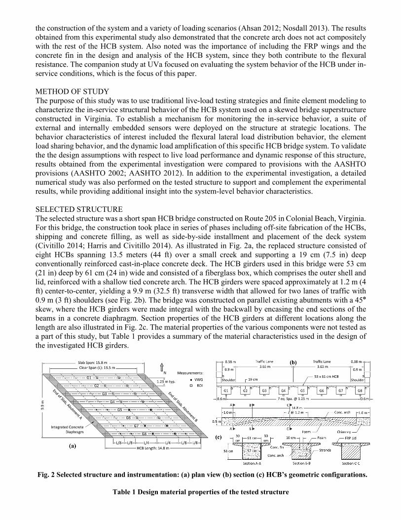
(Civitillo 2014; Harris and Civitillo 2014). As illustrated in Fig. 2a, the replaced structure consisted of
eight HCBs spanning 13.5 meters (44 ft) over a small creek and supporting a 19 cm (7.5 in) deep
conventionally reinforced cast-in-place concrete deck. The HCB girders used in this bridge were 53 cm
(21 in) deep by 61 cm (24 in) wide and consisted of a fiberglass box, which comprises the outer shell and
lid, reinforced with a shallow tied concrete arch. The HCB girders were spaced approximately at 1.2 m (4
ft) center-to-center, yielding a 9.9 m (32.5 ft) transverse width that allowed for two lanes of traffic with
0.9 m (3 ft) shoulders (see Fig. 2b). The bridge was constructed on parallel existing abutments with a 45°
skew, where the HCB girders were made integral with the backwall by encasing the end sections of the
beams in a concrete diaphragm. Section properties of the HCB girders at different locations along the
length are also illustrated in Fig. 2c. The material properties of the various components were not tested as
a part of this study, but Table 1 provides a summary of the material characteristics used in the design of
the investigated HCB girders.
Fig. 2 Selected structure and instrumentation: (a) plan view (b) section (c) HCB’s geometric configurations.
Table 1 Design material properties of the tested structure

Deck Shear
Reinf.
HCB
Conc. Reinf. Arch Strands FRP Shell Polyiso Foam
E (GPa) 26.4 29 29 30.4 27.5 E11: 21.4 E22: 18.5 E11: 8.4 E33: 3.2 E33: 3.2
ν 0.18 0.3 0.3 0.18 0.3 ν12: 0.3 ν 21: 0.26 ν12: 0.33 ν13: 0.33 ν23: 0.31
f'c (MPa) 31 - - 41.4 - - - - - -
fy (MPa) - 415 415 - - - - - - -
fu (MPa) - - - - 1860 - - - - -
EXPERIMENTAL INVESTIGATION
Instrumentation
Figs. 2a and 2b illustrate the implemented instrumentation plan for this structure, which was developed to
satisfy the testing program requirements and establish a mechanism for monitoring the in-service behavior
of the system. The program required a variety of sensors with multiple data acquisition systems with
different functionalities. The first system utilized a series of data-loggers and was based on the use of
internally mounted vibrating wire gauges (VWGs) in conjunction with a Campbell Scientific Inc. (CSI)
data acquisition system (DAQ) that were installed throughout the fabrication and construction phases of
the girders and bridge deck. A series of non-corrosive 3D printed frames, made of acrylonitrile butadiene
styrene, were used to position the gauges at the desired depths within the voided conduits such that the
VWGs were aligned longitudinally with the beam, as depicted in Fig.3. A total of 48 VWG locations were
selected and these VWGs were installed in three of the eight girders (G5, G7, and G8) so as to minimize
the interference with the construction of the girders. In addition, nine gauges were longitudinally affixed
to the deck reinforcement mat (at 100 cm/4 in depth) at companion locations to the mid-span and quarter-
span locations of the three selected girders. Table 3 illustrates and describes the location of the gauges
within the HCB cross-section. The resulting system of gauges was expected to provide a comprehensive
measure of the overall internal system behavior including location of the neutral axis and level of
composite action that exists between the deck and girders.
(a) (b) (c) (d)
Fig. 3 Internal VWG placement: (a) tension level (b) concrete arch (c) in concrete fin (d) concrete deck
Table 2 VWG instrumentation location matrix
Location G5 G7 G8
East 1/8 L - - R, CT, CB
East 1/4 L D, CT, CB, S D, CT, CB, S D, CT, CB, S
1/2 L D, CT, CB, S D, CT, CB, S D, CT, CB, S
West 1/4 L D, CT, CB, S D, CT, CB, S D, CT, CB, S
West 1/8 L R, CT, CB - R, CT, CB
D: Deck; CT: upper arch; CB: lower arch; S: tension strand; R: rosette within fin
The second data acquisition system utilized a rapidly deployable wireless system by Bridge Diagnostics
Inc. (BDI). Externally mounted strain gauges were placed on the bottom flange and web of each girder on
all of the girders at midspan as well as East quarter-span (Fig. 4a). Two additional external BDI strain
gauges were placed on the parapet at mid-span of the structure to investigate the level of stiffening
provided by the barriers to the system. These gauges were used to create an external strain profile that
could be aligned with the internal strain profiles and contribute to the evaluation of the load sharing

behavior of the individual HCB elements. On the day of the test, the BDI wire leads were connected to
the wireless nodes (4 gauges per node) that relayed to a central base station (Fig. 6b). The lead wires from
the internally mounted VWGs were also connected to the appropriate CSI data-logger for periodic
measurements (Fig. 4c). In addition to the instrumentation on the bridge, a BDI product called an
Autoclicker was attached to the wheel well of the load test truck to track the longitudinal position of the
truck as it crossed the bridge (Fig. 4d)
(a) (b) (c) (d)
Fig. 4 External BDI installation and final test preparation: (a) gauge alignment (b) BDI wireless nodes (c)
CSI data-loggers setup (d) truck autoclicker
Live-Load Testing
The load test was performed by driving load vehicles East to West across the bridge at predetermined
transverse positions (see Fig. 5a). These vehicles were standard VDOT tandem-axle dump trucks (Fig.
5b), which were loaded with gravel and used for the quasi-static tests and the dynamic tests. During quasi-
static testing, the truck driver was guided at a crawl speed (< 8 kmph or 5 mph) to ensure that the
passenger’s side wheel path aligned with the designated transverse locations (Fig. 5c). Each transverse
run was performed a total of three times, always pausing on the third run for 60 seconds at a pre-designated
longitudinal location close to the mid-span of the girder nearest the driver’s side wheel path. The pause
during the third run allowed the VWGs to collect a true static measurement in the loaded configuration.
During the static load testing, the data was captured at 25 Hz for the BDI system and 100 Hz for the CSI
system. In addition to the quasi-static testing, a series of dynamic truck runs were also performed to
measure the dynamic characteristics of this structure. This paper will exclusively focus on the quasi static
test and aims to interpret the corresponding collected data to describe the overall load distribution
characteristics as well as the element load sharing behavior of the selected structure. Further information
with regards to the dynamic behavior of HCB systems can be found in previous works of the authors
(Civitillo 2014; Harris and Civitillo 2014).
Fig. 5 Load testing (a) transverse load positions (b) truck configuration (c) guiding truck driver

FINITE ELEMENT SIMULATION
Modeling Details/Assumptions
A commercial finite element package, ANSYS 14.0, was used in this study to generate a numerical model
for the tested structure. Due to the complex geometry of the HBCs together with the skewed configuration
of the selected bridge superstructure, all of the geometrical properties included in the model were extracted
directly from the VDOT plans and the corresponding design documents (VDOT 2011). In the model, the
concrete components of the bridge system, including the slab and the arch within the HCBs, were modeled
using eight-node solid elements (SOLID65). Uniaxial tension-compression spar elements, LINK180, were
used to discretely model the internal reinforcement within the deck and the arch, as well as the tensile tie
strands at the bottom of the HCB girders. The foam sections surrounding the concrete arch were also
included in the model using 3D brick elements (SOLID185). Four-node reduced integration shell
elements, SHELL181, were used to model different parts of the FRP box shell which encases the
components of the HCB girders. Linear elastic material properties assumed for each of these component
were extracted from the design documents and included in the model (see Table 1). During the
construction, each HCB was infused with a vinyl ester resin using the vacuum assisted resin transfer
method (VARTM). As a result, perfect bond was assumed for the surface-to-surface contact elements that
provided connections between the FRP shell box, tie reinforcement and the foam sections (Snape and
Lindyberg 2009). In addition. the concrete arch was also assumed to be in ideal fully-bonded connection
with the foam sections. Fig. 6 illustrates the details of the numerical model developed for a single HBC
girder. The bridge model was then developed by replicating the beam element following the skewed
configuration of the system. Similar surface-to-surface contact algorithm was used in the model to
simulate the interaction between the reinforced concrete deck and eight HCBs. With no evidence of loss
in the composite action of the system during the live-load testing, fully-bonded characteristics were
assigned to the implemented contact elements (Aboelseoud and Myers 2014). It should be noted that the
wings of the FRP lid within HCBs were not included in the model, as they provided a stay-in-place
formwork for the deck during the construction, with no major contribution to the structural integrity and
system behavior subjected to service loads.
Fig. 6 Developed FE model for HCB (shrink view).
Numerical Analysis
The developed numerical model was fully restrained at the either end of the HCB’s FRP box shells to
simulate the continuous integral abutment and the associated concrete diaphragm of the actual structure
(see Fig. 2a). Based on the loading configurations illustrated in Fig. 5a, the model was loaded, in eight
different analysis cases, with a series of concentrated loads applied over the tire patch area independent
of the generated mesh pattern of the concrete deck (Gheitasi and Harris 2014). The longitudinal positions
of the applied loads in the model were defined based on the data collected from the autoclicker node during

the static run for each load case. The small values of strains collected during the live-load test indicated
that the system is behaving within the linear-elastic range under the impact of service loads, but also put
aside the necessity to perform a large-deformation (nonlinear geometry) analysis. As a result, linear static
analysis with small displacements were selected in this study for the numerical investigation of the tested
HCB bridge superstructure under the assumed loading scenarios.
RESULTS AND DISCUSSION
Following completion of the load testing program and the numerical analysis, the data was retrieved and
post-processed to evaluate the specific behavioral characteristics including lateral load distribution and
internal/external load sharing behavior of the selected structure. Additional details on these characteristics
together with comparison of the results to those recommended by the AASHTO LRFD specification are
provided in the following sub-sections.
Lateral Load Distribution Behavior
In this study, the flexural lateral load distribution behavior was analyzed to help evaluate the in-service
behavior of the HCB bridge because such in-situ performance is critical to the end user, as there are very
few HCB bridges currently in use. Within a typical beam bridge structure, the expected behavior under
load is that the girders most directly under the loading will resist the majority of the load, with the girders
further away resisting less (Gheitasi and Harris 2014; Harris and Gheitasi 2013). For the HCB load testing
program this phenomena is illustrated in Fig. 7, which presents a sample of time series strain data collected
at midspan of the structure for each of the three runs for LC A and LC H, using external BDI stain gauges.
Similar trends were observed in both of these representative cases, where the further girders to the applied
loads contribute less to the overall load distributing mechanism of the system. However, it is interesting
to note that G1 and G8 would be expected to also have significant response under the assumed loading
scenarios (LC A and LC H, respectively), but this effect appears to be somewhat muted by the influence
of the parapet. The complete set of strain responses at midspan and quarter point maintain different
characteristics affected by skew, loading positions, and support conditions of the tested bridge, which are
available in Civitillo (Civitillo 2014).
Fig. 7 Time series strain data at midspan for LC A and LC H.
Using the occurrence of maximum strain within the most heavily loaded beam as the point of reference,
the average transverse lateral load sharing behavior throughout the bridge cross section was evaluated for
various load cases. Fig. 8 illustrates a sample of this data for three representative cases (LC D, LC F, and

LC H) at midspan of the structure. As previously highlighted, the most heavily loaded girders experience
the greatest bottom flange strain, while girders further away experience less. Also included in Fig. 8, are
the results obtained from the corresponding numerical analysis, considering the impact of parapets on the
lateral load distribution mechanism of the system. FEA1 represents the model without parapets, while
FEA2 represents the model with parapets included. For the exterior beams, it is evident from the decrease
in strain that the parapets carry a significant fraction of the applied loads. Average compressive strains
(up to -31 µε) collected from the external gauges attached to the critical parapet also support the fact that
the lateral distribution behavior of the exterior girders are significantly affected by the stiffness of the
parapets. Analogous results have been also reported by Aboelseoud and Myer (Aboelseoud and Myers
2014), who performed similar live load test program on a HCB bridge superstructure in the State of
Missouri.
When comparing the strains observed on the exterior (BDI) with those measured internally (VWG) at the
level of strands (S), the VWG strains do not consistently match the trend or magnitude of strain. The
internal strain readings are consistently lower than the external FRP strains, with the exception of the
exterior girder (G8). The cause of this non-correspondence is not definite, but may be attributed to the
non-composite behavior of the HCB components. One possible theory is that the tension steel pulls away
from the FRP shell because of the lack of support provided by the foam at mid-span. In other words, as
the beam generates curvature in flexure, the steel strands may pull away from the FRP shell to remain as
linear as possible in tension, while the curvature of the bottom flange of the FRP is enforced by the
stiffness of the side webs tying into the remainder of the system and the curvature of the deck.
Fig. 8 Strain distribution across midspan for LC D, LC F, and LC H.
The flexural lateral load distribution factors at the midspan of the structure were evaluated based on the
results obtained from the experimental and numerical studies. The maximum distribution factors for each
run and each of the load configurations are summarized in Table 3. Also included in this table are the
critical distribution factors that were calculated based on the AASHTO LRFD (AASHTO 2012) as well
as AASHTO Standard Specification (AASHTO 2002). It should be emphasized that these specifications
do not contain provisions for this type of system, but when considering the anticipated HCB element
behavior, it would be expected that the system behavior might mimic that of a conventional slab-girder
bridge system such as a concrete deck on reinforced concrete girders (AASHTO Type A) or a concrete
deck on box girders (AASHTO Type B). For the load testing program, the controlling distribution factor
for the interior girder resulted from LC A, while the controlling value for the exterior girder occurred for
LC H. For the numerical analysis, the controlling distribution factor for both interior and exterior girders
resulted for LC H. Comparing the experimental and numerical results indicates that the model
overestimates the critical distribution behavior for the exterior girder, while underestimate the
corresponding value for the interior girder. Moreover, when comparing the measured distribution behavior
from the live-load testing program to the code specified values with adjustments for skew, it is clear that
AASHTO LRFD Type B designation and AASHTO standard specification yield conservative estimates
for exterior girders, while only the AASHTO LRFD Type B design value is conservative for the
controlling interior distribution factor.

Table 3 Summary of mid-span flexural distribution factors (lanes/beam)
Truck Position Run 1 Run 2 Run 3 FE Analysis (FEA2)
Ext. Int. Ext. Int. Ext. Int. Ext. Int.
LC A 0.166 0.297 0.177 0.336 0.211 0.375 0.218 0.276
LC B 0.135 0.315 0.131 0.308 0.127 0.259 0.161 0.247
LC C 0.096 0.262 0.093 0.249 0.082 0.201 0.073 0.233
LC D 0.060 0.220 0.060 0.227 0.057 0.180 0.028 0.256
LC E 0.051 0.200 0.050 0.201 0.065 0.182 0.038 0.268
LC F 0.102 0.227 0.105 0.231 0.105 0.233 0.110 0.247
LC G 0.162 0.279 0.168 0.281 0.185 0.275 0.237 0.254
LC H 0.227 0.296 0.227 0.297 0.257 0.286 0.365 0.304
AASHTO Provision Ext. Int.
LRFD – Type A 0.247 0.360
LRFD – Type B 0.288 0.306
Standard Specification 0.371 0.371
Note: critical distribution values are highlighted in bold
Element Load Sharing Behavior
An understanding of the internal load sharing behavior is essential for maintenance and decision-making
processes of the HCB system as it ages. In this study, the internal and external instrumentation allowed
for the measurement of the strain during live load testing and provided critical information on the load
sharing behavior between the concrete arch, FRP shell, and reinforcing steel, as well as the location of the
neutral axis of the composite cross-section. Fig. 9 illustrates the midspan strain profile through the depth
of the cross-section for beams 5, 7, and 8 subjected to Load Cases F, G, and H. These load cases were
selected because the load truck was in close proximity to the three girders that maintained both internal
and external instrumentation, and thus yielded the most relevant results.
G5 G7 G8
LC F
LC G
LC H
Fig. 9 Strain profiles at midspan cross section.

The transition from positive strain at the tension steel to negative strain within the deck defined the
location of the neutral axis, i.e. zero strain. The occurrence of the neutral axis varied for each of the load
cases and it was difficult to define a consistent neutral axis location because the profile through the depth
was not linear as might be expected for full composite action. Moreover, there exists a disparity between
the bottom flange strains and the internally collected strains in the tension steel, which could be explained
by slippage of the steel within the FRP flange. In all of the selected girders (G5, G7, and G8), the strain
profiles demonstrated that the concrete arch functions in tension at midspan of the structure. As previously
reported in an experimental study by Van Nosdall (Nosdall 2013), the neutral axis of the HCB system
occurs in the deck, although the system is designed as a tied arch. Thus, the entire HCB is expected to be
in tension at mid-span under the superimposed loads.
Similar to midspan, the strain profiles were also derived at the quarter-span location for the internally-
externally instrumented girders (G5, G7, and G8). After evaluation of the quarter-span strain profiles, it
was observed that the tensile strains in the arch section of G5, obtained from internal VWG, are in
significant tension and well beyond the cracking strain of the arch concrete, yet the arch continues to
strain. Rather than cracking in the arch, Ahsan (Ahsan 2012) hypothesized that there exists a local bending
phenomenon within the concrete arch. In other words, the arch would be able to experience local bending,
especially at higher levels of overall HCB curvature where the arch begins to flatten out. In this case, the
two steel strands resting along the bottom of the arch profile, which were used to anchor the stirrups, may
be carrying significant levels of tension, despite their absence in design calculations. The data collected
in this experimental program aligns with the theory, as the quarter-span arch gauges of selected girders
experience uncharacteristically high levels of tensile strain, often greater than the maximum tensile strain
in the bottom flange of midspan girders. The results obtained from the numerical analysis also support
this hypothesis. Fig. 10 illustrates the deflection pattern and the corresponding longitudinal strain
distribution in the concrete arches of the HCBs, as the model was loaded according to LC F configuration.
As depicted, the concrete arches experience local bending, especially for the girders that are closer to the
location of the applied loads. In addition, negative compressive strains developed at the bottom surface of
the concrete arches at the quarter-span locations also demonstrate the state of bending in the arch, which
clearly contradicts with the current design methodology of the HCB systems (Hillman 2012). These results
are compatible with those reported in the literature (Aboelseoud and Myers 2014), in which similar FE
modeling approach was implemented to analyze the structural behavior and characterize internal state of
stresses in the HCB bridge superstructures.
Fig. 10 FE results for LC F (a) deflection of the arches (b) strain distribution in the arches.
CONCLUSIONS
This study was comprised of an in-service live load test of a HCB bridge system recently constructed in
Virginia. A compatible FE simulation and analysis was also conducted to support the results of a
companion live-load testing program with the main focus on critical bridge behavior characteristics
including lateral load distribution and internal load sharing behavior. Based on the results obtained from
the live load testing, the findings of this study can be summarized as follow:
• Distribution behavior determined from the externally mounted strain gauges was consistent with
expected trends. The highest strains were registered directly under the load vehicle, and dissipated
further away for the point of load application. The parapet walls offered a significant stiffening
contribution to the exterior girders.

• It was concluded that the FRP shell does not act compositely with the internal HCB components
(concrete arch and prestressed strand tie). This phenomenon demonstrates that the arch does not act
compositely with the system and the assumption that plane sections remain plane in flexure is not valid
for HCB. In fact, the arch may exhibit local flexural bending within the girder.
REFERENCES AASHTO (2002). "Standard Specification for Highway Bridges." American Association of State Highway and
Transportation Officials, Washington D.C.
AASHTO (2012). "LRFD Bridge Design Specifications, 6th ed.", American Association of State Highway and
Transportation Officials Washington D.C.
Aboelseoud, M., and Myers, J. (2014). "Finite-Element Modeling of Hybrid Composite Beam Bridges in Missouri."
Journal of Bridge Engineering, 0(0), 04014054.
Ahsan, S. (2012). "Evaluation of Hybrid-Composite Beam for Use in Tide Mill Bridge." Master's Thesis, Virginia
Polytechnic Institute and State University, Blacksburg, VA.
ASCE (2013). "Report Card for America’s Infrastructure Findings." American Society of Civil Engineers.
Carbonell Munoz, M., Harris, D., Ahlborn, T., and and Froster, D. (2014). "Bond Performance between Ultra high-
Performance Concrete and Normal-Strength Concrete." Journal of Materials in Civil Engineering, 26(8),
04014031.
Civitillo, J. M. (2014). "In-Service Performance and Behavior Characterization of the Hybrid Composite Bridge
System." Master 's Thesis, University of Virginia, Charlottesville, VA.
FHWA (2013). "Status of the Nation's Highway, Bridges, and Transit: Conditions and Performance." US
Department of Transportation, Federal Highway Administration, McLean, VA.
Fuhrman, D., Rafiee-Dehkharghani, R., Lopez, M., Aref, A., and and O’Connor, J. (2014). "Field Performance of
a New Fiber-Reinforced Polymer Deck." Journal of Performance of Constructed Facilities, 0(0), 04014162.
Gheitasi, A., and Harris, D. (2014). "Failure Characteristics and Ultimate Load-Carrying Capacity of Redundant
Composite Steel Girder Bridges: Case Study." Journal of Bridge Engineering, 0(0), 05014012.
Gheitasi, A., and Harris, D. (2014). "Overload Flexural Distribution Behavior of Composite Steel Girder Bridges."
Journal of Bridge Engineering, 0(0), 04014076.
Grace, N., Jensen, E., Matsagar, V., and and Penjendra, P. (2013). "Performance of an AASHTO Beam Bridge
Prestressed with CFRP Tendons." Journal of Bridge Engineering, 18(2), 110-121.
Harris, D., Carbonell Munoz, M., Gheitasi, A., T., A., and Rush, S. (2015). "The Challenges Related to Interface
Bond Characterization of Ultra-High-Performance Concrete With Implications for Bridge Rehabilitation
Practices." ASTM International - Advances in Civil Engineering Materials, doi:10.1520/ACEM20140034.
Harris, D., and Civitillo, J. M. (2014). "In-Service Performance Evaluation and Monitoring of the Hybrid Composite
Beam Bridge System on Route 205 Over Tides Mill Stream." Final Report Submitted to Virginia Center for
Transportation Innovation and Research (VCTIR), Charlottesville, VA.
Harris, D., Cousins, T., Murray, T., and and Sotelino, E. (2008). "Field Investigation of a Sandwich Plate System
Bridge Deck." Journal of Performance of Constructed Facilities, 22(5), 305-315.
Harris, D. K., and Gheitasi, A. (2013). "Implementation of an energy-based stiffened plate formulation for lateral
load distribution characteristics of girder-type bridges." Engineering Structures, 54(0), 168-179.
Hillman, J. R. (2003). "Investigation of a Hybrid-Composite Beam System." Final Report for High-Speed Rail
IDEA Project 23, Transportation Research Board of National Academics, Washington D.C.
Hillman, J. R. (2008). "Product Application of a Hybrid-Composite Beam System." IDEA Program Final Report,
Transportation Research Board, National Research Council, Wahington D.C.
Hillman, J. R. (2012). "Hybrid-Composite Beam (HCB), Design and Maintenance Manual." Final Report Prepared
for the Missouri Department of Transportation, Jeffreson City, MO.
Myers, J. J., Aboelseoud, M. A., Earley, C. R., Washer, G., and Schmidt, a. J. (2014). "Field Evaluation of Hybrid-
Composite Girder Bridges in Missouri." Final Report prepared for Missouri Department of Transportation,
Jefferson City, MO.
Nosdall, S. V. (2013). "Experiments on a Hybrid Composite Beam for Bridge Applications." Master's Thesis,
Virginia Polytechnic Institute and State University, Blacksburg, VA.
Russell, H. G., and Graybeal, B.A. (2013). "Ultra-high performance concrete: a state-of-the-art report for the bridge
community." Technical report, FHWA-HRT-13-060, Federal Highway Administration, McLean, VA.
Snape, T., and Lindyberg, R. (2009). "Test Results: HC Beam for the Knickerbocker Bridge." AEWC Report 10-
16, University of Maine, Orono, ME.
VDOT (2011). "Tide Mill Interim Plan." Virginia Department of Transportation, Richmond, VA.