Embed Size (px)
Citation preview
PREPARED
2021-07-28
STATUS
Approved
SECURITY LEVEL
Public
RELEASED
2021-07-28
DOCUMENT KIND
Manual
OWNING ORGANIZATION
Motor Starting & Safety Softstarters
DOCUMENT ID.
1SFC132367M0201
REV.
C
LANG.
en
PAGE
1/22
© Copyright 2019 ABB. All rights reserved.
— SOFTSTARTER TYPE PSE
Fieldbus Communication
Internal Modbus RTU
FIELDBUS COMMUNICATION
STATUS
Approved
SECURITY LEVEL
Public
DOCUMENT ID.
1SFC132367M0201
REV.
C
LANG.
en
PAGE
2/22
© Copyright 2019 ABB. All rights reserved.
Contents 1. Modbus RTU ................................................................................................................................ 3
2. PSE Modbus RTU Adaptor ......................................................................................................... 4
3. PSE Data ....................................................................................................................................... 5 3.1. Digital input telegram ................................................................................................................5 3.2. Digital output telegram............................................................................................................. 6 3.3. Status word and Control word.................................................................................................. 7
3.3.1. Status word ................................................................................................................. 7 3.3.2. Control word .............................................................................................................. 8
3.4. Analog input telegram ............................................................................................................... 9 3.5. Diagnostics .................................................................................................................................. 9
3.5.1. Diagnostic data ......................................................................................................... 9 3.5.2. Modbus diagnostic data ........................................................................................ 11 3.5.3. Device identification data ...................................................................................... 11
3.6. Parameters .................................................................................................................................. 12 3.6.1. Configure baud rate ................................................................................................ 13
4. Modbus RTU - A set-up example ............................................................................................. 14 4.1. Softstarter PSE Built-in Modbus RTU communication ..................................................... 14 4.2. Settings ........................................................................................................................................ 14 4.3. Read digital input telegram ..................................................................................................... 15 4.4. Write digital output telegram ................................................................................................. 16 4.5. Read analog input telegram .................................................................................................... 17 4.6. Read diagnostic data ................................................................................................................ 18 4.7. Write parameters ....................................................................................................................... 19 4.8. Read device identification ...................................................................................................... 20
5. Troubleshooting ....................................................................................................................... 21 5.1. Modbus slave does not respond to requests ...................................................................... 21 5.2. PSE trips on fieldbus fault (EF40) .......................................................................................... 21 5.3. Motor does not start.................................................................................................................22 5.4. Parameter write does not work ..............................................................................................22
6. Contact us ................................................................................................................................. 22
FIELDBUS COMMUNICATION
STATUS
Approved
SECURITY LEVEL
Public
DOCUMENT ID.
1SFC132367M0201
REV.
C
LANG.
en
PAGE
3/22
© Copyright 2019 ABB. All rights reserved.
1. Modbus RTU Modbus is a master-slave protocol and only one device can transmit on the line at any time.
The master (which in most cases is a PLC) manages the exchanges and only it can take the
initiative. It interrogates each of the slaves in succession and no slave can send a message un-
less it is invited to do so. The master repeats the question when there is an incorrect ex-
change, and declares the interrogated slave absent if no response is received within a given
time period. If a slave does not understand a message, it sends an exception response to the
master who may or may not repeat the request.
The Modbus protocol provides full control and status information of the Softstarter, reading
as well as writing of parameters. Through the fieldbus it is possible to start and stop the mo-
tor, read out currents and frequency, get information of faults and protections and read de-
vice identification.
See chapter 8 in the PSE Softstarter Installation and commissioning manual, document
1SFC132057M0201, for fieldbus related settings.
Before the Modbus RTU can be taken in operation following parameters must be set in the
Softstarter:
– Parameter Fieldbus interface type set to internal Modbus RTU
– Parameter Fieldbus control shall be set to On if the motor shall be controlled by Modbus.
Otherwise if only reading values from the Softstarter is required, set this parameter to
OFF
– Parameter Internal Modbus RTU baud rate shall be set to a value matching existing Mod-
bus network. Supported baud rates are 9.6, 19.2, 38.4, 57.6, and 76.8 kBaud
– Parameter Internal Modbus RTU frame format shall be set to a value matching existing
Modbus network. Supported frame formats are 8O1, 8E1, 8N2 and 8N1
– Parameter Fieldbus address shall be set to an available Modbus slave id. In the examples
(section 4) the fieldbus address is set to 47, but this parameter can be set to any value be-
tween 1-247.
Caution!
The motor may start unexpectedly if there is a start signal present when doing
any of the actions listed below.
– Switching from one type of control to another (fieldbus control/hardwire
control)
– Reset all Settings
FIELDBUS COMMUNICATION
STATUS
Approved
SECURITY LEVEL
Public
DOCUMENT ID.
1SFC132367M0201
REV.
C
LANG.
en
PAGE
4/22
© Copyright 2019 ABB. All rights reserved.
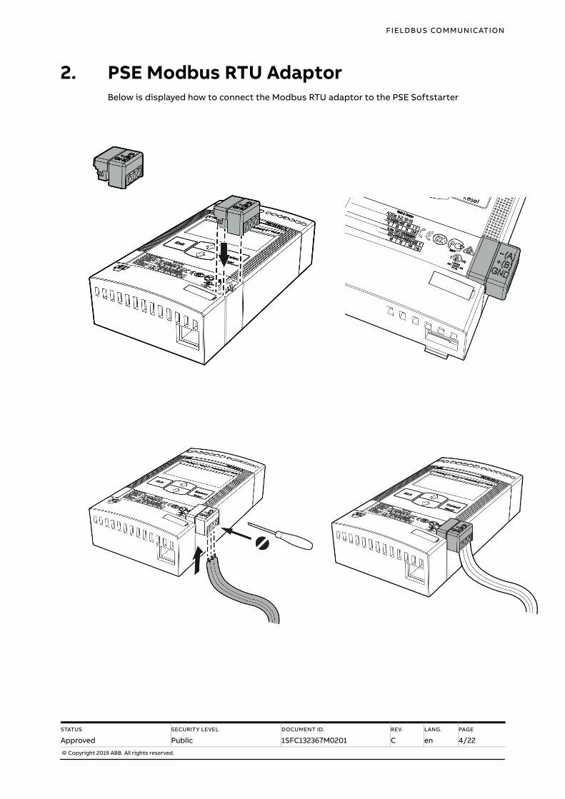
2. PSE Modbus RTU Adaptor Below is displayed how to connect the Modbus RTU adaptor to the PSE Softstarter
FIELDBUS COMMUNICATION
STATUS
Approved
SECURITY LEVEL
Public
DOCUMENT ID.
1SFC132367M0201
REV.
C
LANG.
en
PAGE
5/22
© Copyright 2019 ABB. All rights reserved.
3. PSE Data
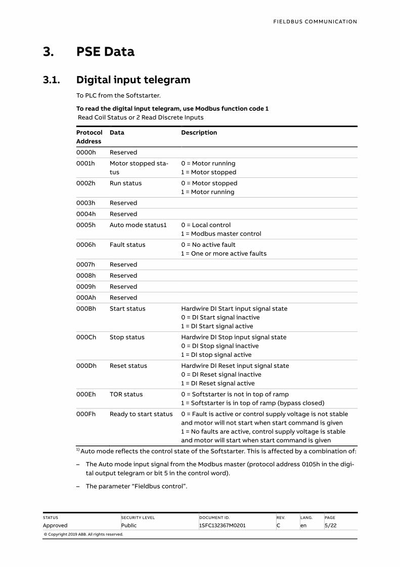
3.1. Digital input telegram
To PLC from the Softstarter.
To read the digital input telegram, use Modbus function code 1
Read Coil Status or 2 Read Discrete Inputs
Protocol
Address
Data Description
0000h Reserved
0001h Motor stopped sta-
tus
0 = Motor running
1 = Motor stopped
0002h Run status 0 = Motor stopped
1 = Motor running
0003h Reserved
0004h Reserved
0005h Auto mode status1 0 = Local control
1 = Modbus master control
0006h Fault status 0 = No active fault
1 = One or more active faults
0007h Reserved
0008h Reserved
0009h Reserved
000Ah Reserved
000Bh Start status Hardwire DI Start input signal state
0 = DI Start signal inactive
1 = DI Start signal active
000Ch Stop status Hardwire DI Stop input signal state
0 = DI Stop signal inactive
1 = DI stop signal active
000Dh Reset status Hardwire DI Reset input signal state
0 = DI Reset signal inactive
1 = DI Reset signal active
000Eh TOR status 0 = Softstarter is not in top of ramp
1 = Softstarter is in top of ramp (bypass closed)
000Fh Ready to start status 0 = Fault is active or control supply voltage is not stable
and motor will not start when start command is given
1 = No faults are active, control supply voltage is stable
and motor will start when start command is given
1) Auto mode reflects the control state of the Softstarter. This is affected by a combination of:
– The Auto mode input signal from the Modbus master (protocol address 0105h in the digi-
tal output telegram or bit 5 in the control word).
– The parameter “Fieldbus control”.
FIELDBUS COMMUNICATION
STATUS
Approved
SECURITY LEVEL
Public
DOCUMENT ID.
1SFC132367M0201
REV.
C
LANG.
en
PAGE
6/22
© Copyright 2019 ABB. All rights reserved.
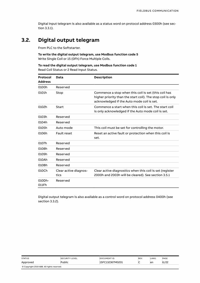
Digital input telegram is also available as a status word on protocol address 0300h (see sec-
tion 3.3.1).
3.2. Digital output telegram
From PLC to the Softstarter.
To write the digital output telegram, use Modbus function code 5
Write Single Coil or 15 (0Fh) Force Multiple Coils.
To read the digital output telegram, use Modbus function code 1
Read Coil Status or 2 Read Input Status.
Protocol
Address
Data Description
0100h Reserved
0101h Stop Commence a stop when this coil is set (this coil has
higher priority than the start coil). The stop coil is only
acknowledged if the Auto mode coil is set.
0102h Start Commence a start when this coil is set. The start coil
is only acknowledged if the Auto mode coil is set.
0103h Reserved
0104h Reserved
0105h Auto mode This coil must be set for controlling the motor.
0106h Fault reset Reset an active fault or protection when this coil is
set.
0107h Reserved
0108h Reserved
0109h Reserved
010Ah Reserved
010Bh Reserved
010Ch Clear active diagnos-
tics
Clear active diagnostics when this coil is set (register
2000h and 2003h will be cleared). See section 3.5.1
010Dh-
011Fh
Reserved
Digital output telegram is also available as a control word on protocol address 0400h (see
section 3.3.2).
FIELDBUS COMMUNICATION
STATUS
Approved
SECURITY LEVEL
Public
DOCUMENT ID.
1SFC132367M0201
REV.
C
LANG.
en
PAGE
7/22
© Copyright 2019 ABB. All rights reserved.
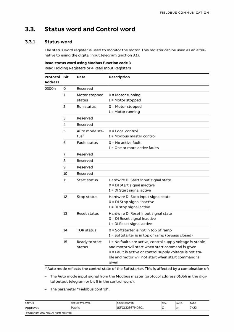
3.3. Status word and Control word
3.3.1. Status word
The status word register is used to monitor the motor. This register can be used as an alter-
native to using the digital input telegram (section 3.1).
Read status word using Modbus function code 3
Read Holding Registers or 4 Read Input Registers
Protocol
Address
Bit Data Description
0300h 0 Reserved
1 Motor stopped
status
0 = Motor running
1 = Motor stopped
2 Run status 0 = Motor stopped
1 = Motor running
3 Reserved
4 Reserved
5 Auto mode sta-
tus1
0 = Local control
1 = Modbus master control
6 Fault status 0 = No active fault
1 = One or more active faults
7 Reserved
8 Reserved
9 Reserved
10 Reserved
11 Start status Hardwire DI Start input signal state
0 = DI Start signal inactive
1 = DI Start signal active
12 Stop status Hardwire DI Stop input signal state
0 = DI Stop signal inactive
1 = DI stop signal active
13 Reset status Hardwire DI Reset input signal state
0 = DI Reset signal inactive
1 = DI Reset signal active
14 TOR status 0 = Softstarter is not in top of ramp
1 = Softstarter is in top of ramp (bypass closed)
15 Ready to start
status
1 = No faults are active, control supply voltage is stable
and motor will start when start command is given
0 = Fault is active or control supply voltage is not sta-
ble and motor will not start when start command is
given
1) Auto mode reflects the control state of the Softstarter. This is affected by a combination of:
– The Auto mode input signal from the Modbus master (protocol address 0105h in the digi-
tal output telegram or bit 5 in the control word).
– The parameter “Fieldbus control”.
FIELDBUS COMMUNICATION
STATUS
Approved
SECURITY LEVEL
Public
DOCUMENT ID.
1SFC132367M0201
REV.
C
LANG.
en
PAGE
8/22
© Copyright 2019 ABB. All rights reserved.
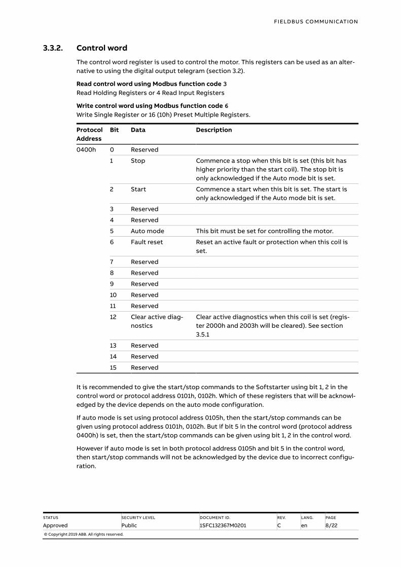
3.3.2. Control word
The control word register is used to control the motor. This registers can be used as an alter-
native to using the digital output telegram (section 3.2).
Read control word using Modbus function code 3
Read Holding Registers or 4 Read Input Registers
Write control word using Modbus function code 6
Write Single Register or 16 (10h) Preset Multiple Registers.
Protocol
Address
Bit Data Description
0400h 0 Reserved
1 Stop Commence a stop when this bit is set (this bit has
higher priority than the start coil). The stop bit is
only acknowledged if the Auto mode bit is set.
2 Start Commence a start when this bit is set. The start is
only acknowledged if the Auto mode bit is set.
3 Reserved
4 Reserved
5 Auto mode This bit must be set for controlling the motor.
6 Fault reset Reset an active fault or protection when this coil is
set.
7 Reserved
8 Reserved
9 Reserved
10 Reserved
11 Reserved
12 Clear active diag-
nostics
Clear active diagnostics when this coil is set (regis-
ter 2000h and 2003h will be cleared). See section
3.5.1
13 Reserved
14 Reserved
15 Reserved
It is recommended to give the start/stop commands to the Softstarter using bit 1, 2 in the
control word or protocol address 0101h, 0102h. Which of these registers that will be acknowl-
edged by the device depends on the auto mode configuration.
If auto mode is set using protocol address 0105h, then the start/stop commands can be
given using protocol address 0101h, 0102h. But if bit 5 in the control word (protocol address
0400h) is set, then the start/stop commands can be given using bit 1, 2 in the control word.
However if auto mode is set in both protocol address 0105h and bit 5 in the control word,
then start/stop commands will not be acknowledged by the device due to incorrect configu-
ration.

FIELDBUS COMMUNICATION
STATUS
Approved
SECURITY LEVEL
Public
DOCUMENT ID.
1SFC132367M0201
REV.
C
LANG.
en
PAGE
9/22
© Copyright 2019 ABB. All rights reserved.
3.4. Analog input telegram
To PLC from the Softstarter.
All analog input telegram data values are represented as 16-bit values.
To read the analog input telegram, use Modbus function code 3
Read Holding Registers or 4 Read Input Registers.
Protocol
Address
Data Representation
0200h Motor current in % of Ie (0%-800%) Value = 1 ⇒ 1%
0201h Thermal load in % of trip temperature (0%-100%) Value = 1 ⇒ 1%
0202h Phase current L1 Value = 1 ⇒ 1A
0203h Phase current L2 Value = 1 ⇒ 1A
0204h Phase current L3 Value = 1 ⇒ 1A
0205h Max phase current Value = 1 ⇒ 1A
0206h Measured frequency Value = 1 ⇒ 1Hz
0207h Measured power factor Value = 100 ⇒ 1
0208h Output voltage in % of line voltage Value = 1 ⇒ 1%
0209h Counted number of starts Value = 1 ⇒ 100
020Ah Run time in hours Value = 1 ⇒ 10h
020Bh Modbus failure register (the address from which
data could not be read from or written to)
Value = 1 ⇒ 1
020Ch Modbus toggle bit (value toggles at every read) Value = 1 ⇒ 1
3.5. Diagnostics
3.5.1. Diagnostic data
To PLC from the Softstarter.
To read the diagnostics data, use Modbus function code 3
Read Holding Registers or 4 Read Input Registers.
Protocol
Address
Bit Data Description
2000h 0 Reset possible on active
event
Current fault or protection can be reset
1 Software fault Internal fault
2 Shunt fault Current is flowing when it should not
3 By-pass open By-pass does not close
4 Softstarter overload Too high thyristor- or heat sink temperature
5 Phase loss No voltage in one or more phases on the
line side
6 Bad network quality Bad network quality on the line side
7 Current loss Current is not flowing when it should
FIELDBUS COMMUNICATION
STATUS
Approved
SECURITY LEVEL
Public
DOCUMENT ID.
1SFC132367M0201
REV.
C
LANG.
en
PAGE
10/22
© Copyright 2019 ABB. All rights reserved.
Protocol
Address
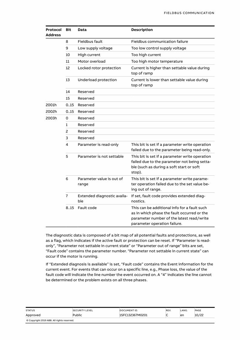
Bit Data Description
8 Fieldbus fault Fieldbus communication failure
9 Low supply voltage Too low control supply voltage
10 High current Too high current
11 Motor overload Too high motor temperature
12 Locked rotor protection Current is higher than settable value during
top of ramp
13 Underload protection Current is lower than settable value during
top of ramp
14 Reserved
15 Reserved
2001h 0..15 Reserved
2002h 0..15 Reserved
2003h 0 Reserved
1 Reserved
2 Reserved
3 Reserved
4 Parameter is read-only This bit is set if a parameter write operation
failed due to the parameter being read-only.
5 Parameter is not settable This bit is set if a parameter write operation
failed due to the parameter not being setta-
ble (such as during a soft start or soft
stop).
6 Parameter value is out of
range
This bit is set if a parameter write parame-
ter operation failed due to the set value be-
ing out of range.
7 Extended diagnostic availa-
ble
If set, fault code provides extended diag-
nostics.
8..15 Fault code This can be additional info for a fault such
as in which phase the fault occurred or the
parameter number of the latest read/write
parameter operation failure.
The diagnostic data is composed of a bit map of all potential faults and protections, as well
as a flag, which indicates if the active fault or protection can be reset. If “Parameter is read-
only”, “Parameter not settable in current state” or “Parameter out of range” bits are set,
“Fault code” contains the parameter number. “Parameter not settable in current state” can
occur if the motor is running.
If “Extended diagnosis is available” is set, “Fault code” contains the Event information for the
current event. For events that can occur on a specific line, e.g., Phase loss, the value of the
fault code will indicate the line number the event occurred on. A “4” indicates the line cannot
be determined or the problem exists on all three phases.
FIELDBUS COMMUNICATION
STATUS
Approved
SECURITY LEVEL
Public
DOCUMENT ID.
1SFC132367M0201
REV.
C
LANG.
en
PAGE
11/22
© Copyright 2019 ABB. All rights reserved.
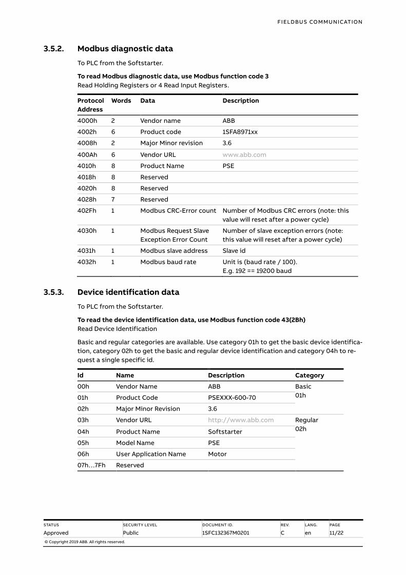
3.5.2. Modbus diagnostic data
To PLC from the Softstarter.
To read Modbus diagnostic data, use Modbus function code 3
Read Holding Registers or 4 Read Input Registers.
Protocol
Address
Words Data Description
4000h 2 Vendor name ABB
4002h 6 Product code 1SFA8971xx
4008h 2 Major Minor revision 3.6
400Ah 6 Vendor URL www.abb.com
4010h 8 Product Name PSE
4018h 8 Reserved
4020h 8 Reserved
4028h 7 Reserved
402Fh 1 Modbus CRC-Error count Number of Modbus CRC errors (note: this
value will reset after a power cycle)
4030h 1 Modbus Request Slave
Exception Error Count
Number of slave exception errors (note:
this value will reset after a power cycle)
4031h 1 Modbus slave address Slave id
4032h 1 Modbus baud rate Unit is (baud rate / 100).
E.g. 192 == 19200 baud
3.5.3. Device identification data
To PLC from the Softstarter.
To read the device identification data, use Modbus function code 43(2Bh)
Read Device Identification
Basic and regular categories are available. Use category 01h to get the basic device identifica-
tion, category 02h to get the basic and regular device identification and category 04h to re-
quest a single specific id.
Id Name Description Category
00h Vendor Name ABB Basic
01h 01h Product Code PSEXXX-600-70
02h Major Minor Revision 3.6
03h Vendor URL http://www.abb.com Regular
02h 04h Product Name Softstarter
05h Model Name PSE
06h User Application Name Motor
07h…7Fh Reserved
FIELDBUS COMMUNICATION
STATUS
Approved
SECURITY LEVEL
Public
DOCUMENT ID.
1SFC132367M0201
REV.
C
LANG.
en
PAGE
12/22
© Copyright 2019 ABB. All rights reserved.
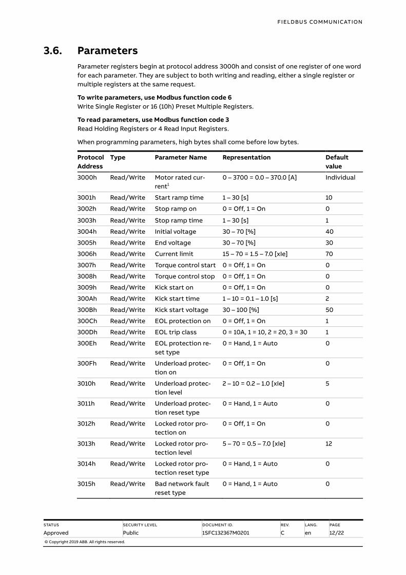
3.6. Parameters
Parameter registers begin at protocol address 3000h and consist of one register of one word
for each parameter. They are subject to both writing and reading, either a single register or
multiple registers at the same request.
To write parameters, use Modbus function code 6
Write Single Register or 16 (10h) Preset Multiple Registers.
To read parameters, use Modbus function code 3
Read Holding Registers or 4 Read Input Registers.
When programming parameters, high bytes shall come before low bytes.
Protocol
Address
Type Parameter Name Representation Default
value
3000h Read/Write Motor rated cur-
rent1
0 – 3700 = 0.0 – 370.0 [A] Individual
3001h Read/Write Start ramp time 1 – 30 [s] 10
3002h Read/Write Stop ramp on 0 = Off, 1 = On 0
3003h Read/Write Stop ramp time 1 – 30 [s] 1
3004h Read/Write Initial voltage 30 – 70 [%] 40
3005h Read/Write End voltage 30 – 70 [%] 30
3006h Read/Write Current limit 15 – 70 = 1.5 – 7.0 [xIe] 70
3007h Read/Write Torque control start 0 = Off, 1 = On 0
3008h Read/Write Torque control stop 0 = Off, 1 = On 0
3009h Read/Write Kick start on 0 = Off, 1 = On 0
300Ah Read/Write Kick start time 1 – 10 = 0.1 – 1.0 [s] 2
300Bh Read/Write Kick start voltage 30 – 100 [%] 50
300Ch Read/Write EOL protection on 0 = Off, 1 = On 1
300Dh Read/Write EOL trip class 0 = 10A, 1 = 10, 2 = 20, 3 = 30 1
300Eh Read/Write EOL protection re-
set type
0 = Hand, 1 = Auto 0
300Fh Read/Write Underload protec-
tion on
0 = Off, 1 = On 0
3010h Read/Write Underload protec-
tion level
2 – 10 = 0.2 – 1.0 [xIe] 5
3011h Read/Write Underload protec-
tion reset type
0 = Hand, 1 = Auto 0
3012h Read/Write Locked rotor pro-
tection on
0 = Off, 1 = On 0
3013h Read/Write Locked rotor pro-
tection level
5 – 70 = 0.5 – 7.0 [xIe] 12
3014h Read/Write Locked rotor pro-
tection reset type
0 = Hand, 1 = Auto 0
3015h Read/Write Bad network fault
reset type
0 = Hand, 1 = Auto 0
FIELDBUS COMMUNICATION
STATUS
Approved
SECURITY LEVEL
Public
DOCUMENT ID.
1SFC132367M0201
REV.
C
LANG.
en
PAGE
13/22
© Copyright 2019 ABB. All rights reserved.
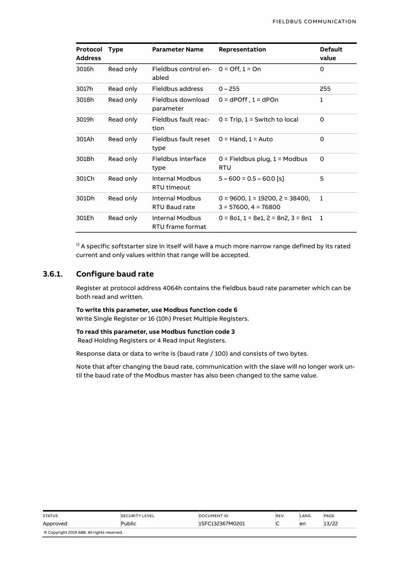
Protocol
Address
Type Parameter Name Representation Default
value
3016h Read only Fieldbus control en-
abled
0 = Off, 1 = On 0
3017h Read only Fieldbus address 0 – 255 255
3018h Read only Fieldbus download
parameter
0 = dPOff , 1 = dPOn 1
3019h Read only Fieldbus fault reac-
tion
0 = Trip, 1 = Switch to local 0
301Ah Read only Fieldbus fault reset
type
0 = Hand, 1 = Auto 0
301Bh Read only Fieldbus interface
type
0 = Fieldbus plug, 1 = Modbus
RTU
0
301Ch Read only Internal Modbus
RTU timeout
5 – 600 = 0.5 – 60.0 [s] 5
301Dh Read only Internal Modbus
RTU Baud rate
0 = 9600, 1 = 19200, 2 = 38400,
3 = 57600, 4 = 76800
1
301Eh Read only Internal Modbus
RTU frame format
0 = 8o1, 1 = 8e1, 2 = 8n2, 3 = 8n1 1
1) A specific softstarter size in itself will have a much more narrow range defined by its rated
current and only values within that range will be accepted.
3.6.1. Configure baud rate
Register at protocol address 4064h contains the fieldbus baud rate parameter which can be
both read and written.
To write this parameter, use Modbus function code 6
Write Single Register or 16 (10h) Preset Multiple Registers.
To read this parameter, use Modbus function code 3
Read Holding Registers or 4 Read Input Registers.
Response data or data to write is (baud rate / 100) and consists of two bytes.
Note that after changing the baud rate, communication with the slave will no longer work un-
til the baud rate of the Modbus master has also been changed to the same value.
FIELDBUS COMMUNICATION
STATUS
Approved
SECURITY LEVEL
Public
DOCUMENT ID.
1SFC132367M0201
REV.
C
LANG.
en
PAGE
14/22
© Copyright 2019 ABB. All rights reserved.
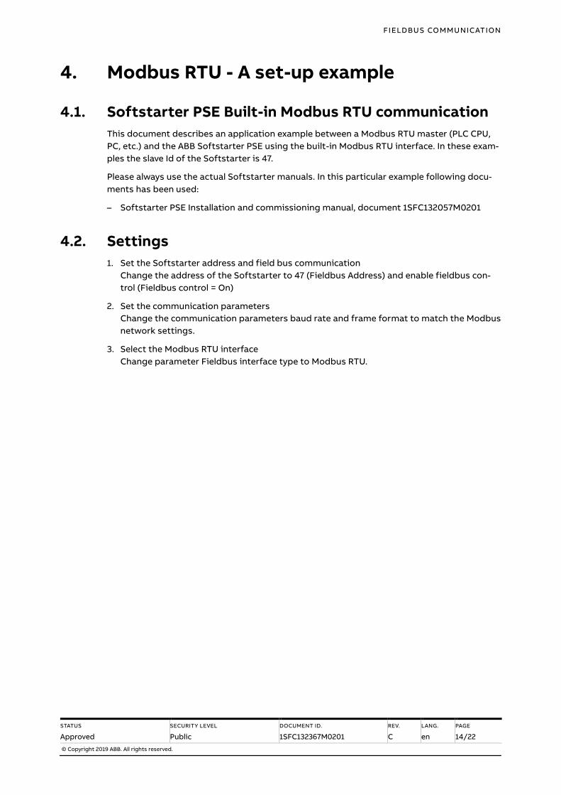
4. Modbus RTU - A set-up example
4.1. Softstarter PSE Built-in Modbus RTU communication
This document describes an application example between a Modbus RTU master (PLC CPU,
PC, etc.) and the ABB Softstarter PSE using the built-in Modbus RTU interface. In these exam-
ples the slave Id of the Softstarter is 47.
Please always use the actual Softstarter manuals. In this particular example following docu-
ments has been used:
– Softstarter PSE Installation and commissioning manual, document 1SFC132057M0201
4.2. Settings
1. Set the Softstarter address and field bus communication
Change the address of the Softstarter to 47 (Fieldbus Address) and enable fieldbus con-
trol (Fieldbus control = On)
2. Set the communication parameters
Change the communication parameters baud rate and frame format to match the Modbus
network settings.
3. Select the Modbus RTU interface
Change parameter Fieldbus interface type to Modbus RTU.
FIELDBUS COMMUNICATION
STATUS
Approved
SECURITY LEVEL
Public
DOCUMENT ID.
1SFC132367M0201
REV.
C
LANG.
en
PAGE
15/22
© Copyright 2019 ABB. All rights reserved.
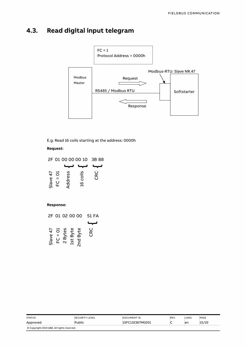
4.3. Read digital input telegram
E.g: Read 16 coils starting at the address: 0000h
Request:
2F 01 00 00 00 10 3B 88 { { {
Sla
ve
47
FC
= 0
1
Ad
dre
ss
16 c
oil
s
CR
C
Response:
2F 01 02 00 00 51 FA {
Sla
ve
47
FC
= 0
1
2 B
yte
s
1st
Byt
e
2n
d B
yte
CR
C
Request
Response
RS485 / Modbus RTU
Modbus-RTU: Slave NR.47
Modbus
Master
Softstarter
FC = 1
Protocol Address = 0000h

FIELDBUS COMMUNICATION
STATUS
Approved
SECURITY LEVEL
Public
DOCUMENT ID.
1SFC132367M0201
REV.
C
LANG.
en
PAGE
16/22
© Copyright 2019 ABB. All rights reserved.
4.4. Write digital output telegram
E.g: Write 16 coils starting at address 0100h
Request:
2F 0F 01 00 00 10 02 00 00 27 41 { { { {
Slav
e 4
7
FC =
15
Ad
dre
ss
16
co
ils
2 b
ytes
Ou
tpu
t
CR
C
Response:
2F 0F 01 00 00 10 53 B5 { { {
Slav
e 4
7
FC =
15
Ad
dre
ss
16
co
ils
CR
C
Request
Response
RS485 / Modbus RTU
Modbus-RTU: Slave NR.47
Modbus
Master
Softstarter
FC = 15
Protocol Address = 0100h
FIELDBUS COMMUNICATION
STATUS
Approved
SECURITY LEVEL
Public
DOCUMENT ID.
1SFC132367M0201
REV.
C
LANG.
en
PAGE
17/22
© Copyright 2019 ABB. All rights reserved.
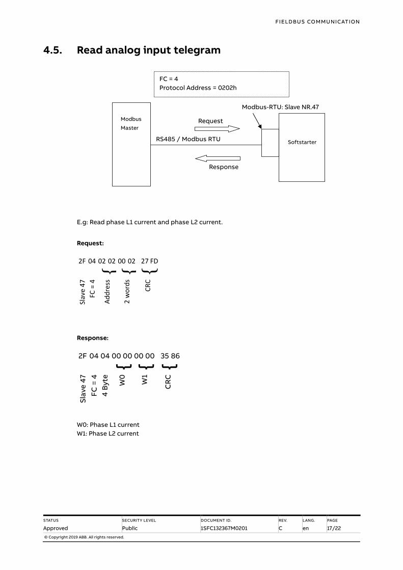
4.5. Read analog input telegram
E.g: Read phase L1 current and phase L2 current.
Request:
2F 04 02 02 00 02 27 FD { { {
Slav
e 4
7
FC =
4
Ad
dre
ss
2 w
ord
s
CR
C
Response:
2F 04 04 00 00 00 00 35 86 { { {
Sla
ve
47
FC
= 4
4 B
yte
W0
W1
CR
C
W0: Phase L1 current
W1: Phase L2 current
Request
Response
RS485 / Modbus RTU
Modbus-RTU: Slave NR.47
Modbus
Master
Softstarter
FC = 4
Protocol Address = 0202h
FIELDBUS COMMUNICATION
STATUS
Approved
SECURITY LEVEL
Public
DOCUMENT ID.
1SFC132367M0201
REV.
C
LANG.
en
PAGE
18/22
© Copyright 2019 ABB. All rights reserved.
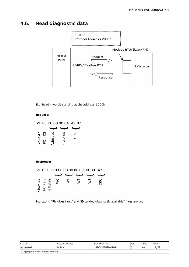
4.6. Read diagnostic data
E.g: Read 4 words starting at the address: 2000h
Request:
2F 03 20 00 00 04 49 87 { { {
Sla
ve
47
FC
= 0
3
Ad
dre
ss
4 w
ord
s
CR
C
Response:
2F 03 08 01 00 00 00 00 00 00 80 CA 93 { { { { {
Sla
ve
47
FC
= 0
3
8 B
yte
s
W0
W1
W2
W3
CR
C
Indicating “Fieldbus fault” and “Extended diagnostic available” flags are set.
Request
Response
RS485 / Modbus RTU
Modbus-RTU: Slave NR.47
Modbus
Master
Softstarter
FC = 03
Protocol Address = 2000h
FIELDBUS COMMUNICATION
STATUS
Approved
SECURITY LEVEL
Public
DOCUMENT ID.
1SFC132367M0201
REV.
C
LANG.
en
PAGE
19/22
© Copyright 2019 ABB. All rights reserved.
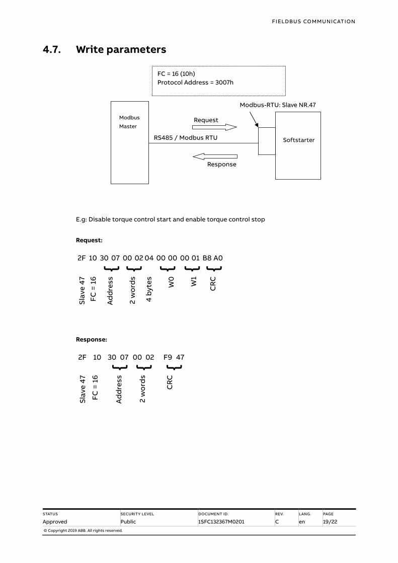
4.7. Write parameters
E.g: Disable torque control start and enable torque control stop
Request:
2F 10 30 07 00 02 04 00 00 00 01 B8 A0 { { { { {
Sla
ve
47
FC
= 1
6
Ad
dre
ss
2 w
ord
s
4 b
yte
s
W0
W
1
CR
C
Response:
2F 10 30 07 00 02 F9 47 { { {
Sla
ve
47
FC
= 1
6
Ad
dre
ss
2 w
ord
s
CR
C
Request
Response
RS485 / Modbus RTU
Modbus-RTU: Slave NR.47
Modbus
Master
Softstarter
FC = 16 (10h)
Protocol Address = 3007h
FIELDBUS COMMUNICATION
STATUS
Approved
SECURITY LEVEL
Public
DOCUMENT ID.
1SFC132367M0201
REV.
C
LANG.
en
PAGE
20/22
© Copyright 2019 ABB. All rights reserved.
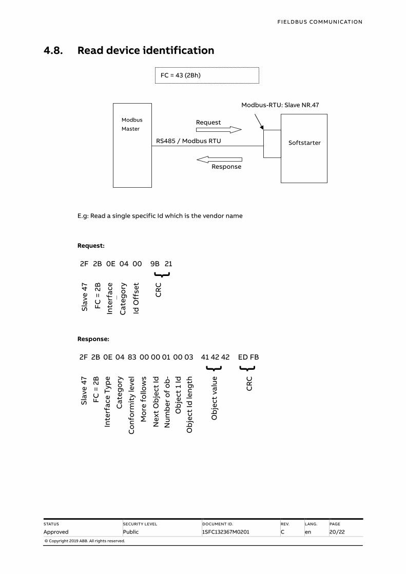
4.8. Read device identification
E.g: Read a single specific Id which is the vendor name
Request:
2F 2B 0E 04 00 9B 21 {
Sla
ve
47
FC
= 2
B
Inte
rfa
ce
Ty
pe
C
ate
go
ry
Id O
ffs
et
CR
C
Response:
2F 2B 0E 04 83 00 00 01 00 03 41 42 42 ED FB { {
Sla
ve
47
FC
= 2
B
Inte
rfa
ce
Ty
pe
Ca
teg
ory
Co
nfo
rmit
y le
ve
l
Mo
re f
ollo
ws
Ne
xt
Ob
jec
t Id
Nu
mb
er
of
ob
-
jec
ts
Ob
jec
t 1
Id
Ob
jec
t Id
len
gth
Ob
jec
t va
lue
CR
C
Request
Response
RS485 / Modbus RTU
Modbus-RTU: Slave NR.47
Modbus
Master
Softstarter
FC = 43 (2Bh)
FIELDBUS COMMUNICATION
STATUS
Approved
SECURITY LEVEL
Public
DOCUMENT ID.
1SFC132367M0201
REV.
C
LANG.
en
PAGE
21/22
© Copyright 2019 ABB. All rights reserved.
5. Troubleshooting
5.1. Modbus slave does not respond to requests
RS485
– Are the termination resistors placed at the end of the line?
– Only 2 termination resistors in one segment?
– Are 2 termination resistors placed at each bus segment?
– Are bias resistors connected in each bus segment?
– Is the line polarity correct? Are the lines by accident swapped?
– Never place any termination resistors on a drop cable.
– Is the maximum line length exceeded?
Modbus Parameters
– Check that fieldbus interface type parameter is set to Internal Modbus-RTU (Int on dis-
play).
– Check that you are using the correct Modbus address, baud rate and frame format.
– Note that the slave will not respond to broadcasts (requests to address 0), only act upon
them.
Modbus slave
– Has the device a unique Modbus address?
– Is the function code supported by the device?
– Has the request a valid address?
– Has the request a valid quantity of coils, inputs, registers?
– Is the power supply turned on?
Modbus master
– Is the Modbus master in RTU mode?
– Is the request to response timeout correct?
– Is the Modbus silent interval between two telegrams > 3.5 character times?
– Notice that the slave device will not give any response when it is addressed with a broad-
cast (slave address = 0).
– Check if PLC is in run mode.
5.2. PSE trips on fieldbus fault (EF40)
– The purpose of the fieldbus fault function is to detect any communication problems be-
tween the Modbus master and the Softstarter.
– Fieldbus fault will be enabled if the Fieldbus control parameter is set to On and Operation
when fault parameter is set to “trIP”. In case the Operation when fault parameter is set as
“LocC”, there will be a switch to local “hardwire” control.
FIELDBUS COMMUNICATION
STATUS
Approved
SECURITY LEVEL
Public
DOCUMENT ID.
1SFC132367M0201
REV.
C
LANG.
en
PAGE
22/22
© Copyright 2019 ABB. All rights reserved.
– If the Modbus master has not written any data to the PSE softstarter or read any data
from the PSE softstarter for more than the configured timeout time, there will be a trip on
fieldbus fault (EF40). This fieldbus fault communication timeout parameter can have a
value between from 0.5 to 60 seconds and can be set from the HMI or with the
SoftstarterCare™ Service Engineer Tool PC program via USB. If there has been a trip on
fieldbus fault for some reason, the communication has to afterwards be continuously sta-
ble for 10s before the PSE softstarter accepts commands from the Modbus master and
when it is possible to reset the fault.
– If the fault code is EF41, this means a parity error has occurred and in most cases this is
due to the parity being incorrectly configured. Check the Modbus frame format parameter
and the Modbus master’s parity configuration.
5.3. Motor does not start
– If fieldbus fault reaction is set to “switch to local” control and fieldbus communication is
lost and/or timeout is reached, the Softstarter can only be controlled with hard-wire sig-
nals. When communication is re-established, there is a 10 second delay before fieldbus
control is possible.
– Check if the fieldbus control parameter is set to ON.
– Make sure the auto mode is enabled in order to control the motor with Modbus. Either the
data value in protocol address 0105h or bit 5 in the control word (protocol address 0400h)
shall be set.
– Check if the stop coil/bit is set since it has higher priority than the start coil/bit.
– Motor will not start if there is an active fault (check the ready to start coil/bit).
5.4. Parameter write does not work
– Check if the parameter download parameter is enabled (set to dPon).
– Check if the parameter is read-only.
– Check if the value to be written is correctly scaled (see the representation column in sec-
tion 3.6).
– Check if the value to be written is out of range.
– Parameter write operation will not work during a soft start or soft stop. It will only work in
the standby state and top of ramp state.
– Check bits 4-15 in protocol address 2003h for diagnostic information related to the latest
parameter write operation failure (see section 3.5.1).
6. Contact us For more information, please contact
your local ABB representative or visit
https://new.abb.com/low-voltage/products/softstarters-new