Embed Size (px)
Citation preview

OPERATION AND MAINTENANCEINSTRUCTION / MANUAL
Fieldbus Relay and Dry Contact Input
F R I 3 0 2 M E

web: www.smar.com/contactus.asp
www.smar.com
Specifications and information are subject to change without notice.
Up-to-date address information is available on our website.
smar

Introduction
III
INTRODUCTION The FRI302 is a fieldbus device that has two built-in relays making integration of Fieldbus to conventional devices such as solenoids, on/off valves, electrical actuators, motors, pumps, starters, etc. The FRI302 also has two dry contact inputs. The FRI302 Fieldbus Relay and dry contact Input can be located in the field, mounted close to the conventional devices without the need to run the conventional wiring to the control room. The FRI302 is an integral part of SYSTEM302 but also integrates into other systems that support FOUNDATION™ Fieldbus. The FRI302 allows that conventional discrete outputs be available, in order to make the control strategy configuration easy. Using standard FOUNDATION™ Fieldbus Function blocks, these outputs appear as regular Fieldbus devices, thus making the system homogenous. Control loops are implemented consistently. An extensive function block library enables the FRI302 to perform logic control functions in the field integrating it to its discrete outputs. Instantiated function blocks provide great flexibility in the control strategy. The FRI302 is fully configured by Syscon software in SYSTEM302 or any other FOUNDATION™ Fieldbus configuration tool. “Link master” capability allows the FRI302 to work as a backup LAS for greater availability of network communications. The FRI302 may be installed close to the final elements, thereby eliminating long wire runs, associated marshalling panels and cable trays for the conventional output. With subsequent savings further reducing overall system costs. The use of FRI302 makes it possible to distribute outputs at various locations in the field and connect them via the H1 Fieldbus. Get the best result of the FRI302 by carefully reading these instructions.

FRI302 - Operation & Maintenance Instruction Manual.
IV
WARNING
This Manual is compatible with version 3.XX, where 3 denotes software version and XX software release. The indication 3.XX means that this manual is compatible with any release of software version 3.
Waiver of responsibility The contents of this manual abides by the hardware and software used on the current equipmentversion. Eventually there may occur divergencies between this manual and the equipment. Theinformation from this document are periodically reviewed and the necessary or identified corrections will be included in the following editions. Suggestions for their improvement are welcome. Warning For more objectivity and clarity, this manual does not contain all the detailed information on the product and, in addition, it does not cover every possible mounting, operation or maintenancecases. Before installing and utilizing the equipment, check if the model of the acquired equipment complieswith the technical requirements for the application. This checking is the user’s responsibility. If the user needs more information, or on the event of specific problems not specified or treated inthis manual, the information should be sought from Smar. Furthermore, the user recognizes that thecontents of this manual by no means modify past or present agreements, confirmation or judicialrelationship, in whole or in part. All of Smar’s obligation result from the purchasing agreement signed between the parties, whichincludes the complete and sole valid warranty term. Contractual clauses related to the warranty arenot limited nor extended by virtue of the technical information contained in this manual. Only qualified personnel are allowed to participate in the activities of mounting, electrical connection, startup and maintenance of the equipment. Qualified personnel are understood to be the personsfamiliar with the mounting, electrical connection, startup and operation of the equipment or othersimilar apparatus that are technically fit for their work. Smar provides specific training to instruct and qualify such professionals. However, each country must comply with the local safety procedures,legal provisions and regulations for the mounting and operation of electrical installations, as well aswith the laws and regulations on classified areas, such as intrinsic safety, explosion proof, increasedsafety and instrumented safety systems, among others. The user is responsible for the incorrect or inadequate handling of equipments run with pneumaticor hydraulic pressure or, still, subject to corrosive, aggressive or combustible products, since theirutilization may cause severe bodily harm and/or material damages. The field equipment referred to in this manual, when acquired for classified or hazardous areas, has its certification void when having its parts replaced or interchanged without functional and approvaltests by Smar or any of Smar authorized dealers, which are the competent companies for certifyingthat the equipment in its entirety meets the applicable standards and regulations. The same is true when converting the equipment of a communication protocol to another. In this case, it is necessarysending the equipment to Smar or any of its authorized dealer. Moreover, the certificates aredifferent and the user is responsible for their correct use. Always respect the instructions provided in the Manual. Smar is not responsible for any lossesand/or damages resulting from the inadequate use of its equipments. It is the user’s responsibility to know and apply the safety practices in his country.

Index
V
TABLE OF CONTENTS
SECTION 1 - INSTALLATION ......................................................................................................................... 1.1 GENERAL ................................................................................................................................................... 1.1 MOUNTING ................................................................................................................................................. 1.1 ELECTRIC WIRING .................................................................................................................................... 1.1 TOPOLOGY AND NETWORK CONFIGURATION ..................................................................................... 1.7 GENERAL SYSTEM ................................................................................................................................... 1.9
SECTION 2 - OPERATION .............................................................................................................................. 2.1
FUNCTIONAL DESCRIPTION – ELECTRONICS ...................................................................................... 2.1 (CPU) CENTRAL PROCESSING UNIT, RAM AND FLASH ....................................................................... 2.1
SECTION 3 - CONFIGURATION ..................................................................................................................... 3.1
FUNCTIONAL DIAGRAM ........................................................................................................................... 3.1
OUTPUT TRANSDUCER BLOCKS ............................................................................................................ 3.2
CONNECTING PHYSICAL SIGNALS TO DIGITAL OUTPUT BLOCK ...................................................... 3.3
CONNECTING PHYSICAL SIGNALS TO PID STEP ................................................................................. 3.3
EXAMPLES OF APPLICATIONS ................................................................................................................ 3.4
FUNCTION BLOCK TYPE AVAILABILITY AND INITIAL BLOCK SET ...................................................... 3.5
SECTION 4 -MAINTENANCE PROCEDURES ............................................................................................... 4.1 GENERAL ................................................................................................................................................... 4.1
DISASSEMBLY PROCEDURE ................................................................................................................... 4.1
REASSEMBLY PROCEDURE .................................................................................................................... 4.2
SECTION 5 - TECHNICAL SPECIFICATIONS ............................................................................................... 5.1 GENERAL ................................................................................................................................................... 5.1
FRI302 OUTPUT RELAYS ......................................................................................................................... 5.1
TECHNICAL SPECIFICATIONS FOR NORMALLY CLOSED RELAYS .................................................... 5.2
TECHNICAL SPECIFICATIONS FOR NORMALLY OPENED RELAYS .................................................... 5.2
TECHNICAL SPECIFICATIONS FOR DRY CONTACT INPUT ................................................................. 5.3
ORDERING CODE ...................................................................................................................................... 5.3
APPENDIX A - SRF – SERVICE REQUEST FORM ...................................................................................... A.1
RETURNING MATERIALS ........................................................................................................................ A.2
Installation Flowchart
VI
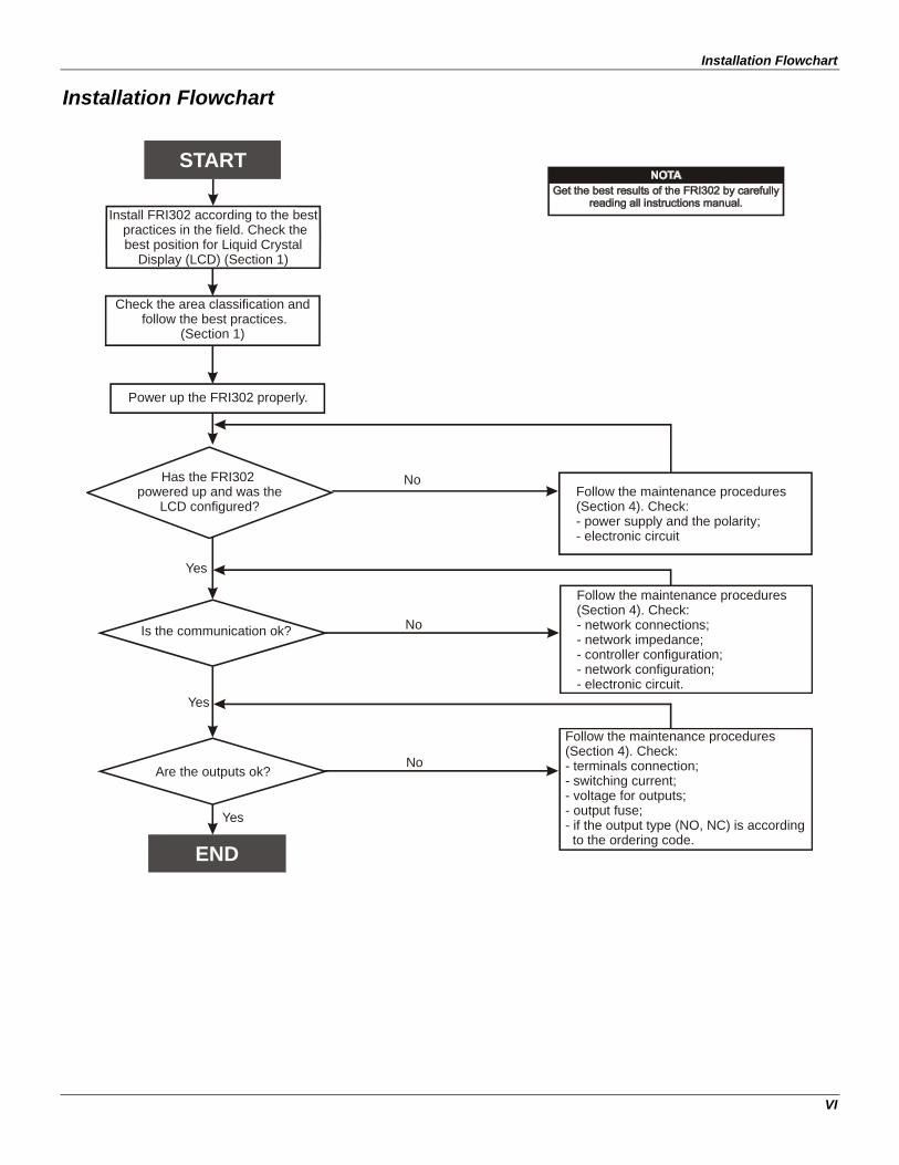
Installation Flowchart
Install FRI302 according to the best practices in the field. Check the best position for Liquid Crystal
Display (LCD) (Section 1)
Check the area classification and follow the best practices.
(Section 1)
START
END
Yes
No
No
No
Has the FRI302 powered up and was the
LCD configured?
Is the communication ok?
Are the outputs ok?
Follow the maintenance procedures (Section 4). Check:- power supply and the polarity;- electronic circuit
Follow the maintenance procedures (Section 4). Check:- network connections;- network impedance;- controller configuration;- network configuration;- electronic circuit.
Follow the maintenance procedures (Section 4). Check:- terminals connection;- switching current;- voltage for outputs;- output fuse;- if the output type (NO, NC) is according to the ordering code.
Power up the FRI302 properly.
Yes
Yes

Section 1
1.1
INSTALLATION General
The overall reliability of actuation and control depends on several variables. Although the Fieldbus Relay and dry contact Input has an outstanding performance, proper installation is essential in order to maximize its performance. Among all factors, which may affect the accuracy, the environmental conditions are the most difficult to control. There are, however, ways of reducing the effects of temperature, humidity and vibration. Locating the Fieldbus Relay and dry contact Input in areas protected from extreme environmental changes can improve its performance. In warm environments, the Fieldbus Relay and dry contact Input should be installed to avoid, as much as possible, direct exposure to the sun. Installation close to lines and vessels subjected to high temperatures also should be avoided. The use of sunshades or heat shields to protect the Fieldbus Relay and dry contact Input from external heat sources should be considered, when necessary.
Humidity can be fatal to electronic circuits. A humidity proof coating protects the electronic circuit, but frequent exposures to humidity may affect the protection provided. It is also important to keep the covers tightened in place. Every time they are removed, the threads are exposed to corrosion, since painting cannot protect these parts. Code-approved sealing methods on conduit entering the converter should be employed. For details of mounting, please, refer to Figure 1.1.
Mounting
Using the bracket, the mounting may be done in several positions, as shown on Figure 1.1 - Dimensional Drawing and Mounting Positions. For better visibility, the digital indicator may be rotated in steps of 90° (See Section 4 – Maintenance Procedures).
PLUG
195.
5
95
(4.92)
(3.27)
96.6
(3.8
)
(Ø3
.27)
Ø83
83
PLUG
DN50
PIPE 2"
114.6
(4.51)
(3.74)
(7.7
0)
95
14.7
68
(2.68)
(0.58)
(3.74)
87.6
(3.45)
125ALLOW 150 MM MINIMUM FOR LOCALZERO AND SPAN ADJUSTMENT WITH MAGNETIC TOOL.
COMMUNICATIONS TERMINAL
MOUNTING BRACKET
CONDUITCONNECTION
WALL ORPANELMOUNTING
FOR WALL MOUNTING2 EXPANSION ANCHOR - 2 HEXAGON SCREW -
S8 3/16”X70
2 BOLT AND NUTS - 1/4”X30NOT INCLUDED
FOR PANEL MOUNTING
Figure 1.1 - Dimensional Drawing and Mounting Positions

FRI302 – Operation and Maintenance Instruction Manual
1.2
Electric Wiring Access the wiring block by removing the Electrical Connection Cover. This cover can be locked closed by the cover locking screw (See Figure 1.2 - Cover Locking). To release the cover, rotate the locking screw clockwise. Cable access to wiring connections is obtained by one of the two conduit outlets. Conduit threads should be sealed by means of code-approved sealing methods. The unused outlet port should be plugged accordingly.
Figure 1.2 - Cover Locking
The wiring block has screws, on which fork or ring type terminals can be fastened. See Figure 1.3 – Terminal Block.
FIELDBUS
IN1IN2
RELAY 2RELAY 1
CHANNEL
GROUNDTERMINALS
Figure 1.3 - Terminal Block
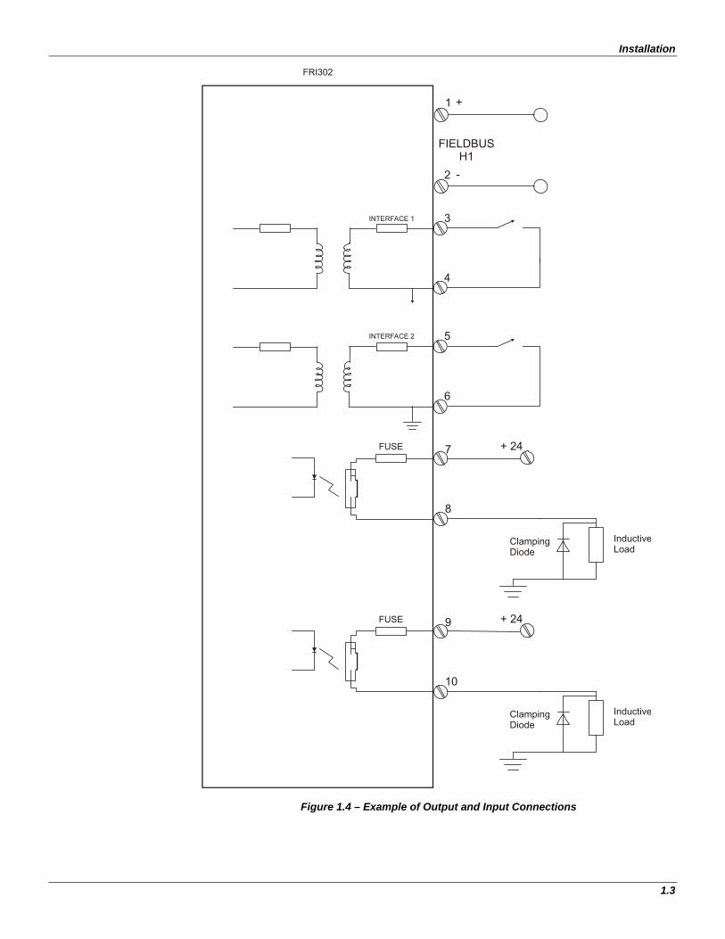
For convenience there are three ground terminals: one inside the cover and two externals, located close to the conduit entries. The unused port should be plugged accordingly. In Figure 1.4 you can see an example of output connections.
COVERLOCKINGSCREW
Installation
1.3
1
FIELDBUSH1
2
FRI302
INTERFACE 2
INTERFACE 1 3
4
5
6
+ 24FUSE 7
8
InductiveLoad
ClampingDiode
+ 24FUSE 9
10
InductiveLoad
ClampingDiode
+
-
Figure 1.4 – Example of Output and Input Connections

FRI302 – Operation and Maintenance Instruction Manual
1.4
The FRI302 is a bus-powered device. The FRI302 uses the 31.25 kbit/s voltage mode option for the physical signaling. Various types of Fieldbus devices may be connected on the same bus being bus-powered or non-bus-powered. When bus-powered, the devices must use the same signaling. Up to 16 devices can be connected in parallel along the same pair of wires. In hazardous areas, the number of devices may be limited by intrinsically safe restrictions. The FRI302 is protected against reverse polarity, and can withstand ±35 VDC without damage.
NOTE
For a DC connection it is recommended to use a protection diode and for an AC connection it is recommended to use a snubber, mainly for inductive loads.
Surge Suppression Transient EMI (electric noise) can be generated during the commutation of every inductive electric load. In many cases, the noise interferes directly on the origin of the commutation command and until may damage electronic components. Those transient peaks have a time of ascent very fast, generating a high induced tension where the automation wiring system works as the signal transmitter and receiver due to their capacitance.
VL = L di/dt
Off On
VL
Off
time
KV
VL
SW
LDC
Figure1.5 – Reverse Voltage Peak Some alternatives may avoid this interference, like optical couplers, Zero Crossing Switching, indirect startups that prevent the arrival of the noise to the command, but the noise generated by the commuted device continues existing and many times it is induced in the wiring system, reaching other automation electronic points, causing intermittent defects in the system. Therefore, those ways of treating the noise are not effective. It should be eliminated exactly in the noise source, in other words, in order to obtain a filter with better performance, it should be mounted the closest possible to the commuted load.
Installation
1.5
Relay ModuleL D
AC/DCRelay Module
Relay ModuleAC/DC
L
LR
C
R
C
RC Network
Transil / MOV
DC
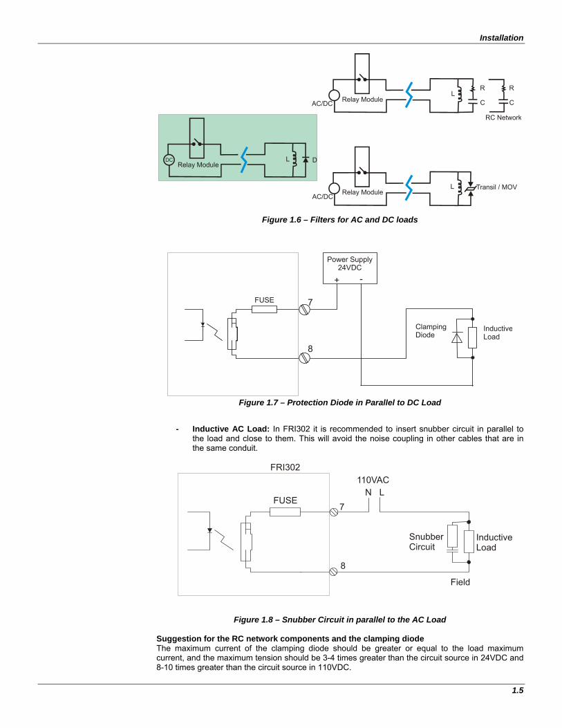
Figure 1.6 – Filters for AC and DC loads
FUSE 7
8
Power Supply24VDC
+ -
InductiveLoad
ClampingDiode
Figure 1.7 – Protection Diode in Parallel to DC Load
- Inductive AC Load: In FRI302 it is recommended to insert snubber circuit in parallel to the load and close to them. This will avoid the noise coupling in other cables that are in the same conduit.
InductiveLoad
SnubberCircuit
Field
FRI302
N L110VAC
FUSE7
8
Figure 1.8 – Snubber Circuit in parallel to the AC Load Suggestion for the RC network components and the clamping diode The maximum current of the clamping diode should be greater or equal to the load maximum current, and the maximum tension should be 3-4 times greater than the circuit source in 24VDC and 8-10 times greater than the circuit source in 110VDC.
FRI302 – Operation and Maintenance Instruction Manual
1.6
The RC circuit (AC) capacitor should have a tension 2-3 times greater than the power supply voltage. Recommended values:
Load Inductance Capacitor
25-70mH 0.50µF
70-180mH 0.250µF
180mH - 10H 0.10µF
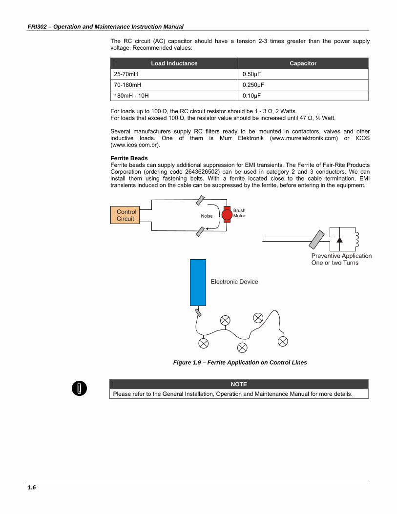
For loads up to 100 Ω, the RC circuit resistor should be 1 - 3 Ω, 2 Watts. For loads that exceed 100 Ω, the resistor value should be increased until 47 Ω, ½ Watt. Several manufacturers supply RC filters ready to be mounted in contactors, valves and other inductive loads. One of them is Murr Elektronik (www.murrelektronik.com) or ICOS (www.icos.com.br). Ferrite Beads Ferrite beads can supply additional suppression for EMI transients. The Ferrite of Fair-Rite Products Corporation (ordering code 2643626502) can be used in category 2 and 3 conductors. We can install them using fastening belts. With a ferrite located close to the cable termination, EMI transients induced on the cable can be suppressed by the ferrite, before entering in the equipment.
ControlCircuit Noise
BrushMotor
Electronic Device
Preventive ApplicationOne or two Turns
Figure 1.9 – Ferrite Application on Control Lines
NOTE
Please refer to the General Installation, Operation and Maintenance Manual for more details.
Installation
1.7
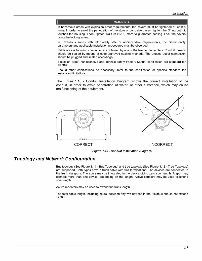
WARNING In hazardous areas with explosion proof requirements, the covers must be tightened at least 8 turns. In order to avoid the penetration of moisture or corrosive gases, tighten the O’ring until it touches the housing. Then, tighten 1/3 turn (120) more to guarantee sealing. Lock the covers using the locking screw.
In hazardous zones with intrinsically safe or nonincendive requirements, the circuit entity parameters and applicable installation procedures must be observed.
Cable access to wiring connections is obtained by one of the two conduit outlets. Conduit threads should be sealed by means of code-approved sealing methods. The unused outlet connection should be plugged and sealed accordingly.
Explosion proof, nonincendive and intrinsic safety Factory Mutual certification are standard for FRI302. Should other certifications be necessary, refer to the certification or specific standard for installation limitations.
The Figure 1.10 - Conduit Installation Diagram, shows the correct installation of the conduit, in order to avoid penetration of water, or other substance, which may cause malfunctioning of the equipment.
CORRECT
WIRES
INCORRECT
Figure 1.10 - Conduit Installation Diagram.
Topology and Network Configuration Bus topology (See Figure 1.11 - Bus Topology) and tree topology (See Figure 1.12 - Tree Topology) are supported. Both types have a trunk cable with two terminations. The devices are connected to the trunk via spurs. The spurs may be integrated in the device giving zero spur length. A spur may connect more than one device, depending on the length. Active couplers may be used to extend spur length. Active repeaters may be used to extend the trunk length. The total cable length, including spurs, between any two devices in the Fieldbus should not exceed 1900m.

FRI302 – Operation and Maintenance Instruction Manual
1.8
PSI302
ON
TerminatorEnabled
JunctionBox
Coupler
Figure 1.11 - Bus Topology
Figure 1.12 - Tree Topology
Installation
1.9
General System
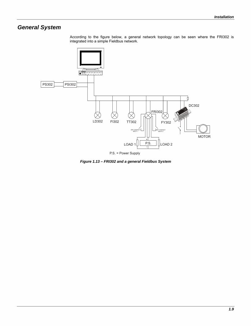
According to the figure below, a general network topology can be seen where the FRI302 is integrated into a simple Fieldbus network.
+
-
FRI302
DC302
MOTOR
FY302
PSI302PS302
TT302FI302LD302
P.S.
P.S. = Power Supply
LOAD 2LOAD 1
12
3
45
67
910
11
12
13
14
15
16
12
34
56
7COM
VDC
VIN
VOUT
INOUT
OUT 6OUT 8
IN 7
OUT 3OUT 5
OUT 7
smar
DC302-10
8
8SAVING
IN 10IN 9 IN 12IN 11
GNDVDC
DRY CONTACT INPUT 1
DRY CONTACT INPUT 2
Figure 1.13 – FRI302 and a general Fieldbus System

FRI302 – Operation and Maintenance Instruction Manual
1.10

Section 2
2.1
OPERATION The FRI302 has 2 isolated built-in relay outputs. It is therefore ideal for interfacing existing discrete devices to a Fieldbus system. Output function blocks include standard FOUNDATION™ safety mechanisms in case of failures. Outputs are isolated from each other.
NOTE For each output there is a 250mA protection fuse. To access them, please, remove the main electronic board and in the Relay board see the reference FU1 and FU2. The code for them is LIT 251.250 – 0.250A – from LittelFuse.
Functional Description – Electronics
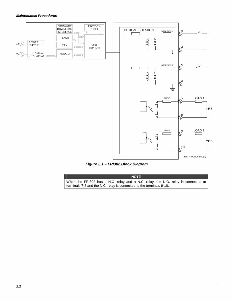
Refer to the block diagram (See Figure 2.1 – FRI302 Block Diagram). The function of each block is described below.
(CPU) Central Processing Unit, RAM and FLASH
The CPU is the intelligent portion of the Fieldbus Relay and dry contact Input, being responsible for the management and operation of block execution, self-diagnostics and communication. The program is stored in Flash memory. For temporary storage of data there is a RAM. The data in the RAM is lost if the power is switched off. However, the device also has a nonvolatile EEPROM where data that must be retained are stored. Examples of such data are configuration and identification data. Communication Controller It monitors line activity, modulates and demodulates the signal from the network. Power Supply Takes power of the loop-line to power the converter circuitry. Display Controller Receives data from the CPU and drives the Liquid Crystal Display. Local Adjustment There are two switches that are magnetically activated. They can be activated by the magnetic tool without mechanical or electrical contact. Optical Isolation Optical isolation is for outputs and inputs.
Maintenance Procedures
2.2
P.S. = Power Supply
OPTICAL ISOLATION
P.S.
LOAD 2FUSE 9
10
MODEM
RAM
FLASH
FIRMWAREDOWNLOADINTERFACE
FACTORYRESET
CPUEEPROM
POWERSUPPLY
SIGNALSHAPING
1+
2-
INTERFACE 2
INTERFACE 1 3
4
5
6
P.S.
LOAD 1FUSE 7
8
Figure 2.1 – FRI302 Block Diagram
NOTE When the FRI302 has a N.O. relay and a N.C. relay, the N.O. relay is connected to terminals 7-8 and the N.C. relay is connected to the terminals 9-10.

Section 3
3.1
CONFIGURATION One of the many advantages of Fieldbus is that device configuration is independent of the configuration tool. The FRI302 may be configured by a third party host computer using the DD (Device Description) and CFF (Capability File). The FRI302 has several Function Blocks built in, such as Analog Alarm, Arithmetic, Discrete Output, Flip-Flop and Edge Trigger, Input Selector, PID, Step Output PID and Timer. See “Function Block type availability and initial block set” at the end of this section. Function Blocks are not covered in this manual. For explanation and details of function blocks, see the Function Blocks Manual. The FRI302 Function Blocks can link with blocks located in other devices using SYSCON or other Fieldbus configuration tools. The relay outputs are chosen via CHANNEL parameter in the DO and PID Step blocks. For explanation and details for using SYSCON, please see the SYSCON Manual.
Functional Diagram
DO
1 & 2
STEPPID
OTHERFUNCTIONAL
BLOCKS
LINKSFROM OTHER
FUNCTIONAL BLOCKS
LOAD 1
FUSE 7
8
LOAD 2
FUSE 9
10
OUTPUT MODULE
INTERFACE 2
INTERFACE 1 3
4
5
6
DI
DI
Figure 3.1 – Functional Diagram

FRI302 – Operation and Maintenance, Instruction Manual
3.2
Output Transducer Blocks Description Using the transducer block the user can see the output relay type definition. Supported Modes Out Of Service (OOS) and Auto Parameters
Idx Parameter DataType Valid Range Default Value Units Store Description
1 ST_REV Unsigned16 0 None S Indicates the level of static data.
2 TAG_DESC VisibleString Null Na S Description of Transducer Block.
3 STRATEGY Unsigned16 0 None S This parameter is not checked and processed by Transducer Block.
4 ALERT_KEY Unsigned8 1 to 255 0 None S Number of identification in the plant.
5 MODE_BLK DS-69 O/S Na S Indicates the operation mode of Transducer Block.
6 BLOCK_ERR Bit String E D Indicates the status associated with hardware or software in theTransducer.
7 UPDATE_EVT DS-73 0: Serial 1: TCP/IP
Na D It is the alert for any static data.
8 BLOCK_ALM DS-72 0: Master 1: Slave
Na D It is used for configuration, hardware and others fails.
9 TRANSDUCER_DIRECTORY Unsigned16 None S
A directory that specifies the number and the starting indices of the transducers in the transducer block.
10 TRANSDUCER_TYPE Unsigned16 Other (0xffff) Other (0xffff) None S Identifies the transducer
that follows.
11 XD_ERROR Unsigned8
Default Value Set (0x10) General Error (0x11) Calibration Error (0x12) Configuration Error (0x13) Electronics Failure (0x14) Mechanical Failure (0x15) I/O Failure (0x16) Data Integrity Error (0x17) Software Error (0x18) Algorithm Error (0x19)
Default Value Set
(0x10)
None D Define an error code.
12 COLLECTION_DIRECTORY Unsigned 0 0 None S
A directory that specifies the number, the starting indices, and DD Item IDs of data collections in each transducers in the transducer block.
13 OUTPUT_RELAY_TYPE Unsigned8
Not Initialized. (0x0) Both Normally Open. (0x1) Both Normally Closed. (0x2) One Normally Open and another Normally Closed. (0x3)
Not Initialized
(0x0) None S The type of each output
relay.
14 SERIAL_NUMBER Unsigned32 0 to 4294967296 0 None S The device serial number
15 ORDERING_CODE Visible String[50] - Null None S
Indicates informations about the sensor and control from production factory.

Configuration
3.3
Legend: E – Enumerated parameter S – Static Null – Blank Sec – Seconds Na – Admensional parameter CU – CAL_UNIT RO – Read only PVR – PRIMARY_VALUE_RANGE D – Dynamic SR – SENSOR_RANGE N – Non-volatile SVU – SECONDARY_VALUE_RANGE Connecting physical signals to Digital Output Block
The DO block converts the value in SP_D to an on/off signal for the hardware found at the CHANNEL selection. The FRI302 can have up two DO blocks. For details, please see the Function Blocks Manual.
P.S.
LOAD 1
TRD
DO
CHANNEL 1
OUT_D
LOAD 2
P.S.
TRD
DO
CHANNEL 2
OUT_D
P.S. = Power Supply
Figure 3.2 - FRI302 and DO Block connections
Connecting physical signals to PID Step A Step Control Output block is used most commonly, when the final control element has an actuator driven by an electric motor without actual position feedback. The final control element is positioned by rotating the motor clockwise or counter clockwise, which is accomplished by activating a discrete signal for each direction. A control valve, for example, needs a signal to open and another to close. If none of the signals are present, the valve stem would stay at the same position. The FRI302 has one Step Control Block. For details, please see the Function Block Manual. Please, note the limits for switching current and voltage according to FRI302 technical specifications. The FRI302 outputs may not be able to drive the actuator motor, but can be used as control signals.

FRI302 – Operation and Maintenance, Instruction Manual
3.4
TRDPID STEP
CHANNEL =
= 1 or 2
OUT_1 RELAY OUT1
RELAY OUT2*
*
Figure 3.3 – FRI302 and PID Step Block Examples of Applications
Application 1: from the computer the outputs can be manipulated.
(VALUE, STATUS)
ALARM SIGNALLAMP
H1
DO
OUT
Figure 3.4 - FRI302 – Application 1 Application 2: Alarm control (Level limit will turn on alarm signal lamp or a buzzer).
H1
ALARM SIGNALLAMP
DD
A1
ALM
LD302
LEVELTRD
OUT 1
TRD
Figure 3.5 - FRI302 – Application 2
NOTE One very interesting application for FRI302 is as an interface for electrical actuators. Any electrical actuator, including the Smar series AD/AR/AL becomes a Fieldbus actuator, making the FRI302 ideal in upgrades and plant re-instrumentations. The PID Step block is ideal in these cases since it can modulate the valve without the need for actual position feedback.

Configuration
3.5
Function Block type availability and initial block set
The table below shows the function blocks supported by this device and the initial block set. Read carefully the notes in order to fully understand the information in this table.
Note 1 – The column “Block type” indicates which block type is available for the device. Note 2 – The number associated to the block type is the number of instantiated blocks during the factory initialization. Note 3 – the FRI302 have a capability of 20 blocks, including resource, transducers and function blocks. Note 4 – The column Block type shows the mnemonics, if it is followed by a number between parentheses, it indicates the maximum number of block instances. If it is followed by “*”, it indicates the maximum number depends on the device type.
Block type Instantiable block in Factory init
RS (1) 1 TRD (1) 1 DIAG (1) 1 DSP (1) 1 DI (2) 2 DO (2) 2
PID 1 ARTH 1 AALM 1 ISEL 1 TIME 1 FFET 1 STEP 1

FRI302 – Operation and Maintenance, Instruction Manual
3.6

Section 4
4.1
MAINTENANCE PROCEDURES General
SMAR FRI302 Fieldbus Relay and dry contact Input devices are extensively tested and inspected before delivery to the end user. Nevertheless, during their design and development, consideration has been given to the possibility of repairs by the end user, when necessary. In general, it is recommended for the end user not to try to repair printed circuit boards. Instead, spare circuit boards should be available, which may be ordered from SMAR when necessary.
Troubleshooting Symptom Probable Sources of Trouble
No Quiescent Current
Fieldbus Relay and dry contact Input Connections: Check wiring polarity and continuity. Power Supply: Check power supply output. The voltage at the FRI302 Fieldbus terminals must be between 9 and 32 VDC. Electronic Circuit Failure: Check the boards for defects by replacing them with spare ones.
No Communication
Network Connections Check the network connections: devices, power supply, and terminators. Network Impedance Check the network impedance (power supply impedance and terminators). Controller Configuration Check configuration of communication parameters of the controller. Network Configuration Check communication configuration of the network. Electronic Circuit Failure Check the boards for defects by replacing them with spare ones.
Incorrect Outputs
Output Terminals Connection Check wiring and continuity. Switching Current and voltage for Outputs Check limits for the connected load according to the model for relay connections. Output Fuse Check the condition Of the output Fuses by removing the main electronic board.
Disassembly Procedure See Figure 4.1 – FRI302 Exploded View. Make sure to disconnect the power supply before disassembling the converter. To remove the circuit boards (5 and 6) and display (4), first loosen the cover locking (7) on the side not marked “Field Terminals”, then unscrew the cover (1).
WARNING The boards have CMOS components, which may be damaged by electrostatic discharges. Observe correct procedures for handling CMOS components. It is also recommended to store the circuit boards in electrostatic-proof cases.
Loosen the two screws (3) that anchor the display and the main circuit board. Gently pull out the display (4), and then the main board (5). To remove the input board (6), first unscrew the two screws that anchor it to the housing (15), and gently pull out the board.

FRI302- Operation and Maintenance, Instruction Manual
4.2
Reassembly Procedure Place the input board (6) into housing (15); Place the main board (5) into the housing (15), ensuring all inter connecting pins are connected; Place the display (4) into the housing, note the four mounting positions. "_" should point in
the direction desired as UP; Anchor main board (5) and display with their screws (3); Fit the cover (1 and 13) and lock it using the locking screws (7 and 18).
1
2
183
4
5
6
7
8
9
10
11
12
13
15
16
17
Figure 4.1 – FRI302 Exploded View
Figure 4.2 – FRI302 Identification Plate

Section 5
5-1
TECHNICAL SPECIFICATIONS
General
Communication Digital only. Fieldbus, 31.25 Kbits/s voltage mode
Current consumption quiescent 17.5 mA from Fieldbus network
Turn-on Time Approximately 10 seconds.
Update Time Approximately 0.5 second.
Humidity Limits 0 to 100% RH.
Indication Optional 4½ digit LCD indicator.
Temperature Limits
Operation: -40 to 85ºC (-40 to 185 ºF). Storage: -40 to 120ºC (-40 to 250 ºF). Display: -10 to 60ºC (14 to 140ºF) operation; -40 to 85ºC (-40 to 185 ºF) without damage.
Vibration Effect Meets SAMA PMC 31.1.
Electro-Magnetic Interference Effect Designed to comply with IEC 801.
Hardware Physical: according to IEC 61158-2 and conformity with the FISCO model.
Electrical Connection 1/2-14 NPT, PG 13.5 or M20 x 1.5.
Material of Construction Injected low copper aluminum with polyester painting or 316 Stainless Steel housing, with Buna N O-rings on cover (NEMA 4X, IP67).
Mounting With an optional bracket that can be installed on a 2" pipe or fixed on a wall or panel.
Weight Without display and mounting bracket: 0.80 kg. Add for digital display: 0.13 kg. Add for mounting bracket: 0.60 kg.
FRI302 Output Relays
Description - Outputs The outputs are designed with Solid State relays that are able to drive incandescence lamps, solenoids and other DC and AC loads. When the output relays are N.C., if via function block is assigned a state on to the outputs, it means that the loads will be switched off. When the output relays are N.O., if via function block is assigned a state on to the outputs, it means that the loads will be switched on.

Technical Characteristics
5.2
Technical specifications for Normally Closed relays
Architecture Number of Outputs: 2
Switching Voltage 350 Vpeak
Switching Current: AC mode 100 mA
Switching Current: DC mode 165 mA
On Resistance AC mode 18 Ω
On Resistance DC mode 4.5 Ω
Off State Resistance Min: 0.1 GΩ Typ: 1.4 GΩ
Off State Leakage Typ: 1.0 µA
Turn On Time 5ms
Turn Off Time 1ms
Capacitance - Across Output 20 to 200 pF
Thermal Offset Voltage 0.20mV
Output Status (load) with no power supply connected to the H1 bus ON
Output Status (load) During: Firmware Download ON
Output Status (load) During: Turn-on Time ON
Output Status (load) During: Configuration Download OFF
Technical specifications for Normally Opened relays
Architecture Number of Outputs: 2
Switching Voltage 400 Vpeak
Switching Current: AC mode 150 mA
Switching Current: DC mode 250 mA
On Resistance AC mode 18 Ω
On Resistance DC mode 4.5 Ω
Off State Resistance Min: 0.5 GΩ Typ: 5000 GΩ
Off State Leakage Typ: 0.5 µA
Turn On Time 5ms
Turn Off Time 1ms
Capacitance - Across Output 10 to 95 pF
Thermal Offset Voltage 0.20mV
Output Status (load) with no power supply connected on the H1 bus OFF
Output Status (load) During: Firmware Download OFF
Output Status (load) During: Turn-on Time OFF
Output Status (load) During: Configuration Download ON

FRI302- Operation and Maintenance, Instruction Manual
5-3
Technical Specifications for Dry Contact Input
Digital Input
2 (two) dry contact inputs, galvanically isolated between other:
Resistance below 2 KΩ, closed contact;
Resistance above 3.5 KΩ, open contact.
Ordering Code
MODEL FRI302 FIELDBUS RELAY AND DRY CONTACT INPUT COD. Local Indicator
0 1
Without Indicator With Digital Indicator
COD. Relay Output Condition
1 2 3
Both Normally Open (N.O.) Both Normally Closed (N.C.) One N.O. and other N.C.
COD. Mounting Bracket for 2" Pipe Mounting
0 1 2
Without Bracket Carbon Steel Bracket 316 SST Bracket
COD. Electrical Connections
0 A B
1/2-14 NPT M20 x 1.5 PG 13.5 DIN
COD. Options
H0 H1 A1 ZZ
Housing - Aluminum (IP/TYPE) Housing - 316 SST (IP/TYPE) 316 SST Bolts Special Options – Specify
FRI302 - 1 1 - 1 0 / Leave it blank for no optional items

Technical Characteristics
5.4
Appendix A
A.1
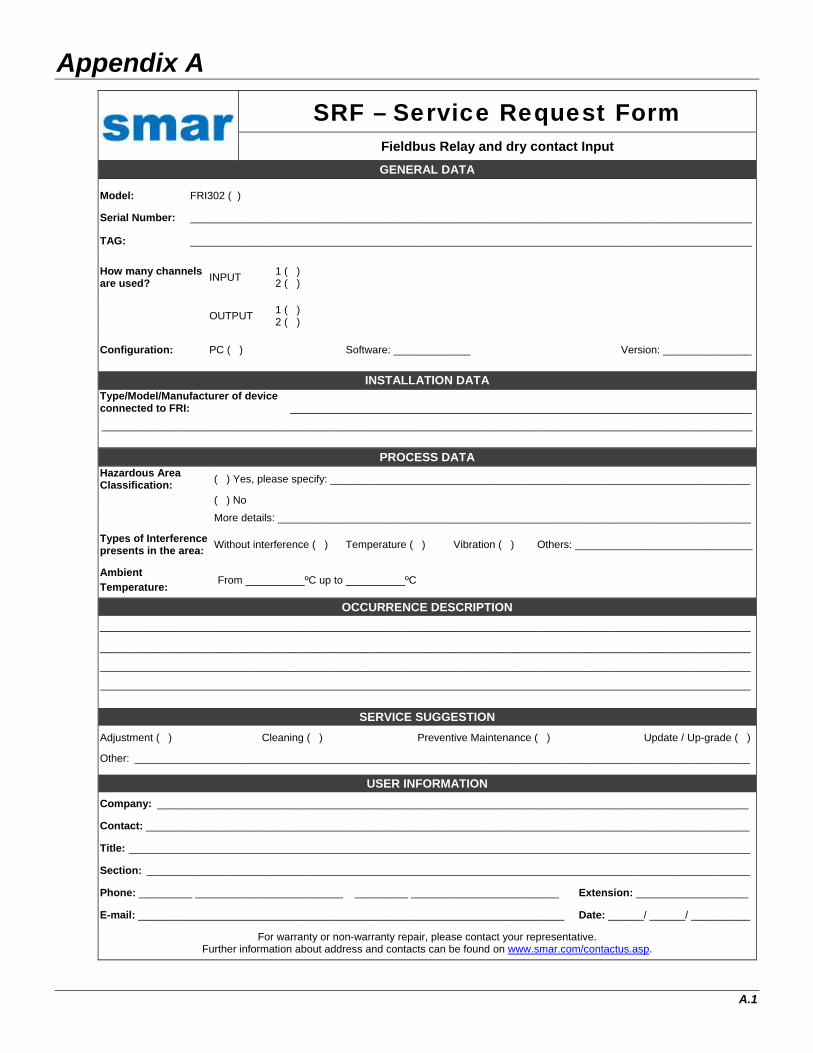
SRF – Service Request Form Fieldbus Relay and dry contact Input
GENERAL DATA
Model: FRI302 ( )
Serial Number: _______________________________________________________________________________________________
TAG: _______________________________________________________________________________________________
How many channels are used?
INPUT 1 ( ) 2 ( )
OUTPUT 1 ( ) 2 ( )
Configuration: PC ( ) Software: _____________ Version: _______________
INSTALLATION DATA Type/Model/Manufacturer of device connected to FRI: ______________________________________________________________________________
______________________________________________________________________________________________________________
PROCESS DATA Hazardous Area Classification:
( ) Yes, please specify: _______________________________________________________________________
( ) No
More details: ________________________________________________________________________________
Types of Interference presents in the area:
Without interference ( ) Temperature ( ) Vibration ( ) Others: ______________________________
Ambient Temperature: From __________ºC up to __________ºC
OCCURRENCE DESCRIPTION
______________________________________________________________________________________________________________
______________________________________________________________________________________________________________
______________________________________________________________________________________________________________
______________________________________________________________________________________________________________
SERVICE SUGGESTION
Adjustment ( ) Cleaning ( ) Preventive Maintenance ( ) Update / Up-grade ( )
Other: ________________________________________________________________________________________________________
USER INFORMATION
Company: ____________________________________________________________________________________________________
Contact: ______________________________________________________________________________________________________
Title: _________________________________________________________________________________________________________
Section: ______________________________________________________________________________________________________
Phone: _________ _________________________ _________ _________________________ Extension: ___________________
E-mail: ________________________________________________________________________ Date: ______/ ______/ __________
For warranty or non-warranty repair, please contact your representative. Further information about address and contacts can be found on www.smar.com/contactus.asp.

FRI302 - Operation and Maintenance Instruction Manual
A.2
Returning Materials If necessary to return the FRI302 to SMAR, simply contact our office, informing the defective instrument serial number, and return it to our factory. In order to speed up analysis and solution of the problem, the defective item should be returned with a description of the failure observed, with as much details as possible. Other information concerning the instrument operation, such as service and process conditions, is also helpful. Instruments returned or to be revised outside the guarantee term should be accompanied by a purchase order or a quote request.