Embed Size (px)
Citation preview
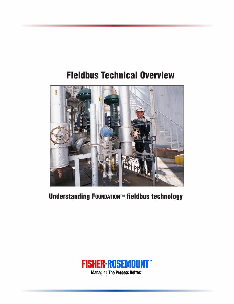
Fieldbus Technical Overview
Understanding FOUNDATION™ fieldbus technology
Table of Contents
FOUNDATION fieldbus—the technology of the future available today . . . . . . . . . . . . . . . . . . . . . . . . .1
Tell me more about the benefits of fieldbus . . . . . . . . . . . . . . . . . . . . . . . . . . . . . . . . . . . . . . . . . . . .1Planning and Installation . . . . . . . . . . . . . . . . . . . . . . . . . . . . . . . . . . . . . . . . . . . . . . . . . . . . . . . . . . . . . . . .1Operation . . . . . . . . . . . . . . . . . . . . . . . . . . . . . . . . . . . . . . . . . . . . . . . . . . . . . . . . . . . . . . . . . . .2Maintenance . . . . . . . . . . . . . . . . . . . . . . . . . . . . . . . . . . . . . . . . . . . . . . . . . . . . . . . . . . . . . . . . . . .2Interoperability—another key benefit of fieldbus technology . . . . . . . . . . . . . . . . . . . . . . . . . . . . . . . . . . . .2
FOUNDATION fieldbus technology . . . . . . . . . . . . . . . . . . . . . . . . . . . . . . . . . . . . . . . . . . . . . . . . . . . . .3Physical Layer . . . . . . . . . . . . . . . . . . . . . . . . . . . . . . . . . . . . . . . . . . . . . . . . . . . . . . . . . . . . . . . . . . .4
H1 Fieldbus . . . . . . . . . . . . . . . . . . . . . . . . . . . . . . . . . . . . . . . . . . . . . . . . . . . . . . . . . . . . . . . . . . .4H1 Fieldbus Signaling . . . . . . . . . . . . . . . . . . . . . . . . . . . . . . . . . . . . . . . . . . . . . . . . . . . . . . . . . . .4H1 Fieldbus Wiring . . . . . . . . . . . . . . . . . . . . . . . . . . . . . . . . . . . . . . . . . . . . . . . . . . . . . . . . . . . . . .5
High speed fieldbus . . . . . . . . . . . . . . . . . . . . . . . . . . . . . . . . . . . . . . . . . . . . . . . . . . . . . . . . . . . . . . . . 6
Communications Stack . . . . . . . . . . . . . . . . . . . . . . . . . . . . . . . . . . . . . . . . . . . . . . . . . . . . . . . . . . . . . . . . .7Data Link Layer . . . . . . . . . . . . . . . . . . . . . . . . . . . . . . . . . . . . . . . . . . . . . . . . . . . . . . . . . . . . . . . . . . .7
Device Types . . . . . . . . . . . . . . . . . . . . . . . . . . . . . . . . . . . . . . . . . . . . . . . . . . . . . . . . . . . . . . . . . .7Scheduled Communications . . . . . . . . . . . . . . . . . . . . . . . . . . . . . . . . . . . . . . . . . . . . . . . . . . . . . . .7Unscheduled Communications . . . . . . . . . . . . . . . . . . . . . . . . . . . . . . . . . . . . . . . . . . . . . . . . . . . . .7Link Active Scheduler Operation . . . . . . . . . . . . . . . . . . . . . . . . . . . . . . . . . . . . . . . . . . . . . . . . . . .7
CD Schedule . . . . . . . . . . . . . . . . . . . . . . . . . . . . . . . . . . . . . . . . . . . . . . . . . . . . . . . . . . . . . . .7Live List Maintenance . . . . . . . . . . . . . . . . . . . . . . . . . . . . . . . . . . . . . . . . . . . . . . . . . . . . . . . .8Data Link Time Synchronization . . . . . . . . . . . . . . . . . . . . . . . . . . . . . . . . . . . . . . . . . . . . . . . .8Token Passing . . . . . . . . . . . . . . . . . . . . . . . . . . . . . . . . . . . . . . . . . . . . . . . . . . . . . . . . . . . . . .8LAS Redundancy . . . . . . . . . . . . . . . . . . . . . . . . . . . . . . . . . . . . . . . . . . . . . . . . . . . . . . . . . . . .8
Fieldbus Access Sublayer . . . . . . . . . . . . . . . . . . . . . . . . . . . . . . . . . . . . . . . . . . . . . . . . . . . . . . . . . . . .9Client/Server VCR Type . . . . . . . . . . . . . . . . . . . . . . . . . . . . . . . . . . . . . . . . . . . . . . . . . . . . . . . . . .9Report Distribution VCR Type . . . . . . . . . . . . . . . . . . . . . . . . . . . . . . . . . . . . . . . . . . . . . . . . . . . . .9Publisher/Subscriber VCR Type . . . . . . . . . . . . . . . . . . . . . . . . . . . . . . . . . . . . . . . . . . . . . . . . . . . .9
Fieldbus Message Specification (FMS) . . . . . . . . . . . . . . . . . . . . . . . . . . . . . . . . . . . . . . . . . . . . . . . . . .10Virtual Field Device(VFD) . . . . . . . . . . . . . . . . . . . . . . . . . . . . . . . . . . . . . . . . . . . . . . . . . . . . . . . .10Communication Services . . . . . . . . . . . . . . . . . . . . . . . . . . . . . . . . . . . . . . . . . . . . . . . . . . . . . . . . .11
Context Management Services . . . . . . . . . . . . . . . . . . . . . . . . . . . . . . . . . . . . . . . . . . . . . . . . .11Object Dictionary Services . . . . . . . . . . . . . . . . . . . . . . . . . . . . . . . . . . . . . . . . . . . . . . . . . . . .11Variable Access Services . . . . . . . . . . . . . . . . . . . . . . . . . . . . . . . . . . . . . . . . . . . . . . . . . . . . . .11Event Services . . . . . . . . . . . . . . . . . . . . . . . . . . . . . . . . . . . . . . . . . . . . . . . . . . . . . . . . . . . . .11Upload/Download Services . . . . . . . . . . . . . . . . . . . . . . . . . . . . . . . . . . . . . . . . . . . . . . . . . . . .11Program Invocation Services . . . . . . . . . . . . . . . . . . . . . . . . . . . . . . . . . . . . . . . . . . . . . . . . . . .11
Message Formatting . . . . . . . . . . . . . . . . . . . . . . . . . . . . . . . . . . . . . . . . . . . . . . . . . . . . . . . . . . . . .12Protocol Behavior . . . . . . . . . . . . . . . . . . . . . . . . . . . . . . . . . . . . . . . . . . . . . . . . . . . . . . . . . . . . . .12
User Application—Blocks . . . . . . . . . . . . . . . . . . . . . . . . . . . . . . . . . . . . . . . . . . . . . . . . . . . . . . . . . . . . . . .13Resource Blocks . . . . . . . . . . . . . . . . . . . . . . . . . . . . . . . . . . . . . . . . . . . . . . . . . . . . . . . . . . . . . . . .13Function Block . . . . . . . . . . . . . . . . . . . . . . . . . . . . . . . . . . . . . . . . . . . . . . . . . . . . . . . . . . . . . . . . .13Transducer Blocks . . . . . . . . . . . . . . . . . . . . . . . . . . . . . . . . . . . . . . . . . . . . . . . . . . . . . . . . . . . . . .14Fieldbus Device Definition . . . . . . . . . . . . . . . . . . . . . . . . . . . . . . . . . . . . . . . . . . . . . . . . . . . . . . . .15
SSyysstteemm MMaannaaggeemmeenntt .. .. .. .. .. .. .. .. .. .. .. .. .. .. .. .. .. .. .. .. .. .. .. .. .. .. .. .. .. .. .. .. .. .. .. .. .. .. .. .. .. .. .. .. .. .. .. .. .. .. .. .. .. .. .. .. .. .. .. .. .. .. .. .. .. .. ..1177Function Block Scheduling . . . . . . . . . . . . . . . . . . . . . . . . . . . . . . . . . . . . . . . . . . . . . . . . . . . . . . . . . . .17
Application Clock Distribution . . . . . . . . . . . . . . . . . . . . . . . . . . . . . . . . . . . . . . . . . . . . . . . . . . . . .18Device Address Assignment . . . . . . . . . . . . . . . . . . . . . . . . . . . . . . . . . . . . . . . . . . . . . . . . . . . . . . .18Find Tag Service . . . . . . . . . . . . . . . . . . . . . . . . . . . . . . . . . . . . . . . . . . . . . . . . . . . . . . . . . . . . . . .18
DDeevviiccee DDeessccrriippttiioonnss .. .. .. .. .. .. .. .. .. .. .. .. .. .. .. .. .. .. .. .. .. .. .. .. .. .. .. .. .. .. .. .. .. .. .. .. .. .. .. .. .. .. .. .. .. .. .. .. .. .. .. .. .. .. .. .. .. .. .. .. .. .. .. .. .. .. ..1199Device Description Tokenizer . . . . . . . . . . . . . . . . . . . . . . . . . . . . . . . . . . . . . . . . . . . . . . . . . . . . . . . . .19Device Description Services . . . . . . . . . . . . . . . . . . . . . . . . . . . . . . . . . . . . . . . . . . . . . . . . . . . . . . . . . .20Device Description Hierarchy . . . . . . . . . . . . . . . . . . . . . . . . . . . . . . . . . . . . . . . . . . . . . . . . . . . . . . . . .20Interoperability . . . . . . . . . . . . . . . . . . . . . . . . . . . . . . . . . . . . . . . . . . . . . . . . . . . . . . . . . . . . . . . . . . .21
SSyysstteemm CCoonnffiigguurraattiioonn .. .. .. .. .. .. .. .. .. .. .. .. .. .. .. .. .. .. .. .. .. .. .. .. .. .. .. .. .. .. .. .. .. .. .. .. .. .. .. .. .. .. .. .. .. .. .. .. .. .. .. .. .. .. .. .. .. .. .. .. ..2222SSyysstteemm DDeessiiggnn .. .. .. .. .. .. .. .. .. .. .. .. .. .. .. .. .. .. .. .. .. .. .. .. .. .. .. .. .. .. .. .. .. .. .. .. .. .. .. .. .. .. .. .. .. .. .. .. .. .. .. .. .. .. .. .. .. .. .. .. .. .. .. .. .. .. ..2222DDeevviiccee CCoonnffiigguurraattiioonn .. .. .. .. .. .. .. .. .. .. .. .. .. .. .. .. .. .. .. .. .. .. .. .. .. .. .. .. .. .. .. .. .. .. .. .. .. .. .. .. .. .. .. .. .. .. .. .. .. .. .. .. .. .. .. .. .. .. .. .. .. .. ..2222
FFOOUUNNDDAATTIIOONN ffiieellddbbuuss——rreeaaddyy,, sseett,, ggoo!! .. .. .. .. .. .. .. .. .. .. .. .. .. .. .. .. .. .. .. .. .. .. .. .. .. .. .. .. .. .. .. .. .. .. .. .. .. .. .. .. .. .. .. .. .. .. .. .. .. .. .. .. .. .. .. .. ..2233
Copyright Fisher-Rosemount Systems 1998. All Rights Reserved. This document contains excerpts of copyrightedmaterials that are the property of the Fieldbus Foundation and are reproduced with its express written permission.Fisher-Rosemount, Managing the Process Better, PlantWeb, and RS3 are marks of one of the Fisher-Rosemount familyof companies. FOUNDATION is a mark of the Fieldbus Foundation. All other marks are the property of their respectiveowners. The contents of this publication are presented for informational purposes only, and while every effort has beenmade to ensure their accuracy, they are not to be construed as warranties or guarantees, express or implied, regardingthe products or services described herein or their use or applicability. All sales are governed by our terms andconditions, which are available on request. We reserve the right to modify or improve the designs or specifications of ourproducts at any time without notice.
1
FOUNDATION™ fieldbus—thetechnology of tomorrow—available today.
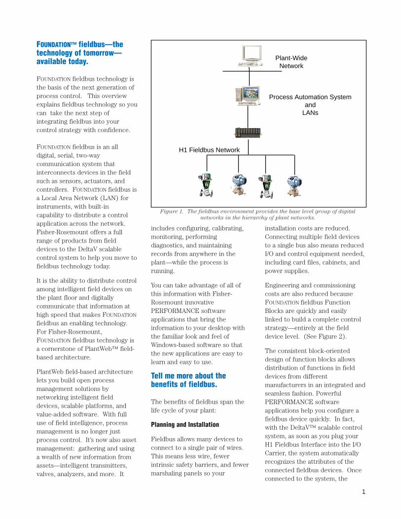
FOUNDATION fieldbus technology isthe basis of the next generation ofprocess control. This overviewexplains fieldbus technology so youcan take the next step ofintegrating fieldbus into yourcontrol strategy with confidence.
FOUNDATION fieldbus is an alldigital, serial, two-waycommunication system thatinterconnects devices in the fieldsuch as sensors, actuators, andcontrollers. FOUNDATION fieldbus isa Local Area Network (LAN) forinstruments, with built-incapability to distribute a controlapplication across the network.Fisher-Rosemount offers a fullrange of products from fielddevices to the DeltaV scalablecontrol system to help you move tofieldbus technology today.
It is the ability to distribute controlamong intelligent field devices onthe plant floor and digitallycommunicate that information athigh speed that makes FOUNDATION
fieldbus an enabling technology.For Fisher-Rosemount,FOUNDATION fieldbus technology isa cornerstone of PlantWeb™ field-based architecture.
PlantWeb field-based architecturelets you build open processmanagement solutions bynetworking intelligent fielddevices, scalable platforms, andvalue-added software. With fulluse of field intelligence, processmanagement is no longer justprocess control. It’s now also assetmanagement: gathering and usinga wealth of new information fromassets—intelligent transmitters,valves, analyzers, and more. It
Plant-WideNetwork
Process Automation Systemand
LANs
H1 Fieldbus Network
includes configuring, calibrating,monitoring, performingdiagnostics, and maintainingrecords from anywhere in theplant—while the process isrunning.
You can take advantage of all ofthis information with Fisher-Rosemount innovativePERFORMANCE softwareapplications that bring theinformation to your desktop withthe familiar look and feel ofWindows-based software so thatthe new applications are easy tolearn and easy to use.
Tell me more about thebenefits of fieldbus.
The benefits of fieldbus span thelife cycle of your plant:
Planning and Installation
Fieldbus allows many devices toconnect to a single pair of wires.This means less wire, fewerintrinsic safety barriers, and fewermarshaling panels so your
installation costs are reduced.Connecting multiple field devicesto a single bus also means reducedI/O and control equipment needed,including card files, cabinets, andpower supplies.
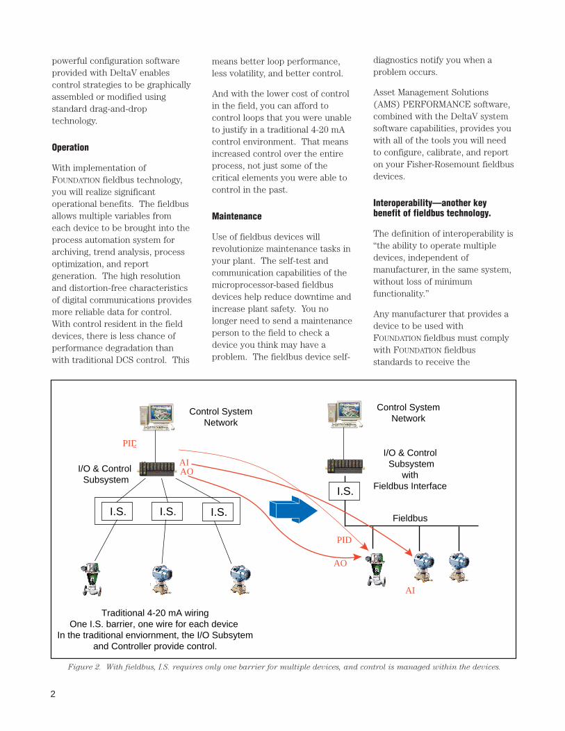
Engineering and commissioningcosts are also reduced becauseFOUNDATION fieldbus FunctionBlocks are quickly and easilylinked to build a complete controlstrategy—entirely at the fielddevice level. (See Figure 2).
The consistent block-orienteddesign of function blocks allowsdistribution of functions in fielddevices from differentmanufacturers in an integrated andseamless fashion. PowerfulPERFORMANCE softwareapplications help you configure afieldbus device quickly. In fact,with the DeltaV™ scalable controlsystem, as soon as you plug yourH1 Fieldbus Interface into the I/OCarrier, the system automaticallyrecognizes the attributes of theconnected fieldbus devices. Onceconnected to the system, the
Figure 1. The fieldbus environment provides the base level group of digital
networks in the hierarchy of plant networks.
2
means better loop performance,less volatility, and better control.
And with the lower cost of controlin the field, you can afford tocontrol loops that you were unableto justify in a traditional 4-20 mAcontrol environment. That meansincreased control over the entireprocess, not just some of thecritical elements you were able tocontrol in the past.
Maintenance
Use of fieldbus devices willrevolutionize maintenance tasks inyour plant. The self-test andcommunication capabilities of themicroprocessor-based fieldbusdevices help reduce downtime andincrease plant safety. You nolonger need to send a maintenanceperson to the field to check adevice you think may have aproblem. The fieldbus device self-
powerful configuration softwareprovided with DeltaV enablescontrol strategies to be graphicallyassembled or modified usingstandard drag-and-droptechnology.
Operation
With implementation ofFOUNDATION fieldbus technology,you will realize significantoperational benefits. The fieldbusallows multiple variables fromeach device to be brought into theprocess automation system forarchiving, trend analysis, processoptimization, and reportgeneration. The high resolutionand distortion-free characteristicsof digital communications providesmore reliable data for control.With control resident in the fielddevices, there is less chance ofperformance degradation thanwith traditional DCS control. This
diagnostics notify you when aproblem occurs.
Asset Management Solutions(AMS) PERFORMANCE software,combined with the DeltaV systemsoftware capabilities, provides youwith all of the tools you will needto configure, calibrate, and reporton your Fisher-Rosemount fieldbusdevices.
Interoperability—another keybenefit of fieldbus technology.
The definition of interoperability is“the ability to operate multipledevices, independent ofmanufacturer, in the same system,without loss of minimumfunctionality.”
Any manufacturer that provides adevice to be used withFOUNDATION fieldbus must complywith FOUNDATION fieldbusstandards to receive the
Control SystemNetwork
I/O & Control Subsystem
Control SystemNetwork
Traditional 4-20 mA wiringOne I.S. barrier, one wire for each device
In the traditional enviornment, the I/O Subsytemand Controller provide control.
FieldbusI.S. I.S. I.S.
I.S.
PID
AOAI
AI
PID
AO
I/O & Control Subsystem
withFieldbus Interface
Figure 2. With fieldbus, I.S. requires only one barrier for multiple devices, and control is managed within the devices.
3
FOUNDATION fieldbus certification.That means that you haveincreased flexibility in supplierselection with the assurance thatall devices will work together,regardless of manufacturer.
FOUNDATION FieldbusTechnology
FOUNDATION fieldbus technologyconsists of three parts:
■ Physical Layer■ Communication “Stack”■ User Application
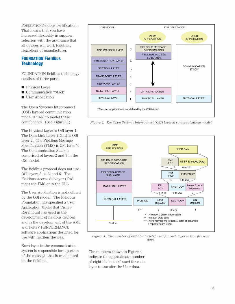
The Open Systems Interconnect(OSI) layered communicationmodel is used to model thesecomponents. (See Figure 3.)
The Physical Layer is OSI layer 1.The Data Link Layer (DLL) is OSIlayer 2. The Fieldbus MessageSpecification (FMS) is OSI layer 7.The Communication Stack iscomprised of layers 2 and 7 in theOSI model.
The fieldbus protocol does not useOSI layers 3, 4, 5, and 6. TheFieldbus Access Sublayer (FASmaps the FMS onto the DLL.
The User Application is not definedby the OSI model. The FieldbusFoundation has specified a UserApplication Model that Fisher-Rosemount has used in thedevelopment of fieldbus devicesand in the development of the AMSand DeltaV PERFORMANCEsoftware applications designed foruse with fieldbus devices.
Each layer in the communicationsystem is responsible for a portionof the message that is transmittedon the fieldbus.
APPLICATION LAYER 7
6
5
4
3
2
1
USERAPPLICATION
USERAPPLICATION
FIELDBUS MODELOSI MODEL*
*The user application is not defined by the OSI Model.
PRESENTATION LAYER
SESSION LAYER
TRANSPORT LAYER
NETWORK LAYER
DATA LINK LAYER
PHYSICAL LAYER
FIELDBUS MESSAGE SPECIFICATION
FIELDBUS ACCESSSUBLAYER
DATA LINK LAYER
PHYSICAL LAYER PHYSICAL LAYER
COMMUNICATION"STACK"
Figure 3. The Open Systems Interconnect (OSI) layered communications model.
EndDelimiter
FIELDBUS MESSAGE SPECIFICATION
USERAPPLICATION
* Protocol Control Information ** Protocol Data Unit*** There may be more than 1 octet of preamble if repeaters are used.
FIELDBUS ACCESSSUBLAYER
DATA LINK LAYER
PHYSICAL LAYERPreamble Start
DelimiterDLL PDU**
1*** 1 8-273 1
DLLPCI*
FAS PDU** Frame CheckSequence
5 to 15 5 to 256 2
FASPCI*
FMS PDU**
1 4 to 255
FMSPCI*
USER Encoded Data
4 0 to 251
USER Data
Fieldbus
Figure 4. The number of eight bit “octets” used for each layer to transfer user
data.
The numbers shown in Figure 4indicate the approximate numberof eight bit “octets” used for eachlayer to transfer the User data.
4
CLOCK
DATA 1
0
MANCHESTERBIPHASE-LENCODING
+
-
1 Bit Time
0 1 1 0 0
CLOCK
PREAMBLE
10
START DELIMITER
ENDDELIMITER
+0-
+0-
+0-
N+ N- 1 0 N+ N- 01
1
1
0 1 0 1 0 1 0
N+ N- N+ N- 1 1 0
Figure 5. Fieldbus signals are encoded using the Manchester Biphase-L technique.
Figure 6. Special characters are defined for the preamble, start delimiter, and end
delimiter.
Physical Layer
The Physical Layer is defined bystandards from the InternationalElectrotechnical Commission(IEC) and The InternationalSociety of Measurement andControl (ISA).
The Physical Layer receivesmessages from the communicationstack and converts the messagesinto physical signals on thefieldbus transmission medium andvice-versa.
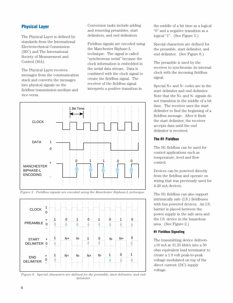
the middle of a bit time as a logical“0” and a negative transition as alogical “1”. (See Figure 5.)
Special characters are defined forthe preamble, start delimiter, andend delimiter. (See Figure 6.)
The preamble is used by thereceiver to synchronize its internalclock with the incoming fieldbussignal.
Special N+ and N- codes are in thestart delimiter and end delimiter.Note that the N+ and N- signals donot transition in the middle of a bittime. The receiver uses the startdelimiter to find the beginning of afieldbus message. After it findsthe start delimiter, the receiveraccepts data until the enddelimiter is received.
The H1 Fieldbus
The H1 fieldbus can be used forcontrol applications such astemperature, level and flowcontrol.
Devices can be powered directlyfrom the fieldbus and operate onwiring that was previously used for4-20 mA devices.
The H1 fieldbus can also supportintrinsically safe (I.S.) fieldbuseswith bus powered devices. An I.S.barrier is placed between thepower supply in the safe area andthe I.S. device in the hazardousarea. (See Figure 2.)
H1 Fieldbus Signaling
The transmitting device delivers±10 mA at 31.25 kbit/s into a 50ohm equivalent load terminator tocreate a 1.0 volt peak-to-peakvoltage modulated on top of thedirect current (DC) supplyvoltage.
Conversion tasks include addingand removing preambles, startdelimiters, and end delimiters.
Fieldbus signals are encoded usingthe Manchester Biphase-Ltechnique. The signal is called“synchronous serial” because theclock information is embedded inthe serial data stream. Data iscombined with the clock signal tocreate the fieldbus signal. Thereceiver of the fieldbus signalinterprets a positive transition in
5
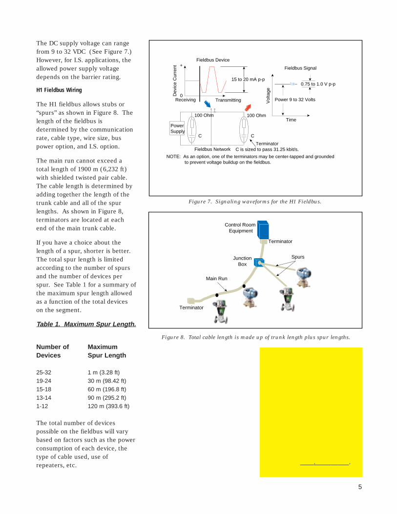
The DC supply voltage can rangefrom 9 to 32 VDC (See Figure 7.)However, for I.S. applications, theallowed power supply voltagedepends on the barrier rating.
H1 Fieldbus Wiring
The H1 fieldbus allows stubs or“spurs” as shown in Figure 8. Thelength of the fieldbus isdetermined by the communicationrate, cable type, wire size, buspower option, and I.S. option.
The main run cannot exceed atotal length of 1900 m (6,232 ft)with shielded twisted pair cable.The cable length is determined byadding together the length of thetrunk cable and all of the spurlengths. As shown in Figure 8,terminators are located at eachend of the main trunk cable.
If you have a choice about thelength of a spur, shorter is better.The total spur length is limitedaccording to the number of spursand the number of devices perspur. See Table 1 for a summary ofthe maximum spur length allowedas a function of the total deviceson the segment.
Table 1. Maxim um Spur Length.
Number of MaximumDevices Spur Length
25-32 1 m (3.28 ft)19-24 30 m (98.42 ft)15-18 60 m (196.8 ft)13-14 90 m (295.2 ft)1-12 120 m (393.6 ft)
The total number of devicespossible on the fieldbus will varybased on factors such as the powerconsumption of each device, thetype of cable used, use ofrepeaters, etc.
Receiving Transmitting
+
0
Fieldbus Device
Dev
ice
Cur
rent
15 to 20 mA p-p
PowerSupply
100 Ohm100 Ohm
C
Fieldbus NetworkTerminator
C is sized to pass 31.25 kbit/s.
NOTE: As an option, one of the terminators may be center-tapped and grounded to prevent voltage buildup on the fieldbus.
Vol
tage
Time
Fieldbus Signal
0.75 to 1.0 V p-p
Power 9 to 32 Volts
C
Figure 7. Signaling waveforms for the H1 Fieldbus.
Control Room Equipment
JunctionBox
Terminator
Terminator
Spurs
Main Run
Figure 8. Total cable length is made up of trunk length plus spur lengths.
. .
6
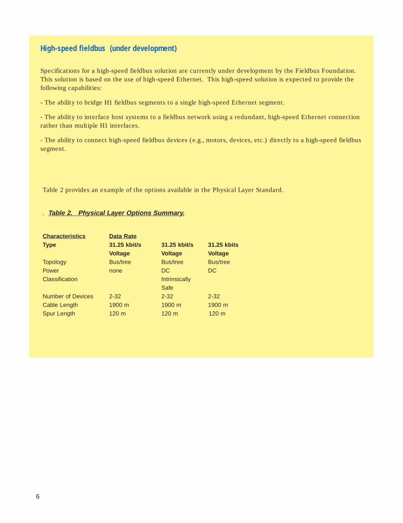
High-speed fieldbus (under development)
Specifications for a high-speed fieldbus solution are currently under development by the Fieldbus Foundation.This solution is based on the use of high-speed Ethernet. This high-speed solution is expected to provide thefollowing capabilities:
- The ability to bridge H1 fieldbus segments to a single high-speed Ethernet segment.
- The ability to interface host systems to a fieldbus network using a redundant, high-speed Ethernet connectionrather than multiple H1 interfaces.
- The ability to connect high-speed fieldbus devices (e.g., motors, devices, etc.) directly to a high-speed fieldbussegment.
Table 2 provides an example of the options available in the Physical Layer Standard.
. Table 2. Physical La yer Options Summar y.
Characteristics Data RateType 31.25 kbit/s 31.25 kbit/s 31.25 kbits
Voltage Voltage VoltageTopology Bus/tree Bus/tree Bus/treePower none DC DCClassification Intrinsically
SafeNumber of Devices 2-32 2-32 2-32Cable Length 1900 m 1900 m 1900 mSpur Length 120 m 120 m 120 m
7
Communications Stack
The following sections will describethe operation of the layers in theCommunications Stack. (SeeFigure 3.)
Data Link Layer
The Data Link Layer (DLL)controls transmission of messagesonto the fieldbus. The DLLmanages access to the fieldbusthrough a deterministic centralizedbus scheduler called the LinkActive Scheduler (LAS).
The DLL is a subset of theemerging IEC/ISA DLL standard.
Device Types
Three types of devices are definedin the DLL specification:
■ Basic Devices that do not havethe capability to become theLAS.
■ Link Master devices that arecapable of becoming the LAS.
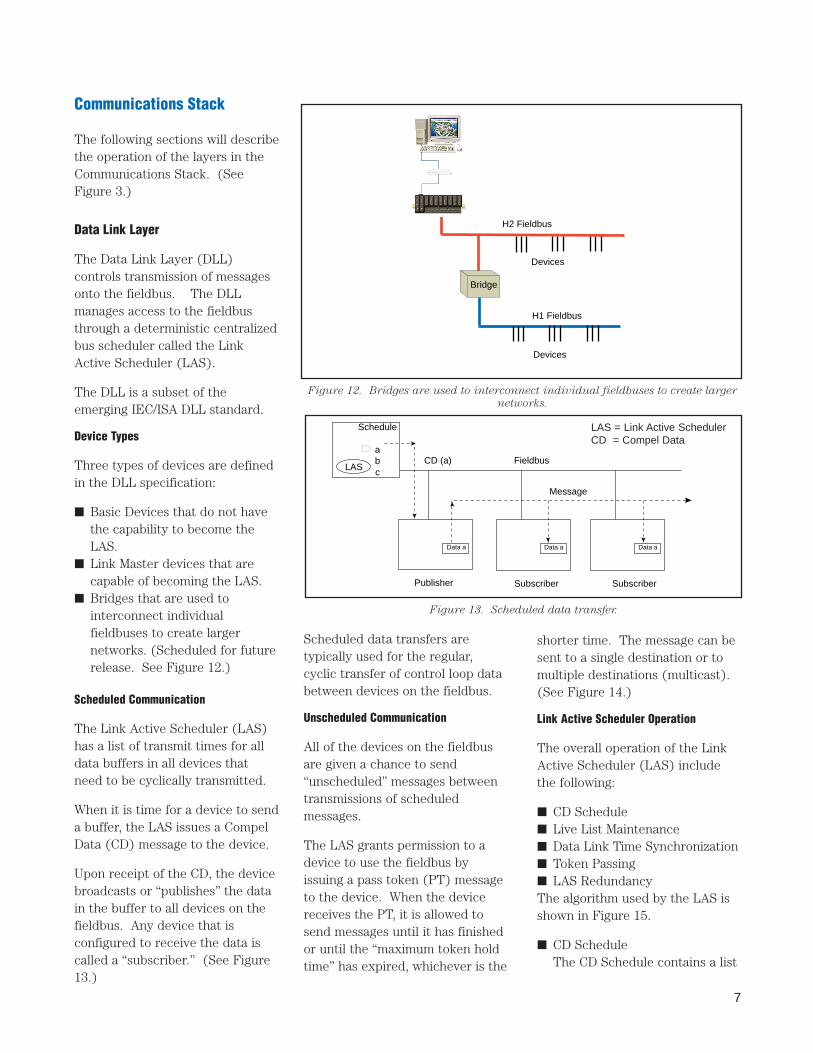
■ Bridges that are used tointerconnect individualfieldbuses to create largernetworks. (Scheduled for futurerelease. See Figure 12.)
Scheduled Communication
The Link Active Scheduler (LAS)has a list of transmit times for alldata buffers in all devices thatneed to be cyclically transmitted.
When it is time for a device to senda buffer, the LAS issues a CompelData (CD) message to the device.
Upon receipt of the CD, the devicebroadcasts or “publishes” the datain the buffer to all devices on thefieldbus. Any device that isconfigured to receive the data iscalled a “subscriber.” (See Figure13.)
Scheduled data transfers aretypically used for the regular,cyclic transfer of control loop databetween devices on the fieldbus.
Unscheduled Communication
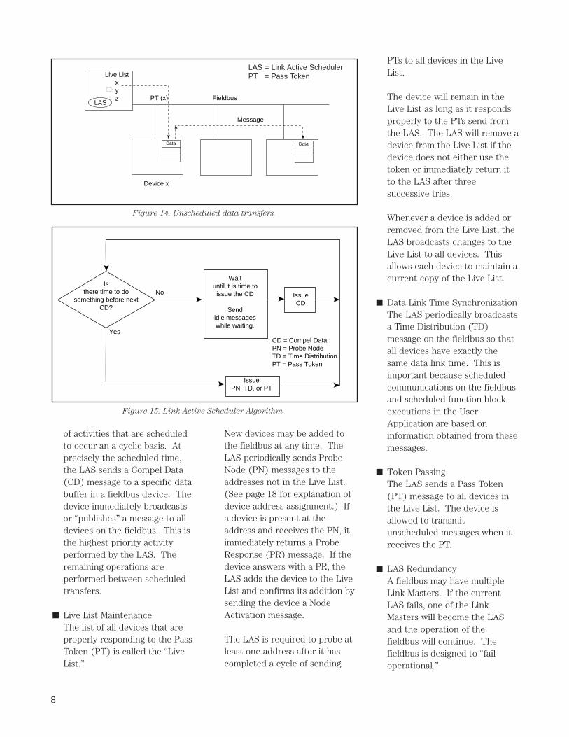
All of the devices on the fieldbusare given a chance to send“unscheduled” messages betweentransmissions of scheduledmessages.
The LAS grants permission to adevice to use the fieldbus byissuing a pass token (PT) messageto the device. When the devicereceives the PT, it is allowed tosend messages until it has finishedor until the “maximum token holdtime” has expired, whichever is the
shorter time. The message can besent to a single destination or tomultiple destinations (multicast).(See Figure 14.)
Link Active Scheduler Operation
The overall operation of the LinkActive Scheduler (LAS) includethe following:
■ CD Schedule■ Live List Maintenance■ Data Link Time Synchronization■ Token Passing■ LAS RedundancyThe algorithm used by the LAS isshown in Figure 15.
■ CD ScheduleThe CD Schedule contains a list
H2 Fieldbus
Devices
Bridge
Devices
H1 Fieldbus
Schedule
abcLAS
Message
Data a Data a Data a
FieldbusCD (a)
Publisher Subscriber Subscriber
Figure 12. Bridges are used to interconnect individual fieldbuses to create larger
networks.
Figure 13. Scheduled data transfer.
LAS = Link Active SchedulerCD = Compel Data
8
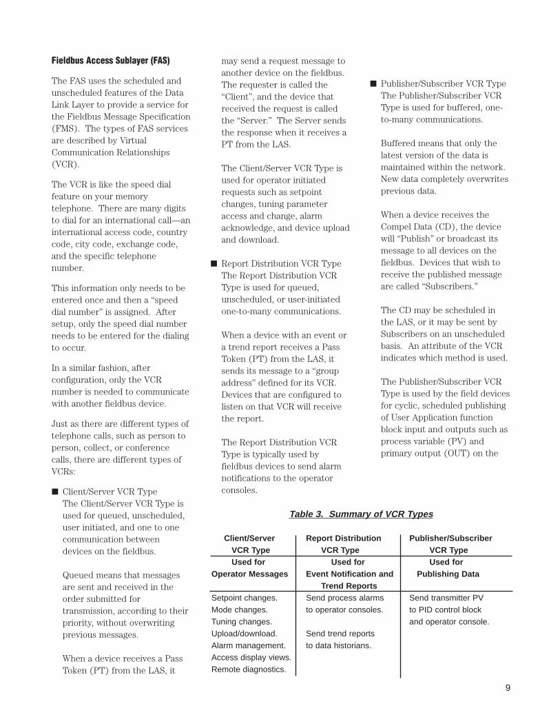
of activities that are scheduledto occur an a cyclic basis. Atprecisely the scheduled time,the LAS sends a Compel Data(CD) message to a specific databuffer in a fieldbus device. Thedevice immediately broadcastsor “publishes” a message to alldevices on the fieldbus. This isthe highest priority activityperformed by the LAS. Theremaining operations areperformed between scheduledtransfers.
■ Live List MaintenanceThe list of all devices that areproperly responding to the PassToken (PT) is called the “LiveList.”
New devices may be added tothe fieldbus at any time. TheLAS periodically sends ProbeNode (PN) messages to theaddresses not in the Live List.(See page 18 for explanation ofdevice address assignment.) Ifa device is present at theaddress and receives the PN, itimmediately returns a ProbeResponse (PR) message. If thedevice answers with a PR, theLAS adds the device to the LiveList and confirms its addition bysending the device a NodeActivation message.
The LAS is required to probe atleast one address after it hascompleted a cycle of sending
PTs to all devices in the LiveList.
The device will remain in theLive List as long as it respondsproperly to the PTs send fromthe LAS. The LAS will remove adevice from the Live List if thedevice does not either use thetoken or immediately return itto the LAS after threesuccessive tries.
Whenever a device is added orremoved from the Live List, theLAS broadcasts changes to theLive List to all devices. Thisallows each device to maintain acurrent copy of the Live List.
■ Data Link Time SynchronizationThe LAS periodically broadcastsa Time Distribution (TD)message on the fieldbus so thatall devices have exactly thesame data link time. This isimportant because scheduledcommunications on the fieldbusand scheduled function blockexecutions in the UserApplication are based oninformation obtained from thesemessages.
■ Token PassingThe LAS sends a Pass Token(PT) message to all devices inthe Live List. The device isallowed to transmitunscheduled messages when itreceives the PT.
■ LAS RedundancyA fieldbus may have multipleLink Masters. If the currentLAS fails, one of the LinkMasters will become the LASand the operation of thefieldbus will continue. Thefieldbus is designed to “failoperational.”
Live Listxyz
LAS
Message
FieldbusPT (x)
Device x
Data Data
Figure 14. Unscheduled data transfers.
Isthere time to do
something before nextCD?
No
Yes
Waituntil it is time to
issue the CD
Sendidle messageswhile waiting.
IssueCD
IssuePN, TD, or PT
CD = Compel DataPN = Probe NodeTD = Time DistributionPT = Pass Token
Figure 15. Link Active Scheduler Algorithm.
LAS = Link Active SchedulerPT = Pass Token
9
Fieldbus Access Sublayer (FAS)
The FAS uses the scheduled andunscheduled features of the DataLink Layer to provide a service forthe Fieldbus Message Specification(FMS). The types of FAS servicesare described by VirtualCommunication Relationships(VCR).
The VCR is like the speed dialfeature on your memorytelephone. There are many digitsto dial for an international call—aninternational access code, countrycode, city code, exchange code,and the specific telephonenumber.
This information only needs to beentered once and then a “speeddial number” is assigned. Aftersetup, only the speed dial numberneeds to be entered for the dialingto occur.
In a similar fashion, afterconfiguration, only the VCRnumber is needed to communicatewith another fieldbus device.
Just as there are different types oftelephone calls, such as person toperson, collect, or conferencecalls, there are different types ofVCRs:
■ Client/Server VCR TypeThe Client/Server VCR Type isused for queued, unscheduled,user initiated, and one to onecommunication betweendevices on the fieldbus.
Queued means that messagesare sent and received in theorder submitted fortransmission, according to theirpriority, without overwritingprevious messages.
When a device receives a PassToken (PT) from the LAS, it
may send a request message toanother device on the fieldbus.The requester is called the“Client”, and the device thatreceived the request is calledthe “Server.” The Server sendsthe response when it receives aPT from the LAS.
The Client/Server VCR Type isused for operator initiatedrequests such as setpointchanges, tuning parameteraccess and change, alarmacknowledge, and device uploadand download.
■ Report Distribution VCR TypeThe Report Distribution VCRType is used for queued,unscheduled, or user-initiatedone-to-many communications.
When a device with an event ora trend report receives a PassToken (PT) from the LAS, itsends its message to a “groupaddress” defined for its VCR.Devices that are configured tolisten on that VCR will receivethe report.
The Report Distribution VCRType is typically used byfieldbus devices to send alarmnotifications to the operatorconsoles.
■ Publisher/Subscriber VCR TypeThe Publisher/Subscriber VCRType is used for buffered, one-to-many communications.
Buffered means that only thelatest version of the data ismaintained within the network.New data completely overwritesprevious data.
When a device receives theCompel Data (CD), the devicewill “Publish” or broadcast itsmessage to all devices on thefieldbus. Devices that wish toreceive the published messageare called “Subscribers.”
The CD may be scheduled inthe LAS, or it may be sent bySubscribers on an unscheduledbasis. An attribute of the VCRindicates which method is used.
The Publisher/Subscriber VCRType is used by the field devicesfor cyclic, scheduled publishingof User Application functionblock input and outputs such asprocess variable (PV) andprimary output (OUT) on the
Table 3. Summary of VCR T ypes
Client/Server Report Distribution Publisher/SubscriberVCR Type VCR Type VCR TypeUsed for Used for Used for
Operator Messages Event Notification and Publishing DataTrend Reports
Setpoint changes. Send process alarms Send transmitter PVMode changes. to operator consoles. to PID control blockTuning changes. and operator console.Upload/download. Send trend reportsAlarm management. to data historians.Access display views.Remote diagnostics.
10
fieldbus.
Fieldbus Message Specification(FMS)
Fieldbus Message Specification(FMS) services allow userapplications to send messages toeach other across the fieldbususing a standard set of messageformats.
FMS describes the communicationservices, message formats, andprotocol behavior needed to buildmessages for the User Application.(See Figure 16.)
Data that is communicated overthe fieldbus is described by an“object description.” Objectdescriptions are collected togetherin a structure called an “objectdictionary” (OD). (See Figure17.)
The object description is identifiedby its index in the OD. Index 0,called the object dictionaryheader, provides a description ofthe dictionary itself and definesthe first index for the objectdescriptions of the UserApplication. The User Applicationobject descriptions can start at anyindex above 255.
Index 255 and below definestandard data types such asboolean, integer, float, bitstring,and data structures that are usedto build all other objectdescriptions.
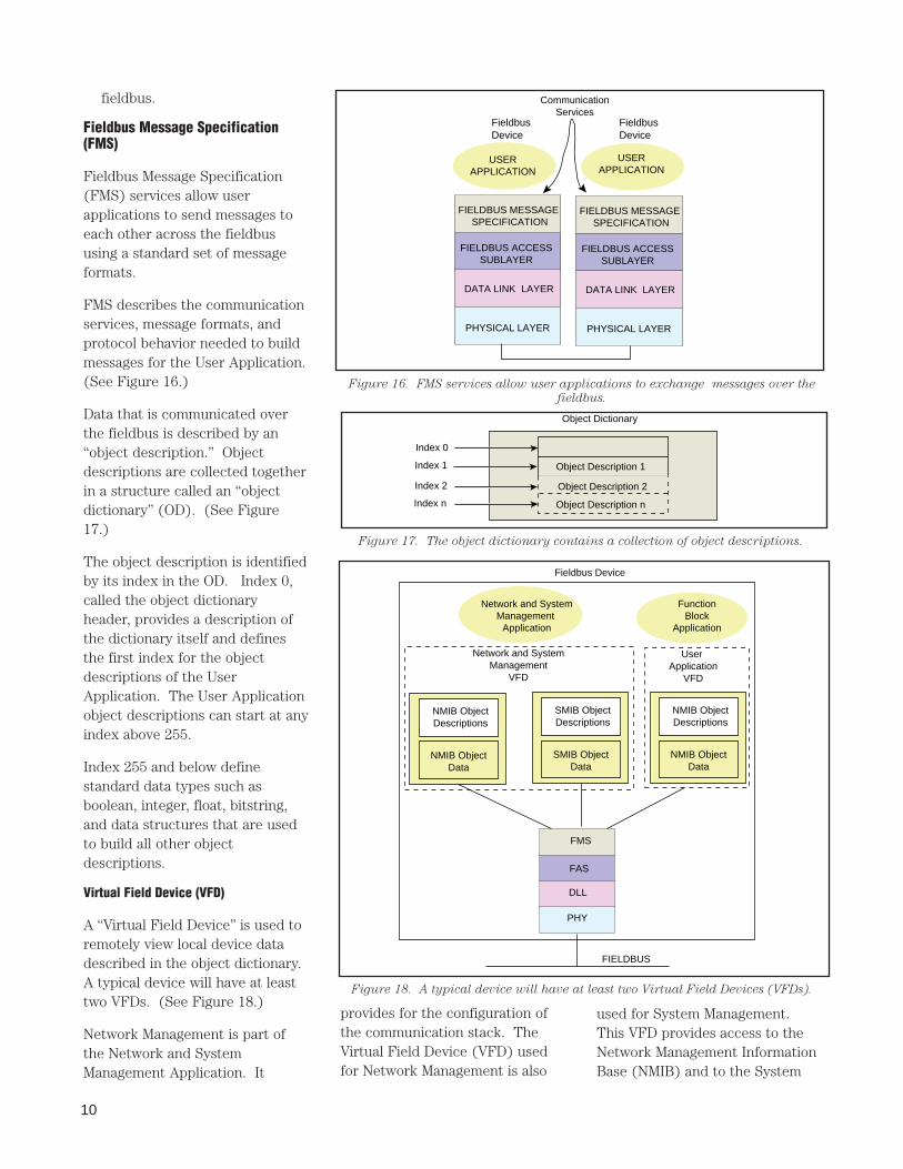
Virtual Field Device (VFD)
A “Virtual Field Device” is used toremotely view local device datadescribed in the object dictionary.A typical device will have at leasttwo VFDs. (See Figure 18.)
Network Management is part ofthe Network and SystemManagement Application. It
USERAPPLICATION
FIELDBUS MESSAGE SPECIFICATION
FIELDBUS ACCESSSUBLAYER
DATA LINK LAYER
PHYSICAL LAYER
USERAPPLICATION
FieldbusDevice
FieldbusDevice
CommunicationServices
FIELDBUS MESSAGE SPECIFICATION
FIELDBUS ACCESSSUBLAYER
DATA LINK LAYER
PHYSICAL LAYER
Figure 16. FMS services allow user applications to exchange messages over the
fieldbus.
Object Dictionary
Object Description 1
Object Description 2
Object Description n
Index 0
Index 1
Index 2
Index n
Figure 17. The object dictionary contains a collection of object descriptions.
FMS
Network and SystemManagement
Application
FAS
DLL
PHY
FunctionBlock
Application
NMIB ObjectDescriptions
NMIB ObjectData
SMIB ObjectDescriptions
SMIB ObjectData
Network and SystemManagement
VFD
User Application
VFD
NMIB ObjectDescriptions
NMIB ObjectData
FIELDBUS
Fieldbus Device
Figure 18. A typical device will have at least two Virtual Field Devices (VFDs).
provides for the configuration ofthe communication stack. TheVirtual Field Device (VFD) usedfor Network Management is also
used for System Management.This VFD provides access to theNetwork Management InformationBase (NMIB) and to the System
11
Management Information Base(SMIB). NMIB data includesVirtual CommunicationRelationships (VCR), dynamicvariables, statistics, and LinkActive Schedule (LAS) schedules(if the device is a Link Master).SMIB data includes device tag andaddress information, and schedulesfor function block execution.
System Management is describedfurther in the User ApplicationSection.
Communication Services
FMS communication servicesprovide a standardized way foruser applications such as functionblocks to communicate over thefieldbus. Specific FMScommunication services aredefined for each object type.
All of the FMS services can useonly the Client Server VCR Typeexcept as noted.
Communications Services includethe following:
■ Context Management ServicesThe following FMS services areused to establish and releaseVirtual CommunicationRelationships (VCR) with, anddetermine the status of, a VFD.● Initiate
Establish Communications
● Abort
Release communications
● Reject
Reject improper service
● Status
Read a device status
● UnsolicitedStatus
Send unsolicited status● Identify
Read vendor, type and version
■ Object Dictionary ServicesThe following FMS servicesallow the User Application toaccess and change the objectdescriptions (OD) in a VFD.
● GetOD
Read an object dictionary (OD)● InitiatePutOD
Start an OD Load● PutOD
Load an OD into a device● TerminatePutOD
Stop an OD Load
■ Variable Access ServicesThe following FMS servicesallow the user application toaccess and change variablesassociated with an objectdescription.● Read
Read a variable● Write
Write a variable● InformationReport
Send Data*● DefineVariableList
Define a Variable List● DeleteVariableList
Delete a Variable List* Can use Publisher/Subscriber or
Report Distribution VCR Types.
■ Event ServicesThe following FMS servicesallow the user application toreport events and manage eventprocessing.
● EventNotification
Report an event*● AcknowledgeEventNotification
Acknowledge an event● AlterEventConditionMonitoring
Disable/Enable event** Can use Report Distribution VCR
Type.
■ Upload/Download ServicesIt is often necessary to remotelyupload or download data andprograms over the fieldbus,especially for more complexdevices such as programmablelogic controllers.
To allow uploads and downloadsusing the FMS service, a“Domain” is used. A Domainrepresents a memory space in adevice.
The following FMS servicesallow the User Application toupload and download a Domainin a remote device.● RequestDomainUpload
Request Upload
● InitiateUploadSequence
Open Upload
● UploadSegment
Read data from device
● TerminateUploadSequence
Stop Upload
● RequestDomainDownload
Request Download
● InitiateDownloadSequence
Open Download
● DownloadSegment
Send data to device
● TerminateDownloadSequence
Stop Download
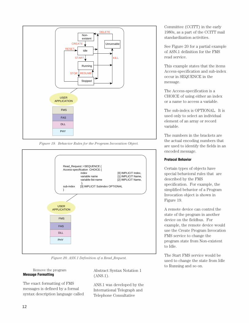
■ Program Invocation ServicesThe “Program Invocation” (PI)allows the execution of aprogram in one device to becontrolled remotely.
A device could download aprogram into a Domain ofanother device using thedownload service and thenremotely operate the programby issuing PI service requests.
The state diagram for the PI isshown as an example of FMSprotocol in Figure 19.● CreateProgramInvocation
Create a program object
● DeleteProgramInvocation
Delete a program object
● Start
Start a program
● Stop
Stop a program
● Resume
Resume program execution
● Reset
Reset the program
● Kill
12
Remove the programMessage Formatting
The exact formatting of FMSmessages is defined by a formalsyntax description language called
Read_Request::=SEQUENCE {Access-specification CHOICE { index [0] IMPLICIT Index, variable name [1] IMPLICIT Name, variable-list-name [2] IMPLICIT Name, },sub-index [3] IMPLICIT Subindex OPTIONAL}
FMS
FAS
DLL
PHY
USERAPPLICATION
Figure 20. ASN.1 Definition of a Read_Request.
FMS
FAS
DLL
PHY
USERAPPLICATION
Non-existent
Idle
Running
Stopped
UnrunnableCREATE
DELETE
RESET
STOP RESUME
START KILL
Figure 19. Behavior Rules for the Program Invocation Object.
Committee (CCITT) in the early1980s, as a part of the CCITT mailstandardization activities.
See Figure 20 for a partial exampleof ASN.1 definition for the FMSread service.
This example states that the itemsAccess-specification and sub-indexoccur in SEQUENCE in themessage.
The Access-specification is aCHOICE of using either an indexor a name to access a variable.
The sub-index is OPTIONAL. It isused only to select an individualelement of an array or recordvariable.
The numbers in the brackets arethe actual encoding numbers thatare used to identify the fields in anencoded message.
Protocol Behavior
Certain types of objects havespecial behavioral rules that aredescribed by the FMSspecification. For example, thesimplified behavior of a ProgramInvocation object is shown inFigure 19.
A remote device can control thestate of the program in anotherdevice on the fieldbus. Forexample, the remote device woulduse the Create Program InvocationFMS service to change theprogram state from Non-existentto Idle.
The Start FMS service would beused to change the state from Idleto Running and so on.
Abstract Syntax Notation 1(ANS.1).
ANS.1 was developed by theInternational Telegraph andTelephone Consultative
13
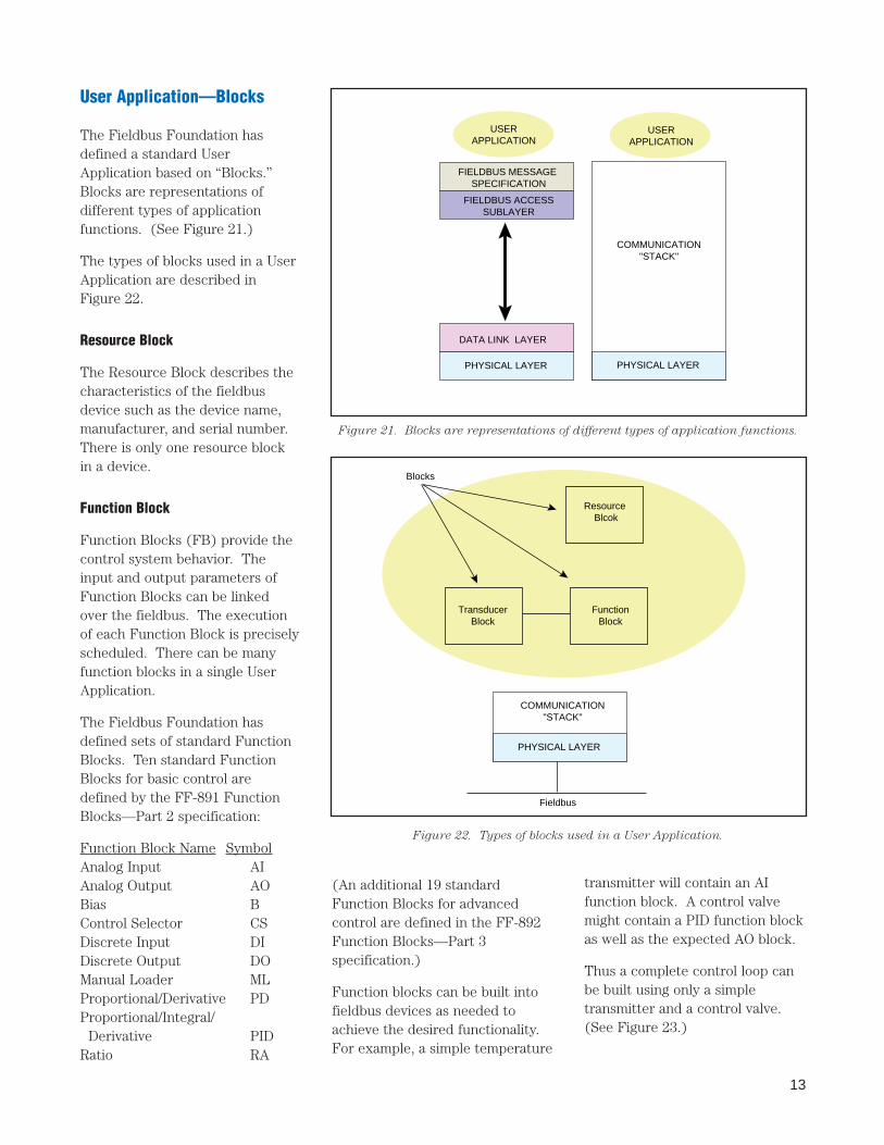
User Application—Blocks
The Fieldbus Foundation hasdefined a standard UserApplication based on “Blocks.”Blocks are representations ofdifferent types of applicationfunctions. (See Figure 21.)
The types of blocks used in a UserApplication are described inFigure 22.
Resource Block
The Resource Block describes thecharacteristics of the fieldbusdevice such as the device name,manufacturer, and serial number.There is only one resource blockin a device.
Function Block
Function Blocks (FB) provide thecontrol system behavior. Theinput and output parameters ofFunction Blocks can be linkedover the fieldbus. The executionof each Function Block is preciselyscheduled. There can be manyfunction blocks in a single UserApplication.
The Fieldbus Foundation hasdefined sets of standard FunctionBlocks. Ten standard FunctionBlocks for basic control aredefined by the FF-891 FunctionBlocks—Part 2 specification:
Function Block Name SymbolAnalog Input AIAnalog Output AOBias BControl Selector CSDiscrete Input DIDiscrete Output DOManual Loader MLProportional/Derivative PDProportional/Integral/
Derivative PIDRatio RA
(An additional 19 standardFunction Blocks for advancedcontrol are defined in the FF-892Function Blocks—Part 3specification.)
Function blocks can be built intofieldbus devices as needed toachieve the desired functionality.For example, a simple temperature
USERAPPLICATION
USERAPPLICATION
FIELDBUS MESSAGE SPECIFICATION
FIELDBUS ACCESSSUBLAYER
DATA LINK LAYER
PHYSICAL LAYER PHYSICAL LAYER
COMMUNICATION"STACK"
PHYSICAL LAYER
COMMUNICATION"STACK"
Resource Blcok
FunctionBlock
TransducerBlock
Blocks
Fieldbus
Figure 21. Blocks are representations of different types of application functions.
Figure 22. Types of blocks used in a User Application.
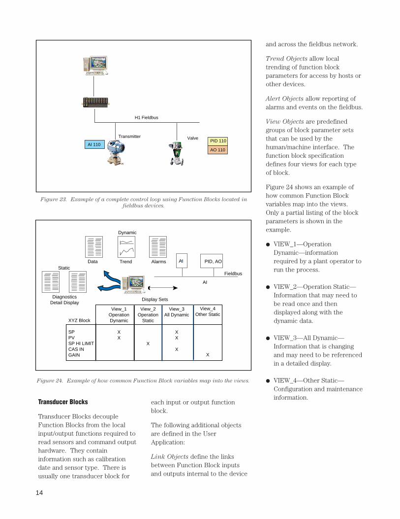
transmitter will contain an AIfunction block. A control valvemight contain a PID function blockas well as the expected AO block.
Thus a complete control loop canbe built using only a simpletransmitter and a control valve.(See Figure 23.)
14
Transducer Blocks
Transducer Blocks decoupleFunction Blocks from the localinput/output functions required toread sensors and command outputhardware. They containinformation such as calibrationdate and sensor type. There isusually one transducer block for
and across the fieldbus network.
Trend Objects allow localtrending of function blockparameters for access by hosts orother devices.
Alert Objects allow reporting ofalarms and events on the fieldbus.
View Objects are predefinedgroups of block parameter setsthat can be used by thehuman/machine interface. Thefunction block specificationdefines four views for each typeof block.
Figure 24 shows an example ofhow common Function Blockvariables map into the views.Only a partial listing of the blockparameters is shown in theexample.
● VIEW_1—OperationDynamic—informationrequired by a plant operator torun the process.
● VIEW_2—Operation Static—Information that may need tobe read once and thendisplayed along with thedynamic data.
● VIEW_3—All Dynamic—Information that is changingand may need to be referencedin a detailed display.
● VIEW_4—Other Static—Configuration and maintenanceinformation.
H1 Fieldbus
Transmitter Valve
AI 110PID 110
AO 110
Figure 23. Example of a complete control loop using Function Blocks located in
fieldbus devices.
Data Trend AlarmsStatic
DiagnosticsDetail Display
AI PID, AO
Fieldbus
AI
View_1OperationDynamic
XX
View_2Operation
Static
X
View_3All Dynamic
XX
X
View_4Other Static
X
XYZ Block
SPPVSP HI LIMITCAS INGAIN
Display Sets
Dynamic
Figure 24. Example of how common Function Block variables map into the views.
each input or output functionblock.
The following additional objectsare defined in the UserApplication:
Link Objects define the linksbetween Function Block inputsand outputs internal to the device
15
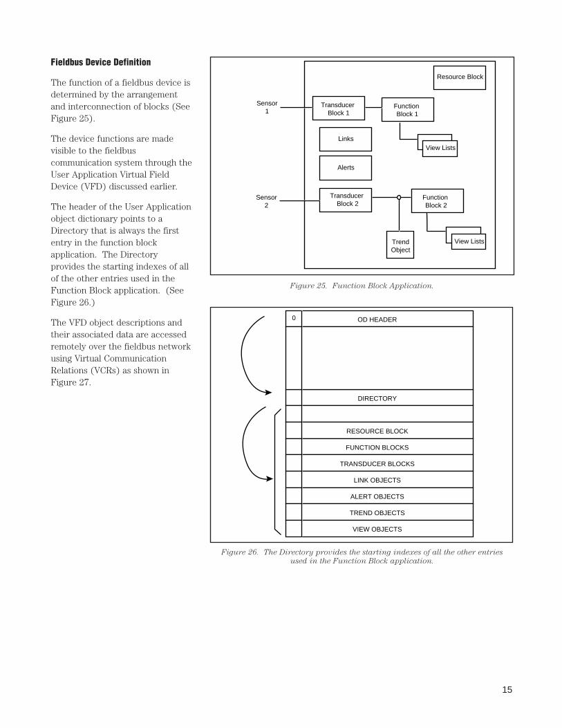
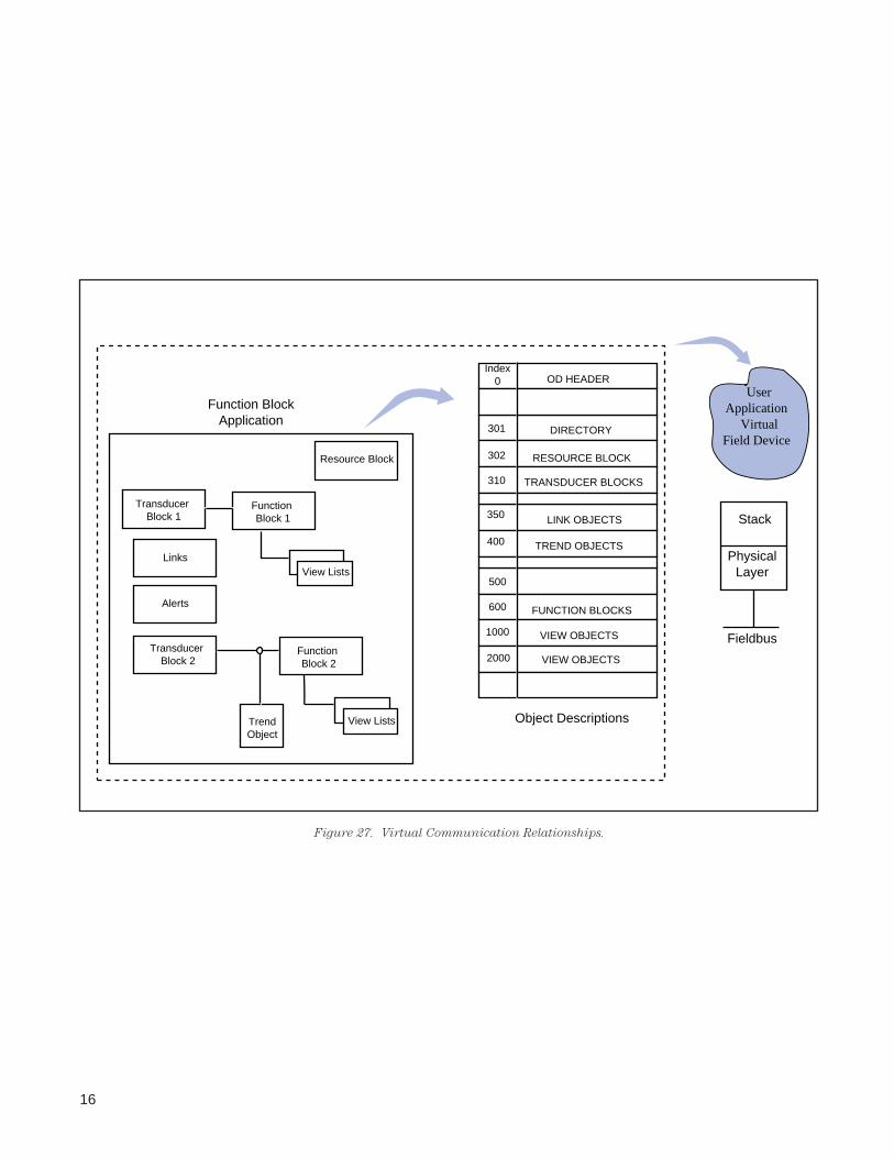
Fieldbus Device Definition
The function of a fieldbus device isdetermined by the arrangementand interconnection of blocks (SeeFigure 25).
The device functions are madevisible to the fieldbuscommunication system through theUser Application Virtual FieldDevice (VFD) discussed earlier.
The header of the User Applicationobject dictionary points to aDirectory that is always the firstentry in the function blockapplication. The Directoryprovides the starting indexes of allof the other entries used in theFunction Block application. (SeeFigure 26.)
The VFD object descriptions andtheir associated data are accessedremotely over the fieldbus networkusing Virtual CommunicationRelations (VCRs) as shown inFigure 27.
Transducer Block 1
Links
Alerts
Transducer Block 2
Function Block 1
Function Block 2
TrendObject
Resource Block
Sensor1
Sensor2
View Lists
View Lists
Figure 25. Function Block Application.
OD HEADER
DIRECTORY
RESOURCE BLOCK
FUNCTION BLOCKS
TRANSDUCER BLOCKS
LINK OBJECTS
ALERT OBJECTS
TREND OBJECTS
VIEW OBJECTS
0
Figure 26. The Directory provides the starting indexes of all the other entries
used in the Function Block application.
16
Transducer Block 1
Links
Alerts
Transducer Block 2
Function Block 1
Function Block 2
TrendObject
Resource Block
View Lists
View Lists
OD HEADER
DIRECTORY
RESOURCE BLOCK
FUNCTION BLOCKS
TRANSDUCER BLOCKS
LINK OBJECTS
TREND OBJECTS
VIEW OBJECTS
Index0
FUNCTION BLOCKS
VIEW OBJECTS
301
302
310
350
400
500
600
1000
2000
Object Descriptions
Function BlockApplication
Fieldbus
PhysicalLayer
Stack
UserApplication
VirtualField Device
Figure 27. Virtual Communication Relationships.
17
System Management
Function Blocks must execute atprecisely defined intervals and inthe proper sequence of correctcontrol system operation.
System management synchronizesexecution of the Function Blocksand the communication of functionblock parameters on the fieldbus.
System management also handlesother important system featuressuch as publication of the time ofday to all devices, includingautomatic switchover to aredundant time publisher,automatic assignment of deviceaddresses, and searching forparameter names or “tags” on thefieldbus.
All of the configurationinformation needed by SystemManagement, such as the FunctionBlock schedule, is described byobject descriptions in the Networkand System Management VirtualField Device (VFD) in each device.This VFD provides access to theSystem Management InformationBase (SMIB) and also to theNetwork Management InformationBase (NMIB).
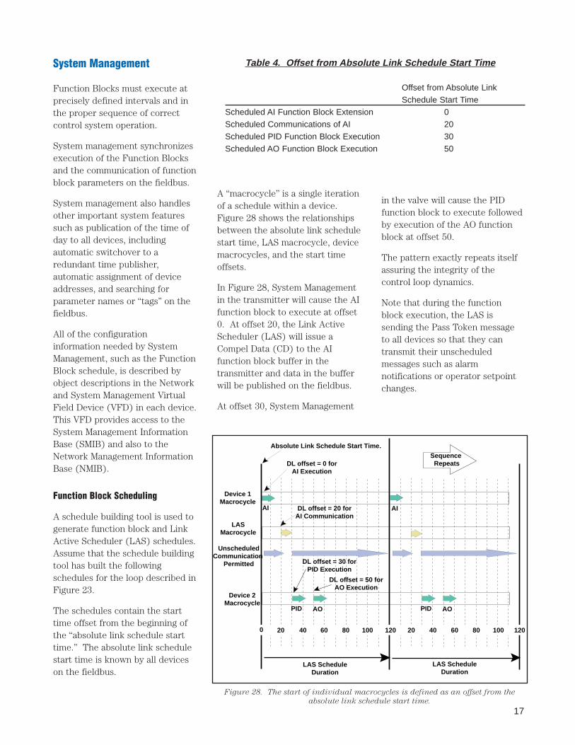
Function Block Scheduling
A schedule building tool is used togenerate function block and LinkActive Scheduler (LAS) schedules.Assume that the schedule buildingtool has built the followingschedules for the loop described inFigure 23.
The schedules contain the starttime offset from the beginning ofthe “absolute link schedule starttime.” The absolute link schedulestart time is known by all deviceson the fieldbus.
A “macrocycle” is a single iterationof a schedule within a device.Figure 28 shows the relationshipsbetween the absolute link schedulestart time, LAS macrocycle, devicemacrocycles, and the start timeoffsets.
In Figure 28, System Managementin the transmitter will cause the AIfunction block to execute at offset0. At offset 20, the Link ActiveScheduler (LAS) will issue aCompel Data (CD) to the AIfunction block buffer in thetransmitter and data in the bufferwill be published on the fieldbus.
At offset 30, System Management
in the valve will cause the PIDfunction block to execute followedby execution of the AO functionblock at offset 50.
The pattern exactly repeats itselfassuring the integrity of thecontrol loop dynamics.
Note that during the functionblock execution, the LAS issending the Pass Token messageto all devices so that they cantransmit their unscheduledmessages such as alarmnotifications or operator setpointchanges.
Table 4. Of fset from Absolute Link Schedule Start T ime
Offset from Absolute LinkSchedule Start Time
Scheduled AI Function Block Extension 0Scheduled Communications of AI 20Scheduled PID Function Block Execution 30Scheduled AO Function Block Execution 50
Device 1Macrocycle
LASMacrocycle
UnscheduledCommunication
Permitted
Device 2Macrocycle
AIDL offset = 20 forAI Communication
Sequence Repeats
AI
Absolute Link Schedule Start Time.
DL offset = 0 forAI Execution
DL offset = 30 forPID Execution
DL offset = 50 forAO Execution
PID AO PID AO
0 20 40 60 80 100 120 20 40 60 80 100 120
LAS ScheduleDuration
LAS ScheduleDuration
Figure 28. The start of individual macrocycles is defined as an offset from the
absolute link schedule start time.
18
For this example, the only timethat the fieldbus can not be usedfor unscheduled messages is fromoffset 20 to offset 30 when the AIfunction block data is beingpublished on the fieldbus.
Application Clock Distribution
The FOUNDATION Fieldbus supportsan application clock distributionfunction. The application clock isusually set to the local time of dayor to Universal Coordinated Time.
System Management has a timepublisher that periodically sendsan application clocksynchronization message to allfieldbus devices. The data linkscheduling time is sampled andsent with the application clockmessage so that the receivingdevices can adjust their localapplication time. Betweensynchronization messages,application clock time isindependently maintained in eachdevice based on its own internalclock.
Application clock synchronizationallows the devices to time stampdata throughout the fieldbusnetwork. If there are backupapplication clock publishers on thefieldbus, a backup publisher will
become active if the currentlyactive time publisher should fail.
Device Address Assignment
Every fieldbus device must have aunique network address andphysical device tag for the fieldbusto operate properly.
To avoid the need for addressswitches on the instruments,assignment of network addressescan be performed automatically bySystem Management.
The sequence for assigning anetwork address to a new device isas follows:
■ A physical device tag is assignedto a new device via aconfiguration device. This canbe done “off-line” at a bench or“on-line” through special defaultnetwork addresses on thefieldbus.
■ Using default networkaddresses, System Managementasks the device for its physicaldevice tag. System Managementuses the physical device tag tolook up the new networkaddress in a configuration table.System Management then sendsa special “set address” message
to the device that forces thedevice to move to the newnetwork address.
■ The sequence is repeated forall devices that enter thenetwork at a default address.
Find Tag Service
For the convenience of hostsystems and portablemaintenance devices, SystemManagement supports a servicefor finding devices or variables bya tag search.
The “find tag query” message isbroadcast to all fieldbus devices.Upon receipt of the message, eachdevice searches its Virtual FieldDevices (VFD) for the requestedtag and returns complete pathinformation (if the tag is found)including the network address,VFD number, virtualcommunication relationship(VCR) index, and objectdictionary (OD) index. Once thepath is known, the host ormaintenance device can accessthe data for the tag.
19
Device Descriptions
A critical characteristic required offieldbus devices is interoperability.To achieve interoperability, DeviceDescription (DD) technology isused in addition to standardfunction block parameter andbehavior definitions.
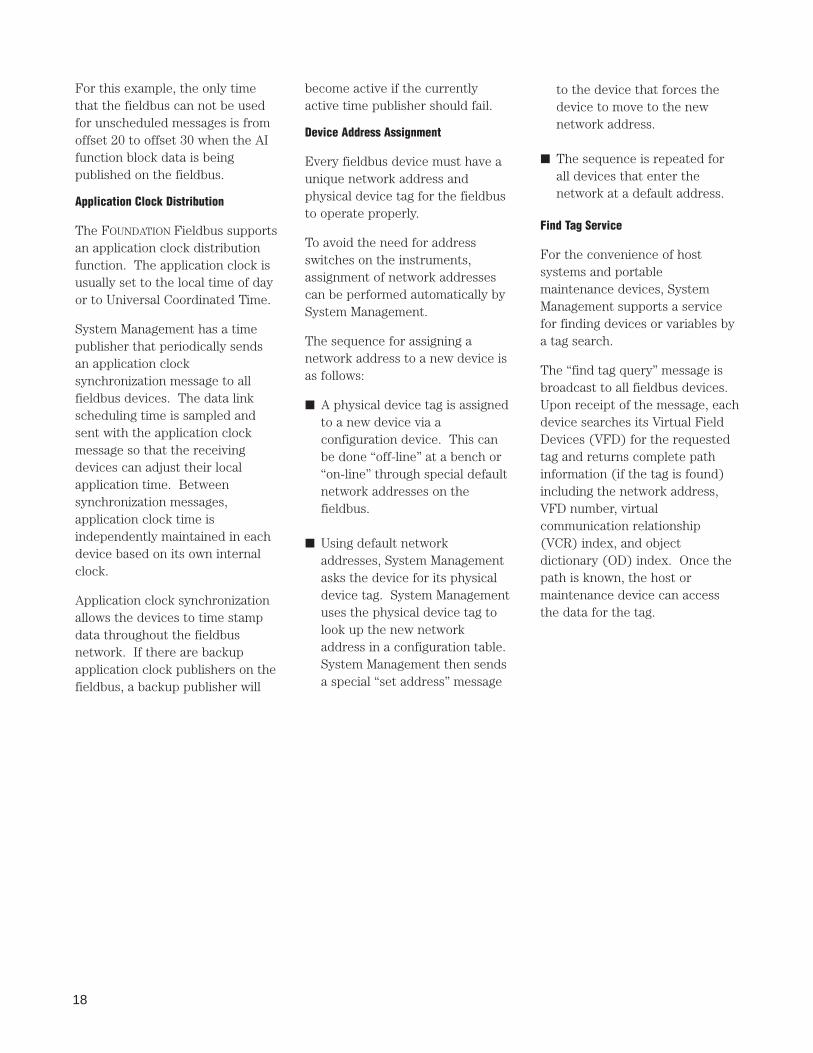
The DD provides an extendeddescription of each object in theVirtual Field Device (VFD) asshown in Figure 29.
The DD provides informationneeded for a control system or hostto understand the meaning of datain the VFD, including the humaninterface for functions such ascalibration and diagnostics. Thisthe DD can be thought of as a“driver” for the device.
The DDs are similar to the driversthat your personal computer (PC)uses to operate different printersand other devices that areconnected to the PC. Anyfieldbus-capable control system orhost can operate with the device ifit has the device’s DD.
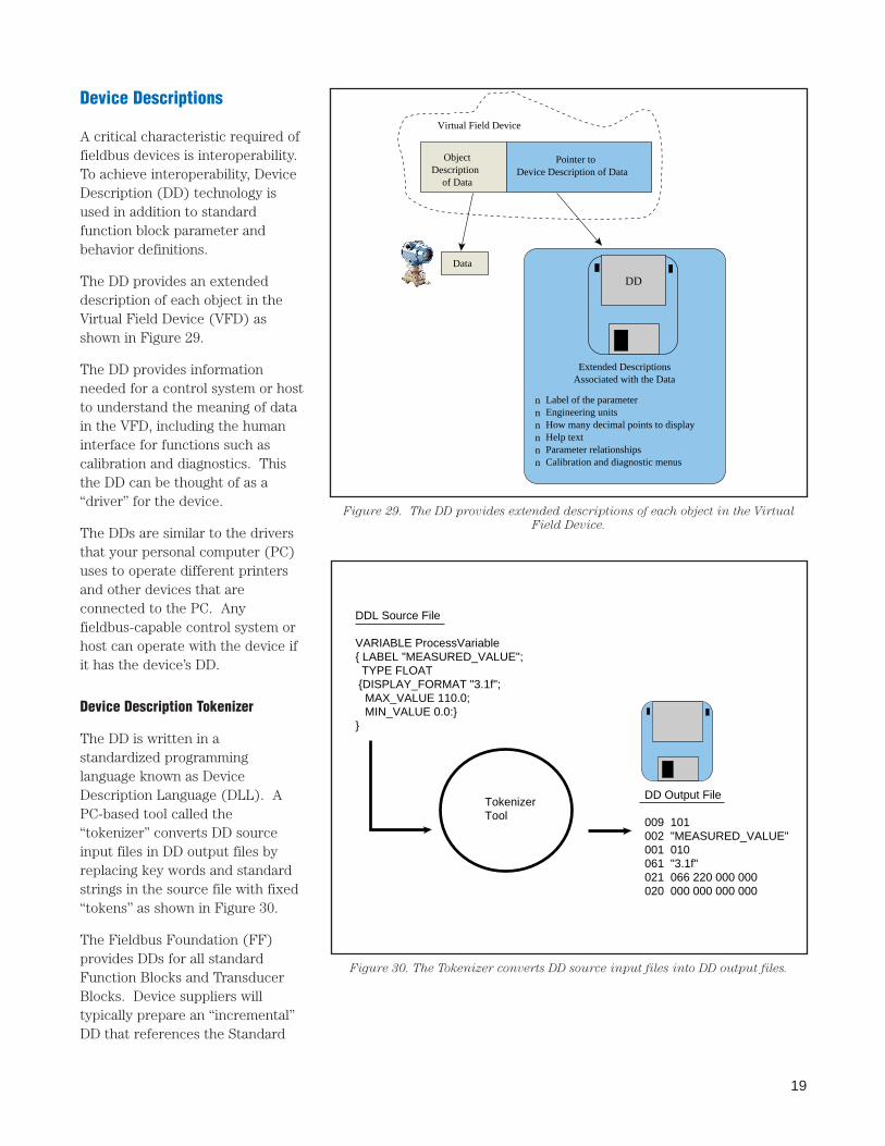
Device Description Tokenizer
The DD is written in astandardized programminglanguage known as DeviceDescription Language (DLL). APC-based tool called the“tokenizer” converts DD sourceinput files in DD output files byreplacing key words and standardstrings in the source file with fixed“tokens” as shown in Figure 30.
The Fieldbus Foundation (FF)provides DDs for all standardFunction Blocks and TransducerBlocks. Device suppliers willtypically prepare an “incremental”DD that references the Standard
Data
ObjectDescription
of Data
Pointer to Device Description of Data
Virtual Field Device
Extended DescriptionsAssociated with the Data
Label of the parameterEngineering unitsHow many decimal points to displayHelp textParameter relationshipsCalibration and diagnostic menus
nnnnnn
DD
DD Output File
009 101002 "MEASURED_VALUE"001 010061 "3.1f"021 066 220 000 000020 000 000 000 000
DDL Source File
VARIABLE ProcessVariable{ LABEL "MEASURED_VALUE"; TYPE FLOAT {DISPLAY_FORMAT "3.1f"; MAX_VALUE 110.0; MIN_VALUE 0.0:}}
TokenizerTool
Figure 29. The DD provides extended descriptions of each object in the Virtual
Field Device.
Figure 30. The Tokenizer converts DD source input files into DD output files.
20
DDs. Suppliers may also addsupplier specific features such ascalibration and diagnosticprocedures to their devices. Thesefeatures can also be described inthe incremental DD.
The Fieldbus Foundation makesthe Standard DDs available on aCD-ROM. The user can obtain theincremental DD from the devicesupplier or from the FieldbusFoundation if the supplier hasregistered their incremental DDwith the Fieldbus Foundation.
The incremental DDs can also beread directly from the device overthe fieldbus, if the device supportsthe upload services and contains aVirtual Field Device (VFD) for theDD.
New devices are added to thefieldbus by simply connecting thedevice to the fieldbus wire andproviding the control system orhost with the standard andincremental (if any) DD for thenew device.
Fisher-Rosemount supplies theDDs for all of the fieldbus devicesit manufactures. Additionally, theDeltaV control system and theAMS Fieldbus Device Configuratorsoftware also supply DDs for alldevices currently available—regardless of manufacturer.
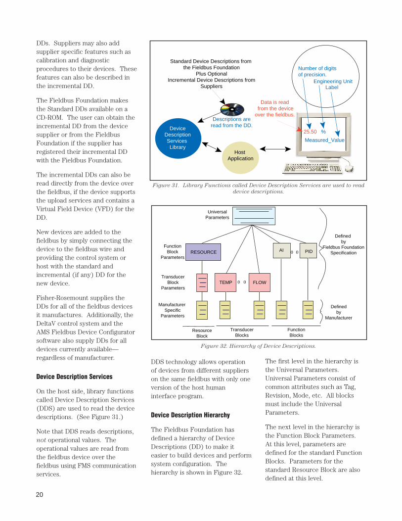
Device Description Services
On the host side, library functionscalled Device Description Services(DDS) are used to read the devicedescriptions. (See Figure 31.)
Note that DDS reads descriptions,not operational values. Theoperational values are read fromthe fieldbus device over thefieldbus using FMS communicationservices.
DDS technology allows operationof devices from different supplierson the same fieldbus with only oneversion of the host humaninterface program.
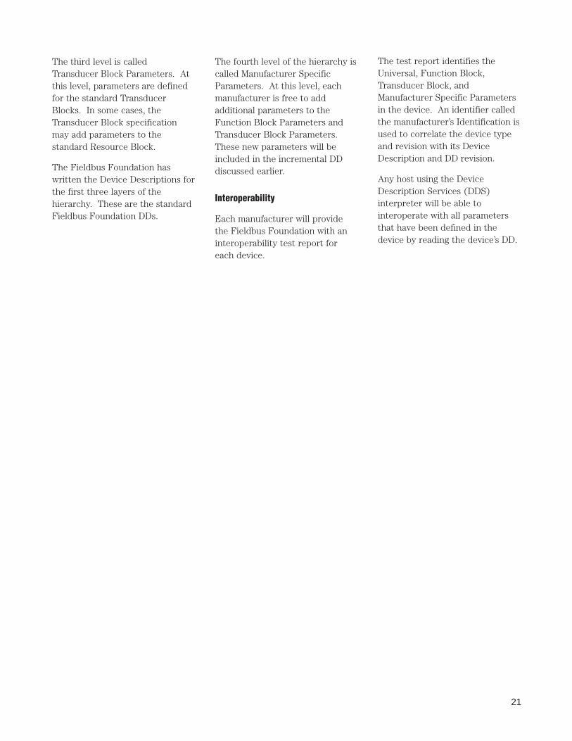
Device Description Hierarchy
The Fieldbus Foundation hasdefined a hierarchy of DeviceDescriptions (DD) to make iteasier to build devices and performsystem configuration. Thehierarchy is shown in Figure 32.
The first level in the hierarchy isthe Universal Parameters.Universal Parameters consist ofcommon attributes such as Tag,Revision, Mode, etc. All blocksmust include the UniversalParameters.
The next level in the hierarchy isthe Function Block Parameters.At this level, parameters aredefined for the standard FunctionBlocks. Parameters for thestandard Resource Block are alsodefined at this level.
Standard Device Descriptions from the Fieldbus Foundation
Plus OptionalIncremental Device Descriptions from
Suppliers
Host Application
DeviceDescriptionServices Library
Descriptions areread from the DD.
25.50 %
Measured_Value
Data is read from the deviceover the fieldbus.
Number of digitsof precision.
LabelEngineering Unit
Figure 31. Library Functions called Device Description Services are used to read
device descriptions.
UniversalParameters
FunctionBlock
Parameters
TransducerBlock
Parameters
Manufacturer Specific
Parameters
RESOURCE
TEMP FLOW0 0
AI PID0 0
ResourceBlock
TransducerBlocks
FunctionBlocks
Defined by
Fieldbus FoundationSpecification
Definedby
Manufacturer
Figure 32. Hierarchy of Device Descriptions.
21
The third level is calledTransducer Block Parameters. Atthis level, parameters are definedfor the standard TransducerBlocks. In some cases, theTransducer Block specificationmay add parameters to thestandard Resource Block.
The Fieldbus Foundation haswritten the Device Descriptions forthe first three layers of thehierarchy. These are the standardFieldbus Foundation DDs.
The fourth level of the hierarchy iscalled Manufacturer SpecificParameters. At this level, eachmanufacturer is free to addadditional parameters to theFunction Block Parameters andTransducer Block Parameters.These new parameters will beincluded in the incremental DDdiscussed earlier.
Interoperability
Each manufacturer will providethe Fieldbus Foundation with aninteroperability test report foreach device.
The test report identifies theUniversal, Function Block,Transducer Block, andManufacturer Specific Parametersin the device. An identifier calledthe manufacturer’s Identification isused to correlate the device typeand revision with its DeviceDescription and DD revision.
Any host using the DeviceDescription Services (DDS)interpreter will be able tointeroperate with all parametersthat have been defined in thedevice by reading the device’s DD.
22
System Configuration
Fieldbus system configurationconsists of two phases:
■ System Design■ Device Configuration
System Design
The system design for fieldbus-based systems is very similar totoday’s Distributed ControlSystems (DCS) design with thefollowing differences.
The first difference is in thephysical wiring due to the changefrom 4-20 mA analog point-to-pointsignal to a digital signal. The samephysical wire used today for 4-20mA signals can be reused forfieldbus, but with fieldbus manydevices can now be multidroppedto one wire. (See Figure 8.)
Each device on the fieldbus musthave a unique physical device tagand a corresponding networkaddress.
The second difference is the abilityto distribute some of the controland input/output (I/O) subsystemfunctions from the control systemto the fieldbus devices. This mayreduce the number of rackmounted controllers and remotemounted I/O equipment needed forthe system design.
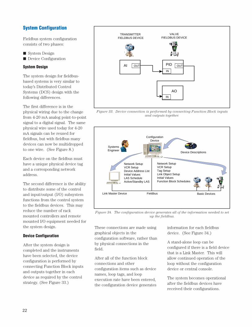
Device Configuration
After the system design iscompleted and the instrumentshave been selected, the deviceconfiguration is performed byconnecting Function Block inputsand outputs together in eachdevice as required by the controlstrategy. (See Figure 33.)
TRANSMITTER FIELDBUS DEVICE
VALVEFIELDBUS DEVICE
AI OUT PID OUT
IN
AO
IN
Figure 33. Device connection is performed by connecting Function Block inputs
and outputs together.
These connections are made usinggraphical objects in theconfiguration software, rather thanby physical connections in thefield.
After all of the function blockconnections and otherconfiguration items such as devicenames, loop tags, and loopexecution rate have been entered,the configuration device generates
information for each fieldbusdevice. (See Figure 34.)
A stand-alone loop can beconfigured if there is a field devicethat is a Link Master. This willallow continued operation of theloop without the configurationdevice or central console.
The system becomes operationalafter the fieldbus devices havereceived their configurations.
Network SetupVCR SetupDevice Address ListInitial ValuesLAS ScheduleActive/Standby LAS
Network SetupVCR SetupTag SetupLink Object SetupInitial ValuesFunction Block Schedules
ConfigurationDevice
Device Descriptions
Link Master Device Fieldbus Basic Devices
SystemsEngineer
Figure 34. The configuration device generates all of the information needed to set
up the fieldbus.
23
■ enhanced reporting informationbased upon increasedinformation resident in the fielddevices
Ready to begin? Just call yourlocal Fisher-Rosemount SalesRepresentative and you’ll startyour journey into tomorrow—today!
FOUNDATION fieldbus—getready, get set, go!
FOUNDATION fieldbus is ready to go.You can begin to experience thebenefits of fieldbus immediately.
It’s simple. Are you adding a newplant unit? Is there an area of theplant that has just not been costeffective to bring to your DCS?That’s it. That’s the first fieldbusinstallation for your plant.
Select your devices. Install aDeltaV scalable control system.You don’t have to have lots ofpoints, just a few to start.
Prove to yourself and to your plantmanagement the benefits offieldbus:
■ reduced investment in I/O andcontrol equipment with theability to have multiple deviceson a singe pair of wires
■ lower engineering costs witheasy-to-configure controlstrategies—managed within thedevices
■ preventative maintenancecapabilities that enable you toreduce process variability


![Profibus PA Fieldbus Display [ Revision 2 ] and Fieldbus ... Instruments... · Profibus PA Fieldbus Display [ Revision 2 ] and Fieldbus Indicator Fieldbus Interface Guide. ... Siemens](https://img.pdfslide.net/doc/110x75/5b2fe38e7f8b9ae16e8da83d/profibus-pa-fieldbus-display-revision-2-and-fieldbus-instruments.jpg)