Embed Size (px)
Citation preview
This article is part of
Field Strength Issue 28
April2006
Head and neck present wide spectrum of MRI studies
General Hospital St. Jan developing Master Class ExamCards to image diverse region
F i e l d StrengthPublication for the Philips MRI Community
Coil positioning T2-weighted
T1-weighted Post-contrast T1-weighted

8 Field Strength Issue 28 - April 2006
Head and neck present wide spectrum of MRI studies General Hospital St. Jan developing Master Class ExamCards to image diverse region
Although the brain is the head’s most prominent organ, there is muchmore to image at the top of the body than just the cerebrum andcerebellum. Outside of the braincase are the subjects of head and neckMRI: the skull base, cranial nerves, ears, orbits and neck. At GeneralHospital St. Jan (Brugge, Belgium), radiologist Dr. Jan Casselman iscreating a battery of ExamCards that will account for virtually everyhead and neck MRI study possible. This Master Class set of head andneck ExamCards emphasizes SENSE, CLEAR and close-to-the-skinpositioning of surface coils.
General Hospital St. Jan is creating at least15 ExamCards to encompass the diverseanatomy of the head and neck region. Eventhen, individual ExamCards will vary little,with respect to pulse sequences, due to theimperatives in head and neck imaging togather maximum signal and homogenizeimage appearance, according to JanCasselman, M.D., Ph.D., Clinical Directorof MR and Head and Neck Imaging andChairman of the Department of Radiology.
“All head and neck imaging at St. Janinvolves two critical things,” he says. “Youhave to position coils close to the skin anduse SENSE or CLEAR. In this way, highresolution images can be acquired in an
acceptable time. Other than that, pulsesequences are – with some exceptions –the classic T1- and T2-weightedsequences.”
The customary approach for temporalbone, orbits, oral cavity, nasopharynx andsalivary glands is to use the SENSEHead/Neck coil to provide an initialoverview of the brain or soft tissues of the face and neck, followed by a close-in surveywith Flex-S coils (on the ears, mouth,orbits, etc.) positioned next to the skinwithin the enclosure of the larger coil. The Flex-S coils return maximum signal by virtue of their proximity to the region-of-interest.
Dr. Jan Casselman
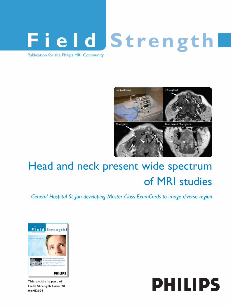
MRI helps evaluate extent of tumorinvasion in larynxPatient presents with thickened left vocal cordcaused by a tumor.Top row: arrows indicatenormal laryngeal anatomy, and high signalintensity tumor invading anterior of left paraglottic fat space of left true vocal cord.Bottom row: left image shows enhancing tumor(arrowheads) compressing anterior of right truevocal cord. In the image of the complete neckthe resolution is reduced, but true vocal cordtumor (white arrow), false cord (upper whitearrow) and infraglottic (arrowhead) extensionare still seen. CLEAR was applied in allsequences.
T2-weighted T1-weighted
Post-contrast T1-weighted Post-contrast T1-weighted
"All head and neck imaginginvolves two critical things:position coils close to the skinand use SENSE or CLEAR."
9Issue 28 - April 2006 Field Strength
“If I used the head and neck coil alone, itsdetectors are four centimeters from theskin, which causes tremendous signal loss.Even 3.0T probably would not recover thatlost signal,” he observes. “Since the Flex-Scoils are linked, you can also use bothSENSE and CLEAR. CLEAR is fantasticbecause it allows signal homogenizationfrom left to right without a drop-off at thecenter. With SENSE and CLEAR you canalso acquire 1024-matrix images – withexcellent SNR and image detail, foranatomy such as the orbits and ears – in just four minutes.”
In the inner ear, strong signal combinedwith a high-resolution matrix helps cliniciansdistinguish small nerves and the structures ofthe cochlea, such as the scala tympani andscala vestibuli. In the orbits, high SNR andmatrix are necessary to resolve the tinymuscles on the globe of the eyeball and theoptic nerve at its entrance to the globe.
Larynx imaging reveals organ’s variedanatomyImaging of laryngeal anatomy requiressome manipulation of Flex-S coils (withinthe SENSE Head/Neck coil) to optimizesignal, Dr. Casselman indicates. “Theyneed to form a collar around the neck,” hesays. “I even use tape to fix them closer tothe neck. The images are far superior tothose we’ve acquired in the past, when we
could hardly see the larynx due to lowsignal and low spatial resolution. We wouldlengthen sequences to five or six minutes tobuild signal and resolution, but eventuallypatients would swallow. Now, we have somuch signal that we can reduce scan timeto two minutes, or, alternatively, increasescan time to 3.5 minutes in cooperativepatients to provide even higher resolution.With these techniques, we can acquireexcellent images that show not only thevocal cords, but also the muscles andligaments that compose them, as well asossified and non-ossified cartilage – you cansee everything. At General Hospital St. Jan,our surgeons no longer want CT scans ofthe larynx.”
St. Jan’s surgeons rely on larynx MRIimages to inform interventional choices.For example, if laser therapy is an option,surgeons will want to know the extent oftumor invasion in the muscle to determineif they can still ablate it. Similarly, ifcartilage invasion is identified, then surgeryis no longer an option and is replaced bypossible total laryngectomy.
MRI with close-fitting, Flex-S coilspositioned bilaterally on the cheek producessuperb images to assist in staging tumors inthe oral cavity, Dr. Casselman adds. “You will see cortical bone invasion on CT, but not the extent of invasion; it can
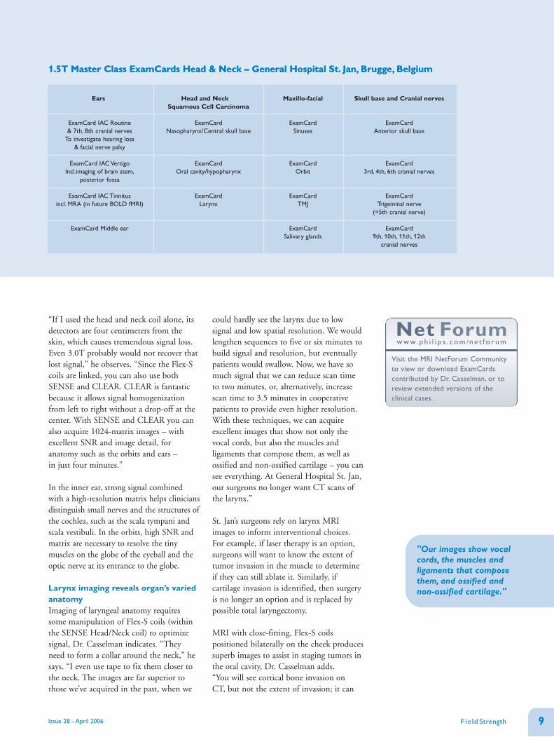
1.5T Master Class ExamCards Head & Neck – General Hospital St. Jan, Brugge, Belgium
Ears
ExamCard IAC Routine & 7th, 8th cranial nerves
To investigate hearing loss & facial nerve palsy
ExamCard IAC VertigoIncl.imaging of brain stem,
posterior fossa
ExamCard IAC Tinnitusincl. MRA (in future BOLD fMRI)
ExamCard Middle ear
Head and Neck Squamous Cell Carcinoma
ExamCard Nasopharynx/Central skull base
ExamCard Oral cavity/hypopharynx
ExamCardLarynx
Maxillo-facial
ExamCard Sinuses
ExamCardOrbit
ExamCardTMJ
ExamCard Salivary glands
Skull base and Cranial nerves
ExamCard Anterior skull base
ExamCard 3rd, 4th, 6th cranial nerves
ExamCard Trigeminal nerve
(=5th cranial nerve)
ExamCard 9th, 10th, 11th, 12th
cranial nerves
"Our images show vocalcords, the muscles andligaments that composethem, and ossified and non-ossified cartilage."
1.5T Master Class ExamCards Head & Neck – General Hospital St. Jan, Brugge, Belgium
Net Forumw w w. p h i l i p s . c o m /n e t f o r u m
Visit the MRI NetForum Communityto view or download ExamCardscontributed by Dr. Casselman, or toreview extended versions of theclinical cases.

10 Issue 28 - April 2006
be five centimeters in and you don’t seeanything on CT.”
With flexible surface coils positionedslightly more posteriorly, St. Jan radiologistsimage the salivary glands using a 1024matrix. The most common tumor of thesalivary glands is a pleomorphic adenoma(benign mixed tumor).
In imaging studies of either the larynx ororal cavity, Dr. Casselman emphasizes thatwhile tumor detection and staging are theprimary goals, the final sequence employsthe SENSE Head/Neck coil in a coronalsequence covering the entire neck from theskull base to the thoracic inlet and enablinglymph node staging.
Inner ear imaging requires tailoredapproachGeneral Hospital St. Jan has developedExamCards for IAC Routine, IAC Vertigoand IAC Tinnitus, which are available onPhilips’ NetForum for immediatedownload to eligible users. The IACRoutine ExamCard for investigation ofhearing loss uses the SENSE Head coil andimplements a T2-weighted sequence of thebrain to exclude tumor. Subsequently,bilateral Flex-S coils are used and a T2-weighted DRIVE sequence is applied toobtain ultra-high resolution images ofsmall inner ear anatomy, such as thenerves. Use of SENSE is necessary tomaintain a reasonable scan time whenusing a 1024 matrix.
The third and final sequence – a 3D, T1-weighted, contrast-enhanced PCA sequence– focuses again on the inner ear and on thecerebropontine angle to exclude enhancinglesions, labyrinthitis and meningealenhancement.
The IAC Vertigo ExamCard adds a highresolution scan to evaluate the brain stemand posterior fossa, where the pathologyresponsible for vertigo often is found.“Equilibrium changes can usually be tracedto nuclei in the brain stem or in theafferent or efferent vestibular pathways inthe posterior fossa,” Dr. Casselman notes.“The selective proton density T2-weightedsequence ensures we don’t miss anyinfarction, tumor or MS in that area.”
High resolution TOF MIP Post-contrast TOF
Gd-enhanced TOF image (different patient) throughleft jugular foramen, showing hypointense lesion(white arrowheads) in enhancing jugular bulb. Highsignal intensity fast flow (black arrowhead) is seeninside lesion, confirming diagnosis of glomus tumor.
High-resolution TOF image depicts fast flow in left sigmoid sinus (black arrow), indicatingpresence of arteriovenous dural fistula. Note normal low signal intensity in right sigmoidsinus (white arrow). In the MIP reconstructions, fast flow in sigmoid sinus (arrow) is seen,caused by fistulas originating from middle meningeal (white arrowheads) and occipitalarteries (grey arrowheads).
Gingival thickening suggestive of a tumor, or abscess due totooth extractionThe T2-weighted high-resolution image shows squamous cell carcinomainvading right cheek fat (white arrow) and mandible (arrowheads). Blackarrow indicates normal lingual nerve.The high resolution T1-weightedimage shows hypointense tumor (white arrow) invading intra-mandiblemarrow, destroying lingual and buccal cortex (arrowheads). Normal blacklingual cortex (black arrows). Post-contrast image shows enhancing tumor(white arrowheads) and disappearance of normal cortex and marrow ofright mandible.The marrow of remaining inferior part of right mandiblehas decreased signal (black arrowhead) due to tumor invasion.
Coil positioning T2-weighted
T1-weighted Post-contrast T1-weighted
TOF assists in diagnosis of two patients with left-sided tinnitus

11Field Strength
A recent addition to the IAC VertigoExamCard for older patients is a diffusionsequence to improve the likelihood ofdetecting an acute infarction in the posteriorfossa, one of the most frequent causes ofacute vertigo.
The IAC Tinnitus ExamCard coverspatients with suspected tinnitus, thesubjective or objective perception of sound.In addition to the routine T2-weighted brainsurvey, DRIVE and T1-weighted PCAsequences, IAC Tinnitus employs an MRAsequence with and without contrast toevaluate posterior fossa vessels.
“The MRA sequence can reveal vascularlesions, such as glomus tumors, which cancause tinnitus as well as other possiblevascular causes of tinnitus, includingmeningiomas around the temporal bone,dural fistulas and carotid dissections,” Dr.Casselman says.
The IAC Tinnitus ExamCard may also berefined in the near future with the additionof a BOLD fMRI sequence. “If you comparepeople with tinnitus with the normalpopulation, tinnitus sufferers have lessactivation – from the perceived sound – onthe contralateral cortex where in normals youexpect activation. In effect, the tinnitus hassaturated the contralateral side with sound,so activation migrates to adjacent same-sideareas, an effect we can see with BOLDfMRI,” he explains. “Therefore, it is easier toconfirm if the patient has tinnitus and to
identify on which side to direct treatments,such as extracorporeal magneticstimulation.”
Middle ear is site of most commonpathologyThe most frequent examined middle earpathology is cholesteatoma, whicheventually can completely destroy theossicles of the middle ear and cansubsequently affect the inner ear, resultingin complete deafness. With CT, it is oftenimpossible to confirm the presence of acholesteatoma in a completely obliteratedmiddle ear, but with specific MRIsequences and Flex-S coils, definitivediagnoses can now be made, Dr. Casselmanmaintains.
“The two most important sequences are alate-enhancement T1 sequence and a non-EPI diffusion sequence,” he says. “If noenhancement is noted after 45 minutes, thelesion is likely a cholesteatoma, unless thelesion under study is a cyst. To rule out acyst, the diffusion sequence is run and ifthere is high diffusion signal at a b-value of1000 then that indicates a cholesteatoma –because cysts have high ADC and thus lowsignal on the b-1000 images.”
In the past, the inability to discern betweencholesteatoma and other middle earpathology compelled exploratory surgeryfor all patients whose CT scan merelyshowed an obliterated middle ear with noconvincing evidence of a potentially
Coil positioning
Non-EPI DWI b=0
T2-weighted
Non-EPI DWI b=1000
Post-contrast T1-weighted
EPI DWI b=1000
Differentiating between inflammation andcholesteatomaPatient has CT-confirmed middle ear obliteration. SENSE Flex-Scoils (black arrows) within SENSE Head coil are used for middleand inner ear. T2-weighted image depicts inner ear fluid(arrowhead), and bright lesion in antrum and mesotympanum(arrow). The 45 min. post-contrast T1-weighted image shows fluidin inner ear (white arrowhead), non-enhancing lesion in antrumand mesotympanum (arrow) with peripheral rim enhancement(black arrowhead). T2 and post-contrast findings are typical forcholesteatoma. On both non-EPI DWI images a hyperintenselesion is seen in antrum and mesotympanum (arrowhead) – thetypical DWI appearance of cholesteatoma. On EPI DWI imagelesion is hyperintense (white arrow), but is deformed andsusceptibility artifacts obscure its location near the tegmen(arrowhead).
aggressive lesion. “Even more interesting,patients whose middle ear damage wasfrom a cholesteatoma need second-looksurgery 6-12 months post-operatively,” Dr. Casselman notes. “However, for allcholesteatoma patients, recurrence is lessthan 10%, so 90% of patients are operatedon for nothing. An MRI study specificallygeared to help doctors detect cholesteatomacould help reduce the major costs andinvasiveness involved in unnecessarysecond-look surgery.”
Microcoils improve “close-to-the-surface” head and neck studiesAt St. Jan, the preferred RF coils for headand neck studies are the flexible SENSEFlex-S coils, which provide excellent SNReven for centerline anatomy when placedclose to the skin. However, when highresolution is needed to visualize known,close-to-the-surface pathology or anatomy,such as nerves, TMJ joint or eyeball, Dr. Casselman uses Philips’ 47 mmMicroscopy coil.
“We don’t even need to use a 2048 matrix,because we can significantly reduce slicethickness and FOV,” he says. “So, if I‘smear out’ the 1024 matrix over a verysmall FOV, I can get very high resolution.For example, we acquired some beautifulimages of the globe of the eye in which wethink we can see the retina. Or, we canvisualize the branches of the facial nervethat enter the parotid gland. You can’t seethis anatomy with regular coils.”