Embed Size (px)
Citation preview

Part Number:
F IER Y X-3800CP INSTALLATION AND SER VICE GUIDE
A g u i d e f o r s e r v i c e t e c h n i c i a n s
Pr e l i m i n a r y D r a f t 3 / 5 / 9 9
T h i s I n s t a l l a t i o n a n d S e r v i c e G u i d e i s i n t e n d e d t o p r o v i d e a n u n d e r s t a n d i n g o f t h e F i e r y X - 3 8 0 0 C P a n d i t s i n t e r n a l c o m p o n e n t s . S o m e p r o c e d u r e s i n t h i s g u i d e a r e i n c l u d e d f o r i n f o r m a t i o n o n l y a n d w i l l n o t n e c e s s a r i l y b e p e r f o r m e d .


Copyright © 1999 Electronics for Imaging, Inc. All rights reserved.
This publication is protected by copyright, and all rights are reserved. No part of it may be reproduced or transmitted in any form or by any means for any purpose without express prior written consent from Electronics for Imaging, Inc., except as expressly permitted herein. Information in this document is subject to change without notice and does not represent a commitment on the part of Electronics for Imaging, Inc.
The software described in this publication is furnished under license and may only be used or copied in accordance with the terms of such license.
Patents: 5,666,436; 5,553,200; 5,543,940; 5,537,516; 5,517,334; 5,506,946;5,424,754; 5,343,311; 5,212,546; 4,941,038; 4,837,722; 4,500,919
Trademarks
EFI, the EFI logo, Fiery, the Fiery logo, and Rip-While-Print are trademarks registered in the U.S. Patent and Trademark Office. Fiery ZX, Fiery X-3800CP, Fiery Driven, the Fiery Driven logo, Command WorkStation, AutoCal, Starr Compression, Memory Multiplier, ColorWise, NetWise, and VisualCal are trademarks of Electronics for Imaging, Inc.
Adobe, the Adobe logo, Adobe Illustrator, PostScript, Adobe Photoshop, Adobe Separator, and Adobe PageMaker are registered trademarks of Adobe Systems Incorporated, registered in certain jurisdictions. EPS (Encapsulated PostScript) is a trademark of Altsys Corporation. Apple, the Apple logo, AppleShare, AppleTalk, EtherTalk, LaserWriter, and Macintosh are registered trademarks, and MultiFinder is a trademark of Apple Computer, Inc. Microsoft, MS, MS-DOS, and Windows are registered trademarks of Microsoft in the US and other countries. QuarkXPress is a registered trademark of Quark, Inc. Times, Helvetica, and Palatino are trademarks of Linotype AG and/or its subsidiaries. ITC Avant Garde, ITC Bookman, ITC Zapf Chancery, and ITC Zapf Dingbats are registered trademarks of International Typeface Corporation. Ethernet is a registered trademark of Xerox Corporation. Farallon, PhoneNET PC, and PhoneNET Talk are trademarks of Farallon Computing, Inc. NetWare and Novell are registered trademarks and Internetwork Packet Exchange (IPX) is a trademark of Novell, Inc. SyQuest is a registered trademark, in the United States and certain other countries, of SyQuest Technology, Inc. UNIX is a registered trademark of UNIX System Laboratories, a wholly owned subsidiary of Novell, Inc. PANTONE is a registered trademark of Pantone, Inc.
All other terms and product names may be trademarks or registered trademarks of their respective owners, and are hereby acknowledged.
Legal Notices
APPLE COMPUTER, INC. (“APPLE”) MAKES NO WARRANTIES, EXPRESS OR IMPLIED, INCLUDING WITHOUT LIMITATION THE IMPLIED WARRANTIES OF MERCHANTABILITY AND FITNESS FOR A PARTICULAR PURPOSE, REGARDING THE APPLE SOFTWARE. APPLE DOES NOT WARRANT, GUARANTEE, OR MAKE ANY REPRESENTATIONS REGARDING THE USE OR THE RESULTS OF THE USE OF THE APPLE SOFTWARE IN TERMS OF ITS CORRECTNESS, ACCURACY, RELIABILITY, CURRENTNESS, OR OTHERWISE. THE ENTIRE RISK AS TO THE RESULTS AND PERFORMANCE OF THE APPLE SOFTWARE IS ASSUMED BY YOU. THE EXCLUSION OF IMPLIED WARRANTIES IS NOT PERMITTED BY SOME STATES. THE ABOVE EXCLUSION MAY NOT APPLY TO YOU.
IN NO EVENT WILL APPLE, ITS DIRECTORS, OFFICERS, EMPLOYEES OR AGENTS BE LIABLE TO YOU FOR ANY CONSEQUENTIAL, INCIDENTAL OR INDIRECT DAMAGES (INCLUDING DAMAGES FOR LOSS OF BUSINESS PROFITS, BUSINESS INTERRUPTION, LOSS OF BUSINESS INFORMATION, AND THE LIKE) ARISING OUT OF THE USE OR INABILITY TO USE THE APPLE SOFTWARE EVEN IF APPLE HAS BEEN ADVISED OF THE POSSIBILITY OF SUCH DAMAGES. BECAUSE SOME STATES DO NOT ALLOW THE EXCLUSION OR LIMITATION OF LIABILITY FOR CONSEQUENTIAL OR INCIDENTAL DAMAGES, THE ABOVE LIMITATIONS MAY NOT APPLY TO YOU. Apple’s liability to you for actual damages from any cause whatsoever, and regardless of the form of the action (whether in contract, tort [including negligence], product liability or otherwise), will be limited to $50.
Restricted Rights Legends
For defense agencies: Restricted Rights Legend. Use, reproduction, or disclosure is subject to restrictions set forth in subparagraph (c)(1)(ii) of the Rights in Technical Data and Computer Software clause at 252.227.7013.
For civilian agencies: Restricted Rights Legend. Use, reproduction, or disclosure is subject to restrictions set forth in subparagraph (a) through (d) of the commercial Computer Software Restricted Rights clause at 52.227-19 and the limitations set forth in Electronics for Imaging, Inc.’s standard commercial agreement for this software. Unpublished rights reserved under the copyright laws of the United States.
Printed in the United States of America on recycled paper.
FCC Information
WARNING: FCC Regulations state that any unauthorized changes or modifications to this equipment not expressly approved by the manufacturer could void the user’s authority to operate this equipment.
Responsible Party (in USA)—Electronics for Imaging, Inc.Address—2855 Campus Drive, San Mateo, CA 94403Telephone—650-524-4300
Industry Canada Class B Notice
This Class B digital apparatus meets all the requirements of the Canadian Interference-Causing Equipment Regulations.
Avis de Conformation Classe B de l’Industrie Canada
Cet appareil numérique de la classe B respecte toutes les exigences du Règlement sur le matériel brouilleur du Canada.
RFI Compliance Notice
This equipment has been tested concerning compliance with the relevant RFI protection requirements both individually and on system level (to simulate normal operation conditions). However, it is possible that these RFI Requirements are not met under certain unfavorable conditions in other installations. It is the user who is responsible for compliance of his particular installation.
Dieses Geraet wurde einzeln sowohl als auch in einer Anlage, die einen normalen Anwendungsfall nachbildet, auf die Einhaltung der Funk-entstoerbestimmungen geprueft. Es ist jedoch moeglich, dass die Funk-enstoerbestimmungen unter unguenstigen Umstaenden bei anderen Geraetekombinationen nicht eingehalten werden. Fuer die Einhaltung der Funk-entstoerbestimmungen seigner gesamten Anlage, in der dieses Geraet betrieben wird, ist der Betreiber verantwortlich.
Compliance with applicable regulations depends on the use of shielded cables. It is the user who is responsible for procuring the appropriate cables.
Einhaltung mit betreffenden Bestimmungen kommt darauf an, dass geschirmte Ausfuhrungen gebraucht werden. Fuer die beschaffung richtiger Ausfuhrungen ist der Betreiber verantwortlich.
Proprietary Rights
You acknowledge that the Software, Coded Font Programs, Typefaces, Trademarks and accompanying documentation are proprietary to Electronics for Imaging and its suppliers and that title and other intellectual property rights therein remain with Electronics for Imaging and its suppliers. Except as stated above, this Agreement does not grant you any right to patents, copyrights, trade secrets, trademarks (whether registered or unregistered), or any other rights, franchises or licenses in respect of the Software, Coded Font Programs, Typefaces, Trademarks or accompanying documentation. You may not adapt or use any trademark or trade name which is likely to be similar to or confusing with that of Electronics for Imaging or any of its suppliers or take any other action which impairs or reduces the trademark rights of Electronics for Imaging or its suppliers. The trademarks may only be used to identify printed output produced by the Coded Font Programs. At the reasonable request of Electronics for Imaging, you must supply samples of any Typeface identified with a trademark.
The MacApp software is proprietary to Apple Computer, Inc. and is licensed to Electronics for Imaging, Inc. for distribution only for use in combination with Fiery software utilities.
Confidentiality
You agree to hold the Software and Coded Font Programs in confidence, disclosing the Software and Coded Font Programs only to authorized users having a need to use the Software and Coded Font Programs as permitted by this Agreement and to take all reasonable precautions to prevent disclosure to other parties.
Remedies
Unauthorized use, copying or disclosure of the Software, Coded Font Programs, Typefaces, Trademarks or accompanying documentation will result in automatic termination of this license and will make available to Electronics for Imaging other legal remedies.
Limited Warranty And Disclaimer
Electronics for Imaging warrants that, for a period of ninety (90) days from the date of delivery to you, the Software under normal use will perform without significant errors that make it unusable. Electronics for Imaging’s entire liability and your exclusive remedy under this warranty (which is subject to you returning Fiery X-3800CP to Electronics for Imaging or an authorized dealer) will be, at Electronics for Imaging’s option, to use reasonable commercial efforts to attempt to correct or work around errors, to replace the Software with functionally equivalent software, or to refund the purchase price and terminate this Agreement. Some states do not allow limitations on duration of implied warranty, so the above limitation may not apply to you.
Except for the above express limited warranty, Electronics for Imaging makes and you receive no warranties or conditions on the Products, express, implied, or statutory, and Electronics for Imaging specifically disclaims any implied warranty or condition of merchantability or fitness for a particular purpose.
For warranty service, please contact your authorized service/support center.
EXCEPT FOR THE ABOVE EXPRESS LIMITED WARRANTY, ELECTRONICS FOR IMAGING MAKES AND YOU RECEIVE NO WARRANTIES OR CONDITIONS ON THE SOFTWARE OR CODED FONT PROGRAMS, EXPRESS, IMPLIED, STATUTORY, OR IN ANY OTHER PROVISION OF THIS AGREEMENT OR COMMUNICATION WITH YOU, AND ELECTRONICS FOR IMAGING SPECIFICALLY DISCLAIMS ANY IMPLIED WARRANTY OR CONDITION OF MERCHANTABILITY OR FITNESS FOR A PARTICULAR PURPOSE. Electronics for Imaging does not warrant that the operation of the software will be uninterrupted or error free or that the Software will meet your specific requirements.
Limitation Of Liability
IN NO EVENT WILL ELECTRONICS FOR IMAGING OR ITS SUPPLIERS BE LIABLE FOR ANY DAMAGES, INCLUDING LOSS OF DATA, LOST PROFITS, COST OF COVER OR OTHER SPECIAL, INCIDENTAL, CONSEQUENTIAL OR INDIRECT DAMAGES ARISING FROM THE USE OF THE SOFTWARE, CODED FONT PROGRAMS OR ACCOMPANYING DOCUMENTATION, HOWEVER CAUSED AND ON ANY THEORY OF LIABILITY. THIS LIMITATION WILL APPLY EVEN IF ELECTRONICS FOR IMAGING OR ANY AUTHORIZED DEALER HAS BEEN ADVISED OF THE POSSIBILITY OF SUCH DAMAGE. YOU ACKNOWLEDGE THAT THE PRICE OF THE UNIT REFLECTS THIS ALLOCATION OF RISK. BECAUSE SOME STATES/JURISDICTIONS DO NOT ALLOW THE EXCLUSION OR LIMITATION OF LIABILITY FOR CONSEQUENTIAL OR INCIDENTAL DAMAGES, THE ABOVE LIMITATION MAY NOT APPLY TO YOU.

Export Controls
You agree that you will not export or re-export the Software or Coded Font Programs in any form without the appropriate United States and foreign government licenses. Your failure to comply with this provision is a material breach of this Agreement.
Government Use
Use, duplication or disclosure of the Software by the United States Government is subject to restrictions as set forth in subdivision (c) (1) (ii) of the Rights in Technical Data and Computer Software clause at DFARS 252.227-7013 or in subparagraphs (c) (1) and (2) of the Commercial Computer Software—Restricted Right Clause at 48 CFR 52.227-19, as applicable.
Third Party Beneficiary
You are hereby notified that Adobe Systems Incorporated, a California corporation located at 345 Park Avenue, San Jose, CA 95110 USA (“Adobe”) is a third-party beneficiary to this Agreement to the extent that this Agreement contains provisions which relate to your use of the Fonts, the Coded Font Programs, the Typefaces and the Trademarks licensed hereby. Such provisions are made expressly for the benefit of Adobe and are enforceable by Adobe in addition to Electronics for Imaging.
General
This Agreement will be governed by the laws of the State of California.
This Agreement is the entire agreement held between us and supersedes any other communications or advertising with respect to the Software, Coded Font Programs and accompanying documentation.
If any provision of this Agreement is held invalid, the remainder of this Agreement shall continue in full force and effect.
If you have any questions concerning this Agreement, please write to Electronics for Imaging, Inc., Attn: Licensing Dept. or see Electronics for Imaging’s web site at www.efi.com.
Electronics for Imaging, Inc.303 Velocity WayFoster City, CA 94404

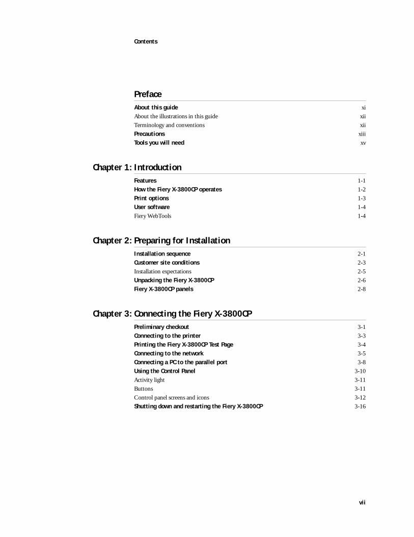
Contents
PrefaceAbout this guide xi
About the illustrations in this guide xii
Terminology and conventions xii
Precautions xiii
Tools you will need xv
Chapter 1: IntroductionFeatures 1-1
How the Fiery X-3800CP operates 1-2
Print options 1-3
User software 1-4
Fiery WebTools 1-4
Chapter 2: Preparing for InstallationInstallation sequence 2-1
Customer site conditions 2-3
Installation expectations 2-5
Unpacking the Fiery X-3800CP 2-6
Fiery X-3800CP panels 2-8
Chapter 3: Connecting the Fiery X-3800CPPreliminary checkout 3-1
Connecting to the printer 3-3
Printing the Fiery X-3800CP Test Page 3-4
Connecting to the network 3-5
Connecting a PC to the parallel port 3-8
Using the Control Panel 3-10
Activity light 3-11
Buttons 3-11
Control panel screens and icons 3-12
Shutting down and restarting the Fiery X-3800CP 3-16
vii
Contents
Chapter 4: Service ProceduresOverview 4-1
System software service 4-1
Accessing internal components 4-3
Accessing front panel components 4-7
Checking internal connections 4-9
Restoring functionality after service 4-12
Removing and replacing circuit boards 4-14
User interface board 4-14
Motherboard 4-17
Fans 4-24
Exhaust fan 4-24
CPU fan 4-25
Power switch 4-27
Power supply 4-30
Hard disk drive 4-35
Front panel components 4-38
Jewels 4-39
Buttons 4-39
Fiery X-3800CP system software 4-40
System software installation reminders 4-41
Installing system software using the SCSI interface port 4-42
Installing system software using the parallel port 4-46
Chapter 5: Troubleshooting ProceduresThe troubleshooting process 5-1
Where problems occur 5-3
Before you go to the customer site 5-4
Preliminary on-site checkout 5-6
Checking interface cables 5-6
Checking internal components 5-7
Checking the Fiery X-3800CP as a stand-alone unit 5-9
Errors during Start-up diagnostics 5-9
General Fiery X-3800CP system error conditions 5-11
System software installation error messages 5-14
Fiery X-3800CP diagnostic sets 5-17
Viewing the diagnostic report 5-22
Checking the entire Fiery X-3800CP system 5-23
Checking the printer interface 5-23
Checking network connections 5-25
Printing to the Fiery X-3800CP 5-26
viii
Contents
Appendix A: SpecificationsHardware features A-1
Networking and connectivity A-1
User software A-1
Safety and emissions compliance A-1
Index
ix

About this guide
This Installation and Service Guide is intended to provide an understanding of the Fiery X-3800CP and its internal components to Technical Support personnel. Some procedures included in the guide will not be used. Fiery X-3800CP customers should not use this technical service documentation.
About this guideThis guide is divided into the following sections:
• “Preface”
General information about this guide Fiery X-3800CP.
• Chapter 1, “Introduction”
General information about the Fiery X-3800CP.
• Chapter 2, “Preparing for Installation”
Unpacking and the steps customers need to take to install the unit.
The Customer is responsible for installing the Fiery X-3800CP at the site. The procedures in this chapter are provided for your information only. Some information provided in this chapter is also included in Getting Started.
• Chapter 3, “Connecting the Fiery X-3800CP”
How to connect the Fiery X-3800CP to the printer and the network and verify that the system is working correctly; overview of Control Panel.
The customer is responsible for connecting the Fiery X-3800CP to the printer and the network at the site. The information in this chapter is provided for your information only. The connecting section of this chapter is also included in Getting Started.
• Chapter 4, “Service Procedures”
Removal and replacement procedures for Fiery X-3800CP components.
Some procedures in this chapter are included for information only and are not required for Fiery X-3800CP systems.
• Chapter 5, “Troubleshooting Procedures”
Common problems and ways of correcting them; startup errors.
The information in this chapter will aid you in diagnosing problems that customers may experience. Some actions may suggest that you perform procedures not supported on the Fiery X-3800CP.
Preface
xi
Preface
About the illustrations in this guideThe illustrations in this guide reflect the current shipping version of the Fiery X-3800CP at the time of publication. Components shown in these illustrations are subject to change.
Terminology and conventionsThe term “network administrator” refers to the person responsible for maintaining the network at the customer site.
The term “Control Panel” refers to the area on the front of the Fiery X-3800CP including the green/red activity light, the display window (LCD—liquid crystal display), and the black oval plastic disk surrounding the display window.
The term “system software” refers to the software installed on the Fiery X-3800CP hard disk drive.
The term “PC” refers to any IBM PC or compatible computer running Windows.
The term “100BaseT” is used throughout this manual to refer to 100BaseTX.
The term “parallel port” refers to the Parallel In port for connection to a PC. The term “printer interface port” refers to the Parallel Out port for connection to the printer.
References to other Fiery X-3800CP manuals, such as the Administrator Guide, are displayed in italics.
The note indicator highlights important messages and additional information.
The caution icon indicates a need for special care and safety when handling the equipment.
NOTE:
xii
Precautions
PrecautionsAlways observe the following general precautions when installing and servicing the Fiery X-3800CP:
1. Report any shipping damage.
If there is any evidence of shipping or handling damage to the Fiery X-3800CP packing boxes or their contents, save the damaged boxes and parts, call the shipper immediately to file a claim and notify your authorized service/support center.
2. Never alter an existing network without permission.
The Fiery X-3800CP will probably be connected to an existing Local Area Network (LAN) based on Ethernet hardware. The network is the link between the customer’s computer, existing printer, and other equipment. Never disturb the LAN by breaking or making a network connection, altering termination, installing or removing networking hardware or software, or shutting down networked devices without the knowledge and express permission of the network administrator or the shop supervisor.
3. Never enter an IP address in Fiery X-3800CP Network Setup.
Only the network administrator should enter an IP address on a network device. Assigning a Fiery X-3800CP an incorrect IP address can cause unpredictable errors on any or all devices connected to the network.
4. Always disconnect power before opening the Fiery X-3800CP chassis.
Although Fiery X-3800CP circuitry operates on 3.3V DC, 5V DC, and ±12V DC, 100-240V AC is present when the chassis cover is removed. Inside the chassis, the power supply is not encased. Before you service the Fiery X-3800CP, shut it down completely and unplug the AC power cable from the back.
5. Handle the Fiery X-3800CP glass display window with care.
If the glass on the user interface board breaks and the liquid crystal inside leaks out, avoid contact with it. If you do come in contact with the liquid crystal, wash it off with soap and water immediately.
Avoid pressing the surface of the glass display window. Applying pressure to the glass display window on the user interface board will cause it to change color.
Use a soft cloth moistened with isopropyl or ethyl alcohol to clean the glass display window. Other solvents, such as water, may damage the polarizer.
xiii
Preface
6. Follow standard ESD (electrostatic discharge) precautions while working on the internal components of the Fiery X-3800CP.
Static is always a concern when servicing electronic devices. It is highly unlikely that the area around the printer and the Fiery X-3800CP is static-free. Carpeting, leather-soled shoes, synthetic clothing fibers, silks, and plastics may generate a static charge of more than 10,000 volts. Static discharge is capable of destroying the circuits etched in silicon microchips, or dramatically shortening their life span. By observing standard precautions, you may avoid extra service calls and save the cost of a new board.
When possible, work on a ground-connected antistatic mat. Wear an antistatic wristband, grounded at the same place as the antistatic mat. If that is not possible:
• Attach a grounding strap to your wrist. Attach the other end to a good ground.
• When you unpack the Fiery X-3800CP from the carton for the first time, touch a metal area to discharge the static on your body.
• Before you handle internal components, touch a metal part of the Fiery X-3800CP.
• Leave new electronic components inside their antistatic bags until you are ready to install them. When you remove components from an antistatic bag, place them on a grounded antistatic surface, component-side up.
• When you remove an electronic component, place it into an antistatic bag immediately. Do not walk across a carpet or vinyl floor while carrying an unprotected board.
7. Handle printed circuit boards by their edges only, but avoid touching the contacts on the edge of the board.
8. Never set a cup of coffee—or any liquid—on or near the Fiery X-3800CP or the printer.
xiv

Tools you will need
Tools you will needThe following tools are required in order to perform the procedures described in Chapter 4, Service Procedures:
• ESD wrist grounding strap
• Antistatic mat
• Wire cutters
• #1 and #2 Phillips head screwdrivers (non-magnetic)
• Small flat-blade screwdriver (non-magnetic)
• Small needlenose pliers
• M3 metric wrench
• Flashlight
Also recommended:
• Ribbon cable connector extractor
xv

1
Features
The Fiery X-3800CP Color Server adds computer connectivity and highly efficient Adobe PostScript 3 color printing capacity to color printers. It is optimized for high-speed network communications, processing, rasterization, and printing of halftone and grayscale pages.
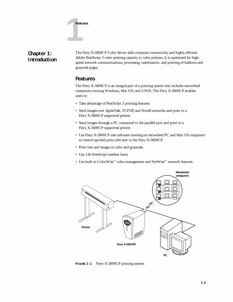
FeaturesThe Fiery X-3800CP is an integral part of a printing system that includes networked computers running Windows, Mac OS, and UNIX. The Fiery X-3800CP enables users to:
• Take advantage of PostScript 3 printing features.
• Send images over AppleTalk, TCP/IP, and Novell networks and print to a Fiery X-3800CP supported printer.
• Send images through a PC connected to the parallel port and print to a Fiery X-3800CP supported printer.
• Use Fiery X-3800CP user software running on networked PC and Mac OS computers to control spooled print jobs sent to the Fiery X-3800CP.
• Print text and images in color and grayscale.
• Use 136 PostScript resident fonts.
• Use built-in ColorWise™ color management and NetWise™ network features.
FIGURE 1-1 Fiery X-3800CP printing system
Chapter 1: Introduction
Networkedcomputers
Fiery X-3800CP
PC
Printer
1-1

1
Introduction
How the Fiery X-3800CP operatesThe Fiery X-3800CP enables the customer to access the printer through the network and use it to print files using advanced spooling and job control functions. Users can print to the Fiery X-3800CP from networked PCs, Mac OS computers, and UNIX workstations running TCP/IP. In addition, the Fiery X-3800CP parallel port can be used to print directly from a connected PC.
The Fiery X-3800CP custom-designed boards and system software are responsible for efficient image processing and printing controls. The main functions of Fiery X-3800CP components and software are described below.
The Fiery X-3800CP uses a specialized motherboard to process image data for printing images. The R5000 motherboard includes a MIPS R5000 RISC (Reduced Instruction Set Computer) CPU with a built-in floating point accelerator that runs the PostScript Interpreter, which interprets the page description file. The RipChip™ on the motherboard controls data management and other system functions, freeing up the CPU for efficient image data processing.
High-speed DIMMs (dual in-line memory modules) on the motherboard hold the image data during printing. The Fiery X-3800CP is originally configured for a minimum of 64MB of memory.
1-2
1
Print options
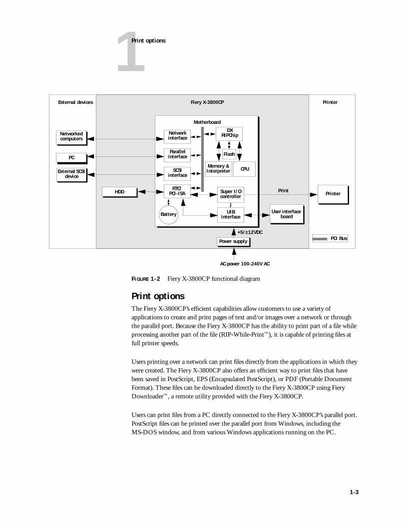
FIGURE 1-2 Fiery X-3800CP functional diagram
Print optionsThe Fiery X-3800CP’s efficient capabilities allow customers to use a variety of applications to create and print pages of text and/or images over a network or through the parallel port. Because the Fiery X-3800CP has the ability to print part of a file while processing another part of the file (RIP-While-Print™), it is capable of printing files at full printer speeds.
Users printing over a network can print files directly from the applications in which they were created. The Fiery X-3800CP also offers an efficient way to print files that have been saved in PostScript, EPS (Encapsulated PostScript), or PDF (Portable Document Format). These files can be downloaded directly to the Fiery X-3800CP using Fiery Downloader™, a remote utility provided with the Fiery X-3800CP.
Users can print files from a PC directly connected to the Fiery X-3800CP’s parallel port. PostScript files can be printed over the parallel port from Windows, including the MS-DOS window, and from various Windows applications running on the PC.
Motherboard
Power supply
External devices PrinterFiery X-3800CP
+5/±12VDC
AC power 100-240V AC
CPU
Network interface
User interface board
Memory &Interpreter
Printer
External SCSI device
DX RIPChip
Flash
Networked computers
PC
RTC/PCI-ISA
Parallel interface
SCSIinterface
Battery
HDD Super I/Ocontroller
UIBinterface
PCI Bus
1-3
1
Introduction
User softwareFiery X-3800CP user software is provided on the User Software CD. Some of the software can also be installed from the Fiery WebTools Installer (see Getting Started for more information on WebTools). The network administrator or the user at the customer site is responsible for installing software onto computers that will use the Fiery X-3800CP over a network.
The following software is included on the User Software CD:
Fiery WebToolsThe Fiery X-3800CP can support Internet or intranet access with Fiery WebTools. WebTools include Status, WebSpooler, Installer, and WebLink. For more information about WebTools, see the Administrator Guide and the User Guide.
Adobe PS Printer Driver Enables the user to print to the Fiery X-3800CP from Windows and Mac OS computers; also supports all
PostScript Printer Description (PPD) file
The Fiery X-3800CP PPD file provides information about the Fiery X-3800CP and the user’s printer to the application and printer driver. The PPD file is automatically installed when the printer driver is installed.
PS Screen Fonts(Mac OS only)
Installs screen fonts for the PostScript printer fonts installed on the Fiery X-3800CP. For a list of fonts, see the User Guide.
Fiery Downloader™ Enables the user to print PostScript, EPS, and PDF files directly to the Fiery X-3800CP without using the application in which they were created. Fiery Downloader also enables the user to manage the printer fonts installed on theFiery X-3800CP.
Fiery Print Calibrator™ Allows users to customize and maintain press simulations.
Fiery Spooler™ Enables the user to view the order and priority of print jobs, customize printer settings for jobs, delete jobs, and move jobs between queues. It can also be used to view job accounting information.
Color management files Profiles for color management systems.
Color reference files Color reference pages that help users take advantage of the range of colors on the Fiery X-3800CP.
1-4
2
Installation sequence
This chapter includes the following information:
• Summary of the installation sequence
• Checking the customer site
• Unpacking the Fiery X-3800CP
• Fiery X-3800CP front and back overview
NOTE: The customer is responsible for installing the Fiery X-3800CP at the site. The procedures in the chapter are provided for your information only. Some of the information provided in this chapter is also included in Getting Started.
Installation sequence
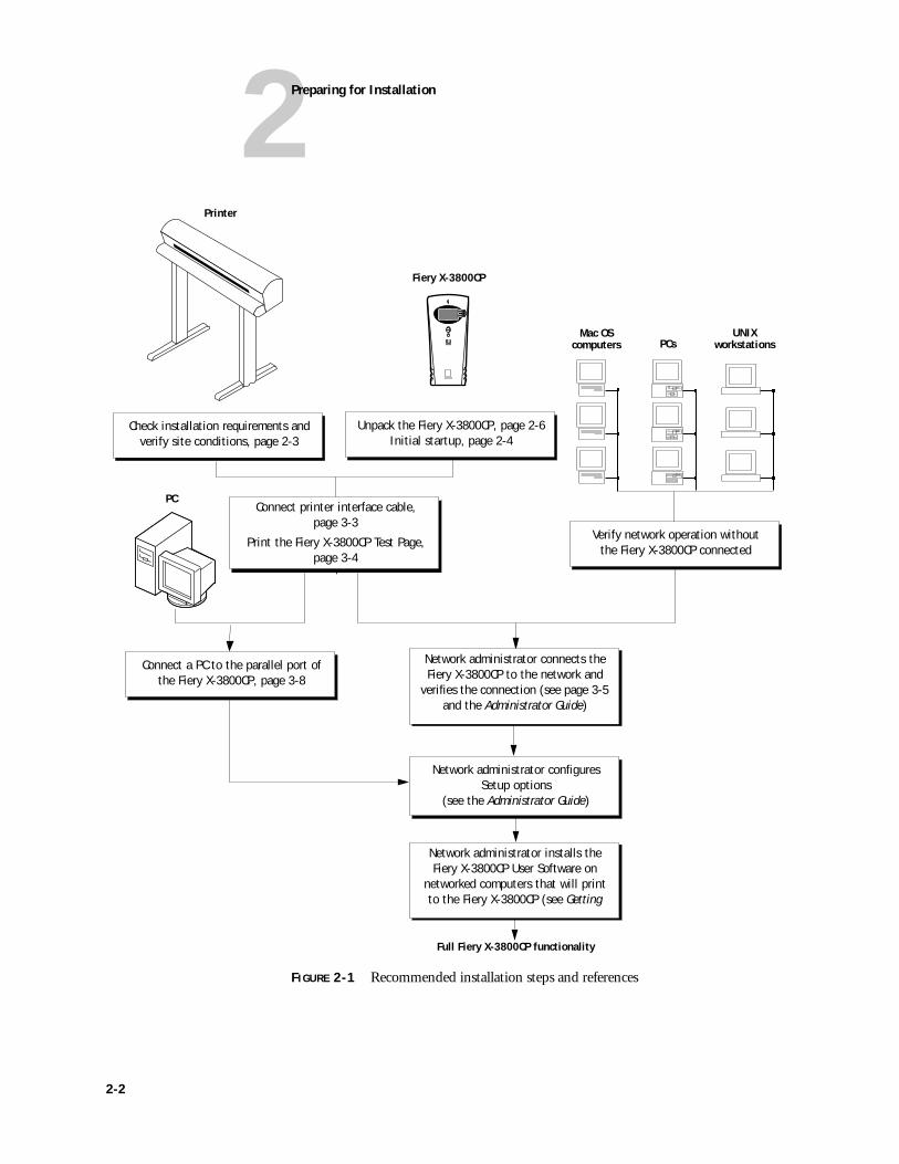
Familiarize yourself with Chapters 2 and 3 of this guide before you attempt an installation. The installation sequence described in this chapter is designed to make your job as easy as possible. Installation problems are easier to avoid and diagnose if you proceed from the component to the system level and verify functionality at each stage. Figure 2-1 on page 2-2 outlines the recommended installation procedure for connecting the Fiery X-3800CP to the printer.
Because the Fiery X-3800CP is a node on the customer’s computer network, make sure that you coordinate your scheduled installation with the network administrator at the customer site. Refer the network administrator to the Administrator Guide for network Setup information.
Chapter 2: Preparing for Installation
2-1
2
Preparing for Installation
FIGURE 2-1 Recommended installation steps and references
Mac OScomputers
UNIXworkstations
Printer
Fiery X-3800CP
Full Fiery X-3800CP functionality
PC
PCs
Unpack the Fiery X-3800CP, page 2-6Initial startup, page 2-4
Verify network operation without the Fiery X-3800CP connected
Connect a PC to the parallel port of the Fiery X-3800CP, page 3-8
Network administrator configures Setup options
(see the Administrator Guide)
Network administrator installs the Fiery X-3800CP User Software on
networked computers that will print to the Fiery X-3800CP (see Getting
Check installation requirements and verify site conditions, page 2-3
Connect printer interface cable, page 3-3
Print the Fiery X-3800CP Test Page, page 3-4
Network administrator connects the Fiery X-3800CP to the network and
verifies the connection (see page 3-5 and the Administrator Guide)
2-2
2Customer site conditions
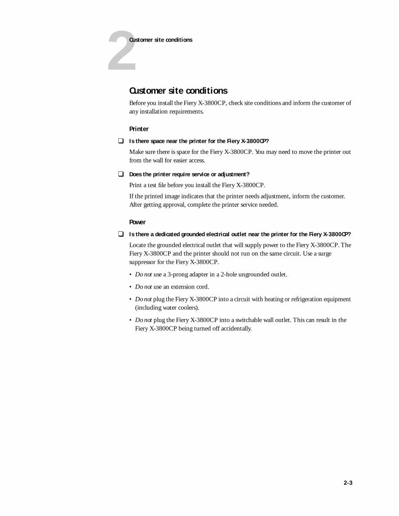
Customer site conditionsBefore you install the Fiery X-3800CP, check site conditions and inform the customer of any installation requirements.
Printer
❑ Is there space near the printer for the Fiery X-3800CP?
Make sure there is space for the Fiery X-3800CP. You may need to move the printer out from the wall for easier access.
❑ Does the printer require service or adjustment?
Print a test file before you install the Fiery X-3800CP.
If the printed image indicates that the printer needs adjustment, inform the customer. After getting approval, complete the printer service needed.
Power
❑ Is there a dedicated grounded electrical outlet near the printer for the Fiery X-3800CP?
Locate the grounded electrical outlet that will supply power to the Fiery X-3800CP. The Fiery X-3800CP and the printer should not run on the same circuit. Use a surge suppressor for the Fiery X-3800CP.
• Do not use a 3-prong adapter in a 2-hole ungrounded outlet.
• Do not use an extension cord.
• Do not plug the Fiery X-3800CP into a circuit with heating or refrigeration equipment (including water coolers).
• Do not plug the Fiery X-3800CP into a switchable wall outlet. This can result in the Fiery X-3800CP being turned off accidentally.
2-3
2Preparing for Installation
Network
❑ What is the network cable and connection type?
• Thinnet (10Base2)
• Thicknet (10Base5)
• Unshielded twisted pair (10/100BaseT)
❑ Is the network connection ready and tested for Fiery X-3800CP installation?
To verify that the network is functioning before you attach the Fiery X-3800CP:
• Ask the network administrator to print a document on a shared printer over the network.
• Ask the network administrator to verify the computer and network requirements as specified in the Getting Started.
Parallel (In) port
❑ Is there space for both the Fiery X-3800CP and the PC that will be connected to the Fiery X-3800CP?
❑ If system software installation is required and will be done over the parallel port:
• Can the parallel port on the PC be configured for ECP mode?
• Is the PC running Windows 95 or 98?
External SCSI device
❑ If system software installation is required and will be done using the SCSI interface port:
• Is an external CD-ROM drive available?
• Is a tested SCSI II to SCSI I cable available?
2-4
2Customer site conditions
Installation expectationsIf the site is ready, installation takes about one hour. The customer should be aware of the following:
• Some nodes on the network may be unavailable for up to one hour.
• The printer may be unavailable for up to one hour.
• The network administrator needs to be available during the installation for network connectivity.
Equipment downtime and impact on the network can be minimized if the network administrator installs a network connector for the Fiery X-3800CP and confirms network functionality with the connector in place before the date scheduled for the Fiery X-3800CP installation.
• The network administrator should have a networked computer available during the installation. The appropriate software should already be installed. Documentation for the networked computer and the network operating software should be available.
• The network administrator should install the user software shipped with the Fiery X-3800CP onto networked PC and Mac OS computers that will print to the Fiery X-3800CP. User documentation is provided with the Fiery X-3800CP.
NOTE: This guide covers Fiery X-3800CP installation and service. It provides general information on connecting the Fiery X-3800CP to the customer’s network. Network Setup and configuration information goes beyond the scope of this guide. For network Setup and configuration information, the network administrator should refer to the Administrator Guide.
2-5
2Preparing for Installation
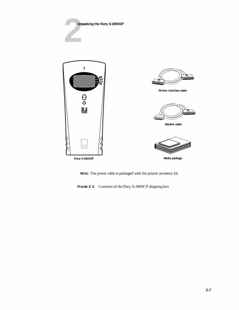
Unpacking the Fiery X-3800CPThe Fiery X-3800CP is assembled and shipped from the factory in a box that includes all necessary cables and documentation, as shown in Figure on page 2-6.
TO UNPACK THE FIERY X-3800CP
1. Open the box and remove any packing materials.
Save the original boxes and packing materials. If you need to transport the Fiery X-3800CP at a later date, the original box and packing material will ensure safe shipment.
2. Remove the contents from the top container. Inspect the contents for visible damage. The contents should include the following items:
• Bags containing the printer interface cable and parallel cable.
• Fiery X-3800CP media package (includes a package of user documentation, the User Software CD, and the System Software CD).
In order to take full advantage of the Fiery X-3800CP, user software must be installed on all computers that will print to it.
3. Set aside the remaining components from the top container.
4. Remove the top container and any packing materials. Set aside the packing material in case you need to reship the unit.
5. Carefully lift the Fiery X-3800CP out of the box.
If you notice shipping damage to any Fiery X-3800CP component, be sure to save the shipping container in case the carrier needs to see it. Call the carrier immediately to report the damage and file a claim, then call your authorized service/support center. Be ready to furnish the serial number, printed on the bottom of the chassis.
2-6
2Unpacking the Fiery X-3800CP
FIGURE 2-2 Contents of the Fiery X-3800CP shipping box
Fiery X-3800CP
Printer interface cable
Media package
Parallel cable
NOTE: The power cable is packaged with the printer accessory kit.
2-7
2Preparing for Installation
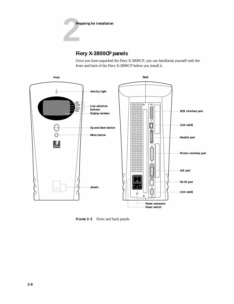
Fiery X-3800CP panelsOnce you have unpacked the Fiery X-3800CP, you can familiarize yourself with the front and back of the Fiery X-3800CP before you install it.
FIGURE 2-3 Front and back panels
Line selection buttons
Up and down button
Menu button
Display window
Activity light
Jewels
RJ-45 port
Parallel port
(not used)
Printer interface port
SCSI interface port
(not used)
AUI port
Power connectorPower switch
Front Back
2-8
3Preliminary checkout
This chapter contains the following information:
• Connecting power and checking out the Fiery X-3800CP
• Connecting the Fiery X-3800CP to the printer
• Printing the Test Page
• Connecting to the network
• Connecting a PC to the parallel port
• Shutting down and restarting the Fiery X-3800CP
This chapter also includes information on Control Panel screens and icons.
NOTE: The customer is responsible for connecting the Fiery X-3800CP to the printer and the network at the site. The information in this chapter is provided for your information only. The connecting section of this chapter is also included in Getting Started.
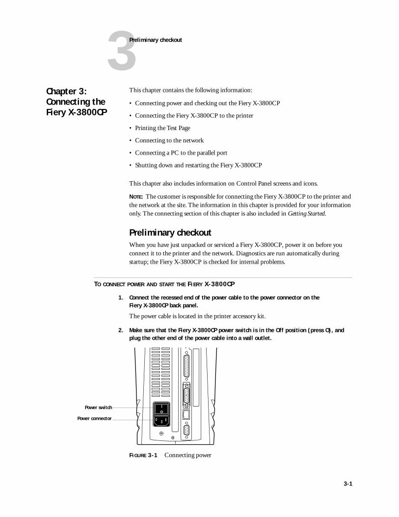
Preliminary checkoutWhen you have just unpacked or serviced a Fiery X-3800CP, power it on before you connect it to the printer and the network. Diagnostics are run automatically during startup; the Fiery X-3800CP is checked for internal problems.
TO CONNECT POWER AND START THE FIERY X-3800CP
1. Connect the recessed end of the power cable to the power connector on the Fiery X-3800CP back panel.
The power cable is located in the printer accessory kit.
2. Make sure that the Fiery X-3800CP power switch is in the Off position (press O), and plug the other end of the power cable into a wall outlet.
FIGURE 3-1 Connecting power
Chapter 3: Connecting the Fiery X-3800CP
Power switch
Power connector
3-1
3Connecting the Fiery X-3800CP
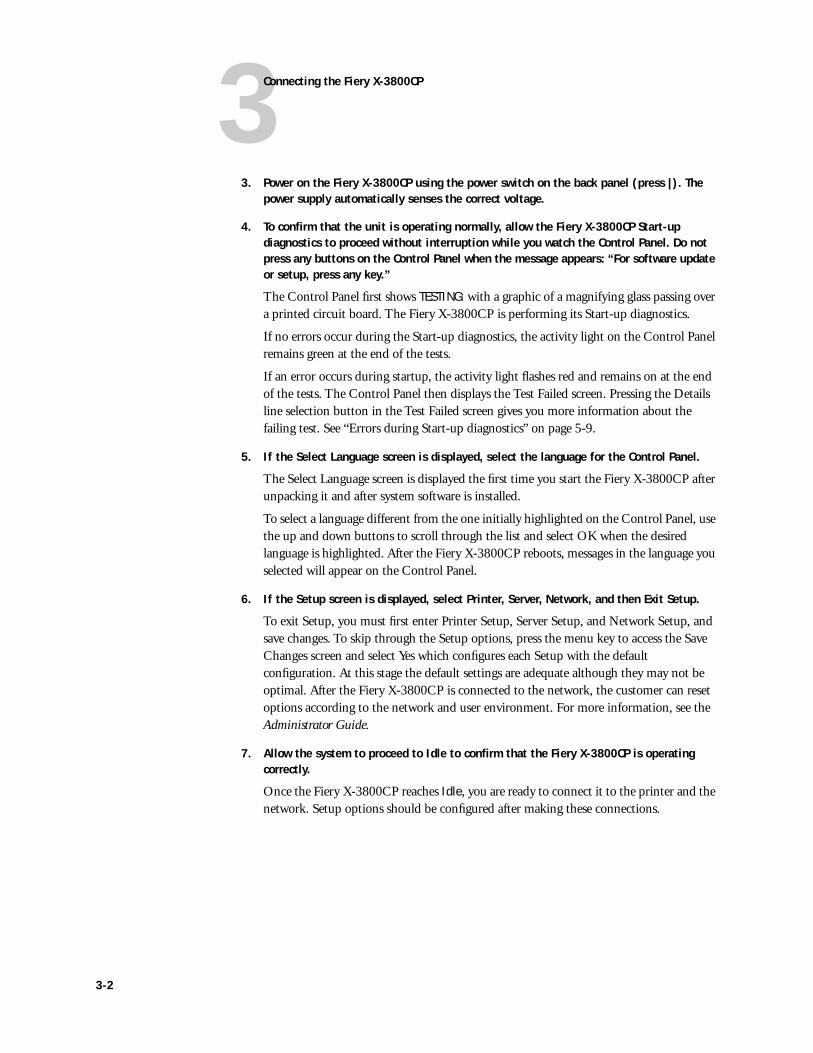
3. Power on the Fiery X-3800CP using the power switch on the back panel (press |). The power supply automatically senses the correct voltage.
4. To confirm that the unit is operating normally, allow the Fiery X-3800CP Start-up diagnostics to proceed without interruption while you watch the Control Panel. Do not press any buttons on the Control Panel when the message appears: “For software update or setup, press any key.”
The Control Panel first shows TESTING: with a graphic of a magnifying glass passing over a printed circuit board. The Fiery X-3800CP is performing its Start-up diagnostics.
If no errors occur during the Start-up diagnostics, the activity light on the Control Panel remains green at the end of the tests.
If an error occurs during startup, the activity light flashes red and remains on at the end of the tests. The Control Panel then displays the Test Failed screen. Pressing the Details line selection button in the Test Failed screen gives you more information about the failing test. See “Errors during Start-up diagnostics” on page 5-9.
5. If the Select Language screen is displayed, select the language for the Control Panel.
The Select Language screen is displayed the first time you start the Fiery X-3800CP after unpacking it and after system software is installed.
To select a language different from the one initially highlighted on the Control Panel, use the up and down buttons to scroll through the list and select OK when the desired language is highlighted. After the Fiery X-3800CP reboots, messages in the language you selected will appear on the Control Panel.
6. If the Setup screen is displayed, select Printer, Server, Network, and then Exit Setup.
To exit Setup, you must first enter Printer Setup, Server Setup, and Network Setup, and save changes. To skip through the Setup options, press the menu key to access the Save Changes screen and select Yes which configures each Setup with the default configuration. At this stage the default settings are adequate although they may not be optimal. After the Fiery X-3800CP is connected to the network, the customer can reset options according to the network and user environment. For more information, see the Administrator Guide.
7. Allow the system to proceed to Idle to confirm that the Fiery X-3800CP is operating correctly.
Once the Fiery X-3800CP reaches Idle, you are ready to connect it to the printer and the network. Setup options should be configured after making these connections.
3-2
3Connecting to the printer
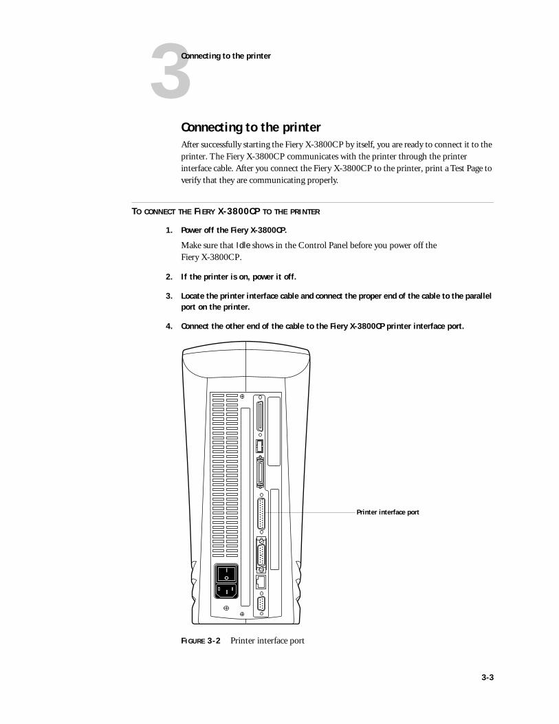
Connecting to the printerAfter successfully starting the Fiery X-3800CP by itself, you are ready to connect it to the printer. The Fiery X-3800CP communicates with the printer through the printer interface cable. After you connect the Fiery X-3800CP to the printer, print a Test Page to verify that they are communicating properly.
TO CONNECT THE FIERY X-3800CP TO THE PRINTER
1. Power off the Fiery X-3800CP.
Make sure that Idle shows in the Control Panel before you power off the Fiery X-3800CP.
2. If the printer is on, power it off.
3. Locate the printer interface cable and connect the proper end of the cable to the parallel port on the printer.
4. Connect the other end of the cable to the Fiery X-3800CP printer interface port.
FIGURE 3-2 Printer interface port
Printer interface port
3-3
3Connecting the Fiery X-3800CP
Printing the Fiery X-3800CP Test PageBefore connecting the Fiery X-3800CP to the network, print the Test Page to verify that it is connected properly to the printer. The Test Page is a color PostScript file that resides on the Fiery X-3800CP hard disk drive.
TO PRINT THE TEST PAGE FROM THE CONTROL PANEL
1. Power on the printer and allow it to warm up.
2. Power on the Fiery X-3800CP using the power switch on the back panel.
Messages will appear on the Control Panel as the Fiery X-3800CP runs through its Start-up diagnostics.
3. Before proceeding, make sure that the printer is not in use.
4. At the Idle screen, press the menu button (see “Using the Control Panel” on page 3-10). The Functions menu displays the options shown below:
5. Press the line selection button to the right of Print Pages and then select Test Page.
The Fiery X-3800CP sends the Test Page to the printer and displays the RIP and Print status screens so you can monitor the job.
6. Examine the quality of the Test Page from the printer.
The Test Page confirms that the Fiery X-3800CP print engine is functional and that the connection between the Fiery X-3800CP and the printer is good.
Print PagesReboot Server
Functions
Select
3-4
3Connecting to the network
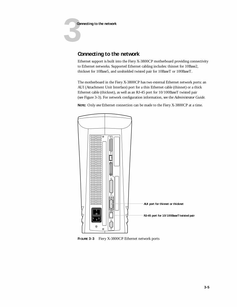
Connecting to the networkEthernet support is built into the Fiery X-3800CP motherboard providing connectivity to Ethernet networks. Supported Ethernet cabling includes: thinnet for 10Base2, thicknet for 10Base5, and unshielded twisted pair for 10BaseT or 100BaseT.
The motherboard in the Fiery X-3800CP has two external Ethernet network ports: an AUI (Attachment Unit Interface) port for a thin Ethernet cable (thinnet) or a thick Ethernet cable (thicknet), as well as an RJ-45 port for 10/100BaseT twisted pair (see Figure 3-3). For network configuration information, see the Administrator Guide.
NOTE: Only one Ethernet connection can be made to the Fiery X-3800CP at a time.
FIGURE 3-3 Fiery X-3800CP Ethernet network ports
AUI port for thinnet or thicknet
RJ-45 port for 10/100BaseT twisted pair
3-5
3Connecting the Fiery X-3800CP
TO CONNECT A THINNET OR THICKNET CABLE TO THE FIERY X-3800CP
1. Power off the Fiery X-3800CP before connecting it to any network device.
Make sure that the Info screen reads Idle. If the system has just finished processing, wait one minute after the system reaches the idle state before you power off the unit.
2. With the AUI slide latch in the open position, connect the network cable to the AUI port on the back of the Fiery X-3800CP. Slide the latch to lock the connector in place.
• To connect a 10Base2 thinnet cable to the Fiery X-3800CP, an Ethernet transceiver must be installed on the Fiery X-3800CP AUI port. The thinnet cable then connects to the BNC connector on the Ethernet transceiver.
If the transceiver has an SQE switch, make sure the switch is set to OFF.
• To connect a 10Base5 thicknet cable to the Fiery X-3800CP, connect the AUI drop cable directly to the AUI port on the back of the Fiery X-3800CP.
3. Configure Setup options.
It is the network administrator’s responsibility to configure Setup according to the network and user environment. Default settings in Setup are adequate although they may not be optimal for the user’s environment. Refer the network administrator to the Administrator Guide for Setup information.
4. After configuring Setup options, verify the network connection.
Once the network connection has been made and the Fiery X-3800CP has the correct Setup configuration and has reached the idle state, the Fiery X-3800CP should be available on the network.
The network administrator should perform any additional network Setup, verify the network connection, verify that the Fiery X-3800CP appears in the list of printers, and print a few test documents from a networked computer that will use the Fiery X-3800CP. (See the Administrator Guide for more information.)
3-6
3Connecting to the network
TO CONNECT A TWISTED PAIR CABLE TO THE FIERY X-3800CP
1. Power off the Fiery X-3800CP before connecting it to any network device.
Make sure that the Info screen reads Idle. If the system has just finished processing, wait one minute after the system reaches the idle state before you power off the unit.
2. Connect the network cable to the RJ-45 port on the back of the Fiery X-3800CP.
A Category 5 unshielded twisted pair (UTP) network cable must be used for 100BaseT.
3. Configure Setup options.
It is the network administrator’s responsibility to configure Setup according to the network and user environment. Default settings in Setup are adequate although they may not be optimal for the user’s environment. Refer the network administrator to the Administrator Guide for Setup information.
4. After configuring Setup options, verify the network connection.
Once the network connection has been made and the Fiery X-3800CP has the correct Setup configuration, the Fiery X-3800CP should be available on the network.
The network administrator should perform any additional Network setup, verify the network connection, verify that the Fiery X-3800CP appears in the list of printers, and print a few test documents from a networked computer that will use the Fiery X-3800CP. See the Administrator Guide for more information.
3-7
3Connecting the Fiery X-3800CP
Connecting a PC to the parallel portThe IEEE 1284-C parallel port on the back of the Fiery X-3800CP provides a high-speed interface for connecting directly to the parallel port of a stand-alone or networked PC through the parallel cable shipped with the Fiery X-3800CP.
TO CONNECT THE FIERY X-3800CP TO A PC
1. Power off the Fiery X-3800CP and the PC.
Make sure that the Info screen reads Idle. If the system has just finished processing, wait one minute after the system reaches the idle state before you power off the unit.
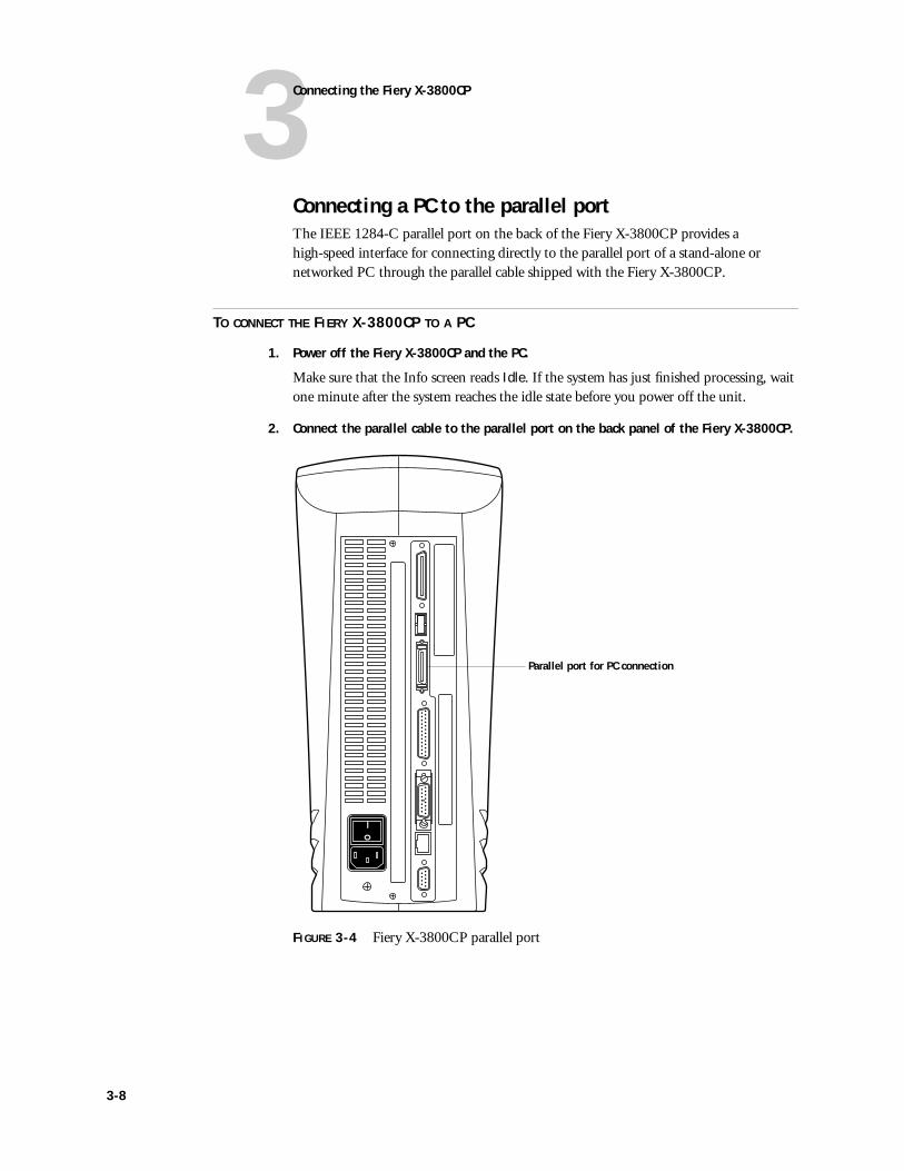
2. Connect the parallel cable to the parallel port on the back panel of the Fiery X-3800CP.
FIGURE 3-4 Fiery X-3800CP parallel port
Parallel port for PC connection
3-8
3Connecting a PC to the parallel port
3. Connect the other end of the parallel cable to the parallel port of the PC.
If there is more than one parallel port on the back of the PC, ask the network administrator to indicate the preferred parallel port to use for the Fiery X-3800CP.
NOTE: If the PC will be used for installing system software, make sure it meets the requirements specified in “Fiery X-3800CP system software” on page 4-40.
4. Power on the PC and the Fiery X-3800CP.
5. Configure Setup options.
It is the network administrator’s responsibility to configure Setup according to the network and user environment. Default settings in Setup are adequate although they may not be optimal for the user’s environment. Refer the network administrator to the Administrator Guide for Setup information.
6. After Setup options are configured, verify the parallel port connection.
Once the parallel port connection has been made and the Fiery X-3800CP has the correct Setup configuration and has reached the idle state, the network administrator should print a few test documents from the PC connected to the Fiery X-3800CP. See the Administrator Guide for more information.
3-9
3Connecting the Fiery X-3800CP
Using the Control PanelThis section describes the Control Panel on the front of the Fiery X-3800CP. Once you install the Fiery X-3800CP and verify that it starts up correctly, you can use the Control Panel to access and monitor different functions of the Fiery X-3800CP.
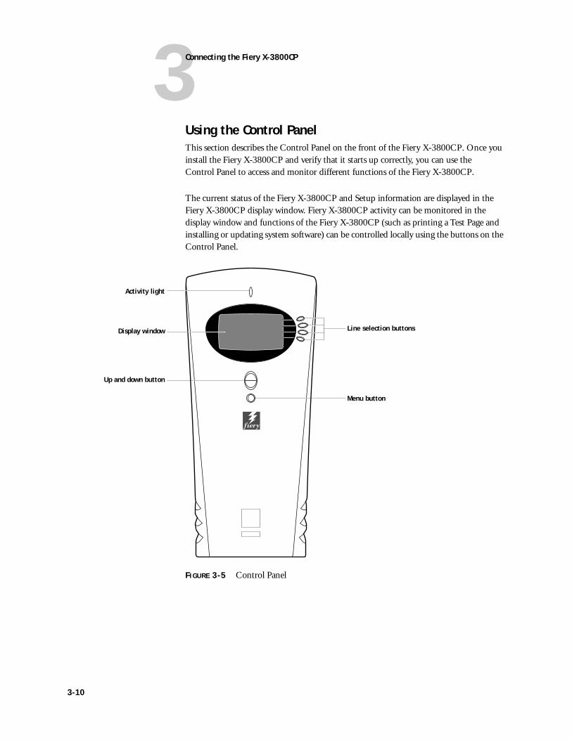
The current status of the Fiery X-3800CP and Setup information are displayed in the Fiery X-3800CP display window. Fiery X-3800CP activity can be monitored in the display window and functions of the Fiery X-3800CP (such as printing a Test Page and installing or updating system software) can be controlled locally using the buttons on the Control Panel.
FIGURE 3-5 Control Panel
Line selection buttons
Menu button
Activity light
Display window
Up and down button
3-10
3Using the Control Panel
Activity lightThe activity light indicates the current Fiery X-3800CP activity. If the light is:
Buttons
Solid red The Fiery X-3800CP has just been powered on and is about to begin Start-up diagnostics, or there is an error that prevents the Fiery X-3800CP from processing or printing.
Flashing red There is an error causing printing to be disabled, but the Fiery X-3800CP is still processing. When the error is cleared, the light changes to green.
Solid green The Fiery X-3800CP is idle.
Flashing green The Fiery X-3800CP is performing Start-up diagnostics, processing or printing a job, or communicating with a remote computer—for example, through Fiery Spooler.
No light The Fiery X-3800CP may be powered off or in Diagnostic Sets mode.
Line selection buttons
There are four line selection buttons on the right side of the Control Panel. Use these buttons to select the command displayed on the corresponding line of the display window. A special character pointing to a line selection button appears in the display window next to each command.
Up and down button
Use this button to scroll to different screens in multi-screen lists, to select Setup options from a list, and to select alphanumeric characters.
Menu button Press this button to view other display screens. There are several different display screens, showing different types of information about the Fiery X-3800CP.
▼
3-11
3Connecting the Fiery X-3800CP
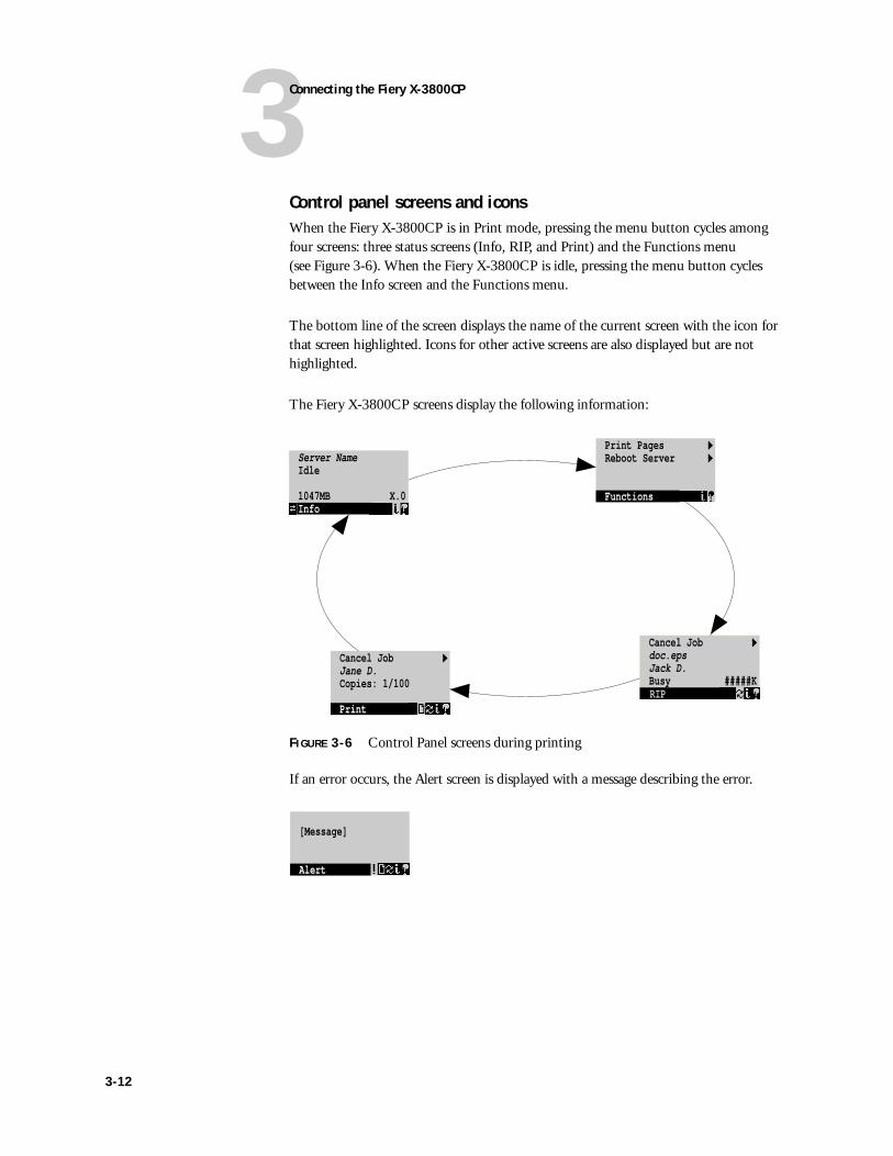
Control panel screens and iconsWhen the Fiery X-3800CP is in Print mode, pressing the menu button cycles among four screens: three status screens (Info, RIP, and Print) and the Functions menu (see Figure 3-6). When the Fiery X-3800CP is idle, pressing the menu button cycles between the Info screen and the Functions menu.
The bottom line of the screen displays the name of the current screen with the icon for that screen highlighted. Icons for other active screens are also displayed but are not highlighted.
The Fiery X-3800CP screens display the following information:
FIGURE 3-6 Control Panel screens during printing
If an error occurs, the Alert screen is displayed with a message describing the error.
Server NameIdle
1047MB X.0Info
Cancel Job >Jane D. Copies: 1/100
Print PagesReboot Server
Functions
Functions
Cancel Job >Job nameUser nameProcessed: bytesRIP
Cancel Job >doc.epsJack D.Busy #####KRIP
[Message]
Alert
3-12
3Using the Control Panel
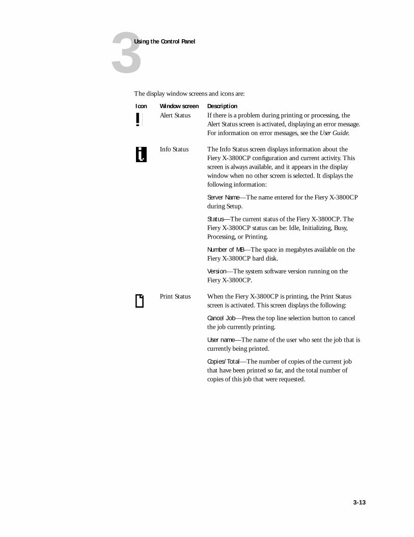
The display window screens and icons are:
Icon Window screen DescriptionAlert Status If there is a problem during printing or processing, the
Alert Status screen is activated, displaying an error message. For information on error messages, see the User Guide.
Info Status The Info Status screen displays information about the Fiery X-3800CP configuration and current activity. This screen is always available, and it appears in the display window when no other screen is selected. It displays the following information:
Server Name—The name entered for the Fiery X-3800CP during Setup.
Status—The current status of the Fiery X-3800CP. The Fiery X-3800CP status can be: Idle, Initializing, Busy, Processing, or Printing.
Number of MB—The space in megabytes available on the Fiery X-3800CP hard disk.
Version—The system software version running on the Fiery X-3800CP.
Print Status When the Fiery X-3800CP is printing, the Print Status screen is activated. This screen displays the following:
Cancel Job—Press the top line selection button to cancel the job currently printing.
User name—The name of the user who sent the job that is currently being printed.
Copies/Total—The number of copies of the current job that have been printed so far, and the total number of copies of this job that were requested.
3-13
3Connecting the Fiery X-3800CP
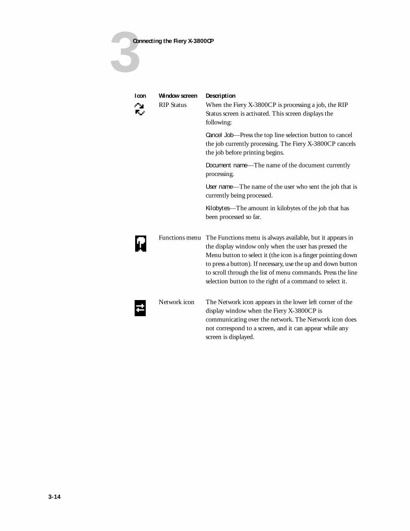
RIP Status When the Fiery X-3800CP is processing a job, the RIP Status screen is activated. This screen displays the following:
Cancel Job—Press the top line selection button to cancel the job currently processing. The Fiery X-3800CP cancels the job before printing begins.
Document name—The name of the document currently processing.
User name—The name of the user who sent the job that is currently being processed.
Kilobytes—The amount in kilobytes of the job that has been processed so far.
Functions menu The Functions menu is always available, but it appears in the display window only when the user has pressed the Menu button to select it (the icon is a finger pointing down to press a button). If necessary, use the up and down button to scroll through the list of menu commands. Press the line selection button to the right of a command to select it.
Network icon The Network icon appears in the lower left corner of the display window when the Fiery X-3800CP is communicating over the network. The Network icon does not correspond to a screen, and it can appear while any screen is displayed.
Icon Window screen Description
3-14
3Using the Control Panel
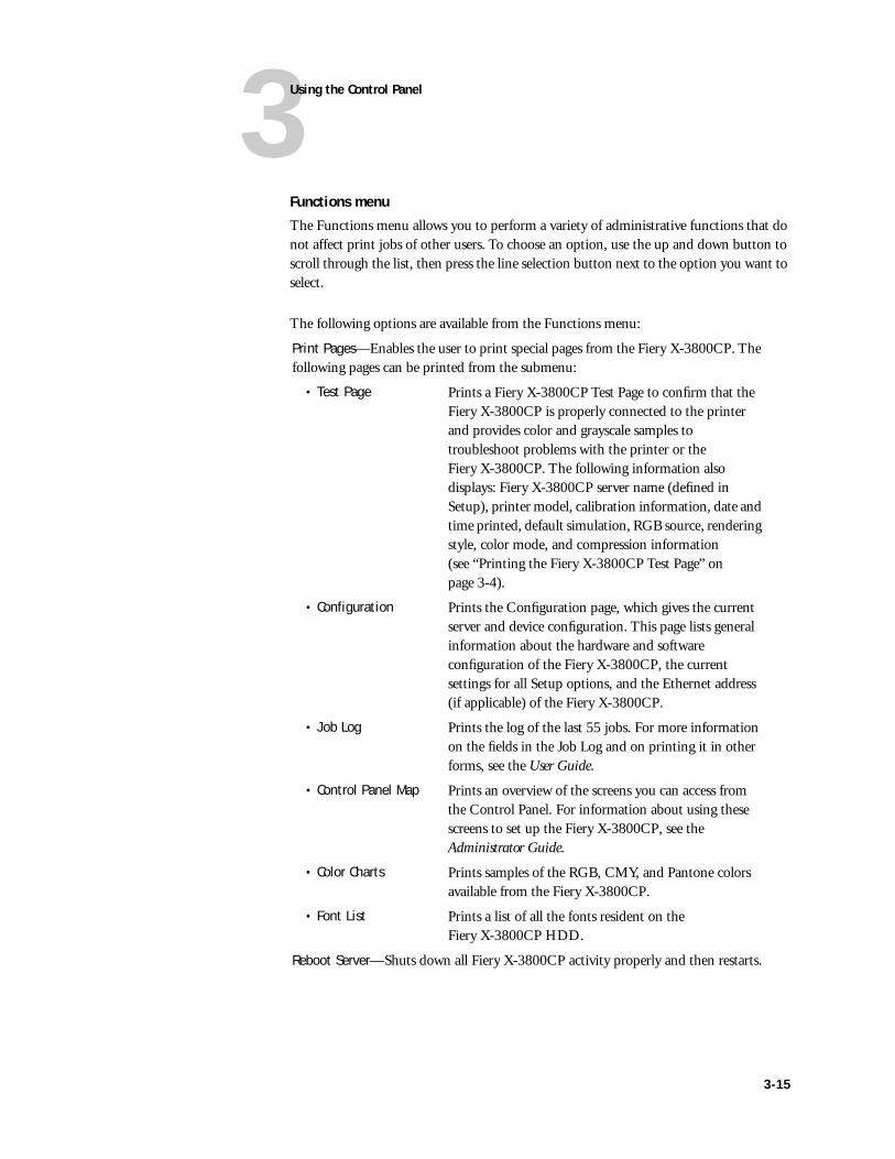
Functions menu
The Functions menu allows you to perform a variety of administrative functions that do not affect print jobs of other users. To choose an option, use the up and down button to scroll through the list, then press the line selection button next to the option you want to select.
The following options are available from the Functions menu:
Print Pages—Enables the user to print special pages from the Fiery X-3800CP. The following pages can be printed from the submenu:
• Test Page Prints a Fiery X-3800CP Test Page to confirm that the Fiery X-3800CP is properly connected to the printer and provides color and grayscale samples to troubleshoot problems with the printer or the Fiery X-3800CP. The following information also displays: Fiery X-3800CP server name (defined in Setup), printer model, calibration information, date and time printed, default simulation, RGB source, rendering style, color mode, and compression information (see “Printing the Fiery X-3800CP Test Page” on page 3-4).
• Configuration Prints the Configuration page, which gives the current server and device configuration. This page lists general information about the hardware and software configuration of the Fiery X-3800CP, the current settings for all Setup options, and the Ethernet address (if applicable) of the Fiery X-3800CP.
• Job Log Prints the log of the last 55 jobs. For more information on the fields in the Job Log and on printing it in other forms, see the User Guide.
• Control Panel Map Prints an overview of the screens you can access from the Control Panel. For information about using these screens to set up the Fiery X-3800CP, see the Administrator Guide.
• Color Charts Prints samples of the RGB, CMY, and Pantone colors available from the Fiery X-3800CP.
• Font List Prints a list of all the fonts resident on the Fiery X-3800CP HDD.
Reboot Server—Shuts down all Fiery X-3800CP activity properly and then restarts.
3-15
3Connecting the Fiery X-3800CP
Shutting down and restarting the Fiery X-3800CPThe Fiery X-3800CP will generally be left on all the time at the customer site. Remember that when the Fiery X-3800CP is powered off, network access to the printer is interrupted. Always obtain permission from the network administrator to take the Fiery X-3800CP off the network.
You should power off the Fiery X-3800CP when you need to service it or the printer, and before you remove or attach any cables to the Fiery X-3800CP.
TO SHUT DOWN THE FIERY X-3800CP
1. Make sure that the Fiery X-3800CP Info screen reads Idle.
When Printing or Ripping appears on the Control Panel, the Fiery X-3800CP is currently processing. Idle appears in the Info screen when the Fiery X-3800CP has finished processing.
2. Power off the Fiery X-3800CP using the power switch on the back panel.
If the system has just finished processing, wait one minute after the system reaches Idle before you power off the unit.
TO RESTART THE FIERY X-3800CP
1. If the Fiery X-3800CP is already on, ensure that it is not receiving, processing, or printing a document.
When Printing or Ripping appears on the Fiery X-3800CP Control Panel, the Fiery X-3800CP is currently processing a print job. Wait until the job is complete and Idle appears in the Info screen.
2. Press the menu button once, then select Reboot Server from the Functions menu. Otherwise, power on the Fiery X-3800CP using the power switch on the back panel.
3-16
4Overview
Generally, the Fiery X-3800CP requires no regular service or maintenance. Use the procedures in this chapter to inspect, remove, reseat, and replace major hardware components and install system software.
NOTE: Some procedures in this chapter are included for information only and are not required for Fiery X-3800CP systems.
OverviewThis chapter includes information on servicing the following components:
• Cable connections
• Circuit boards
• Replaceable parts on the motherboard (DIMMs, battery)
• Fans
• Power switch
• Power supply
• Hard disk drive (HDD)
• Front panel components
See Figure 4-1 on page 4-2 for an overview of components. Replacement parts are available from your authorized service representative.
Inside the chassis, the power supply is not encased. Before you service the Fiery X-3800CP, power it off completely and unplug the AC power cable from the back. When performing the service procedures described in this chapter, follow all precautions listed in “Precautions” on page xiii.
NOTE: The tools required to service the Fiery X-3800CP are listed in “Tools you will need” on page xv.
System software serviceFiery X-3800CP system software is installed on the HDD at the factory. Use the system software service kit to reinstall system software when you:
• Replace the HDD
• Replace the motherboard
• Upgrade to a more recent version of the system software
For information on installing system software, see “Fiery X-3800CP system software” on page 4-40.
Chapter 4: Service Procedures
4-1
4Service Procedures
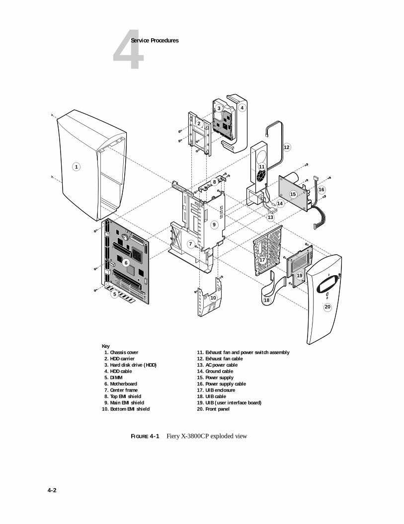
FIGURE 4-1 Fiery X-3800CP exploded view
Key1. Chassis cover 11. Exhaust fan and power switch assembly2. HDD carrier 12. Exhaust fan cable3. Hard disk drive (HDD) 13. AC power cable4. HDD cable 14. Ground cable5. DIMM 15. Power supply6. Motherboard 16. Power supply cable7. Center frame 17. UIB enclosure8. Top EMI shield 18. UIB cable9. Main EMI shield 19. UIB (user interface board)
10. Bottom EMI shield 20. Front panel
1
3 4
5
6
8
2
7
99
10
11
12
13
14
1516
17
19
2018
4-2
4Accessing internal components
Accessing internal componentsAlways use the following procedures when opening the Fiery X-3800CP chassis.
TO SHUT DOWN THE FIERY X-3800CP
1. Make sure that the Fiery X-3800CP Info screen reads Idle.
When Printing or Ripping appears on the Fiery X-3800CP Control Panel, the Fiery X-3800CP is currently processing. Idle appears in the Info screen when the Fiery X-3800CP has finished processing.
2. Power off the Fiery X-3800CP using the power switch on the back panel.
If the system has just finished processing, wait one minute after the system reaches the idle state before you power it off.
3. Disconnect all cables from the back of the Fiery ZX.
NOTE: Always obtain permission from the network administrator before you take the Fiery X-3800CP off the network.
4-3
4Service Procedures
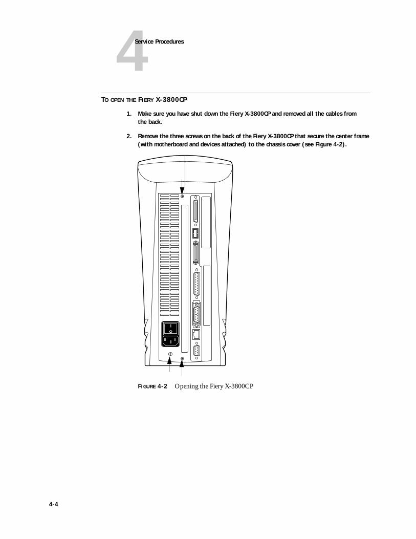
TO OPEN THE FIERY X-3800CP
1. Make sure you have shut down the Fiery X-3800CP and removed all the cables from the back.
2. Remove the three screws on the back of the Fiery X-3800CP that secure the center frame (with motherboard and devices attached) to the chassis cover (see Figure 4-2).
FIGURE 4-2 Opening the Fiery X-3800CP
4-4
4Accessing internal components
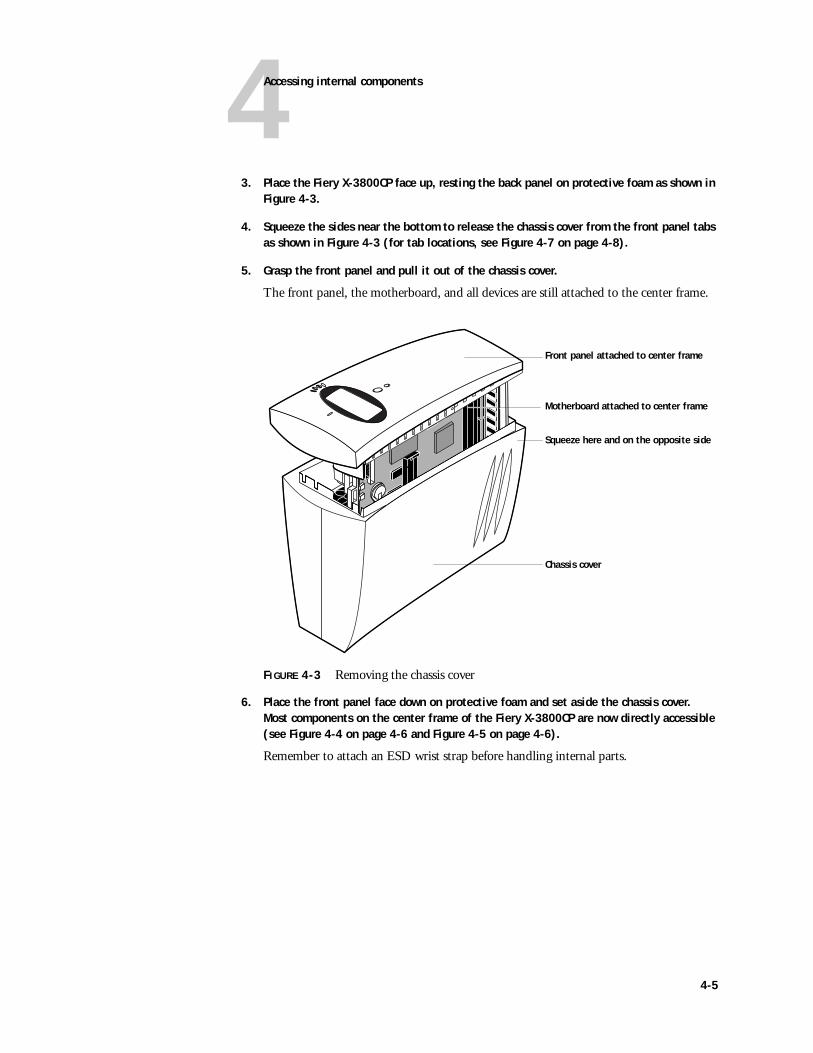
3. Place the Fiery X-3800CP face up, resting the back panel on protective foam as shown in Figure 4-3.
4. Squeeze the sides near the bottom to release the chassis cover from the front panel tabs as shown in Figure 4-3 (for tab locations, see Figure 4-7 on page 4-8).
5. Grasp the front panel and pull it out of the chassis cover.
The front panel, the motherboard, and all devices are still attached to the center frame.
FIGURE 4-3 Removing the chassis cover
6. Place the front panel face down on protective foam and set aside the chassis cover. Most components on the center frame of the Fiery X-3800CP are now directly accessible (see Figure 4-4 on page 4-6 and Figure 4-5 on page 4-6).
Remember to attach an ESD wrist strap before handling internal parts.
Front panel attached to center frame
Chassis cover
Motherboard attached to center frame
Squeeze here and on the opposite side
4-5
4Service Procedures
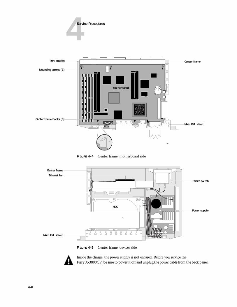
FIGURE 4-4 Center frame, motherboard side
FIGURE 4-5 Center frame, devices side
Inside the chassis, the power supply is not encased. Before you service the Fiery X-3800CP, be sure to power it off and unplug the power cable from the back panel.
Port bracket Center frame
Main EMI shield
Center frame hooks (3)
Mounting screws (3)
Motherboard
Power supply
Power switch
HDD
Center frame
Main EMI shield
Exhaust fan
4-6
4Accessing internal components
Accessing front panel componentsTo provide stability and easy access to components mounted on the center frame, removing the front panel is recommended so that the center frame can stand on its main EMI shield. It is not required to remove the front panel from the center frame except to gain access to front panel components and to replace the power supply. The following procedure describes how to remove the front panel.
TO REMOVE THE FRONT PANEL
1. Power off and open the Fiery X-3800CP as described on page 4-4.
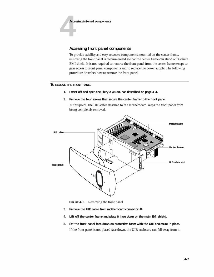
2. Remove the four screws that secure the center frame to the front panel.
At this point, the UIB cable attached to the motherboard keeps the front panel from being completely removed.
FIGURE 4-6 Removing the front panel
3. Remove the UIB cable from motherboard connector J4.
4. Lift off the center frame and place it face down on the main EMI shield.
5. Set the front panel face down on protective foam with the UIB enclosure in place.
If the front panel is not placed face down, the UIB enclosure can fall away from it.
UIB cable
Front panel
Motherboard
UIB cable slot
Center frame
4-7
4Service Procedures
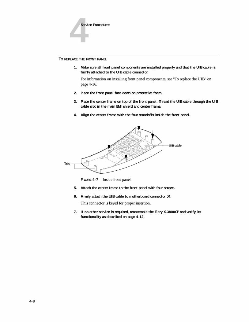
TO REPLACE THE FRONT PANEL
1. Make sure all front panel components are installed properly and that the UIB cable is firmly attached to the UIB cable connector.
For information on installing front panel components, see “To replace the UIB” on page 4-16.
2. Place the front panel face down on protective foam.
3. Place the center frame on top of the front panel. Thread the UIB cable through the UIB cable slot in the main EMI shield and center frame.
4. Align the center frame with the four standoffs inside the front panel.
FIGURE 4-7 Inside front panel
5. Attach the center frame to the front panel with four screws.
6. Firmly attach the UIB cable to motherboard connector J4.
This connector is keyed for proper insertion.
7. If no other service is required, reassemble the Fiery X-3800CP and verify its functionality as described on page 4-12.
Tabs
UIB cable
4-8
4Checking internal connections
Checking internal connectionsThe most common causes of hardware problems are faulty or loose connections. For example, a blank display screen on the Control Panel may be due to a disconnected UIB cable. Before you conclude that any board or component has failed, first remove, inspect, and reseat all appropriate connections, and then verify that the problem still occurs. See Figure 4-8 on page 4-10 for an overview of internal cable connections.
Before you touch any parts inside the Fiery X-3800CP chassis, attach an ESD wrist grounding strap. Touch the metal back panel of the Fiery X-3800CP to discharge static electricity.
TO CHECK BOARD AND CABLE CONNECTIONS
1. Power off and open the Fiery X-3800CP as described on page 4-4.
2. Inspect ribbon cables to make sure they are intact. Check the contact point between the cable and the connector to ensure that they have not separated.
Ribbon cables in the Fiery X-3800CP include the HDD cable and the UIB cable.
3. Make sure that cables are well seated on their connectors (see Figure 4-8 on page 4-10).
Connectors on the Fiery X-3800CP are keyed to fit only when cables are properly oriented.
4. After tightening connections, if one or more components are still not getting power, see “Power supply cable voltages” on page 4-33.
4-9
4Service Procedures
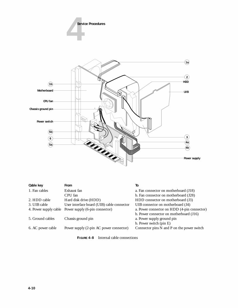
FIGURE 4-8 Internal cable connections
UIB
Chassis ground pin
Motherboard
Power supply
HDD
Power switch
1a
2
3
5b
6
5a4a
Cable key From To1. Fan cables Exhaust fan a. Fan connector on motherboard (J18)
CPU fan b. Fan connector on motherboard (J28)2. HDD cable Hard disk drive (HDD) HDD connector on motherboard (J3)3. UIB cable User interface board (UIB) cable connector UIB connector on motherboard (J4)4. Power supply cable Power supply (6-pin connector) a. Power connector on HDD (4-pin connector)
b. Power connector on motherboard (J16)5. Ground cables Chassis ground pin a. Power supply ground pin
b. Power switch (pin E)6. AC power cable Power supply (2-pin AC power connector) Connector pins N and P on the power switch
CPU fan
4b
1b
4-10
4Checking internal connections
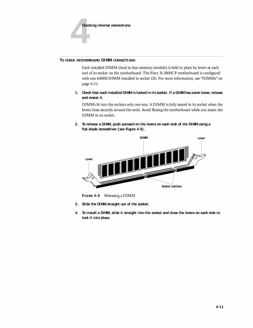
TO CHECK MOTHERBOARD DIMM CONNECTIONS
Each installed DIMM (dual in-line memory module) is held in place by levers at each end of its socket on the motherboard. The Fiery X-3800CP motherboard is configured with one 64MB DIMM installed in socket J26. For more information, see “DIMMs” on page 4-21.
1. Check that each installed DIMM is locked in its socket. If a DIMM has come loose, release and reseat it.
DIMMs fit into the sockets only one way. A DIMM is fully seated in its socket when the levers close securely around the ends. Avoid flexing the motherboard while you insert the DIMM in its socket.
2. To release a DIMM, push outward on the levers on each side of the DIMM using a flat-blade screwdriver (see Figure 4-9).
FIGURE 4-9 Releasing a DIMM
3. Slide the DIMM straight out of the socket.
4. To install a DIMM, slide it straight into the socket and close the levers on each side to lock it into place.
Lever
LeverDIMM
Socket notches
4-11
4Service Procedures
Restoring functionality after service
TO REASSEMBLE THE FIERY X-3800CP
1. Reseat all devices, boards, cables, connectors, and other parts loosened or removed during inspection or service.
2. Place the chassis cover on its back, so that it is open at the top.
3. If not already done, replace the front panel as described on page 4-8.
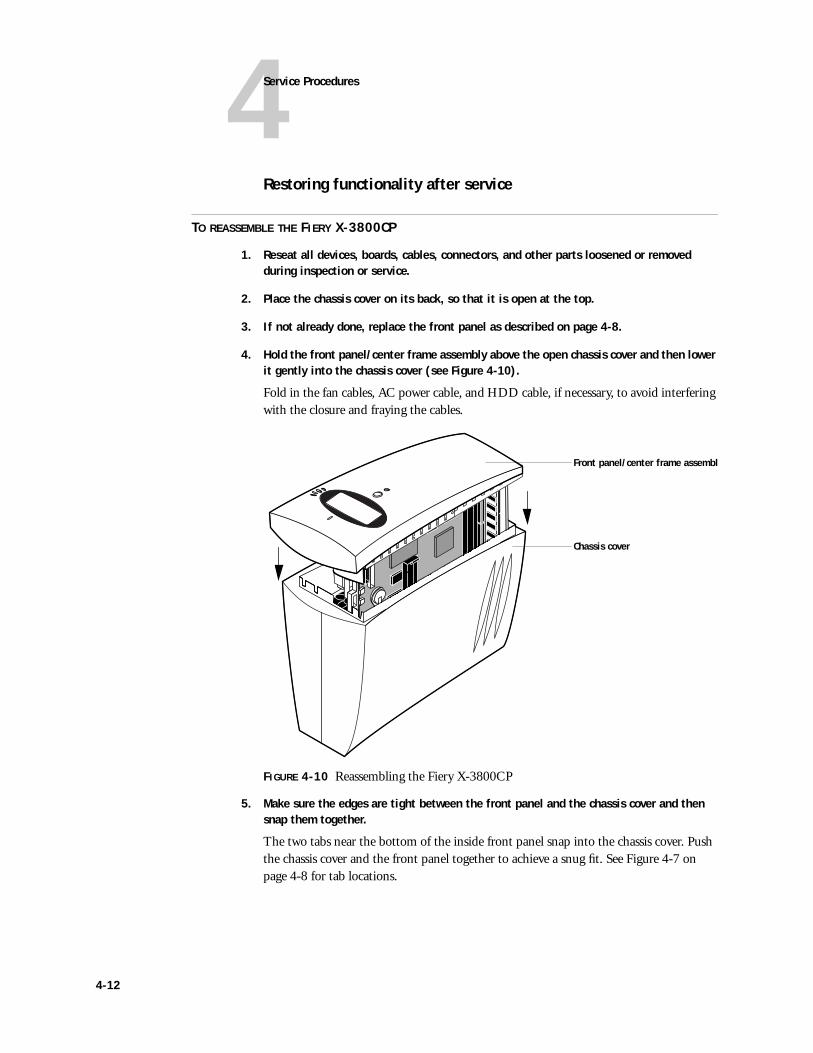
4. Hold the front panel/center frame assembly above the open chassis cover and then lower it gently into the chassis cover (see Figure 4-10).
Fold in the fan cables, AC power cable, and HDD cable, if necessary, to avoid interfering with the closure and fraying the cables.
FIGURE 4-10 Reassembling the Fiery X-3800CP
5. Make sure the edges are tight between the front panel and the chassis cover and then snap them together.
The two tabs near the bottom of the inside front panel snap into the chassis cover. Push the chassis cover and the front panel together to achieve a snug fit. See Figure 4-7 on page 4-8 for tab locations.
Front panel/center frame assembly
Chassis cover
4-12
4Checking internal connections
6. Place the Fiery X-3800CP in its standard operating position. Secure the chassis cover to the center frame with the three screws previously removed (see Figure 4-2 on page 4-4).
NOTE: Do not leave the chassis cover off after servicing. An air flow channel is created by the chassis cover and the fans. Leaving the chassis cover off could reduce the operational life expectancy of internal Fiery X-3800CP components.
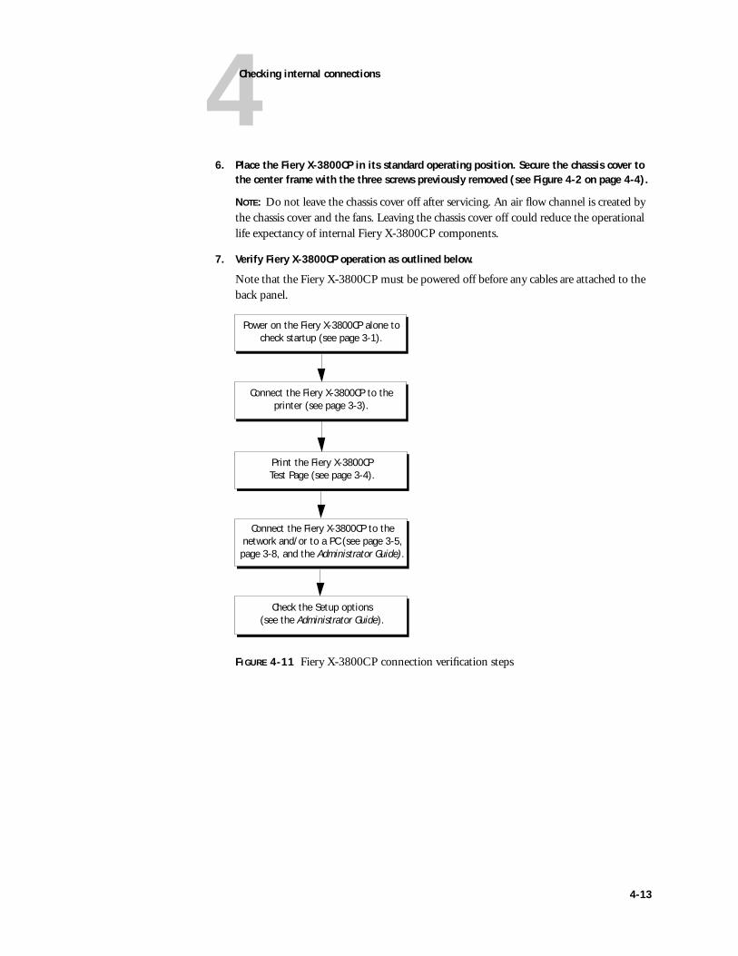
7. Verify Fiery X-3800CP operation as outlined below.
Note that the Fiery X-3800CP must be powered off before any cables are attached to the back panel.
FIGURE 4-11 Fiery X-3800CP connection verification steps
Print the Fiery X-3800CP Test Page (see page 3-4).
Connect the Fiery X-3800CP to the network and/or to a PC (see page 3-5, page 3-8, and the Administrator Guide).
Check the Setup options (see the Administrator Guide).
Power on the Fiery X-3800CP alone tocheck startup (see page 3-1).
Connect the Fiery X-3800CP to the printer (see page 3-3).
4-13
4Service Procedures
Removing and replacing circuit boardsThis section describes the procedure for removing and replacing the following boards:
• User interface board (UIB)
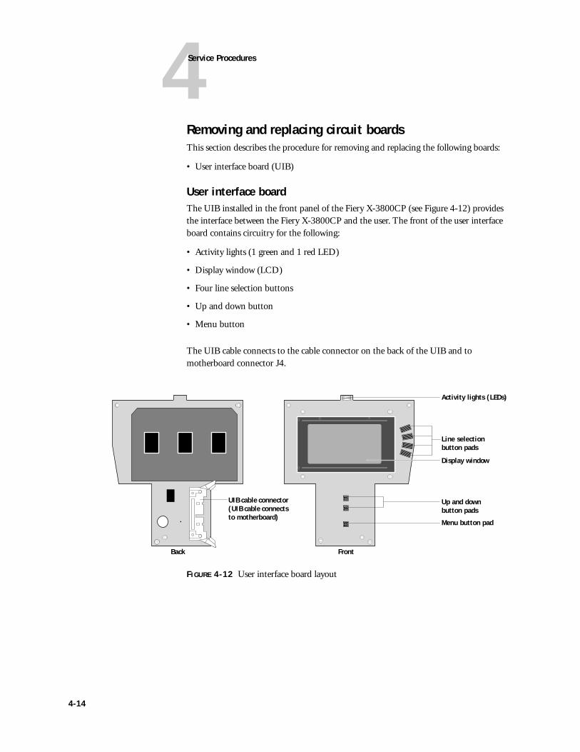
User interface boardThe UIB installed in the front panel of the Fiery X-3800CP (see Figure 4-12) provides the interface between the Fiery X-3800CP and the user. The front of the user interface board contains circuitry for the following:
• Activity lights (1 green and 1 red LED)
• Display window (LCD)
• Four line selection buttons
• Up and down button
• Menu button
The UIB cable connects to the cable connector on the back of the UIB and to motherboard connector J4.
FIGURE 4-12 User interface board layout
Display window
Menu button pad
Back Front
Up and down button pads
Activity lights (LEDs)
Line selection button pads
UIB cable connector (UIB cable connects to motherboard)
4-14
4Removing and replacing circuit boards
TO REMOVE THE UIB
1. Power off and open the Fiery X-3800CP as described on page 4-4.
2. Remove the front panel as described on page 4-7.
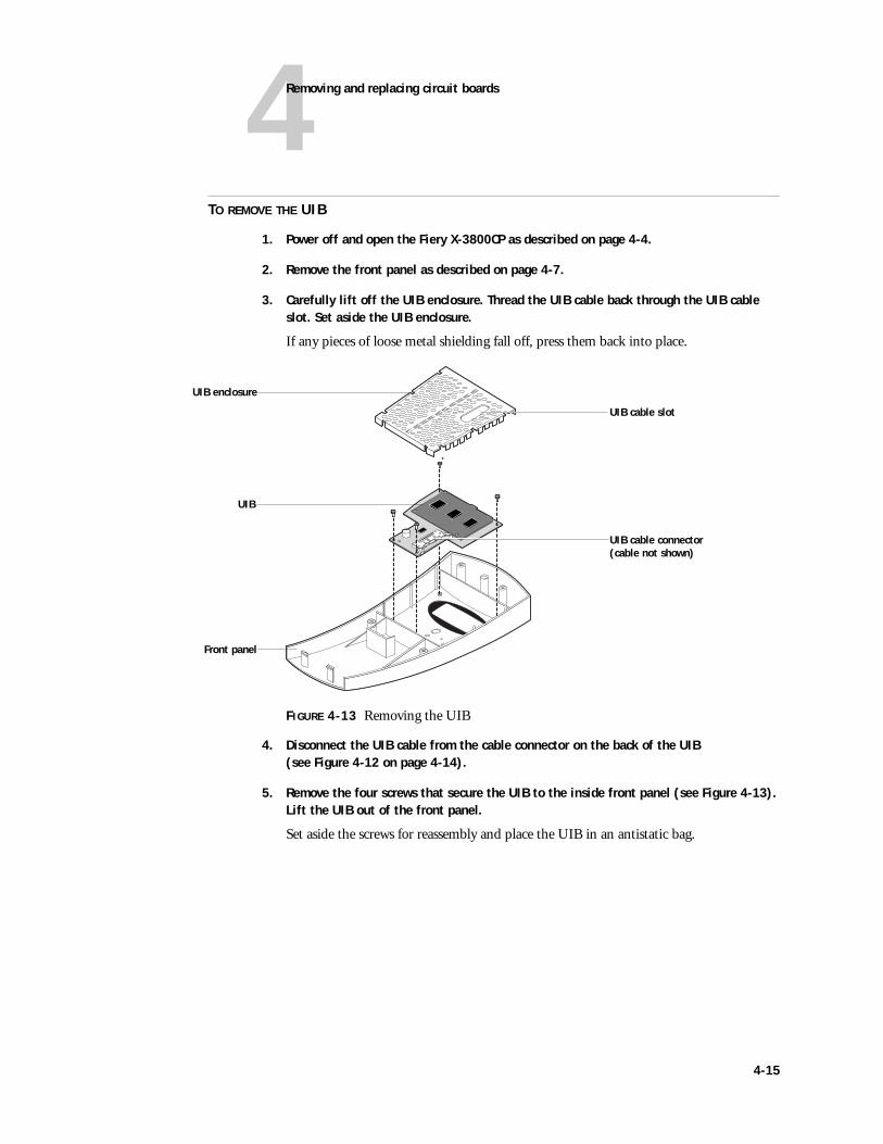
3. Carefully lift off the UIB enclosure. Thread the UIB cable back through the UIB cable slot. Set aside the UIB enclosure.
If any pieces of loose metal shielding fall off, press them back into place.
FIGURE 4-13 Removing the UIB
4. Disconnect the UIB cable from the cable connector on the back of the UIB (see Figure 4-12 on page 4-14).
5. Remove the four screws that secure the UIB to the inside front panel (see Figure 4-13). Lift the UIB out of the front panel.
Set aside the screws for reassembly and place the UIB in an antistatic bag.
UIB enclosure
UIB cable slot
UIB
Front panel
UIB cable connector (cable not shown)
4-15
4Service Procedures
TO REPLACE THE UIB
1. Place the UIB inside the front panel.
Make sure the buttons in the front panel stay in place. Also, make sure no dust or marks are on the display window glass of the UIB. See “Precautions” on page xiii.
2. Secure the UIB to the inside front panel with the four screws previously removed from the UIB.
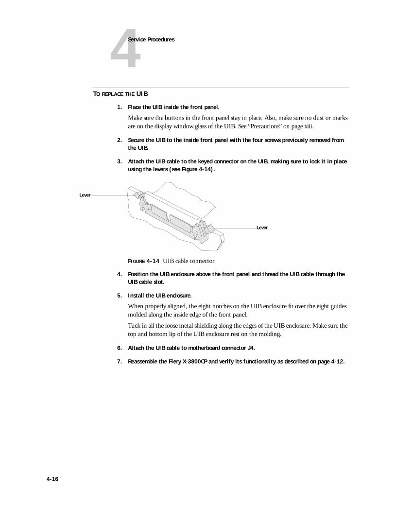
3. Attach the UIB cable to the keyed connector on the UIB, making sure to lock it in place using the levers (see Figure 4-14).
FIGURE 4-14 UIB cable connector
4. Position the UIB enclosure above the front panel and thread the UIB cable through the UIB cable slot.
5. Install the UIB enclosure.
When properly aligned, the eight notches on the UIB enclosure fit over the eight guides molded along the inside edge of the front panel.
Tuck in all the loose metal shielding along the edges of the UIB enclosure. Make sure the top and bottom lip of the UIB enclosure rest on the molding.
6. Attach the UIB cable to motherboard connector J4.
7. Reassemble the Fiery X-3800CP and verify its functionality as described on page 4-12.
Lever
Lever
4-16
4Removing and replacing circuit boards
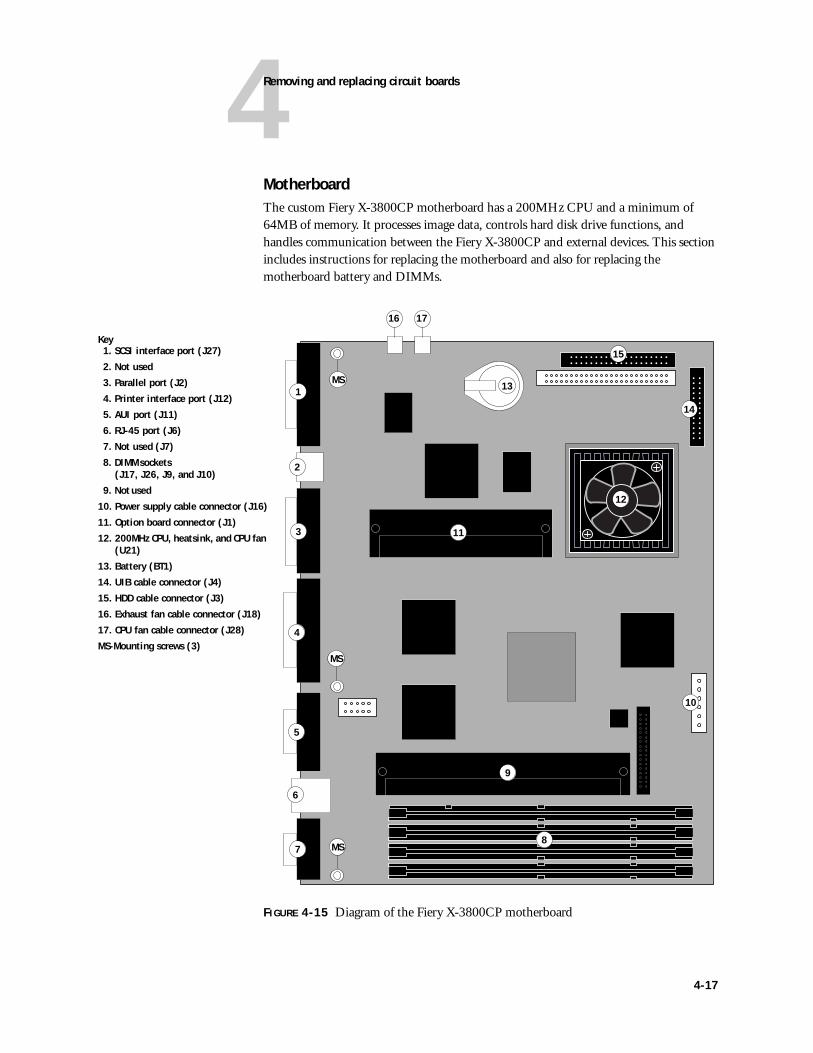
MotherboardThe custom Fiery X-3800CP motherboard has a 200MHz CPU and a minimum of 64MB of memory. It processes image data, controls hard disk drive functions, and handles communication between the Fiery X-3800CP and external devices. This section includes instructions for replacing the motherboard and also for replacing the motherboard battery and DIMMs.
FIGURE 4-15 Diagram of the Fiery X-3800CP motherboard
7
2
1
4
6
5
3
8
9
10
14
11
12
Key1. SCSI interface port (J27)
2. Not used
3. Parallel port (J2)
4. Printer interface port (J12)
5. AUI port (J11)
6. RJ-45 port (J6)
7. Not used (J7)
8. DIMM sockets (J17, J26, J9, and J10)
9. Not used
10. Power supply cable connector (J16)
11. Option board connector (J1)
12. 200MHz CPU, heatsink, and CPU fan (U21)
13. Battery (BT1)
14. UIB cable connector (J4)
15. HDD cable connector (J3)
16. Exhaust fan cable connector (J18)
17. CPU fan cable connector (J28)
MS-Mounting screws (3)
13MS
MS
MS
15
16 17
4-17
4Service Procedures
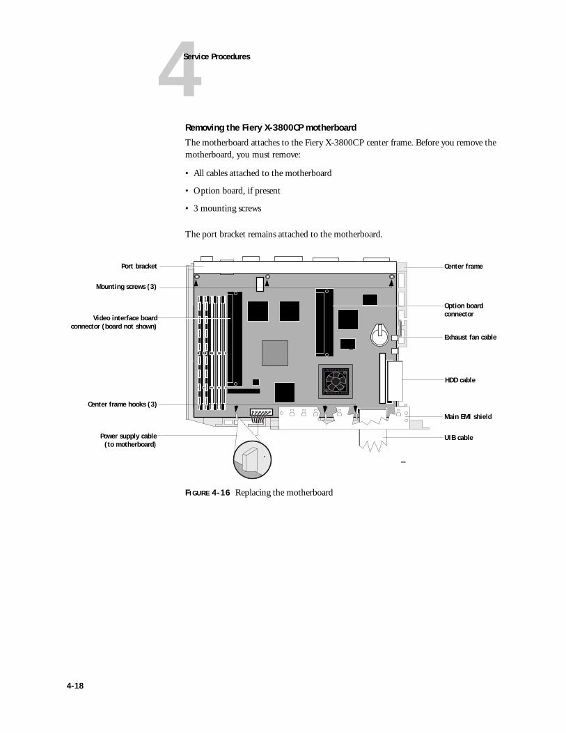
Removing the Fiery X-3800CP motherboard
The motherboard attaches to the Fiery X-3800CP center frame. Before you remove the motherboard, you must remove:
• All cables attached to the motherboard
• Option board, if present
• 3 mounting screws
The port bracket remains attached to the motherboard.
FIGURE 4-16 Replacing the motherboard
Port bracket
HDD cable
Exhaust fan cable
Center frame
Main EMI shield
UIB cable
Center frame hooks (3)
Mounting screws (3)
Video interface boardconnector (board not shown)
Power supply cable(to motherboard)
Option board connector
4-18
4Removing and replacing circuit boards
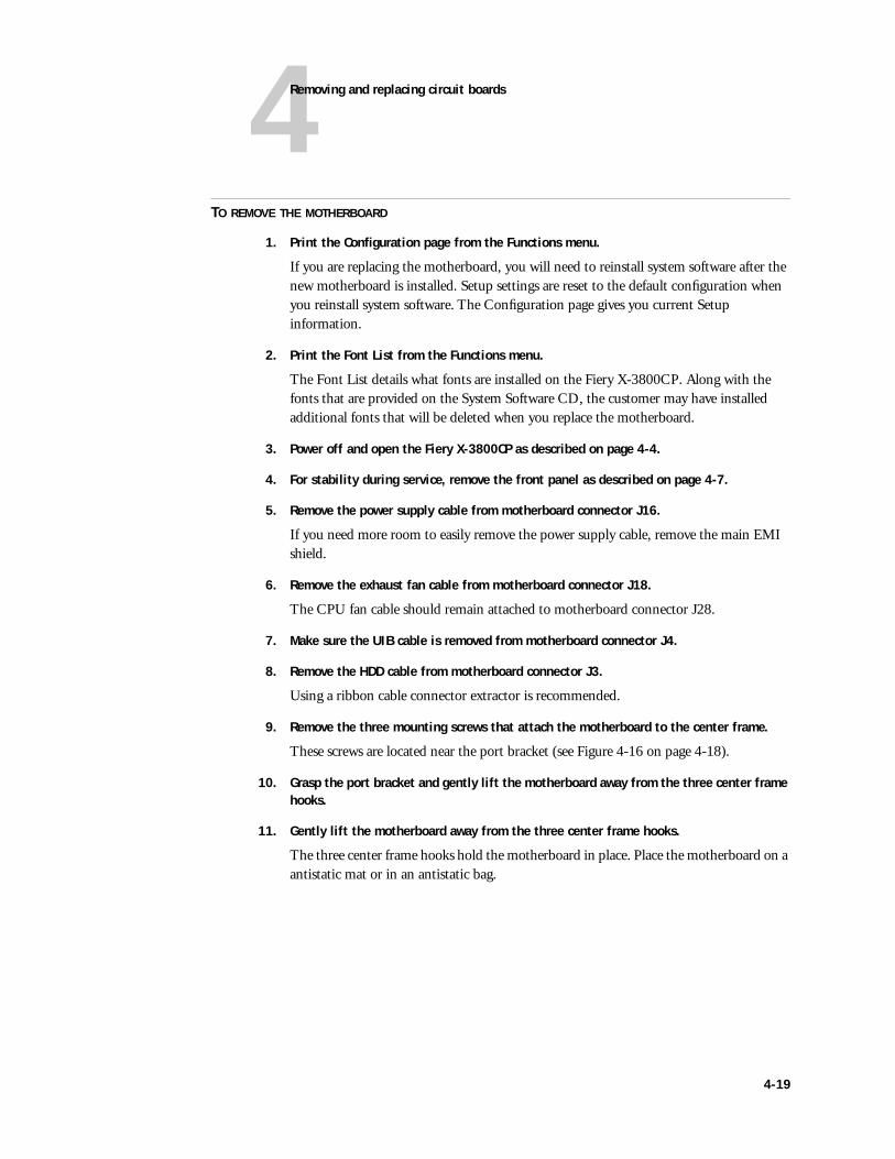
TO REMOVE THE MOTHERBOARD
1. Print the Configuration page from the Functions menu.
If you are replacing the motherboard, you will need to reinstall system software after the new motherboard is installed. Setup settings are reset to the default configuration when you reinstall system software. The Configuration page gives you current Setup information.
2. Print the Font List from the Functions menu.
The Font List details what fonts are installed on the Fiery X-3800CP. Along with the fonts that are provided on the System Software CD, the customer may have installed additional fonts that will be deleted when you replace the motherboard.
3. Power off and open the Fiery X-3800CP as described on page 4-4.
4. For stability during service, remove the front panel as described on page 4-7.
5. Remove the power supply cable from motherboard connector J16.
If you need more room to easily remove the power supply cable, remove the main EMI shield.
6. Remove the exhaust fan cable from motherboard connector J18.
The CPU fan cable should remain attached to motherboard connector J28.
7. Make sure the UIB cable is removed from motherboard connector J4.
8. Remove the HDD cable from motherboard connector J3.
Using a ribbon cable connector extractor is recommended.
9. Remove the three mounting screws that attach the motherboard to the center frame.
These screws are located near the port bracket (see Figure 4-16 on page 4-18).
10. Grasp the port bracket and gently lift the motherboard away from the three center frame hooks.
11. Gently lift the motherboard away from the three center frame hooks.
The three center frame hooks hold the motherboard in place. Place the motherboard on a antistatic mat or in an antistatic bag.
4-19
4Service Procedures
TO REPLACE THE MOTHERBOARD
1. Place the motherboard (with port bracket attached) into the center frame behind the three center frame hooks, making sure that the motherboard is in the correct position.
2. Secure the motherboard to the center frame with three mounting screws (see Figure 4-16 on page 4-18).
3. Connect the power supply cable to motherboard connector J16.
4. Attach the exhaust fan cable to motherboard connector J18.
The CPU fan cable should still be attached to connector J28.
5. Attach the UIB cable to motherboard connector J4.
6. Attach the HDD cable to motherboard connector J3.
7. Reattach the front panel as described page 4-8.
8. Reassemble the Fiery X-3800CP and verify its functionality as described on page 4-12.
9. If you installed a new motherboard, reinstall system software (see “Fiery X-3800CP system software” on page 4-40).
4-20
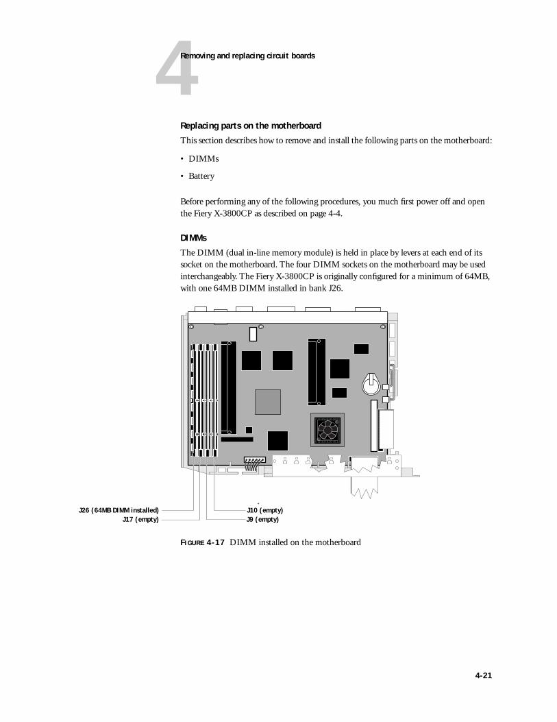
4Removing and replacing circuit boards
Replacing parts on the motherboard
This section describes how to remove and install the following parts on the motherboard:
• DIMMs
• Battery
Before performing any of the following procedures, you much first power off and open the Fiery X-3800CP as described on page 4-4.
DIMMs
The DIMM (dual in-line memory module) is held in place by levers at each end of its socket on the motherboard. The four DIMM sockets on the motherboard may be used interchangeably. The Fiery X-3800CP is originally configured for a minimum of 64MB, with one 64MB DIMM installed in bank J26.
FIGURE 4-17 DIMM installed on the motherboard
J26 (64MB DIMM installed) J10 (empty)J9 (empty)J17 (empty)
4-21
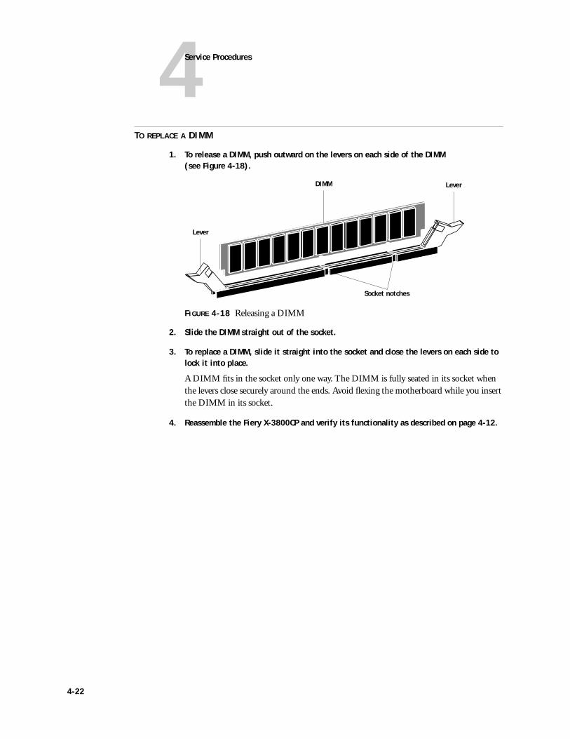
4Service Procedures
TO REPLACE A DIMM
1. To release a DIMM, push outward on the levers on each side of the DIMM (see Figure 4-18).
FIGURE 4-18 Releasing a DIMM
2. Slide the DIMM straight out of the socket.
3. To replace a DIMM, slide it straight into the socket and close the levers on each side to lock it into place.
A DIMM fits in the socket only one way. The DIMM is fully seated in its socket when the levers close securely around the ends. Avoid flexing the motherboard while you insert the DIMM in its socket.
4. Reassemble the Fiery X-3800CP and verify its functionality as described on page 4-12.
Lever
LeverDIMM
Socket notches
4-22
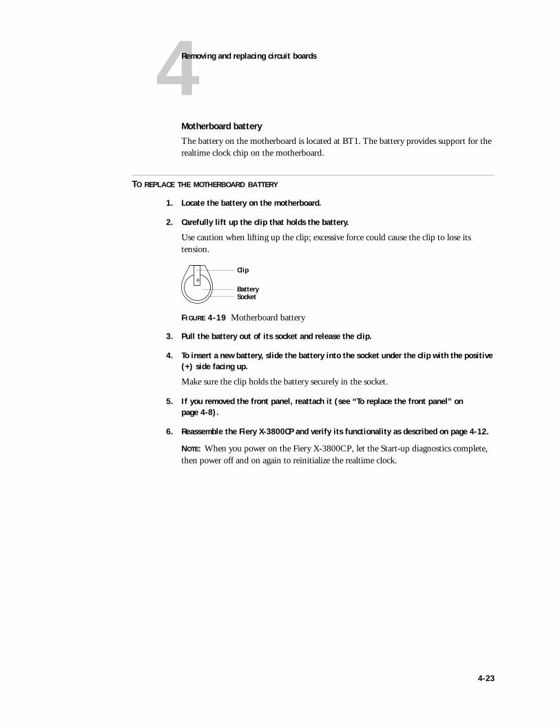
4Removing and replacing circuit boards
Motherboard battery
The battery on the motherboard is located at BT1. The battery provides support for the realtime clock chip on the motherboard.
TO REPLACE THE MOTHERBOARD BATTERY
1. Locate the battery on the motherboard.
2. Carefully lift up the clip that holds the battery.
Use caution when lifting up the clip; excessive force could cause the clip to lose its tension.
FIGURE 4-19 Motherboard battery
3. Pull the battery out of its socket and release the clip.
4. To insert a new battery, slide the battery into the socket under the clip with the positive (+) side facing up.
Make sure the clip holds the battery securely in the socket.
5. If you removed the front panel, reattach it (see “To replace the front panel” on page 4-8).
6. Reassemble the Fiery X-3800CP and verify its functionality as described on page 4-12.
NOTE: When you power on the Fiery X-3800CP, let the Start-up diagnostics complete, then power off and on again to reinitialize the realtime clock.
Clip
BatterySocket
+
4-23
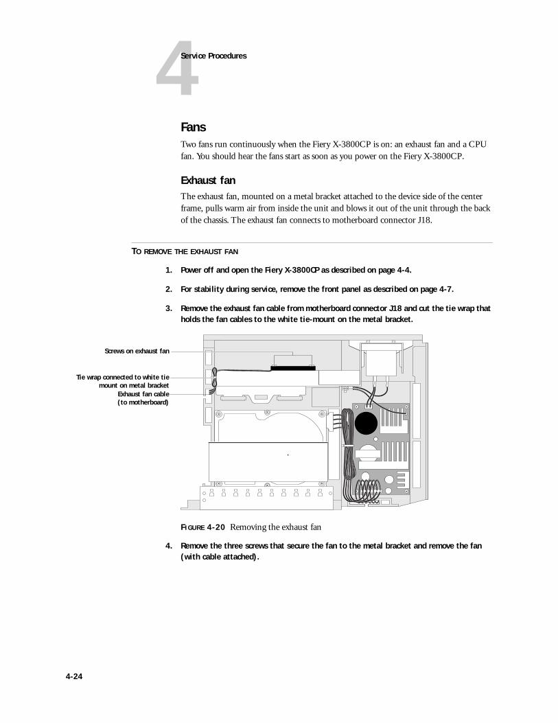
4Service Procedures
FansTwo fans run continuously when the Fiery X-3800CP is on: an exhaust fan and a CPU fan. You should hear the fans start as soon as you power on the Fiery X-3800CP.
Exhaust fanThe exhaust fan, mounted on a metal bracket attached to the device side of the center frame, pulls warm air from inside the unit and blows it out of the unit through the back of the chassis. The exhaust fan connects to motherboard connector J18.
TO REMOVE THE EXHAUST FAN
1. Power off and open the Fiery X-3800CP as described on page 4-4.
2. For stability during service, remove the front panel as described on page 4-7.
3. Remove the exhaust fan cable from motherboard connector J18 and cut the tie wrap that holds the fan cables to the white tie-mount on the metal bracket.
FIGURE 4-20 Removing the exhaust fan
4. Remove the three screws that secure the fan to the metal bracket and remove the fan (with cable attached).
Tie wrap connected to white tiemount on metal bracket
Screws on exhaust fan
Exhaust fan cable(to motherboard)
4-24
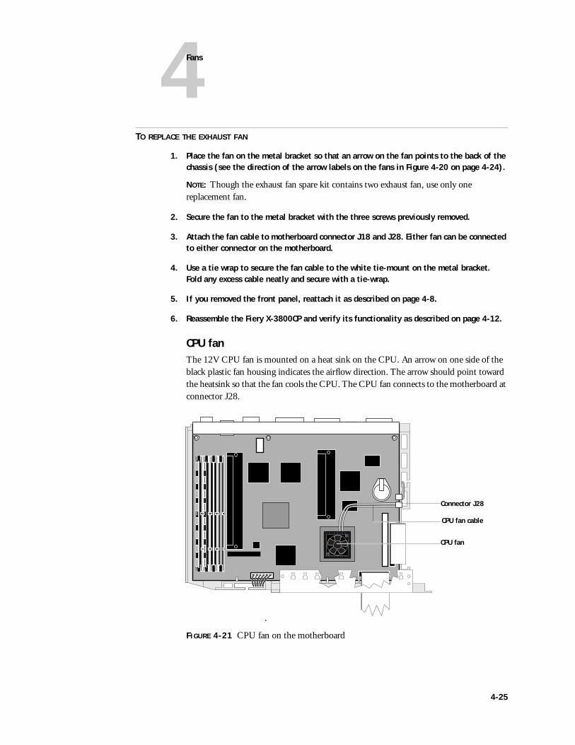
4Fans
TO REPLACE THE EXHAUST FAN
1. Place the fan on the metal bracket so that an arrow on the fan points to the back of the chassis (see the direction of the arrow labels on the fans in Figure 4-20 on page 4-24).
NOTE: Though the exhaust fan spare kit contains two exhaust fan, use only one replacement fan.
2. Secure the fan to the metal bracket with the three screws previously removed.
3. Attach the fan cable to motherboard connector J18 and J28. Either fan can be connected to either connector on the motherboard.
4. Use a tie wrap to secure the fan cable to the white tie-mount on the metal bracket. Fold any excess cable neatly and secure with a tie-wrap.
5. If you removed the front panel, reattach it as described on page 4-8.
6. Reassemble the Fiery X-3800CP and verify its functionality as described on page 4-12.
CPU fanThe 12V CPU fan is mounted on a heat sink on the CPU. An arrow on one side of the black plastic fan housing indicates the airflow direction. The arrow should point toward the heatsink so that the fan cools the CPU. The CPU fan connects to the motherboard at connector J28.
FIGURE 4-21 CPU fan on the motherboard
Connector J28
CPU fan cable
CPU fan
4-25
4Service Procedures
TO REMOVE THE CPU FAN
1. Power off and open the Fiery X-3800CP as described on page 4-4.
2. Unplug the CPU fan cable from Fiery X-3800CP board connector J28 (see Figure 4-21 on page 4-25).
To remove the fan cable, gently pull the white connector from the pins.
3. Using a Phillips screwdriver, remove the two screws that fasten the CPU fan to the CPU heatsink. Set aside the screws so that you can replace them later.
Do not apply excessive pressure to the board when replacing the two screws.
4. Remove the CPU fan and set it aside.
TO REPLACE THE CPU FAN
1. Position the CPU fan on top of the CPU heatsink so that one arrow on the fan is pointing down to the heatsink.
2. Attach the CPU fan to the CPU heatsink with two screws.
Do not to apply excessive pressure to the board when replacing the screws.
3. Connect the CPU fan cable to Fiery X-3800CP board connector J28.
4. Reassemble the Fiery X-3800CP and verify its functionality as described on page 4-12.
4-26
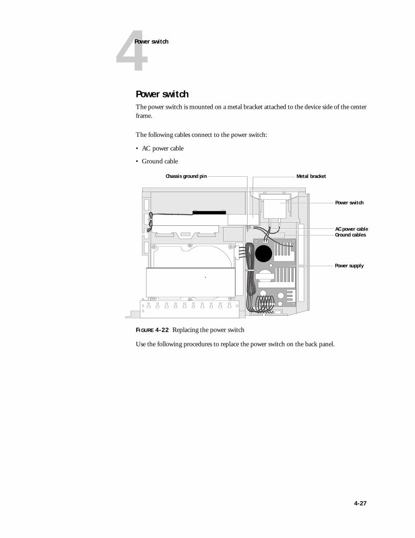
4Power switch
Power switchThe power switch is mounted on a metal bracket attached to the device side of the center frame.
The following cables connect to the power switch:
• AC power cable
• Ground cable
FIGURE 4-22 Replacing the power switch
Use the following procedures to replace the power switch on the back panel.
Metal bracket
Power switch
Power supply
Chassis ground pin
Ground cablesAC power cable
4-27
4Service Procedures
TO REMOVE THE POWER SWITCH
1. Power off and open the Fiery X-3800CP as described on page 4-4.
2. For stability during service, remove the front panel as described on page 4-7.
3. Note the orientation of the power switch and the cables attached to the power switch for reassembly.
When the Fiery X-3800CP is in its standard operating position, the on/off switch is above the power connector.
4. Using a pair of needlenose pliers, carefully remove the AC power cable (blue and brown cables) from the pins on the power switch.
Leave the other end of the cable attached to the power supply.
5. Remove the ground cable (green) from its pin on the power switch (see Figure 4-22 on page 4-27).
Leave the other end of the cable attached to the chassis ground pin.
6. Remove the two screws that secure the power switch to the metal bracket.
7. Remove the ground shield.
8. Remove the power switch by lifting it up through the opening in the metal bracket.
TO REPLACE THE POWER SWITCH
1. Slide the power switch down through the opening in the metal bracket. Position the power switch so the silkscreened | is on top when the Fiery X-3800CP is in its standard operating position.
2. Place the ground shield over the power switch.
3. Secure the power switch and ground shield to the metal bracket with two screws.
4-28
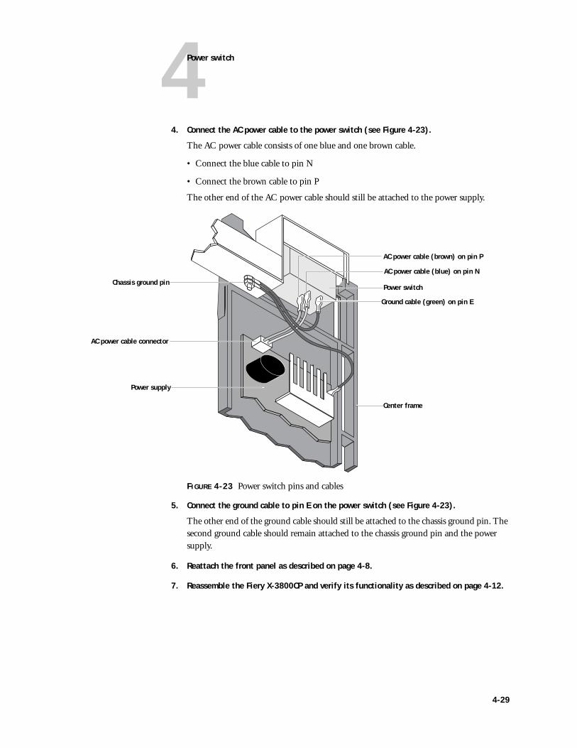
4Power switch
4. Connect the AC power cable to the power switch (see Figure 4-23).
The AC power cable consists of one blue and one brown cable.
• Connect the blue cable to pin N
• Connect the brown cable to pin P
The other end of the AC power cable should still be attached to the power supply.
FIGURE 4-23 Power switch pins and cables
5. Connect the ground cable to pin E on the power switch (see Figure 4-23).
The other end of the ground cable should still be attached to the chassis ground pin. The second ground cable should remain attached to the chassis ground pin and the power supply.
6. Reattach the front panel as described on page 4-8.
7. Reassemble the Fiery X-3800CP and verify its functionality as described on page 4-12.
Ground cable (green) on pin E
Power supply
Chassis ground pin
AC power cable connector
Power switch
AC power cable (blue) on pin N
AC power cable (brown) on pin P
Center frame
4-29
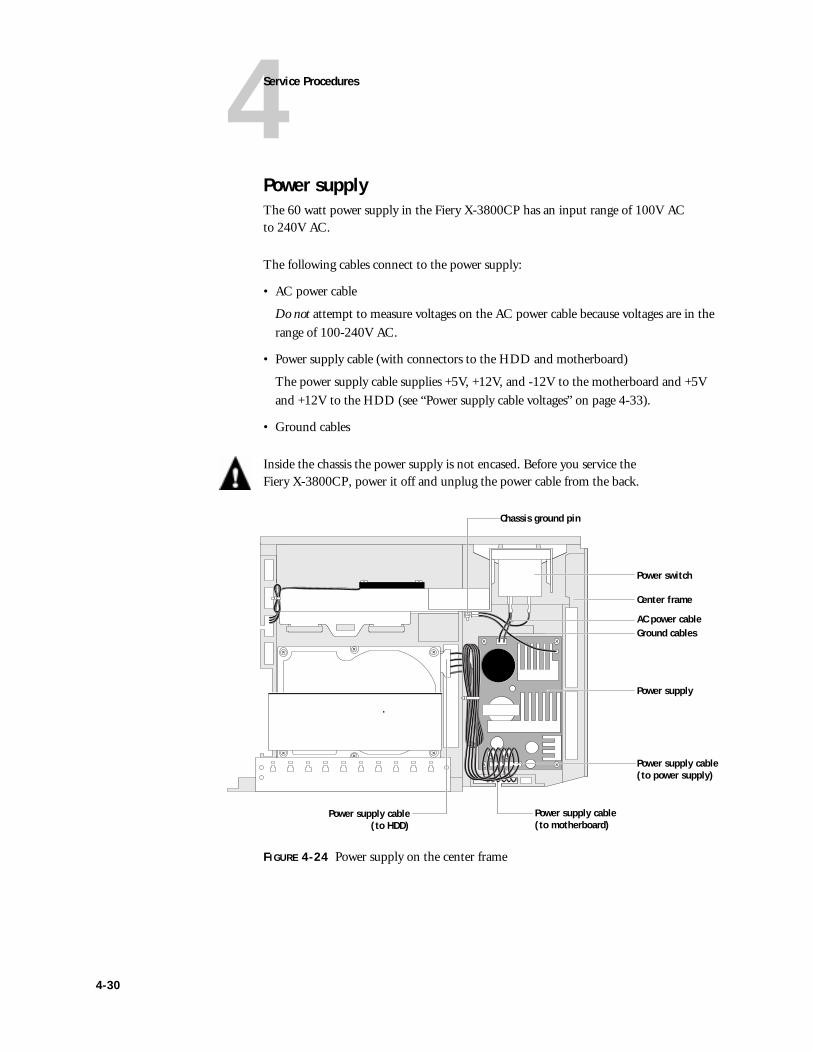
4Service Procedures
Power supplyThe 60 watt power supply in the Fiery X-3800CP has an input range of 100V AC to 240V AC.
The following cables connect to the power supply:
• AC power cable
Do not attempt to measure voltages on the AC power cable because voltages are in the range of 100-240V AC.
• Power supply cable (with connectors to the HDD and motherboard)
The power supply cable supplies +5V, +12V, and -12V to the motherboard and +5V and +12V to the HDD (see “Power supply cable voltages” on page 4-33).
• Ground cables
Inside the chassis the power supply is not encased. Before you service the Fiery X-3800CP, power it off and unplug the power cable from the back.
FIGURE 4-24 Power supply on the center frame
Power switch
Center frame
Power supply
Chassis ground pin
Ground cablesAC power cable
Power supply cable (to motherboard)
Power supply cable(to HDD)
Power supply cable (to power supply)
4-30
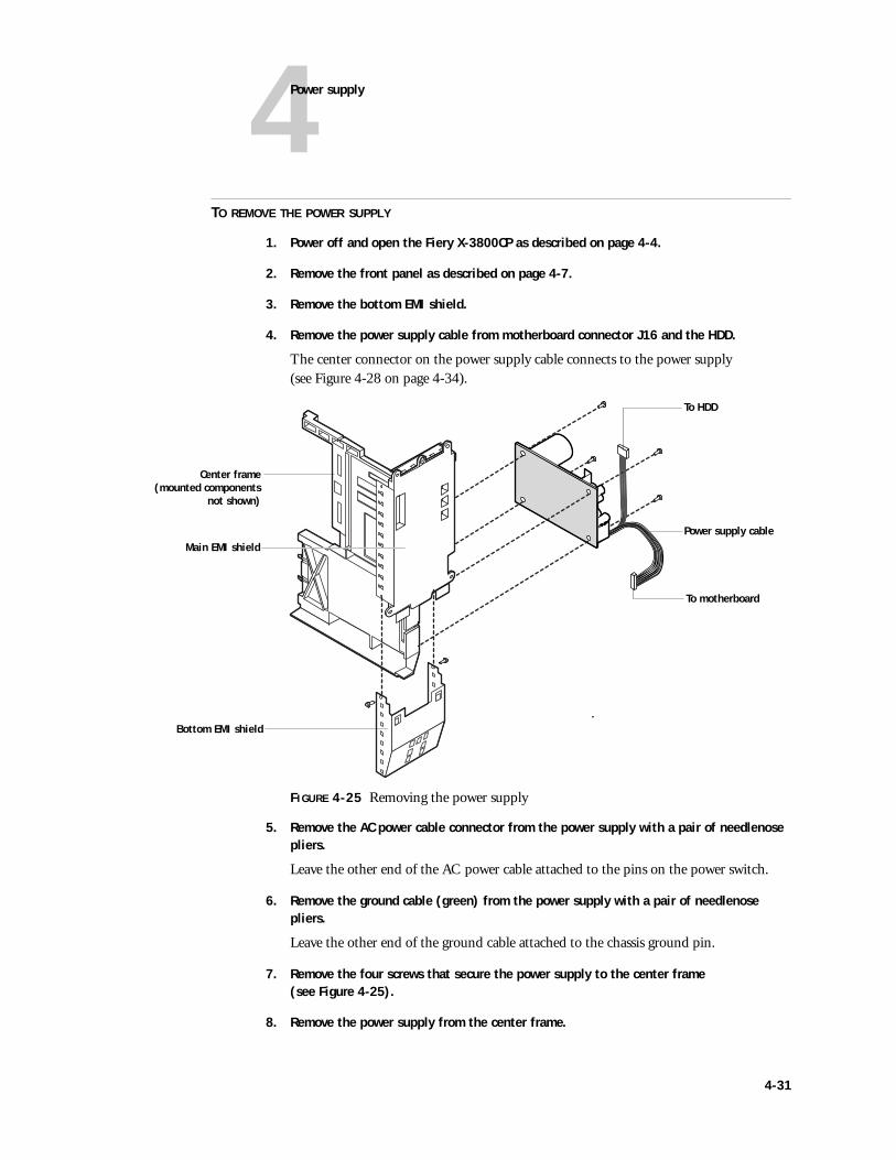
4Power supply
TO REMOVE THE POWER SUPPLY
1. Power off and open the Fiery X-3800CP as described on page 4-4.
2. Remove the front panel as described on page 4-7.
3. Remove the bottom EMI shield.
4. Remove the power supply cable from motherboard connector J16 and the HDD.
The center connector on the power supply cable connects to the power supply (see Figure 4-28 on page 4-34).
FIGURE 4-25 Removing the power supply
5. Remove the AC power cable connector from the power supply with a pair of needlenose pliers.
Leave the other end of the AC power cable attached to the pins on the power switch.
6. Remove the ground cable (green) from the power supply with a pair of needlenose pliers.
Leave the other end of the ground cable attached to the chassis ground pin.
7. Remove the four screws that secure the power supply to the center frame (see Figure 4-25).
8. Remove the power supply from the center frame.
Center frame(mounted components
not shown)
To HDD
To motherboard
Power supply cableMain EMI shield
Bottom EMI shield
4-31
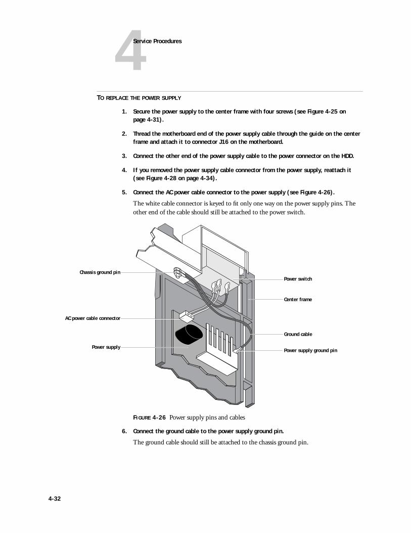
4Service Procedures
TO REPLACE THE POWER SUPPLY
1. Secure the power supply to the center frame with four screws (see Figure 4-25 on page 4-31).
2. Thread the motherboard end of the power supply cable through the guide on the center frame and attach it to connector J16 on the motherboard.
3. Connect the other end of the power supply cable to the power connector on the HDD.
4. If you removed the power supply cable connector from the power supply, reattach it (see Figure 4-28 on page 4-34).
5. Connect the AC power cable connector to the power supply (see Figure 4-26).
The white cable connector is keyed to fit only one way on the power supply pins. The other end of the cable should still be attached to the power switch.
FIGURE 4-26 Power supply pins and cables
6. Connect the ground cable to the power supply ground pin.
The ground cable should still be attached to the chassis ground pin.
Power switch
Power supply
Chassis ground pin
AC power cable connector
Ground cable
Center frame
Power supply ground pin
4-32
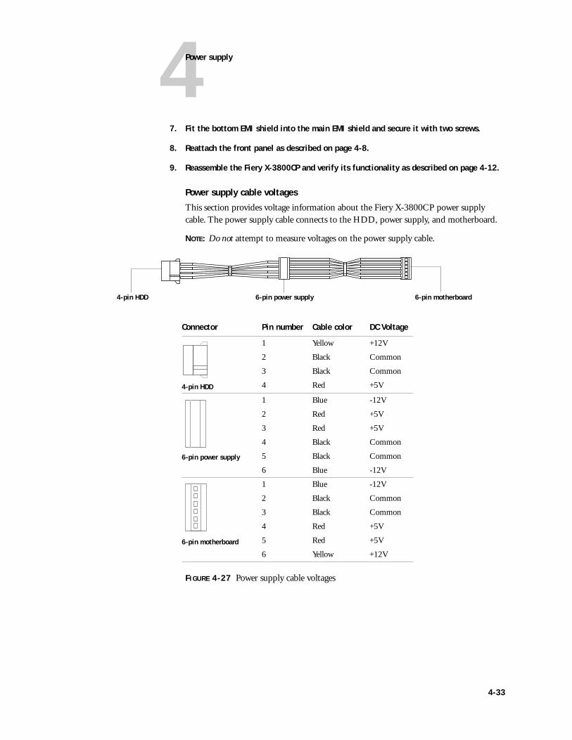
4Power supply
7. Fit the bottom EMI shield into the main EMI shield and secure it with two screws.
8. Reattach the front panel as described on page 4-8.
9. Reassemble the Fiery X-3800CP and verify its functionality as described on page 4-12.
Power supply cable voltages
This section provides voltage information about the Fiery X-3800CP power supply cable. The power supply cable connects to the HDD, power supply, and motherboard.
NOTE: Do not attempt to measure voltages on the power supply cable.
FIGURE 4-27 Power supply cable voltages
Connector Pin number Cable color DC Voltage
4-pin HDD
1 Yellow +12V
2 Black Common
3 Black Common
4 Red +5V
6-pin power supply
1 Blue -12V
2 Red +5V
3 Red +5V
4 Black Common
5 Black Common
6 Blue -12V
6-pin motherboard
1 Blue -12V
2 Black Common
3 Black Common
4 Red +5V
5 Red +5V
6 Yellow +12V
4-pin HDD 6-pin motherboard6-pin power supply
4-33
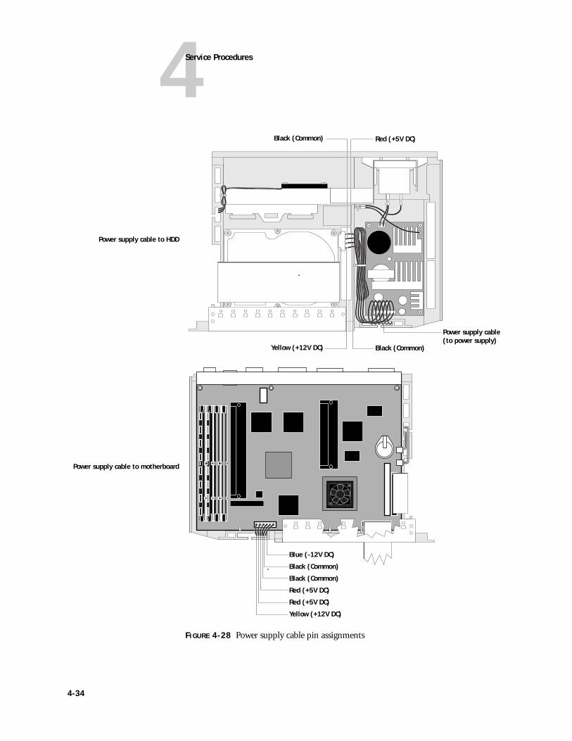
4Service Procedures
FIGURE 4-28 Power supply cable pin assignments
Power supply cable to HDD
Power supply cable(to power supply)
Yellow (+12V DC) Black (Common)
Red (+5V DC)Black (Common)
Power supply cable to motherboard
Yellow (+12V DC)
Red (+5V DC)
Red (+5V DC)
Black (Common)
Black (Common)
Blue (-12V DC)
4-34
4Hard disk drive
Hard disk driveThe factory-installed hard disk drive (HDD) is formatted and loaded with all Fiery X-3800CP software, including operating software, system software, network drivers, and printer fonts. Because the HDD is used to store spooled print jobs, available disk space is displayed on the Control Panel.
If you are replacing the HDD, you need:
• The appropriate System Software CD and documentation
• The latest version of the user software (for computers that print to the Fiery X-3800CP)
Proper handling
Handle the hard disk drive with care:
• Use proper ESD practices when grounding yourself and the Fiery X-3800CP.
• Keep magnets and magnetic-sensitive objects away from the HDD.
• Do not remove the six screws on top of the HDD. Loosening these screws voids the warranty.
• Never drop, jar, or bump the HDD.
• Handle the HDD by its sides and avoid touching the printed circuit board assembly.
• Allow the HDD to reach room temperature before installation.
• Never connect live cables to the HDD.
TO REMOVE THE HDD
1. If possible, print the Configuration page from the Functions menu to record the customer’s Setup configuration.
If you are replacing the HDD, Setup settings will be lost. The Configuration page gives you the customer’s Setup configuration so it can be reenterd later.
2. Print the Font List from the Functions menu.
The Font List details what fonts are resident on the Fiery X-3800CP HDD. Along with the fonts that are provided on the System Software CD, the customer may have installed additional fonts that will be lost when the HDD is replaced.
3. Power off and open the Fiery X-3800CP as described on page 4-4.
4. For stability during service, remove the front panel as described on page 4-7.
4-35
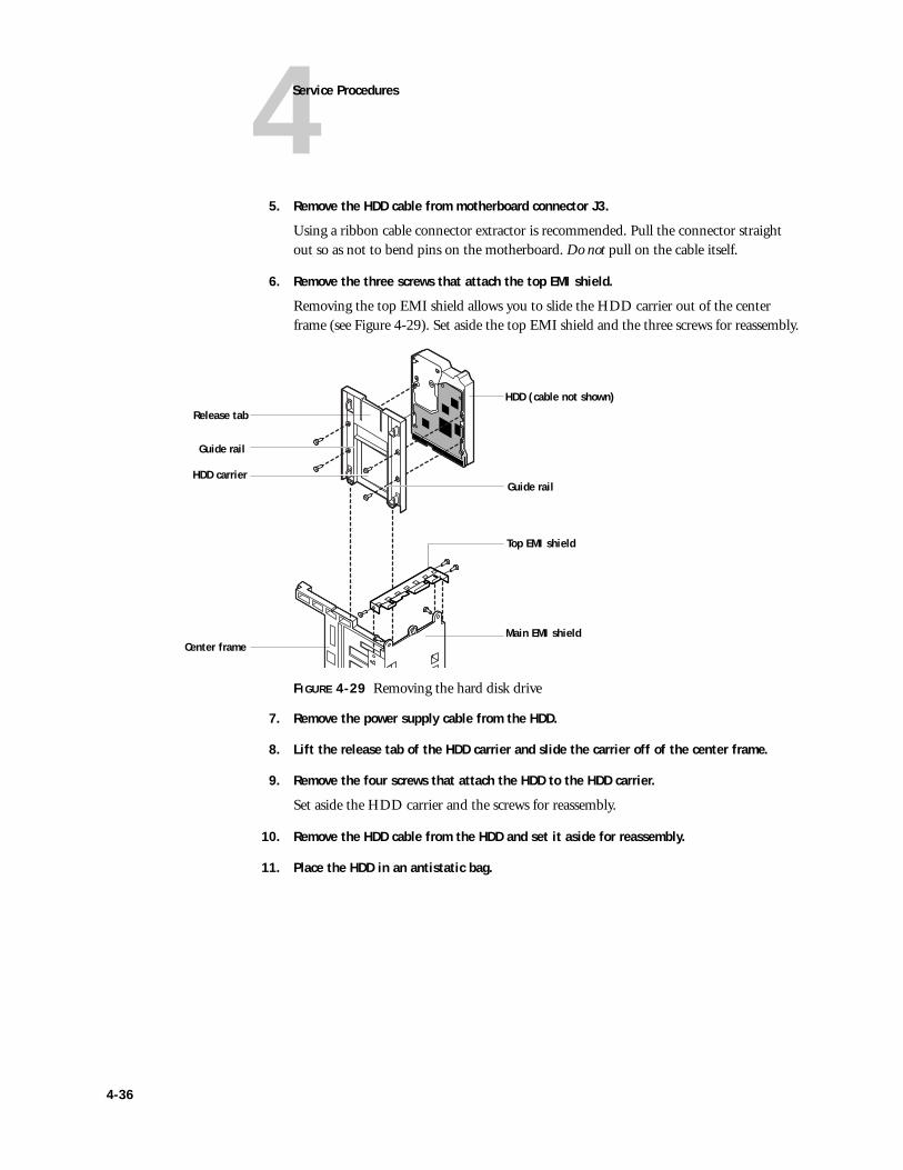
4Service Procedures
5. Remove the HDD cable from motherboard connector J3.
Using a ribbon cable connector extractor is recommended. Pull the connector straight out so as not to bend pins on the motherboard. Do not pull on the cable itself.
6. Remove the three screws that attach the top EMI shield.
Removing the top EMI shield allows you to slide the HDD carrier out of the center frame (see Figure 4-29). Set aside the top EMI shield and the three screws for reassembly.
FIGURE 4-29 Removing the hard disk drive
7. Remove the power supply cable from the HDD.
8. Lift the release tab of the HDD carrier and slide the carrier off of the center frame.
9. Remove the four screws that attach the HDD to the HDD carrier.
Set aside the HDD carrier and the screws for reassembly.
10. Remove the HDD cable from the HDD and set it aside for reassembly.
11. Place the HDD in an antistatic bag.
Top EMI shield
Main EMI shield
Release tab
HDD (cable not shown)
Guide rail
Center frame
HDD carrierGuide rail
4-36

4Hard disk drive
TO REPLACE THE HDD
1. Attach the HDD cable to the HDD and drape it over the top of the HDD.
Even though they are keyed, the connectors on the HDD cable are identical. Make sure to connect the cable such that the red wire (pin 1) is nearest the middle of the HDD when the cable is draped over the top of the HDD.
2. Position the HDD on the HDD carrier and secure with four screws (see Figure 4-29 on page 4-36).
The bottom of the HDD connects to the side of the HDD carrier without the guide rails. HDD connectors are oriented away from the release tab on the HDD carrier.
3. Slide the HDD carrier along the guide rails on the center frame.
To make it easier to connect the cable, slide the HDD carrier in only part way.
4. Attach the power supply cable to the HDD.
5. Continue sliding the HDD carrier onto the center frame until the release tab clicks into place.
6. Attach the HDD cable to motherboard connector J3. Align the connectors and push the HDD cable connector straight in to avoid bending pins on the motherboard.
Straighten any bent pins with a pair of needlenose pliers.
7. Secure the top EMI shield to the main EMI shield with three screws.
Keep any loose metal shielding pressed in place.
8. If you removed the front panel, reattach it as described on page 4-8.
9. Reassemble the Fiery X-3800CP and verify its functionality as described on page 4-12.
10. If you replaced the HDD with a new drive, install system software (see “Fiery X-3800CP system software” on page 4-40).
4-37
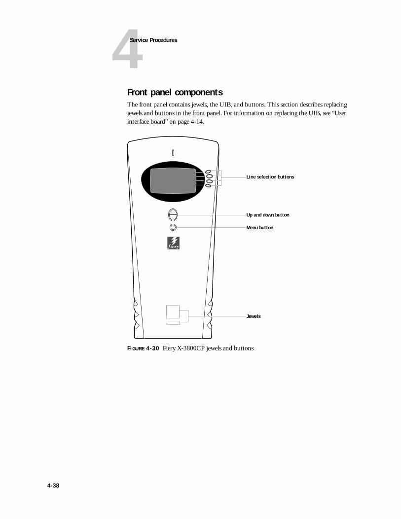
4Service Procedures
Front panel componentsThe front panel contains jewels, the UIB, and buttons. This section describes replacing jewels and buttons in the front panel. For information on replacing the UIB, see “User interface board” on page 4-14.
FIGURE 4-30 Fiery X-3800CP jewels and buttons
Jewels
Line selection buttons
Up and down button
Menu button
4-38
4Front panel components
JewelsSome upgrades or product modifications may require you to replace a jewel on the front panel of the Fiery X-3800CP. The following procedure describes how to replace the jewels.
TO REPLACE A JEWEL
1. Power off and open the Fiery X-3800CP as described on page 4-4.
2. Remove the front panel as described on page 4-7 to access the tabs on the back side of the jewel.
3. Squeeze the tabs on the back side of the jewel as you push it out of its slot on the front panel.
4. Insert the new jewel into the slot from outside the front panel.
Push the jewel into the slot from the front until it snaps into place.
5. Reattach the front panel as described on page 4-8.
6. Reassemble the Fiery X-3800CP and verify its functionality as described on page 4-12.
ButtonsThe two sets of Control Panel buttons are designed to fit only one way in their respective cutouts in the front panel. In position, the buttons make contact with the button pads on the UIB to provide users with manual status/control features on the Control Panel.
TO REPLACE BUTTONS
1. Power off and open the Fiery X-3800CP as described on page 4-4.
2. Remove the front panel as described on page 4-7.
3. Remove the UIB (see “To remove the UIB” on page 4-15).
4. Place front panel buttons in appropriate cutouts; the buttons fit only one way in the cutouts.
5. Replace the front panel components and reattach the front panel as described on page 4-8.
6. Reassemble the Fiery X-3800CP and verify its functionality as described on page 4-12.
4-39
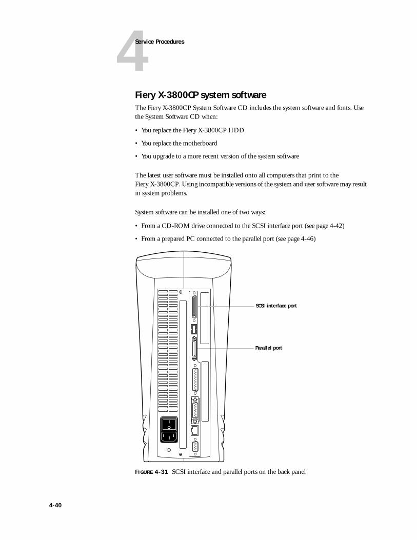
4Service Procedures
Fiery X-3800CP system softwareThe Fiery X-3800CP System Software CD includes the system software and fonts. Use the System Software CD when:
• You replace the Fiery X-3800CP HDD
• You replace the motherboard
• You upgrade to a more recent version of the system software
The latest user software must be installed onto all computers that print to theFiery X-3800CP. Using incompatible versions of the system and user software may result in system problems.
System software can be installed one of two ways:
• From a CD-ROM drive connected to the SCSI interface port (see page 4-42)
• From a prepared PC connected to the parallel port (see page 4-46)
FIGURE 4-31 SCSI interface and parallel ports on the back panel
SCSI interface port
Parallel port
4-40
4Fiery X-3800CP system software
System software installation remindersKeep in mind the following when installing system software:
• Compatibility—The latest user software should be installed onto all computers that print to the Fiery X-3800CP. Using incompatible versions of the system and user software may result in system problems.
• Job Log—Formatting the HDD to install system software deletes the list of jobs in the Job Log and any jobs in the queues. The network administrator can use Fiery Spooler to save a current list of jobs (not the actual jobs) from the Job Log.
• Fonts—Formatting the HDD to install system software deletes all fonts installed on the Fiery X-3800CP HDD. Resident fonts are restored during system software installation. If any additional fonts were downloaded to the Fiery X-3800CP, the network administrator can reinstall the fonts using Fiery Downloader.
To determine which additional fonts were downloaded to the Fiery X-3800CP, print the font list before you format the HDD and again after you complete the system software installation. Any fonts not listed after installation will need to be reinstalled. See the User Guide for more information.
• Custom simulations––Custom simulations used with previous versions of the operating system will be deleted when you install system software. The custom simulations will need to be redone.
• Language—Screens for installing system software are always displayed in English even if the Fiery X-3800CP is configured for another language.
4-41
4Service Procedures
Installing system software using the SCSI interface portTo install system software using the SCSI port on the Fiery X-3800CP, you need:
• An external CD-ROM drive that is:
• Properly terminated
• Set to use a SCSI ID number other than 0 (zero) or 7
• A SCSI II (50-pin) to SCSI I (50-pin) SCSI interface cable to connect the CD-ROM drive to the Fiery X-3800CP
TO PREPARE FOR INSTALLATION USING THE SCSI INTERFACE PORT
1. Print the Configuration page from the Functions menu (if possible) to record the customer’s Setup Configuration.
Setup settings are reset to the default configuration when system software is installed.
2. Print the Font List from the Functions menu.
The Font List details what fonts are installed on the Fiery X-3800CP HDD. Along with the fonts that are provided on the System Software CD, the customer may have installed additional fonts that will be deleted when the HDD is formatted.
3. Verify that the CD-ROM drive and Fiery X-3800CP are powered off.
4. Connect the SCSI I connector of the SCSI interface cable to the CD-ROM drive.
5. Connect the SCSI II connector of the SCSI interface cable to the SCSI interface port on the back of the Fiery X-3800CP.
6. Power on the CD-ROM drive, push the eject button, and insert the Fiery X-3800CP System Software CD.
7. Make sure the CD-ROM drive is free of activity, power on the Fiery X-3800CP, and let it complete its Start-up diagnostics. As soon as you see the message, “For software update or setup, press any key,” press any button on the Control Panel.
NOTE: If you do not press a button within three seconds, the Fiery X-3800CP continues the startup process. If this occurs, reboot the Fiery X-3800CP and try again.
4-42
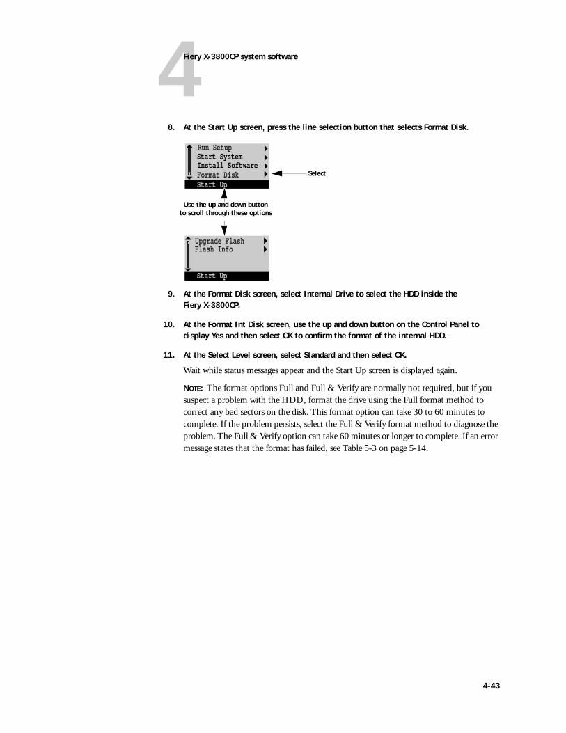
4Fiery X-3800CP system software
8. At the Start Up screen, press the line selection button that selects Format Disk.
9. At the Format Disk screen, select Internal Drive to select the HDD inside the Fiery X-3800CP.
10. At the Format Int Disk screen, use the up and down button on the Control Panel to display Yes and then select OK to confirm the format of the internal HDD.
11. At the Select Level screen, select Standard and then select OK.
Wait while status messages appear and the Start Up screen is displayed again.
NOTE: The format options Full and Full & Verify are normally not required, but if you suspect a problem with the HDD, format the drive using the Full format method to correct any bad sectors on the disk. This format option can take 30 to 60 minutes to complete. If the problem persists, select the Full & Verify format method to diagnose the problem. The Full & Verify option can take 60 minutes or longer to complete. If an error message states that the format has failed, see Table 5-3 on page 5-14.
Start SystemInstall SoftwareFormat Disk
Upgrade Flash
Run Setup
Start Up
Flash Info
Start Up
Select
Use the up and down button to scroll through these options
4-43
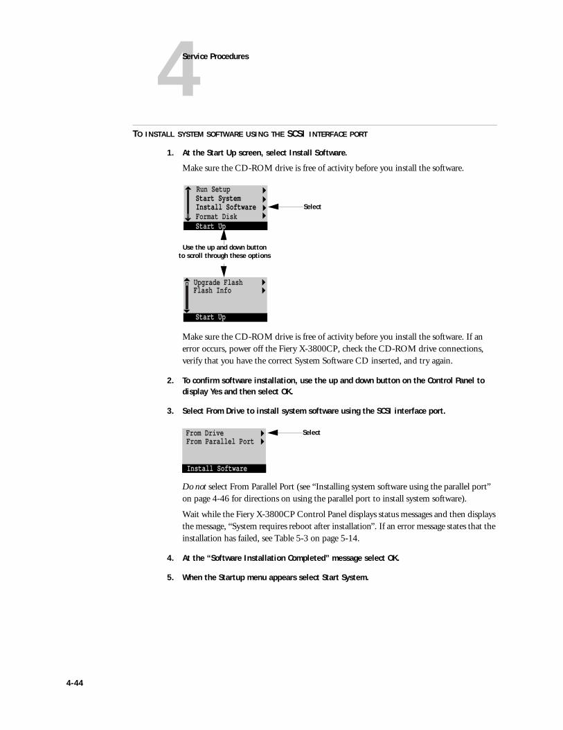
4Service Procedures
TO INSTALL SYSTEM SOFTWARE USING THE SCSI INTERFACE PORT
1. At the Start Up screen, select Install Software.
Make sure the CD-ROM drive is free of activity before you install the software.
Make sure the CD-ROM drive is free of activity before you install the software. If an error occurs, power off the Fiery X-3800CP, check the CD-ROM drive connections, verify that you have the correct System Software CD inserted, and try again.
2. To confirm software installation, use the up and down button on the Control Panel to display Yes and then select OK.
3. Select From Drive to install system software using the SCSI interface port.
Do not select From Parallel Port (see “Installing system software using the parallel port” on page 4-46 for directions on using the parallel port to install system software).
Wait while the Fiery X-3800CP Control Panel displays status messages and then displays the message, “System requires reboot after installation”. If an error message states that the installation has failed, see Table 5-3 on page 5-14.
4. At the “Software Installation Completed” message select OK.
5. When the Startup menu appears select Start System.
Start SystemInstall SoftwareFormat Disk
Upgrade Flash
Run Setup
Start Up
Flash Info
Start Up
Use the up and down button to scroll through these options
Select
From DriveFrom Parallel Port
Install Software
Select
4-44
4Fiery X-3800CP system software
6. At the message, “System requires reboot after installation”, select OK. Wait as the Fiery X-3800CP reboots, then watch for the Language Setup screen.
NOTE: Do not press any buttons on the Control Panel when the message appears: “For software update or setup, press any key.”
7. At the Language Setup screen, display the name of the language you want displayed on the Control Panel and select OK.
Use the up and down button on the Control Panel to cycle through the languages available. If you select a language different from the default, the system reboots and then presents screen text in the language you selected.
8. At the Setup screen, reenter the customer’s settings from the Configuration page that you printed earlier.
The Fiery X-3800CP will reboot once the settings have been entered. Bypass settings not included on the Configuration page if it is more appropriate for the network administrator to set them. See the Administrator Guide for more information.
9. After the Fiery X-3800CP reaches the Idle screen and the CD-ROM drive is free of activity, press the eject button and remove the System Software CD.
10. Power off the Fiery X-3800CP and the CD-ROM drive and remove the SCSI cable from the back of the Fiery X-3800CP and the CD-ROM drive.
4-45
4Service Procedures
Installing system software using the parallel portTo install system software using the parallel port on the Fiery X-3800CP, you need:
• A PC with Windows 95 or 98 that meets these minimum requirements:
• CD-ROM drive (built-in or attached)
• At least 200MB of disk space free
• Support for ECP mode on the parallel port (Compatibility mode will work, but the installation will take much longer.)
• The parallel cable included in the Fiery X-3800CP shipping box
The PC will need to be configured so the parallel port mode in the BIOS is set to ECP. When you access the PC BIOS, you may discover that ECP is the default mode, or you may discover that ECP mode is not supported at all. If ECP is not supported, you can use a different PC, or opt for a much slower installation using Compatibility Mode.
In addition to accessing the BIOS, setting up the PC also requires certain port and printer settings in Windows. Before you begin installing system software, follow the procedures for setting up the PC.
4-46
4Fiery X-3800CP system software
TO SET UP THE PC
1. Access the PC BIOS and make sure that Parallel Port Mode is set to ECP.
Power on the PC and immediately press the key indicated on your monitor for entering the BIOS (or a likely key if it is not indicated). Pressing a likely key repeatedly (ESC, DEL, F1, or a combination) may interrupt the starting of Windows and access the BIOS or give you directions for accessing the BIOS.
Once in the BIOS, you may have to scroll through several screens to reach the settings for the parallel port. After setting the Parallel Port Mode to ECP, save your changes and exit the BIOS.
2. Install the PostScript printer driver for the Fiery X-3800CP from the User Software CD in the Windows 95 or 98 subdirectory.
This driver supports IEEE 1284-C throughput over an ECP parallel port and allows you to configure all port and spool settings required for a successful installation. You may skip this step if a comparable printer driver is already installed on the PC. See Getting Started for directions on installing printer drivers.
3. In Windows, click the Start button, select Settings, and click Printers.
4. Click the icon for the printer and choose Properties from the File menu.
5. Click the Details tab and make sure the box “Print to the following port:” reads exactly as follows: LPT 1: (ECP Printer Port).
If this box reads LPT 1: (Printer Port) instead of LPT 1: (ECP Printer Port), the LPT1 port settings in the BIOS for ECP mode have not been configured. Compatibility mode will work but the installation will take much longer. Reboot the PC to reenter BIOS and set the Parallel Port Mode to ECP.
6. Click Spool Settings and select “Spool print jobs so program finishes printing faster,” “Start printing after last page is spooled,” and “Disable bi-directional support for this printer”. Then click Apply and click OK.
“Start printing after last page is spooled” takes longer but assures no disruption from a parallel port timeout.
Disabling Windows support for the bi-directional parallel port helps the system software installation to succeed. Using the PostScript printer driver included in the Windows 95or 98 subdirectory of the Fiery X-3800CP User Software CD ensures that this option is not grayed out.
7. Click Port Settings and ensure that “Spool MS-DOS print jobs” and “Check port state before printing” are checked. Click OK.
8. Click Apply, then OK to activate the settings and exit from the Printer Properties screen.
The PC is properly configured. Now prepare for the installation.
4-47
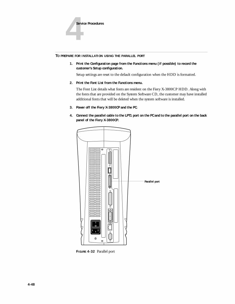
4Service Procedures
TO PREPARE FOR INSTALLATION USING THE PARALLEL PORT
1. Print the Configuration page from the Functions menu (if possible) to record the customer’s Setup configuration.
Setup settings are reset to the default configuration when the HDD is formatted.
2. Print the Font List from the Functions menu.
The Font List details what fonts are resident on the Fiery X-3800CP HDD. Along with the fonts that are provided on the System Software CD, the customer may have installed additional fonts that will be deleted when the system software is installed.
3. Power off the Fiery X-3800CP and the PC.
4. Connect the parallel cable to the LPT1 port on the PC and to the parallel port on the back panel of the Fiery X-3800CP.
FIGURE 4-32 Parallel port
Parallel port
4-48
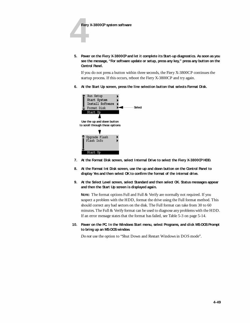
4Fiery X-3800CP system software
5. Power on the Fiery X-3800CP and let it complete its Start-up diagnostics. As soon as you see the message, “For software update or setup, press any key,” press any button on the Control Panel.
If you do not press a button within three seconds, the Fiery X-3800CP continues the startup process. If this occurs, reboot the Fiery X-3800CP and try again.
6. At the Start Up screen, press the line selection button that selects Format Disk.
7. At the Format Disk screen, select Internal Drive to select the Fiery X-3800CP HDD.
8. At the Format Int Disk screen, use the up and down button on the Control Panel to display Yes and then select OK to confirm the format of the internal drive.
9. At the Select Level screen, select Standard and then select OK. Status messages appear and then the Start Up screen is displayed again.
NOTE: The format options Full and Full & Verify are normally not required. If you suspect a problem with the HDD, format the drive using the Full format method. This should correct any bad sectors on the disk. The Full format can take from 30 to 60 minutes. The Full & Verify format can be used to diagnose any problems with the HDD. If an error message states that the format has failed, see Table 5-3 on page 5-14.
10. Power on the PC. In the Windows Start menu, select Programs, and click MS-DOS Prompt to bring up an MS-DOS window.
Do not use the option to “Shut Down and Restart Windows in DOS mode”.
Start SystemInstall SoftwareFormat Disk
Upgrade Flash
Run Setup
Start Up
Flash Info
Start Up
Use the up and down button to scroll through these options
Select
4-49
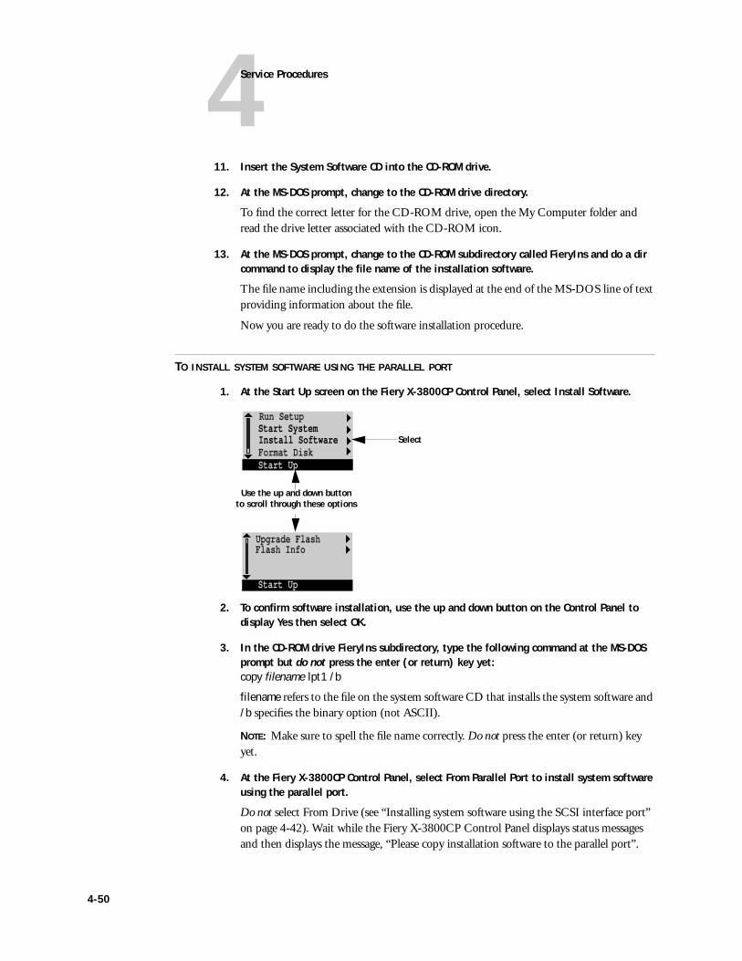
4Service Procedures
11. Insert the System Software CD into the CD-ROM drive.
12. At the MS-DOS prompt, change to the CD-ROM drive directory.
To find the correct letter for the CD-ROM drive, open the My Computer folder and read the drive letter associated with the CD-ROM icon.
13. At the MS-DOS prompt, change to the CD-ROM subdirectory called FieryIns and do a dir command to display the file name of the installation software.
The file name including the extension is displayed at the end of the MS-DOS line of text providing information about the file.
Now you are ready to do the software installation procedure.
TO INSTALL SYSTEM SOFTWARE USING THE PARALLEL PORT
1. At the Start Up screen on the Fiery X-3800CP Control Panel, select Install Software.
2. To confirm software installation, use the up and down button on the Control Panel to display Yes then select OK.
3. In the CD-ROM drive FieryIns subdirectory, type the following command at the MS-DOS prompt but do not press the enter (or return) key yet:copy filename lpt1 /b
filename refers to the file on the system software CD that installs the system software and /b specifies the binary option (not ASCII).
NOTE: Make sure to spell the file name correctly. Do not press the enter (or return) key yet.
4. At the Fiery X-3800CP Control Panel, select From Parallel Port to install system software using the parallel port.
Do not select From Drive (see “Installing system software using the SCSI interface port” on page 4-42). Wait while the Fiery X-3800CP Control Panel displays status messages and then displays the message, “Please copy installation software to the parallel port”.
Start SystemInstall SoftwareFormat Disk
Upgrade Flash
Run Setup
Start Up
Flash Info
Start Up
Use the up and down button to scroll through these options
Select
4-50
4Fiery X-3800CP system software
5. At the message, “Please copy installation software to the parallel port,” press the enter (or return) key on the PC.
Wait while the Fiery X-3800CP Control Panel displays status messages that the Fiery X-3800CP is receiving the file, clearing the port, and unpacking the file.
NOTE: If you get a “Parallel port timeout” message, press the enter key again to send the file to the Fiery X-3800CP.
6. At the “Software Installation Completed” message select OK.
7. When the Startup menu appears select Start System.
8. When “System requires reboot after installation” appears, select OK and then wait as the Fiery X-3800CP reboots.
Do not press any buttons on the Control Panel when the “For software update or setup, press any key” message appears.
9. At the Language Setup screen, display the name of the language you want displayed on the Control Panel and select OK.
Use the up and down button on the Control Panel to cycle through the languages available. If you select a language different from the default, the system reboots and then presents screen text in the language you selected.
10. At the Setup screen, reenter the customer’s settings from the Configuration page that you printed earlier.
Bypass settings not included on the Configuration page if it is more appropriate for the network administrator to set them. See the Administrator Guide for more information.
11. When the Fiery X-3800CP reaches the Idle screen, remove the System Software CD from the PC.
12. Power off the Fiery X-3800CP and the PC and remove the parallel port cable from the back of the Fiery X-3800CP and the PC
If the PC was connected to the Fiery X-3800CP before you installed system software, do not disconnect it.
4-51

5The troubleshooting process
This chapter identifies the source of common problems that may occur with the Fiery X-3800CP and suggests ways of correcting them.
NOTE: The information in this chapter will aid you in diagnosing problems that customers may experience. Some actions may suggest that you perform procedures not supported on the Fiery X-3800CP.
The troubleshooting processThe troubleshooting process is designed to eliminate the most obvious causes of failure before progressing to more complex solutions. “Where problems occur” on page 5-3 gives an overview of the Fiery X-3800CP system and indicates areas most likely to require troubleshooting.
• Problems with initial installation
If the Fiery X-3800CP fails to complete its initial startup and doesn’t reach the Idle (ready to print) screen, the most likely cause is a loose cable or board connection. See “Accessing internal components” on page 4-3 for instructions on opening the Fiery X-3800CP, and “Checking internal connections” on page 4-9 for descriptions of Fiery X-3800CP parts and connections.
If a loose part or cable is not the cause of the problem, see “Checking the Fiery X-3800CP as a stand-alone unit” on page 5-9, and “Checking the entire Fiery X-3800CP system” on page 5-23.
• Try a phone check before you go to the customer site
“Before you go to the customer site” on page 5-4 suggests areas you should check out before making a service call to the customer site. With a phone call you can find out if the problem is a simple operating failure or a failure caused by a network or configuration change. You can ask the customer to check for loose cables on the back of the Fiery X-3800CP and loose connections at a power strip or outlet.
• Check for obvious causes of problems
“Preliminary on-site checkout” on page 5-6 takes you through the initial checkout you should make when you arrive at the customer site. You should check the Fiery X-3800CP internally and externally for the most common problems such as loose cables, connectors, and boards.
Chapter 5: Troubleshooting Procedures
5-1
5Troubleshooting Procedures
• Check the Fiery X-3800CP as a stand-alone unit
“Checking the Fiery X-3800CP as a stand-alone unit” on page 5-9 describes the checks you should perform on the Fiery X-3800CP if the initial checks fail to identify the cause of a problem. With the Fiery X-3800CP disconnected from the printer and the network, test the Fiery X-3800CP as a stand-alone unit.
This section describes possible startup errors and explains how to run and interpret Fiery X-3800CP diagnostics.
• Check the entire Fiery X-3800CP system
“Checking the printer interface” on page 5-23 explains how to print the Test Page from the Fiery X-3800CP. “Checking network connections” on page 5-25 includes guidelines for checking the network connections between the Fiery X-3800CP and the computers or workstation to which it is connected, and also provides information on several printing problems.
5-2
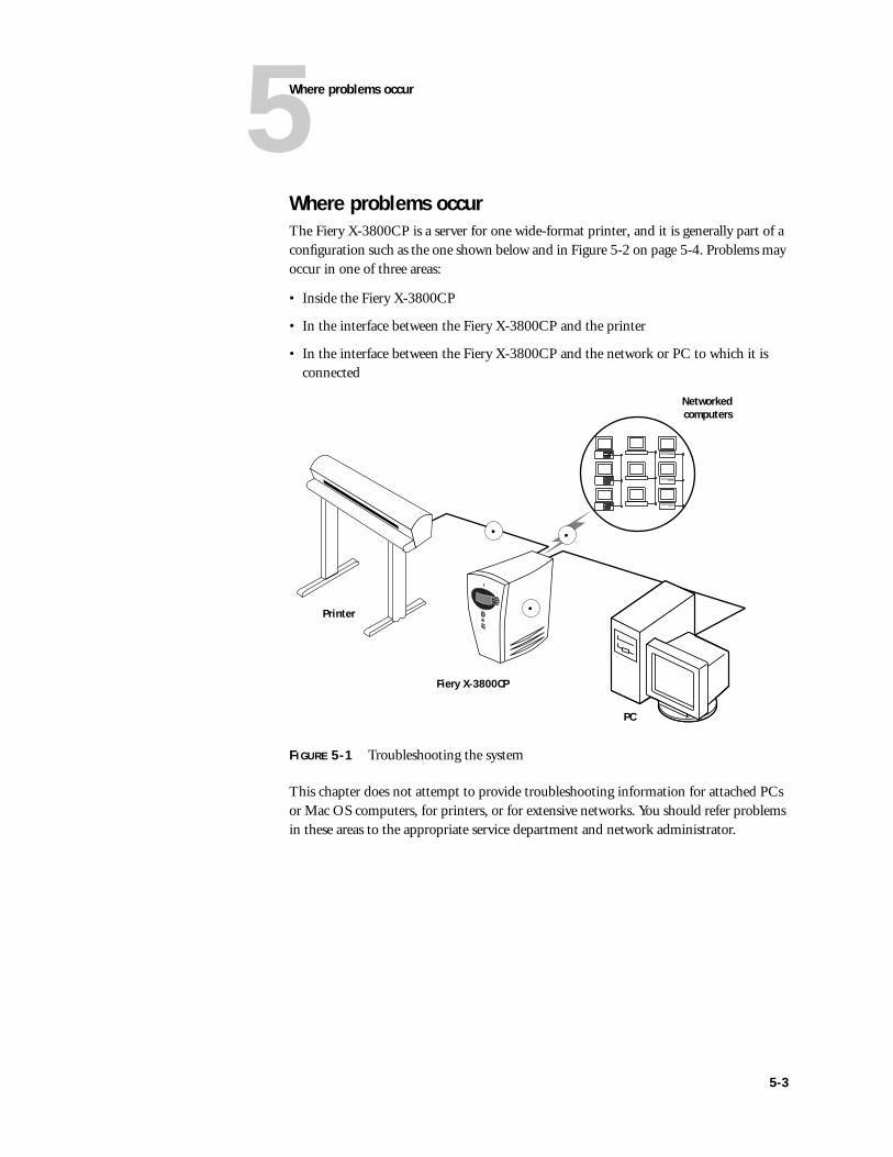
5Where problems occur
Where problems occurThe Fiery X-3800CP is a server for one wide-format printer, and it is generally part of a configuration such as the one shown below and in Figure 5-2 on page 5-4. Problems may occur in one of three areas:
• Inside the Fiery X-3800CP
• In the interface between the Fiery X-3800CP and the printer
• In the interface between the Fiery X-3800CP and the network or PC to which it is connected
FIGURE 5-1 Troubleshooting the system
This chapter does not attempt to provide troubleshooting information for attached PCs or Mac OS computers, for printers, or for extensive networks. You should refer problems in these areas to the appropriate service department and network administrator.
Printer
Fiery X-3800CP
PC
Networkedcomputers
•
•
•
5-3
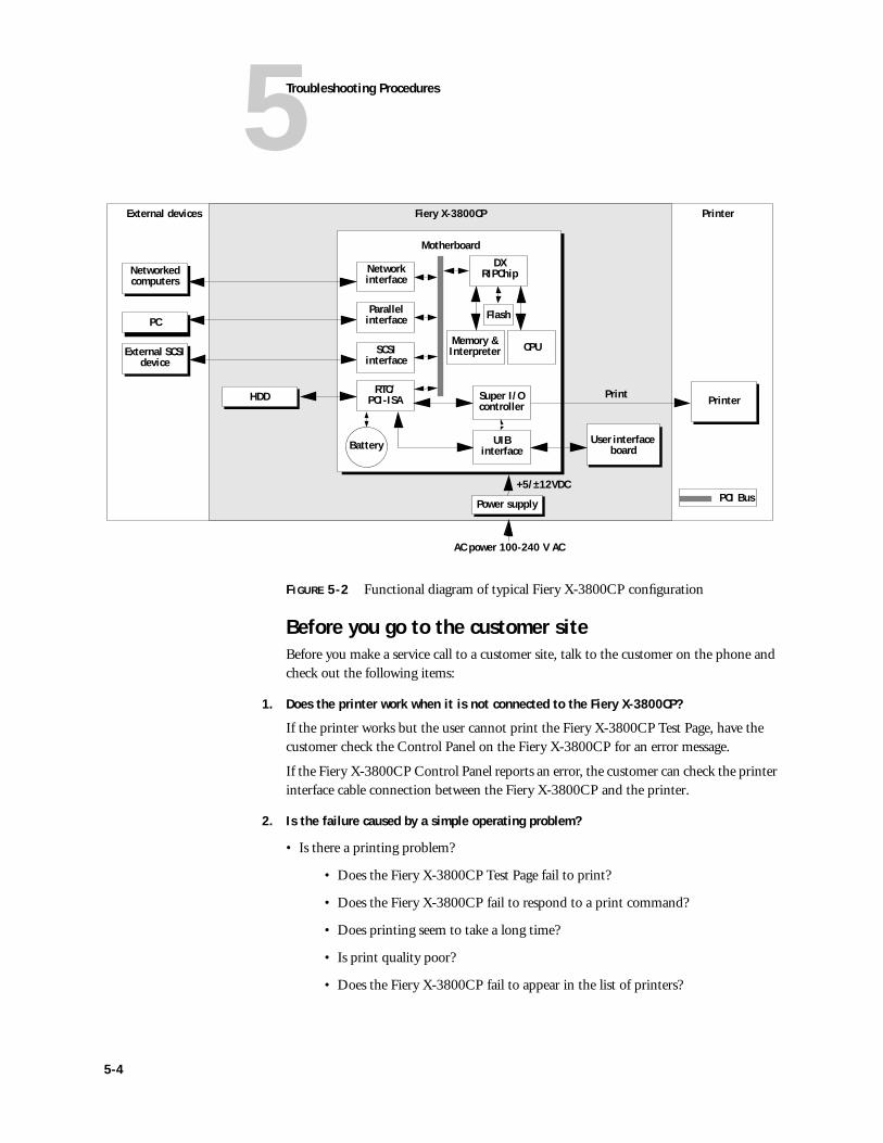
5Troubleshooting Procedures
FIGURE 5-2 Functional diagram of typical Fiery X-3800CP configuration
Before you go to the customer siteBefore you make a service call to a customer site, talk to the customer on the phone and check out the following items:
1. Does the printer work when it is not connected to the Fiery X-3800CP?
If the printer works but the user cannot print the Fiery X-3800CP Test Page, have the customer check the Control Panel on the Fiery X-3800CP for an error message.
If the Fiery X-3800CP Control Panel reports an error, the customer can check the printer interface cable connection between the Fiery X-3800CP and the printer.
2. Is the failure caused by a simple operating problem?
• Is there a printing problem?
• Does the Fiery X-3800CP Test Page fail to print?
• Does the Fiery X-3800CP fail to respond to a print command?
• Does printing seem to take a long time?
• Is print quality poor?
• Does the Fiery X-3800CP fail to appear in the list of printers?
Motherboard
Power supply
External devices PrinterFiery X-3800CP
+5/±12VDC
AC power 100-240 V AC
CPU
Network interface
User interface board
Memory &Interpreter
Printer
External SCSI device
DX RIPChip
Flash
Networked computers
PC
RTC/PCI-ISA
Parallel interface
SCSIinterface
Battery
HDD Super I/Ocontroller
UIBinterface
PCI Bus
5-4
5Before you go to the customer site
• Has the customer noted any error messages on the Fiery X-3800CP or the printer screen?
If the answer to any of these questions is yes, refer the customer to the User Guide. If the customer has followed the corrective actions in the User Guide and has failed to solve the problem, be prepared to make a service call. Keep a log of the failures and messages the customer has observed.
3. Has the customer made any network changes?
If so, request that the customer’s network administrator verify the Fiery X-3800CP network requirements. See “Checking network connections” on page 5-25.
4. Has the customer added or removed any equipment that might impact the operation of the Fiery X-3800CP?
If so, obtain a list of the modifications. This should direct you toward possible problem areas. For example, if the HDD has been replaced, system software may need to be reinstalled.
5. Is the user having printing problems with a particular image file?
If there are problems with files from particular applications, the user may be more successful using different print settings. See the User Guide for more information.
If your preliminary phone call fails to clear up the problem, proceed to the second phase, the preliminary on-site checkout.
5-5
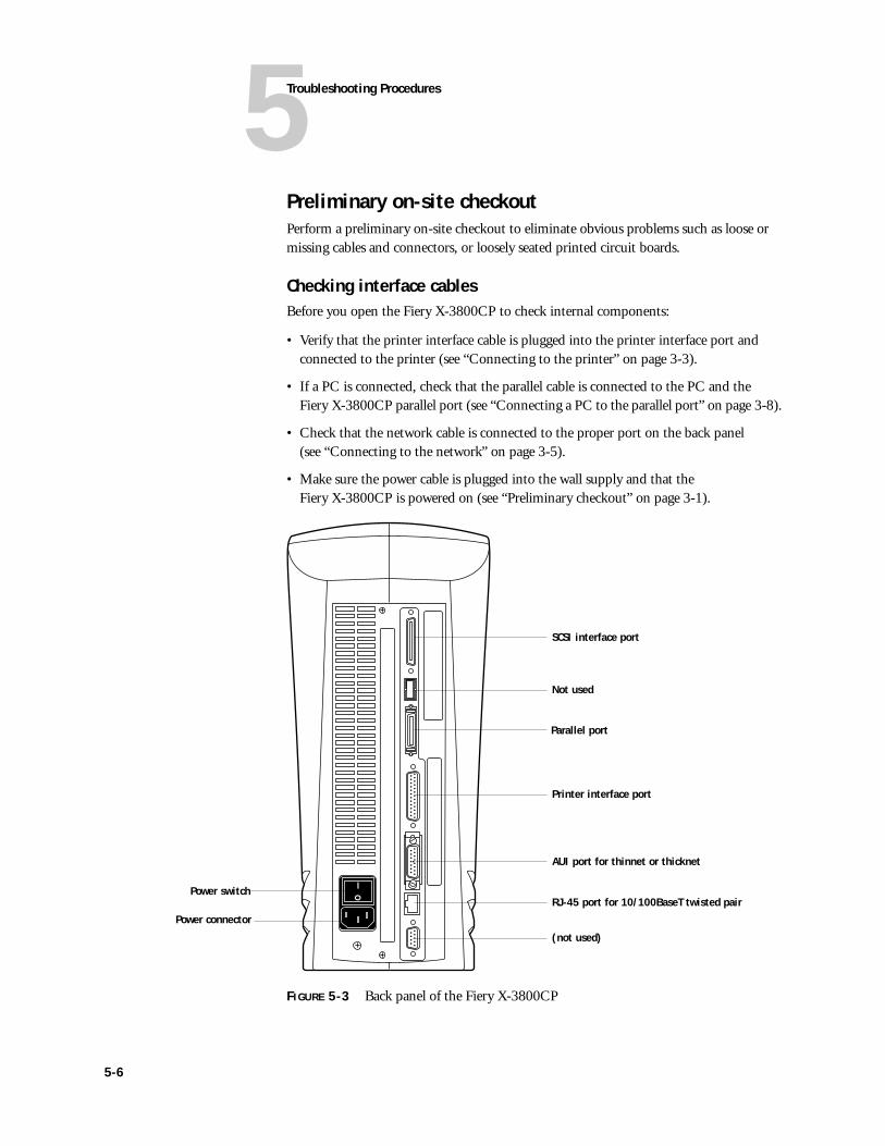
5Troubleshooting Procedures
Preliminary on-site checkoutPerform a preliminary on-site checkout to eliminate obvious problems such as loose or missing cables and connectors, or loosely seated printed circuit boards.
Checking interface cablesBefore you open the Fiery X-3800CP to check internal components:
• Verify that the printer interface cable is plugged into the printer interface port and connected to the printer (see “Connecting to the printer” on page 3-3).
• If a PC is connected, check that the parallel cable is connected to the PC and the Fiery X-3800CP parallel port (see “Connecting a PC to the parallel port” on page 3-8).
• Check that the network cable is connected to the proper port on the back panel (see “Connecting to the network” on page 3-5).
• Make sure the power cable is plugged into the wall supply and that the Fiery X-3800CP is powered on (see “Preliminary checkout” on page 3-1).
FIGURE 5-3 Back panel of the Fiery X-3800CP
SCSI interface port
Not used
Printer interface port
AUI port for thinnet or thicknet
RJ-45 port for 10/100BaseT twisted pair
(not used)
Parallel port
Power switch
Power connector
5-6
5Preliminary on-site checkout
Checking internal componentsTo check the internal components you must open the Fiery X-3800CP. For an overview of internal components, see Figure 5-4 on page 5-8. Check the following components:
• Circuit boards (UIB, video interface board assembly, and motherboard)
• Fans (exhaust fan and CPU fan)
• Power switch and power supply
• Hard disk drive
Before you open the Fiery X-3800CP, be aware of the safety precautions you should take when handling the Fiery X-3800CP, and use ESD precautions when handling printed circuit boards and electronic components. To review the safety precautions, see “Precautions” on page xiii.
Use the guidelines in Chapter 4 when disassembling, checking, and reassembling the Fiery X-3800CP.
TO CHECK INTERNAL COMPONENTS
1. Power off and open the Fiery X-3800CP (see “Accessing internal components” on page 4-3).
2. Before you touch any components inside the Fiery X-3800CP chassis, attach an ESD grounding strap to your wrist. Discharge any static electricity on your body by touching the metal back panel of the Fiery X-3800CP.
3. Inspect the inside of the chassis.
• Check the connections between an option board (if present) and the motherboard. If a board is loose, reseat it securely in its connector.
• Look for cables that are obviously loose. Reseat each cable firmly. See Figure 4-8 on page 4-10 for an overview of the cables in the Fiery X-3800CP. Make sure that the power supply cable, AC power cable and ground cables are properly connected to the power supply.
• Make sure each connector is properly aligned with its mating connector. If any pins are offset from each other, the component affected will not function properly.
• Check DIMMs to make sure they are properly seated in their slots.
4. Reassemble the Fiery X-3800CP and verify functionality (see “Restoring functionality after service” on page 4-12).
5-7
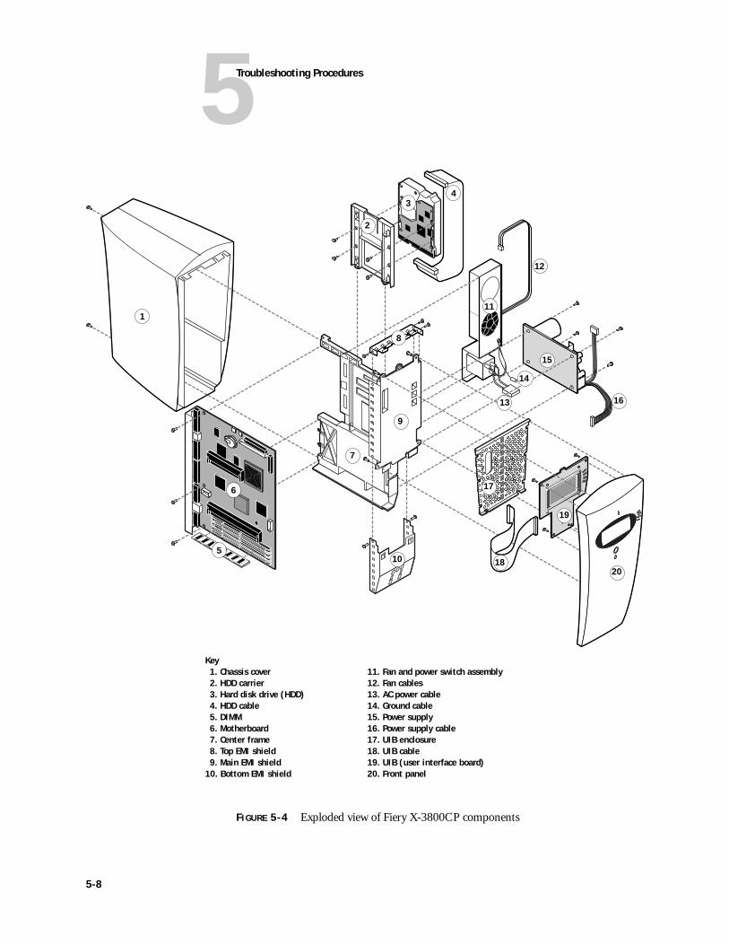
5Troubleshooting Procedures
FIGURE 5-4 Exploded view of Fiery X-3800CP components
Key1. Chassis cover 11. Fan and power switch assembly2. HDD carrier 12. Fan cables3. Hard disk drive (HDD) 13. AC power cable4. HDD cable 14. Ground cable5. DIMM 15. Power supply6. Motherboard 16. Power supply cable7. Center frame 17. UIB enclosure8. Top EMI shield 18. UIB cable9. Main EMI shield 19. UIB (user interface board)
10. Bottom EMI shield 20. Front panel
1
34
5
6
8
2
7
99
10
11
12
13
14
15
16
17
18
19
20
5-8
5Checking the Fiery X-3800CP as a stand-alone unit
Checking the Fiery X-3800CP as a stand-alone unitTo test the Fiery X-3800CP as a stand-alone unit:
• Disconnect the Fiery X-3800CP from the printer and from the network
• Check for possible startup problems
• Check Setup
• Run diagnostics
TO ISOLATE THE FIERY X-3800CP
1. Power off the Fiery X-3800CP and disconnect the following cables from the Fiery X-3800CP:
• Printer interface cable
• Network cable
• Parallel cable (if a PC is connected to the parallel port)
2. Make sure the power cable to the Fiery X-3800CP is still in place.
3. Power on the Fiery X-3800CP and allow the startup diagnostics to run.
Errors during Start-up diagnosticsWhen you power on the Fiery X-3800CP or reboot, the system goes through a series of diagnostic tests that check the motherboard. While the diagnostic tests are running, the name of the test and a progress bar are displayed on the Control Panel.
If an error occurs during Start-up diagnostics, the red activity light on the Fiery X-3800CP Control Panel will flash. After the diagnostics have finished, the red activity light will remain on and the Test Failed screen appears. Select the line selection button to the right of Details in the Test Failed screen for more information about the test that failed.
5-9
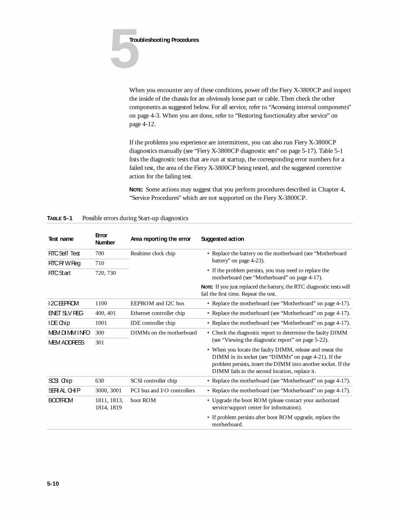
5Troubleshooting Procedures
When you encounter any of these conditions, power off the Fiery X-3800CP and inspect the inside of the chassis for an obviously loose part or cable. Then check the other components as suggested below. For all service, refer to “Accessing internal components” on page 4-3. When you are done, refer to “Restoring functionality after service” on page 4-12.
If the problems you experience are intermittent, you can also run Fiery X-3800CP diagnostics manually (see “Fiery X-3800CP diagnostic sets” on page 5-17). Table 5-1 lists the diagnostic tests that are run at startup, the corresponding error numbers for a failed test, the area of the Fiery X-3800CP being tested, and the suggested corrective action for the failing test.
NOTE: Some actions may suggest that you perform procedures described in Chapter 4, “Service Procedures” which are not supported on the Fiery X-3800CP.
TABLE 5-1 Possible errors during Start-up diagnostics
Test name ErrorNumber Area reporting the error Suggested action
RTC Self Test 700 Realtime clock chip • Replace the battery on the motherboard (see “Motherboard battery” on page 4-23).
• If the problem persists, you may need to replace the motherboard (see “Motherboard” on page 4-17).
NOTE: If you just replaced the battery, the RTC diagnostic tests will fail the first time. Repeat the test.
RTC R/W Reg 710
RTC Start 720, 730
I2C EEPROM 1100 EEPROM and I2C bus • Replace the motherboard (see “Motherboard” on page 4-17).
ENET SLV REG 400, 401 Ethernet controller chip • Replace the motherboard (see “Motherboard” on page 4-17).
IDE Chip 1001 IDE controller chip • Replace the motherboard (see “Motherboard” on page 4-17).
MEM DIMM INFO 300 DIMMs on the motherboard • Check the diagnostic report to determine the faulty DIMM (see “Viewing the diagnostic report” on page 5-22).
• When you locate the faulty DIMM, release and reseat the DIMM in its socket (see “DIMMs” on page 4-21). If the problem persists, insert the DIMM into another socket. If the DIMM fails in the second location, replace it.
MEM ADDRESS 301
SCSI Chip 630 SCSI controller chip • Replace the motherboard (see “Motherboard” on page 4-17).
SERIAL CHIP 3000, 3001 PCI bus and I/O controllers • Replace the motherboard (see “Motherboard” on page 4-17).
BOOTROM 1811, 1813, 1814, 1819
boot ROM • Upgrade the boot ROM (please contact your authorized service/support center for information).
• If problem persists after boot ROM upgrade, replace the motherboard.
5-10
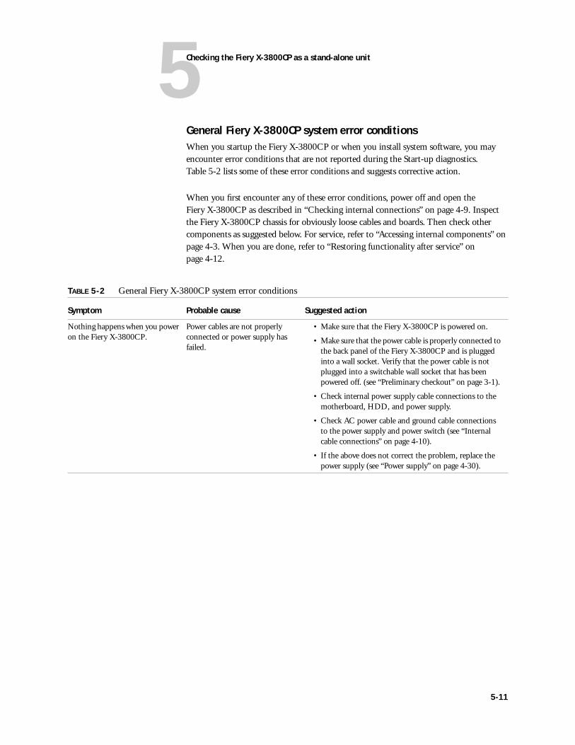
5Checking the Fiery X-3800CP as a stand-alone unit
General Fiery X-3800CP system error conditionsWhen you startup the Fiery X-3800CP or when you install system software, you may encounter error conditions that are not reported during the Start-up diagnostics. Table 5-2 lists some of these error conditions and suggests corrective action.
When you first encounter any of these error conditions, power off and open the Fiery X-3800CP as described in “Checking internal connections” on page 4-9. Inspect the Fiery X-3800CP chassis for obviously loose cables and boards. Then check other components as suggested below. For service, refer to “Accessing internal components” on page 4-3. When you are done, refer to “Restoring functionality after service” on page 4-12.
TABLE 5-2 General Fiery X-3800CP system error conditions
Symptom Probable cause Suggested action
Nothing happens when you power on the Fiery X-3800CP.
Power cables are not properly connected or power supply has failed.
• Make sure that the Fiery X-3800CP is powered on.
• Make sure that the power cable is properly connected to the back panel of the Fiery X-3800CP and is plugged into a wall socket. Verify that the power cable is not plugged into a switchable wall socket that has been powered off. (see “Preliminary checkout” on page 3-1).
• Check internal power supply cable connections to the motherboard, HDD, and power supply.
• Check AC power cable and ground cable connections to the power supply and power switch (see “Internal cable connections” on page 4-10).
• If the above does not correct the problem, replace the power supply (see “Power supply” on page 4-30).
5-11
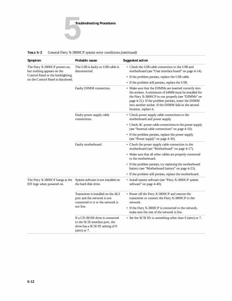
5Troubleshooting Procedures
The Fiery X-3800CP powers on, but nothing appears on the Control Panel or the backlighting on the Control Panel is discolored.
The UIB is faulty or UIB cable is disconnected.
• Check the UIB cable connection to the UIB and motherboard (see “User interface board” on page 4-14).
• If the problem persists, replace the UIB cable.
• If the problem still persists, replace the UIB.
Faulty DIMM connection. • Make sure that the DIMMs are inserted correctly into the sockets. A minimum of 64MB must be installed for the Fiery X-3800CP to run properly (see “DIMMs” on page 4-21). If the problem persists, insert the DIMM into another socket. If the DIMM fails in the second location, replace it.
Faulty power supply cable connections.
• Check power supply cable connections to the motherboard and power supply.
• Check AC power cable connections to the power supply (see “Internal cable connections” on page 4-10).
• If the problem persists, replace the power supply (see “Power supply” on page 4-30).
Faulty motherboard. • Check the power supply cable connection to the motherboard (see “Motherboard” on page 4-17).
• Make sure that all other cables are properly connected to the motherboard.
• If the problem persists, try replacing the motherboard battery (see “Motherboard battery” on page 4-23).
• If the problem still persists, replace the motherboard.
The Fiery X-3800CP hangs at the EFI logo when powered on.
System software is not installed on the hard disk drive.
• Install system software (see “Fiery X-3800CP system software” on page 4-40).
Transceiver is installed on the AUI port and the network is not connected to it or the network is not live.
• Power off the Fiery X-3800CP and remove the transceiver or connect the Fiery X-3800CP to the network.
• If the Fiery X-3800CP is connected to the network, make sure the rest of the network is live.
If a CD-ROM drive is connected to the SCSI interface port, the drive has a SCSI ID setting of 0 (zero) or 7.
• Set the SCSI ID to something other than 0 (zero) or 7.
TABLE 5-2 General Fiery X-3800CP system error conditions (continued)
Symptom Probable cause Suggested action
5-12
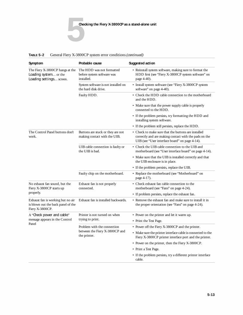
5Checking the Fiery X-3800CP as a stand-alone unit
The Fiery X-3800CP hangs at the Loading system... or the Loading settings... screen.
The HDD was not formatted before system software was installed.
• Reinstall system software, making sure to format the HDD first (see “Fiery X-3800CP system software” on page 4-40).
System software is not installed on the hard disk drive.
• Install system software (see “Fiery X-3800CP system software” on page 4-40).
Faulty HDD. • Check the HDD cable connection to the motherboard and the HDD.
• Make sure that the power supply cable is properly connected to the HDD.
• If the problem persists, try formatting the HDD and installing system software.
• If the problem still persists, replace the HDD.
The Control Panel buttons don’t work.
Buttons are stuck or they are not making contact with the UIB.
• Check to make sure that the buttons are installed correctly and are making contact with the pads on the UIB (see “User interface board” on page 4-14).
UIB cable connection is faulty or the UIB is bad.
• Check the UIB cable connection to the UIB and motherboard (see “User interface board” on page 4-14).
• Make sure that the UIB is installed correctly and that the UIB enclosure is in place.
• If the problem persists, replace the UIB.
Faulty chip on the motherboard. • Replace the motherboard (see “Motherboard” on page 4-17).
No exhaust fan sound, but theFiery X-3800CP starts up properly.
Exhaust fan is not properly connected.
• Check exhaust fan cable connection to the motherboard (see “Fans” on page 4-24).
• If problem persists, replace the exhaust fan.
Exhaust fan is working but no air is blown out the back panel of the Fiery X-3800CP.
Exhaust fan is installed backwards. • Remove the exhaust fan and make sure to install it in the proper orientation (see “Fans” on page 4-24).
A “Check power and cable” message appears in the Control Panel
Printer is not turned on when trying to print.
• Power on the printer and let it warm up.
• Print the Test Page.
Problem with the connection between the Fiery X-3800CP and the printer.
• Power off the Fiery X-3800CP and the printer.
• Make sure the printer interface cable is connected to the Fiery X-3800CP printer interface port and the printer.
• Power on the printer, then the Fiery X-3800CP.
• Print a Test Page.
• If the problem persists, try a different printer interface cable.
TABLE 5-2 General Fiery X-3800CP system error conditions (continued)
Symptom Probable cause Suggested action
5-13
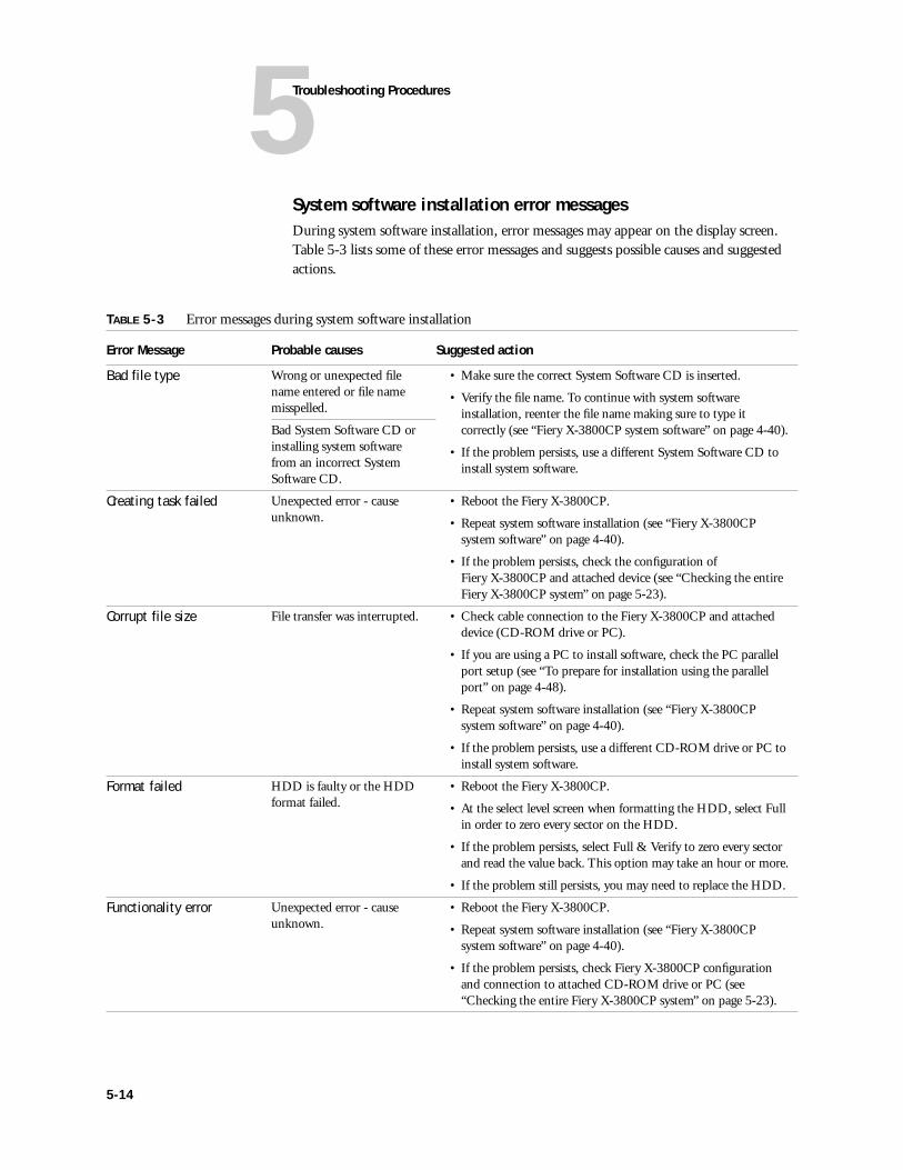
5Troubleshooting Procedures
System software installation error messagesDuring system software installation, error messages may appear on the display screen. Table 5-3 lists some of these error messages and suggests possible causes and suggested actions.
TABLE 5-3 Error messages during system software installation
Error Message Probable causes Suggested action
Bad file type Wrong or unexpected file name entered or file name misspelled.
• Make sure the correct System Software CD is inserted.
• Verify the file name. To continue with system software installation, reenter the file name making sure to type it correctly (see “Fiery X-3800CP system software” on page 4-40).
• If the problem persists, use a different System Software CD to install system software.
Bad System Software CD or installing system software from an incorrect System Software CD.
Creating task failed Unexpected error - cause unknown.
• Reboot the Fiery X-3800CP.
• Repeat system software installation (see “Fiery X-3800CP system software” on page 4-40).
• If the problem persists, check the configuration of Fiery X-3800CP and attached device (see “Checking the entire Fiery X-3800CP system” on page 5-23).
Corrupt file size File transfer was interrupted. • Check cable connection to the Fiery X-3800CP and attached device (CD-ROM drive or PC).
• If you are using a PC to install software, check the PC parallel port setup (see “To prepare for installation using the parallel port” on page 4-48).
• Repeat system software installation (see “Fiery X-3800CP system software” on page 4-40).
• If the problem persists, use a different CD-ROM drive or PC to install system software.
Format failed HDD is faulty or the HDD format failed.
• Reboot the Fiery X-3800CP.
• At the select level screen when formatting the HDD, select Full in order to zero every sector on the HDD.
• If the problem persists, select Full & Verify to zero every sector and read the value back. This option may take an hour or more.
• If the problem still persists, you may need to replace the HDD.
Functionality error Unexpected error - cause unknown.
• Reboot the Fiery X-3800CP.
• Repeat system software installation (see “Fiery X-3800CP system software” on page 4-40).
• If the problem persists, check Fiery X-3800CP configuration and connection to attached CD-ROM drive or PC (see “Checking the entire Fiery X-3800CP system” on page 5-23).
5-14
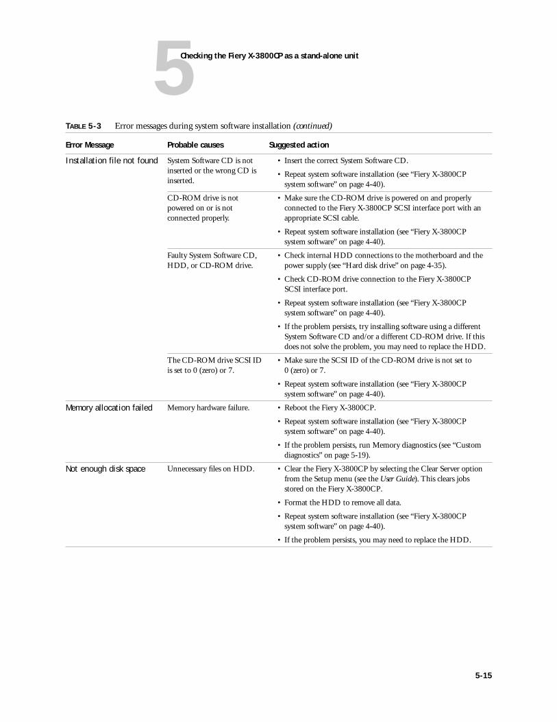
5Checking the Fiery X-3800CP as a stand-alone unit
Installation file not found System Software CD is not inserted or the wrong CD is inserted.
• Insert the correct System Software CD.
• Repeat system software installation (see “Fiery X-3800CP system software” on page 4-40).
CD-ROM drive is not powered on or is not connected properly.
• Make sure the CD-ROM drive is powered on and properly connected to the Fiery X-3800CP SCSI interface port with an appropriate SCSI cable.
• Repeat system software installation (see “Fiery X-3800CP system software” on page 4-40).
Faulty System Software CD, HDD, or CD-ROM drive.
• Check internal HDD connections to the motherboard and the power supply (see “Hard disk drive” on page 4-35).
• Check CD-ROM drive connection to the Fiery X-3800CP SCSI interface port.
• Repeat system software installation (see “Fiery X-3800CP system software” on page 4-40).
• If the problem persists, try installing software using a different System Software CD and/or a different CD-ROM drive. If this does not solve the problem, you may need to replace the HDD.
The CD-ROM drive SCSI ID is set to 0 (zero) or 7.
• Make sure the SCSI ID of the CD-ROM drive is not set to 0 (zero) or 7.
• Repeat system software installation (see “Fiery X-3800CP system software” on page 4-40).
Memory allocation failed Memory hardware failure. • Reboot the Fiery X-3800CP.
• Repeat system software installation (see “Fiery X-3800CP system software” on page 4-40).
• If the problem persists, run Memory diagnostics (see “Custom diagnostics” on page 5-19).
Not enough disk space Unnecessary files on HDD. • Clear the Fiery X-3800CP by selecting the Clear Server option from the Setup menu (see the User Guide). This clears jobs stored on the Fiery X-3800CP.
• Format the HDD to remove all data.
• Repeat system software installation (see “Fiery X-3800CP system software” on page 4-40).
• If the problem persists, you may need to replace the HDD.
TABLE 5-3 Error messages during system software installation (continued)
Error Message Probable causes Suggested action
5-15
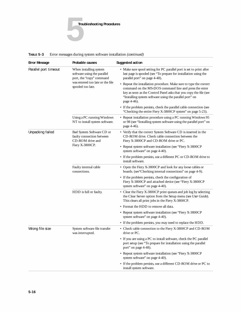
5Troubleshooting Procedures
Parallel port timeout When installing system software using the parallel port, the “copy” command was entered too late or the file spooled too late.
• Make sure spool setting for PC parallel port is set to print after last page is spooled (see “To prepare for installation using the parallel port” on page 4-48).
• Repeat the installation procedure. Make sure to type the correct command on the MS-DOS command line and press the enter key as soon as the Control Panel asks that you copy the file (see “Installing system software using the parallel port” on page 4-46).
• If the problem persists, check the parallel cable connection (see “Checking the entire Fiery X-3800CP system” on page 5-23).
Using a PC running Windows NT to install system software.
• Repeat installation procedure using a PC running Windows 95 or 98 (see “Installing system software using the parallel port” on page 4-46).
Unpacking failed Bad System Software CD or faulty connection between CD-ROM drive and Fiery X-3800CP.
• Verify that the correct System Software CD is inserted in the CD-ROM drive. Check cable connection between the Fiery X-3800CP and CD-ROM drive or PC.
• Repeat system software installation (see “Fiery X-3800CP system software” on page 4-40).
• If the problem persists, use a different PC or CD-ROM drive to install software.
Faulty internal cable connections.
• Open the Fiery X-3800CP and look for any loose cables or boards. (see“Checking internal connections” on page 4-9).
• If the problem persists, check the configuration of Fiery X-3800CP and attached device (see “Fiery X-3800CP system software” on page 4-40).
HDD is full or faulty. • Clear the Fiery X-3800CP print queues and job log by selecting the Clear Server option from the Setup menu (see User Guide). This clears all print jobs in the Fiery X-3800CP.
• Format the HDD to remove all data.
• Repeat system software installation (see “Fiery X-3800CP system software” on page 4-40).
• If the problem persists, you may need to replace the HDD.
Wrong file size System software file transfer was interrupted.
• Check cable connection to the Fiery X-3800CP and CD-ROM drive or PC.
• If you are using a PC to install software, check the PC parallel port setup (see “To prepare for installation using the parallel port” on page 4-48).
• Repeat system software installation (see “Fiery X-3800CP system software” on page 4-40).
• If the problem persists, use a different CD-ROM drive or PC to install system software.
TABLE 5-3 Error messages during system software installation (continued)
Error Message Probable causes Suggested action
5-16
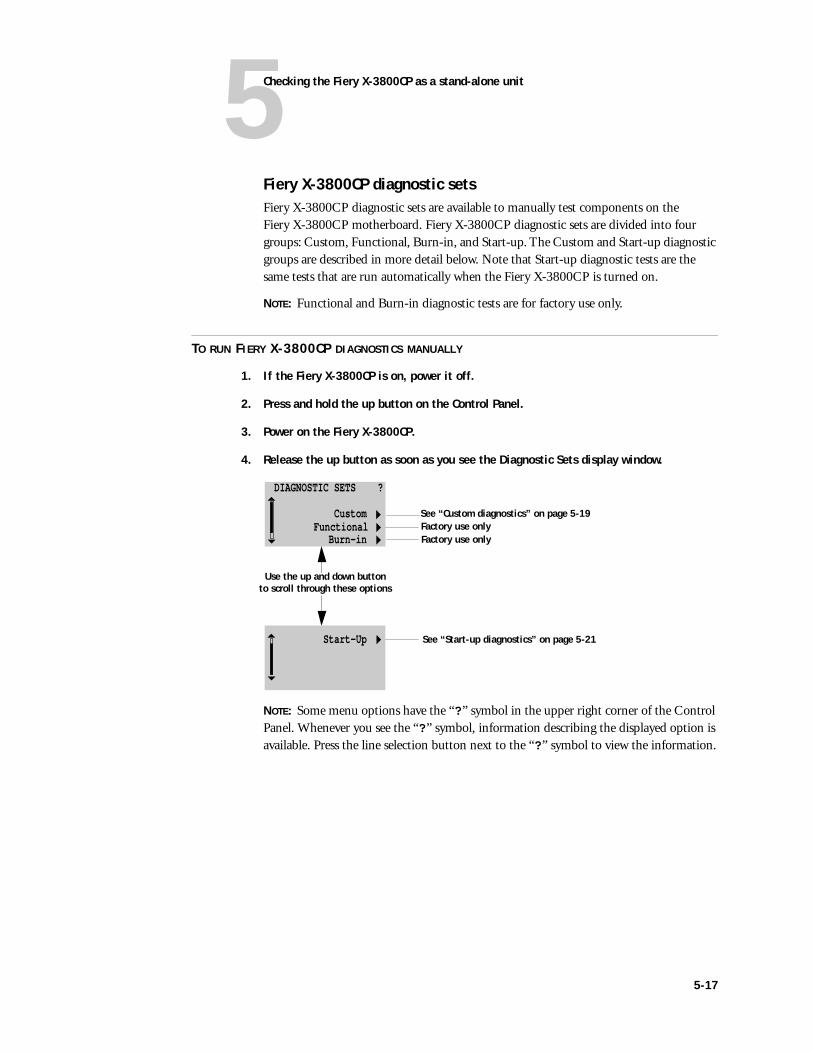
5Checking the Fiery X-3800CP as a stand-alone unit
Fiery X-3800CP diagnostic setsFiery X-3800CP diagnostic sets are available to manually test components on the Fiery X-3800CP motherboard. Fiery X-3800CP diagnostic sets are divided into four groups: Custom, Functional, Burn-in, and Start-up. The Custom and Start-up diagnostic groups are described in more detail below. Note that Start-up diagnostic tests are the same tests that are run automatically when the Fiery X-3800CP is turned on.
NOTE: Functional and Burn-in diagnostic tests are for factory use only.
TO RUN FIERY X-3800CP DIAGNOSTICS MANUALLY
1. If the Fiery X-3800CP is on, power it off.
2. Press and hold the up button on the Control Panel.
3. Power on the Fiery X-3800CP.
4. Release the up button as soon as you see the Diagnostic Sets display window.
NOTE: Some menu options have the “?” symbol in the upper right corner of the Control Panel. Whenever you see the “?” symbol, information describing the displayed option is available. Press the line selection button next to the “?” symbol to view the information.
DIAGNOSTIC SETS ?
Custom Burn-in
Functional
Start-Up
See “Custom diagnostics” on page 5-19Factory use onlyFactory use only
See “Start-up diagnostics” on page 5-21
Use the up and down buttonto scroll through these options
5-17
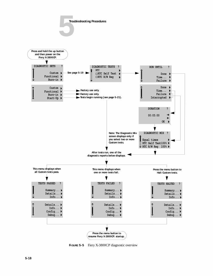
5Troubleshooting Procedures
FIGURE 5-5 Fiery X-3800CP diagnostic overview
DIAGNOSTIC SETS ?
Custom Burn-in
Functional
Start-Up
Custom Burn-in
Functional
Press the menu button to resume Fiery X-3800CP. startup.
TESTS FAILED ?
Summary... Details... Info...
Details... Info... Config... Debug...
DIAGNOSTIC TESTS ? RTC RTC Self Test RTC R/W Reg
DURATION ?
00:05:00
DIAGNOSTIC MIX ? Equal times RTC Self Test100% RTC R/W Reg 100%
OK
RUN UNTIL ?
Done Time... Failure Done Time... Failure Interrupted
Factory use only.Factory use only.Tests begin running (see page 5-21).
See page 5-19
TESTS HALTED ?
Summary... Details... Info...
Details... Info... Config... Debug...
TESTS PASSED ?
Summary... Details... Info...
Details... Info... Config... Debug...
After tests run, one of the diagnostic reports below displays.
Note: The Diagnostic Mix screen displays only if you select two or more Custom tests.
Press and hold the up button and then power on the
Fiery X-3800CP.
This menu displays when all Custom tests pass.
This menu displays when one or more tests fail.
Press the menu button to Halt Custom tests.
5-18
5Checking the Fiery X-3800CP as a stand-alone unit
Custom diagnostics
Custom diagnostics allow you to run individual tests in order to identify and isolate problems with the Fiery X-3800CP. When you select Custom from the list of Diagnostic Sets, a scrolling list of tests appears on the Control Panel.
Table 5-4, “Summary of Custom diagnostic tests,” on page 5-20 lists the Custom diagnostic tests that can be run at the customer site, the areas of the Fiery X-3800CP that are tested by the diagnostic tests, and suggests possible actions to take if the diagnostics fail.
NOTE: Custom diagnostic tests not listed in Table 5-4 on page 5-20 are intended for factory use and should not be run. These tests may fail or hang if performed in the field.
TO RUN CUSTOM DIAGNOSTICS
1. At the Diagnostic Sets screen, press the line selection button next to Custom (see “Fiery X-3800CP diagnostic sets” on page 5-17).
2. Select the tests that you want to run. Use the up and down button to scroll through the list.
To select a particular test, press the line selection button next to the test you want to run. If you decide you don’t want to run a test that is already selected, press the corresponding line selection button again. A filled-in box next to the test name indicates that the test has been selected; a hollow box means that the test is not selected.
3. Press the menu button when you are finished selecting the tests you want to run.
4. At the next screen, RUN UNTIL, select how long you want to run the tests. The following list of options is displayed:
Done The selected test runs through once. When you select this option the test starts running immediately
Time... Test runs for a specified amount of time. The length of time is set on the next screen in the Duration menu and is entered in the form HH:MM:SS (hours, minutes, and seconds). Use the up and down button to change the time and the line selection button to advance to the next field. After you set the time, select OK.
Failure The selected test repeats until a failure is detected.
Interrupted The selected test runs until you press the menu button on the Control Panel.
5-19
5Troubleshooting Procedures
5. At the DIAGNOSTIC MIX screen (only appears if you selected more than one test and you selected Time..., Failure, or Interrupted for the RUN UNTIL option), select the percentage of repetition for each test and then press the menu button. If you select the Equal Times option the tests begin running immediately.
Use the line selection buttons next to each test to change the percentage of repetition for each test (percentages are available in increments of ten). To scroll through the list, use the up and down button.
NOTE: Do not power off the Fiery X-3800CP while tests are running unless it appears that the system is not responding. If you have selected an incorrect test, wait until the test has completed or press the menu button to halt the test.
6. If any of the tests fail, check the Details option on the diagnostic report for more information about the failing test (see “Viewing the diagnostic report” on page 5-22).
Power off the Fiery X-3800CP, then perform the recommended service for the failed test or replace the failed component. See Table 5-4 for suggested actions.
7. Once the “Tests Passed” message appears on the Control Panel to indicate that all tests passed, press the menu button. When asked if you want to exit the custom tests, press the line selection button next to “Yes.” The Fiery X-3800CP will proceed with startup.
TABLE 5-4 Summary of Custom diagnostic tests
Group Test name Area tested Suggested action
IDE IDE HDD IDE Controller chip on motherboard, HDD cable, and HDD
• Check Fiery X-3800CP internal connections (see “Checking internal connections” on page 4-9).
• Replace the HDD cable if it looks damaged (see “Hard disk drive” on page 4-35).
• If the problem persists, you may need to replace the HDD and/or the motherboard.
Memory MEM GND BOUNCE DIMMs on motherboard • Check the diagnostic report to determine the faulty DIMM (see “Viewing the diagnostic report” on page 5-22).
• Check DIMMs to make sure they are seated properly.
• If the problem persists, replace the faulty DIMM indicated in the diagnostic report.
NOTE: Custom diagnostic tests not listed are for factory use and should not be run at the customer site.
5-20
5Checking the Fiery X-3800CP as a stand-alone unit
Start-up diagnostics
Start-up diagnostics include the set of Fiery X-3800CP tests listed in Table 5-1 on page 5-10. These tests are the same tests that are run automatically when you turn on the Fiery X-3800CP or reboot the system. The Start-up diagnostics focus on testing components on the Fiery X-3800CP motherboard.
TO RUN START-UP DIAGNOSTICS
1. At the Diagnostic Sets screen use the down button to scroll through the menu. Press the line selection button next to Start-up (see “Fiery X-3800CP diagnostic sets” on page 5-17). The tests begin running immediately.
2. If any of the tests fail, check the Details option in the diagnostic report menu for more information about the failing test (see “Viewing the diagnostic report” on page 5-22).
3. Power off the Fiery X-3800CP, and perform the recommended service for the failed test or replace the failed component.
4. After restarting the Fiery X-3800CP, if the Start-up diagnostics all pass the Fiery X-3800CP will automatically continue with the standard startup process (see “Errors during Start-up diagnostics” on page 5-9 for a list of tests).
5-21
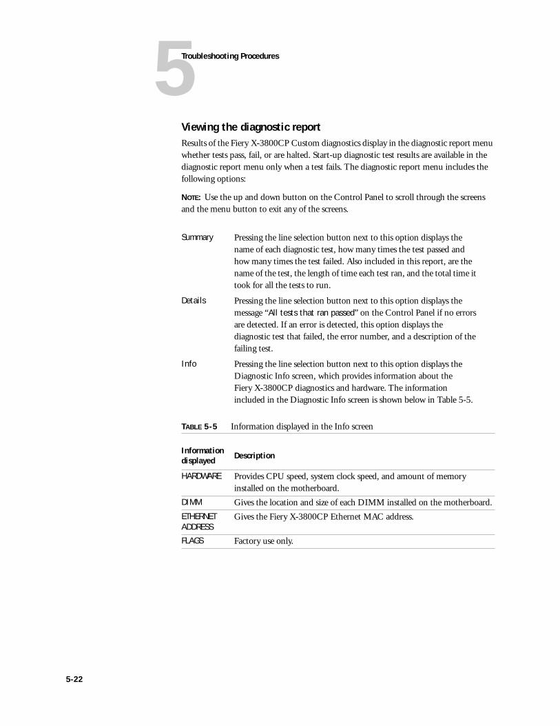
5Troubleshooting Procedures
Viewing the diagnostic reportResults of the Fiery X-3800CP Custom diagnostics display in the diagnostic report menu whether tests pass, fail, or are halted. Start-up diagnostic test results are available in the diagnostic report menu only when a test fails. The diagnostic report menu includes the following options:
NOTE: Use the up and down button on the Control Panel to scroll through the screens and the menu button to exit any of the screens.
Summary Pressing the line selection button next to this option displays the name of each diagnostic test, how many times the test passed and how many times the test failed. Also included in this report, are the name of the test, the length of time each test ran, and the total time it took for all the tests to run.
Details Pressing the line selection button next to this option displays the message “All tests that ran passed” on the Control Panel if no errors are detected. If an error is detected, this option displays the diagnostic test that failed, the error number, and a description of the failing test.
Info Pressing the line selection button next to this option displays the Diagnostic Info screen, which provides information about the Fiery X-3800CP diagnostics and hardware. The information included in the Diagnostic Info screen is shown below in Table 5-5.
TABLE 5-5 Information displayed in the Info screen
Information displayed Description
HARDWARE Provides CPU speed, system clock speed, and amount of memory installed on the motherboard.
DIMM Gives the location and size of each DIMM installed on the motherboard.
ETHERNET ADDRESS
Gives the Fiery X-3800CP Ethernet MAC address.
FLAGS Factory use only.
5-22
5Checking the entire Fiery X-3800CP system
Checking the entire Fiery X-3800CP systemThis phase of troubleshooting deals with problems with the entire system once the Fiery X-3800CP functions as a stand-alone unit.
Checking the printer interfaceAfter the Fiery X-3800CP starts up successfully as a stand-alone unit, power off the Fiery X-3800CP and connect the printer interface cable. You should make sure the Fiery X-3800CP is working properly with the printerbefore you connect it to the network. See “Connecting to the printer” on page 3-3.
Printing the Test Page
Once you have connected the Fiery X-3800CP to the printer, print the Test Page to make sure that the interface between the printer and the Fiery X-3800CP is working properly. If the Test Page does not print at all or has a low-quality image, the motherboard or printer interface cable may be faulty or the printer may not be functioning properly. In these cases, you should first check Fiery X-3800CP connections and then run the appropriate Custom diagnostics (see Table 5-4 on page 5-20).
TO PRINT THE TEST PAGE
1. Power on the printer and allow it to warm up.
2. Power on the Fiery X-3800CP.
Messages will appear on the Control Panel as the Fiery X-3800CP runs through its Start-up diagnostics.
3. Before proceeding, make sure that the printer is not in use.
5-23
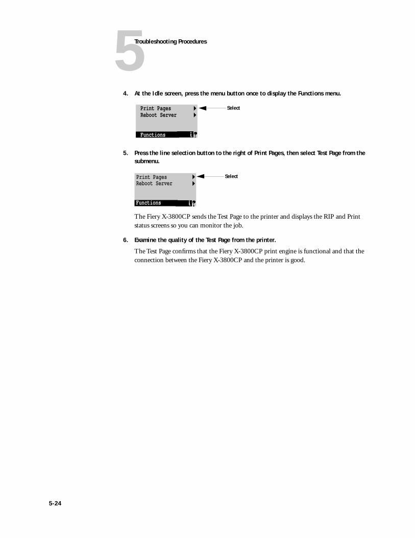
5Troubleshooting Procedures
4. At the Idle screen, press the menu button once to display the Functions menu.
5. Press the line selection button to the right of Print Pages, then select Test Page from the submenu.
The Fiery X-3800CP sends the Test Page to the printer and displays the RIP and Print status screens so you can monitor the job.
6. Examine the quality of the Test Page from the printer.
The Test Page confirms that the Fiery X-3800CP print engine is functional and that the connection between the Fiery X-3800CP and the printer is good.
Print PagesReboot Server
Functions
Select
Print PagesReboot Server
Functions
Select
5-24
5Checking the entire Fiery X-3800CP system
Checking network connectionsAfter the Fiery X-3800CP is connected to networked computers, printing problems may arise if the network hardware or software is not set up properly or doesn’t match network settings on the Fiery X-3800CP. Problems may also occur when printing from a specific application or printing a particular file.
Most of these problems show up as printing problems, and do not necessarily indicate a Fiery X-3800CP malfunction. The customer’s network administrator can eliminate many printing problems without requiring you to make a service call. The network administrator deals with:
• Print device error conditions.
• Conflicting network settings in Setup and on the customer’s attached PC.
• Printing problems caused by inappropriate Setup options.
• Application-specific printing errors caused by missing or incorrectly placed printer description files.
• Network connection problems that result in the Fiery X-3800CP not appearing in printer list on the customer’s networked computers.
5-25
Printing to the Fiery X-3800CPIf the user can print a Fiery X-3800CP Test Page, but cannot print a job from a workstation on the network, you may have to make a service call. However, first make sure the network administrator has done the following:
• Checked all components of the network including cables, connectors, terminators, network adapter boards, and network drivers.
• Activated the network and used it to communicate with other printers.
• Checked the corrective actions listed in the User Guide.
• Confirmed that the applicable network settings in Setup (such as AppleTalk zone, IP address, Subnet mask, and Gateway address) match the settings used in the network.
When you make a service call, check the back panel of the Fiery X-3800CP to make sure that the appropriate network connections are in place.
Intermittent print quality problems are difficult to trace. Before you try to troubleshoot print quality problems make sure that the printeritself does not need servicing or adjusting.
NOTE: EPS file generation is not completely standardized among applications. Some users may encounter problems while printing certain EPS files.
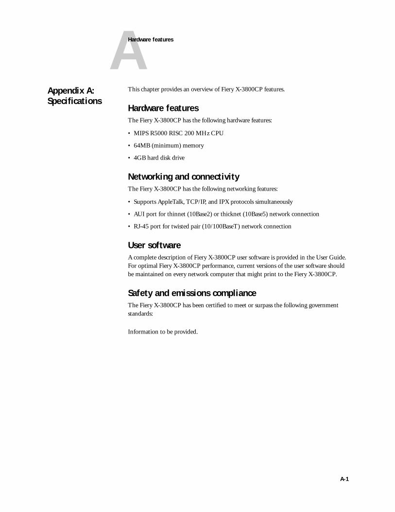
AHardware features
This chapter provides an overview of Fiery X-3800CP features.
Hardware featuresThe Fiery X-3800CP has the following hardware features:
• MIPS R5000 RISC 200 MHz CPU
• 64MB (minimum) memory
• 4GB hard disk drive
Networking and connectivityThe Fiery X-3800CP has the following networking features:
• Supports AppleTalk, TCP/IP, and IPX protocols simultaneously
• AUI port for thinnet (10Base2) or thicknet (10Base5) network connection
• RJ-45 port for twisted pair (10/100BaseT) network connection
User softwareA complete description of Fiery X-3800CP user software is provided in the User Guide. For optimal Fiery X-3800CP performance, current versions of the user software should be maintained on every network computer that might print to the Fiery X-3800CP.
Safety and emissions complianceThe Fiery X-3800CP has been certified to meet or surpass the following government standards:
Information to be provided.
Appendix A: Specifications
A-1

Index
Numerics10/100BaseT 2-4, 3-7, A-110Base2 2-4, 3-6, A-110Base5 2-4, 3-6, A-1Aaccessing internal components 4-3AC power cable 4-2, 4-10, 4-27, 4-32activity light 2-8, 3-2, 3-11, 4-14, 5-9Alert screen 3-12Alert status 3-13AppleTalk network 1-1AUI (attachment unit interface)
slide latch 3-6AUI port 2-8, A-1
Bback panel 2-8, 4-40battery 4-23BNC connector (on transceiver) 3-6boards
motherboard 4-10, 4-17user interface 4-10, 4-14
boxes, unpacking 2-6Burn-in diagnostics (factory use only) 5-17buttons
Control Panel 3-11line selection 2-8, 3-11, 4-14menu 2-8, 3-11, 4-14replacing 4-39up and down 2-8, 3-11, 4-14
Ccable connectors
BNC 3-6power supply cable 4-33reseating 4-9UIB 4-14
cablesAC power 4-2, 4-10, 4-27copier interface 5-6CPU fan 4-10exhaust fan 4-10ground 4-2, 4-10, 4-27HDD 4-2, 4-10, 4-36parallel 2-7, 3-8, 4-46, 5-6power 3-1, 5-6power supply 4-2, 4-10, 4-31SCSI interface 4-42UIB 4-2, 4-10, 4-14
cancel processing 3-14CD-ROM drive, connecting 4-42center frame 4-2
device side components 4-6motherboard side components 4-6
chassis, inspecting 5-7chassis cover 4-2, 4-5
removing 4-5chassis ground pin 4-32checking
cable connectors 4-9cables 4-9copier 2-3copier interface 5-6, 5-23customer site 2-3interface cables 5-6internal components 5-7internal connections 4-9network 2-4network connections 5-25
checking customer site 2-3attached parallel port devices 2-4external SCSI devices 2-4network 2-4power requirements 2-3printer requirements 2-3
I-1

I-2
Index
chipsCPU 1-2RipChip 1-2
color charts 3-15color management files 1-4color reference files 1-4components
accessing 4-3CPU fan 4-24DIMMs 4-11exhaust fan 4-24front panel 4-7hard disk drive 4-35motherboard 4-17power supply 4-30power switch 4-27user interface board 4-14
Configuration page 3-15configuring Setup 3-2, 3-6connecting
a PC to the parallel port 3-8CD-ROM drive 4-42to the network 3-5, 4-13to the printer 4-13
connections, networkthicknet (10Base5) 2-4, 3-5thinnet (10Base2) 2-4, 3-5twisted pair (10/100BaseT) 2-4, 3-5,
3-7connection verification steps 4-13Control Panel
activity light 2-8, 3-2, 5-9definition xiidisplay window 2-8line selection buttons 2-8, 3-11menu button 2-8troubleshooting 5-13up and down button 2-8using 3-10
control panel map 3-15copier interface cable 5-6copier interface port 5-6CPU 1-2CPU fan 4-24– 4-25
removing 4-26replacing 4-26
CPU fan cable 4-10
Custom diagnostics 5-17, 5-19IDE HDD 5-20MEM GND BOUNCE 5-20
customer expectationsnetwork administrator responsibility 2-5network impact 2-5printer availability 2-5
Ddamage, reporting xiii, 2-6Diagnostic Mix screen 5-18, 5-20diagnostic report
Details 5-22Info 5-22Summary 5-22
diagnosticsBurn-in (factory use only) 5-17Custom 5-17, 5-19Functional (factory use only) 5-17help 5-17report, viewing 5-22running manually 5-17, 5-21sets 5-17Start-up 3-1– 3-2, 5-17Start-up error numbers 5-10Start-up errors 5-9summary 5-18
DIMMs 1-2, 4-2, 4-11banks 4-21configurations 4-21removing 4-11, 4-22replacing 4-11, 4-22
display window 2-8handling xiiion user interface board 4-14
drivesCD-ROM 4-42hard disk 4-35
EEMI approvals A-1EMI shield
bottom 4-2, 4-31main 4-2, 4-31
EMI shieldstop 4-2
EPS files, printing 1-3error messages 5-14

Index
errorsStart-up diagnostics 5-9system 5-11
ESD (electrostatic discharge) safety precautions xiv
Ethernetcabling 3-5networks 3-5transceiver (for 10Base2/10Base5) 3-6
exhaust fan 4-24removing 4-24replacing 4-25
exhaust fan cable 4-10exploded view 4-2, 5-8
FFiery Downloader 1-3– 1-4Fiery Print Calibrator™ 1-4Fiery Spooler™ 1-4Fiery WebTools 1-4
Installer 1-4Status 1-4WebLink 1-4WebSetup 1-4WebSpooler 1-4
Fiery XJstartup 3-1
font list 3-15fonts
PostScript 1-1PostScript screen 1-4resident 1-1
Format Disk screen 4-43format options
Full 4-43Full&Verify 4-43Standard 4-43
front panel 2-8, 4-2accessing components 4-7components 4-38installing 4-8jewels 2-8removing 4-7
Functional diagnostics (factory use only) 5-17
functional diagram 1-3Functions menu 3-14– 3-15
Gground cable 4-2, 4-10, 4-27ground pin 4-10
chassis 4-32power supply 4-32
ground pin, chassis 4-29
Hhard disk drive 4-2, 4-10
carrier 4-2description 4-35HDD cable 4-2installing 4-37precautions 4-35reinstalling system software 4-35removing 4-35
hardware specifications A-1HDD cable 4-10, 4-36– 4-37
IInfo status 3-13initial installation, troubleshooting 5-1installation sequence 2-1– 2-2installing system software
parallel port requirements 4-46PC setup 4-47preparing for installation 4-42using the parallel port 4-50using the SCSI interface port 4-42
interface cables 5-6internal cable connections 4-10internal components, accessing 4-3internal components, checking 5-7internal connections 4-9IP address xiiiIPX (Novell) 1-1, 3-8
JJ10 (DIMM socket) 4-17J11 (AUI port) 4-17J12 (printer interface port) 4-17J16 (power supply cable) 4-17J17 (DIMM socket) 4-17J18 (fan cable) 4-17J2 (parallel port) 4-17J26 (DIMM socket) 4-17J27 (SCSI interface port) 4-17J28 (fan cable) 4-17
I-3
I-4
Index
J3 (HDD cable) 4-17J4 (UIB cable) 4-17J6 (RJ-45 port) 4-17J9 (DIMM socket) 4-17jewels 2-8, 4-39job log 3-15
LLAN (local area network) xiiilanguage selection 3-2line selection buttons 2-8, 3-11, 3-15, 4-14
Mmanually running diagnostics 5-17media package
System Software CD 2-6user documentation 2-6User Software CD 2-6
menu button 2-8, 3-11, 4-14menus
Functions 3-12, 3-14– 3-15Start Up 4-44
MIPS R5000 RISC CPU 1-2motherboard 4-10, 4-17
DIMMs 4-11, 4-21– 4-22installing 4-20removing 4-18– 4-19
Nnetwork administrator
configuring Setup 3-6installation 2-5
network connectionsAUI port 3-5checking 5-6, 5-25RJ-45 port (for 10/100BaseT) 3-5thicknet (10Base5) 2-4thinnet (10Base2) 2-4troubleshooting 5-25twisted pair (10/100BaseT) 2-4, 3-7
networksAppleTalk 1-1, A-1connecting to 3-5Ethernet 3-5, A-1Novell (IPX) 1-1, 3-8, A-1supported 1-1– 1-2, A-1TCP/IP 1-1, A-1
Novell (IPX) networks 1-1, 3-8
Oopening the server 4-4
Ppanels
back 2-8, 4-40front 2-8, 4-2
parallel cable 2-7, 3-8, 4-46, 5-6parallel port 2-8, 3-8, 5-6PC
connecting 3-8, 4-48requirements 4-46setting up 4-47
phone check 5-1Portable Document Format (PDF) 1-3port bracket 4-6ports
AUI 2-8, A-1copier interface 5-6parallel 2-8, 3-8, 5-6power 2-8printer interface 2-8, 4-17SCSI interface 2-8
PostScript files 1-3PostScript Printer Decscription file (PPD)
1-4PostScript screen fonts 1-4power
off the server 4-3power cable 3-1, 5-6power connector 2-8power supply 4-2, 4-10
cables connecting to 4-30description 4-30installing 4-32removing 4-31voltages 4-33
power supply cable 4-2, 4-10, 4-31– 4-32connectors 4-31pin assignments 4-34voltages 4-33
power supply ground pin 4-32power switch 2-8
cables connecting to 4-27description 4-27installing 4-28removing 4-28
precautions xiii
Index
printer interface port 2-8, 4-17printing
color charts 3-15Configuration page 3-15control panel map 3-15font list 3-15job log 3-15options 1-3PostScript files 1-3Print status 3-13problems 5-26Test Page 3-4, 4-13
printing problems 5-4Print Pages menu
color charts 3-15Configuration page 3-15control panel map 3-15font list 3-15job log 3-15Test page 3-15
Print status 3-13icon 3-13
Rreassembling the server 4-12– 4-13Reboot server 3-15removing components
battery 4-23CPU fan 4-26DIMMs 4-11exhaust fan 4-24front panel 4-7hard disk drive 4-35motherboard 4-18– 4-19power supply 4-31power switch 4-28user interface board 4-15
replacing componentsbattery 4-23CPU fan 4-26DIMMs 4-11exhaust fan 4-25front panel 4-8hard disk drive 4-37motherboard 4-20power supply 4-32power switch 4-28user interface board 4-16
report, diagnostic 5-22reseating cable connectors 4-9restarting 3-16restoring functionality 4-12RipChip 1-2RIP status 3-14RIP-While-Print 1-3RJ-45 port (for 10/100BaseT) A-1
Ssafety and emissions compliance A-1screens
Alert 3-12– 3-13Diagnostic Mix 5-18, 5-20Format Disk 4-43Functions 3-12, 3-15Idle 5-1Info 3-12– 3-13language 3-2Print 3-12– 3-13RIP 3-12, 3-14Select Language 3-2Setup 3-2TESTS FAILED 3-2Tests Failed 5-9, 5-18Tests Halted 5-18Tests Passed 5-18
SCSI interface port 2-8Select Language screen 3-2serial number 2-6server
components, functions of 1-2opening 4-4power off 4-3reassembling 4-12rebooting 3-15
service callsphone check 5-1service procedures 4-1tools required xv
service procedures 4-1accessing front panel components 4-7accessing internal components 4-3checking internal connections 4-9restoring functionality 4-12restoring functionality after service 4-12
Setup screen 3-2
I-5
I-6
Index
shipping boxcables 2-6contents 2-7media package 2-6
shutting down 3-16slide latch 3-6specifications, hardware A-1spooling 1-2startup
for installation 3-1language selection 3-2
Start-up diagnostics 5-1712C EEPROM 5-10BOOTROM 5-10ENET SLV REG 5-10error numbers 5-10errors 5-9IDE Chip 5-10MEM ADDRESS 5-10MEM DIMM INFO 5-10RTC R/W Reg 5-10RTC Self Test 5-10RTC Start 5-10running manually 5-21SCSI Chip 5-10SERIAL CHIP 5-10tests 5-10
Start Up menu 4-44status
Alert 3-13Info 3-13Print 3-13RIP 3-14
system errors 5-11system software installation
compatibilty 4-41error messages 5-14parallel port preparation 4-48parallel port requirements 4-46PC setup 4-47reminders 4-41SCSI interface port preparations 4-42using the parallel port 4-50using the SCSI interface port 4-44
TTCP/IP 1-1Test Page 3-15
printing 3-4TESTS FAILED screen 3-2Tests Failed screen 5-9, 5-18Tests Halted screen 5-18Tests Passed screen 5-18thicknet (10Base5) 2-4thinnet (10Base2) 2-4, 3-6tools required for service xvtroubleshooting
Control Panel 5-13network connections 5-6, 5-25operating problem 5-4operating problems 5-4phone check 5-1printing problems 5-26problems with initial installation 5-1process 5-1Start-up errors 5-9system errors 5-11system software installation 5-14
troubleshooting componentsAC power cable 5-11DIMMs 5-12exhaust fan 5-13fan cables 5-13ground cable 5-11HDD 5-13motherboard 5-12– 5-13power cable 5-11power supply 5-11– 5-12power supply cable 5-11– 5-12UIB 5-13UIB cable 5-13
twisted pair (10/100BaseT) 2-4, 3-7
Index
UU21 (CPU) 4-17UIB cable 4-2, 4-10, 4-14unpacking 2-6unshielded twisted pair (10/100BaseT) 3-7up and down button 2-8, 3-11, 4-14user interface board 4-10
activity light 4-14, 5-9buttons 4-39cable connector 4-14description 4-14display window 4-14enclosure 4-15installing 4-16line selection buttons 4-14menu button 4-14removing 4-15UIB cable 4-14up and down button 4-14
User Software CDcolor management files 1-4color reference files 1-4Fiery Downloader 1-4Fiery Print Calibrator™ 1-4Fiery Spooler™ 1-4PostScript Printer Description file (PPD)
1-4PostScript screen fonts 1-4
I-7


![Ricoh ChinaFiery JobFlow Base Fiery , FS200 Pro _Ei*fic Fiery Fiery Productivity Package Fiery JobFlow E] Fiery Windows Fiery Windows 7, 8, 8.1 s 10 32 fi/64 Google Mozilla Firefox](https://img.pdfslide.net/doc/110x75/611424df97efee38ef5fbef2/ricoh-fiery-jobflow-base-fiery-fs200-pro-eific-fiery-fiery-productivity-package.jpg)