Embed Size (px)
DESCRIPTION
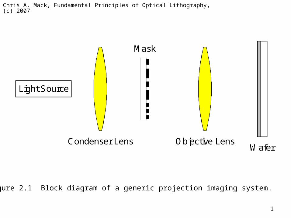
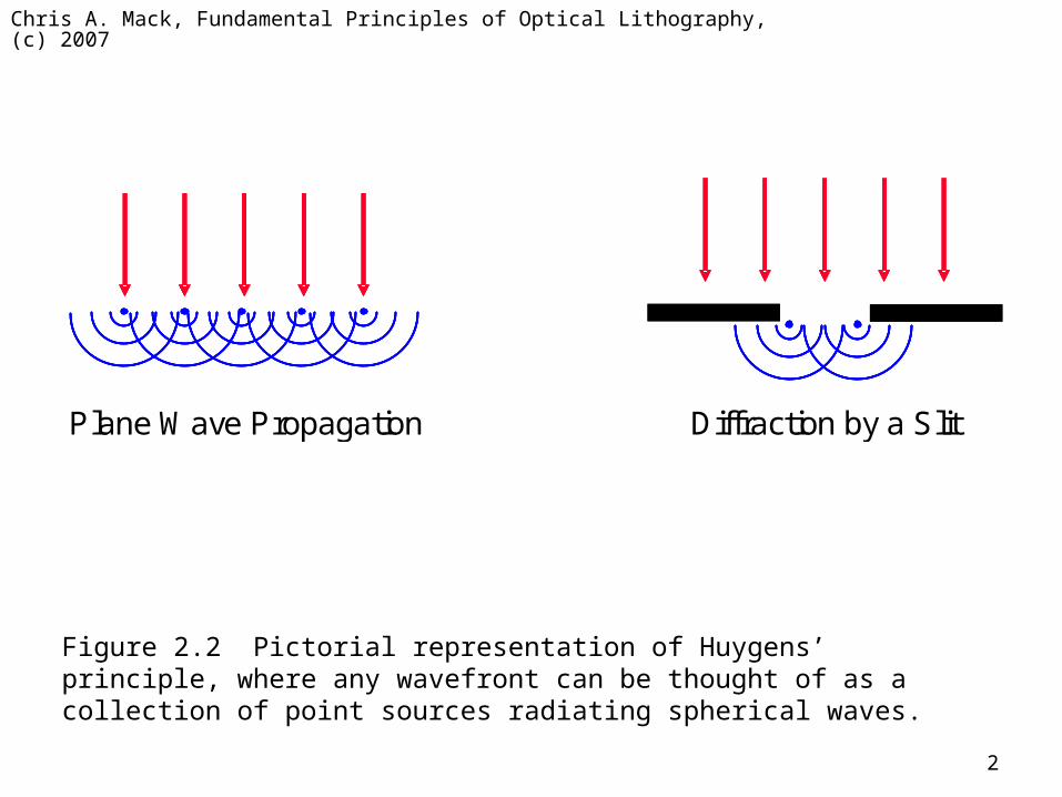
Figure 2.1 Block diagram of a generic projection imaging system. Figure 2.2 Pictorial representation of Huygens’ principle, where any wavefront can be thought of as a collection of point sources radiating spherical waves. - PowerPoint PPT Presentation
Citation preview
Chris A. Mack, Fundamental Principles of Optical Lithography, (c) 2007
1
Light Source
Condenser Lens
Mask
Objective Lens Wafer
Figure 2.1 Block diagram of a generic projection imaging system.
Chris A. Mack, Fundamental Principles of Optical Lithography, (c) 2007
2
Diffraction by a Slit Plane Wave Propagation
Figure 2.2 Pictorial representation of Huygens’ principle, where any wavefront can be thought of as a collection of point sources radiating spherical waves.
Chris A. Mack, Fundamental Principles of Optical Lithography, (c) 2007
3
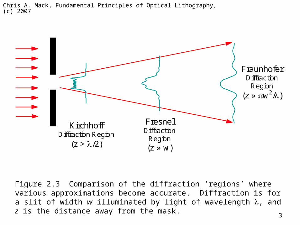
Fresnel Diffraction
Region (z » w)
Kirchhoff Diffraction Region
(z > /2)
Fraunhofer Diffraction
Region
(z » w2/)
Figure 2.3 Comparison of the diffraction ‘regions’ where various approximations become accurate. Diffraction is for a slit of width w illuminated by light of wavelength , and z is the distance away from the mask.
Chris A. Mack, Fundamental Principles of Optical Lithography, (c) 2007
4
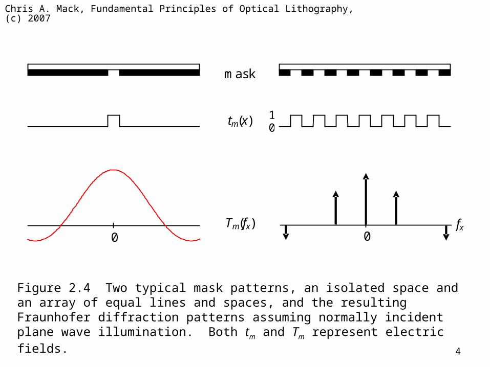
fx 0 0
mask
0 1
Tm(fx)
tm(x)
Figure 2.4 Two typical mask patterns, an isolated space and an array of equal lines and spaces, and the resulting Fraunhofer diffraction patterns assuming normally incident plane wave illumination. Both tm and Tm represent electric fields.
Chris A. Mack, Fundamental Principles of Optical Lithography, (c) 2007
5
0.0
0.2
0.4
0.6
0.8
1.0
-3 -2 -1 0 1 2 3
w fx
Inte
nsi
ty
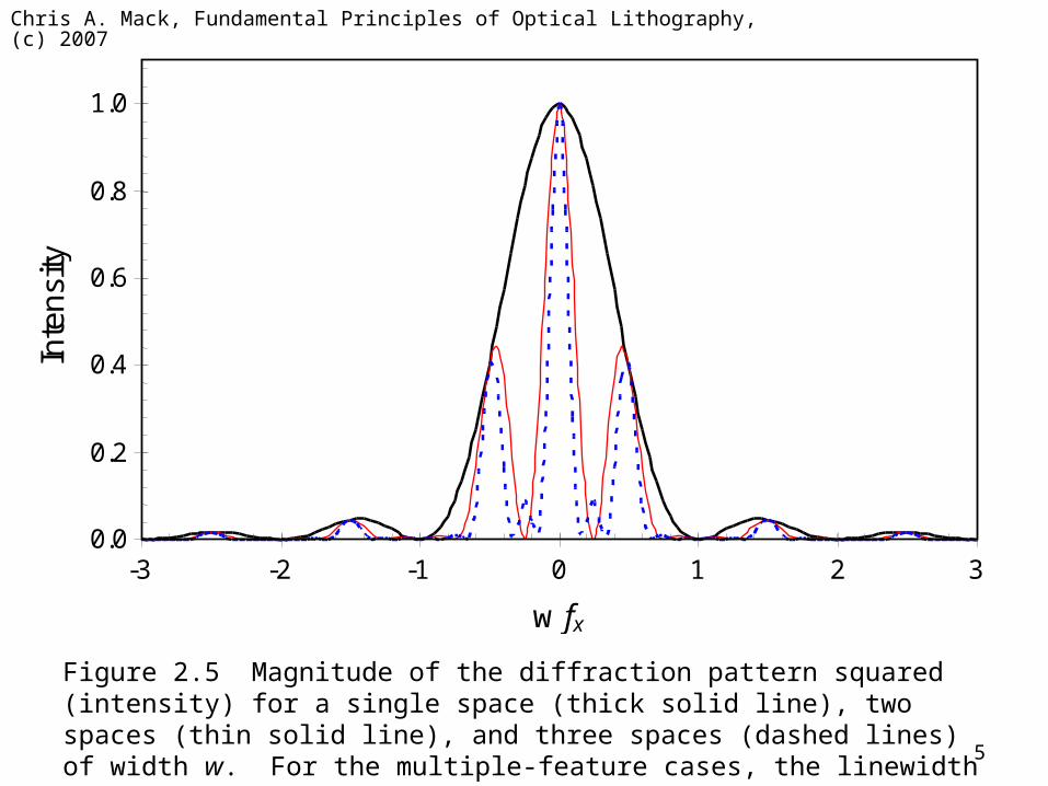
Figure 2.5 Magnitude of the diffraction pattern squared (intensity) for a single space (thick solid line), two spaces (thin solid line), and three spaces (dashed lines) of width w. For the multiple-feature cases, the linewidth is also equal to w.
Chris A. Mack, Fundamental Principles of Optical Lithography, (c) 2007
6
Aperture
(x’, y’)-plane
Object Plane
max
Objective Lens
Entrance Pupil
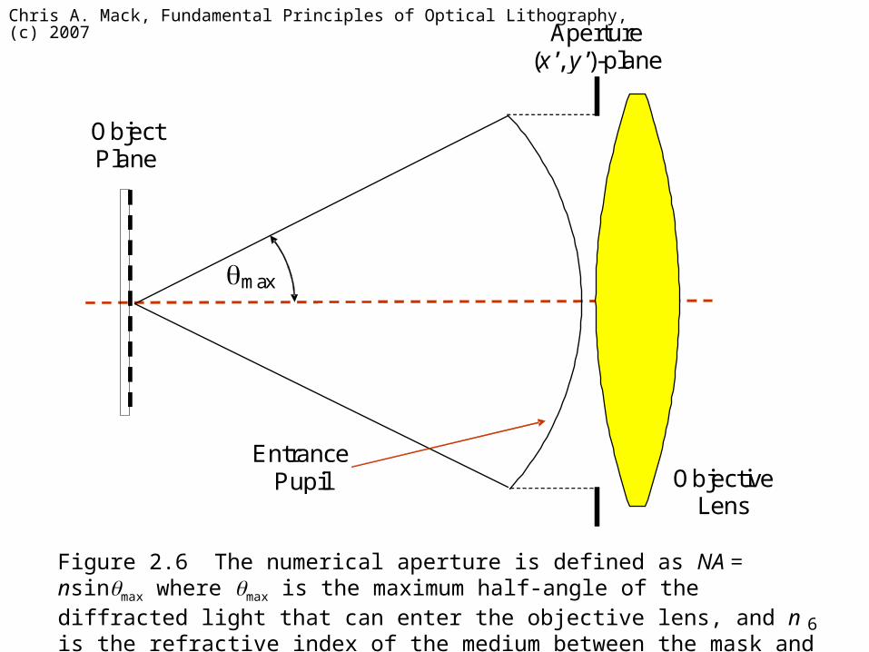
Figure 2.6 The numerical aperture is defined as NA = nsinmax where max is the maximum half-angle of the diffracted light that can enter the objective lens, and n is the refractive index of the medium between the mask and the lens.
Chris A. Mack, Fundamental Principles of Optical Lithography, (c) 2007
7
Objective Lens
Mask (Object)
Wafer (Image)
Entrance Pupil
Exit Pupil
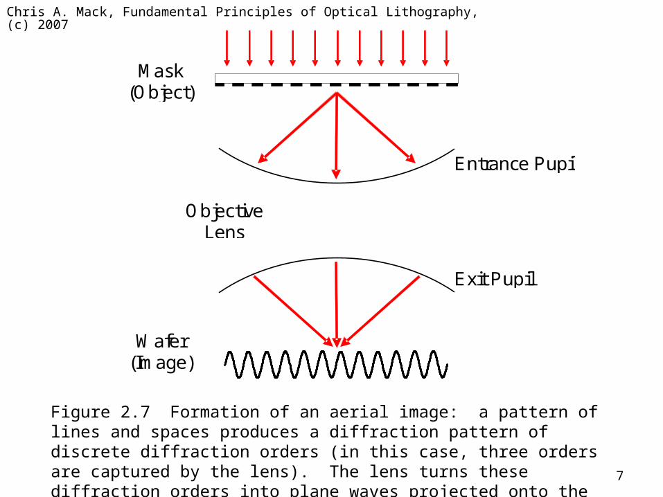
Figure 2.7 Formation of an aerial image: a pattern of lines and spaces produces a diffraction pattern of discrete diffraction orders (in this case, three orders are captured by the lens). The lens turns these diffraction orders into plane waves projected onto the wafer, which interfere to form the image.
Chris A. Mack, Fundamental Principles of Optical Lithography, (c) 2007
8
fx
Am
plit
ud
e
0 p
1p
2
p3
p1
p2
p3
0.5
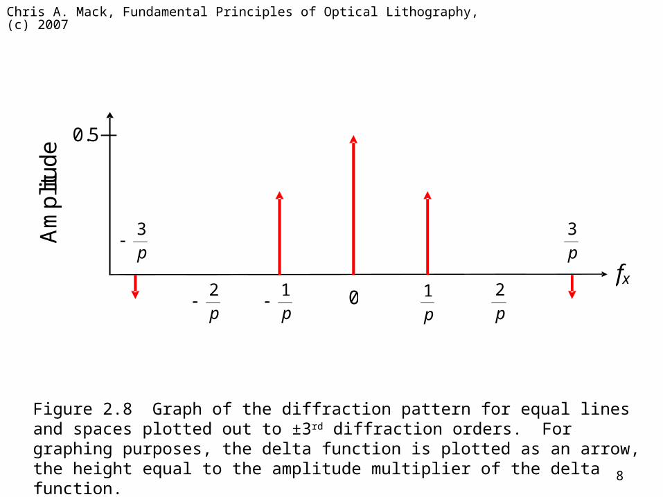
Figure 2.8 Graph of the diffraction pattern for equal lines and spaces plotted out to ±3rd diffraction orders. For graphing purposes, the delta function is plotted as an arrow, the height equal to the amplitude multiplier of the delta function.
Chris A. Mack, Fundamental Principles of Optical Lithography, (c) 2007
9
0.0
0.2
0.4
0.6
0.8
1.0
1.2
1.4
-w -w/2 0 w/2 w
Horizontal Position
Re
lativ
e In
ten
sity
N = 1 N = 3 N = 9
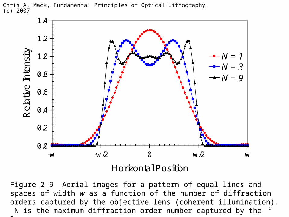
Figure 2.9 Aerial images for a pattern of equal lines and spaces of width w as a function of the number of diffraction orders captured by the objective lens (coherent illumination). N is the maximum diffraction order number captured by the lens.
Chris A. Mack, Fundamental Principles of Optical Lithography, (c) 2007
10
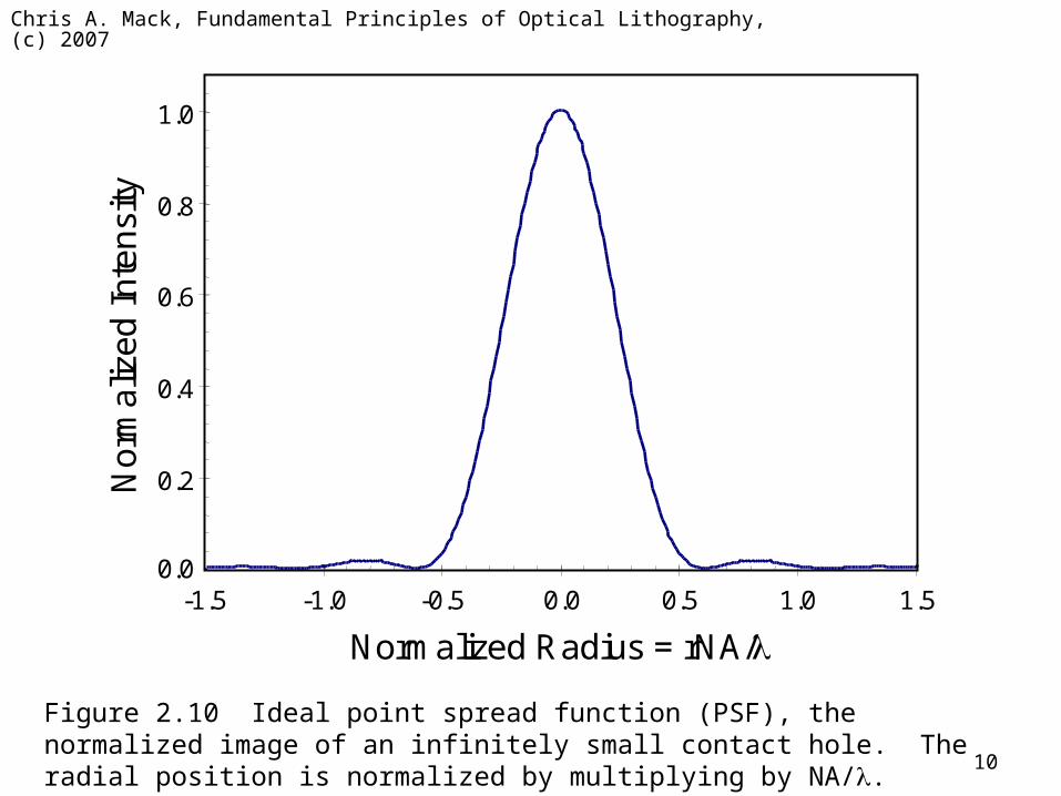
Figure 2.10 Ideal point spread function (PSF), the normalized image of an infinitely small contact hole. The radial position is normalized by multiplying by NA/.
0.0 -1.5 -1.0 -0.5 0.0 0.5 1.0 1.5
Normalized Radius = rNA/
0.2
0.4
0.6
0.8
1.0 N
orm
aliz
ed
In
ten
sity
Chris A. Mack, Fundamental Principles of Optical Lithography, (c) 2007
11
m
Entrance Pupil
Refractive index on mask side = nm
Refractive index on wafer side = nw
Exit Pupil
Aperture Stop
w
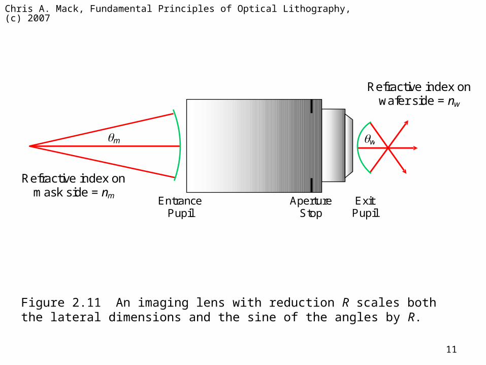
Figure 2.11 An imaging lens with reduction R scales both the lateral dimensions and the sine of the angles by R.
Chris A. Mack, Fundamental Principles of Optical Lithography, (c) 2007
12
0.8
1.0
1.2
1.4
1.6
1.8
2.0
0 0.2 0.4 0.6 0.8 1.0
sin(angle)
Pu
pil
Tra
nsm
ittan
ce
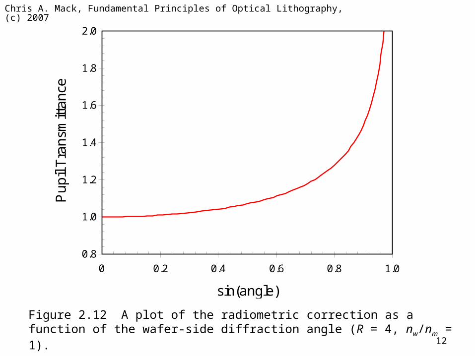
Figure 2.12 A plot of the radiometric correction as a function of the wafer-side diffraction angle (R = 4, nw/nm = 1).
Chris A. Mack, Fundamental Principles of Optical Lithography, (c) 2007
13
1.00
1.04
1.08
1.12
1.16
1.20
1.24
0.0 0.1 0.2 0.3 0.4 0.5 0.6 0.7 0.8
Wa
fer
Pla
ne O
pe
n F
ield
In
ten
sity
Partial Coherence
0.9
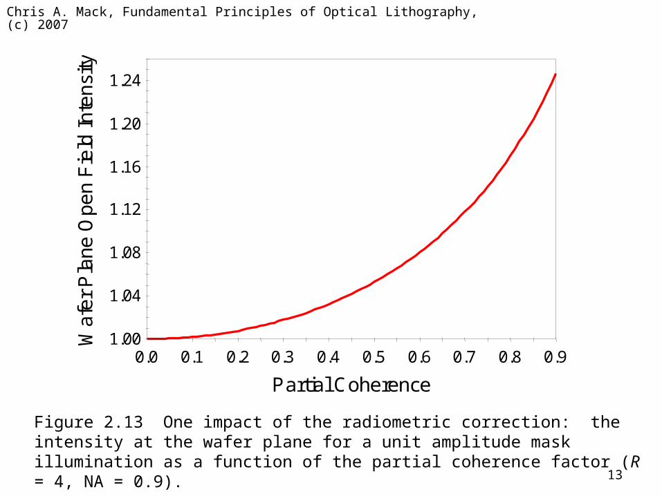
Figure 2.13 One impact of the radiometric correction: the intensity at the wafer plane for a unit amplitude mask illumination as a function of the partial coherence factor (R = 4, NA = 0.9).
Chris A. Mack, Fundamental Principles of Optical Lithography, (c) 2007
14
Diffraction Pattern
Lens Aperture
Mask Pattern (equal lines and spaces)
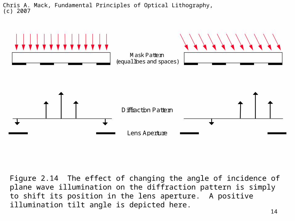
Figure 2.14 The effect of changing the angle of incidence of plane wave illumination on the diffraction pattern is simply to shift its position in the lens aperture. A positive illumination tilt angle is depicted here.
Chris A. Mack, Fundamental Principles of Optical Lithography, (c) 2007
15
Mask Pattern (equal lines and spaces)
Diffraction Pattern
Lens Aperture
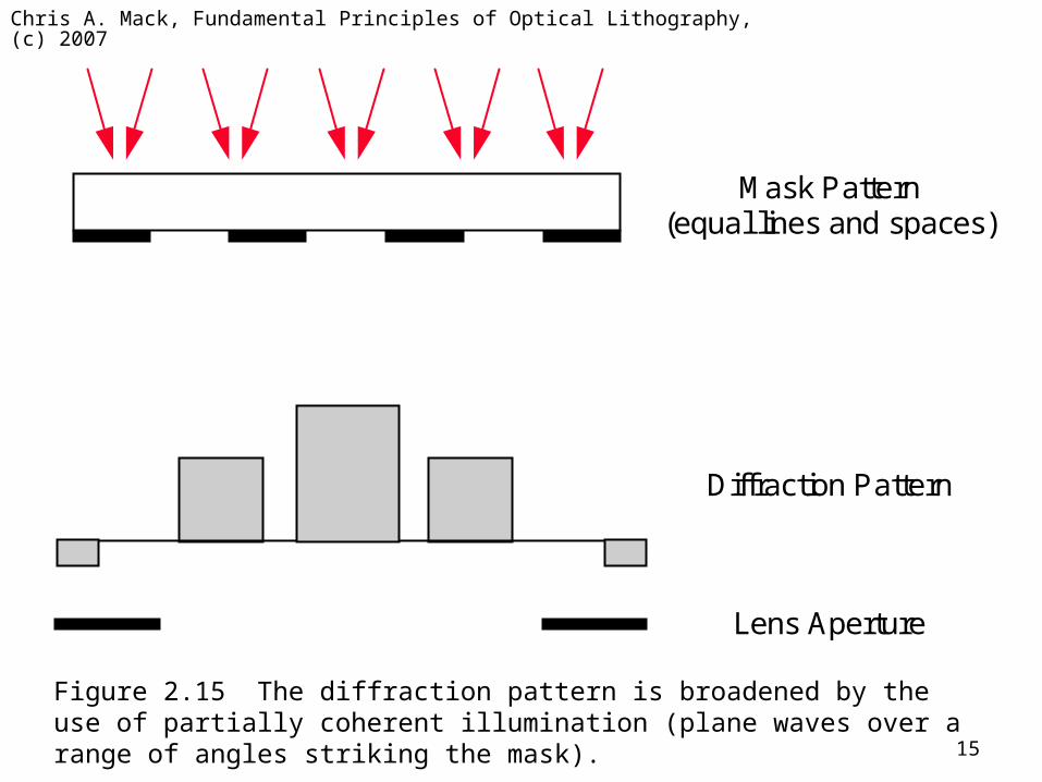
Figure 2.15 The diffraction pattern is broadened by the use of partially coherent illumination (plane waves over a range of angles striking the mask).
Chris A. Mack, Fundamental Principles of Optical Lithography, (c) 2007
16
-1st 0th +1st
Lens Aperture
-1st 0th +1st
Lens Aperture
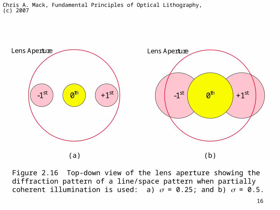
Figure 2.16 Top-down view of the lens aperture showing the diffraction pattern of a line/space pattern when partially coherent illumination is used: a) = 0.25; and b) = 0.5.
(a) (b)
Chris A. Mack, Fundamental Principles of Optical Lithography, (c) 2007
17
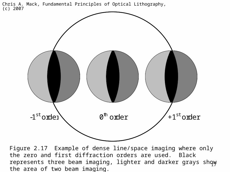
-1st order +1st order 0th order
Figure 2.17 Example of dense line/space imaging where only the zero and first diffraction orders are used. Black represents three beam imaging, lighter and darker grays show the area of two beam imaging.
Chris A. Mack, Fundamental Principles of Optical Lithography, (c) 2007
18
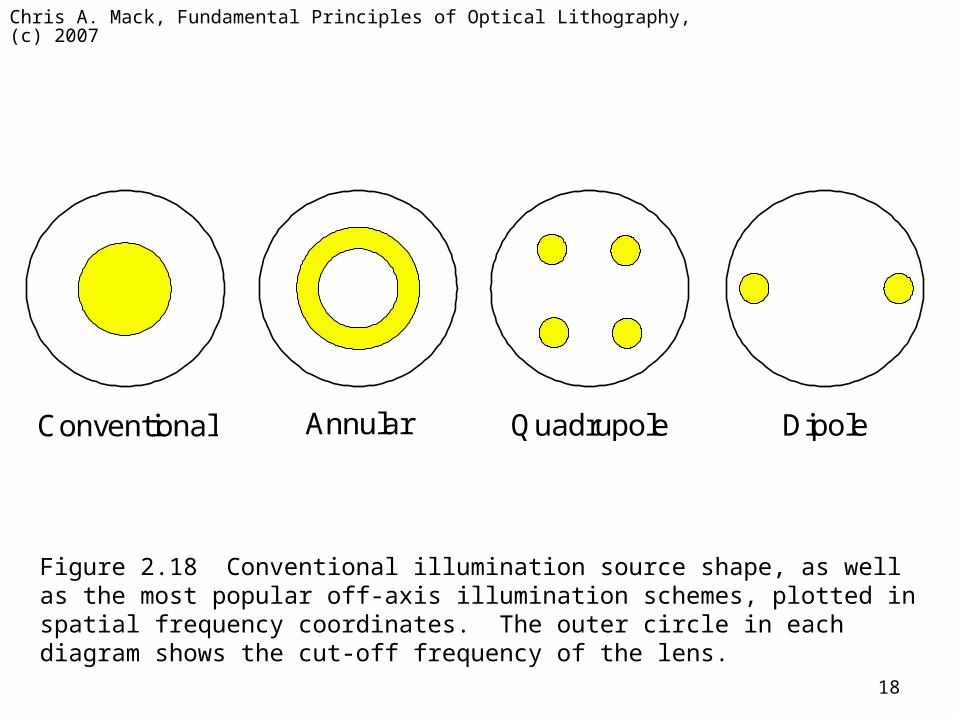
Quadrupole Annular Conventional Dipole
Figure 2.18 Conventional illumination source shape, as well as the most popular off-axis illumination schemes, plotted in spatial frequency coordinates. The outer circle in each diagram shows the cut-off frequency of the lens.
Chris A. Mack, Fundamental Principles of Optical Lithography, (c) 2007
19
-1.0 -0.5 0.0 0.5 1.0 -1.0
-0.5
0.0
0.5
1.0
X Pupil Position
Y P
upil
Pos
itio
n
-1.0 -0.5 0.0 0.5 1.0 -1.0
-0.5
0.0
0.5
1.0
X Pupil Position Y
Pup
il P
ositi
on
(a) (b)
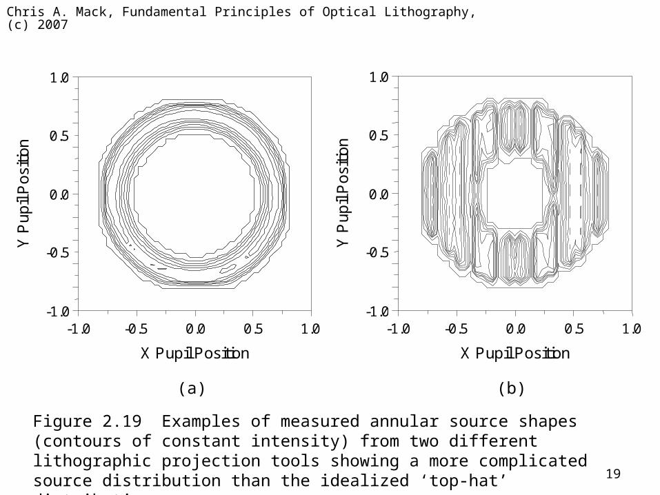
Figure 2.19 Examples of measured annular source shapes (contours of constant intensity) from two different lithographic projection tools showing a more complicated source distribution than the idealized ‘top-hat’ distributions.
Chris A. Mack, Fundamental Principles of Optical Lithography, (c) 2007
20
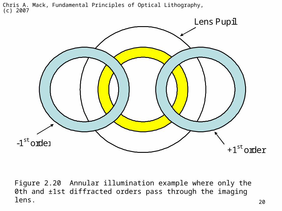
+1st order -1st order
Lens Pupil
Figure 2.20 Annular illumination example where only the 0th and ±1st diffracted orders pass through the imaging lens.
Chris A. Mack, Fundamental Principles of Optical Lithography, (c) 2007
21
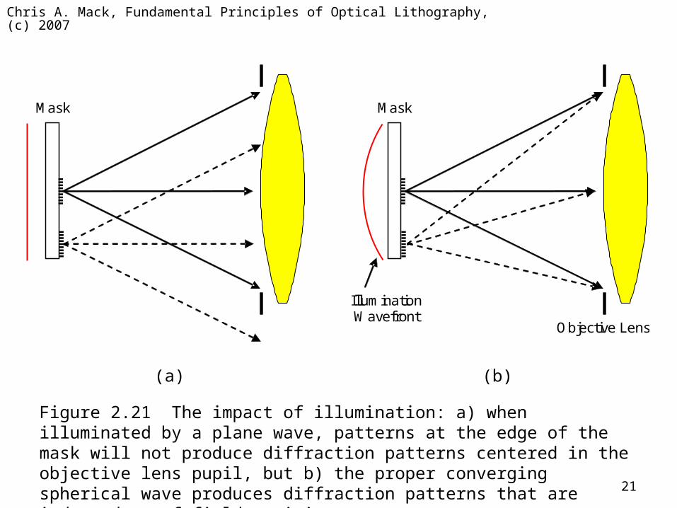
Mask
Mask
Illumination Wavefront
Objective Lens
(a) (b)
Figure 2.21 The impact of illumination: a) when illuminated by a plane wave, patterns at the edge of the mask will not produce diffraction patterns centered in the objective lens pupil, but b) the proper converging spherical wave produces diffraction patterns that are independent of field position.
Chris A. Mack, Fundamental Principles of Optical Lithography, (c) 2007
22
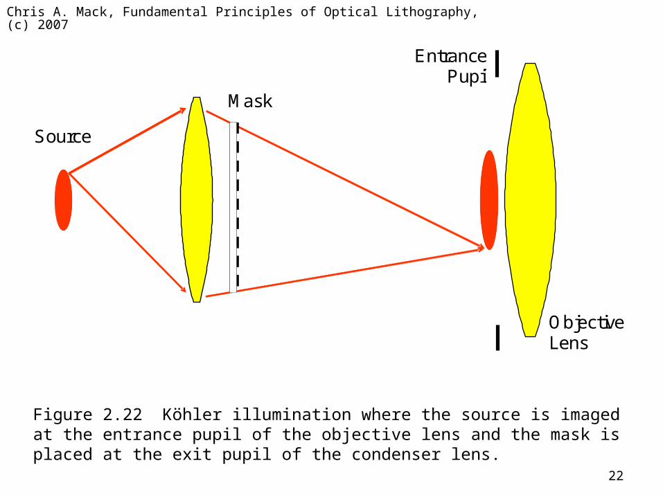
Mask
Entrance Pupil
Objective Lens
Source
Figure 2.22 Köhler illumination where the source is imaged at the entrance pupil of the objective lens and the mask is placed at the exit pupil of the condenser lens.
Chris A. Mack, Fundamental Principles of Optical Lithography, (c) 2007
23
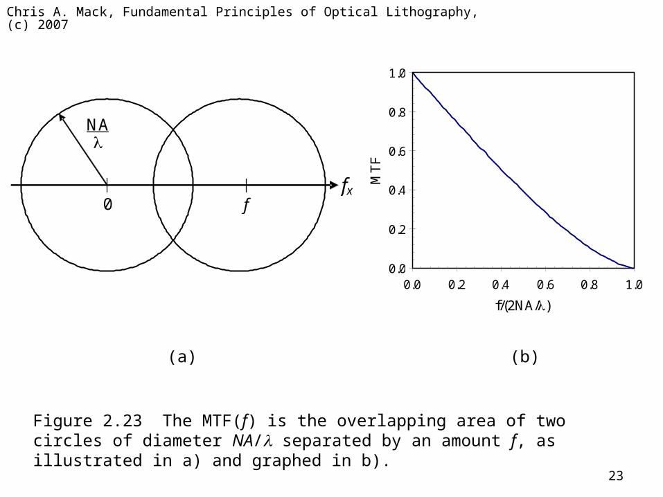
fx 0 f
NA
0.0
0.2
0.4
0.6
0.8
1.0
0.0 0.2 0.4 0.6 0.8 1.0
f/(2NA/)
MT
F
(a) (b)
Figure 2.23 The MTF(f) is the overlapping area of two circles of diameter NA/ separated by an amount f, as illustrated in a) and graphed in b).
Chris A. Mack, Fundamental Principles of Optical Lithography, (c) 2007
24
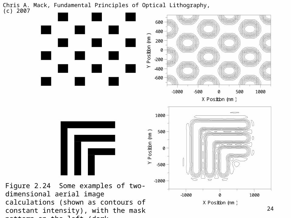
X Position (nm)
-1000 -500 0 500 1000
-600
-400
-200
200
400
600
0
Y P
ositi
on (
nm
)
-1000
-500
500
1000
0 Y
Posi
tion (
nm
)
X Position (nm)
-1000 0 1000
Figure 2.24 Some examples of two-dimensional aerial image calculations (shown as contours of constant intensity), with the mask pattern on the left (dark representing chrome).
Chris A. Mack, Fundamental Principles of Optical Lithography, (c) 2007
25
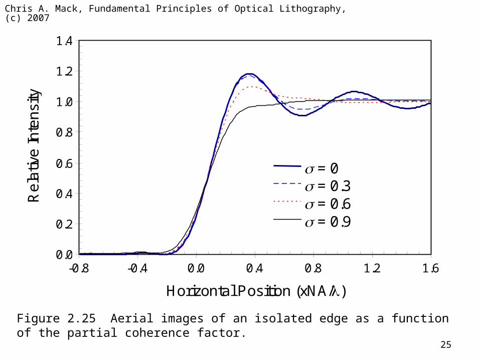
0.0
0.2
0.4
0.6
0.8
1.0
1.2
1.4
-0.8 -0.4 0.0 0.4 0.8 1.2 1.6
Horizontal Position (xNA/)
Re
lativ
e In
ten
sity
= 0 = 0.3 = 0.6 = 0.9
Figure 2.25 Aerial images of an isolated edge as a function of the partial coherence factor.