Embed Size (px)
Citation preview
3-21
Figure 3-10. Construction of the monolithic square vault for WM-189 (left) and WM-190 (right). (63-4240)
3-22
3.4.2 30,000-Gallon Tanks
The four 30,000-gal tanks (WM-103 through -106) were constructed in 1954-1955. Originally, the tanks were designed to store first-cycle wastes from the new (at the time) zirconium (WM-103 through WM-105) and stainless-steel (WM-106) fuel reprocessing systems. Those wastes were chemically different and more corrosive than the Al wastes for which the 300,000-gal tanks had been originally designed. Therefore, the new wastes were stored in the 30,000-gal tanks until corrosion and waste compatibility tests proved they could be safely stored in the 300,000-gal tanks. The 30,000-gal tanks are horizontal, cylindrical tanks. The tanks are about 11.5 ft in diameter and 38 ft long and are constructed of Type 316L stainless steel. They have thicker plate than the 300,000-gal tanks and have a sleeve covering the tank weld seams for added corrosion and leak protection. All four tanks have cooling coils and off-gas condensers. The tanks vented to the vessel off-gas treatment systems located in CPP-604 and CPP-649. The tanks have instrumentation to monitor the temperature, level, and density of solution within the tank. WM-103 and WM-104 each have four steam jets, and WM-105 and WM-106 each had two steam jets to transfer waste from the tanks.
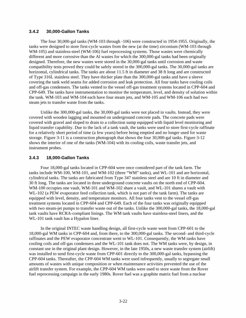
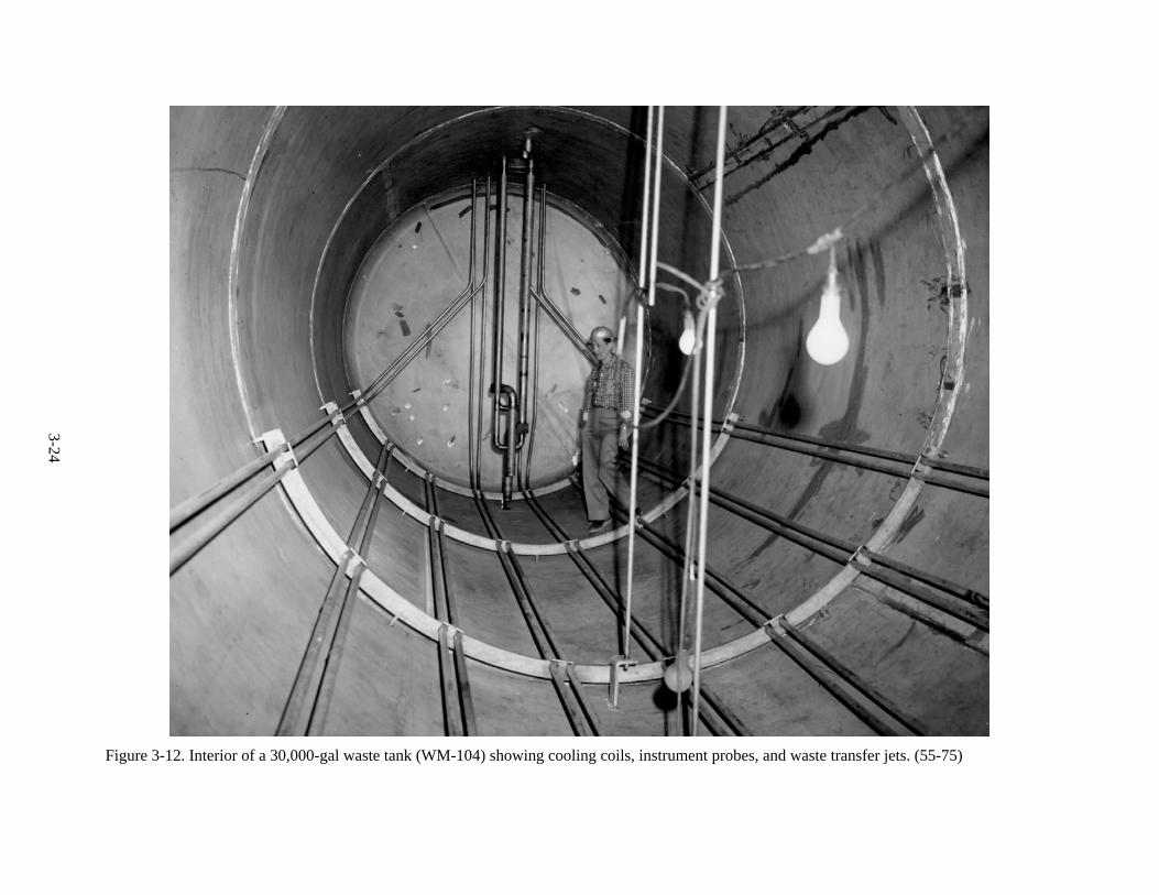
Unlike the 300,000-gal tanks, the 30,000-gal tanks were not placed in vaults. Instead, they were covered with wooden lagging and mounted on underground concrete pads. The concrete pads were covered with gravel and sloped to drain to a collection sump equipped with liquid level monitoring and liquid transfer capability. Due to the lack of a tank vault, the tanks were used to store first-cycle raffinate for a relatively short period of time (a few years) before being emptied and no longer used for waste storage. Figure 3-11 is a construction photograph that shows the four 30,000-gal tanks. Figure 3-12 shows the interior of one of the tanks (WM-104) with its cooling coils, waste transfer jets, and instrument probes.
3.4.3 18,000-Gallon Tanks
Four 18,000-gal tanks located in CPP-604 were once considered part of the tank farm. The tanks include WM-100, WM-101, and WM-102 (three “WM” tanks), and WL-101 and are horizontal, cylindrical tanks. The tanks are fabricated from Type 347 stainless steel and are 10 ft in diameter and 30 ft long. The tanks are located in three underground concrete vaults on the north end of CPP-604. WM-100 occupies one vault, WM-101 and WM-102 share a vault, and WL-101 shares a vault with WL-102 (a PEW evaporator feed collection tank, which is not part of the tank farm). The tanks are equipped with level, density, and temperature monitors. All four tanks vent to the vessel off-gas treatment systems located in CPP-604 and CPP-649. Each of the four tanks was originally equipped with two steam-jet pumps to transfer waste out of the tanks. Unlike the 300,000-gal tanks, the 18,000-gal tank vaults have RCRA-compliant linings. The WM tank vaults have stainless-steel liners, and the WL-101 tank vault has a Hypalon liner.
In the original INTEC waste handling design, all first-cycle waste went from CPP-601 to the 18,000-gal WM tanks in CPP-604 and, from there, to the 300,000-gal tanks. The second- and third-cycle raffinates and the PEW evaporator concentrate went to WL-101. Consequently, the WM tanks have cooling coils and off-gas condensers and the WL-101 tank does not. The WM tanks were, by design, in constant use in the original plant design. However, in the late 1950s, a new waste transfer system (airlift) was installed to send first-cycle waste from CPP-601 directly to the 300,000-gal tanks, bypassing the CPP-604 tanks. Thereafter, the CPP-604 WM tanks were used infrequently, usually to segregate small amounts of wastes with unique composition or when maintenance activities prevented the use of the airlift transfer system. For example, the CPP-604 WM tanks were used to store waste from the Rover fuel reprocessing campaign in the early 1980s. Rover fuel was a graphite matrix fuel from a nuclear
3-23
Figure 3-11. Installation of the four 30,000-gal tanks WM-103 through WM-106 (top to bottom). (13249)
3-24
Figure 3-12. Interior of a 30,000-gal waste tank (WM-104) showing cooling coils, instrument probes, and waste transfer jets. (55-75)
3-25
rocket program. The Rover waste composition differed from most other tank farm wastes, so it was stored in the CPP-604 WM tanks prior to being calcined. Over time, piping changes removed the second- and third-cycle waste from WL-101, but it continued to receive PEW evaporator concentrate.
The four 18,000-gal tanks are now considered part of the PEW evaporator system. WL-101 continues to receive and store PEW evaporator concentrate, while the WM tanks may store PEW evaporator feed or concentrate.
3.4.4 Tank Farm Piping and Secondary Containment
The waste transfer piping in the tank farm was constructed with stainless steel to withstand the corrosive nature of the waste. The transfer piping, like the waste tanks, was constructed over a number of years by different projects that used different designs. The differences in the various projects’ designs are evident in the secondary containment (encasement) systems. The tank farm waste transfer piping used six types of encasements:
1. Split clay-tile pipe
2. Split steel trough
3. Stainless-steel-lined concrete trough
4. Stainless-steel pipe
5. Embedded in concrete
6. Carbon steel.
Each encasement type is described below in further detail, including where and when the style of encasement was used and the configuration’s strengths and weaknesses. Any liquid waste that leaked into the encasement system originally drained to a nearby valve box, tank, or tank vault. To be RCRA-compliant, valve box sumps draining to tank vault sumps (not RCRA-compliant) have been plugged. The waste transfer piping had leak detection equipment that has been upgraded over time. The leak detection consists of a combination of radiation and level detection instrumentation to detect the presence of a release from the primary piping system.
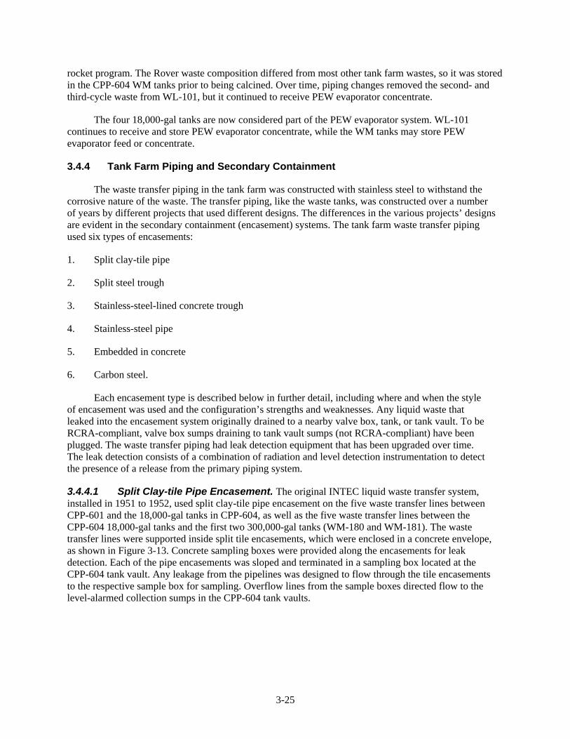
3.4.4.1 Split Clay-tile Pipe Encasement. The original INTEC liquid waste transfer system, installed in 1951 to 1952, used split clay-tile pipe encasement on the five waste transfer lines between CPP-601 and the 18,000-gal tanks in CPP-604, as well as the five waste transfer lines between the CPP-604 18,000-gal tanks and the first two 300,000-gal tanks (WM-180 and WM-181). The waste transfer lines were supported inside split tile encasements, which were enclosed in a concrete envelope, as shown in Figure 3-13. Concrete sampling boxes were provided along the encasements for leak detection. Each of the pipe encasements was sloped and terminated in a sampling box located at the CPP-604 tank vault. Any leakage from the pipelines was designed to flow through the tile encasements to the respective sample box for sampling. Overflow lines from the sample boxes directed flow to the level-alarmed collection sumps in the CPP-604 tank vaults.
3-26
Figure 3-13. Cross section of a split clay-tile pipe encasement.
The design of the split clay-tile encasement was not completely compatible with the waste. The clay pipe itself was compatible with the waste, but the putty used to seal sections of the split tile piping was not resistant to nitric acid. In addition, the rigid nature of the clay pipe made it susceptible to cracking due to soil settling and compaction. Failure of tile encasements north of CPP-604 caused the deep contamination in Site CPP-79 (deep), which extends below Site CPP-28.
Due to its inferior design, all of the tile-pipe-encased lines between CPP-601 and CPP-604, and between CPP-604 and WM-181 and WM-180, were replaced with upgraded systems or capped and removed from service.
Two short sections of tile encasement remain around stub outs (one each on the north side of WM-180 and WM-181) that were installed as spares with the construction of WM-180 and WM-181 and were later connected to the main tank farm waste transfer system. These two sections of encasement contain only welded stainless-steel pipe. They neither contain nor serve as a drainage path for valves or other equipment with a high potential to leak. Prior to about 1990 (when rigorous RCRA assessments and compliance began), the two lines were used infrequently for waste transfers into WM-180 and WM-181. Other waste transfer lines, into the south side of the tanks, were normally used to transfer waste into those two tanks. Similarly installed primary waste piping elsewhere at INTEC has not leaked, and there is no reason to suspect the primary piping in this case has leaked. Because the primary system has likely not leaked, there is correspondingly little potential for any environmental contamination. Although there is no reason to believe the primary waste lines within those two encasements have ever leaked, the two lines have had strict administrative controls that virtually eliminated their use for approximately the past 15 years.
3-27
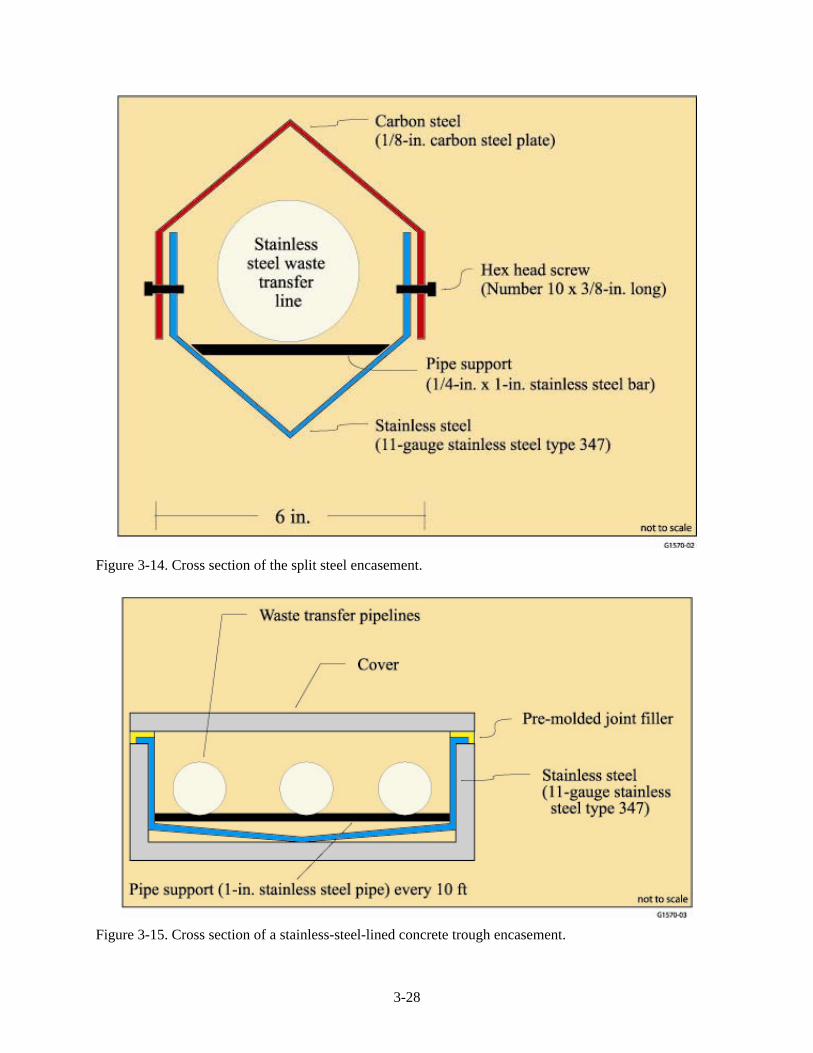
3.4.4.2 Split Steel Trough Encasement. In 1955, a major expansion program was completed that included the construction of three new waste storage tanks, WM-182, -183, and -184. The project also installed substantial amounts of additional waste transfer piping and associated valve boxes. The project used three different pipe encasement designs. Most of the encasement was a stainless-steel-lined concrete trough (discussed in the following section). A small portion of piping had stainless-steel pipe-in-pipe encasements (also discussed in a later section). However, two waste lines (totaling approximately 160 ft) used a split steel encasement in an area located between CPP-604 and WM-181. This design consisted of two parts: (1) a lower trough section of welded stainless steel in which the stainless-steel transfer pipe was supported and (2) an upper section of carbon steel that overlapped and was pinned to the lower stainless-steel trough by screws (Figure 3-14). The carbon-steel cover was painted with two coats of bitumastic paint.
Although the lower portion of this encasement (into which any leaks would fall) was compatible with the waste in the transfer piping, the carbon-steel upper cover was susceptible to corrosion from waste fumes or from contact with the soil. A construction error in the installation of this encasement occurred when a pilot hole for the encasement-connecting screws penetrated the waste piping. This allowed waste to leak from the transfer line. Eventual failure of the carbon-steel encasement cover allowed soil to collapse into the lower stainless-steel trough. This blocked the leak drainage path and lead to the contamination of Site CPP-28. All of this type of encasement was removed and replaced following the discovery of the CPP-28 contamination site in 1974.
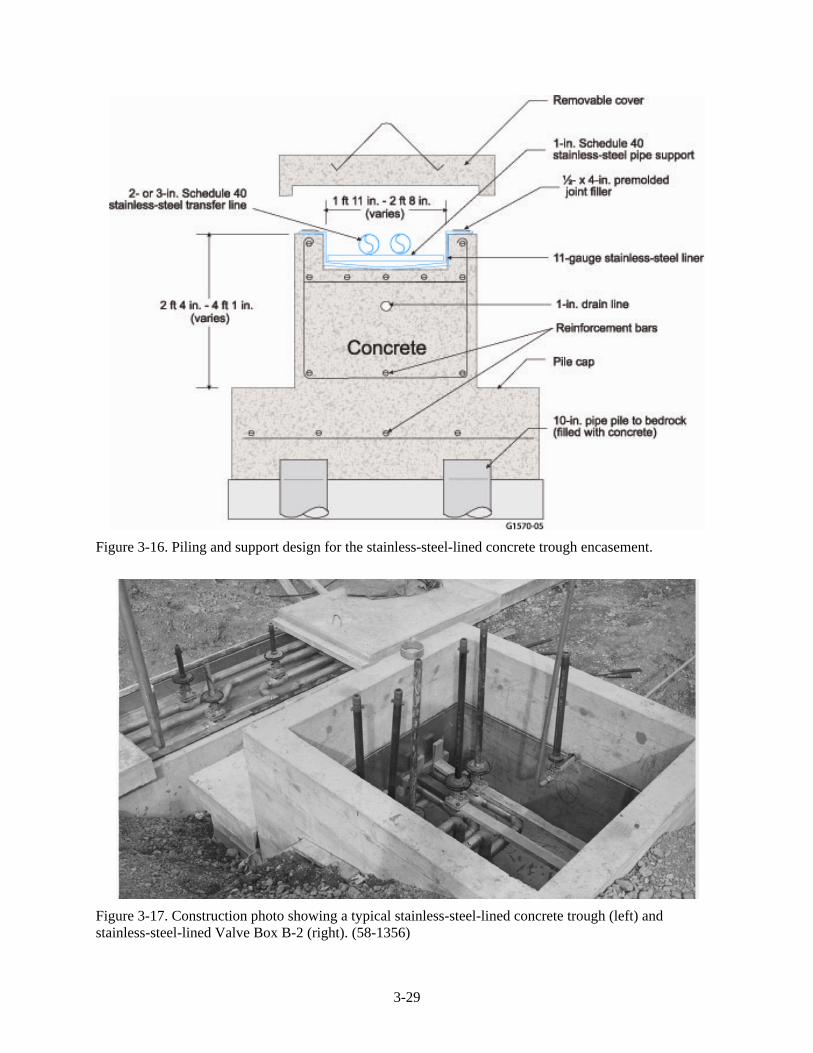
3.4.4.3 Stainless-Steel-Lined Concrete Trough Encasement. Beginning with the 1955 tank farm expansion, stainless-steel-lined concrete troughs were used for encasements of several waste transfer lines, especially in areas where several waste transfer lines were co-located and could be grouped together in one encasement. This design consisted of a pile-supported, reinforced-concrete trough that was lined with stainless steel. Such an encasement typically contained two to four waste transfer lines. Figures 3-15 and 3-16 are schematics of typical stainless-steel-lined concrete troughs. Figure 3-17 is a construction photo showing such a trough. The troughs sloped to sampling sumps or valve boxes and had removable concrete covers. Stainless-steel-lined concrete troughs were used as encasements by several projects. They were used to encase the first-cycle waste transfer lines from CPP-601 to the 30,000-gal waste tanks and to encase most of the waste transfer trunk lines that ran the length of the tank farm between the 300,000-gal tanks. This secondary containment design has been trouble-free and has had no known releases to the environment.
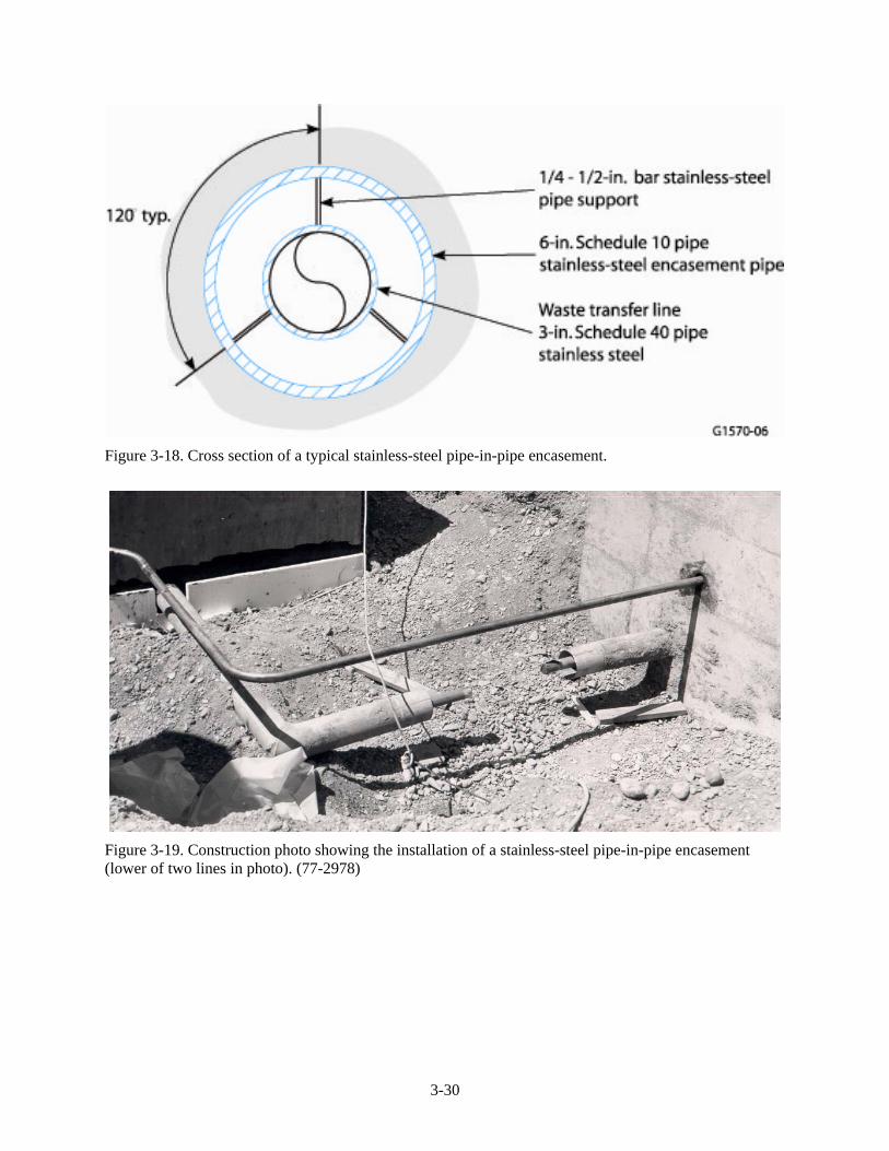
3.4.4.4 Stainless-Steel Pipe Encasement. Starting in 1955, the secondary containment for some waste transfer piping began using a stainless-steel pipe-in-pipe encasement design. This design, along with the stainless-steel-lined trough, was used by subsequent projects for the bulk of the tank farm waste transfer line encasements. The pipe-in-pipe design has been trouble-free and has had no known releases to the environment. The stainless-steel pipe-in-pipe design is shown in a schematic in Figure 3-18. Figure 3-19 is a construction photograph showing a pipe-in-pipe system being installed in the tank farm.
3.4.4.5 Concrete-Embedded Encasement. The eight lines used to fill WM-187 through WM-190 (two lines per tank) are embedded in concrete for a few inches where the lines leave valve boxes and enter the tank vault. The valve box and tank vault share a common wall at that point. Given the configuration, any leakage at that location would result in waste entering the tank vault; there is very little, if any, possibility of leaking waste entering the soil. As a result, there are no plans to change this configuration, other than cease use of those four tanks per the requirements of the Consent Order.
3-28
Figure 3-14. Cross section of the split steel encasement.
Figure 3-15. Cross section of a stainless-steel-lined concrete trough encasement.
3-29
Figure 3-16. Piling and support design for the stainless-steel-lined concrete trough encasement.
Figure 3-17. Construction photo showing a typical stainless-steel-lined concrete trough (left) and stainless-steel-lined Valve Box B-2 (right). (58-1356)
3-30
Figure 3-18. Cross section of a typical stainless-steel pipe-in-pipe encasement.
Figure 3-19. Construction photo showing the installation of a stainless-steel pipe-in-pipe encasement (lower of two lines in photo). (77-2978)
3-31
3.4.4.6 Carbon-Steel Pipe Encasement. The original waste transfer lines into WM-180 and WM-181 tanks had the clay pipe encasements (discussed previously) except for the very short sections of line that penetrated the vault walls. The vault wall penetration used carbon-steel sleeves. Therefore, each of the clay pipe encasements associated with WM-180 and WM-181 also had a short section of carbon-steel encasement. The lines with the inferior combined tile/carbon-steel encasements were replaced or removed from service as previously described.
3.4.4.7 Tank Farm Valve Boxes. The initial tank farm construction (WM-180 and WM-181) had minimal piping, piping junctions, and waste transfer possibilities. Therefore, there were no valves or valve boxes. As the number of tanks increased, the waste transfer piping became more complex, allowing transfers of waste from tank to tank and between various facilities. This required valves to direct waste among the several possible destinations.
Initially, most valves were located in underground stainless-steel-lined concrete troughs, in the stainless-steel pipe-in-pipe encasements, or in completely underground valve boxes. However, such valve locations required a significant amount of work (excavation) to access the valve when repair work was needed. It became evident that some other valve access method was needed. Therefore, over time, all valves were relocated into valve boxes with grade-level access. This provided ready access to the valves for maintenance purposes. The valve boxes provided secondary containment and leak detection for valves and waste transfer lines located with the valve boxes.
The valve boxes, like the tank vaults, were built by a number of different contractors with a number of different designs. There was no standard system for valve box identification. Each valve box was identified by a letter followed by a sequential number. In general, the A series boxes are the oldest boxes and were installed in the mid 1950s. The B series boxes were installed in the late 1950s and early 1960s. The C series boxes were installed beginning in a major upgrade project in 1977 and have continued to the present. There are some exceptions to these generalizations. For example, Box A-9 was installed in the 1980s, and B-11 was installed in the late 1970s.
The valve boxes are typically constructed of reinforced concrete and lined with stainless steel. The valve boxes vary in size, depending on the number of valves and amount of piping contained within the boxes. Most of the boxes are about 6 ft long and 6 ft wide. The box depth varies depending on the elevation of the valves and transfer lines within the box. Typically, the valve boxes extend approximately 1 ft above grade and have an access port to provide personnel access to the valves within the box.
One notable exception to the preceding general information on valve boxes was a manhole just north of CPP-712. In the mid 1970s, INTEC installed a service waste diversion system to ensure contaminated liquids were not inadvertently released to the environment. The system temporarily used WM-181 as the collection tank for diverted water. Water diverted into WM-181 was contaminated with residue in WM-181 and could not be returned to the service waste system. Instead, it was pumped to the PEW evaporator via piping connections in a gravel-bottomed manhole near CPP-712. Valve leaks in that manhole created contamination at Site CPP-16.
3.5 Past Tank Composition and Usage
The composition of the liquid waste in a given tank varied over time as most of the tanks were filled, emptied, and refilled several times over the life of the facility. SNF reprocessing and the PEW evaporator operation generated wastes, while the calcination facilities removed wastes from the tanks. Sometimes, tanks were filled, emptied, and then refilled with the same type of waste (Al, Zr, SBW). At other times, tanks were filled with one type of waste (such as Al), emptied, and then refilled with a different waste (such as Zr or SBW). The major sources of the waste were previously discussed and
3-32
typical waste compositions were given in Table 3-1. Each tank has a different waste storage history. In general, the tanks equipped with cooling coils stored first-cycle raffinate and those without cooling coils stored SBW. However, as time progressed, some of the cooling-coil-equipped tanks stored SBW. This was because the calciners rapidly processed first-cycle raffinate to maintain waste storage capacity for SNF reprocessing. Calcination of SBW was slower and proceeded at a lower priority for most of the INTEC history. This resulted in a buildup in the volume of SBW over time, and some of the tanks with cooling capability were eventually used for SBW storage.
3.5.1 300,000-Gallon Tank Usage
The following summarizes the use of the eleven 300,000-gal tanks (WM-180 through WM-190):
• WM-180 was put in service in 1954. Initially, it stored first-cycle raffinate from reprocessing Al-clad fuel. The Al waste was calcined in 1966 and 1967. The tank stored SBW waste thereafter. It was emptied and filled three times. The tank has been emptied and cleaned and is currently awaiting final closure activities.
• WM-181 was put in service in 1953. This tank was never used to store first-cycle raffinate. It stored SBW for its entire history except from 1973 to 1977, when it was used as a temporary service waste diversion tank. The tank was emptied and filled with SBW four times. The tank has been emptied and cleaned and is currently awaiting final closure activities.
• WM-182 was put in service in 1956. Initially, it stored first-cycle raffinate from reprocessing Al-clad fuel. Over time, it was emptied and filled repeatedly and stored first-cycle raffinates from Al- and Zr-clad fuel reprocessing. The tank has been emptied and cleaned and is currently awaiting final closure activities.
• WM-183 was put in service in 1958. Initially, it stored first-cycle raffinate from reprocessing Al-clad fuel. Over time, it was emptied and filled repeatedly and stored first-cycle raffinate from Al- and stainless-steel (electrolytic) -clad fuel reprocessing. It also stored SBW. The tank has been emptied and cleaned and is currently awaiting final closure activities.
• WM-184 was put in service in 1958. This tank never stored first-cycle raffinate. It stored SBW for its entire history. This tank had the fewest number of filling/emptying cycles. It was initially filled, partially emptied, and then refilled, for a total of only two filling/emptying cycles. The tank has been emptied and cleaned and is currently awaiting final closure activities.
• WM-185 was put in service in 1959. Initially, it stored first-cycle raffinate from reprocessing Al-clad fuel. Over time, it was emptied and filled repeatedly. It stored first-cycle raffinate from Al- and Zr-clad fuel reprocessing. It also stored SBW. The tank has been emptied and cleaned and is currently awaiting final closure activities.
• WM-186 was put into service in 1962. This tank does not contain cooling coils and was designed to store low-activity waste (SBW). However, its initial service was to store about 70,000 gal of first-cycle raffinate from Al-clad fuel reprocessing. That waste was sent to WM-186 from WM-187 when the contents of WM-187 began siphoning into the tank vault. Operations personnel initially mistook the siphon event as a leaking tank and began transferring waste from WM-187 to WM-186. The first-cycle waste was later removed from WM-186 and the tank was used to store SBW thereafter. It was filled and emptied twice with SBW. The tank has been emptied and cleaned and is currently awaiting final closure activities.
3-33
• WM-187 was put into service in 1959. Initially, it stored first-cycle raffinate from reprocessing Al-clad fuel. Over time, it was emptied and filled repeatedly and stored first-cycle raffinate from Al- and Zr-clad fuel reprocessing. With the change in INTEC mission in the 1990s and beginning of the tank farm closure project, it received tank “heels” (residues from other “empty” tanks) and flush solution from tanks that were cleaned in preparation for RCRA closure. The dilute tank-cleaning waste was sent from WM-187 to the NWCF for concentration in the high-level liquid waste evaporator (HLLWE). In this fashion, the tank has been repeatedly filled and emptied with tank closure flush solution. The tank currently (December 2005) contains over 280,000 gal of waste. The waste includes SBW that was removed from other tanks and concentrated in the NWCF evaporator. The tank also contains the bulk of the solids and waste heels that were originally in the “cleaned” tanks, WM-180 through WM-186.
• WM-188 was put in service in 1959. Initially, it stored first-cycle raffinate from reprocessing Al-clad fuel. Over time, it was emptied and filled repeatedly and stored first-cycle raffinate from Al- and Zr-clad fuel reprocessing. WM-188 was the last tank to store first-cycle raffinate. In 1996, the HLLWE became operational and concentrated wastes from WM-183 and WM-189. The concentrate went to WM-188. The concentrate from WM-183 and WM-189 contained a significant amount (about 31 volume percent) of waste that was derived from first-cycle raffinate. That waste was calcined by February 1998, which completed a state Settlement Agreement to calcine all nonsodium high-level waste by June 30, 1998 (DOE 1995). After February 1998, the tank was refilled with SBW as part of the effort to empty the pillar-and-panel tanks. The tank currently (December 2005) contains about 282,000 gal of SBW that was removed from some of the “cleaned” tanks and concentrated in the NWCF evaporator.
• WM-189 was put in service in 1964. Initially, it stored first-cycle raffinate from reprocessing Zr-clad fuel. Over time, it was emptied and filled repeatedly, storing primarily Zr waste. In the 1990s, after fuel reprocessing ceased, the tank was emptied of first-cycle raffinate and refilled with SBW as part of the effort to empty the pillar-and-panel tanks. The tank currently (December 2005) contains about 282,000 gal of SBW that was removed from some the “cleaned” tanks and concentrated in the NWCF evaporator.
• WM-190 was never used to store radioactive waste after its construction in 1964. Instead, it was retained as the designated spare tank for use in emergencies (such as a leak in another tank). Until the early 1980s, the tank contained approximately 7,000 gal of water (snowmelt and rainfall) that had leaked through the tank vault roof and was transferred into the tank. In 1980, the water was sampled and found contaminated (0.016 Ci/L Cs-137) as a result of leakage through and cycling of the isolation valves on the tank fill lines. The tank was emptied to its current volume of about 500 gal in 1982 using a temporary pump to transfer as much liquid as possible from the tank to the PEW evaporator.
3.5.2 30,000-Gallon Tank Usage
The four 30,000-gal waste tanks (WM-103 through WM-106) were designed to store the (at the time) “new” wastes from the dissolution of Zr- and stainless-steel-clad fuels. Those wastes were different from the first-cycle Al raffinate for which the 300,000-gal tanks were originally designed. The 30,000-gal waste tanks were filled with first-cycle Zr and stainless-steel (sulfate) raffinates in the late 1950s and early 1960s as originally designed. However, due to the lack of a tank vault to contain a leak, the tanks were emptied, flushed with water, and never used again for waste storage (except for a few weeks in 1983) by the mid-1970s. Thus, they were in service for a relatively short period of time, about 15 years.
3-34
In 1983, WM-103 through WM-105 were used for a few weeks to store PEW evaporator condensate that normally would have been sent to the injection well via the service waste system. At that time, the injection well casing had failed and PEW evaporator condensate was not sent to the injection well while repairs were made to the well casing. Some of the PEW evaporator condensate was stored in the 30,000-gal tanks. The evaporator condensate was removed from the 30,000-gal tanks after the injection well liner was repaired. The tanks were flushed with water after storing PEW evaporator condensate, and the residue was sampled and determined to be nonhazardous (Matule 1990). The tanks are currently empty and awaiting RCRA closure activities. The following summarizes their usage:
• WM-103 was placed in service in 1956. Initially, it stored first-cycle raffinate from reprocessing Zr-clad fuel. It was emptied in 1965 and refilled with first-cycle stainless-steel (sulfate) raffinate. That waste was removed in 1974 and the tank was rinsed with water. It has not been used for waste storage (except the PEW evaporator condensate in 1983 as explained earlier) since that time.
• WM-104 was placed in service in 1960. Initially, it stored first-cycle raffinate from reprocessing Zr-clad fuel. It was emptied in 1965, rinsed with water, and has not been used for waste storage (except the PEW evaporator condensate in 1983 as explained earlier) since that time.
• WM-105 was placed in service in 1959. Initially, it stored uranium-bearing solution (not waste) generated during the October 1959 criticality at INTEC. That solution was removed for uranium recovery in November 1959. The tank began storing first-cycle raffinate from reprocessing Zr-clad fuel in December 1959. It was emptied in 1974 and the tank was rinsed with water. It has not been used for waste storage (except the PEW evaporator condensate in 1983 as explained earlier) since that time.
• WM-106 was placed in service in 1959. It stored first-cycle raffinate from reprocessing stainless-steel-clad fuel (sulfate). It was emptied in 1974 and the tank was rinsed with water. It has not been used for waste storage since that time.
3.5.3 18,000-Gallon Tanks Usage
The four 18,000-gal tanks in CPP-604 (WM-100, WM-101, WM-102, and WL-101) were part of the original INTEC construction and were used to store the first radioactive waste generated. The original INTEC design sent first-cycle raffinate from CPP-601 to WM-100, WM-101, and WM-102. From there, the waste was transferred to the 300,000-gal tanks.
In the early to mid-1950s, all first-cycle waste went in and out of the three CPP-604 first-cycle waste tanks. In 1957, an airlift transfer system was installed that could send CPP-601 first-cycle waste directly to the 300,000-gal tanks, bypassing the CPP-604 tanks. Thereafter, the airlift was used for most first- (and second-) cycle raffinate transfers because it avoided the steam condensate dilution of the waste associated with the steam-jet transfers from the CPP-604 tanks. After 1957, the CPP-604 first-cycle waste tanks were used infrequently, such as when valve maintenance shut down the normal transfer route or to segregate small amounts of unique wastes (such as Rover fuel waste in the early 1980s).
Tank WL-101 has been in constant use since 1953. The original INTEC design sent second- and third-cycle raffinate, along with the PEW evaporator concentrate, to WL-101. From WL-101, waste was transferred to the 300,000-gal tanks. Later, piping changes eliminated the second- and third-cycle waste from WL-101, but it has continued to receive PEW evaporator concentrate.
3-35
The CPP-604 tanks are in cells with RCRA-compliant secondary containment and are being permitted as part of the PEW evaporator system instead of being closed like the other tank farm vessels. Thus, they remain in service.
3.6 Current Mission and Future of the Tank Farm
The current INTEC mission includes management and storage of the liquid radioactive waste remaining in the tank farm and small amounts that may be generated in the future. Currently, three of the 300,000-gal waste tanks (WM-187 through WM-189) store waste. A fourth tank, WM-190, is in service as an empty spare tank. The other 300,000-gal tanks have been cleaned and are awaiting additional RCRA closure activities. The four 30,000-gal tanks have also been cleaned and emptied and are awaiting additional closure activities. The four 18,000-gal tanks in CPP-604 will remain in service as part of the (permitted) PEW evaporator system. The volume of waste in the tank farm will fluctuate as decontamination activities generate wastes and waste evaporation reduces the total waste volume. The final disposition of the waste remaining in the 300,000-gal tanks will be determined in the future.
The 300,000- and 30,000-gal tanks are being closed in accordance with the 1992 Consent Order (DOE-ID 1992) and its subsequent modifications. The closure will follow the Hazardous Waste Management Act (HWMA)/RCRA closure performance standards identified in DEQ-approved HWMA/RCRA closure plans. These closure plans recognize that the contaminated soils in the tank farm are undergoing investigation by the CERCLA program, and the plans will not duplicate the efforts of the CERCLA investigation and any follow-on remediation actions for the contaminated soils. The tank closure must also meet the requirements of DOE O 435.1, “Radioactive Waste Management.”
The general approach for tank farm closure begins with removing the waste from the tanks and ancillary systems, decontaminating the system components, and sampling the decontamination residuals. The sample data from the decontamination are compared to site-specific action levels.
When all of the tanks and ancillary systems are decontaminated, final tank farm closure and closure certification will occur. The tank farm will be closed as an HWMA/RCRA interim status unit (IDAPA 58.01.05.009 [40 CFR 265]). Upon meeting the performance criteria for waste removal and system decontamination, documentation will be provided to DEQ certifying the performance of partial closure.
Phase 1 of the tank farm closure began in 2001 with pillar-and-panel-vaulted tanks WM-182 and WM-183 (DOE-ID 2001). Subsequently, similar closure plans were developed for other groups of tanks, and closure activities began on the remaining pillar-and-panel-vaulted tanks (WM-184, WM-185, and WM-186) (DOE-ID 2003); the monolithic-vaulted tanks (WM-180 and WM-181); and the four 30,000-gal tanks (WM-103 through WM-106).a Closure activities for the tanks have included removing the bulk waste solution, removing residual waste from the tanks, cleaning of ancillary systems, inspecting the tanks, and sampling residual (decontamination) solution in the tanks and vault sumps.
Risk evaluations made prior to the closure activities assumed the postcleaning solid residue remaining in the tanks (which would contain the bulk of the radioactivity and RCRA constituents) could
a. DOE/NE-ID-11134, Hazardous Waste Management Act/Resource Conservation and Recovery Act Closure Plan for the Idaho Nuclear Technology and Engineering Center Tanks WM-103, WM-104, WM-105, WM-106 and WM-181 (pending approval by DEQ).
DOE/NE-ID-11167, Hazardous Waste Management Act/Resource Conservation and Recovery Act Closure Plan for the Idaho Nuclear Technology and Engineering Center Tank WM-180 (pending approval by DEQ).
3-36
be as much as 1 in. deep. However, tank cleaning experience has shown the solid residue to be no more than 1/8 in. deep (Portage 2004a). To date, postcleaning tank residue sample results indicate the tank cleaning efforts have successfully met the performance criteria (Portage 2004b).
Phase 1 will include isolating the closed system to eliminate any future inflow to the tanks, ancillary equipment, or secondary containment. The approved Closure Plan for WM-182 and WM-183 (DOE-ID 2001) calls for filling the tanks, vaults, and waste lines with grout to isolate the systems and fill void spaces. However, the original grouting schedule was suspended due to litigation concerning waste classification under DOE O 435.1. Per the Closure Plan (DOE-ID 2001), Phase 1 will not be completed until the tanks are grouted. In the interim, cleaning of remaining pillar-and-panel-vaulted tanks (WM-184, WM-185, and WM-186); the two octagonal monolithic vaulted tanks (WM-180 and WM-181); and the four 30,000-gal tanks (WM-103 through WM-106) was performed.
One issue must be resolved before complete closure of the tank farm can be accomplished. This issue involves tank farm residuals waste determination. The National Defense Authorization Act of 2005, Section 3116, provides the process for waste determination and public review (Public Law 108-375). Steam reforming was selected to treat the remaining liquid radioactive waste (SBW) stored in the tank farm. However, the SBW treatment has not yet been RCRA permitted. Until the tanks are emptied, the remaining 300,000-gal waste tanks containing SBW cannot be grouted. Because grouting is part of the clean closure performance standards for the Tank Farm Facility, grouting may commence upon approval of Section 3116, Waste Determination.
3.7 References
40 CFR 265, 2006, “Interim Status Standards for Owners and Operators of Hazardous Waste Treatment, Storage, and Disposal Facilities,” Code of Federal Regulations, Office of the Federal Register, April 2006.
DOE O 435.1, Change 1, 2001, “Radioactive Waste Management,” U.S. Department of Energy, August 28, 2001.
DOE, 1995, Settlement Agreement, U.S. Department of Energy, Environmental Management; U.S. Department of the Navy, and Idaho Department of Health and Welfare, October 16, 1995.
DOE-ID, 1992, Consent Order to the Notice of Noncompliance, Idaho Code § 39-4413, U.S. Department of Energy Idaho Operations Office; U.S. Environmental Protection Agency, Region 10; and Idaho Department of Health and Welfare, April 3, 1992.
DOE-ID, 1999, Third Modification to Consent Order, U.S. Department of Energy Idaho Operation Office; U.S. Environmental Protection Agency, Region X; and Idaho Department of Health and Welfare, April 20, 1999.
DOE-ID, 2001, Idaho Hazardous Waste Management Act/Resource Conservation and Recovery Act Closure Plan for Idaho Nuclear Technology and Engineering Center Tanks WM-182 and WM-183, DOE/ID-10802, Rev. 0, U.S. Department of Energy Idaho Operation Office, November 2001.
DOE-ID, 2003, Idaho Hazardous Waste Management Act/Resource Conservation and Recovery Act Closure Plan for the Idaho Nuclear Technology and Engineering Center Tanks WM-184, WM-185, and WM-186, DOE/ID-11067, U.S. Department of Energy Idaho Operation Office, May 2003.
3-37
Ermold, L. F., INEL, to P. S. Yela, INEL, May 8, 1992, “Production Department Monthly Report,” LFE-111-92.
IDAPA 58.01.05.009, 2006, “Interim Status Standards for Owners and Operators of Hazardous Waste Treatment, Storage and Disposal Facilities,” Idaho Department of Administrative Procedures Act, Idaho Department of Environmental Quality, April 11, 2006.
Loos, R. L., CCN 47582, to Frank C. Holmes, DOE Idaho, January 29, 2004, “INTEC Tank Farm Operating History Report (INTEC-WP-03-021) and Completion of Sodium-Bearing Waste Treatment Process Project Milestone,” CCN 47582.
Matule, A. J., WINCO, to D. C. Machovec, WINCO, September 26, 1990, “Solids Sampling of WM-103 through -106,” AJM-20-90.
Portage, 2004a, “WM-182 Tank Solid and Liquid Volume Estimates and Post-Decontamination Radionuclide Inventories with Comparisons to Performance Assessment Modeling Results,” PEI-EDF-1009, Portage Environmental, Inc., September 13, 2004.
Portage, 2004b, Data Quality Assessment Report for the Post-Decontamination Characterization of the Contents of Tank WM-182 at the Idaho Nuclear Technology and Engineering Center Tank Farm Facility, INEEL/EXT-03-00679, Rev. 1, Portage Environmental, Inc., March 2004.
Public Law 108-375, 2004, Ronald W. Reagan National Defense Authorization Act for Fiscal Year 2005, Section 3116, "Defense Site Acceleration Completion," U.S. Department of Energy, January 20, 2004.
Swenson, M. C., 2005, Organic Compounds in INTEC Tank Farm Waste, ICP-EXT-05-00962, Idaho Cleanup Project, Idaho National Laboratory, September 2005.

3-38
4-1
4. ENVIRONMENTAL SETTING AND SUMMARY OF SUBSURFACE WATER CONTAMINATION
4.1 Demography
Populations potentially affected by INTEC activities include Idaho Cleanup Project (ICP)/INL employees, ranchers who graze livestock in areas on or near the INL Site, hunters on or near the INL Site, residential populations in neighboring communities, highway traffic along U.S. Highway 20/26, and visitor traffic at the Experimental Breeder Reactor No. 1 (EBR-1).
4.1.1 On-Site Populations
Nine separate facilities at the INL Site include a total of approximately 450 buildings and more than 2,000 other support facilities. According to CH2M-WG Idaho, LLC (CWI)/Battelle Energy Alliance (BEA) Human Resources,a as of February 2005, the ICP/INL employed 5,926 contractor personnel. Approximately 40% of the work force is located in Idaho Falls, Idaho, and 60% is employed at the Arco desert location.
Approximately 2,174 ICP/INL employees occupy numerous offices, research laboratories, and support facilities in Idaho Falls. Employee head count at the Arco desert location as of February 2005 is as follows: Radioactive Waste Management Complex (RWMC) -208, Central Facilities Area (CFA) -855, Test Area North (TAN) -396, Reactor Technology Complex (formerly Test Reactor Area) -496, Critical Infrastructure Test Range Complex (formerly Power Burst Facility) -3, Naval Reactors Facility (NRF) -985, INTEC-1066, and Materials and Fuels Complex (formerly Argonne National Laboratory-West) -616. Authorized groups, visitors, subcontracted employees, and personnel from DEQ and EPA oversight programs also visit the area.
Non-INL Site visitor traffic occurs at the EBR-1 museum facility, located approximately 7.5 mi southwest of INTEC. Open only during the summer months, the facility receives approximately 10,578 visitors annually (1987).
4.1.2 Off-Site Populations
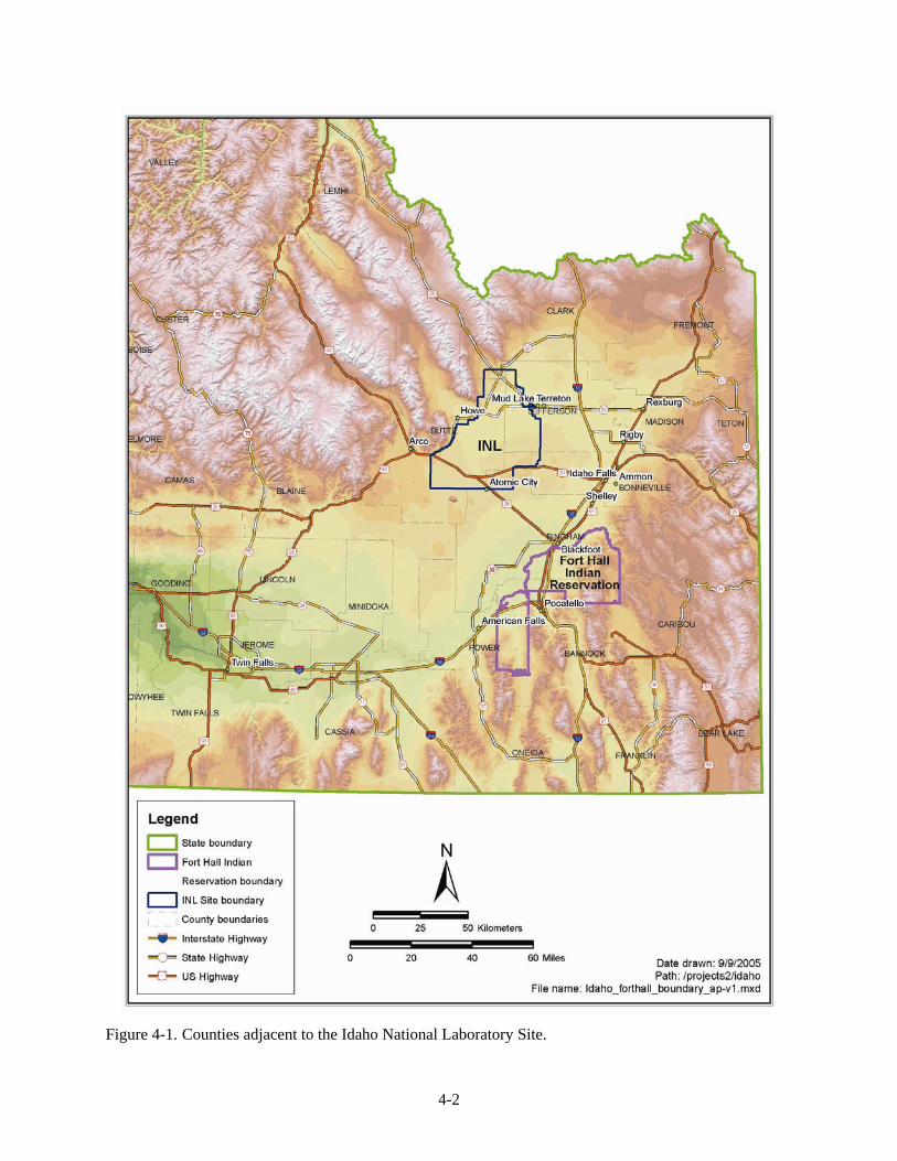
The INL Site is bordered by five Idaho counties: Bingham, Bonneville, Butte, Clark, and Jefferson (Figure 4-1). Major communities include Blackfoot and Shelley in Bingham County, Idaho Falls and Ammon in Bonneville County, Arco in Butte County, and Rigby in Jefferson County. Population estimates for the counties surrounding the INL Site and the largest population centers in these counties are shown in Table 4-1 (U.S. Census Bureau 2001, 2003). The community nearest to the INL Site is Atomic City, located south of the Site border on U.S. Highway 20/26. Other population centers near the INL Site include Arco, 11 km (7 mi) west of the INL Site; Howe, west of the INL Site on U.S. Highway 22/33; and Mud Lake and Terreton on the northeast border of the INL Site. There are no permanent residents at the INL Site (Hull 1989).
a. Personal communication between S. L. Ansley, CH2M-WG Idaho, LLC, and Scott Welch (Battelle Energy Alliance) and Lynette Martin, CH2M-WG Idaho, LLC), February 22, 2005.
4-2
Figure 4-1. Counties adjacent to the Idaho National Laboratory Site.
4-3
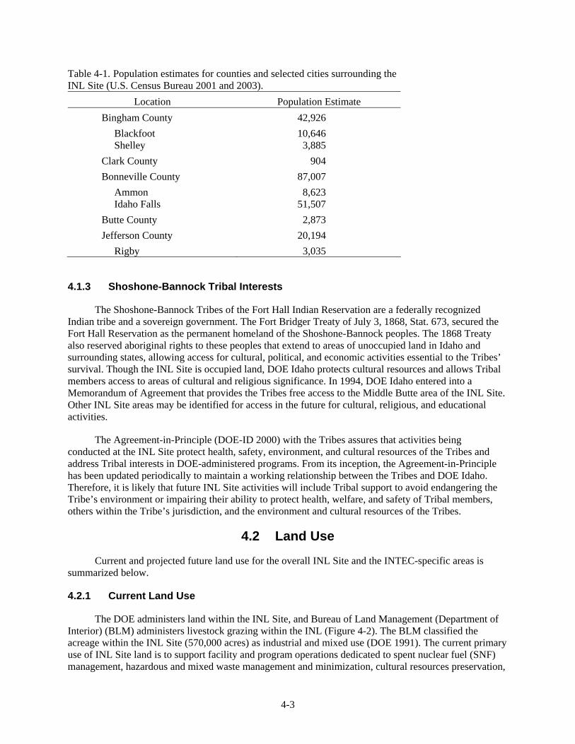
Table 4-1. Population estimates for counties and selected cities surrounding the INL Site (U.S. Census Bureau 2001 and 2003).
Location Population Estimate Bingham County 42,926 Blackfoot Shelley
10,646 3,885
Clark County 904 Bonneville County 87,007 Ammon Idaho Falls
8,623 51,507
Butte County 2,873 Jefferson County 20,194 Rigby 3,035
4.1.3 Shoshone-Bannock Tribal Interests
The Shoshone-Bannock Tribes of the Fort Hall Indian Reservation are a federally recognized Indian tribe and a sovereign government. The Fort Bridger Treaty of July 3, 1868, Stat. 673, secured the Fort Hall Reservation as the permanent homeland of the Shoshone-Bannock peoples. The 1868 Treaty also reserved aboriginal rights to these peoples that extend to areas of unoccupied land in Idaho and surrounding states, allowing access for cultural, political, and economic activities essential to the Tribes’ survival. Though the INL Site is occupied land, DOE Idaho protects cultural resources and allows Tribal members access to areas of cultural and religious significance. In 1994, DOE Idaho entered into a Memorandum of Agreement that provides the Tribes free access to the Middle Butte area of the INL Site. Other INL Site areas may be identified for access in the future for cultural, religious, and educational activities.
The Agreement-in-Principle (DOE-ID 2000) with the Tribes assures that activities being conducted at the INL Site protect health, safety, environment, and cultural resources of the Tribes and address Tribal interests in DOE-administered programs. From its inception, the Agreement-in-Principle has been updated periodically to maintain a working relationship between the Tribes and DOE Idaho. Therefore, it is likely that future INL Site activities will include Tribal support to avoid endangering the Tribe’s environment or impairing their ability to protect health, welfare, and safety of Tribal members, others within the Tribe’s jurisdiction, and the environment and cultural resources of the Tribes.
4.2 Land Use
Current and projected future land use for the overall INL Site and the INTEC-specific areas is summarized below.
4.2.1 Current Land Use
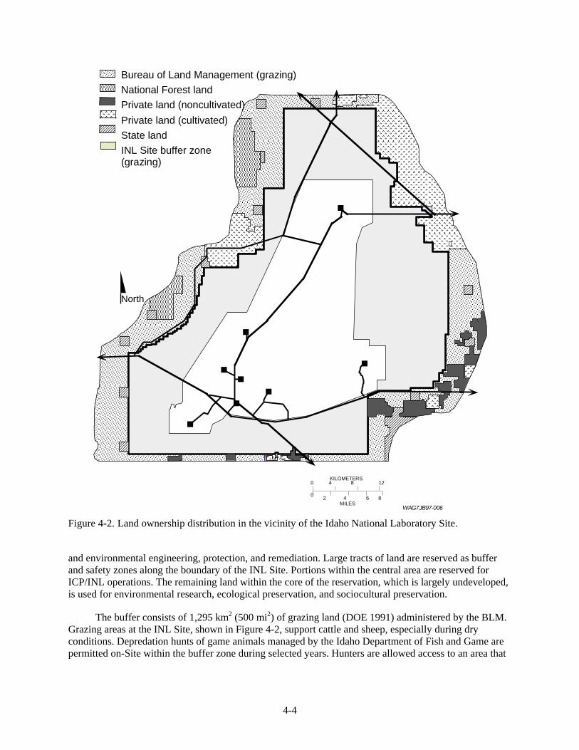
The DOE administers land within the INL Site, and Bureau of Land Management (Department of Interior) (BLM) administers livestock grazing within the INL (Figure 4-2). The BLM classified the acreage within the INL Site (570,000 acres) as industrial and mixed use (DOE 1991). The current primary use of INL Site land is to support facility and program operations dedicated to spent nuclear fuel (SNF) management, hazardous and mixed waste management and minimization, cultural resources preservation,
4-4
North
Bureau of Land Management (grazing)National Forest landPrivate land (noncultivated)Private land (cultivated)State landINL Site buffer zone (grazing)
0 2 4 6 8
0 4 8 12
MILES
KILOMETERS
W A G 7 J B 9 7 - 0 0 6 Figure 4-2. Land ownership distribution in the vicinity of the Idaho National Laboratory Site.
and environmental engineering, protection, and remediation. Large tracts of land are reserved as buffer and safety zones along the boundary of the INL Site. Portions within the central area are reserved for ICP/INL operations. The remaining land within the core of the reservation, which is largely undeveloped, is used for environmental research, ecological preservation, and sociocultural preservation.
The buffer consists of 1,295 km2 (500 mi2) of grazing land (DOE 1991) administered by the BLM. Grazing areas at the INL Site, shown in Figure 4-2, support cattle and sheep, especially during dry conditions. Depredation hunts of game animals managed by the Idaho Department of Fish and Game are permitted on-Site within the buffer zone during selected years. Hunters are allowed access to an area that
4-5
extends 0.8 km (0.5 mi) inside the INL Site boundary on portions of the northeastern and western borders of the Site (Becker et al. 1996).
State Highways 22, 28, and 33 cross the northeastern portion of the Site, and U.S. Highways 20 and 26 cross the southern portion (Figure 4-1). One hundred forty-five kilometers (90 mi) of paved highways used by the general public pass through the INL Site (DOE 1991), and 23 km (14 mi) of Union Pacific railroad tracks traverse the southern portion of the Site. A government-owned railroad, a spur of the Union Pacific railroad, passes through the CFA to INTEC and terminates at NRF.
In the counties surrounding the INL Site, approximately 45% of the land is used for agriculture, 45% is undeveloped land, and 10% is urban (DOE 1991). Livestock uses include the production of sheep, cattle, hogs, poultry, and dairy cattle (Bowman et al. 1984). The major crops produced on land surrounding the INL Site include wheat, alfalfa, barley, potatoes, oats, and corn. Sugar beets are grown within about 40 mi of the INL Site in the vicinity of Rockford, Idaho, southeast of the INL Site in central Bingham County (Table 4-2). Most of the land surrounding the INL Site is owned by private individuals or the U.S. Government.
4.2.2 Future Land Use
Future land use is addressed in the Long-Term Land Use Future Scenarios document (DOE-ID 1995), the Comprehensive Facility and Land Use Plan (INEEL 2003), and the Infrastructure Long-Range Plan (INEEL 2001). Because future land-use scenarios are uncertain, assumptions were made in the Long-Term Land Use Future Scenarios document for defining factors such as development pressure, advances in research and technology, and ownership patterns. The following assumptions were applied to develop forecasts for land use within the INL Site:
• The INL Site will remain under government ownership and control for at least the next 100 years. The boundary is currently static. (INEEL [2003] indicates that the boundaries of the INL Site may shrink.) Portions of the INL Site will be managed beyond 100 years under the long-term stewardship program.
• The life expectancy of current and new facilities is expected to range between 30 and 50 years. The decontamination and dismantlement process will commence following closure of each facility if new missions for the facility are not determined.
• No residential development (e.g., housing) will occur within the INL Site boundaries within 100 years.
• No new major, private developments (residential or nonresidential) are expected in areas adjacent to the INL Site.
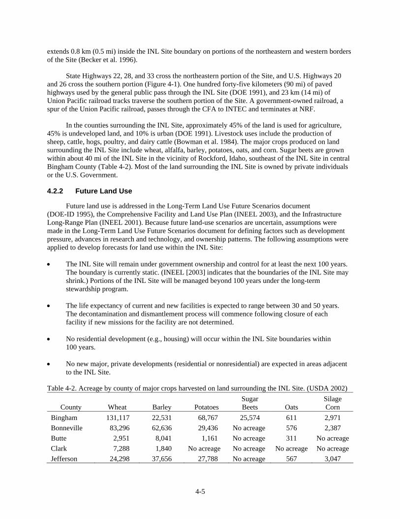
Table 4-2. Acreage by county of major crops harvested on land surrounding the INL Site. (USDA 2002)
County Wheat Barley Potatoes Sugar Beets Oats
Silage Corn
Bingham 131,117 22,531 68,767 25,574 611 2,971 Bonneville 83,296 62,636 29,436 No acreage 576 2,387 Butte 2,951 8,041 1,161 No acreage 311 No acreage Clark 7,288 1,840 No acreage No acreage No acreage No acreage Jefferson 24,298 37,656 27,788 No acreage 567 3,047
4-6
Future land use most likely will remain essentially the same as the current use: a research facility within the INL Site boundaries and agriculture and open land surrounding the INL Site. In addition, future land use will include the ICP/INL mission of nuclear energy research, development, and demonstration. Other potential but less likely land uses within the INL Site include agriculture and the return of the areas on-Site to their natural, undeveloped state.
Plans for future land use at the INL Site call for most of the developed areas of the Site to remain occupational for the 100-year planning period (to 2095). Included in the future land use plan for the INL Site is the assumption that new development will, to the extent practicable, be encouraged in developed facility areas to take advantage of existing infrastructure.
4.2.3 INTEC-Specific Current and Future Land Use
Current land use at INTEC is limited to industrial applications associated with (a) safe storage of SNF in preparation for shipment to a repository outside of Idaho, (b) technology development for safely treating high-level and liquid radioactive waste generated from previous fuel reprocessing activities, (c) remediation of past contamination releases to the environment, and (d) deactivation, decontamination, and decommissioning excess facilities. INTEC is a key part of implementing a 1995 settlement agreement whose key objectives are to remove all SNF from Idaho by 2035 and to prepare waste stored at the INL Site for removal from Idaho by the same date.
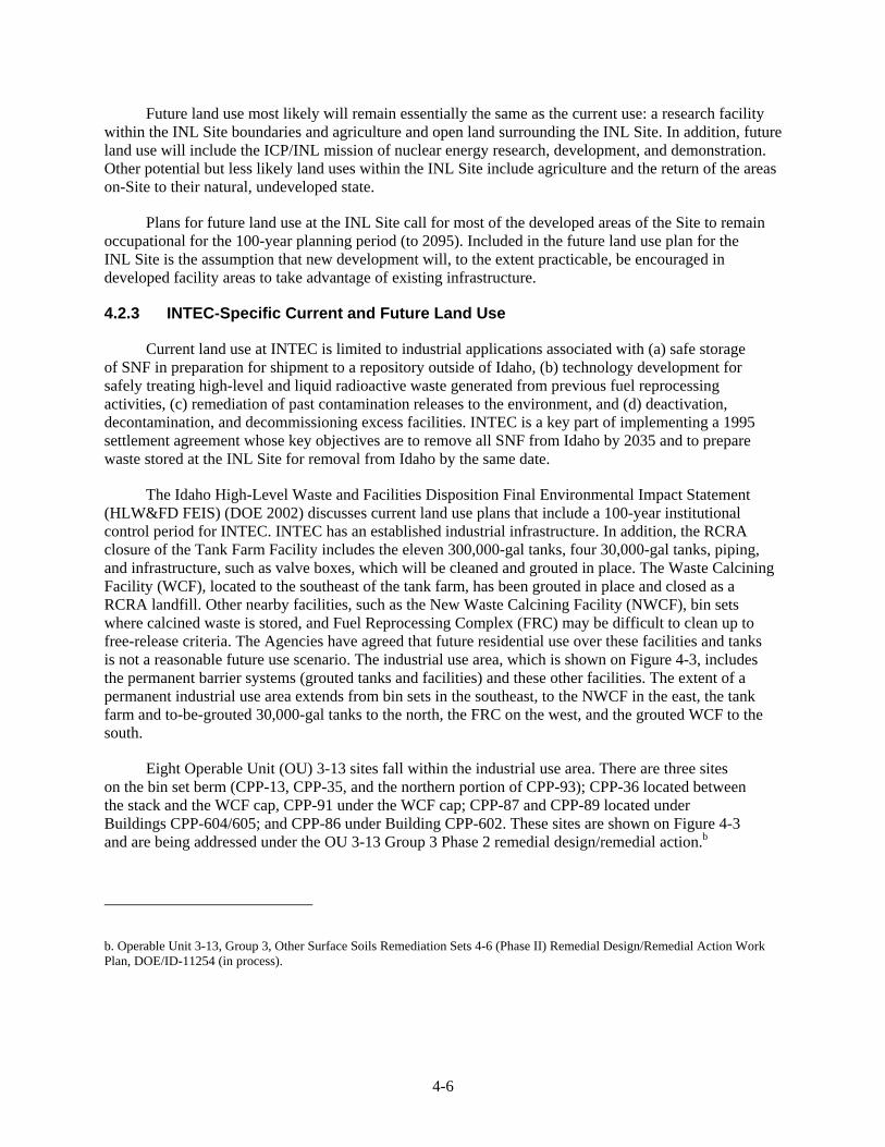
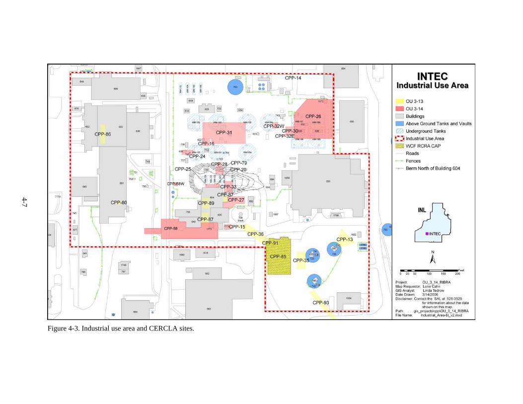
The Idaho High-Level Waste and Facilities Disposition Final Environmental Impact Statement (HLW&FD FEIS) (DOE 2002) discusses current land use plans that include a 100-year institutional control period for INTEC. INTEC has an established industrial infrastructure. In addition, the RCRA closure of the Tank Farm Facility includes the eleven 300,000-gal tanks, four 30,000-gal tanks, piping, and infrastructure, such as valve boxes, which will be cleaned and grouted in place. The Waste Calcining Facility (WCF), located to the southeast of the tank farm, has been grouted in place and closed as a RCRA landfill. Other nearby facilities, such as the New Waste Calcining Facility (NWCF), bin sets where calcined waste is stored, and Fuel Reprocessing Complex (FRC) may be difficult to clean up to free-release criteria. The Agencies have agreed that future residential use over these facilities and tanks is not a reasonable future use scenario. The industrial use area, which is shown on Figure 4-3, includes the permanent barrier systems (grouted tanks and facilities) and these other facilities. The extent of a permanent industrial use area extends from bin sets in the southeast, to the NWCF in the east, the tank farm and to-be-grouted 30,000-gal tanks to the north, the FRC on the west, and the grouted WCF to the south.
Eight Operable Unit (OU) 3-13 sites fall within the industrial use area. There are three sites on the bin set berm (CPP-13, CPP-35, and the northern portion of CPP-93); CPP-36 located between the stack and the WCF cap, CPP-91 under the WCF cap; CPP-87 and CPP-89 located under Buildings CPP-604/605; and CPP-86 under Building CPP-602. These sites are shown on Figure 4-3 and are being addressed under the OU 3-13 Group 3 Phase 2 remedial design/remedial action.b
b. Operable Unit 3-13, Group 3, Other Surface Soils Remediation Sets 4-6 (Phase II) Remedial Design/Remedial Action Work Plan, DOE/ID-11254 (in process).
4-7
Figure 4-3. Industrial use area and CERCLA sites.
4-8
In addition to limitations imposed by anticipated physical characteristics on future development, institutional controls will continue to be implemented at the INTEC facility for as long as land use or access restrictions are necessary to maintain protection of human health and the environment. The use of institutional controls has been established in the OU 3-13 Record of Decision (ROD) to prevent exposure to contaminated groundwater and soils until the risks reach acceptable levels.
Laws and regulations that govern the transfer of federal land are presented in the INEEL Sitewide Institutional Controls Plan (DOE-ID 2004a). These will ensure future protection of human health and the environment through required property transfer documentation (e.g., notices, zoning and deed restrictions, and covenants). Because INL Site land was withdrawn in 1949 from the BLM for the National Reactor Testing Station, the land will return to the BLM if no longer needed for the INL Site. An exception to this occurred when land in the northern part of the INL Site was given to Jefferson County for a landfill. Before the land was transferred, however, it was certified by the DOE and EPA to be uncontaminated. Contaminated land that may remain at INTEC will be under government control in perpetuity. Five-year reviews will also continue for sites where contamination has been left in place and is above levels that allow for unlimited use and unrestricted exposure. These reviews will continue until the Agencies determine that the sites no longer pose an unacceptable risk to human health and the environment and site access restrictions or use restrictions are no longer required.
4.3 Surface Features
Pertinent surface features at INTEC are described in Operable Unit 3-14 Tank Farm Soil and Groundwater Remedial Investigation/Feasibility Study Work Plan (DOE-ID 2004b), Phase I Monitoring Well and Tracer Study Report for Operable Unit 3-13, Group 4, Perched Water (DOE-ID 2003a), and the updated Comprehensive Facility and Land Use Plan. A significant surface feature change postdating the above publications are soil caps placed over the former site of the sewage treatment facility infiltration trenches (in the northeast corner of INTEC).
4.4 Geology
4.4.1 Regional Geology
The current state of knowledge of Eastern Snake River Plain (ESRP) and INL Site regional geology is discussed briefly below and summarized elsewhere (DOE-NE-ID 2004a and ICP 2005).
4.4.2 Subsurface Geology of the INTEC
The United States Geological Survey (USGS) and DOE have drilled and sampled the INTEC- and INEEL CERCLA Disposal Facility-area subsurface extensively in an effort to understand and monitor the movement of groundwater and contaminants. To date, over 120 wells have been drilled at and around INTEC. Approximately 47 of these wells were drilled to depths that penetrate into the Snake River Plain Aquifer (SRPA) (36 USGS monitoring wells, four production wells, and seven INTEC monitoring wells); approximately 73 of the wells are completed in the vadose zone to monitor the various perched water bodies beneath INTEC; and numerous holes have been drilled at INTEC in the surficial sediments to the top of the basalt.
4.4.2.1 Basalt Flow Structure. The term “basalt flow” is used somewhat loosely in the context of ESRP geology to describe individual flows, groups of flows, or flow subsets. In some cases, a basalt flow may refer to a flow group, which is a group of petrographically similar flows that erupted from the same magma chamber (Anderson and Lewis 1989). In other cases, a flow will refer to a separate distinct lobe that issued out from a parent flow. Volcanism in the ESRP has been episodic, emplacing lava flows
4-9
over relatively short periods (a few hundred to a few thousand years), with long periods of volcanic quiescence (tens of thousands to millions of years). During the quiescent periods, loess, alluvial silt, sand, gravel, and lacustrine clays and silt are deposited on top of the basalt, often in topographic lows.
Two types of basalt flows are commonly erupted on the ESRP: (1) a form known as pahoehoe, which is a low-viscosity lava that produces thin tongues and lobes, and (2) aa, which is a high-viscosity lava that results in blocky angular flows. A third “hybrid” type of basalt is also found among the lava flows of the ESRP. Malde (1991) suggests that this hybrid basalt was formed by magma interacting with crustal rocks at depths of about 19 mi. As suggested by Greeley (1982), pahoehoe is the dominant type of basalt that erupted along volcanic rift zones on the Snake River Plain and forms the long, low-angle flanks of the low shield volcanoes typical of plains-style volcanism. The shields form in an overlapping manner, with minor fissure-fed flows often filling in low areas between shields, producing a subdued topography.
A typical basalt flow can be divided into four layered elements (Knutson et al. 1990). The lowest layer is the substratum, consisting of a ropy pahoehoe surface, fracture and fissured surfaces, and rubble zones (see Figure 2-2 of Knutson et al. 1990). This layer accounts for about 5% of the flow thickness. Above the substratum is a lower vesicular zone that contributes an average of 11% of the flow thickness. Vesicles form by degassing of the lava, and polygonal fracturing is common in this layer. The massive central element, or nonvesicular zone, of the flow composes about 49% of the thickness. The central element is dense, with few fractures except for vertical columnar jointing. The uppermost element of the flow is the upper vesicular element, accounting for about 35% of the thickness of the flow. This element may have a parting parallel to the upper surface as well as fissures and broken basalt.
The saturated hydraulic properties of basalt are very anisotropic. The most important portions of the basalt flow contributing to the horizontal transmission of water for saturated conditions are the rubble zones between basalt flows in which the lower rubble zone from one flow lies on top of the upper vesicular element of the flow beneath it. Layered basalt flows, therefore, have a high horizontal saturated permeability.
Fractures in subsurface basalt lava flows commonly contain fine-grained sediment infilling and fracture wall coatings because of downward percolation from the overlying sediments. The sediment infilling of the fractures should cause a decrease in the permeability of fractured basalt below the interbeds, though the effects of sediment infilling have not been measured. Where the top of a flow has been covered and fractures have been filled with fine-grained sediment, a low-permeability layer can form. The massive central element of a flow can also have very low permeability, depending on the extent of fracturing.
4.4.2.2 Distinct Stratigraphic Marker Units at INTEC. A detailed study of borehole data from the INTEC wells was completed during the preparation of the OU 3-13, Group 4, Monitoring Well and Tracer Study Report (DOE-ID 2003a). The study included the evaluation of available basalt/interbed core samples; geochemical, paleomagnetic, and K-Ar age dates; and petrographic data. Results of the study indicated that several distinct units exist beneath INTEC that can be used as marker units. The marker units included the following:
• Surficial alluvium—exists across the INTEC facility with the contact at the first basalt easily identified.
• Upper basalt flows—the number of basalt flows between 30 and 115 ft below ground surface (bgs) ranges from one to four flow units. Up to four units exist beneath the northern portion of INTEC, and a single flow unit exists beneath the southern portion of INTEC. Paleomagnetic data for one
4-10
of the flows at 100 to 115 ft bgs showed significantly higher inclinations than others in the group, which could potentially be used to better map the flow as new data become available.
• 110-ft interbed—generally encountered between 100 to 120 ft bgs and ranges from 0 to 25 ft thick. This interbed is an important marker unit due to its presence in nearly all of the wells that penetrate deep enough to encounter the unit. The thickest portions of the unit rest under the northeast corner of INTEC. The 110-ft interbed is not present at the tank farm well set in the northern portion of INTEC.
• High K2O basalt flow—characterized by a high natural gamma count due to higher potassium content. The flow is found between 110 and 150 ft bgs and is absent from the east and southeast extremes of INTEC. When the high K2O flow is encountered, it lies stratigraphically below the 110-ft interbed.
• 140-ft interbed—typically encountered between 140 and 150 ft bgs. This interbed does not appear to be as continuous as the 110-ft interbed, which may be due in part to a lack of data.
• Middle massive basalt—one of the thickest, most massive basalt flows found in the vadose zone beneath INTEC. Typical thickness for this unit is around 100 ft. The base of the unit appears to be relatively flat-lying, while the upper surface has a south to southwest slope. This unit is encountered between approximately 220 and 280 ft bgs.
• 380-ft interbed—a relatively continuous flat-lying layer that varies in thickness from 6 to 27 ft. Depth to the interbed ranges from 320 to 420 ft bgs. This interbed appears to be continuous and relatively thick beneath the INTEC tank farm and thins to the south.
• Low K2O basalt flow—identified in Wells USGS-121 and -123 and was found to have a low K2O content, based on geochemical sampling results. As a result of the low K content, this flow displays abnormally low natural gamma radiation. The basalt flow was found at 415 ft bgs in both wells. A similar reading from basalt was found at 384 ft bgs in Well ICPP-COR-A-023.
4.4.2.3 Recent and Continuing Stratigraphic Interpretations of the INTEC Area. Stratigraphic cross-sections through the INTEC facility presented in the Phase I Monitoring Well and Tracer Study Report (DOE-ID 2003a) are the most recent, detailed analyses of INTEC-specific shallow (less than 500 ft bls) geology. These diagrams, prepared using the best information available at the time, were based primarily on shape-matching natural gamma response logs from boreholes across the INTEC area, augmented by paleomagnetic measurements (from deep wells USGS-121, USGS-123, and ICPP-COR-A-023); geochemical measurements (also from deep wells USGS-121, USGS-123, and ICPP-COR-A-023); and K-Ar age dating measurements (from USGS-121 and USGS-123).
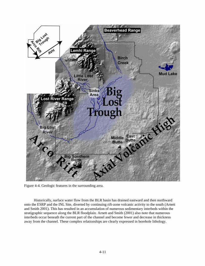
The INTEC facility is located on the edge of the current surface expression of the Big Lost River (BLR) flood plain. On a larger scale, the facility lies within the Big Lost Trough, a low-relief area covered with a veneer of sediments, and includes the BLR and Little Lost River floodplain and sinks (Figure 4-4). The Big Lost Trough is bounded on the south/southeast by the Axial Volcanic High and by the Big Lost, Lemhi, and Beaverhead ranges to the west and northwest. Its shape and length are dominated by the length of the BLR on the ESRP. This location is important to understanding the stratigraphic relationships beneath INTEC because it has controlled the entire pattern of drainage and deposition of basalt and sedimentary material along the Big Lost Trough. Specifically, the result has been an extensive interfingering of basalt units and sedimentary materials along the axis of the Big Lost Trough, which roughly parallels the current channel of the BLR. Kuntz et al. (1994) suggested that the flow direction of most basalts in the Big Lost Trough has been away from the topographically high areas and toward the BLR.
4-11
Figure 4-4. Geologic features in the surrounding area.
Historically, surface water flow from the BLR basin has drained eastward and then northward onto the ESRP and the INL Site, diverted by continuing rift-zone volcanic activity to the south (Arnett and Smith 2001). This has resulted in an accumulation of numerous sedimentary interbeds within the stratigraphic sequence along the BLR floodplain. Arnett and Smith (2001) also note that numerous interbeds occur beneath the current part of the channel and become fewer and decrease in thickness away from the channel. These complex relationships are clearly expressed in borehole lithology.