Embed Size (px)
Citation preview
Figure Control of Lightweight Optical Structures
NCC-1-385
John A. Main, Principal Investigator Haiping Song, Postdoctoral Research Associate
Department of Mechanical Engineering University of Kentucky
Lexington, KY 40506-0503
Abstract
The goal of this paper is to demonstrate the use of fuzzy logic controllers in
modifying the figure of a piezoceramic bimorph mirror. Non-contact electron actuation
technology is used to actively control a bimorph mirror comprised two PZT-5H wafers by
varying the electron flux and electron voltages. Due to electron blooming generated by
the electron flux, it is difficult to develop an accurate control model for the bimorph
mirror through theoretical analysis alone. The non-contact shape control system with
electron flux blooming can be approximately described with a heuristic model based on
experimental data. Two fuzzy logic feedback controllers are developed to control the
shape of the bimorph mirror according to heuristic fuzzy inference rules generated from
previous experimental results. Validation of the proposed fuzzy logic controllers is also
discussed.
Keywords: Bimorph mirror, Electron gun, Fuzzy logic controller
1. Introduction
1 1
https://ntrs.nasa.gov/search.jsp?R=20050169240 2018-08-14T20:26:09+00:00Z
Piezoelectric actuators have been used for shape control since the earliest
development of adaptive mirrors. In 1974, a monolithic piezoelectric mirror was
designed using piezoelectric ceramic stacks to induce a deformation on a the mirror
surface[']. Steinhaus et. aI[*] investigated a piezoelectric flexible mirror with multiple
electrodes to control numerous discrete areas. This consisted of a bonded layer of
piezoceramic on the back of a thin glass mirror; a continuous electrode was located at
the interface and an array of twelve electrodes was distributed on the back of mirror.
Microelectronic techniques were used to build a segmented bimorph deformable mirror
using low-voltage bending PZT bimorph wafers[31. Another bimorph design used PZT
with a continuously grounded electrode between the layers deposited on either side of
the bimorph". Other composite deformable mirrors 1516] were developed by embedding
multiple piezoelectric actuator patches in the laminates during fabrication. These
implementations require a complex power supply with multiple channels and a
corresponding controller to control multiple electrodes dynamically. In addition, the size
and placement of actuator patches could not be adjusted after the mirror was
manufactured.
To simplify the mirror structure and control system, a non-contact technique for
deformable mirror control using an electron gun control has recently been proposed m.
The authors have developed a bimorph mirror that consists of two PZT-5H wafers 50.8
mm in diameter, Imm thick, and cemented together with RTV-11 glue. One surface is
polished and has deposited on it a reflective aluminum surface. Of course, the obvious
advantages of this system is that the mirror structure is much less complex than
2 2
adaptive mirrors using conventional actuators and the addressable areas in the mirror
are not defined by the system hardware.
Hubbard [*I initially considered use of electron gun actuation for control of
deformable mirrors. In this case the mirror was constructed from a PVDF bimorph.
Main and Nelson [9i101 demonstrated that the strain in piezoelectric materials could be
controlled through a combination of applied electron beams and control voltage to the
opposite surface. This approach was similarly used to control the shape of membrane
mirrors [I1]. An improved electron gun actuation method was proposed by placement of
a screen collector near to the PZT surface[']. Results indicated that the method is
capable of producing positive and negative deformation of a mirror in a very short time.
Since the electron accumulation on PZT material may remain relatively static even after
the removal of the electron beam, the electron gun control method has the ability to
actuate distributed points simultaneously similar to multiple electrodes attached to the
mirror.
Significant advantages of non-contact electron gun control include a simplified
mirror structure as well as high spatial and temporal resolution in the excitation areas.
Nevertheless, the collision dynamics of the electron with the surface of a PZT material is
complex due to the nature of the energy transfer, secondary electron yield and
absorbed electron blooming['*]. Therefore, the deflection response of a bimorph mirror
using electron flux excitation cannot be expressed precisely even though an analysis
tool (for example, ANSYS@), can be used to simulate the electromechanical coupling
behavior of the PZT bimorph. The control method discussed in this paper is an
3 3

uncertain system, which can be approximately described with the heuristic variables
according io previous experimental results.
Fuzzy logic control (FLC) is advantageous for nonlinear or uncertain systems[‘31.
An obvious advantage of FLC techniques is the synthesis of human knowledge and
expertise in dealing with uncertainties in the control phase. Fuzzy logic control usually
decomposes a complex system into several local systems according to the expert’s
understanding of the subsystem and uses a simple control law to emulate the expert’s
control strategy in performing certain control tasks. Fuzzy systems provide a general
methodology for representing the complexity of real world problems. FLC algorithms will
be applied herein to correct the shape of a bimorph mirror with a non-contact closed
loop control system. The excitation of electron flux and two controllable voltages on the
surface of the mirror and on the screen collector, respectively, will be used as actuation
inputs. A wavefront sensor will be utilized to measure the mirror profile to provide shape
feedback.
2.
2.1 Experimental setup
Experimental setup and feedback control system
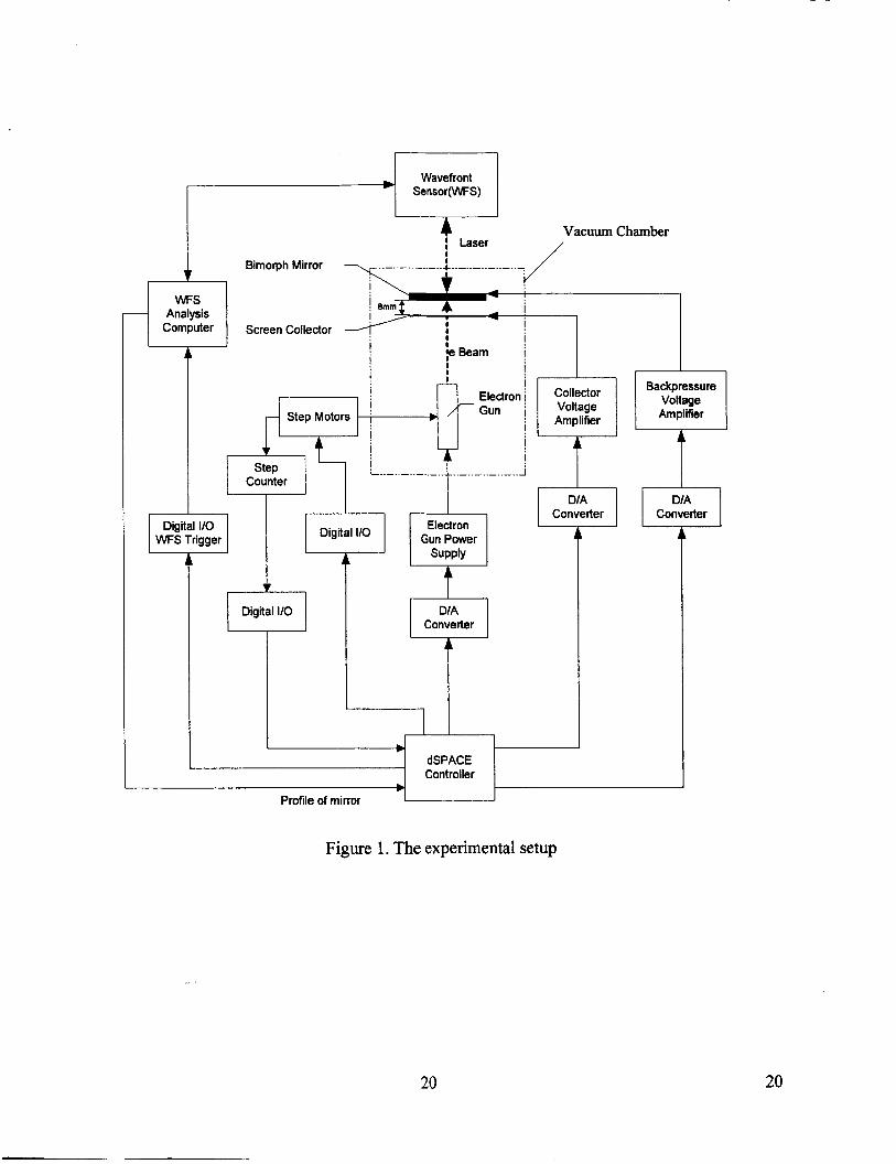
The experimental setup, as shown in Figure 1, consists of a bimorph mirror, an
electron gun system, two voltage control amplifiers, a wavefront sensing light
measurement system, a dSPACE controller system and a vacuum chamber. The
bimorph mirror is a composite layer structure consisting of a PZT bimorph mounted on a
self-centering jaw clamp with three constraint points. The electron gun system includes
an electron gun, a power supply and a localizer. The electron gun is a Kimball Physics
4 4
EFG-7. The electron gun power supply is used to adjust electron beam energy, focus
the beam, and switch the beam on or off, while the iocalizer is used to control shooting
points on the mirror. The voltage control amplifiers are used to supply the backpressure
voltage on the surface of the mirror and the collector. The dSPACE controller system
consists of a PC with an interface unit consisting of multi-channel D/A and digital I/O
ports.
Since the electron gun can only be operated in a vacuum environment
(approximately I 0-5 Torr minimum), the mirror, electron gun and screen electron
collector are mounted in the chamber. The wavefront sensor (Wavefront Sciences
CLAS-2D) measures the modal deformation through a window in the chamber; the
corresponding deformation information of the mirror is fed into the dSPACE control
computer. The dSPACE controller calculates the magnitudes of controllable variables
applied to relevant voltage amplifiers and to the electron gun system.
The wavefront system is a Shack-Hartmann sensor in which the Zernike polynomials
(shown in Equation I) are implemented using modal reconstruction to recreate the
phase + ( x , y ) . The order of the polynomial fit that describes the surface will directly
affect both the processing time and the visibility of higher order terms. For acquiring a
phase of the mirror in appropriate computing time for the closed loop control, a fourth
order polynomial is used, as it is generally an adequate option for most tests [l4]. The
phase +(x ,y) is given by
5 5

where znk (x ,y) is the kth Zernike polynomial of nth order and unk refers to the coefficient
Of znk ('9Y) *
In the dSPACE control computer, a Matlab simulink program was converted into
real-time code that is utilized to operate dSPACE's digital I/O board and AID-D/A board
to control the electron gun parameters. Moreover, the Matlab-dSPACE interface has the
ability to control an experiment via a Matlab script.
2.2 Selection of input and output variables
The controllers explored in the current effort are used to modify the shape of a
bimorph mirror to a desired profile. The wavefront sensor is used to measure the mirror
profile and feedback this to the controller. Thus, the error between measured profile and
desired profile can be defined as input variables.
The goal of shape control process can be represented as
e , (k) = w(k)-wd 0 (2)
where wd is a desired deflection matrix of a bimorph mirror, and w(k) and e , (k)
represent a measured deflection matrix and corresponding error matrix, respectively.
Since the deflection of the mirror's profile measured by the WFS is always
positive, a transformation of the error matrix can be performed through the computation
of average error on the mirror such as
- e m = e , (k>-avg(e , (W (3)
Then, the maximum and minimum values in &(k) and their coordinates can be
obtained by the following formulae.
6 6

wf (k) = min f, (k)) (4)
Obviously, w;(k) is positive and wf(k) is negative. Their corresponding positions on the
profile of the wavefront sensor can be conveniently derived from the wavefront phase
matrix. Therefore, the maximum and minimum errors of deflections on the mirror can be
defined as points of excitation for an electron flux and thus are also input variables for
the controller. Note that actuating points on the mirror are variable when using the
noncontact electron gun control method.
Due to the influence of boundary constraints on the mirror, different areas on the
mirror actuated with the same values of input control variables can produce different
mirror deformations. A finite element model for this kind of bimorph mirror has been
constructed in ANSYS 5.7 to calculate the deformation of the mirror. The bimorph mirror
structure has been modeled by SOLID5 elements with a 6 node 3-D coupled-field brick
element with piezoelectric and structural field capability. The back of the mirror model is
excited at 100 volts at a point lmm in diameter, with the corresponding ground
simultaneously connected to the mirror surface. It is assumed that the polarization in the
PZT-5H sheet is uniform and perpendicular to the surface of the mirror and anti-parallel
in successive layers. The piezoelectric and mechanical properties of PZT-5H are
summarized in Table 1, in which CJ are the elastic stiffness constants, e4 the
1 2
piezoelectric constants and q the dielectric constants. It is noted that C,= -(Cll-C12).
Exciting nine different points on the back of mirror, as shown in Figure 2, makes use of
the finite element model to analysis out-of-plane deformations of the bimorph mirror
according to the no blooming assumption of the electrode in a PZT-5H sheet. An
7 7

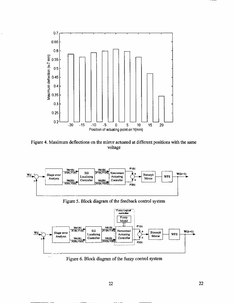
analytical result of the bimorph mirror is shown in Figure 3 and the maximum deflections
on nine different spots are shown in Figure 4. Results illustrate that the mare distant the
excitation spot is from the constraint points, the larger the deformation of the mirror at
the same input voltage. Thus, the position of the actuating point can be considered as
an input variable.
Output variables should include the position of actuation points, electron gun
operating parameters, and control voltages. The position of the actuation points can be
directly delivered to the localization system of the electron gun. Though there are many
variables used to control the electron gun (for example, energy level, focusing area,
source and grid voltages, etc.), only electron gun energy (V,) was used as a control
variable to simplify the controller output as well as following the results of previous
experiments. Other parameters of the electron gun can be set to invariants or functions
of energy; for the experiment discussed herein, the source voltage is equal to 1.4 VI
focus/energy is 0.65 on the Kimball Physics EFG-7 in order to produce a minimum
beam point on the object, and the grid voltage (V,) is used to turn on or off the electron
beam current. As the grid voltage is increased, the cathode emission is suppressed and
eventually completely cut off. The grid voltage is expressed by an empirical formula
obtained by measuring the emission current while adjusting grid voltage.
0.062 x (V, - 500) + 15 if V' > 400 if V, 1400 v' = {*.*o
The shooting time of the electron flux (T,) is also an important adjustable parameter that
can be determined by altering grid voltage.
8 8

In summary, the control variables in this system are the backpressure voltage
( V b ) on the mirror surface, the collector voltage ( Vc j on the screen collector, the energy
voltage (V , ) of the electron gun as well as the shooting time (T,) of the electron flux.
Based on these definitions of input and output variables, Figure 5 shows a block
diagram of the discrete feedback control system for the control of a bimorph mirror, in
which two points are excited in each control loop.
3. Fuzzy logic control with discrete feedback
Fuzzy logic control utilizes knowledge of process control based on human
perspective and experience. Thus, the designer is required to have sufficient knowledge
of how the mechanism of the system functionally operates, plus a good idea of how the
control system should behave. The actuating mechanism of the non-contact control
discussed herein is inherently more complicated than a conventional actuator. The
actuator is dependent on the electron flux that is induced by a provided energy voltage,
source voltage, focus voltage, and the shooting time. In addition, both backpressure and
collector voltages are important parameters to in deformation characteristics. Therefore,
this can be classified as an uncertain system that cannot be described with an
approximated mathematical relationship. However, this system can be represented with
some simple heuristic expressions. Thus, we use a fuzzy logic scheme for shape
control of the bimorph mirror system.
In designing a fuzzy logic controller, one must be able to identify control variables
(i.e., heuristic parameters) in order to describe inputs and outputs of the fuzzy system.
The heuristic quantification is used to create a set of rules that contain the control
9 9

process rules. In this section, fuzzy inference algorithms using single-input/muIti-output
(SIMO) and multi-input/multi-output (MIMO) schemes for each excitation point on the
surface of PZT-5H sheet are developed in order to control the mirror shape effectively.
The fuzzy control system is shown in Figure 6.
3.1 SIMO fuzzy logic control
One can see from Figure 5 that there are two excitation points in every control
loop. At first, we consider the deflection error on each excitation point as a single input
variable of the non-contact-actuating controller. In this control procedure, the
backpressure voltage ( Vb) , the collector voltage ( V , ) , the electron gun energy voltage
( V , ) and its shooting time ( T , ) are defined as the output variables. For construction of a
simple fuzzy inference model for a non-contact-actuating controller, we consider
maximum or minimum deflection error (wL(k),wf(k)) as three heuristic items; i.e., (WN,
WZ, WP}, where WN is a negative deflection error, WZ is a zero deflection error and
WP is a positive deflection error. Their membership functions, shown in Figure 7, were
defined as Z-, triangular- and S-shaped curves, respectively.
Based on previous experimental results[71, four output control variables can be
determined from their rational heuristic variables. Three heuristic terms, Le. {BN, BZ,
BP}, are used to define the backpressure voltage (Vb(k) ) . These items consist of Z-
shaped, triangular and S-shaped membership functions in which BN, BZ and BP
express negative, zero and positive backpressure voltages respectively. Additionally,
three other output variables are always defined in the positive numerical range. We
define the screen collector voltage (V, (k) ) , the electron flux energy (Ye (k ) ) and the
10 10
electron flux shooting time (T‘(k)) as fuzzy heuristic items {CS, CL}, {ES, EM, EL} and
{TS, TL}, where, IC’, ‘E’ and ‘T’ represent the collector voltage, the electron energy and
the actuation time, respectively. Here, ‘SI, ‘M’ and ‘L’ represent small, middle and large
values, respectively. Their membership functions shown in Figure 8 are summarized
from a number of previous experimental results.
The fuzzy logic rule base is usually in the form of IF-THEN rules that are derived
from experimental results on how to control the plant in order to effectively link the input
and output variables. The establishment of these rule bases depends heavily on the
designer’s experience, knowledge about the plant, analysis and design skill, etc. For the
shape control of the bimorph mirror, two general rules are composed as follows:
IF error is positive, THEN actuating force is negative IF error is negative, THEN actuating force is positive (6)
This means that a negative actuating force is used to deform the mirror to decrease the
error of deflection on the mirror when the error is positive. The reverse is also true. In
the non-contact shape control system, the actuating force is roughly decided by four
controllable parameters; V,, V, ,Ve andre. Hence, the fuzzy logic controller based on rule
base in Equation 6 should be a single-input and multi-output system and a fuzzy
inference mechanism must be constructed to obtain the four output variables from
single input variable. Three rules applied to the shape control of the bimorph mirror are
constructed as follows:
Rulel: IF w,(k) is ‘w”
THEN Vb(k) is ‘BPI and Vc(k) is ‘CS’ and Ve(k) is ‘EL’ and T‘(k) is ‘TS’ ,. .
Rule2: IF w,(k) is ‘WP’
11 11
THEN V,(k) is ‘BN’ and V,(k) is ‘CL‘ and V,(k) is ‘EM’ and T,(k) is ‘TL’ (7)
Rule3: IF w,(k) is ‘W’
THEN V,(k) is ‘BZ and V,(k) is ‘CS‘ and V,(k) is ‘ES’ and T,(k) is ‘TS’
The inference mechanism is divided into two subsections. The first operation is the
determination of the applicability of each rule according to the fuuification of w, ( k )
represented with a membership function shown in Figure 7. Since the input value is very
large in a positive direction and very small in a negative direction, the value of the input
membership function might be defined as 1. The second step in the inference section is
to obtain the output variables from the rules. Once the condition of deflection error has
been determined, the output variables can be calculated by the inverse computation of
their corresponding membership functions according to the fuzzy rules. For example, if
w,(k) is a negative value (O<w,(k)<-l), its membership function value ( p w ( k ) ) can be
computed with a Z-shaped curve membership function and the output variable ( Vb(k)) is
positive (BP) as given from rulel. It is assumed that
pb (k ) = pw ( k ) (8)
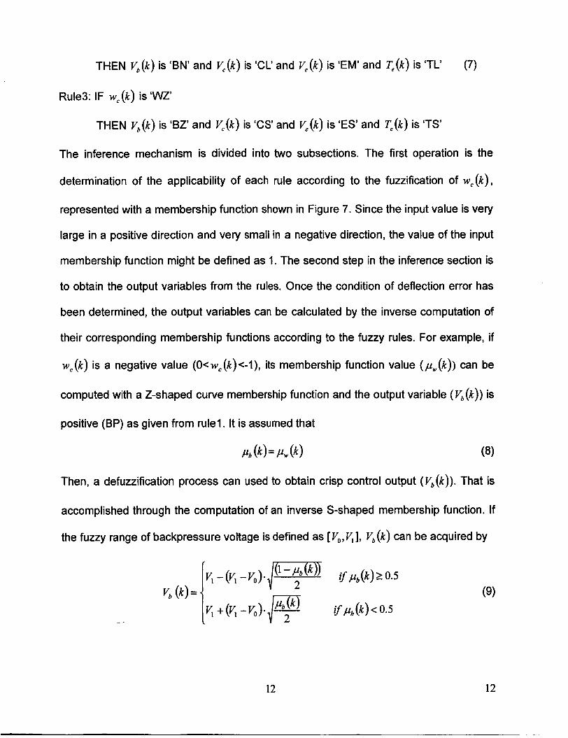
Then, a defuzzification process can used to obtain crisp control output (V,(k)) . That is
accomplished through the computation of an inverse S-shaped membership function. If
the fuzzy range of backpressure voltage is defined as [ VO,V,], V,(k) can be acquired by
.. .
12 12
The crisp values of other control variables can be acquired in the same way by
considering the inverse function of their corresponding membership functions. The main
purpose of defuzzification is to convert the result of fuzzy inference into a crisp result for
the implementation of the control process.
3.2 MlMO fuzzy logic control
Analytical results from finite element analyses represent that deformations of the
mirror actuated with the same controllable variables are different for different excitation
points. The maximum deflections on the mirror also depend on the distance between
the excitation point and constraint points. It is obvious that a greater deformation is
achieved when the excitation point is further from the constraint points. Thus, a MlMO
fuzzy logic controller for the system can be established by taking into consideration the
deflection error and position of the excitation point as two input variables, and four
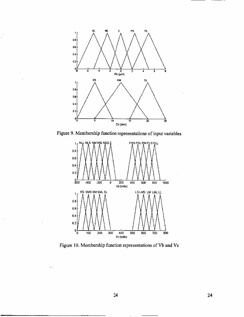
adjustable parameters ( Vb , V, , V, and T, ) as four output variables. Five triangular
membership functions for the deflection heuristic terms are given in Figure 9,
{NL,NS,Z,PS,PL}. The fuzzy expression of the excitation point position ( D, ) is
comprised of three heuristic terms, {DS,DM,DL}, and is shown in Figure 9. D,is a
minimum distance expressed by
D, = min(D,, D2, D3)
where D, , D2 andD, are the distance values from the excitation point to the three
constraint points.
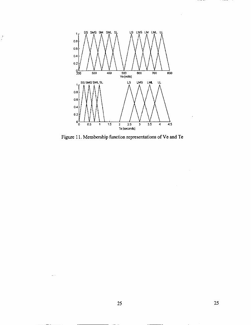
For the four output variables, membership functions using triangular functions are
represented in Figures 10 and 11 in terms of previous experimental and analytical
13 13
results, where adjustable voltages Vb and V, are described by eleven and ten heuristic
terms, respectively, and the electron flux parameters V, and Teare defined by ten and
eight heuristic terms, respectively. Accordingly, this MlMO fuzzy model for the shape
control of the bimorph mirror can be expressed by a Mamdani fuzzy model['31. The rule
base of this fuzzy model shown in Table 2 consists of 15 rules for each output variable,
adopted from all possible combinations of the antecedent terms.
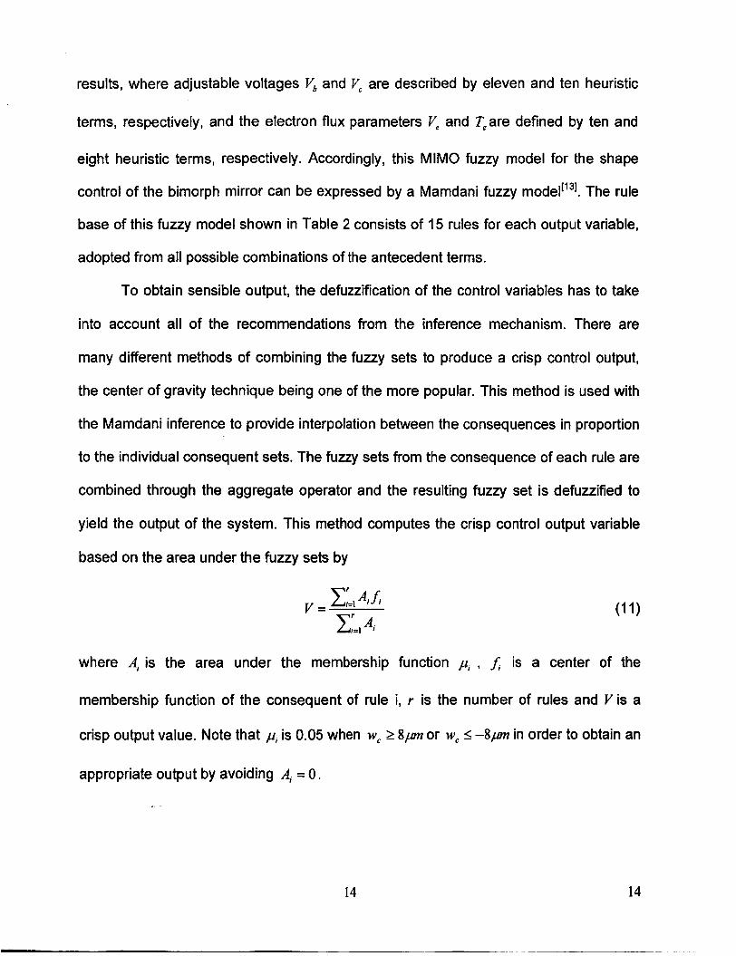
To obtain sensible output, the defuzzification of the control variables has to take
into account all of the recommendations from the inference mechanism. There are
many different methods of combining the fuzzy sets to produce a crisp control output,
the center of gravity technique being one of the more popular. This method is used with
the Mamdani inference to provide interpolation between the consequences in proportion
to the individual consequent sets. The fuzzy sets from the consequence of each rule are
combined through the aggregate operator and the resulting fuzzy set is defuuified to
yield the output of the system. This method computes the crisp control output variable
based on the area under the fuzzy sets by
where A, is the area under the membership
membership function of the consequent of rule
function p, , f , is a center of the
i, r is the number of rules and Vis a
crisp output value. Note that p, is 0.05 when W, 2 8,um or W, I -8,um in order to obtain an
appropriate output by avoiding Ai = 0.
,. .
14 14

4. Experimental results and discussion
The aim of bimorph mirror shape control is to reduce the error of the bimorph
mirror shape between the measured and desired shape by adjusting the out-of-plane
deformations of the mirror with non-contact electron gun excitation through the
presented control method, which is either a feedback control with SlMO or MlMO fuzzy
logic control according to the observations from the wavefront sensor. The controlling
goal can be defined as
Min J ( k ) = w: (k) - w,' (k) (1 1)
where J ( k ) is a control aim value and k expresses the kth discrete control loop.
The excitation points of the electron gun can be distributed to any possible position
on the back of the mirror. To obtain the excitation points, a map is created from the
measurement profile of the mirror to the real mirror geometry. Using Equations (3) and
(4), we can determine two actuation points directly from the maximum and minimum
error displacement points on the mirror in each control loop. However, these points
could possibly be on the edge of a profile. As the shooting points of the electron gun are
derived directly from the wavefront profile, these points might also be on the edge of the
mirror structure that could be difficult for the electron flux to properly target. To avoid
this problem, the location of the excitation points are determined by calculating the
weighted average of the region nearest to the position of the maximum or minimum
deflection with a 0.8 threshold value of the corresponding peak value.
Based on the assumption that the desired shape of the mirror is nearly flat, two
experiments have been implemented by using the two types of FLC controllers
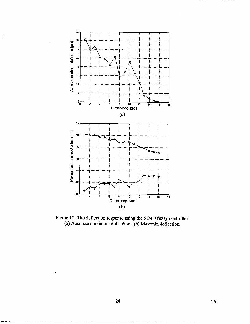
proposed in section 3, respectively. Figure 12a and 12b show the response of absolute
15 15

maximum deflection and max-min deflections on the mirror, respectively, with respect
for the SIMO fuzzy controller. The absolute maximum deflection can be reduced from
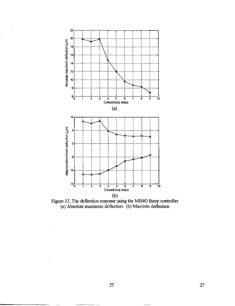
24.27 pm to 10.12 pm in sixteen control loops. Figure 13a and 13b show the deflection
response of the absolute maximum and max-min errors, respectively, using the MlMO
fuzzy controller. The absolute maximum deflection has been decreased from 19.85 pm
to 6.91 pm in nine control loops. Though both control methods can effectively reduce
the deformation of the bimorph mirror in several control steps, the MlMO fuzzy controller
has a more efficient solution than the SlMO fuzzy controller.
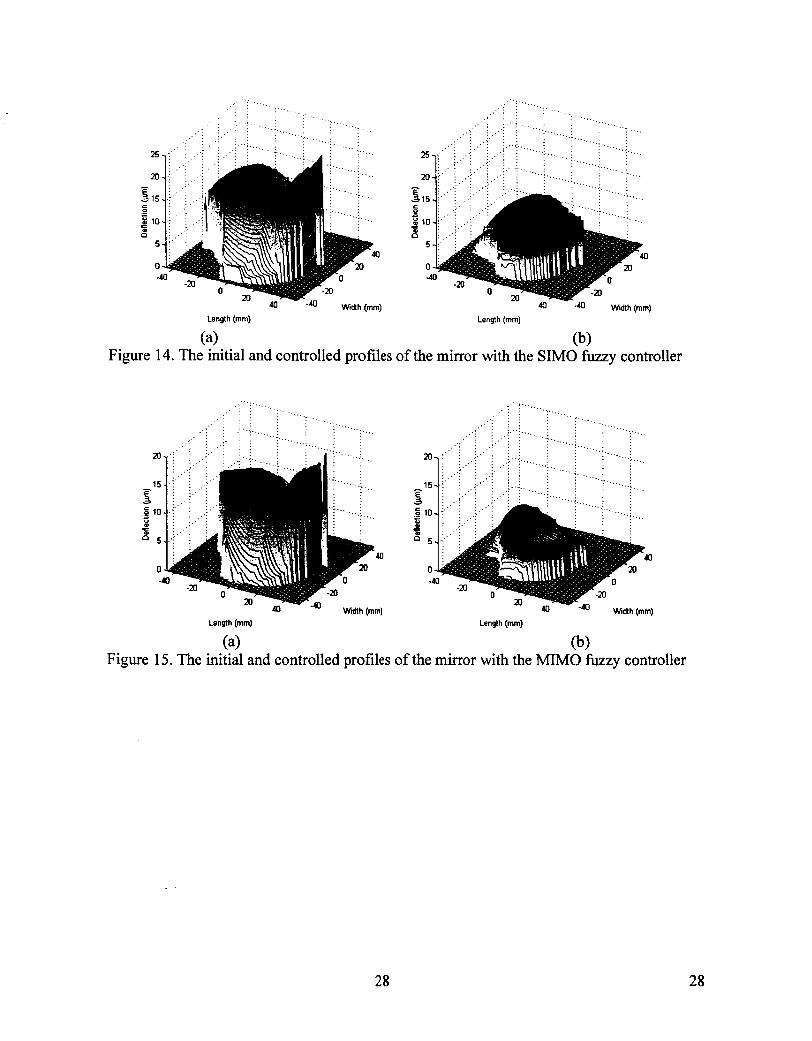
Figures 14a and 14b show the initial and controlled profiles of the bimorph mirror
with the SlMO fuzzy controller while figures 15a and 15b show the initial and controlled
profiles of the mirror with MlMO fuzzy controller, respectively. The experimental results
illustrate that the fuzzy control methods are more effective for shape control, but these
control methods cannot produce a desired shape of the mirror since the collision
mechanism of electrons on a PZT-5H sheet is complex. Actually, the shape of the mirror
is adjusted by controlling the electric field across its thickness. The net electric field is
the result of the potential on the PZT-SH wafer and the potential of the mirror/electrode
controlled by a power amplifier. The accumulation amount and distribution position of
electrons on the PZT-5H wafer are important factors for inducing deformation on the
mirror. They are not only determined by control voltages ( V,,V, ), but also by
accumulated electrons on the back of the mirror. Future work includes the development
of a more robust intelligent control method that is able to correct the bimorph mirror into
any desired shape. _ .
16 16
5. Conclusions
The purpose of this research is to form and develop a simple closed-loop control
system with fuzzy logic for non-contact electron gun control of a bimorph mirror. A SlMO
and a MlMO fuzzy inference mechanism based on previous experimental results was
derived to construct two fuzzy logic controllers for non-contact shape control of the
mirror. A wavefront sensor was used as the feedback device. Both the SlMO and MlMO
models demonstrated the ability to correct the mirror deformation. Due to the complexity
of the excitation process, the closed loop control between the measured shape and
corrective electron gun actuation with fuzzy logic is still not a perfect solution, but
experimental results show that the fuzzy logic control methods are effective in correcting
the shape of the mirror to a desired shape, though not with total accuracy. Further work
is necessary to develop an adaptive intelligent control method so that the control model
can be trained in the control process.
References
I. Feinleib, J. Lipson, G. and Cone P. F. "Monolithic piezoelectric mirror for wavefront correction", Applied Physics Letters 1974 Vo1.25, No.5 pp311-313
2. Steinhaus, E, Lipson, S.G, "Bimorph piezoelectric flexible mirror" Journal of the Optical Society of America, 1979, Vo1.69 pp. 478-481
3. Forbes, F., Roddier, F., Poczulp, G., Pinches, C., Sweeny, G. and Dueck, R., "Segmented bimorph deformable mirror", Journal of Physics E: Scientific Instruments, 1989, V01.22 pp402-405
17 17
4. Susini, J., D. Labergerie and L. Zhang. “Compact active/adaptive X-ray mirror:bimorph piezoelectric flexible mirror.” Review of Scientific lnstruments (1995), V01.66 ~~2229-2231.
5. Kuo, CP, Wada BK. Composite deformable mirror. Active Telescope Systems 1989;Vol. 1 1 14, pp 495-505
6. Paradies, R., Hertwig, M. “Shape control of adaptive composite reflectors”, Composites: Part 6. 1999, Vo1.30 pp65-78
7. Song, H and Main, J. A, “Non-contact closed loop control system of optic deformable mirrors” in preparation.
8. Hubbard, J. “Active mirror assembly” United States Patent, #5,159,498 October, 1992
9. Main, J.A, Nelson, G.C, “Smart material control system and related method”, United States Patent#6,188,160 February, 2001.
I O . Nelson, G.C., Main, J.A., “Non-contact Electron Gun Strain Control of Piezoceramics” A I M Journal, 2001 , Vol. 39, No. 9, pp. 1808-1 81 3.
11. Martin, J., Main, J. A, and Nelson, G. C, “Shape Control of Deployable Membrane Mirrors,” Proceedings of the ASME International Mechanical Engineering Congress and Exposition, Adaptive Structures and Material Systems, Anaheim California, November 15-20, 1998, AD-Vol. 57, pp. 217-223.
12. Ganachaud, J.P, Mokrani, A. “Theoretical Study of the Secondary Electron Emission of Insulating Target” Surface Science 1995, Vol. 334, No. 1-3, pp329- 341.
13. Nguyen, H.T. and Sugeno, M. “Fuzzy Systems Modeling and Control”, Kluwer Academic Publishers, 1998
14. Neal, D.R. Armstrong, D.J. and Turner, W.T. “Wavefront sensors for control and process monitoring in optics manufacture” SPlE 2993(29) 1997
18 18

Table 1 . Material Properties of PZT-SH
Properties Unit Value c,. 1 Oi0Nrn-' Cll= C22=12.72, C12=8.O2,
Ci3= C23=8.47, &=11.74, c44= c55=2.30
~ ~~
v b
DS
D, DM
DL
Table 2. Rule bases of MIMO fuzzy model
W C
NL NS Z PS PL
PLL PM Z NM NLL
PLS PSL Z NSL NLS
PM PSS Z NSS NM
V C
DS
Dc DM
DL
W,
NL NS Z PS PL
SS SM SS LM LL
SMS SML SS LMS LML
SM SL SS LS LM
DS LL LM
D,
SS SM SL DS
I I I I
SL SML SS LML LL
19 19
Wavefront SensorWS) r -T- I Laser
1
Vacuum Chamber /
Bimotph Mirror
Screen Collector
/
Analysis Computer
jeBeam j I 1
Backpressure Voltage r- Amplifier
! I i Electron j Gun j
! j
Collector Voltage Amplifier
4 +, Converter Counter
Converter r------ Electron
Gun Power Digital I/O
supply
I I I I
t Digital I10 0 Converter 3
I Controller dSPACE I Profile of mirror ?
Figure 1. The experimental setup
20 20
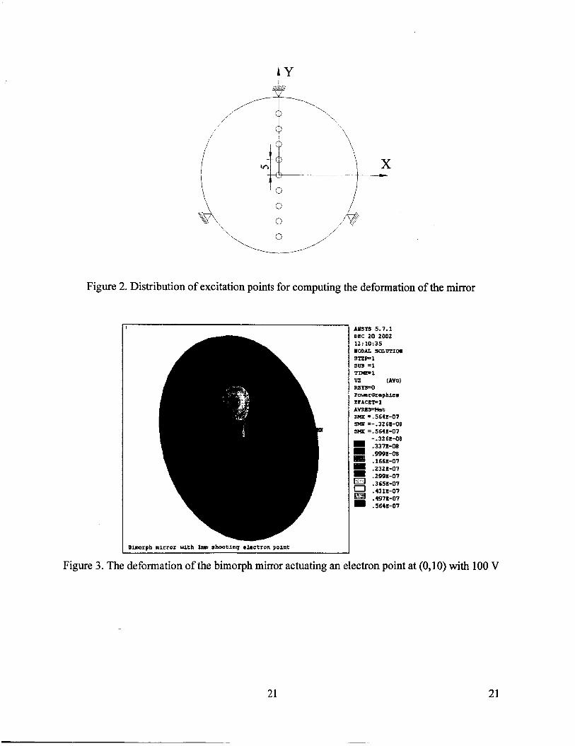
Figure 2. Distribution of excitation points for computing the deformation of the mirror
DEC 20 2002 12 : 10 : 35 PODU S-WTIOI STEP1 s w =1 T-1 uz I A W R S Y S O PouccGcaphic8 EIACKFl AVRCIFMat DHX =. 5643-017 ?MI =-.3261-08 SHX =.564K-07
- .3261-08 .33?1-08
.1663-07
.23211-07
.2991-07
- .999E-08 u .4311-07
.4971-07
.5641-07
Bimrph mirror with lnol shooting electron point I Figure 3. The deformation of the bimorph mirror actuating an electron point at (0,lO) with 100 V
21 21
n 7
0.65
0.6 E E 0.55
0.5
0.45
E 0.4
0.35
0.3
0.25
2 0 .- - c a -0
.- z E
-
-
-
-
-
-
-
-
-
1
-2( 0.2
-I( -1: -5 15 Position of actuating point on Y(mm)
Figure 4. Maximum deflections on the mirror actuated at different positions with the same voltage
Shape error W(k+l) b
w(k) Controller w(k) Controller Analysis
X2o.Y2(kr- TmimR- W k ) T Figure 5. Block diagram of the feedback control system
- Wl(k) -
EG W(k+l) Localizing WFS - Shape error
Adysls w c ) Controller xzO.y2(kr.-
b
Figure 6. Block diagram of the fizzy control system
22 22

wc (w) Figure 7. Membership function representation of deflection input
0 0.5 1 1.5 2 2.5 3 3.5 4 Te(Sl
Figure 8. Membership function representation of output variables
23 23
Dc (mm)
Figure 9. Membership function representations of input variables
1
0.8
0.6
0 A
0.2
0 ~ ' V V " ' " -600 -400 -200 0 200 400 600 800 1000
Vb (voits)
1
0.8
0.6
0.4
0.2
SS SMS SM SML SL LS LMS LM LML LL
Figure 10. Membership hction representations of Vb and Vc
24 24
1 SS SMS SM SML SL LS LMS LM LML LL
0.8
0.6
0.4
0.2
n 300 300 400 500 600 700 800
Ve (volts)
SS SMS SML SL LS LMS LML LL
"0 0.5 1 1.5 2 2.5 3 3.5 4 4.5 Te (seconds)
Figure 1 1. Membership function representations of Ve and Te
I. .
25 25
Closed-loop steps
(a)
Closed-loop steps
Figure 12. The deflection response using the SIMO fuzzy controller (a) Absolute maximum deflection (b) Madmin deflection
26 26
"0 1 2 3 4 5 6 7 E 9 10 Closed-loop steps
(a)
I Closed-loop steps
Figure 13. The deflection response using the MIMO fuzzy controller 0.9
(a) Absolute maximum deflection (b) Madmin deflection
27 27
. . . . . . . . . . . . . . . . . . . . . . . . . . . . . . . . . . . . . . . . . . . . . . . . . . . . . . . . . . .
x..:,' : ,:: : :: . . . . . . 4 .
Length (mm) Length (mm)
(a) (b) Figure 14. The initial and controlled profiles of the mirror with the SIMO fuzzy controller
.... . . _ . . . . . . . . . . . . . . . . . . . . . . . . . . . . . . I . . . . . . . . ' ..... : . . . . . . :. . ....
. . . . . . . .
Length (mm) Lenglh (mm)
(a) (b) Figure 15. The initial and controlled profiles of the mirror with the MIMO fuzzy controller
28 28