Embed Size (px)
Citation preview
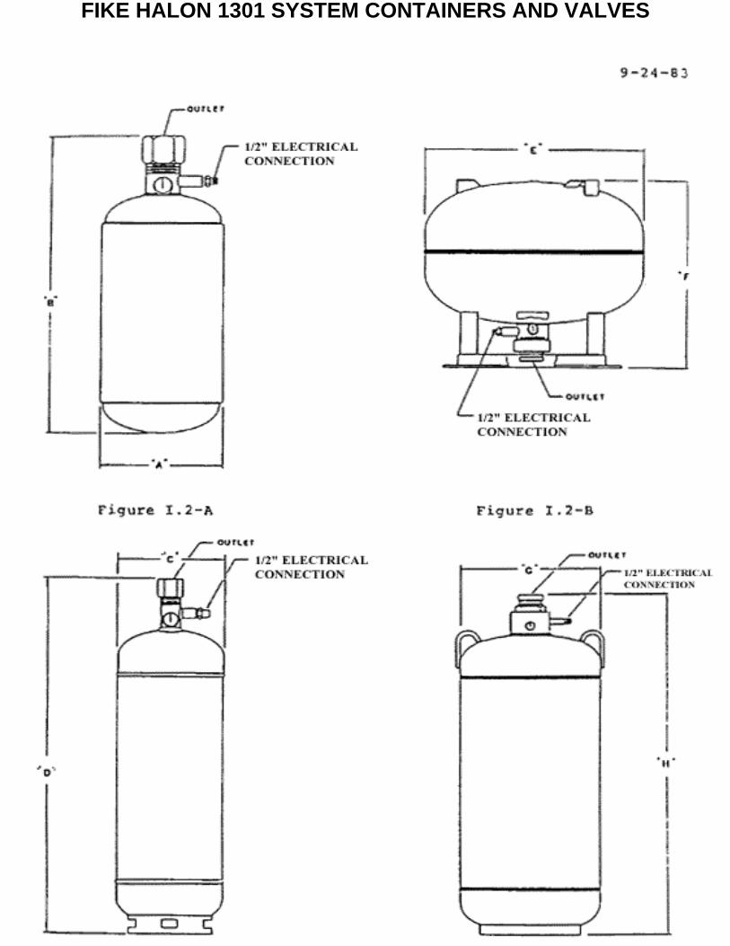
FIKE HALON 1301 SYSTEM CONTAINERS AND VALVES
U.L. EX28287/10/88
III.6 CONTAINER ELECTRICAL CONNECTIONS
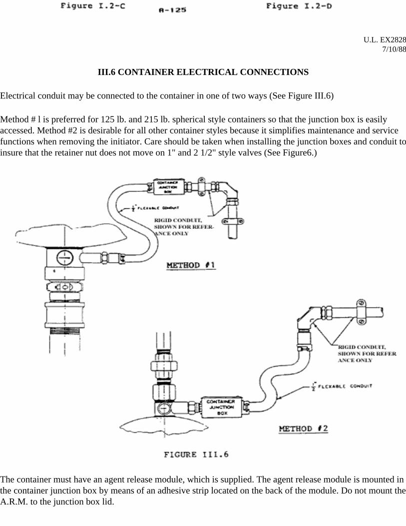
Electrical conduit may be connected to the container in one of two ways (See Figure III.6)
Method # l is preferred for 125 lb. and 215 lb. spherical style containers so that the junction box is easily accessed. Method #2 is desirable for all other container styles because it simplifies maintenance and service functions when removing the initiator. Care should be taken when installing the junction boxes and conduit to insure that the retainer nut does not move on 1" and 2 1/2" style valves (See Figure6.)
The container must have an agent release module, which is supplied. The agent release module is mounted in the container junction box by means of an adhesive strip located on the back of the module. Do not mount the A.R.M. to the junction box lid.
System wiring will vary from system to system and depending on the type of control system used. Consult system plans and the appropriate control manuals for specific system wiring information.
III.6.1 INITIATOR INSTALLATION
Read and understand this section before attempting to install initiators.
All system components must be installed, and the electrical and control systems thoroughly checked out by a factory trained technician as outlined in Section IV before proceeding with the initiator installation.
WARNING:
Initiators are small pyrotechnic devices that can cause bodily injury and equipment damage if improperly handled. Read and understand this entire section before installing initiators. Accidental activation will not occur when the procedures in this section are followed.
Initiators employed in the Fike System are widely used in industrial applications and must be respected for their extremely fast response and the possibility of accidental detonation. When initiators are handled properly, accidental detonation will not occur.
Safety procedures which should be observed when handling initiators are as follows:
A. Control panel must be disabled prior to servicing.B. Initiators must remain shunted at all times until installed into a thoroughly checked-out Fike System.C. When handling or installing initiators, approved eye protection must be worn.D. Never handle, or have in your possession, more than one initiator at any given time.E. Do not handle these devices when wearing static producing clothes or shoes.F. Do not expose initiators to high heat sources as this may greatly affect the service life.G. Do not check initiator continuity with any type of ohm meter or other device.H. If an initiator is suspected of being defective, return it to the factory or Fike distributor for proper
disposal.I. Two types of initiator assemblies are used. One type is used for 1" and 2 1/2" discharge valves. The
other type is used in 3" discharge valves. Each type has it's own thread size and should only be used for the valve size intended.
J. Do not install initiators if ground faults are present in the system.K. Do not install initiators if voltage is present on conduit or equipment.L. Do not install initiator if radio transmitters are being used in nearby areas.
M. Connect initiator leads only after the assembly has been installed in the container discharge valve.
After the electrical and control systems have been checked out, proceed with the initiator installation step by step as follows:
Step 1: Move the "armed/disabled" switch on the control panel to the "disabled" position.
Step 2: Wait a minimum of 10 minutes to allow capacitors in initiator modules to dissipate their electrical charge.
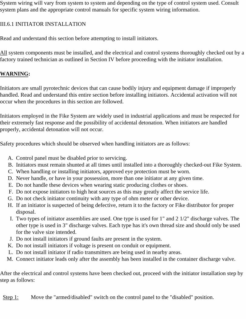
Step 3: Unwrap initiator leads and screw the threaded portion of the assembly into the retainer nut (or initiator boss on 3" valves) and tighten to approximately 40 inch pounds (See Figure III.6.1).
Step 4: Pass leads through hole in electrical box or conduit if they were removed and reinstall.
Step 5: With shunt intact, strip about 1/2" of insulation on each lead about 2 inches back from the shunt.
Step 6: Insert stripped sections of initiator leads under center screw terminals (no polarity requirement) located on the agent release module and tighten screw terminals (See Figure III.1.10-B for pictorial clarification).
Step 7: Repeat steps 3 thru 6 for all containers in the system.
Step 8: Clip shunts off of all initiator leads and close all electrical boxes.
Step 9: Check control panel for any trouble indication other than the one caused by the "armed/disabled" switch being in the "disable" condition.
Step 10: If no other trouble conditions exist, move the "armed/disabled" switch to the "armed" position and reset the control panel.
The Containers Are Now Armed!
WARNING:
Do not "ARM" the system if a ground fault indication is present.
Every three months:
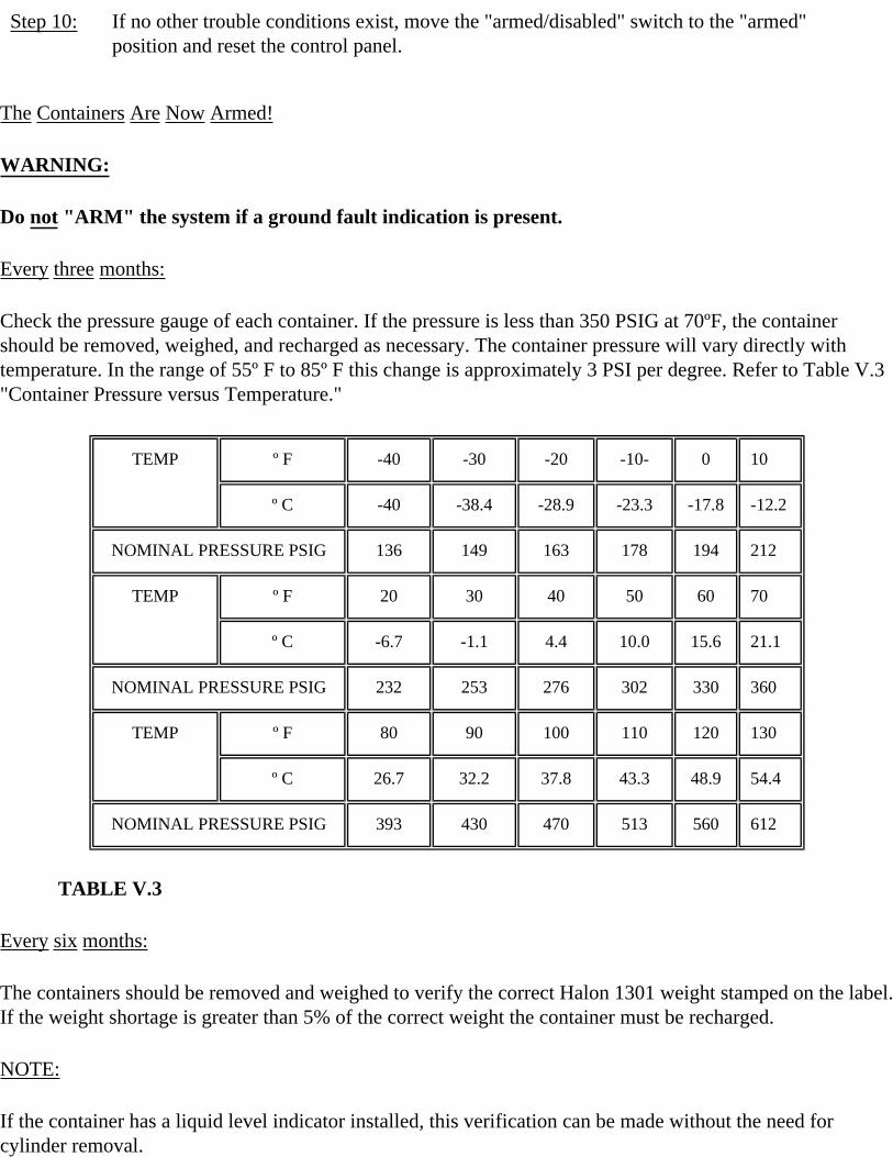
Check the pressure gauge of each container. If the pressure is less than 350 PSIG at 70ºF, the container should be removed, weighed, and recharged as necessary. The container pressure will vary directly with temperature. In the range of 55º F to 85º F this change is approximately 3 PSI per degree. Refer to Table V.3 "Container Pressure versus Temperature."
TEMP º F -40 -30 -20 -10- 0 10
º C -40 -38.4 -28.9 -23.3 -17.8 -12.2
NOMINAL PRESSURE PSIG 136 149 163 178 194 212
TEMP º F 20 30 40 50 60 70
º C -6.7 -1.1 4.4 10.0 15.6 21.1
NOMINAL PRESSURE PSIG 232 253 276 302 330 360
TEMP º F 80 90 100 110 120 130
º C 26.7 32.2 37.8 43.3 48.9 54.4
NOMINAL PRESSURE PSIG 393 430 470 513 560 612
TABLE V.3
Every six months:
The containers should be removed and weighed to verify the correct Halon 1301 weight stamped on the label. If the weight shortage is greater than 5% of the correct weight the container must be recharged.
NOTE:
If the container has a liquid level indicator installed, this verification can be made without the need for cylinder removal.
When removing the container for weighing, the control system must be in the "disabled" position and the initiators shunted and removed.
Reinstall the containers and initiators according to the Procedures in the system installation section of this manual.
V.3.1. VALVE RECONDITIONING
After the container has been discharged, the valve will need to be reconditioned using the appropriate reload kit.
If the container was not discharged, and a leaky valve needs to be reconditioned, the contents of the container should be emptied or transferred to another container before reconditioning the valve.
WARNING:
Container contents are under high pressure, therefore, never attempt to rebuild the valve until the contents are emptied and the pressure gauge reads 0 PSIG.
Care should be taken when handling valve components to avoid damage of any kind. Be careful not to bend, poke, or otherwise distort the valve rupture discs as their service may adversely be affected.
V.3.1.1 1" IN VALVE (5 lb., 10 lb., 20 lb., 35 lb., 60 lb., and 100 lb. containers)
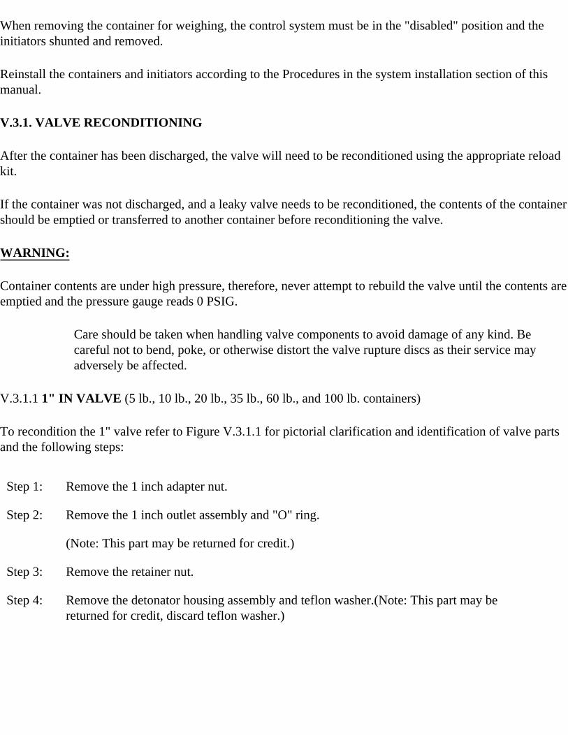
To recondition the 1" valve refer to Figure V.3.1.1 for pictorial clarification and identification of valve parts and the following steps:
Step 1: Remove the 1 inch adapter nut.
Step 2: Remove the 1 inch outlet assembly and "O" ring.
(Note: This part may be returned for credit.)
Step 3: Remove the retainer nut.
Step 4: Remove the detonator housing assembly and teflon washer.(Note: This part may be returned for credit, discard teflon washer.)
ITEM NO
DESCRIPTION REPLACEMENT PART
1 BAFFLE PLUG
2 ADAPTER NUT
3 OUTLET ASSEMBLY X
4 "O" RING X
5 TEFLON WASHER X
6 DETONATOR HOUSING ASSEMBLY X
7 RETAINER NUT
8 INITIATOR ASSEMBLY (70-1058) X
Step 5: Clean all debris from teflon washer and "O" ring seating surfaces with fine emery cloth. Surfaces must be dirt and rust free. Clean all threads and blow out all valve areas with an air gun.
Step 6: Place new teflon washer on new detonator housing assembly and reinstall in valve initiator boss.
Step 7: Reinstall retainer nut and torque to 90-150 inch pounds. Do Not Over tighten!
Step 8: Apply a light film of Dow Corning silicone sealer (or equal) to "O" - ring seating surface.
Step 9: Install new "O"-ring on outlet assembly. Install outlet assembly and tighten until assembly bottoms out.
Step 10: Remove and replace valve core in the brass fill valve located on the side of the discharge valve.
Step 11: Reinstall the adapter nut and baffle plug.
The container is now ready for recharging.
V.3.2.2 2 1/2" VALVE (70-041, 125 lb., and 70-077, 215 lb. containers)
To recondition the 2 1/2" valve, refer to Figure V.3.1.2 for pictorial clarification and identification of valve parts and the following steps:
Step 1: Remove grooved coupling and baffle plate from valve outlet.
Step 2: Remove holddown nut using left-hand spanner wrench (available from Fike).
Step 3: Remove holddown ring, "O"-ring, and rupture disc. Discard rupture disc and "O"-ring.
Step 4: Remove detonator housing and teflon washer. Discard washer. (Note: Detonator housing may be returned for credit).
Step 5: Clean all debris from teflon washer and "O"-ring seating surfaces with fine emery cloth. Surfaces must be dirt and rust free. Clean all threads and blow out all valve areas with an air gun.
Step 6: Place new teflon washer on new detonator housing assembly and reinstall in valve initiator boss.
ITEM NO
DESCRIPTION REPLACEMENT PART
1 BAFFLE PLATE
2 VICTAULIC COUPLING
3 HOLDDOWN NUT
4 HOLDDOWN RING
5 RUPTURE DISC X
6 "O" RING X
7 TEFLON WASHER X
8 DETONATOR HOUSING ASSEMBLY X
9 RETAINER NUT
10 INITIATOR ASSEMBLY (70-1058) X
Step 7: Reinstall retainer nut and torque to 90 - 150 inch pounds. Do not over tighten!
Step 8: Apply a thin film of Dow Corning silicone vacuum grease (or equal) to "O"-ring groove and place new "O"-ring into groove.
Step 9: Install new rupture disc, convex side up, and place holddown ring centered over rupture disc.
Step 10: Reinstall holddown nut and torque to 60 foot pounds or use the following method: Spin holddown nut on by hand and tighten hand tight. Further tighten with right hand spanner wrench 1/3 turn minimum. (Wrench available through Fike).
Step 11: Remove and replace valve core in the brass fill valve located on the side of the discharge valve.
Step 12: Reinstall the grooved coupling and baffle plate.
The container is now ready for recharging.
V.3.1.3 3" VALVE (70-087, 215 lb., 375 lb., 650 lb., and 1000lb. Containers)
To recondition the 3" valve, refer to Figure V.3.1.3 for pictorial clarification and identification of valve parts and the following steps:
Step 1: Remove grooved coupling and baffle plate.
Step 2: Remove holddown nut using a left or right handed spanner wrench (available through Fike).
Step 3: Remove the valve assembly containing the two rupture discs.
Step 4: Remove siphon tube assembly and "O"-rings.
Step 5: Clean all debris from "O"-ring grooves and flat seating surface in bottom of valve body using fine emery cloth. Surface must be dirt and rust free. Clean all threads and blow out all valve areas with an air gun.
Step 6: Apply a thin coating of Dow Corning silicone vacuum grease (or equal) to "O"-ring grooves and flat seating surface in valve body.
Step 7: Place new "O"-rings in grooves and reinstall siphon tube assembly making sure it rests squarely on the flat seating surface.
ITEM NO
DESCRIPTION REPLACEMENT PART
1 BAFFLE PLATE
2 VICTAULIC COUPLING
3 HOLDDOWN NUT
4 HOLDDOWN RING
5 VALVE ASSEMBLY X
6 "O" RING X
7 SIPHON TUE ASSEMBLY
8 INITIATOR ASSEMBLY (70-1336) X
Step 8: Apply a thin coating of Dow Corning Silicone Vacuum grease (or equal) to top "O"-ring and siphon tube assembly.
Step 9: Install new valve assembly with bulged rupture disc pointing up. Initiator boss on valve assembly must point through slot on valve body.
Step 10: Center holddown ring on top of the rupture disc on valve assembly. Spin holddown nut on until hand tight. Tighten nut with left or right hand spanner wrench until nut no longer turns.
Step 11: Remove and replace valve core in brass fill valve located on the side of the discharge valve.
Step 12: Reinstall the grooved coupling and baffle plate
The container is now ready for recharge.
V. 4 INITIATORSWARNING:
Initiators are small pyrotechnic devices that can cause bodily injury and equipment damage if improperly handled. Refer to Section III.6.1 for proper handling of initiators.
Before checking or servicing initiators, move the "armed/disabled" switch on the system control panel to the "disabled" position. Allow ten minutes for the capacitors the initiator modules to dissipate their charge.
Every six months:
Check initiator leads and wiring to initiator modules for corrosion. Also, check for loose or broken wires.
Every Five Years:
Replace initiators. Refer to Section III.6.1 for initiator installation.
V.5 CONTAINER TEST AND INSPECTION
Halon 1301 containers shall not be recharged without a retest if more than five years have elapsed since the last test. The retest consists of a complete external and internal visual inspection in accordance with the Code of Federal Regulations, Title 49, Section 173.34(e)(10). The C.F.R. requirements also refer you to the Compressed Gas Association Pamphlet C-6, Section 3.
Cylinders continuously in service without discharging shall be given a complete external visual inspection every five years. The cylinder does not need to be emptied for this inspection.
All visual inspections must be performed according to the regulations of C.F.R. Title 49, and C.G.A.

Pamphlet C-6, Section 3. All inspections are to be done by C.G.A./D.O.T. approved inspectors only.
Return to Table of Contents
GINGE KERR HALON 1301SYSTEM VALVES
Release panel 5444 P32
GINGE MALSKITSEHALON 1301 Ventil 1 ¼ "
Type 06-6441-00UDGAVE M-01
1. Bursting Disc: 190 bar2. Leek valve w/indicator for pressure operated release3. Fitting for actuators4. Fitting for pressure gauge or switch5. Discharge outlet6. O-ring
Working pressure: 100 barpressure: 150 barWeight: 3.7 kgMaterial: Brass