Embed Size (px)
Citation preview
Quick reference
R410A
FILE NO. :A11-005
Refrigerant Piping
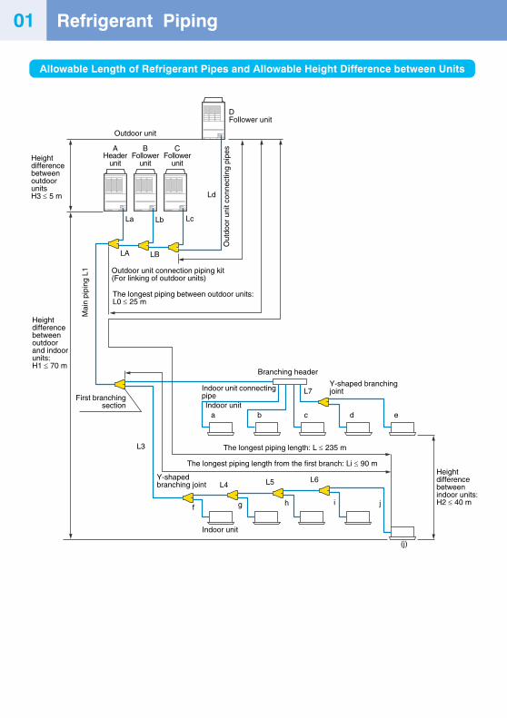
Allowable Length of Refrigerant Pipes and Allowable Height Difference between Units
DFollower unit
HeightdifferencebetweenoutdoorunitsH3 ≤ 5 m
Heightdifferencebetweenindoor units:H2 ≤ 40 m
Outdoor unit
Ld
LcLbLa
LBLA
Outdoor unit connection piping kit(For linking of outdoor units)
Out
door
uni
t con
nect
ing
pipe
s
The longest piping between outdoor units:L0 ≤ 25 m
Mai
n pi
ping
L1
Heightdifferencebetweenoutdoorand indoorunits:H1 ≤ 70 m
First branchingsection
L3
Y-shapedbranching joint L4 L5 L6
Indoor unit
f g h i j
The longest piping length from the first branch: Li ≤ 90 m
The longest piping length: L ≤ 235 m
Indoor unita b c d e
(j)
Indoor unit connectingpipe
Branching header
Y-shaped branchingjointL7
AHeader
unit
BFollower
unit
CFollower
unit
01
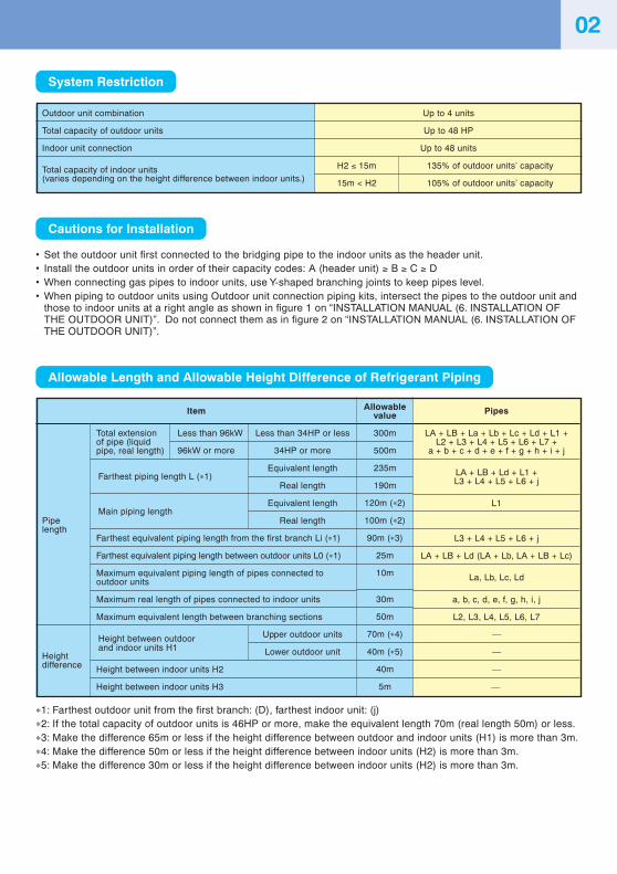
System Restriction
Cautions for Installation
• Set the outdoor unit first connected to the bridging pipe to the indoor units as the header unit.• Install the outdoor units in order of their capacity codes: A (header unit) ≥ B ≥ C ≥ D• When connecting gas pipes to indoor units, use Y-shaped branching joints to keep pipes level.• When piping to outdoor units using Outdoor unit connection piping kits, intersect the pipes to the outdoor unit and
those to indoor units at a right angle as shown in figure 1 on “INSTALLATION MANUAL (6. INSTALLATION OFTHE OUTDOOR UNIT)”. Do not connect them as in figure 2 on “INSTALLATION MANUAL (6. INSTALLATION OFTHE OUTDOOR UNIT)”.
Allowable Length and Allowable Height Difference of Refrigerant Piping
∗1: Farthest outdoor unit from the first branch: (D), farthest indoor unit: (j)∗2: If the total capacity of outdoor units is 46HP or more, make the equivalent length 70m (real length 50m) or less.∗3: Make the difference 65m or less if the height difference between outdoor and indoor units (H1) is more than 3m.∗4: Make the difference 50m or less if the height difference between indoor units (H2) is more than 3m.∗5: Make the difference 30m or less if the height difference between indoor units (H2) is more than 3m.
Outdoor unit combination
Total capacity of outdoor units
Indoor unit connection
Total capacity of indoor units(varies depending on the height difference between indoor units.)
Up to 4 units
Up to 48 HP
Up to 48 units
H2 ≤ 15m 135% of outdoor units’ capacity
15m < H2 105% of outdoor units’ capacity
02
Total extensionof pipe (liquidpipe, real length)
Farthest piping length L (∗1)Equivalent length
Real length
Main piping lengthEquivalent length
Real length
Farthest equivalent piping length from the first branch Li (∗1)
Farthest equivalent piping length between outdoor units L0 (∗1)
Maximum equivalent piping length of pipes connected tooutdoor units
Maximum real length of pipes connected to indoor units
Maximum equivalent length between branching sections
Height between outdoor Upper outdoor units
and indoor units H1 Lower outdoor unit
Height between indoor units H2
Height between indoor units H3
Pipelength
Heightdifference
Item
Less than 96kW Less than 34HP or less
96kW or more 34HP or more
Allowablevalue
300m
500m
235m
190m
120m (∗2)
100m (∗2)
90m (∗3)
25m
10m
30m
50m
70m (∗4)
40m (∗5)
40m
5m
Pipes
LA + LB + La + Lb + Lc + Ld + L1 +L2 + L3 + L4 + L5 + L6 + L7 +
a + b + c + d + e + f + g + h + i + j
LA + LB + Ld + L1 +L3 + L4 + L5 + L6 + j
L1
L3 + L4 + L5 + L6 + j
LA + LB + Ld (LA + Lb, LA + LB + Lc)
La, Lb, Lc, Ld
a, b, c, d, e, f, g, h, i, j
L2, L3, L4, L5, L6, L7
—
—
—
—
Adding Refrigerant03
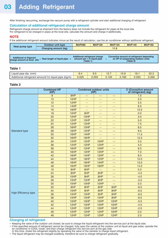
After finishing vacuuming, exchange the vacuum pump with a refrigerant cylinder and start additional charging of refrigerant.
Calculation of additional refrigerant charge amountRefrigerant charge amount at shipment from the factory does not include the refrigerant for pipes at the local site.For refrigerant to be charged in pipes at the local site, calculate the amount and charge it additionally.
NOTEIf the additional refrigerant amount indicates minus as the result of calculation, use the air conditioner without additional refrigerant.
Heat pump typeOutdoor unit type MAP080 MAP100 MAP120 MAP140 MAP160
Charging amount (kg) 11.5
Table 1
Liquid pipe dia. (mm)Additional refrigerant amount/1m liquid pipe (kg/m)
6.40.025
9.50.055
12.70.105
15.90.160
19.10.250
22.20.350
Table 2
Standard type
High Efficiency type
Combined HP(HP)
810121416182022242628303234363840424446481624262830323436384042444648
Combined outdoor units(HP)
8HP — — —10HP — — —12HP — — —14HP — — —16HP — — —10HP 8HP — —10HP 10HP — —12HP 10HP — —12HP 12HP — —16HP 10HP — —16HP 12HP — —16HP 14HP — —16HP 16HP — —12HP 12HP 10HP —12HP 12HP 12HP —16HP 12HP 10HP —16HP 12HP 12HP —16HP 14HP 12HP —16HP 16HP 12HP —16HP 16HP 14HP —16HP 16HP 16HP —8HP 8HP — —8HP 8HP 8HP —
10HP 8HP 8HP —10HP 10HP 8HP —10HP 10HP 10HP —8HP 8HP 8HP 8HP
10HP 8HP 8HP 8HP10HP 10HP 8HP 8HP10HP 10HP 10HP 8HP10HP 10HP 10HP 10HP12HP 10HP 10HP 10HP12HP 12HP 10HP 10HP12HP 12HP 12HP 10HP12HP 12HP 12HP 12HP
C (Corrective amountof refrigerant) (kg)
1.52.53.58.5
10.50.03.05.07.58.59.5
11.512.53.04.06.07.08.0
10.012.014.00.0-4.0-4.0-2.00.0-6.0-6.0-6.0-6.0-5.0-4.0-2.00.02.0
Additional re frigerant Additional refrigerant charge Corrective amount of refrigerant depending
charge amount at local site = Real length of liquid pipe × amount per 1 m liquid pipe + on HP of cooperating outdoor units(Table 1) (Table 2)
Charging of refrigerant• Keeping the valve of the outdoor unit closed, be sure to charge the liquid refrigerant into the service port at the liquid side.• If the specified amount of refrigerant cannot be charged, fully open the valves of the outdoor unit at liquid and gas sides, operate the
air conditioner in COOL mode, and then charge refrigerant into service port at the gas side.In this time, choke the refrigerant slightly by operating the valve of the canister to charge liquid refrigerant.
• The liquid refrigerant may be charged suddenly, therefore be sure to charge refrigerant gradually.
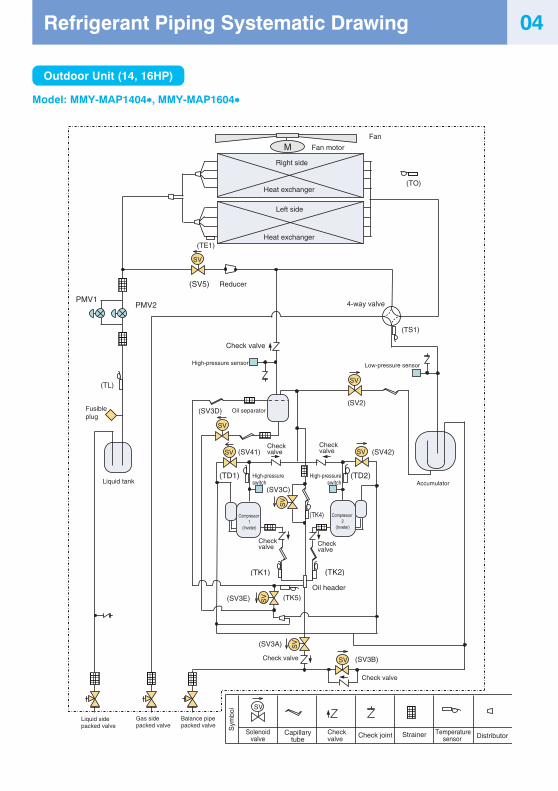
Liquid tank
(TL)
PMV14-way valve
Check valve
High-pressure sensor
(TD2)Accumulator
(TS1)
(SV2)
Low-pressure sensor
(SV5)
(TE1)
M
(SV3D)
PMV2
(TK2)
Right side
(SV3B)
(TK1)
(SV3A)
(TD1)
(TK4)
(SV3E) (TK5)
A3
Oil header
Oil separator
Fan
(SV3C)
Reducer
(TO)
SV
SV
SV
SV
SV
SV
SV
SV
SV
SV
Heat exchanger
Left side
Fan motor
FP
Heat exchanger
Fusible plug
Check valve
Check valve
Check valve
Check valve
Check valve
Check valve
Check valve
(SV41) (SV42)
High-pressureswitch
High-pressureswitch
Compressor 2
(Inveter)
Compressor 1
(Inveter)
Liquid sidepacked valve
Gas sidepacked valve
Balance pipepacked valve S
ymbo
l
Solenoidvalve
Capillarytube
Check joint Strainer Temperaturesensor Distributor
Outdoor Unit (14, 16HP)
Model: MMY-MAP1404∗∗∗∗∗, MMY-MAP1604∗∗∗∗∗
04Refrigerant Piping Systematic Drawing
05
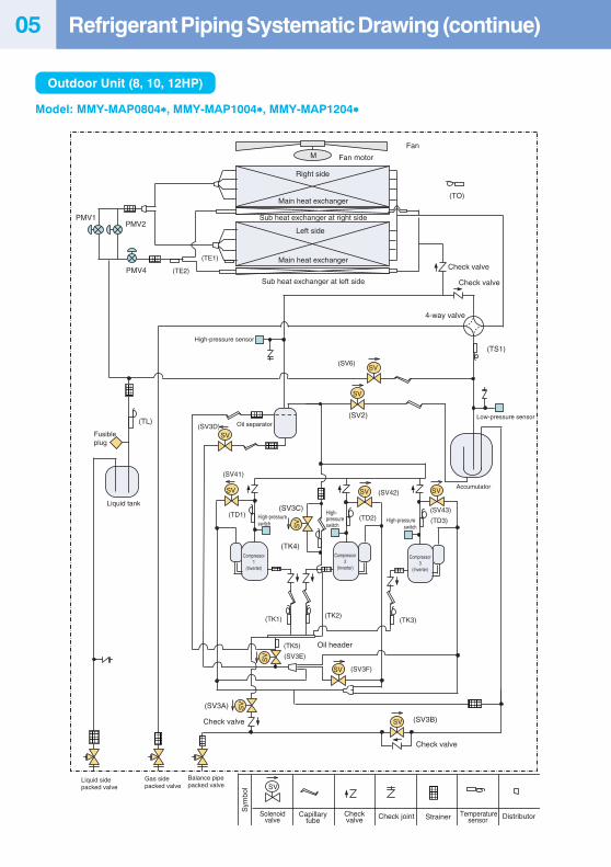
(TL)
PMV1
(TD2)
(TS1)
(SV2) Low-pressure sensor
(TE1)
M
(SV3D)
PMV2
(TK2)
(SV3B)
(TK1)
(SV3A)
(TD1)
(TK4)
(SV3E)
(TK5)
(SV41)
(SV42)
PMV4
Fan
(TE2)
Sub heat exchanger at left side
(TD3)
(SV43)
(TK3)
(SV6)
(TO)
(SV3F)
(SV3C)
SV
SV
SV
SV SVSV
SV
SV
SV
SV
SV
Main heat exchanger
Main heat exchanger
Sub heat exchanger at right side
Fan motor
FP
SV
Sym
bol
Solenoidvalve
Capillarytube
Checkvalve Check joint Strainer Temperature
sensor Distributor
Right side
Left side
Check valve
Check valve
4-way valve
High-pressure sensor
Fusible plug
Liquid tank
Oil separator
High-pressure switch
High-pressure switch
High-pressure switch
Accumulator
Oil header
Compressor1
(Inverter)
Compressor2
(Inverter)
Compressor3
(Inverter)
Check valve
Check valve
Liquid sidepacked valve
Gas sidepacked valve
Balance pipepacked valve
Outdoor Unit (8, 10, 12HP)
Model: MMY-MAP0804∗∗∗∗∗, MMY-MAP1004∗∗∗∗∗, MMY-MAP1204∗∗∗∗∗
Refrigerant Piping Systematic Drawing (continue)
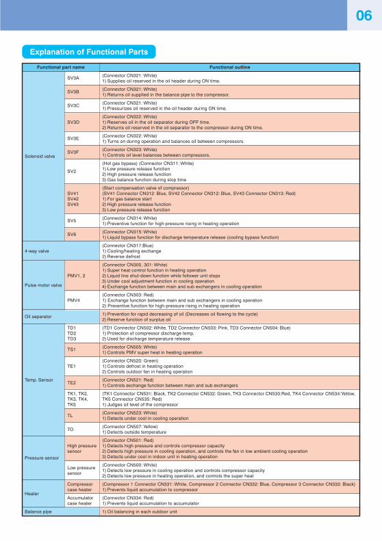
Functional outline
(Connector CN321: White)1) Supplies oil reserved in the oil header during ON time.
(Connector CN321: White)1) Returns oil supplied in the balance pipe to the compressor.
(Connector CN321: White)1) Pressurizes oil reserved in the oil header during ON time.
(Connector CN322: White)1) Reserves oil in the oil separator during OFF time.2) Returns oil reserved in the oil separator to the compressor during ON time.
(Connector CN322: White)1) Turns on during operation and balances oil between compressors.
(Connector CN323: White)1) Controls oil level balances between compressors.
(Hot gas bypass) (Connector CN311: White)1) Low pressure release function2) High pressure release function3) Gas balance function during stop time
(Start compensation valve of compressor)(SV41 Connector CN312: Blue, SV42 Connector CN312: Blue, SV43 Connector CN313: Red)1) For gas balance start2) High pressure release function3) Low pressure release function
(Connector CN314: White)1) Preventive function for high-pressure rising in heating operation
(Connector CN315: White)1) Liquid bypass function for discharge temperature release (cooling bypass function)
(Connector CN317:Blue)1) Cooling/heating exchange2) Reverse defrost
(Connector CN300, 301: White)1) Super heat control function in heating operation2) Liquid line shut-down function while follower unit stops3) Under cool adjustment function in cooling operation4) Exchange function between main and sub exchangers in cooling operation
(Connector CN303: Red)1) Exchange function between main and sub exchangers in cooling operation2) Preventive function for high-pressure rising in heating operation
1) Prevention for rapid decreasing of oil (Decreases oil flowing to the cycle)2) Reserve function of surplus oil
(TD1 Connector CN502: White, TD2 Connector CN503: Pink, TD3 Connector CN504: Blue)1) Protection of compressor discharge temp.2) Used for discharge temperature release
(Connector CN505: White)1) Controls PMV super heat in heating operation
(Connector CN520: Green)1) Controls defrost in heating operation2) Controls outdoor fan in heating operation
(Connector CN521: Red)1) Controls exchange function between main and sub exchangers
(TK1 Connector CN531: Black, TK2 Connector CN532: Green, TK3 Connector CN533:Red, TK4 Connector CN534:Yellow,TK5 Connector CN535: Red)1) Judges oil level of the compressor
(Connector CN523: White)1) Detects under cool in cooling operation
(Connector CN507: Yellow)1) Detects outside temperature
(Connector CN501: Red)1) Detects high pressure and controls compressor capacity2) Detects high pressure in cooling operation, and controls the fan in low ambient cooling operation3) Detects under cool in indoor unit in heating operation
(Connector CN500: White)1) Detects low pressure in cooling operation and controls compressor capacity2) Detects low pressure in heating operation, and controls the super heat
(Compressor 1 Connector CN331: White, Compressor 2 Connector CN332: Blue, Compressor 3 Connector CN333: Black)1) Prevents liquid accumulation to compressor
(Connector CN334: Red)1) Prevents liquid accumulation to accumulator
1) Oil balancing in each outdoor unit
Functional part name
SV3A
SV3B
SV3C
SV3D
SV3E
SV3FSolenoid valve
SV2
SV41SV42SV43
SV5
SV6
4-way valve
PMV1, 2
Pulse motor valve
PMV4
Oil separator
TD1TD2TD3
TS1
TE1
Temp. SensorTE2
TK1, TK2,TK3, TK4,TK5
TL
TO
High pressuresensor
Pressure sensor
Low pressuresensor
Compressor
Heatercase heater
Accumulatorcase heater
Balance pipe
Explanation of Functional Parts
06
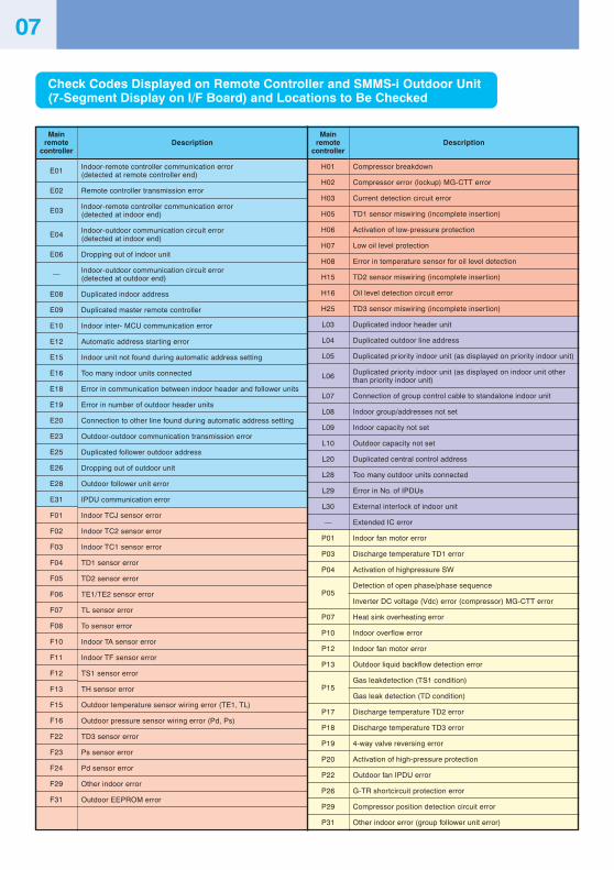
Description
Compressor breakdown
Compressor error (lockup) MG-CTT error
Current detection circuit error
TD1 sensor miswiring (incomplete insertion)
Activation of low-pressure protection
Low oil level protection
Error in temperature sensor for oil level detection
TD2 sensor miswiring (incomplete insertion)
Oil level detection circuit error
TD3 sensor miswiring (incomplete insertion)
Duplicated indoor header unit
Duplicated outdoor line address
Duplicated priority indoor unit (as displayed on priority indoor unit)
Duplicated priority indoor unit (as displayed on indoor unit otherthan priority indoor unit)
Connection of group control cable to standalone indoor unit
Indoor group/addresses not set
Indoor capacity not set
Outdoor capacity not set
Duplicated central control address
Too many outdoor units connected
Error in No. of IPDUs
External interlock of indoor unit
Extended IC error
Indoor fan motor error
Discharge temperature TD1 error
Activation of highpressure SW
Detection of open phase/phase sequence
Inverter DC voltage (Vdc) error (compressor) MG-CTT error
Heat sink overheating error
Indoor overflow error
Indoor fan motor error
Outdoor liquid backflow detection error
Gas leakdetection (TS1 condition)
Gas leak detection (TD condition)
Discharge temperature TD2 error
Discharge temperature TD3 error
4-way valve reversing error
Activation of high-pressure protection
Outdoor fan IPDU error
G-TR shortcircuit protection error
Compressor position detection circuit error
Other indoor error (group follower unit error)
Check Code List
Description
Indoor-remote controller communication error(detected at remote controller end)
Remote controller transmission error
Indoor-remote controller communication error(detected at indoor end)
Indoor-outdoor communication circuit error(detected at indoor end)
Dropping out of indoor unit
Indoor-outdoor communication circuit error(detected at outdoor end)
Duplicated indoor address
Duplicated master remote controller
Indoor inter- MCU communication error
Automatic address starting error
Indoor unit not found during automatic address setting
Too many indoor units connected
Error in communication between indoor header and follower units
Error in number of outdoor header units
Connection to other line found during automatic address setting
Outdoor-outdoor communication transmission error
Duplicated follower outdoor address
Dropping out of outdoor unit
Outdoor follower unit error
IPDU communication error
Indoor TCJ sensor error
Indoor TC2 sensor error
Indoor TC1 sensor error
TD1 sensor error
TD2 sensor error
TE1/TE2 sensor error
TL sensor error
To sensor error
Indoor TA sensor error
Indoor TF sensor error
TS1 sensor error
TH sensor error
Outdoor temperature sensor wiring error (TE1, TL)
Outdoor pressure sensor wiring error (Pd, Ps)
TD3 sensor error
Ps sensor error
Pd sensor error
Other indoor error
Outdoor EEPROM error
Mainremote
controller
H01
H02
H03
H05
H06
H07
H08
H15
H16
H25
L03
L04
L05
L06
L07
L08
L09
L10
L20
L28
L29
L30
—
P01
P03
P04
P05
P07
P10
P12
P13
P15
P17
P18
P19
P20
P22
P26
P29
P31
Mainremote
controller
E01
E02
E03
E04
E06
—
E08
E09
E10
E12
E15
E16
E18
E19
E20
E23
E25
E26
E28
E31
F01
F02
F03
F04
F05
F06
F07
F08
F10
F11
F12
F13
F15
F16
F22
F23
F24
F29
F31
07
Check Codes Displayed on Remote Controller and SMMS-i Outdoor Unit(7-Segment Display on I/F Board) and Locations to Be Checked
Address Setup 08
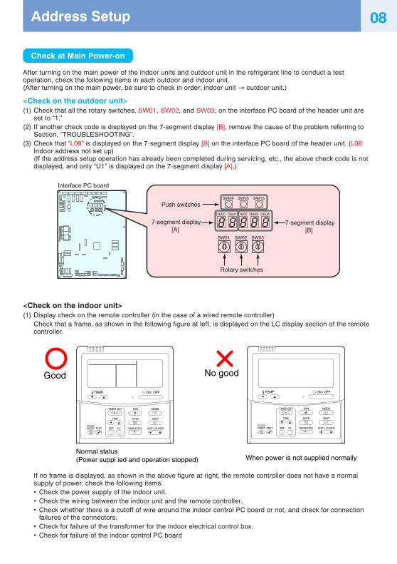
Check at Main Power-on
After turning on the main power of the indoor units and outdoor unit in the refrigerant line to conduct a testoperation, check the following items in each outdoor and indoor unit.(After turning on the main power, be sure to check in order: indoor unit → outdoor unit.)
<Check on the outdoor unit>(1) Check that all the rotary switches, SW01, SW02, and SW03, on the interface PC board of the header unit are
set to “1.”(2) If another check code is displayed on the 7-segment display [B], remove the cause of the problem referring to
Section, “TROUBLESHOOTING”.(3) Check that “L08” is displayed on the 7-segment display [B] on the interface PC board of the header unit. (L08:
Indoor address not set up)(If the address setup operation has already been completed during servicing, etc., the above check code is notdisplayed, and only “U1” is displayed on the 7-segment display [A].)
<Check on the indoor unit>(1) Display check on the remote controller (in the case of a wired remote controller)
Check that a frame, as shown in the following figure at left, is displayed on the LC display section of the remotecontroller.
If no frame is displayed, as shown in the above figure at right, the remote controller does not have a normalsupply of power; check the following items.• Check the power supply of the indoor unit.• Check the wiring between the indoor unit and the remote controller.• Check whether there is a cutoff of wire around the indoor control PC board or not, and check for connection
failures of the connectors.• Check for failure of the transformer for the indoor electrical control box.• Check for failure of the indoor control PC board
Interface PC board
SW01 SW02 SW03
SW04
D600 D601 D602 D603 D604
SW15SW05
Push switches
Rotary switches
7-segment display[A]
7-segment display[B]
Normal status(Power suppl ied and operation stopped) When power is not supplied normally
Good No good
TEMP. ON / OFF
SET
TIME
TESTFILTERRESET CL
SAVE
SWING/FIX
VENT
UNIT LOUVER
TIMER SET MODEFAN
TEMP. ON / OFF
SET
TIME
TESTFILTERRESET CL
SAVE
SWING/FIX
VENT
UNIT LOUVER
TIMER SET MODEFAN
Precautions
(1) Address setup is not performed simply by turning on the power supply.(2) For indoor units, address setup can be done either by manual address setup or by automatic address setup:
Automatic address setup: Setup from SW15 on the interface PC board of the header unitManual address setup: Setup from the wired remote controller.(For details, refer to “Address Setup Procedure.”)
(3) Automatic setup usually takes about 5 minutes per line. In some cases, however, it may take up to 10 minutes.(4) It is unnecessary to operate the air conditioner to achieve address setup.
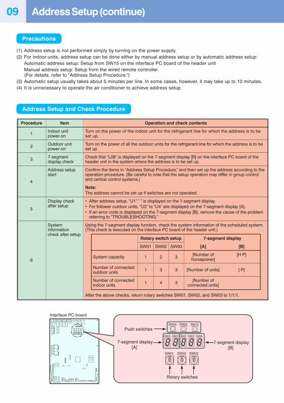
Address Setup and Check Procedure
Interface PC board
SW01 SW02 SW03
SW04
D600 D601 D602 D603 D604
SW15SW05
Push switches
Rotary switches
7-segment display[A]
7-segment display[B]
Address Setup (continue)09
Item
Indoor unitpower-on
Outdoor unitpower-on
7-segmentdisplay check
Address setupstart
Display checkafter setup
Systeminformationcheck after setup
Operation and check contents
Turn on the power of the indoor unit for the refrigerant line for which the address is to beset up.
Turn on the power of all the outdoor units for the refrigerant line for which the address is to beset up.
Check that “L08” is displayed on the 7-segment display [B] on the interface PC board of theheader unit in the system where the address is to be set up.
Confirm the items in “Address Setup Procedure,” and then set up the address according to theoperation procedure. (Be careful to note that the setup operation may differ in group controland central control systems.)
Note:The address cannot be set up if switches are not operated.
• After address setup, “U1” “ ” is displayed on the 7-segment display.• For follower outdoor units, “U2” to “U4” are displayed on the 7-segment display [A].• If an error code is displayed on the 7-segment display [B], remove the cause of the problem
referring to “TROUBLESHOOTING.”
Using the 7-segment display function, check the system information of the scheduled system.(This check is executed on the interface PC board of the header unit.)
System capacity
Number of connectedoutdoor units
Number of connectedindoor units
Rotary switch setup
SW01 SW02 SW03
1 2 3
1 3 3
1 4 3
After the above checks, return rotary switches SW01, SW02, and SW03 to 1/1/1.
Procedure
1
2
3
4
5
6
7-segment display
[A] [B]
[Number of [H P]horsepower]
[Number of units] [ P]
[Number ofconnected units]
10
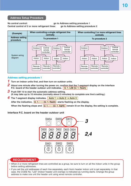
Address Setup Procedure
No central control: go to Address setting procedure 1Central control of 2 or more refrigerant lines: go to Address setting procedure 2
Address setting procedure 1
1 Turn on indoor units first, and then turn on outdoor units.
2 About one minute after turning the power on, confirm that the 7-segment display on the interfaceP.C. board of the header outdoor unit indicates. U. 1. L08 (U. 1. flash)
3 Push SW 15 to start the automatic address setting.(It may take up to 10 minutes (normally about 5 minutes) to complete one line’s setting.)
4 The 7-segment display indicates. Auto 1 →→→→→ Auto 2 →→→→→ Auto 3
After the indication, U. 1. - - - (U. 1. flash) starts flashing on the display.
When the flashing stops and U. 1. - - - (U. 1. light) remain lit on the display, the setting is complete.
Interface P.C. board on the header outdoor unit
(Example) When controlling a single refrigerant linecentrally
When controlling 2 or more refrigerant linescentrally
Address settingprocedure
To procedure 1 To procedure 2
System wiringdiagram
Outdoor
Indoor IndoorIndoor Indoor
OutdoorCentralremote
controller
Centralremote
controller
Centralremote
controller
Remotecontroller
Remotecontroller
Remotecontroller
Remotecontroller
Outdoor
Indoor Indoor Indoor Indoor
Outdoor
Remotecontroller
Remotecontroller
SW04 SW05 SW15
SW01 SW02 SW03
D600 D601 D602 D603 D604
3
2,4
REQUIREMENT• When 2 or more refrigerant lines are controlled as a group, be sure to turn on all the indoor units in the group
before setting addresses.• If you set the unit addresses of each line separately, each line’s header indoor unit is set separately. In that
case, the CODE No. “L03” (Indoor header unit overlap) is indicated as running starts. Change the groupaddress to make one unit the header unit using wired remote controller.
FILE NO. :A11-001
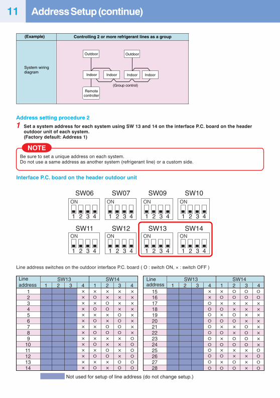
Address setting procedure 2
1 Set a system address for each system using SW 13 and 14 on the interface P.C. board on the headeroutdoor unit of each system.(Factory default: Address 1)
NOTEBe sure to set a unique address on each system.Do not use a same address as another system (refrigerant line) or a custom side.
Interface P.C. board on the header outdoor unit
(Example) Controlling 2 or more refrigerant lines as a group
System wiring diagram
Indoor Indoor IndoorIndoor
OutdoorOutdoor
Remotecontroller
(Group control)
SW06 SW07 SW09 SW10
SW11 SW12 SW13 SW14
1 2 3 4 1 2 3 4 1 2 3 4 1 2 3 4
1 2 3 4 1 2 3 4 1 2 3 4 1 2 3 4
SW13 SW141
123456789
1011121314
××××××××××××××
×O
×O
×O
×O
×O
×O×O
××OO
××OO
××O
O
××
××××OO
OO
××××OO
××××××××O
OO
OOO
2 3 4 1 2 3 4SW13 SW14
11516171819202122232425262728
××O
OO
OO
O
O
OOO
O
O
×O
×O×O×O×O×O
×O
OO
××O
O××O
O××O
O
OO
××××O
OO
O××××
OO
××××××××OO
O
O
2 3 4 1 2 3 4
Not used for setup of line address (do not change setup.)
Lineaddress
Lineaddress
Line address switches on the outdoor interface P.C. board ( O : switch ON, × : switch OFF )
Address Setup (continue)11
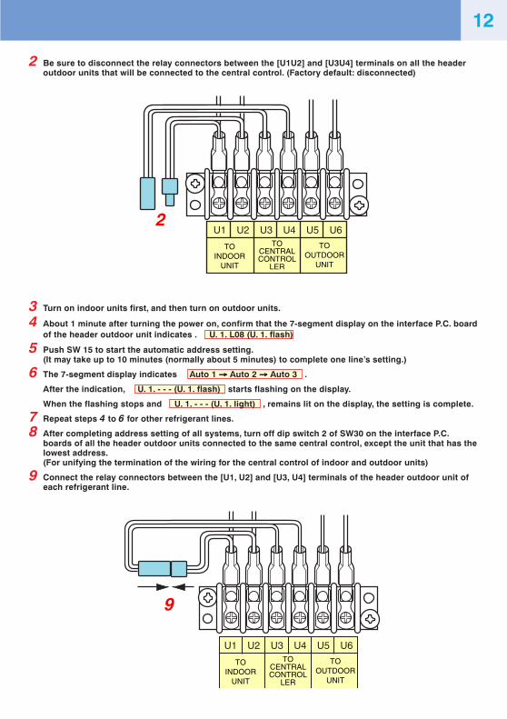
2 Be sure to disconnect the relay connectors between the [U1U2] and [U3U4] terminals on all the headeroutdoor units that will be connected to the central control. (Factory default: disconnected)
3 Turn on indoor units first, and then turn on outdoor units.
4 About 1 minute after turning the power on, confirm that the 7-segment display on the interface P.C. boardof the header outdoor unit indicates . U. 1. L08 (U. 1. flash)
5 Push SW 15 to start the automatic address setting.(It may take up to 10 minutes (normally about 5 minutes) to complete one line’s setting.)
6 The 7-segment display indicates Auto 1 →→→→→ Auto 2 →→→→→ Auto 3 .
After the indication, U. 1. - - - (U. 1. flash) starts flashing on the display.
When the flashing stops and U. 1. - - - (U. 1. light) , remains lit on the display, the setting is complete.
7 Repeat steps 4 to 6 for other refrigerant lines.
8 After completing address setting of all systems, turn off dip switch 2 of SW30 on the interface P.C.boards of all the header outdoor units connected to the same central control, except the unit that has thelowest address.(For unifying the termination of the wiring for the central control of indoor and outdoor units)
9 Connect the relay connectors between the [U1, U2] and [U3, U4] terminals of the header outdoor unit ofeach refrigerant line.
U1 U2 U3 U4 U5 U62
TOINDOOR
UNIT
TOCENTRALCONTROL
LER
TOOUTDOOR
UNIT
U1 U2 U3 U4 U5 U6
9
TOINDOOR
UNIT
TOCENTRALCONTROL
LER
TOOUTDOOR
UNIT
12
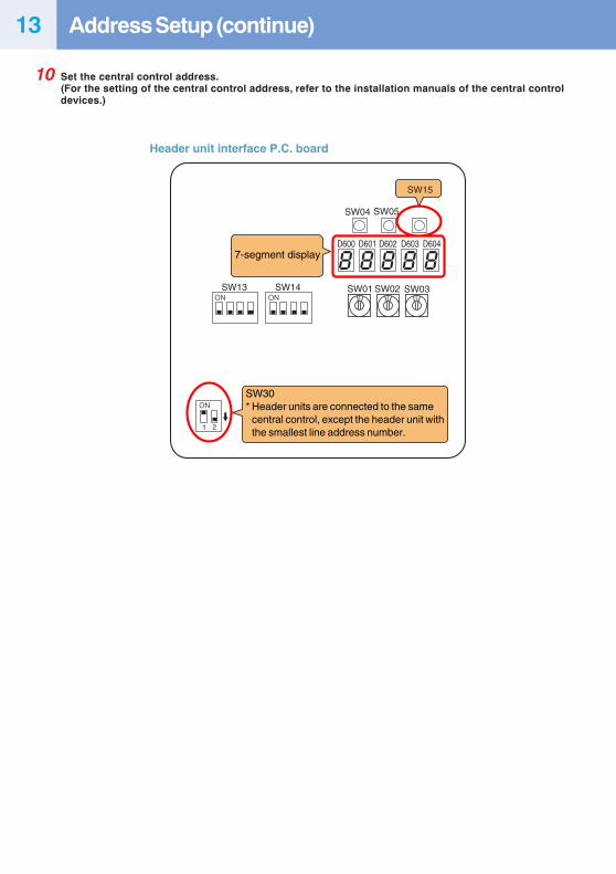
10 Set the central control address.(For the setting of the central control address, refer to the installation manuals of the central controldevices.)
SW15
SW04
1 2
SW13 SW14 SW01 SW02 SW03
D600 D601 D602 D603 D604
SW05
7-segment display
Header unit interface P.C. board
SW30* Header units are connected to the same central control, except the header unit with the smallest line address number.
Address Setup (continue)13
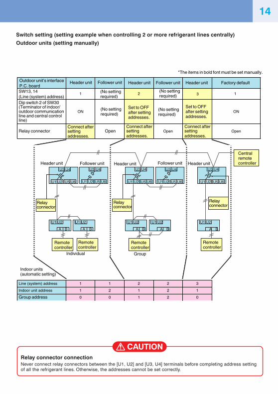
Switch setting (setting example when controlling 2 or more refrigerant lines centrally)
Outdoor units (setting manually)
CAUTIONRelay connector connectionNever connect relay connectors between the [U1, U2] and [U3, U4] terminals before completing address settingof all the refrigerant lines. Otherwise, the addresses cannot be set correctly.
Outdoor unit’s interface P.C. board
Header unit Follower unit Header unit Header unit Follower unit Factory default
SW13, 14(Line (system) address)
1 (No setting required)
(No setting required)
(No setting required)
(No setting required)
2 3 1
Dip switch 2 of SW30 (Terminator of indoor/outdoor communication line and central control line)
ONSet to OFF after setting addresses.
Set to OFF after setting addresses.
ON
Relay connectorConnect after setting addresses.
Connect after setting addresses.
Connect after setting addresses.
Open Open Open
Line (system) address 1 1 2 2 3
Indoor unit address 1 2 1 2 1
Group address 0 0 1 2 0
A
U1 U2
U3 U4 U3 U4 U3 U4 U3 U4 U3 U4
U5 U6 U1 U2 U5 U6 U1 U2 U5 U6 U1 U2 U5 U6 U1 U2
U1 U2 U1 U2 U1 U2 U1 U2 U1 U2
U5 U6
B A B A B A B A B
Central remote controller
Relay connector
Relay connector
Relay connector
Header unit Header unit Header unitFollower unit Follower unit
Remote controller
Remote controller
Remote controller
Remote controller
Individual Group
Indoor units (automatic setting)
*The items in bold font must be set manually.
14
Group address
Individual: 0000Header unit: 0001Follower unit: 0002
(Wiring example for 2 refrigerant lines)Line 1 Line 2
Line 1 Line 2
Outdoor
Indoor 1 Indoor 2Indoor 1
(Remote controller group control)
Indoor 2 Indoor 3
Indoor 1 Indoor 2Indoor 1 Indoor 2 Indoor 3
Line address Indoor address
111
Header
122
Follower Follower Follower Follower
132
212
222
Outdoor
OutdoorOutdoor
(Wiring during manual address setup)
Remotecontroller
Remotecontroller
Remotecontroller
Remotecontroller
Remotecontroller
Remotecontroller
Groupaddress
In the above example, where remote controllers are not yet wired, set the address manually after individually connecting the wired remote controller.
After address setup, return to the original wiring over remote controllers.
In cases of remote controller group control
DN code (CODE No.)Set data
5, 8, 11,146, 9, 12, 15
16
4,7,10,13
3
TEMP. ON / OFF
SET
TIME
TESTFILTERRESET CL
SAVE
SWING/FIX
VENT
UNIT LOUVER
CODE No.
UNIT No.
R.C. No.
TIMER SET MODEFAN
SET DATA SETTING
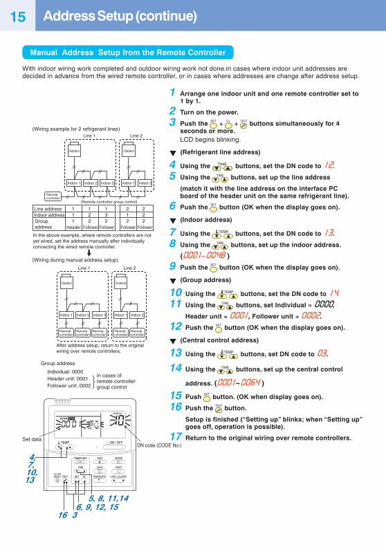
Manual Address Setup from the Remote Controller
With indoor wiring work completed and outdoor wiring work not done.in cases where indoor unit addresses aredecided in advance from the wired remote controller, or in cases where addresses are change after address setup.
1 Arrange one indoor unit and one remote controller set to1 by 1.
2 Turn on the power.
3 Push the SET + CL + TEST buttons simultaneously for 4seconds or more.LCD begins blinking.
(Refrigerant line address)
4 Using the TIME buttons, set the DN code to 12.
5 Using the TIME buttons, set up the line address
(match it with the line address on the interface PCboard of the header unit on the same refrigerant line).
6 Push the SET button (OK when the display goes on).
(Indoor address)
7 Using the TEMP. buttons, set the DN code to 13.
8 Using the TIME buttons, set up the indoor address.
(0001~0048 )
9 Push the SET button (OK when the display goes on).
(Group address)
10 Using the TEMP. buttons, set the DN code to 14.
11 Using the TIME buttons, set Individual = 0000,
Header unit = 0001, Follower unit = 0002.
12 Push the SET button (OK when the display goes on).
(Central control address)
13 Using the TEMP. buttons, set DN code to 03.
14 Using the TIME buttons, set up the central control
address. (0001~0064 )
15 Push SET button. (OK when display goes on).
16 Push the TEST button.
Setup is finished (“Setting up” blinks; when “Setting up”goes off, operation is possible).
17 Return to the original wiring over remote controllers.
Address Setup (continue)15
U3 U4
U1 U2 U5 U6
U1 U2
A B
U3 U4
U1 U2 U5 U6
U1 U2
A B
U3 U4
U1 U2 U5 U6
U1 U2
A B
U3 U4
U1 U2 U5 U6
U1 U2
A B
U3 U4
U1 U2
U1U3
U2U4
U5 U6
U1 U2
A B
Central remote controller
Headerunit
Headerunit
Headerunit
Follower unit Follower unit
Remotecontroller
Remotecontroller
Remotecontroller
Remotecontroller
Indoor units to have their addresses initialized
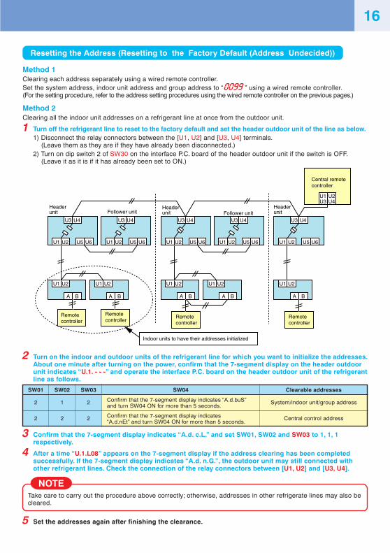
Resetting the Address (Resetting to the Factory Default (Address Undecided))
Method 1Clearing each address separately using a wired remote controller.Set the system address, indoor unit address and group address to “0099 ” using a wired remote controller.(For the setting procedure, refer to the address setting procedures using the wired remote controller on the previous pages.)
Method 2Clearing all the indoor unit addresses on a refrigerant line at once from the outdoor unit.
1 Turn off the refrigerant line to reset to the factory default and set the header outdoor unit of the line as below.1) Disconnect the relay connectors between the [U1, U2] and [U3, U4] terminals.
(Leave them as they are if they have already been disconnected.)2) Turn on dip switch 2 of SW30 on the interface P.C. board of the header outdoor unit if the switch is OFF.
(Leave it as it is if it has already been set to ON.)
3 Confirm that the 7-segment display indicates “A.d. c.L.” and set SW01, SW02 and SW03 to 1, 1, 1respectively.
4 After a time “U.1.L08” appears on the 7-segment display if the address clearing has been completedsuccessfully. If the 7-segment display indicates “A.d. n.G.”, the outdoor unit may still connected withother refrigerant lines. Check the connection of the relay connectors between [U1, U2] and [U3, U4].
NOTETake care to carry out the procedure above correctly; otherwise, addresses in other refrigerate lines may also becleared.
5 Set the addresses again after finishing the clearance.
2 Turn on the indoor and outdoor units of the refrigerant line for which you want to initialize the addresses.About one minute after turning on the power, confirm that the 7-segment display on the header outdoorunit indicates “U.1. - - -” and operate the interface P.C. board on the header outdoor unit of the refrigerantline as follows.
SW01
2
2
SW02
1
2
SW03
2
2
SW04
Confirm that the 7-segment display indicates “A.d.buS”and turn SW04 ON for more than 5 seconds.
Confirm that the 7-segment display indicates“A.d.nEt” and turn SW04 ON for more than 5 seconds.
Clearable addresses
System/indoor unit/group address
Central control address
16
Added Indoor unit
U3 U4
U1 U2 U5 U6
U1 U2
A B
U3 U4
U1 U2 U5 U6
U1 U2
A B
U3 U4
U1 U2 U5 U6
U1 U2
A B
U3 U4
U1 U2 U5 U6
U1 U2
A B
U3 U4
U1 U2
U1U3
U2U4
U5 U6
U1 U2
A B
Central remote controller
Headerunit
Headerunit
Headerunit
Follower unit Follower unit
Remotecontroller
Remotecontroller
Remotecontroller
Remotecontroller
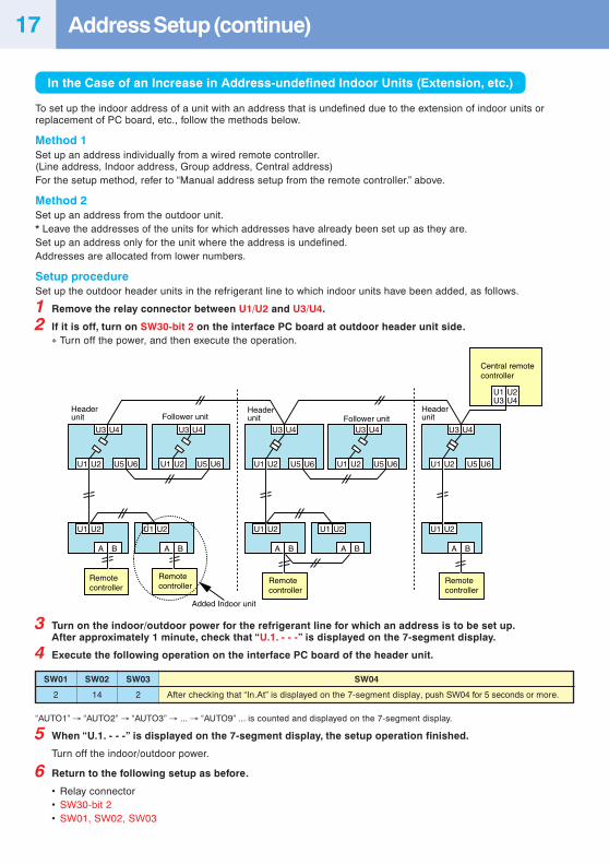
In the Case of an Increase in Address-undefined Indoor Units (Extension, etc.)
To set up the indoor address of a unit with an address that is undefined due to the extension of indoor units orreplacement of PC board, etc., follow the methods below.
Method 1Set up an address individually from a wired remote controller.(Line address, Indoor address, Group address, Central address)For the setup method, refer to “Manual address setup from the remote controller.” above.
Method 2Set up an address from the outdoor unit.* Leave the addresses of the units for which addresses have already been set up as they are.Set up an address only for the unit where the address is undefined.Addresses are allocated from lower numbers.
Setup procedureSet up the outdoor header units in the refrigerant line to which indoor units have been added, as follows.
1 Remove the relay connector between U1/U2 and U3/U4.
2 If it is off, turn on SW30-bit 2 on the interface PC board at outdoor header unit side.∗ Turn off the power, and then execute the operation.
“AUTO1” → “AUTO2” → “AUTO3” → ... → “AUTO9” ... is counted and displayed on the 7-segment display.
5 When “U.1. - - -” is displayed on the 7-segment display, the setup operation finished.
Turn off the indoor/outdoor power.
6 Return to the following setup as before.
• Relay connector• SW30-bit 2• SW01, SW02, SW03
SW01
2
SW02
14
SW03
2
SW04
After checking that “In.At” is displayed on the 7-segment display, push SW04 for 5 seconds or more.
3 Turn on the indoor/outdoor power for the refrigerant line for which an address is to be set up.After approximately 1 minute, check that “U.1. - - -” is displayed on the 7-segment display.
4 Execute the following operation on the interface PC board of the header unit.
Address Setup (continue)17
18
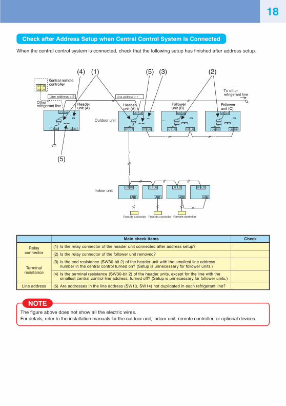
Check after Address Setup when Central Control System Is Connected
When the central control system is connected, check that the following setup has finished after address setup.
NOTEThe figure above does not show all the electric wires.For details, refer to the installation manuals for the outdoor unit, indoor unit, remote controller, or optional devices.
U1 U2
U1 U2 U1 U2 U1 U2 U1 U2
U5 U6
U3 U4
Header unit (A)
Header unit (A)
U1 U2 U5 U6
U3 U4
U1 U2 U5 U6
A B A B A B A B
(5)(4)
(5)
(1) (2)(3)
Other refrigerant line
U1 U2U3 U4
U3 U4
U1 U2 U5 U6
To other refrigerant line
U3 U4
Line address = 2 Line address = 1
entral remote controller
Follower unit (C)
Follower unit (B)
Outdoor unit
Indoor unit
Remote controller Remote controller Remote controller
Relayconnector
Terminalresistance
Line address
Main check items
(1) Is the relay connector of the header unit connected after address setup?
(2) Is the relay connector of the follower unit removed?
(3) Is the end resistance (SW30-bit 2) of the header unit with the smallest line addressnumber in the central control turned on? (Setup is unnecessary for follower units.)
(4) Is the terminal resistance (SW30-bit 2) of the header units, except for the line with thesmallest central control line address, turned off? (Setup is unnecessary for follower units.)
(5) Are addresses in the line address (SW13, SW14) not duplicated in each refrigerant line?
Check
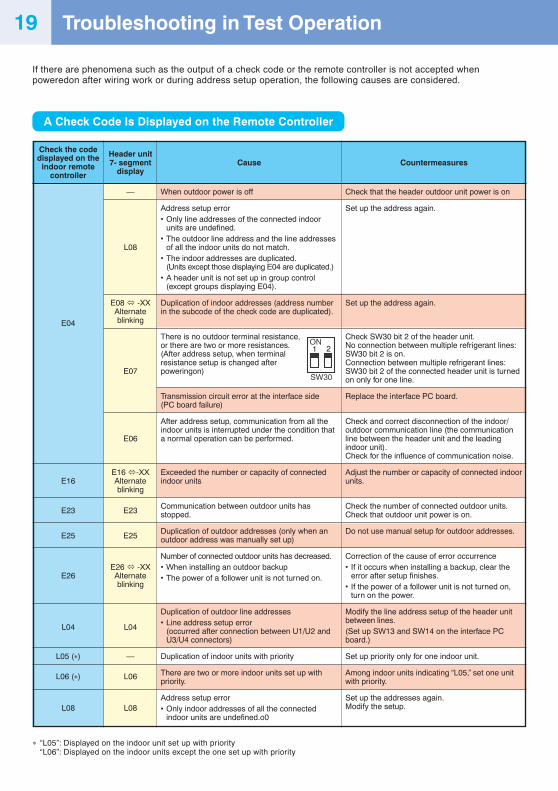
Troubleshooting in Test Operation
If there are phenomena such as the output of a check code or the remote controller is not accepted whenpoweredon after wiring work or during address setup operation, the following causes are considered.
A Check Code Is Displayed on the Remote Controller
Cause
When outdoor power is off
Address setup error• Only line addresses of the connected indoor
units are undefined.• The outdoor line address and the line addresses
of all the indoor units do not match.• The indoor addresses are duplicated.
(Units except those displaying E04 are duplicated.)• A header unit is not set up in group control
(except groups displaying E04).
Duplication of indoor addresses (address numberin the subcode of the check code are duplicated).
There is no outdoor terminal resistance,or there are two or more resistances.(After address setup, when terminalresistance setup is changed afterpoweringon)
Transmission circuit error at the interface side(PC board failure)
After address setup, communication from all theindoor units is interrupted under the condition thata normal operation can be performed.
Exceeded the number or capacity of connectedindoor units
Communication between outdoor units hasstopped.
Duplication of outdoor addresses (only when anoutdoor address was manually set up)
Number of connected outdoor units has decreased.• When installing an outdoor backup• The power of a follower unit is not turned on.
Duplication of outdoor line addresses• Line address setup error
(occurred after connection between U1/U2 andU3/U4 connectors)
Duplication of indoor units with priority
There are two or more indoor units set up withpriority.
Address setup error• Only indoor addresses of all the connected
indoor units are undefined.o0
Countermeasures
Check that the header outdoor unit power is on
Set up the address again.
Set up the address again.
Check SW30 bit 2 of the header unit.No connection between multiple refrigerant lines:SW30 bit 2 is on.Connection between multiple refrigerant lines:SW30 bit 2 of the connected header unit is turnedon only for one line.
Replace the interface PC board.
Check and correct disconnection of the indoor/outdoor communication line (the communicationline between the header unit and the leadingindoor unit).Check for the influence of communication noise.
Adjust the number or capacity of connected indoorunits.
Check the number of connected outdoor units.Check that outdoor unit power is on.
Do not use manual setup for outdoor addresses.
Correction of the cause of error occurrence• If it occurs when installing a backup, clear the
error after setup finishes.• If the power of a follower unit is not turned on,
turn on the power.
Modify the line address setup of the header unitbetween lines.(Set up SW13 and SW14 on the interface PCboard.)
Set up priority only for one indoor unit.
Among indoor units indicating “L05,” set one unitwith priority.
Set up the addresses again.Modify the setup.
∗ “L05”: Displayed on the indoor unit set up with priority“L06”: Displayed on the indoor units except the one set up with priority
ON
SW30
1 2
Check the codedisplayed on the
indoor remotecontroller
E04
E16
E23
E25
E26
L04
L05 (∗)
L06 (∗)
L08
Header unit7- segment
display
—
L08
E08 -XXAlternateblinking
E07
E06
E16 -XXAlternateblinking
E23
E25
E26 -XXAlternateblinking
L04
—
L06
L08
19
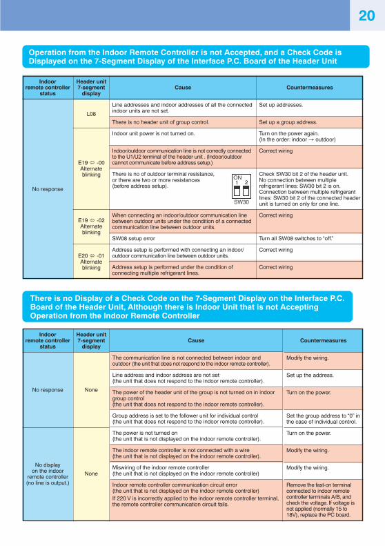
Operation from the Indoor Remote Controller is not Accepted, and a Check Code isDisplayed on the 7-Segment Display of the Interface P.C. Board of the Header Unit
Indoorremote controller
status
No response
Header unit7-segment
display
L08
E19 -00Alternateblinking
E19 -02Alternateblinking
E20 -01Alternateblinking
Cause
Line addresses and indoor addresses of all the connectedindoor units are not set.
There is no header unit of group control.
Indoor unit power is not turned on.
Indoor/outdoor communication line is not correctly connectedto the U1/U2 terminal of the header unit . (Indoor/outdoorcannot communicate before address setup.)
There is no of outdoor terminal resistance,or there are two or more resistances(before address setup).
When connecting an indoor/outdoor communication linebetween outdoor units under the condition of a connectedcommunication line between outdoor units.
SW08 setup error
Address setup is performed with connecting an indoor/outdoor communication line between outdoor units.
Address setup is performed under the condition ofconnecting multiple refrigerant lines.
Countermeasures
Set up addresses.
Set up a group address.
Turn on the power again.(In the order: indoor → outdoor)
Correct wiring
Check SW30 bit 2 of the header unit.No connection between multiplerefrigerant lines: SW30 bit 2 is on.Connection between multiple refrigerantlines: SW30 bit 2 of the connected headerunit is turned on only for one line.
Correct wiring
Turn all SW08 switches to “off.”
Correct wiring
Correct wiring
There is no Display of a Check Code on the 7-Segment Display on the Interface P.C.Board of the Header Unit, Although there is Indoor Unit that is not AcceptingOperation from the Indoor Remote Controller
Indoorremote controller
status
No response
No displayon the indoor
remote controller(no line is output.)
Header unit7-segment
display
None
None
Countermeasures
Modify the wiring.
Set up the address.
Turn on the power.
Set the group address to “0” inthe case of individual control.
Turn on the power.
Modify the wiring.
Modify the wiring.
Remove the fast-on terminalconnected to indoor remotecontroller terminals A/B, andcheck the voltage. If voltage isnot applied (normally 15 to18V), replace the PC board.
ON
SW30
1 2
20
Cause
The communication line is not connected between indoor andoutdoor (the unit that does not respond to the indoor remote controller).
Line address and indoor address are not set(the unit that does not respond to the indoor remote controller).
The power of the header unit of the group is not turned on in indoorgroup control(the unit that does not respond to the indoor remote controller).
Group address is set to the follower unit for individual control(the unit that does not respond to the indoor remote controller).
The power is not turned on(the unit that is not displayed on the indoor remote controller).
The indoor remote controller is not connected with a wire(the unit that is not displayed on the indoor remote controller).
Miswiring of the indoor remote controller(the unit that is not displayed on the indoor remote controller)
Indoor remote controller communication circuit error(the unit that is not displayed on the indoor remote controller)If 220 V is incorrectly applied to the indoor remote controller terminal,the remote controller communication circuit fails.
Countermeasures
After modification of wiring, set up the addresses againand check the number of connected outdoor units.
After modification of wiring, set up the addresses againand check the number of connected indoor units.
Using the main indoor remote controller connected to agroup, start a test operation, specify the unit that is notoperating (the unit not connected to the group), and thencheck the wiring.
Using the main indoor remote controller connected to agroup, start a test operation and then specify the unitthat is not operating (the unit not connected to the group).Remove the fast-on terminal connected to remotecontroller terminals A/B, and check the voltage.If voltage is not applied (normally 15 to18 V), replace thePC board.
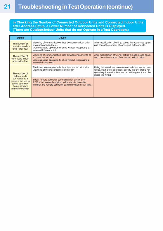
Status
The number ofconnected outdoor
units is too few.
The number ofconnected indoorunits is too few.
The number ofoutdoor units
connected to agroup is too few ingroup operationfrom an indoor
remote controller.
In Checking the Number of Connected Outdoor Units and Connected Indoor Unitsafter Address Setup, a Lower Number of Connected Units is Displayed.(There are Outdoor/Indoor Units that do not Operate in a Test Operation.)
Troubleshooting in Test Operation (continue)21
Cause
Miswiring of communication lines between outdoor unitsor an unconnected wire .(Address setup operation finished without recognizing amiswired follower unit.)
Miswiring of communication lines between indoor units oran unconnected wire .(Address setup operation finished without recognizing amiswired indoor unit.)
The indoor remote controller is not connected with wire.Miswiring of the indoor remote controller
Indoor remote controller communication circuit errorIf 220 V is incorrectly applied to the remote controllerterminal, the remote controller communication circuit fails.
Monitoring Function of Remote Controller Switch
CODE No.00
010203040506
080A0B0C0D
CODE No.U1 U2 U3 U410 20 30 4011 21 31 4112 22 32 42
13 23 33 4314 24 34 –15 25 35 4516 26 36 4617 27 37 –18 28 38 48
19 29 39 491A 2A 3A 4A1B 2B 3B –1C 2C 3C 4C1D 2D 3D 4D1E 2E 3E –1F 2F 3F 4F
CODE No.U1 U2 U3 U450 60 70 8051 61 71 81
52 62 72 –53 63 73 8354 64 74 8455 65 75 85
56 66 76 –
57 67 77 87
58 – – –
59 – – –
5A – – –
5B – – –
5F 6F 7F 8F
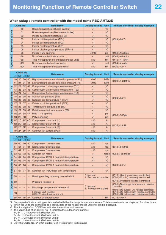
Data nameRoom temperature (During control)
Room temperature (Remote controller)Indoor suction temperature (TA)Indoor coil temperature (TCJ)Indoor coil temperature (TC2)Indoor coil temperature (TC1)Indoor discharge temperature (TF) ∗1
Indoor PMV openingNo. of connected indoor unitsTotal horsepower of connected indoor unitsNo. of connected outdoor unitsTotal horsepower of outdoor units
Data name
High-pressure sensor detention pressure (Pd)Low-pressure sensor detention pressure (Ps)Compressor 1 discharge temperature (Td1)
Compressor 2 discharge temperature (Td2)Compressor 3 discharge temperature (Td3)Suction temperature (TS)Outdoor coil temperature 1 (TE1)Outdoor coil temperature 2 (TE2)Temperature at liquid side (TL)
Outside ambient temperature (TO)PMV1 + 2 openingPMV4 openingCompressor 1 current (I1)Compressor 2 current (I2)Compressor 3 current (I3)Outdoor fan current (IFan)
Data name
Compressor 1 revolutionsCompressor 2 revolutions
Compressor 3 revolutionsOutdoor fan modeCompressor IPDU 1 heat sink temperatureCompressor IPDU 2 heat sink temperature
Compressor IPDU 3 heat sink temperature
Outdoor fan IPDU heat sink temperature
Heating/cooling recovery controlled ∗5
Pressure release ∗5
Discharge temperature release ∗5
Follower unit release(U2/U2/U4 outdoor units) ∗5Outdoor unit horsepower
Display format Unit×1 °C
×1 °C×1 °C×1 °C×1 °C×1 °C×1 °C
×1/10 pls×1 unit
×10 HP×1 unit
×10 HP
Display format Unit
×100 MPa×100 MPa
×1 °C
×1 °C×1 °C×1 °C×1 °C×1 °C×1 °C
×1 °C×1 pls×1 pls
×10 A×10 A×10 A×10 A
Display format Unit
×10 rps×10 rps
×10 rps×1 mode×1 °C×1 °C
×1 °C
×1 °C
0: Normal1: Recovery controlled
0: Normal1: Release controlled
×1 HP
Remote controller display example
[0024]=24°C
[0150]=1500pls[0048]=48 units[0415]=41.5HP[0004]=4 units[0420]=42HP
Remote controller display example
[0123]=1.23MPa
[0024]=24°C
[0500]=500pls
[0135]=13.5A
Remote controller display example
[0642]=64.2rps
[0058]= 58 mode
[0024]=24°C
[0010]=Heating recovery controlled[0001]=Cooling recovery controlled[0010]=Pressure release controlled[0001]=Discharge temperature releasecontrolled[0100]=U2 outdoor unit release controlled[0010]=U3 outdoor unit release controlled[0001]=U4 outdoor unit release controlled[0016]=16HP
Ou
tdo
or
un
it in
div
idu
al d
ata
1 ∗∗∗∗ ∗3
*1 Only a part of indoor unit types is installed with the discharge temperature sensor. This temperature is not displayed for other types.∗2 When the units are connected to a group, data of the header indoor unit only can be displayed.∗3 The first digit of an CODE No. indicates the outdoor unit number.∗4 The upper digit of an CODE No. -4 indicates the outdoor unit number.
1∗, 5∗ ... U1 outdoor unit (Header unit)2∗, 6∗ ... U2 outdoor unit (Follower unit 1)3∗, 7∗ ... U3 outdoor unit (Follower unit 2)4∗, 8∗ ... U4 outdoor unit (Follower unit 3)
∗5 Only the CODE No. 5* of U1 outdoor unit (Header unit) is displayed.
Sys
tem
dat
aIn
do
or
un
it d
ata ∗∗∗∗ ∗2
Ou
tdo
or
un
it in
div
idu
al d
ata
2 ∗∗∗∗ ∗4
22
When usiug a remote comtroller with the model name RBC-AMT32E
NOTE(1) When setting the line address from the remote controller, do not use addresses 29 and 30.
Addresses 29 and 30 cannot be set up on the outdoor unit. If they are incorrectly used, the code “E04”(indoor/outdoor communication circuit error) is output.
(2) When manual address setup has been done from a remote controller, and central control over refrigerantlines is to be done, setup the header unit of each line as follows:• Using SW13 and SW14 on the interface PC board of the header unit of each line, setup the line address
for each line.• Except for the line with the smallest line address number, set SW03-bit 2 to “off” for the interface PC board
of the header unit of lines connected to the same central control (put the resistance of the end terminals ofthe central control line, indoors and outdoors, into one).
• Connect the relay connector between U1/U2 and U3/U4 of the header unit for each refrigerant line.• After that, set up the central control address.
(For central control address setup, refer to the installation manual of the central control devices.)
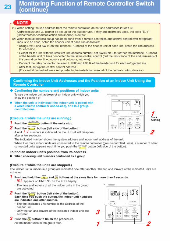
Confirming the Indoor Unit Addresses and the Position of an Indoor Unit Using theRemote Controller
Confirming the numbers and positions of indoor units
1
2
3
1 2
1
TEMP. ON / OFF
SET
TIME
TESTFILTERRESET CL
SAVE
SWING/FIX
VENT
UNIT LOUVER
CODE No.
C
UNIT No.
TIMER SET MODEFAN
TEMP. ON / OFF
SET
TIME
TESTFILTERRESET CL
SAVE
SWING/FIX
VENT
UNIT LOUVER
CODE No.
UNIT No.
R.C. No.
TIMER SET MODEFAN
SET DATA SETTING
Starsrunning
To see the indoor unit address of an indoor unit which youknow the position of
When the unit is individual (the indoor unit is paired witha wired remote controller one-to-one), or it is a group-controlled one.
(Execute it while the units are running.)
1 Push the ON / OFF
button if the units stop.
2 Push the UNIT LOUVER
button (left side of the button).A unit 1-1 numbers is indicated on the LCD (it will disappearafter a few seconds).The indicated number shows the system address and indoor unit address of the unit.When 2 or more indoor units are connected to the remote controller (group-controlled units), a number of otherconnected units appears each time you push the UNIT LOUVER button (left side of the button).
To find an indoor unit’s position from its addressWhen checking unit numbers controlled as a group
(Execute it while the units are stopped.)The indoor unit numbers in a group are indicated one after another. The fan and louvers of the indicated units areactivated.
1 Push and hold the VENT
and TEST
buttons at the same time for more than 4 seconds.• appears on UNIT No. on the LCD display.
• The fans and louvers of all the indoor units in the groupare activated.
2 Push the UNIT LOUVER
button (left side of the button).Each time you push the button, the indoor unit numbersare indicated one after another.• The first-indicated unit number is the address of the
header unit.• Only the fan and louvers of the indicated indoor unit are
activated.
3 Push the TEST
button to finish the procedure.All the indoor units in the group stop.
Monitoring Function of Remote Controller Switch(continue)23
24
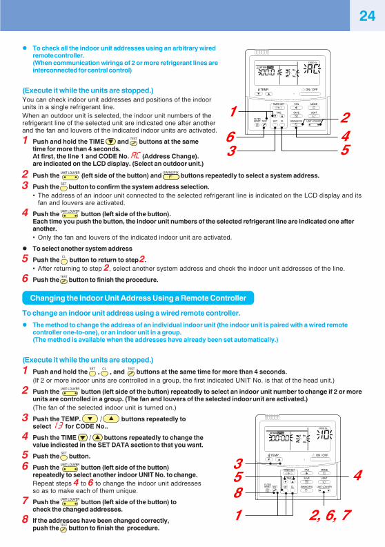
� To check all the indoor unit addresses using an arbitrary wiredremote controller.(When communication wirings of 2 or more refrigerant lines areinterconnected for central control)
(Execute it while the units are stopped.)You can check indoor unit addresses and positions of the indoorunits in a single refrigerant line.When an outdoor unit is selected, the indoor unit numbers of therefrigerant line of the selected unit are indicated one after anotherand the fan and louvers of the indicated indoor units are activated.
1 Push and hold the TIME and TEST
buttons at the sametime for more than 4 seconds.At first, the line 1 and CODE No. �� (Address Change).are indicated on the LCD display. (Select an outdoor unit.)
358
1
4
2, 6, 7
TEMP. ON / OFF
SET
TIME
TESTFILTERRESET CL
SAVE
SWING/FIX
VENT
UNIT LOUVER
CODE No.
UNIT No.
R.C. No.
TIMER SET MODEFAN
SET DATA SETTING
56
1
342
TEMP. ON / OFF
SET
TIME
TESTFILTERRESET CL
SAVE
SWING/FIX
VENT
UNIT LOUVER
CODE No.
UNIT No.
R.C. No.
TIMER SET MODEFAN
SET DATA SETTING
2 Push the UNIT LOUVER
(left side of the button) and SWING/FIX
buttons repeatedly to select a system address.
3 Push the SET
button to confirm the system address selection.• The address of an indoor unit connected to the selected refrigerant line is indicated on the LCD display and its
fan and louvers are activated.
4 Push the UNIT LOUVER
button (left side of the button).Each time you push the button, the indoor unit numbers of the selected refrigerant line are indicated one afteranother.• Only the fan and louvers of the indicated indoor unit are activated.
� To select another system address
5 Push the CL
button to return to step 2.• After returning to step 2, select another system address and check the indoor unit addresses of the line.
6 Push the TEST
button to finish the procedure.
Changing the Indoor Unit Address Using a Remote Controller
To change an indoor unit address using a wired remote controller.
� The method to change the address of an individual indoor unit (the indoor unit is paired with a wired remotecontroller one-to-one), or an indoor unit in a group.(The method is available when the addresses have already been set automatically.)
(Execute it while the units are stopped.)
1 Push and hold the SET
, CL
, and TEST
buttons at the same time for more than 4 seconds.(If 2 or more indoor units are controlled in a group, the first indicated UNIT No. is that of the head unit.)
2 Push the UNIT LOUVER
button (left side of the button) repeatedly to select an indoor unit number to change if 2 or moreunits are controlled in a group. (The fan and louvers of the selected indoor unit are activated.)(The fan of the selected indoor unit is turned on.)
3 Push the TEMP. / buttons repeatedly toselect �� for CODE No..
4 Push the TIME / buttons repeatedly to change thevalue indicated in the SET DATA section to that you want.
5 Push the SET
button.
6 Push the UNIT LOUVER
button (left side of the button)repeatedly to select another indoor UNIT No. to change.Repeat steps 4 to 6 to change the indoor unit addressesso as to make each of them unique.
7 Push the UNIT LOUVER
button (left side of the button) tocheck the changed addresses.
8 If the addresses have been changed correctly,push the
TEST button to finish the procedure.
25
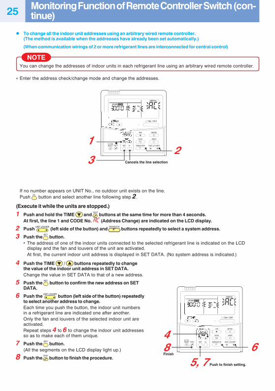
� To change all the indoor unit addresses using an arbitrary wired remote controller.(The method is available when the addresses have already been set automatically.)
(When communication wirings of 2 or more refrigerant lines are interconnected for central control)
NOTEYou can change the addresses of indoor units in each refrigerant line using an arbitrary wired remote controller.
∗ Enter the address check/change mode and change the addresses.
2
4
1
3
85, 7
6
ON / OFF
SETTESTFILTERRESET CL
SAVE
SWING/FIX
VENT
UNIT LOUVER
CODE No.
UNIT
R.C. No.
No.
MODEFAN
SET DATA SETTING
ON / OFF
SETTESTFILTERRESET CL
SAVE
SWING/FIX
VENT
UNIT LOUVER
CODE No.
UNIT
R.C.R C No.
No.
MODEFAN
SET DATA SETTING
Cancels the line selection
Push to finish setting.
Finish
If no number appears on UNIT No., no outdoor unit exists on the line.Push
CL button and select another line following step 2.
(Execute it while the units are stopped.)
1 Push and hold the TIME and TEST
buttons at the same time for more than 4 seconds.At first, the line 1 and CODE No. �� (Address Change) are indicated on the LCD display.
2 Push UNIT LOUVER
(left side of the button) and SWING/FIX
buttons repeatedly to select a system address.
3 Push the SET
button.• The address of one of the indoor units connected to the selected refrigerant line is indicated on the LCD
display and the fan and louvers of the unit are activated.At first, the current indoor unit address is displayed in SET DATA. (No system address is indicated.)
4 Push the TIME / buttons repeatedly to changethe value of the indoor unit address in SET DATA.Change the value in SET DATA to that of a new address.
5 Push the SET
button to confirm the new address on SETDATA.
6 Push the UNIT LOUVER
button (left side of the button) repeatedlyto select another address to change.Each time you push the button, the indoor unit numbersin a refrigerant line are indicated one after another.Only the fan and louvers of the selected indoor unit areactivated.Repeat steps 4 to 6 to change the indoor unit addressesso as to make each of them unique.
7 Push the SET
button.(All the segments on the LCD display light up.)
8 Push the TEST
button to finish the procedure.
Monitoring Function of Remote Controller Switch (con-tinue)
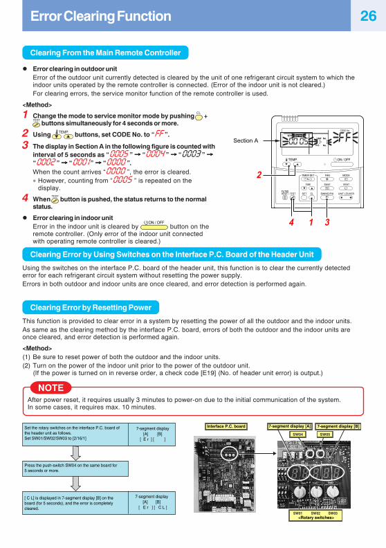
26Error Clearing Function
Clearing From the Main Remote Controller
� Error clearing in outdoor unitError of the outdoor unit currently detected is cleared by the unit of one refrigerant circuit system to which theindoor units operated by the remote controller is connected. (Error of the indoor unit is not cleared.)For clearing errors, the service monitor function of the remote controller is used.
<Method>
TEMP. ON / OFF
SET
TIME
TESTFILTERRESET CL
SAVE
SWING/FIX
VENT
UNIT LOUVER
CODE No.
UNIT No.
No.R.C.
TIMER SET MODEFAN
SET DATA SETTING
1 34
2
Section A
7-segment display[A] [B]
[ E r ] [ ]
7-segment display[A] [B]
[ E r ] [ C L ]
Set the rotary switches on the interface P.C. board of the header unit as follows.Set SW01/SW02/SW03 to [2/16/1]
Press the push-switch SW04 on the same board for 5 seconds or more.
[ C L] is displayed in 7-segment display [B] on the board (for 5 seconds), and the error is completely cleared.
Interface P.C. board
SW04 SW05
SW02 SW03SW01
7-segment display [A] 7-segment display [B]
<Rotary switches>
1 Change the mode to service monitor mode by pushing CL
+TEST
buttons simultaneously for 4 seconds or more.
2 Using TEMP. buttons, set CODE No. to “���”.
3 The display in Section A in the following figure is counted withinterval of 5 seconds as “�����” →→→→→ “�����” →→→→→ “�����” →→→→→“�����” →→→→→ “���” →→→→→ “�����”.When the count arrives “�����”, the error is cleared.∗ However, counting from “�����” is repeated on the
display.
4 When TEST
button is pushed, the status returns to the normalstatus.
� Error clearing in indoor unitError in the indoor unit is cleared by
ON / OFF button on the
remote controller. (Only error of the indoor unit connectedwith operating remote controller is cleared.)
Clearing Error by Using Switches on the Interface P.C. Board of the Header Unit
Using the switches on the interface P.C. board of the header unit, this function is to clear the currently detectederror for each refrigerant circuit system without resetting the power supply.Errors in both outdoor and indoor units are once cleared, and error detection is performed again.
Clearing Error by Resetting Power
This function is provided to clear error in a system by resetting the power of all the outdoor and the indoor units.As same as the clearing method by the interface P.C. board, errors of both the outdoor and the indoor units areonce cleared, and error detection is performed again.
<Method>(1) Be sure to reset power of both the outdoor and the indoor units.(2) Turn on the power of the indoor unit prior to the power of the outdoor unit.
(If the power is turned on in reverse order, a check code [E19] (No. of header unit error) is output.)
NOTEAfter power reset, it requires usually 3 minutes to power-on due to the initial communication of the system.In some cases, it requires max. 10 minutes.
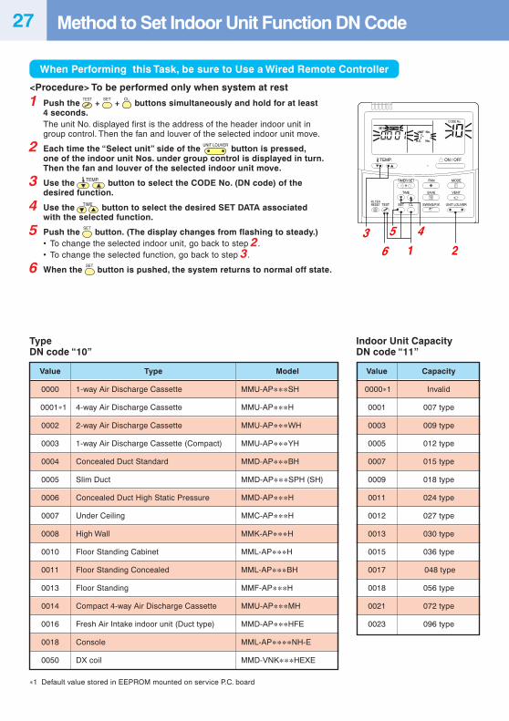
27 Method to Set Indoor Unit Function DN Code
When Performing this Task, be sure to Use a Wired Remote Controller
5 4
63
TEMP. ON / OFF
SET
TIME
TESTFILTERRESET CL
SAVE
SWING/FIX
VENT
UNIT LOUVER
CODE No.
UNIT No.
No.R.C.
TIMER SET MODEFAN
SET DATA SETTING
21
<Procedure> To be performed only when system at rest
1 Push the TEST
+ SET
+ CL
buttons simultaneously and hold for at least4 seconds.The unit No. displayed first is the address of the header indoor unit ingroup control. Then the fan and louver of the selected indoor unit move.
2 Each time the “Select unit” side of the UNIT LOUVER
button is pressed,one of the indoor unit Nos. under group control is displayed in turn.Then the fan and louver of the selected indoor unit move.
3 Use the TEMP. button to select the CODE No. (DN code) of thedesired function.
4 Use the TIME button to select the desired SET DATA associatedwith the selected function.
5 Push the SET
button. (The display changes from flashing to steady.)• To change the selected indoor unit, go back to step 2.• To change the selected function, go back to step 3.
6 When the SET
button is pushed, the system returns to normal off state.
TypeDN code “10”
∗1 Default value stored in EEPROM mounted on service P.C. board
Indoor Unit CapacityDN code “11”
Value
0000
0001∗1
0002
0003
0004
0005
0006
0007
0008
0010
0011
0013
0014
0016
0018
0050
Type
1-way Air Discharge Cassette
4-way Air Discharge Cassette
2-way Air Discharge Cassette
1-way Air Discharge Cassette (Compact)
Concealed Duct Standard
Slim Duct
Concealed Duct High Static Pressure
Under Ceiling
High Wall
Floor Standing Cabinet
Floor Standing Concealed
Floor Standing
Compact 4-way Air Discharge Cassette
Fresh Air Intake indoor unit (Duct type)
Console
DX coil
Model
MMU-AP∗∗∗SH
MMU-AP∗∗∗H
MMU-AP∗∗∗WH
MMU-AP∗∗∗YH
MMD-AP∗∗∗BH
MMD-AP∗∗∗SPH (SH)
MMD-AP∗∗∗H
MMC-AP∗∗∗H
MMK-AP∗∗∗H
MML-AP∗∗∗H
MML-AP∗∗∗BH
MMF-AP∗∗∗H
MMU-AP∗∗∗MH
MMD-AP∗∗∗HFE
MML-AP∗∗∗∗NH-E
MMD-VNK∗∗∗HEXE
Value
0000∗1
0001
0003
0005
0007
0009
0011
0012
0013
0015
0017
0018
0021
0023
Capacity
Invalid
007 type
009 type
012 type
015 type
018 type
024 type
027 type
030 type
036 type
048 type
056 type
072 type
096 type
28
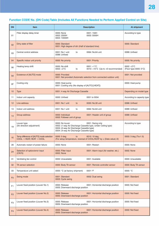
Function CODE No. (DN Code) Table (Includes All Functions Needed to Perform Applied Control on Site)
DN
01
02
03
04
06
0d
0F
10
11
12
13
14
19
1E
28
2A
31
32
33
F0
F1
F2
F3
F4
Item
Filter display delay timer
Dirty state of filter
Central control address
Specific indoor unit priority
Heating temp shift
Existence of [AUTO] mode
Cooling only
Type
Indoor unit capacity
Line address
Indoor unit address
Group address
Louver type(Air direction adjustment)
Temp difference of [AUTO] mode selectionCOOL → HEAT, HEAT → COOL
Automatic restart of power failure
Selection of option/error input(CN70)
Ventilating fan control
TA sensor selection
Temperature unit select
Swing mode
Louver fixed position (Louver No.1)
Louver fixed position (Louver No.2)
Louver fixed position (Louver No.3)
Louver fixed position (Louver No.4)
Description
0000: None 0001: 150H0002: 2500H 0003: 5000H0004: 10000H
0000: Standard0001: High degree of dirt (Half of standard time)
0001: No.1 unit to 0064: No.64 unit0099: Unfixed
0000: No priority 0001: Priority
0000: No shift 0001: +1°C0002: +2°C to 0010: +10°C (Up to +6 recommended)
0000: Provided0001: Not provided (Automatic selection from connected outdoor unit)
0000: Heat pump0001: Cooling only (No display of [AUTO] [HEAT])
0001: 4-way Air Discharge Cassette
0000: Unfixed 0001 to 0034
0001: No.1 unit to 0030: No.30 unit
0001: No.1 unit to 0064: No.64 unit
0000: Individual 0001: Header unit of group0002: Follower unit of group
0000: No louver 0001: Swing only0002: (1-way Air Discharge Cassette type, Under Ceiling type)0003: (2-way Air Discharge Cassette type)0004: (4-way Air Discharge Cassette type)
0000: 0 deg to 0010: 10 deg(For setup temperature, reversal of COOL/HEAT by ± (Data value) /2)
0000: None 0001: Restart
0000: Filter input 0001: Alarm input (Air washer, etc.)0002: None
0000: Unavailable 0001: Available
0000: Body TA sensor 0001: Remote controller sensor
0000: °C (at factory shipment) 0001:°F
0001: Standard 0002: Dual swing0003: Cycle swing
0000: Release 0001: Horizontal discharge position0005: Downward discharge position
0000: Release 0001: Horizontal discharge position0005: Downward discharge position
0000: Release 0001: Horizontal discharge position0005: Downward discharge position
0000: Release 0001: Horizontal discharge position0005: Downward discharge position
At shipment
According to type
0000: Standard
0099: Unfixed
0000: No priority
0002: +2°C(Floor type 0000: 0°C)
0001: Not provided
0000: Heat pump
Depending on model type
According to capacity type
0099: Unfixed
0099: Unfixed
0099: Unfixed
According to type
0003: 3 deg (Ts±1.5)
0000: None
0002: None
0000: Unavailable
0000: Body TA sensor
0000: °C
0001: Standard
0000: Not fixed
0000: Not fixed
0000: Not fixed
0000: Not fixed
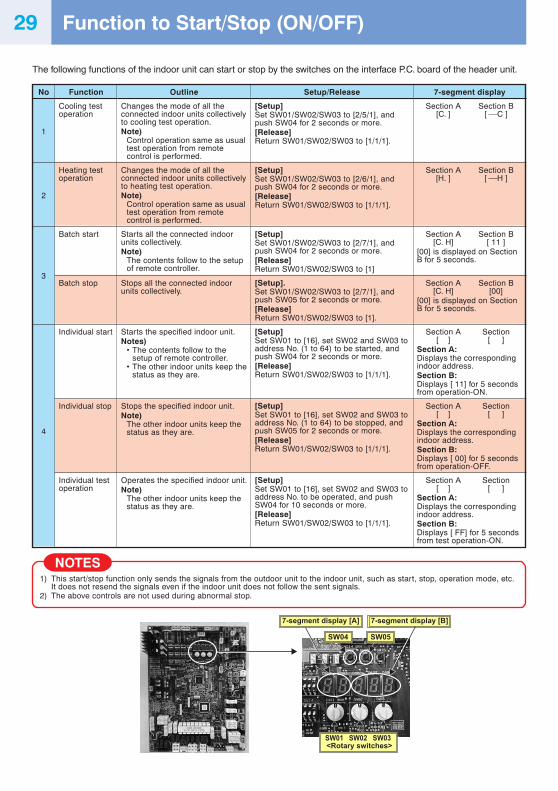
Function to Start/Stop (ON/OFF)29
The following functions of the indoor unit can start or stop by the switches on the interface P.C. board of the header unit.
No
1
2
3
4
Function
Cooling testoperation
Heating testoperation
Batch start
Batch stop
Individual start
Individual stop
Individual testoperation
Outline
Changes the mode of all theconnected indoor units collectivelyto cooling test operation.Note)
Control operation same as usualtest operation from remotecontrol is performed.
Changes the mode of all theconnected indoor units collectivelyto heating test operation.Note)
Control operation same as usualtest operation from remotecontrol is performed.
Starts all the connected indoorunits collectively.Note)
The contents follow to the setupof remote controller.
Stops all the connected indoorunits collectively.
Starts the specified indoor unit.Notes)
• The contents follow to thesetup of remote controller.
• The other indoor units keep thestatus as they are.
Stops the specified indoor unit.Note)
The other indoor units keep thestatus as they are.
Operates the specified indoor unit.Note)
The other indoor units keep thestatus as they are.
Setup/Release
[Setup]Set SW01/SW02/SW03 to [2/5/1], andpush SW04 for 2 seconds or more.[Release]Return SW01/SW02/SW03 to [1/1/1].
[Setup]Set SW01/SW02/SW03 to [2/6/1], andpush SW04 for 2 seconds or more.[Release]Return SW01/SW02/SW03 to [1/1/1].
[Setup]Set SW01/SW02/SW03 to [2/7/1], andpush SW04 for 2 seconds or more.[Release]Return SW01/SW02/SW03 to [1]
[Setup].Set SW01/SW02/SW03 to [2/7/1], andpush SW05 for 2 seconds or more.[Release]Return SW01/SW02/SW03 to [1].
[Setup]Set SW01 to [16], set SW02 and SW03 toaddress No. (1 to 64) to be started, andpush SW04 for 2 seconds or more.[Release]Return SW01/SW02/SW03 to [1/1/1].
[Setup]Set SW01 to [16], set SW02 and SW03 toaddress No. (1 to 64) to be stopped, andpush SW05 for 2 seconds or more.[Release]Return SW01/SW02/SW03 to [1/1/1].
[Setup]Set SW01 to [16], set SW02 and SW03 toaddress No. to be operated, and pushSW04 for 10 seconds or more.[Release]Return SW01/SW02/SW03 to [1/1/1].
7-segment display
Section A Section B[C. ] [ ⎯C ]
Section A Section B[H. ] [ ⎯H ]
Section A Section B[C. H] [ 11 ]
[00] is displayed on SectionB for 5 seconds.
Section A Section B[C. H] [00]
[00] is displayed on SectionB for 5 seconds.
Section A Section[ ] [ ]
Section A:Displays the correspondingindoor address.Section B:Displays [ 11] for 5 secondsfrom operation-ON.
Section A Section[ ] [ ]
Section A:Displays the correspondingindoor address.Section B:Displays [ 00] for 5 secondsfrom operation-OFF.
Section A Section[ ] [ ]
Section A:Displays the correspondingindoor address.Section B:Displays [ FF] for 5 secondsfrom test operation-ON.
NOTES1) This start/stop function only sends the signals from the outdoor unit to the indoor unit, such as start, stop, operation mode, etc.
It does not resend the signals even if the indoor unit does not follow the sent signals.2) The above controls are not used during abnormal stop.
SW02 SW03SW01
SW04 SW05
7-segment display [A] 7-segment display [B]
<Rotary switches>
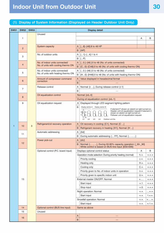
30
(1) Display of System Information (Displayed on Header Outdoor Unit Only)
Display detail
Unused
A B
System capacity A [...8]~[48]:8 to 48 HP
B [HP]
No. of outdoor units A [...1]~[...4]:1 to 4
B [...P]
No. of indoor units connected/ A [...0.]~[48.]:0 to 48 (No. of units connected)No. of units with cooling thermo ON B [C...0]~[C48]:0 to 48 (No. of units with cooling thermo ON)
No. of indoor units connected/ A [...0.]~[48.]:0 to 48 (No. of units connected)No. of units with heating thermo ON B [H...0]~[H48]:0 to 48 (No. of units with heating thermo ON)
Amount of compressor command A Value displayed in hexadecimal formatcorrection
B —
Release control A Normal: [r. ...], During release control: [r.1]
B —
Oil equalization control Normal: [oiL-0]
During oil equalization control: [oiL-1]
Oil equalization request A Displayed through LED segment lighting pattern
B
Refrigerant/oil recovery operation A Oil recovery in cooling: [C1], Normal: [C ...]
B Refrigerant recovery in heating: [H1], Normal: [H ...]
Automatic addressing A [Ad]
B During automatic addressing: [... FF], Normal: [... ... ...]
Power pick-cut A [dU]
B Normal: [... ... ...], During 50-90% capacity operation: [_50-_90]While control is based on BUS line input: [E50-E90]
Optional control (P.C. board input) Displays optional control status A B
Operation mode selection: During priority heating (normal) h.∗. ∗.∗.∗Priority cooling c.∗. ∗.∗.∗Heating only H.∗. ∗.∗.∗Cooling only C.∗. ∗.∗.∗Priority given to No. of indoor units in operation n.∗. ∗.∗.∗Priority given to specific indoor unit U.∗. ∗.∗.∗
External master ON/OFF: Normal ∗..... ∗.∗.∗Start input ∗.1. ∗.∗.∗Stop input ∗.0. ∗.∗.∗
Night operation: Normal ∗.∗. ....∗.∗.
Start input ∗.∗. 1.∗.∗.
Snowfall operation: Normal ∗.∗. ∗.....∗.
Start input ∗.∗. ∗.1.∗.
Optional control (BUS line input) Same as above
Unused
A —
B —
SW01 SW02 SW03
1
2
3
4
5
6
7
8
9
1 10 3
11
12
13
14
15
16
If element F shown on sketch at right turned on:Header unit oil equalization request If element Cshown on sketch at right turned on:Follower unit oil equalization request
F G
A
DU2U1 U3 U4
Dp
B
E C
Display section A Display section B
Outdoor unit No.
Indoor Unit from Outdoor Unit
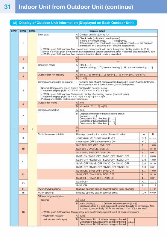
Display detail
Error data A Outdoor unit No.: [U1] to [U4]
B Check code (only latest one displayed)If there is no check code, [– – –] is displayed.If there is sub-code, check code [∗ ∗ ∗] and sub-code [- ∗ ∗] are displayedalternately, for 3 seconds and 1 second, respectively.
<SW04> push SW function: Fan operation at outdoor unit with error. 7-segment display section A: [E.1]<SW04 + SW05> push SW function: Fan operation at outdoor unit without error. 7-segment display section A: [E.0]<SW05> push SW function: Fan operation function check mode is cancelled.
— A —
B —
Operation mode A Stop [... ...]Normal cooling: [... C], Normal heating: [... H], Normal defrosting: [... J]
B —
Outdoor unit HP capacity A 8HP: [... 8], 10HP: [... 10], 12HP: [... 12], 14HP: [14], 16HP: [16]
B [... HP]
Compressor operation command ∗ Operation data of each compressor is displayed in turn in 2 second intervals.If compressor No. 3 does not exist, [--.---] is displayed.
Normal: Compressor speed (rps) is displayed in decimal format.7-segment display (A/B): [C1.∗ ∗ ∗] [C2.∗ ∗ ∗] [C3. ∗ ∗ ∗] ...
<SW04> push SW function: Switches to display of operating current (decimal value).7-segment display (A/B): [i1 ∗ ∗ ∗] [i2 ∗ ∗ ∗] [i3 ∗ ∗ ∗] Þ ...Pushing of <SW05> restores normal display.
Outdoor fan mode A [FP]
B Mode 0 to 63: [... 0] to [63]
Compressor backup A [C.b.]
B Displays compressor backup setting statusNormal: [... ... ...]Compressor No. 1 backup: [1 ... ...]Compressor No. 2 backup: [... 1 ...]Compressor No. 3 backup: [... ... 1]
— A —
B —
Control valve output data Displays control output status of solenoid valve A B
4-way valve: ON / 4-way valve 2: OFF H. 1 ... ... ...
4-way valve: OFF / 4-way valve 2: ON H. 0 ... ... ...
SV2: ON / SV5: OFF / SV6: OFF 2. ... 1 0 0
SV2: OFF / SV5: ON / SV6: ON 2. ... 0 1 0
SV2: OFF / SV5: OFF / SV6: ON 2. ... 0 0 1
SV3A: ON / SV3B: OFF / SV3C: OFF / SV3D: OFF 3. 1 0 0 0
SV3A: OFF / SV3B: ON / SV3C: OFF / SV3D: OFF 3. 0 1 0 0
SV3A: OFF / SV3B: OFF / SV3C: ON / SV3D: OFF 3. 0 0 1 0
SV3A: OFF / SV3B: OFF / SV3C: OFF / SV3D: ON 3. 0 0 0 1
SV41: ON / SV42: OFF / SV43: OFF 4. ... 1 0 0
SV41: OFF / SV42: ON / SV43: OFF 4. ... 0 1 0
SV41: OFF / SV42: OFF / SV43: ON 4. ... 0 0 1
SV3F: OFF A. ... ... ... 0
SV3F: ON A. ... ... ... 1
PMV1/PMV2 opening Displays opening data in decimal format (total opening) ∗ ∗ ∗ ∗.P
PMV4 opening Displays opening data in decimal format ... ∗ ∗ ∗.P
Oil level judgment status
Normal A [o L.]
B Initial display: [... ... ...], Oil level judgment result: [#.∗.$]Displayed letters #, ∗ and $ represent judgment results for compressor Nos.1, 2 and 3, respectively (“0” for normal and “1” or “2” for low level).
<SW04> push SW function: Displays low level confirmed judgment result of each compressor.
∗ Pushing of <SW05> A [L d.]
restores normal display. B Compressor No. 1 low level being confirmed: [L ... ...]Compressor No. 2 low level being confirmed: [... L ...]Compressor No. 3 low level being confirmed: [... ... L]
(2) Display of Outdoor Unit Information (Displayed on Each Outdoor Unit)
Indoor Unit from Outdoor Unit (continue)31
SW01 SW02 SW03
1
2
3
4
5
6
7
81 1
9
10
11
12
13
14
15
16
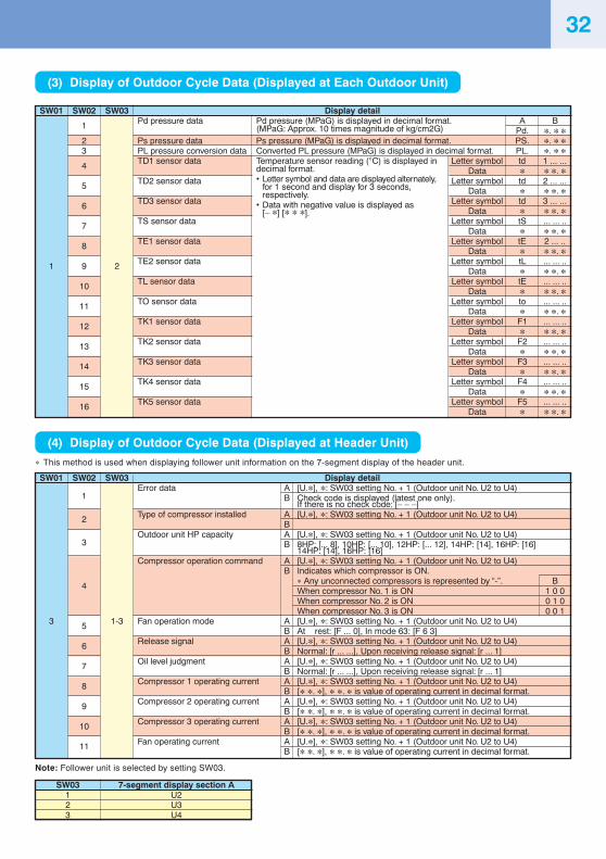
Display detailError data A [U.∗], ∗: SW03 setting No. + 1 (Outdoor unit No. U2 to U4)
B Check code is displayed (latest one only).If there is no check code: [– – –]
Type of compressor installed A [U.∗], ∗: SW03 setting No. + 1 (Outdoor unit No. U2 to U4)B
Outdoor unit HP capacity A [U.∗], ∗: SW03 setting No. + 1 (Outdoor unit No. U2 to U4)B 8HP: [... 8], 10HP: [... 10], 12HP: [... 12], 14HP: [14], 16HP: [16]
14HP: [14], 16HP: [16]Compressor operation command A [U.∗], ∗: SW03 setting No. + 1 (Outdoor unit No. U2 to U4)
B Indicates which compressor is ON.∗ Any unconnected compressors is represented by “-”. BWhen compressor No. 1 is ON 1 0 0When compressor No. 2 is ON 0 1 0When compressor No. 3 is ON 0 0 1
Fan operation mode A [U.∗], ∗: SW03 setting No. + 1 (Outdoor unit No. U2 to U4)B At rest: [F ... 0], In mode 63: [F 6 3]
Release signal A [U.∗], ∗: SW03 setting No. + 1 (Outdoor unit No. U2 to U4)B Normal: [r ... ...], Upon receiving release signal: [r ... 1]
Oil level judgment A [U.∗], ∗: SW03 setting No. + 1 (Outdoor unit No. U2 to U4)B Normal: [r ... ...], Upon receiving release signal: [r ... 1]
Compressor 1 operating current A [U.∗], ∗: SW03 setting No. + 1 (Outdoor unit No. U2 to U4)B [∗ ∗. ∗], ∗ ∗. ∗ is value of operating current in decimal format.
Compressor 2 operating current A [U.∗], ∗: SW03 setting No. + 1 (Outdoor unit No. U2 to U4)B [∗ ∗. ∗], ∗ ∗. ∗ is value of operating current in decimal format.
Compressor 3 operating current A [U.∗], ∗: SW03 setting No. + 1 (Outdoor unit No. U2 to U4)B [∗ ∗. ∗], ∗ ∗. ∗ is value of operating current in decimal format.
Fan operating current A [U.∗], ∗: SW03 setting No. + 1 (Outdoor unit No. U2 to U4)B [∗ ∗. ∗], ∗ ∗. ∗ is value of operating current in decimal format.
(3) Display of Outdoor Cycle Data (Displayed at Each Outdoor Unit)
SW01 SW02 SW03
1
23
4
5
6
7
8
1 9 2
10
11
12
13
14
15
16
(4) Display of Outdoor Cycle Data (Displayed at Header Unit)
∗ This method is used when displaying follower unit information on the 7-segment display of the header unit.
SW01 SW02 SW03
1
2
3
4
3 5 1-3
6
7
8
9
10
11
Note: Follower unit is selected by setting SW03.
SW03123
7-segment display section AU2U3U4
Display detailPd pressure data Pd pressure (MPaG) is displayed in decimal format. A B
(MPaG: Approx. 10 times magnitude of kg/cm2G) Pd. ∗. ∗ ∗Ps pressure data Ps pressure (MPaG) is displayed in decimal format. PS. ∗. ∗ ∗PL pressure conversion data Converted PL pressure (MPaG) is displayed in decimal format. PL. ∗. ∗ ∗TD1 sensor data Temperature sensor reading (°C) is displayed in Letter symbol td 1 ... ...
decimal format. Data ∗ ∗ ∗. ∗TD2 sensor data • Letter symbol and data are displayed alternately, Letter symbol td 2 ... ...
for 1 second and display for 3 seconds, Data ∗ ∗ ∗. ∗TD3 sensor data
respectively.Letter symbol td 3 ... ...• Data with negative value is displayed as
Data ∗ ∗ ∗. ∗TS sensor data
[– ∗] [∗ ∗ ∗].Letter symbol tS ... ... ..
Data ∗ ∗ ∗. ∗TE1 sensor data Letter symbol tE 2 ... ..
Data ∗ ∗ ∗. ∗TE2 sensor data Letter symbol tL ... ... ..
Data ∗ ∗ ∗. ∗TL sensor data Letter symbol tE ... ... ..
Data ∗ ∗ ∗. ∗TO sensor data Letter symbol to ... ... ..
Data ∗ ∗ ∗. ∗TK1 sensor data Letter symbol F1 ... ... ..
Data ∗ ∗ ∗. ∗TK2 sensor data Letter symbol F2 ... ... ..
Data ∗ ∗ ∗. ∗TK3 sensor data Letter symbol F3 ... ... ..
Data ∗ ∗ ∗. ∗TK4 sensor data Letter symbol F4 ... ... ..
Data ∗ ∗ ∗. ∗TK5 sensor data Letter symbol F5 ... ... ..
Data ∗ ∗ ∗. ∗
32
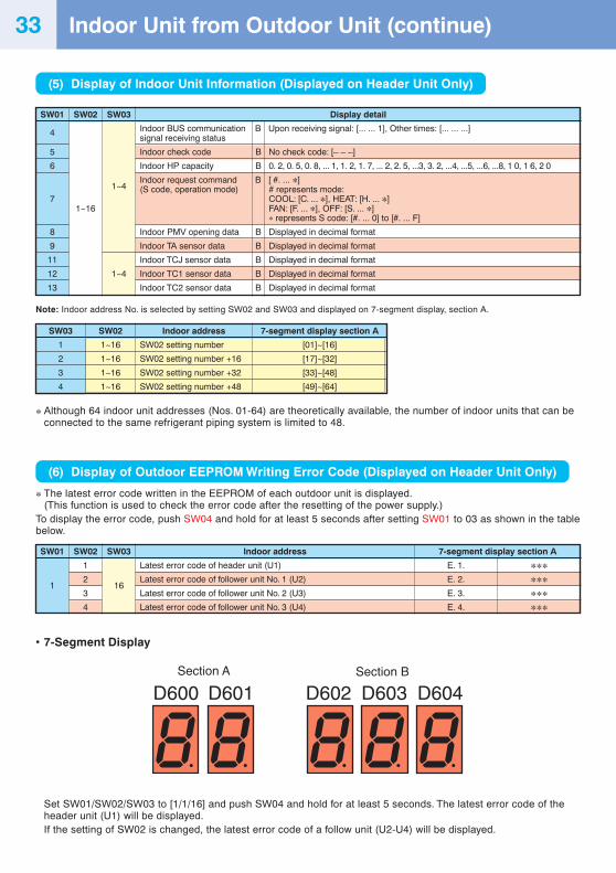
(5) Display of Indoor Unit Information (Displayed on Header Unit Only)
Display detail
Indoor BUS communication B Upon receiving signal: [... ... 1], Other times: [... ... ...]signal receiving status
Indoor check code B No check code: [– – –]
Indoor HP capacity B 0. 2, 0. 5, 0. 8, ... 1, 1. 2, 1. 7, ... 2, 2. 5, ...3, 3. 2, ...4, ...5, ...6, ...8, 1 0, 1 6, 2 0
Indoor request command B [ #. ... ∗](S code, operation mode) # represents mode:
COOL: [C. ... ∗], HEAT: [H. ... ∗]FAN: [F. ... ∗], OFF: [S. ... ∗]∗ represents S code: [#. ... 0] to [#. ... F]
Indoor PMV opening data B Displayed in decimal format
Indoor TA sensor data B Displayed in decimal format
Indoor TCJ sensor data B Displayed in decimal format
Indoor TC1 sensor data B Displayed in decimal format
Indoor TC2 sensor data B Displayed in decimal format
Note: Indoor address No. is selected by setting SW02 and SW03 and displayed on 7-segment display, section A.
Indoor address
SW02 setting number
SW02 setting number +16
SW02 setting number +32
SW02 setting number +48
7-segment display section A
[01]~[16]
[17]~[32]
[33]~[48]
[49]~[64]
∗ Although 64 indoor unit addresses (Nos. 01-64) are theoretically available, the number of indoor units that can beconnected to the same refrigerant piping system is limited to 48.
(6) Display of Outdoor EEPROM Writing Error Code (Displayed on Header Unit Only)
∗ The latest error code written in the EEPROM of each outdoor unit is displayed.(This function is used to check the error code after the resetting of the power supply.)
To display the error code, push SW04 and hold for at least 5 seconds after setting SW01 to 03 as shown in the tablebelow.
Indoor address
Latest error code of header unit (U1)
Latest error code of follower unit No. 1 (U2)
Latest error code of follower unit No. 2 (U3)
Latest error code of follower unit No. 3 (U4)
7-segment display section A
E. 1. ∗∗∗E. 2. ∗∗∗E. 3. ∗∗∗E. 4. ∗∗∗
• 7-Segment Display
Set SW01/SW02/SW03 to [1/1/16] and push SW04 and hold for at least 5 seconds. The latest error code of theheader unit (U1) will be displayed.If the setting of SW02 is changed, the latest error code of a follow unit (U2-U4) will be displayed.
Section A Section B
D600 D601 D602 D603 D604
Indoor Unit from Outdoor Unit (continue)
SW01 SW02 SW03
4
5
6
1~4
71~16
8
9
11
12 1~4
13
33
SW03
1
2
3
4
SW02
1~16
1~16
1~16
1~16
SW01 SW02 SW03
1
12
163
4
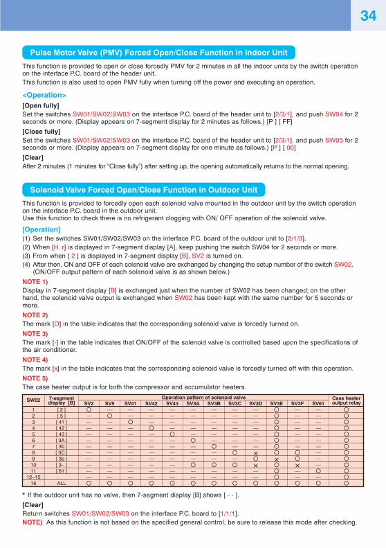
SW02
123456789
1011
12~1516
7-segmentdisplay [B]
[ 2 ][ 5 ][ 41 ][ 42 ][ 43 ][ 3A ][ 3b ][ 3C ][ 3b ][ 3– ][ 61 ]
ALL
Operation pattern of solenoid valveSV2 SV5 SV41 SV42 SV43 SV3A SV3B SV3C SV3D SV3E SV3F SV61
— — — — — — — — — —— — — — — — — — — —— — — — — — — — — —— — — — — — — — — —— — — — — — — — — —— — — — — — — — — —— — — — — — — — — —— — — — — — — × —— — — — — — — — × —— — — — — × × —— — — — — — — — — —— — — — — — — — — — —
Case heateroutput relay
34
Pulse Motor Valve (PMV) Forced Open/Close Function in Indoor Unit
This function is provided to open or close forcedly PMV for 2 minutes in all the indoor units by the switch operationon the interface P.C. board of the header unit.This function is also used to open PMV fully when turning off the power and executing an operation.
<Operation>[Open fully]Set the switches SW01/SW02/SW03 on the interface P.C. board of the header unit to [2/3/1], and push SW04 for 2seconds or more. (Display appears on 7-segment display for 2 minutes as follows.) [P ] [ FF]
[Close fully]Set the switches SW01/SW02/SW03 on the interface P.C. board of the header unit to [2/3/1], and push SW05 for 2seconds or more. (Display appears on 7-segment display for one minute as follows.) [P ] [ 00]
[Clear]After 2 minutes (1 minutes for “Close fully”) after setting up, the opening automatically returns to the normal opening.
Solenoid Valve Forced Open/Close Function in Outdoor Unit
This function is provided to forcedly open each solenoid valve mounted in the outdoor unit by the switch operationon the interface P.C. board in the outdoor unit.Use this function to check there is no refrigerant clogging with ON/ OFF operation of the solenoid valve.
[Operation](1) Set the switches SW01/SW02/SW03 on the interface P.C. board of the outdoor unit to [2/1/3].(2) When [H. r] is displayed in 7-segment display [A], keep pushing the switch SW04 for 2 seconds or more.(3) From when [ 2 ] is displayed in 7-segment display [B], SV2 is turned on.(4) After then, ON and OFF of each solenoid valve are exchanged by changing the setup number of the switch SW02.
(ON/OFF output pattern of each solenoid valve is as shown below.)
NOTE 1)Display in 7-segment display [B] is exchanged just when the number of SW02 has been changed; on the otherhand, the solenoid valve output is exchanged when SW02 has been kept with the same number for 5 seconds ormore.
NOTE 2)The mark [O] in the table indicates that the corresponding solenoid valve is forcedly turned on.
NOTE 3)The mark [-] in the table indicates that ON/OFF of the solenoid valve is controlled based upon the specifications ofthe air conditioner.
NOTE 4)The mark [x] in the table indicates that the corresponding solenoid valve is forcedly turned off with this operation.
NOTE 5)The case heater output is for both the compressor and accumulator heaters.
* If the outdoor unit has no valve, then 7-segment display [B] shows [ - - ].
[Clear]Return switches SW01/SW02/SW03 on the interface P.C. board to [1/1/1].NOTE) As this function is not based on the specified general control, be sure to release this mode after checking.
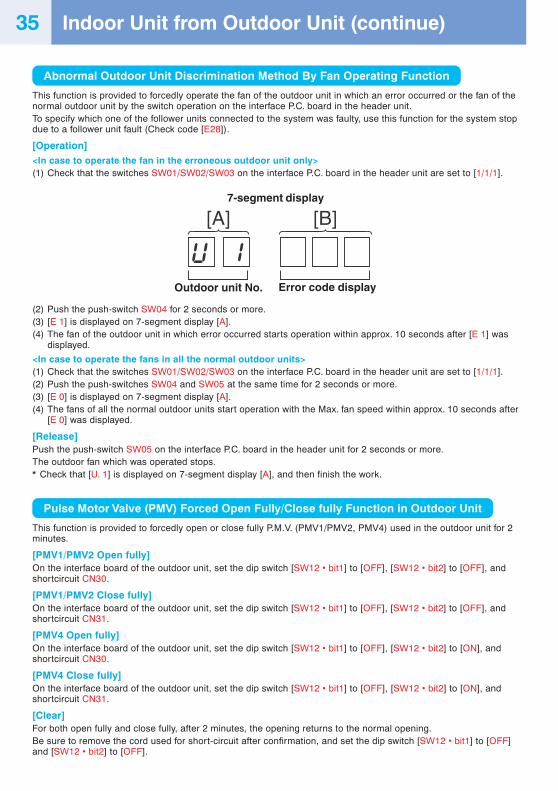
Abnormal Outdoor Unit Discrimination Method By Fan Operating Function
This function is provided to forcedly operate the fan of the outdoor unit in which an error occurred or the fan of thenormal outdoor unit by the switch operation on the interface P.C. board in the header unit.To specify which one of the follower units connected to the system was faulty, use this function for the system stopdue to a follower unit fault (Check code [E28]).
[Operation]<In case to operate the fan in the erroneous outdoor unit only>(1) Check that the switches SW01/SW02/SW03 on the interface P.C. board in the header unit are set to [1/1/1].
(2) Push the push-switch SW04 for 2 seconds or more.(3) [E 1] is displayed on 7-segment display [A].(4) The fan of the outdoor unit in which error occurred starts operation within approx. 10 seconds after [E 1] was
displayed.
<In case to operate the fans in all the normal outdoor units>(1) Check that the switches SW01/SW02/SW03 on the interface P.C. board in the header unit are set to [1/1/1].(2) Push the push-switches SW04 and SW05 at the same time for 2 seconds or more.(3) [E 0] is displayed on 7-segment display [A].(4) The fans of all the normal outdoor units start operation with the Max. fan speed within approx. 10 seconds after
[E 0] was displayed.
[Release]Push the push-switch SW05 on the interface P.C. board in the header unit for 2 seconds or more.The outdoor fan which was operated stops.* Check that [U. 1] is displayed on 7-segment display [A], and then finish the work.
Pulse Motor Valve (PMV) Forced Open Fully/Close fully Function in Outdoor Unit
This function is provided to forcedly open or close fully P.M.V. (PMV1/PMV2, PMV4) used in the outdoor unit for 2minutes.
[PMV1/PMV2 Open fully]On the interface board of the outdoor unit, set the dip switch [SW12 • bit1] to [OFF], [SW12 • bit2] to [OFF], andshortcircuit CN30.
[PMV1/PMV2 Close fully]On the interface board of the outdoor unit, set the dip switch [SW12 • bit1] to [OFF], [SW12 • bit2] to [OFF], andshortcircuit CN31.
[PMV4 Open fully]On the interface board of the outdoor unit, set the dip switch [SW12 • bit1] to [OFF], [SW12 • bit2] to [ON], andshortcircuit CN30.
[PMV4 Close fully]On the interface board of the outdoor unit, set the dip switch [SW12 • bit1] to [OFF], [SW12 • bit2] to [ON], andshortcircuit CN31.
[Clear]For both open fully and close fully, after 2 minutes, the opening returns to the normal opening.Be sure to remove the cord used for short-circuit after confirmation, and set the dip switch [SW12 • bit1] to [OFF]and [SW12 • bit2] to [OFF].
[A] [B]7-segment display
Outdoor unit No. Error code display
Indoor Unit from Outdoor Unit (continue)35
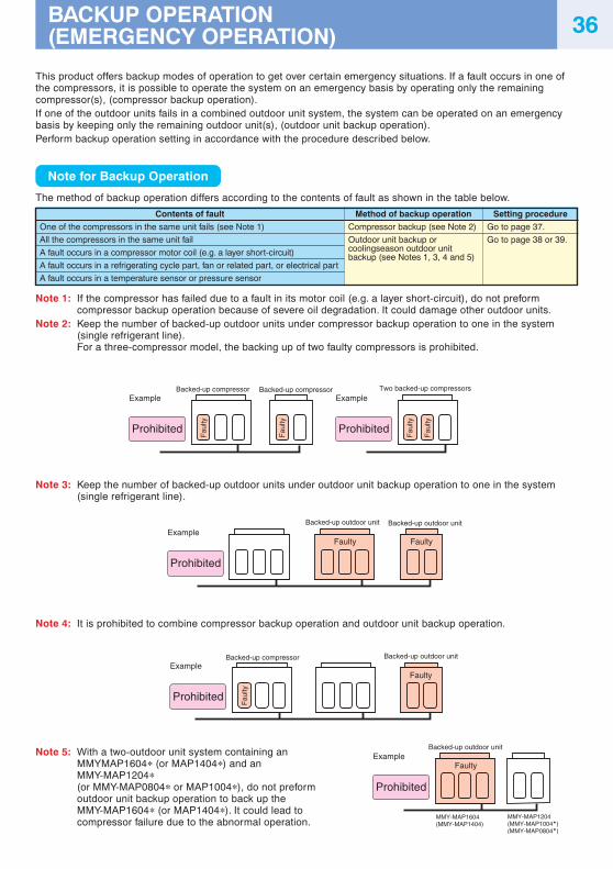
Fau
lty
Fau
lty
Example
Prohibited
Example
Prohibited
Backed-up compressor Backed-up compressor Two backed-up compressors
Fau
lty
Fau
lty
Example
Prohibited
Faulty
Backed-up outdoor unit Backed-up outdoor unit
Faulty
Fau
lty
Example
Prohibited
Backed-up compressor Backed-up outdoor unit
Faulty
MMY-MAP1604(MMY-MAP1404)
MMY-MAP1204(MMY-MAP1004�)(MMY-MAP0804�)
Example
Prohibited
Faulty
Backed-up outdoor unit
36BACKUP OPERATION(EMERGENCY OPERATION)
This product offers backup modes of operation to get over certain emergency situations. If a fault occurs in one ofthe compressors, it is possible to operate the system on an emergency basis by operating only the remainingcompressor(s), (compressor backup operation).If one of the outdoor units fails in a combined outdoor unit system, the system can be operated on an emergencybasis by keeping only the remaining outdoor unit(s), (outdoor unit backup operation).Perform backup operation setting in accordance with the procedure described below.
Note for Backup Operation
The method of backup operation differs according to the contents of fault as shown in the table below.
Contents of faultOne of the compressors in the same unit fails (see Note 1)
All the compressors in the same unit fail
A fault occurs in a compressor motor coil (e.g. a layer short-circuit)
A fault occurs in a refrigerating cycle part, fan or related part, or electrical part
A fault occurs in a temperature sensor or pressure sensor
Method of backup operationCompressor backup (see Note 2)
Outdoor unit backup orcoolingseason outdoor unitbackup (see Notes 1, 3, 4 and 5)
Setting procedureGo to page 37.
Go to page 38 or 39.
Note 1: If the compressor has failed due to a fault in its motor coil (e.g. a layer short-circuit), do not preformcompressor backup operation because of severe oil degradation. It could damage other outdoor units.
Note 2: Keep the number of backed-up outdoor units under compressor backup operation to one in the system(single refrigerant line).For a three-compressor model, the backing up of two faulty compressors is prohibited.
Note 3: Keep the number of backed-up outdoor units under outdoor unit backup operation to one in the system(single refrigerant line).
Note 4: It is prohibited to combine compressor backup operation and outdoor unit backup operation.
Note 5: With a two-outdoor unit system containing anMMYMAP1604∗ (or MAP1404∗) and anMMY-MAP1204∗(or MMY-MAP0804∗ or MAP1004∗), do not preformoutdoor unit backup operation to back up theMMY-MAP1604∗ (or MAP1404∗). It could lead tocompressor failure due to the abnormal operation.
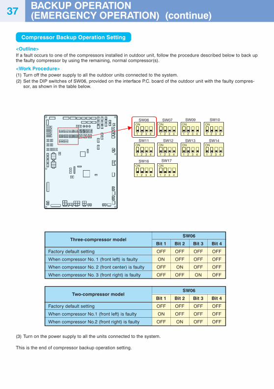
Compressor Backup Operation Setting
<Outline>If a fault occurs to one of the compressors installed in outdoor unit, follow the procedure described below to back upthe faulty compressor by using the remaining, normal compressor(s).
<Work Procedure>(1) Turn off the power supply to all the outdoor units connected to the system.(2) Set the DIP switches of SW06, provided on the interface P.C. board of the outdoor unit with the faulty compres-
sor, as shown in the table below.
SW06
Bit 1 Bit 2 Bit 3 Bit 4
OFF OFF OFF OFF
ON OFF OFF OFF
OFF ON OFF OFF
OFF OFF ON OFF
Three-compressor model
Factory default setting
When compressor No. 1 (front left) is faulty
When compressor No. 2 (front center) is faulty
When compressor No. 3 (front right) is faulty
Two-compressor model
Factory default setting
When compressor No.1 (front left) is faulty
When compressor No.2 (front right) is faulty
SW06
Bit 1 Bit 2 Bit 3 Bit 4
OFF OFF OFF OFF
ON OFF OFF OFF
OFF ON OFF OFF
(3) Turn on the power supply to all the units connected to the system.
This is the end of compressor backup operation setting.
1 2 3 4 1 2 3 4 1 2 3 4 1 2 3 4
1 2 3 4 1 2 3 4 1 2 3 4 1 2 3 4
SW06 SW07 SW09 SW10
SW11 SW12
1 2 3 4 1 2 3 4
SW16 SW17
SW13 SW14
BACKUP OPERATION(EMERGENCY OPERATION) (continue)37
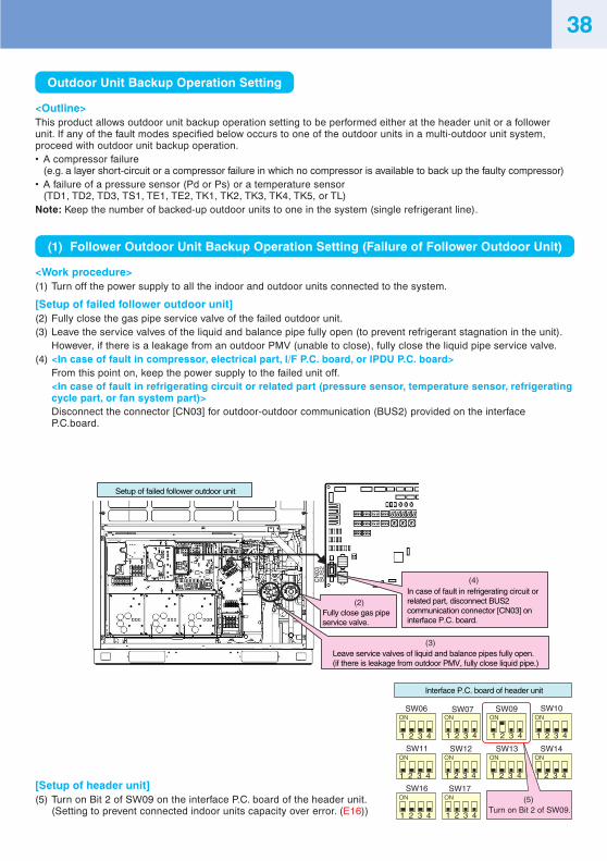
Outdoor Unit Backup Operation Setting
<Outline>This product allows outdoor unit backup operation setting to be performed either at the header unit or a followerunit. If any of the fault modes specified below occurs to one of the outdoor units in a multi-outdoor unit system,proceed with outdoor unit backup operation.• A compressor failure
(e.g. a layer short-circuit or a compressor failure in which no compressor is available to back up the faulty compressor)• A failure of a pressure sensor (Pd or Ps) or a temperature sensor
(TD1, TD2, TD3, TS1, TE1, TE2, TK1, TK2, TK3, TK4, TK5, or TL)Note: Keep the number of backed-up outdoor units to one in the system (single refrigerant line).
(1) Follower Outdoor Unit Backup Operation Setting (Failure of Follower Outdoor Unit)
<Work procedure>(1) Turn off the power supply to all the indoor and outdoor units connected to the system.
[Setup of failed follower outdoor unit](2) Fully close the gas pipe service valve of the failed outdoor unit.(3) Leave the service valves of the liquid and balance pipe fully open (to prevent refrigerant stagnation in the unit).
However, if there is a leakage from an outdoor PMV (unable to close), fully close the liquid pipe service valve.(4) <In case of fault in compressor, electrical part, I/F P.C. board, or IPDU P.C. board>
From this point on, keep the power supply to the failed unit off.<In case of fault in refrigerating circuit or related part (pressure sensor, temperature sensor, refrigeratingcycle part, or fan system part)>Disconnect the connector [CN03] for outdoor-outdoor communication (BUS2) provided on the interfaceP.C.board.
[Setup of header unit](5) Turn on Bit 2 of SW09 on the interface P.C. board of the header unit.
(Setting to prevent connected indoor units capacity over error. (E16))
Setup of failed follower outdoor unit
(2)
(3)
(4)CN
03B
US
2
Fully close gas pipe service valve.
In case of fault in refrigerating circuit or related part, disconnect BUS2 communication connector [CN03] on interface P.C. board.
1 2 3 4 1 2 3 4 1 2 3 4 1 2 3 4
1 2 3 4 1 2 3 4
1 2 3 4 1 2 3 4
1 2 3 4 1 2 3 4
SW06 SW07 SW09 SW10
SW11 SW12
SW16 SW17
SW13 SW14
Interface P.C. board of header unit
(5)Turn on Bit 2 of SW09.
Leave service valves of liquid and balance pipes fully open. (if there is leakage from outdoor PMV, fully close liquid pipe.)
38
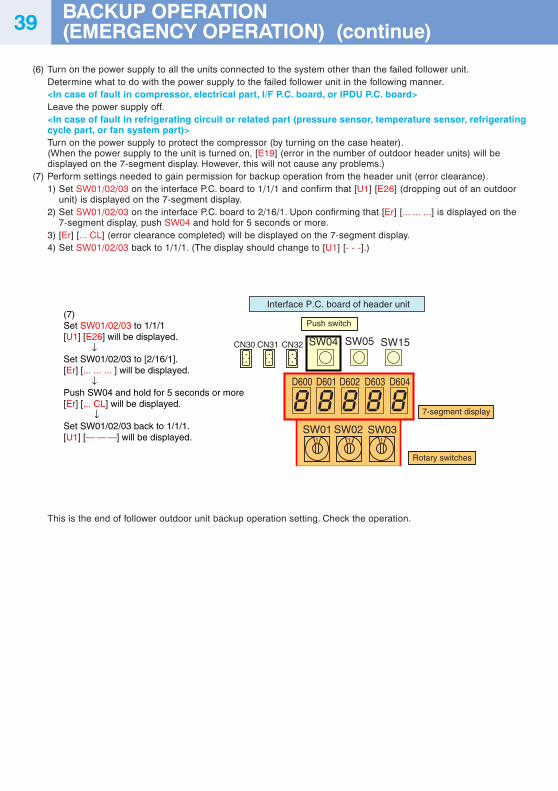
(6) Turn on the power supply to all the units connected to the system other than the failed follower unit.Determine what to do with the power supply to the failed follower unit in the following manner.<In case of fault in compressor, electrical part, I/F P.C. board, or IPDU P.C. board>Leave the power supply off.<In case of fault in refrigerating circuit or related part (pressure sensor, temperature sensor, refrigeratingcycle part, or fan system part)>Turn on the power supply to protect the compressor (by turning on the case heater).(When the power supply to the unit is turned on, [E19] (error in the number of outdoor header units) will bedisplayed on the 7-segment display. However, this will not cause any problems.)
(7) Perform settings needed to gain permission for backup operation from the header unit (error clearance).1) Set SW01/02/03 on the interface P.C. board to 1/1/1 and confirm that [U1] [E26] (dropping out of an outdoor
unit) is displayed on the 7-segment display.2) Set SW01/02/03 on the interface P.C. board to 2/16/1. Upon confirming that [Er] [... ... ...] is displayed on the
7-segment display, push SW04 and hold for 5 seconds or more.3) [Er] [... CL] (error clearance completed) will be displayed on the 7-segment display.4) Set SW01/02/03 back to 1/1/1. (The display should change to [U1] [- - -].)
This is the end of follower outdoor unit backup operation setting. Check the operation.
Push switch
7-segment display
Rotary switches
Interface P.C. board of header unit
SW04
SW01 SW02 SW03
D600 D601 D602 D603 D604
SW05CN30 CN31 CN32 SW15
(7)Set SW01/02/03 to 1/1/1[U1] [E26] will be displayed. ↓Set SW01/02/03 to [2/16/1].[Er] [... ... ... ] will be displayed. ↓Push SW04 and hold for 5 seconds or more[Er] [... CL] will be displayed. ↓Set SW01/02/03 back to 1/1/1.[U1] [— — —] will be displayed.
BACKUP OPERATION(EMERGENCY OPERATION) (continue)39
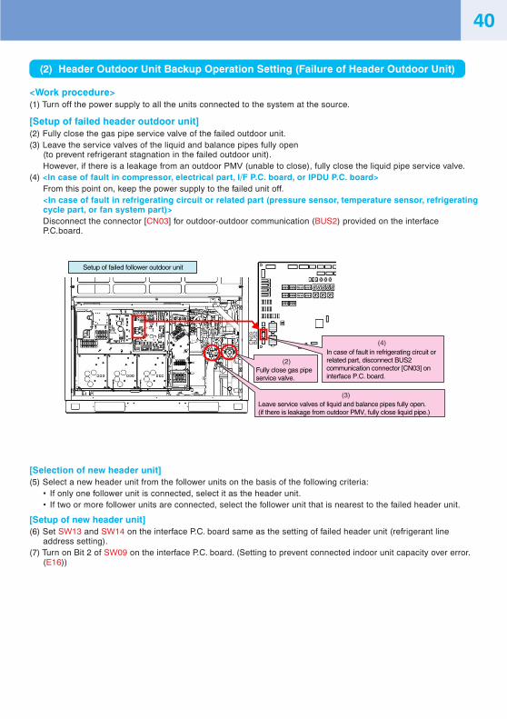
40
(2) Header Outdoor Unit Backup Operation Setting (Failure of Header Outdoor Unit)
<Work procedure>(1) Turn off the power supply to all the units connected to the system at the source.
[Setup of failed header outdoor unit](2) Fully close the gas pipe service valve of the failed outdoor unit.(3) Leave the service valves of the liquid and balance pipes fully open
(to prevent refrigerant stagnation in the failed outdoor unit).However, if there is a leakage from an outdoor PMV (unable to close), fully close the liquid pipe service valve.
(4) <In case of fault in compressor, electrical part, I/F P.C. board, or IPDU P.C. board>From this point on, keep the power supply to the failed unit off.<In case of fault in refrigerating circuit or related part (pressure sensor, temperature sensor, refrigeratingcycle part, or fan system part)>Disconnect the connector [CN03] for outdoor-outdoor communication (BUS2) provided on the interfaceP.C.board.
Setup of failed follower outdoor unit
(2)
(3)
(4)CN
03B
US
2
Fully close gas pipe service valve.
Leave service valves of liquid and balance pipes fully open. (if there is leakage from outdoor PMV, fully close liquid pipe.)
In case of fault in refrigerating circuit or related part, disconnect BUS2 communication connector [CN03] on interface P.C. board.
[Selection of new header unit](5) Select a new header unit from the follower units on the basis of the following criteria:
• If only one follower unit is connected, select it as the header unit.• If two or more follower units are connected, select the follower unit that is nearest to the failed header unit.
[Setup of new header unit](6) Set SW13 and SW14 on the interface P.C. board same as the setting of failed header unit (refrigerant line
address setting).(7) Turn on Bit 2 of SW09 on the interface P.C. board. (Setting to prevent connected indoor unit capacity over error.
(E16))
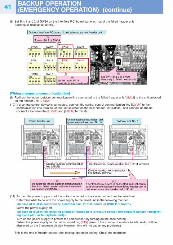
41
(8) Set Bits 1 and 2 of SW30 on the interface P.C. board same as that of the failed header unit(terminator resistance setting).
1 2 3 4 1 2 3 4 1 2 3 4 1 2 3 4
1 2 3 4 1 2 3 4 1 2 3 4 1 2 3 4
SW06 SW07 SW09 SW10
SW11 SW12
1 2 3 4 1 2 3 4
SW16 SW17
SW13 SW14
(6)
(8)
Outdoor interface P.C. board of unit selected as new header unit
(7)Turn on Bit 2 of SW09.
Set SW13 and SW14 identically to failed header unit.
Set SW 1 and 2 of SW30identically to failed header unit.
[Wiring changes to communication line](9) Redirect the indoor-outdoor communication line connected to the failed header unit [U1/U2] to the unit selected
as the header unit [U1/U2].(10) If a central control device is connected, connect the central control communication line [U3/U4] to the
communication line terminal of the unit selected as the new header unit [U3/U4], and connect up the tieconnector between the [U1/U2] and [U3/U4] terminals.
(10)
Failed header unit
Outdoor-outdoor communication line (U5/U6)
(9)Redirect the indoor-outdoor communication line from failed header unit to unit selected as header unit [U1/U2].
If central control device is connected, redirect central control communication line from failed header unit to unit selected as new header unit [U3/U4].
Unit selected as new header unit (previously follower unit No. 1)
Central control communication line (U3/U4 terminal)
Outdoor-outdoor communication line (U1/U2 terminal)
Follower unit No. 2
(11) Turn on the power supply to all the units connected to the system other than the failed unit.Determine what to do with the power supply to the failed unit in the following manner.<In case of fault in compressor, electrical part, I/F P.C. board, or IPDU P.C. board>Leave the power supply off.<In case of fault in refrigerating circuit or related part (pressure sensor, temperature sensor, refrigerat-ing cycle part, or fan system part)>Turn on the power supply to protect the compressor (by turning on the case heater).(When the power supply to the unit is turned on, [E19] (error in the number of outdoor header units) will bedisplayed on the 7-segment display. However, this will not cause any problems.)
This is the end of header outdoor unit backup operation setting. Check the operation.
BACKUP OPERATION(EMERGENCY OPERATION) (continue)
42OUTDOOR UNIT REFRIGERANTRECOVERY METHOD
Refrigerant Recovery from Failed Outdoor Unit (Pump-Down)
This product supports refrigerant pump-down, a function which allows refrigerant to be recovered from an outdoorunit in need of repair using a normal outdoor unit in a system featuring multiple outdoor units.
(1) Note for Refrigerant Recovery Operation
When performing pump-down operation, take note of the following matters:Note 1: The pump-down refrigerant recovery rate changes with outside temperature and other factors.
After pump-down is completed, recover any residual gas using a refrigerant recovery device, etc., and besure to measure the amount of recovered refrigerant. (The refrigerant recovery rate can be improved byheating the accumulator of the outdoor unit to be repaired during pump-down operation.)
Note 2: If pump-down has been performed, the system cannot be operated until the faulty outdoor unit is repaired.(Continued operation would be impossible due to a refrigerant overcharge.)
Note 3: If outdoor PMVs 1 and 2 both happen to be faulty (unable to open) or PMV 4 fails while fully closed, therefrigerant in the heat exchangers (or sub-heat exchangers) cannot be recovered. In that case, recover anyresidual gas in the heat exchangers (or sub-heat exchangers) using a tube piercing valve or some othertool. After a pump-down operation, do not perform any welding until the residual gas in the heat exchang-ers is recovered.
(2) Refrigerant Recovery Procedure A (Case of No Outdoor Unit Backup Operation Setting)
<Work procedure>Turn on the power supply to the system at the source, but leave the system switched off.If the fault involves poor insulation of a compressor motor, remove the motor leads before the power is turned on.
[Setup of failed outdoor unit](1) Connect the check joint of liquid pipe and the low pressure-side check joint using a charge hose, and purge the
hose of air (to recover refrigerant from the liquid tank and heat exchangers).(2) Fully close the liquid pipe service valve of the failed outdoor unit.
(Leave the service valves of the gas and balance pipes fully open.)(3) If the oil is likely to has degraded due to a compressor fault, disconnect the SV3A valve connector of the failed
outdoor unit (to prevent the degraded oil from flowing into other outdoor units).(4) Set SW01/02/03 on the interface P.C. board of the failed outdoor unit to 2/11/1.
After [rd] [... ... ...] is displayed on the 7-segment display, push SW04 and hold for 5 seconds or more.
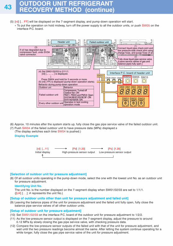
43
(5) [rd] [... FF] will be displayed on the 7-segment display, and pump-down operation will start.∗ To put the operation on hold midway, turn off the power supply to all the outdoor units, or push SW05 on the
interface P.C. board.
Interface P.C. board of header unit
SW04
SW01 SW02 SW03
D600 D601 D602 D603 D604
SW05CN30 CN31 CN32 SW15
Failed outdoor unitHeader unit
(1)
(2)
(3) Connect liquid pipe check joint and low pressure-side check joint using charge hose, and purge hose of air.
.
Fully close liquid pipe service valve. (Leave service valves of gas and balance pipes fully open.)
If oil has degraded due to compressor fault, undo SV3A valve connector.
(4) Set SW01/02/03 to 2/11/1. [rd] [... ... ... ] is displayed. ↓
Press SW04 and hold for 5 seconds or more.
(5) [rd] [ FF] is displayed (pump-down operation starts).
Behavior during pump-down operationOutdoor uni Behavior
Failed outdoor unit
Compressors: Turned off Outdoor fan: ON PMV1, PMV2 and PMV4: Open SV2/3A/3B/3C/3D/3E/3F: ON SV41/42/43/5/6: ON
Every other outdoor unit Operates in test cooling operation mode
(6) Approx. 10 minutes after the system starts up, fully close the gas pipe service valve of the failed outdoor unit.(7) Push SW04 of the failed outdoor unit to have pressure data (MPa) displayed.s
(The display switches each time SW04 is pushed.)
Display Example
[rd] [...11]Initial display
[Pd] [1.20]High-pressure sensor output
[Ps] [1.20]Low-pressure sensor output
[Selection of outdoor unit for pressure adjustment](8) Of all outdoor units operating in the pump-down mode, select the one with the lowest unit No. as an outdoor unit
for pressure adjustment.
Identifying Unit No.The unit No. is the number displayed on the 7-segment display when SW01/02/03 are set to 1/1/1.([U#] [. . .]: # represents the unit No.)
[Setup of outdoor units other than unit for pressure adjustment and failed unit](9) Leaving the balance pipes of the unit for pressure adjustment and the failed unit fully open, fully close the
balance pipe service valves of all other outdoor units.
[Setup of outdoor unit for pressure adjustment](10) Set SW01/02/03 on the interface P.C. board of the outdoor unit for pressure adjustment to 1/2/2.(11) As the low-pressure sensor output is displayed on the 7-segment display, adjust the pressure to around
0.12 MPa by slowly closing the gas pipe service valve, with checking pressure data.(12) Compare the low-pressure sensor outputs of the failed unit with that of the unit for pressure adjustment, and
wait until the two pressure readings become almost the same. After letting the system continue operating for awhile longer, fully close the gas pipe service valve of the unit for pressure adjustment.
OUTDOOR UNIT REFRIGERANTRECOVERY METHOD (continue)
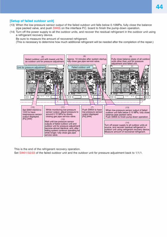
44
[Setup of failed outdoor unit](13) When the low-pressure sensor output of the failed outdoor unit falls below 0.10MPa, fully close the balance
pipe packed valve, and push SW05 on the interface P.C. board to finish the pump-down operation.(14) Turn off the power supply to all the outdoor units, and recover the residual refrigerant in the outdoor unit using
a refrigerant recovery device.Be sure to measure the amount of recovered refrigerant.(This is necessary to determine how much additional refrigerant will be needed after the completion of the repair.)
This is the end of the refrigerant recovery operation.Set SW01/02/03 of the failed outdoor unit and the outdoor unit for pressure adjustment back to 1/1/1.
Failed outdoor unitUnit for pressure adjustment
(9)(6)
(11)
(12)
(14)
(13)
Approx. 10 minutes after system startup, fully close gas pipe service valve.
(8)Select outdoor unit with lowest unit No. as outdoor unit for pressure adjustment.
Fully close balance pipes of all outdoor units other than unit for pressure adjustment and failed unit.
While monitoring low-pressure sensor output, adjust pressure to around 0.12 MPa by slowly closing gas pipe service valve.
When low-pressure sensor output of failed outdoor unit falls below 0.10 MPa, fully close balance pipe packed valve. Push SW05 to finish pump-down operation.
Turn off power supply to all outdoor units at source, and recover residual refrigerant in outdoor unit using refrigerant recovery device. Measure amount of recovered refrigerant.
Wait until low-pressure sensor outputs of failed outdoor unit and outdoor unit for pressure adjustment become almost identical, and, after letting system continue operating for while longer, fully close gas pipe service valve.
(7)Push SW04 to have low-pressure sensor output displayed [Ps] [###]
(10)Set SW01/02/03 to 1/2/2 to have lowpressure sensor output displayed. [Ps] [###]
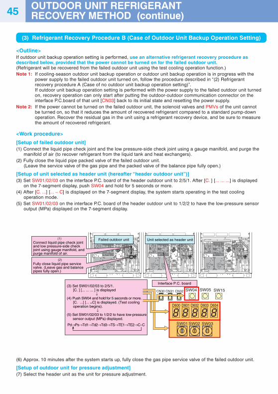
45
(3) Refrigerant Recovery Procedure B (Case of Outdoor Unit Backup Operation Setting)
<Outline>If outdoor unit backup operation setting is performed, use an alternative refrigerant recovery procedure asdescribed below, provided that the power cannot be turned on for the failed outdoor unit.(Refrigerant will be recovered from the failed outdoor unit using the test cooling operation function.)Note 1: If cooling-season outdoor unit backup operation or outdoor unit backup operation is in progress with the
power supply to the failed outdoor unit turned on, follow the procedure described in “(2) Refrigerantrecovery procedure A (Case of no outdoor unit backup operation setting)”.If outdoor unit backup operation setting is performed with the power supply to the failed outdoor unit turnedon, recovery operation can only start after putting the outdoor-outdoor communication connector on theinterface P.C.board of that unit [CN03] back to its initial state and resetting the power supply.
Note 2: If the power cannot be turned on the failed outdoor unit, the solenoid valves and PMVs of the unit cannotbe turned on, so that it reduces the amount of recovered refrigerant compared to a standard pump-downoperation. Recover the residual gas in the unit using a refrigerant recovery device, and be sure to measurethe amount of recovered refrigerant.
<Work procedure>
[Setup of failed outdoor unit](1) Connect the liquid pipe check joint and the low pressure-side check joint using a gauge manifold, and purge the
manifold of air (to recover refrigerant from the liquid tank and heat exchangers).(2) Fully close the liquid pipe packed valve of the failed outdoor unit.
(Leave the service valve of the gas pipe and the packed valve of the balance pipe fully open.)
[Setup of unit selected as header unit (hereafter “header outdoor unit”)](3) Set SW01/02/03 on the interface P.C. board of the header outdoor unit to 2/5/1. After [C. ] [... ... ...] is displayed
on the 7-segment display, push SW04 and hold for 5 seconds or more.(4) After [C. ...] [... – C] is displayed on the 7-segment display, the system starts operating in the test cooling
operation mode.(5) Set SW01/02/03 on the interface P.C. board of the header outdoor unit to 1/2/2 to have the low-pressure sensor
output (MPa) displayed on the 7-segment display.
(6) Approx. 10 minutes after the system starts up, fully close the gas pipe service valve of the failed outdoor unit.
[Setup of outdoor unit for pressure adjustment](7) Select the header unit as the unit for pressure adjustment.
SW04
SW01 SW02 SW03
D600 D601 D602 D603 D604
SW05CN30 CN31 CN32 SW15
(1)
(2)
Connect liquid pipe check joint and low pressure-side check joint using gauge manifold, and purge manifold of air.
Failed outdoor unit Unit selected as header unit
Interface P.C. board
Fully close liquid pipe service valve. (Leave gas and balance pipes fully open.)
Pd→Ps→Td1→Td2→Td3→TS→TE1→TE2→C~C
(3) Set SW01/02/03 to 2/5/1. [C. ] [... ... ... ] is displayed ↓(4) Push SW04 and hold for 5 seconds or more. [C. ...] [... –C] is displayed. (Test cooling operation begins). ↓(5) Set SW01/02/03 to 1/2/2 to have low-pressure sensor output (MPa) displayed.
OUTDOOR UNIT REFRIGERANTRECOVERY METHOD (continue)
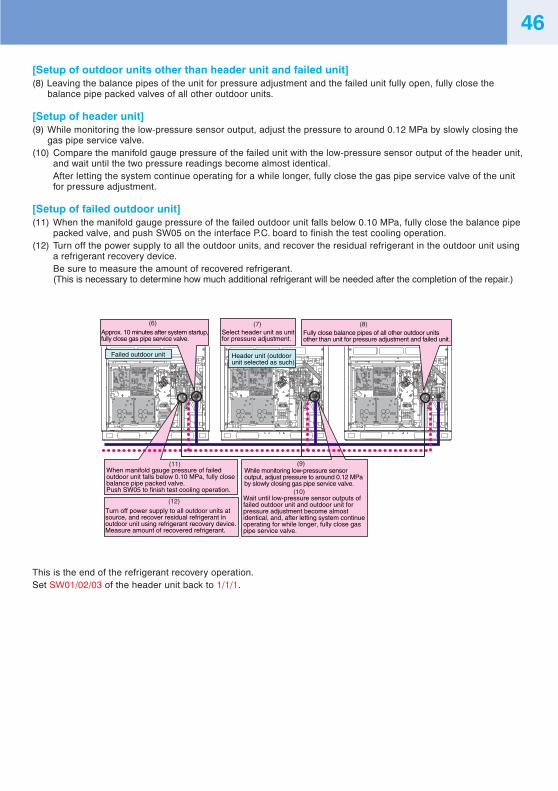
46
[Setup of outdoor units other than header unit and failed unit](8) Leaving the balance pipes of the unit for pressure adjustment and the failed unit fully open, fully close the
balance pipe packed valves of all other outdoor units.
[Setup of header unit](9) While monitoring the low-pressure sensor output, adjust the pressure to around 0.12 MPa by slowly closing the
gas pipe service valve.(10) Compare the manifold gauge pressure of the failed unit with the low-pressure sensor output of the header unit,
and wait until the two pressure readings become almost identical.After letting the system continue operating for a while longer, fully close the gas pipe service valve of the unitfor pressure adjustment.
[Setup of failed outdoor unit](11) When the manifold gauge pressure of the failed outdoor unit falls below 0.10 MPa, fully close the balance pipe
packed valve, and push SW05 on the interface P.C. board to finish the test cooling operation.(12) Turn off the power supply to all the outdoor units, and recover the residual refrigerant in the outdoor unit using
a refrigerant recovery device.Be sure to measure the amount of recovered refrigerant.(This is necessary to determine how much additional refrigerant will be needed after the completion of the repair.)
This is the end of the refrigerant recovery operation.Set SW01/02/03 of the header unit back to 1/1/1.
(8)(6) (7)
(9)
(10)
(12)
(11)
Approx. 10 minutes after system startup, fully close gas pipe service valve.
Select header unit as unit for pressure adjustment.
Fully close balance pipes of all other outdoor units other than unit for pressure adjustment and failed unit.
Header unit (outdoor unit selected as such)
Wait until low-pressure sensor outputs of failed outdoor unit and outdoor unit for pressure adjustment become almost identical, and, after letting system continue operating for while longer, fully close gas pipe service valve.
While monitoring low-pressure sensor output, adjust pressure to around 0.12 MPa by slowly closing gas pipe service valve.
Turn off power supply to all outdoor units at source, and recover residual refrigerant in outdoor unit using refrigerant recovery device. Measure amount of recovered refrigerant.
When manifold gauge pressure of failed outdoor unit falls below 0.10 MPa, fully close balance pipe packed valve. Push SW05 to finish test cooling operation.
Failed outdoor unit
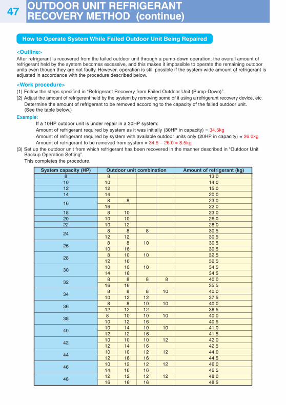
47
How to Operate System While Failed Outdoor Unit Being Repaired
<Outline>After refrigerant is recovered from the failed outdoor unit through a pump-down operation, the overall amount ofrefrigerant held by the system becomes excessive, and this makes it impossible to operate the remaining outdoorunits even though they are not faulty. However, operation is still possible if the system-wide amount of refrigerant isadjusted in accordance with the procedure described below.
<Work procedure>(1) Follow the steps specified in “Refrigerant Recovery from Failed Outdoor Unit (Pump-Down)”.(2) Adjust the amount of refrigerant held by the system by removing some of it using a refrigerant recovery device, etc.
Determine the amount of refrigerant to be removed according to the capacity of the failed outdoor unit.(See the table below.)
Example:If a 10HP outdoor unit is under repair in a 30HP system:Amount of refrigerant required by system as it was initially (30HP in capacity) = 34.5kgAmount of refrigerant required by system with available outdoor units only (20HP in capacity) = 26.0kgAmount of refrigerant to be removed from system = 34.5 – 26.0 = 8.5kg
(3) Set up the outdoor unit from which refrigerant has been recovered in the manner described in “Outdoor UnitBackup Operation Setting”.This completes the procedure.
System capacity (HP)8
101214
16
182022
24
26
28
30
32
34
36
38
40
42
44
46
48
Outdoor unit combination 8101214 8 816 8 1010 1010 12 8 8 812 12 8 8 1010 16 8 10 1012 1610 10 1014 16 8 8 8 816 16 8 8 8 1010 12 12 8 8 10 1012 12 128 10 10 10
10 12 1610 14 10 1012 12 1610 10 10 1212 14 1610 10 12 1212 16 1610 12 12 1214 16 1612 12 12 1216 16 16
Amount of refrigerant (kg)13.014.015.020.023.022.023.026.028.030.530.530.530.532.532.534.534.540.035.540.037.540.038.540.040.541.041.542.042.544.044.546.046.548.048.5
OUTDOOR UNIT REFRIGERANTRECOVERY METHOD (continue)

MEMO

MEMO

MEMO