Embed Size (px)
Citation preview

Filed on behalf of Wangs Alliance CorporationBy: David C. Radulescu, Ph.D., Reg. No. 36,250Angela Chao, Reg. No. 71,991RADULESCU LLPEmpire State Building350 Fifth Avenue, Suite 6910New York, NY 10118Tel: [email protected]@radulescullp.com
UNITED STATES PATENT AND TRADEMARK OFFICE_____________________
BEFORE THE PATENT TRIAL AND APPEAL BOARD_____________________
WANGS ALLIANCE CORPORATION D/B/A WAC LIGHTING CO.Petitioner
v.
Patent Owner ofU.S. Patent No. 6,250,774 to Simon H. A. Begemann and Albertus J. H. M. Kock
_____________________
Inter Partes Review Case No. Unassigned_____________________
PETITION FOR INTER PARTES REVIEW OF U.S. PATENT NO. 6,250,774UNDER 35 U.S.C. §§ 311-319 AND 37 C.F.R. §§ 42.1-.80, 42.100-.123
Mail Stop “PATENT BOARD”Patent Trial and Appeal BoardU.S. Patent and Trademark OfficeP.O. Box 1450Alexandria, VA 22313-1450
U.S. Patent No. 6,250,774, Claims 1, 3, 5, & 14Petition for Inter Partes Review
i
TABLE OF CONTENTS
I. MANDATORY NOTICES AND FEES.............................................................1
II. CERTIFICATION OF GROUNDS FOR STANDING......................................2
III. OVERVIEW OF CHALLENGE AND RELIEF REQUESTED....................2A. Prior Art Patents and Printed Publications..........................................................2
B. Grounds for Challenge ........................................................................................3
IV. CLAIM CONSTRUCTION ............................................................................4A. “Luminaire”.........................................................................................................5
B. “Lighting module” ..............................................................................................5
C. “Lighting unit” ....................................................................................................6
V. OVERVIEW OF THE ’774 PATENT................................................................6A. Background .........................................................................................................6
B. Summary of Alleged Invention of the ’988 Patent .............................................7
C. Prosecution History.............................................................................................8
VI. OVERVIEW OF THE PRIMARY PRIOR ART REFERENCES..................9A. Summary of the Prior Art....................................................................................9
B. Overview of Turnbull (Ex. 1003) .....................................................................10
C. Overview of Kish (Ex. 1004)............................................................................11
VII. SPECIFIC GROUNDS FOR PETITION......................................................13A. Ground 1: Claims 1, 3, 5, and 14 Are Obvious over Turnbull in View
of Kish ...............................................................................................................14
1. Independent Claim 1......................................................................................14
2. Claim 3...........................................................................................................26
3. Claim 5...........................................................................................................29

U.S. Patent No. 6,250,774, Claims 1, 3, 5, & 14Petition for Inter Partes Review
ii
4. Independent Claim 14....................................................................................32
VIII. CONCLUSION..............................................................................................39
U.S. Patent No. 6,250,774, Claims 1, 3, 5, & 14Petition for Inter Partes Review
iii
TABLE OF AUTHORITIES
Page(s)
Cases
In re ICON Health & Fitness, Inc.,496 F.3d 1374 (Fed. Cir. 2007) ............................................................................4
JST Performance, Inc. d/b/a Rigid Industries v. Koninklijke PhilipsN.V.,Case IPR2014-00874 ............................................................................................3
In re Yamamoto,740 F.2d 1569 (Fed. Cir. 1984) ............................................................................4
Statutes
35 U.S.C. § 102................................................................................................3, 9, 11
35 U.S.C. § 103......................................................................................................3, 9
35 U.S.C. § 112..........................................................................................................9
35 U.S.C. § 314(a) .....................................................................................................3
Other Authorities
37 C.F.R. §§ 42.1-.80, 42.100-.123 .......................................................1, 2, 4, 41, 43
77 Fed. Reg. 48756, 48764 (Aug. 14, 2012) .............................................................4
U.S. Patent No. 6,250,774, Claims 1, 3, 5, & 14Petition for Inter Partes Review
1
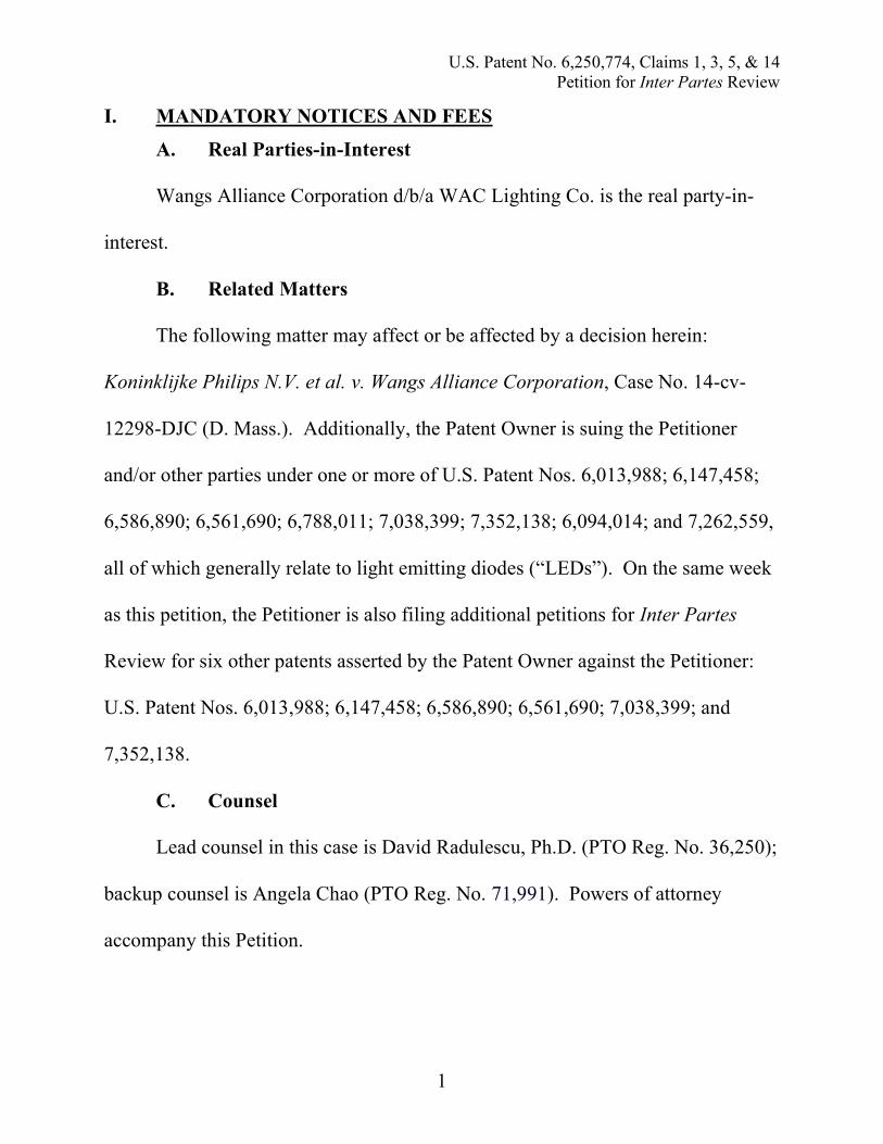
I. MANDATORY NOTICES AND FEES
A. Real Parties-in-Interest
Wangs Alliance Corporation d/b/a WAC Lighting Co. is the real party-in-
interest.
B. Related Matters
The following matter may affect or be affected by a decision herein:
Koninklijke Philips N.V. et al. v. Wangs Alliance Corporation, Case No. 14-cv-
12298-DJC (D. Mass.). Additionally, the Patent Owner is suing the Petitioner
and/or other parties under one or more of U.S. Patent Nos. 6,013,988; 6,147,458;
6,586,890; 6,561,690; 6,788,011; 7,038,399; 7,352,138; 6,094,014; and 7,262,559,
all of which generally relate to light emitting diodes (“LEDs”). On the same week
as this petition, the Petitioner is also filing additional petitions for Inter Partes
Review for six other patents asserted by the Patent Owner against the Petitioner:
U.S. Patent Nos. 6,013,988; 6,147,458; 6,586,890; 6,561,690; 7,038,399; and
7,352,138.
C. Counsel
Lead counsel in this case is David Radulescu, Ph.D. (PTO Reg. No. 36,250);
backup counsel is Angela Chao (PTO Reg. No. 71,991). Powers of attorney
accompany this Petition.

U.S. Patent No. 6,250,774, Claims 1, 3, 5, & 14Petition for Inter Partes Review
2
D. Service Information
Email: [email protected]; [email protected]
Address: Radulescu LLP, The Empire State Building, 350 Fifth Avenue,
Suite 6910, New York, NY 10118
Telephone: (646) 502-5950 Facsimile: (646) 502-5959
Please direct all correspondence to lead counsel at the above address. The
Petitioner consents to email service at the above address.
E. Payment
Under 37 C.F.R § 42.103(a), the Office is authorized to charge the fee set
forth in 37 C.F.R. § 42.15(a) to Deposit Account No. 506352 as well as any
additional fees that might be due in connection with this Petition.
II. CERTIFICATION OF GROUNDS FOR STANDING
The Petitioner certifies pursuant to 37 C.F.R § 42.104(a) that the patent for
which review is sought is available for inter partes review and that the Petitioner
is not barred or estopped from requesting an inter partes review challenging the
patent claims on the grounds identified in this Petition.
III. OVERVIEW OF CHALLENGE AND RELIEF REQUESTED
Pursuant to Rules 42.22(a)(1) and 42.104(b)(1)-(2), the Petitioner challenges
claims 1, 3, 5, and 14 of U.S. Patent No. 6,250,774 (the “’774 patent”) (Ex. 1001).
A. Prior Art Patents and Printed Publications
The Petitioner relies upon the patents and printed publications listed in the

U.S. Patent No. 6,250,774, Claims 1, 3, 5, & 14Petition for Inter Partes Review
3
Table of Exhibits, including:
1. U.S. Patent No. 5,803,579 to Turnbull, et al., (“Turnbull” (Ex. 1003)),
which is prior art under § 102(e).
2. F.A Kish, et al., High luminous flux semiconductor wafer-bonded
AlGaInP/GaP large-area emitters, 30 (21) Elecs. Letters 1790 (Oct. 13,
1994), (“Kish” (Ex. 1004)), which is prior art at least under § 102(b).
B. Grounds for Challenge
The Petitioner requests cancellation of claims 1, 3, 5, and 14 of the ’774
patent (“challenged claims”) as unpatentable under 35 U.S.C. § 103. This Petition,
supported by the declaration of Eric Bretschneider (“Bretschneider Decl.” (Ex.
1006)), filed herewith, demonstrates that there is a reasonable likelihood that the
Petitioner will prevail with respect to at least one challenged claim and that each
challenged claim is not patentable. See 35 U.S.C. § 314(a).
Ground 1: Claims 1, 3, 5, and 14 are obvious over Turnbull in view of Kish.
The Petitioner notes that the grounds for review in this Petition are distinct
from those asserted in a prior petition that was denied institution by the Board. JST
Performance, Inc. d/b/a Rigid Industries v. Koninklijke Philips N.V., Case IPR2014-
00874—in particular, the Kish reference relied upon in this Petition (co-authored by
F.A. Kish and 5 others; published in Electronics Letters) is different from the
publication co-authored by Kish (and 12 others and published in Applied Physics

U.S. Patent No. 6,250,774, Claims 1, 3, 5, & 14Petition for Inter Partes Review
4
Letters) that is referenced in the aforementioned proceeding. In the JST
Perfomrance v. Koninklijke Philips petition, the referenced publication by Kish was
F.A. Kish, et al., Very high-efficiency semiconductor wafer-bonded transparent-
substrate (AlxGa1-x)0.5In0.5P/GaP light-emitting diodes, 64 (21) APPL. PHYS. LETTERS
2839 (May 23, 1994), which is attached as Exhibit 1005 hereto for the Board’s
reference.
IV. CLAIM CONSTRUCTION
A claim in inter partes review is given the “broadest reasonable construction
in light of the specification in which it appears.” 37 C.F.R. § 42.100(b). The
broadest reasonable construction is the broadest reasonable interpretation of the
claim language. See In re Yamamoto, 740 F.2d 1569, 1571-72 (Fed. Cir. 1984).
Any claim term which lacks a definition in the specification is therefore also given a
broad interpretation. In re ICON Health & Fitness, Inc., 496 F.3d 1374, 1379 (Fed.
Cir. 2007).1 Should the Patent Owner contend that the claims have a construction
different from their broadest reasonable construction in order to avoid the prior art,
1 Petitioner adopts the “broadest reasonable construction” standard as required by
the governing regulations. 37 C.F.R. § 42.100(b). Petitioner reserves the right to
pursue different constructions in a district court, where a different standard is
applicable.

U.S. Patent No. 6,250,774, Claims 1, 3, 5, & 14Petition for Inter Partes Review
5
the appropriate course is for the Patent Owner to seek to amend the claims to
expressly correspond to its contentions in this proceeding. See Office Patent Trial
Practice Guide, 77 Fed. Reg. 48756, 48764 (Aug. 14, 2012).
A. “Luminaire”
The broadest reasonable construction of “luminaire” in the ‘774 patent is a
“lighting device.” This construction is supported by the specification of the ‘774
patent, which describes a luminaire as a device where “the light generated by the
light source is utilized more efficiently.” ‘774 patent, 1:31-33 (Ex. 1001). It is also
supported by the description of a luminaire in the “Background of the Invention”
section as “comprising a housing with a light emission window, and at least one
lighting module for illuminating an object accommodated in the housing and
comprising a light source and optical means.” ‘774 patent 1:4-7 (Ex. 1001).
Indeed, all figures in the ‘774 patent depicting a “luminaire” are further shown to be
lighting devices. See ‘774 patent, 5:36-49; 7:13-30; 7:31-8:2; 8:9-12; 8:38-67 (Ex.
1001).
B. “Lighting module”
The broadest reasonable construction of the term “lighting module” is “set of
lighting units.” The specification of the ‘774 patent supports this construction
through its description of a lighting module—“[a]ccording to the invention, the
lighting module comprises a set, for example a few dozen, of lighting units.” ‘774
U.S. Patent No. 6,250,774, Claims 1, 3, 5, & 14Petition for Inter Partes Review
6
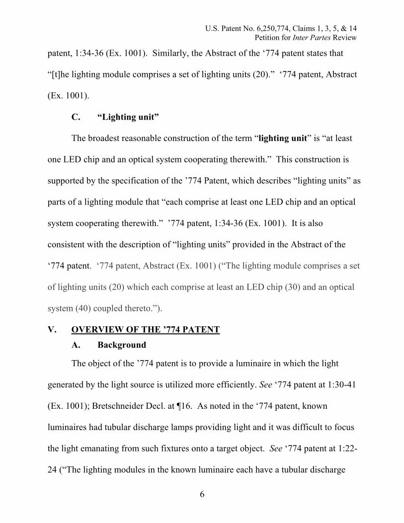
patent, 1:34-36 (Ex. 1001). Similarly, the Abstract of the ‘774 patent states that
“[t]he lighting module comprises a set of lighting units (20).” ‘774 patent, Abstract
(Ex. 1001).
C. “Lighting unit”
The broadest reasonable construction of the term “lighting unit” is “at least
one LED chip and an optical system cooperating therewith.” This construction is
supported by the specification of the ’774 Patent, which describes “lighting units” as
parts of a lighting module that “each comprise at least one LED chip and an optical
system cooperating therewith.” ’774 patent, 1:34-36 (Ex. 1001). It is also
consistent with the description of “lighting units” provided in the Abstract of the
‘774 patent. ‘774 patent, Abstract (Ex. 1001) (“The lighting module comprises a set
of lighting units (20) which each comprise at least an LED chip (30) and an optical
system (40) coupled thereto.”).
V. OVERVIEW OF THE ’774 PATENT
A. Background
The object of the ’774 patent is to provide a luminaire in which the light
generated by the light source is utilized more efficiently. See ‘774 patent at 1:30-41
(Ex. 1001); Bretschneider Decl. at ¶16. As noted in the ‘774 patent, known
luminaires had tubular discharge lamps providing light and it was difficult to focus
the light emanating from such fixtures onto a target object. See ‘774 patent at 1:22-
24 (“The lighting modules in the known luminaire each have a tubular discharge

U.S. Patent No. 6,250,774, Claims 1, 3, 5, & 14Petition for Inter Partes Review
7
lamp as the light source and a reflector as the optical means. A disadvantage of
such a luminaire is that the light from the light sources is difficult to concentrate
into a beam.”) (Ex. 1001); Bretschneider Decl. at ¶16. It was difficult to concentrate
the light emanated from previously known luminaires into a beam directed at an
object intended to be illuminated—the ‘774 patent reports that more than 50% of a
tubular lamp’s light output would often be incident outside the object intended to be
illuminated in the known luminaire designs. ‘774 patent at 1:24-27 (Ex. 1001);
Bretschneider Decl. at ¶16.
B. Summary of Alleged Invention of the ’774 Patent
The ’774 patent describes luminaires that include multiple “lighting units”
arranged within one or more “lighting modules” within a housing. Within each of
the “lighting units,” there are one or more LED chips and an optical system such
that, during operation of the luminaire, the “lighting units” illuminate different
portions of an object. See ‘774 patent at 1:49-56 (Ex. 1001); Bretschneider Decl. at
¶17. Moreover, the ‘774 patent discloses that each of the LED chips in the
luminaire provide a luminous flux of at least 5 lm during operation. See ‘774 patent
at 1:34-41 (Ex. 1001); Bretschneider Decl. at ¶17.
According to the ‘774 patent, the luminaire described in the ‘774 patent may
incorporate LED chips made of different semiconductor materials, such as AlInGaP
or InGaN. See ‘774 patent at 1:42-43 (Ex. 1001); Bretschneider Decl. at ¶18.

U.S. Patent No. 6,250,774, Claims 1, 3, 5, & 14Petition for Inter Partes Review
8
Additionally the LED chips described in the ‘774 patent have surface areas varying
from “the order of a few tenths of a mm2 up to a few mm2.” ‘774 patent at 1:49 (Ex.
1001); Bretschneider Decl. at ¶18. The ‘774 patent states that this size range for the
surface area of the active layer of an LED chip is “comparatively small.” ‘774
patent at 1:47-49 (Ex. 1001); Bretschneider Decl. at ¶18. The LED chips disclosed
in the ‘774 patent are further described as “each supply[ing] a luminous flux of at
least 5 lm during operation.” ‘774 patent at 1:57-59 (Ex. 1001).
The ‘774 patent contemplates a number of potential applications for the
luminaire disclosed therein, including “street lighting, spotlighting, or
floodlighting.” ‘774 patent at 1:60-62 (Ex. 1001); Bretschneider Decl. at ¶19.
Further, the ‘774 patent contemplates that the claimed luminaire could incorporate
LED chips that all emit the same color of light (i.e., all of the chips emit at the same
wavelength) or that the claimed luminaire could emit different colors of light (i.e.,
some of the LED chips emit at different wavelengths than others), depending on the
desired lighting effect and intended application. See ‘774 patent at 2:30-53 (Ex.
1001); Bretschneider Decl. at ¶19.
C. Prosecution History
The ’774 patent stems from European Patent Office application No.
97200149, filed on January 23, 1997. During the prosecution of the ’774 Patent,
original claims 1-13, 15, and 16 were subjected to an election requirement. PH
U.S. Patent No. 6,250,774, Claims 1, 3, 5, & 14Petition for Inter Partes Review
9
7/9/99 Office Action (Ex. 1002). The applicant responded by electing to proceed
with the prosecution of original claims 1-4, 15, and 16. PH 7/21/99 Election of
Species (Ex. 1002). Subsequently, the Examiner disagreed that original claim 16
was directed to the same species as the other elected claims and withdrew it from
consideration. PH 11/26/99 Office Action (Ex. 1002). The Examiner also rejected
original claims 1-4 as indefinite under 35 U.S.C. § 112, obvious under 35 U.S.C. §
103(a) over U.S. Patent No. 5,893,633 to Uchio (“Uchio”) in view of U.S. Patent
No. 5,105,199 to Smith (“Smith”), obvious under 35 U.S.C. § 103(a) over U.S.
Patent No. 5,5880,156 to Suzuki (“Suzuki”) in view of Smith, obvious under 35
U.S.C. § 103(a) over Suzuki in view of U.S. Patent No. 4,698,930 to Sakai
(“Sakai”). PH 11/26/99 Office Action (Ex. 1002). Upon an amendment following
the rejection, original claims 1-13, 15 and 16 were rejected as indefinite under 35
U.S.C. § 112, and the Examiner noted that non-elected original claims should be
cancelled before the application could issue. PH 4/11/00 Office Action (Ex. 1002).
In response, the applicant amended the claims and claims 1-13, 15, and 16 were
allowed. PH 6/7/00 Office Action (Ex. 1002). None of the prior art relied upon
here was of record during the prosecution of the ’774 patent.
VI. OVERVIEW OF THE PRIMARY PRIOR ART REFERENCES
A. Summary of the Prior Art

U.S. Patent No. 6,250,774, Claims 1, 3, 5, & 14Petition for Inter Partes Review
10
As shown below, there is nothing new or non-obvious in the Patent Owner’s
claims. The claimed luminaire and lighting system in the ‘774 patent were well
known. Bretschneider Decl. ¶ 24 (Ex. 1006).
B. Overview of Turnbull (Ex. 1003)
1. U.S. Patent No. 5,803,579 to Turnbull, filed on Jun. 13, 1996, is a prior
art reference to the ’774 patent under 35 U.S.C. § 102(e). Turnbull seeks to solve
the problem of efficiently illuminating objects to enhance visibility in low light level
environments by incorporating multiple LEDs into a single illuminator assembly.
See Turnbull, Exhibit 1003 at 1:12-22; Bretschneider Decl. at ¶ 52. In particular,
Turnbull discloses an improved illuminator wherein multiple LED chips and
multiple optical components are provided within a single housing to function as an
illuminator. See Turnbull, Exhibit 1003 at Fig. 1; 7:66-8:7; Bretschneider Decl. at ¶
52. Turnbull further specifically notes that light emitted from different color LEDs
may be projected such that their light beams overlap on the object(s) illuminated to
create white-light illumination by color mixing. See, e.g., Turnbull, Ex. 1003 at
7:66-8:7; 20:40-21:4; Bretschneider Decl. at ¶ 52. Turnbull also discloses the
desirability of using individual LED chips with high luminous intensity and efficacy
in the disclosed illuminator. See, e.g., Turnbull, Ex. 1003 at 5:63-66; 7:19-24; 7:66-
8:7; 21:1-40; Bretschneider Decl. at ¶ 52.

U.S. Patent No. 6,250,774, Claims 1, 3, 5, & 14Petition for Inter Partes Review
11
C. Overview of Kish (Ex. 1004)
F.A Kish, et al., High luminous flux semiconductor wafer-bonded
AlGaInP/GaP large-area emitters, 30 (21) Elecs. Letters 1790 (Oct. 13, 1994), is a
prior art reference to the ’774 patent under 35 U.S.C. § 102(b). Kish discloses
significant improvements in the luminous efficiencies of wafer-bonded
AlGaInP/GaP LED chips. Bretschneider Decl. at ¶ 53. In particular, Kish discloses
that luminous fluxes of 84 lumen (lm) were measured under DC operation of wafer-
bonded transparent-substrate AlGaInP/GaP large-area LEDs. See Kish, Ex. 1004 at
1791; Bretschneider Decl. at ¶ 53. Figure 1 of Kish discloses that the high luminous
flux LEDs are within a complete LED package including an epoxy dome, a copper
submount, package body (TO-66 header), and a heat sink. Bretschneider Decl. at ¶
53.

U.S. Patent No. 6,250,774, Claims 1, 3, 5, & 14Petition for Inter Partes Review
12
As Turnbull explains, “it is desirable to provide a highly reliable, low-
voltage, long-lived LED illuminator capable of producing white light with sufficient
luminous intensity to illuminate subjects of interest well enough to be seen and to
U.S. Patent No. 6,250,774, Claims 1, 3, 5, & 14Petition for Inter Partes Review
13
have sufficient apparent color and contrast so as to be readily identifiable.”
Turnbull, Ex. 1003 at 7:19-24; Bretschneider Decl. at ¶ 54. Turnbull further notes
that LEDs with “very high luminous efficacy in terms of light emitted compared to
electrical power consumed” are desirable for inclusion of the architecture described
in therein. Turnbull, Ex. 1003 at 21:34-35; Bretschneider Decl. at ¶ 54. The LEDs
disclosed by Kish exhibit high luminous efficiency and luminous flux—the LED
chips in Kish emit 84 lumens under DC power while current is being ramped to 8
Amps. Kish, Ex. 1004 at 1791; Bretschneider Decl. at ¶ 54. The LEDs disclosed in
Kish have high luminous flux and may be employed to illuminate an object with
their amber light (emitted wavelength for Kish LED chips is approx. 602-614 nm,
depending on DC drive current). Kish Ex. 1004 at 1791, Fig. 3; Bretschneider Decl.
at ¶ 54. Consequently, a PHOSITA would be motivated to combine the high
luminous flux LED chips disclosed in Kish with the lighting device structure
disclosed in Turnbull. Bretschneider Decl. at ¶ 54. Such a combination renders
claims of the ‘774 patent obvious, as described in element-by-element detail below.
VII. SPECIFIC GROUNDS FOR PETITION
Pursuant to Rule 42.104(b)(4)-(5), the below section, and as confirmed in the
Declaration of Eric Bretschneider, Ph.D. (Ex. 1006), demonstrate in detail how the
prior art discloses each and every limitation of claims 1, 3, 5, and 14 of the ’774
patent, and how those claims are rendered obvious by the prior art.

U.S. Patent No. 6,250,774, Claims 1, 3, 5, & 14Petition for Inter Partes Review
14
A. Ground 1: Claims 1, 3, 5, and 14 Are Obvious over Turnbull inView of Kish
1. Independent Claim 1
(a) The preamble: “[a] luminaire comprising:”
Turnbull teaches a luminaire, or lighting device, as described in Claim 1 of
the ‘774 patent. Bretschneider Decl. at ¶ 55. Specifically Turnbull discloses an
“illuminator assembly” with a plurality of LEDs that emit light when in operation.
Turnbull, Ex. 1003 at 7:27-32; Bretschneider Decl. at ¶ 55. The illuminator
assembly described in Turnbull is a device that incorporates “a plurality of light
emitting diodes on a support member to provide a light-weight, robust illuminator.”
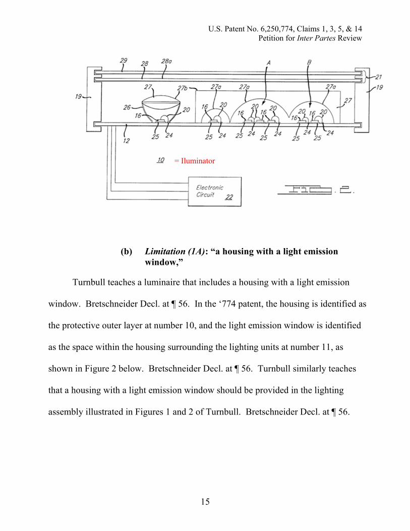
Turnbull, Ex. 1003 at 63-65; Bretschneider Decl. at ¶ 55. Figures 1 and 2 of
Turnbull illustrate the lighting device, or luminaire, described by Turnbull.
= Iluminator
U.S. Patent No. 6,250,774, Claims 1, 3, 5, & 14Petition for Inter Partes Review
15
(b) Limitation (1A): “a housing with a light emissionwindow,”
Turnbull teaches a luminaire that includes a housing with a light emission
window. Bretschneider Decl. at ¶ 56. In the ‘774 patent, the housing is identified as
the protective outer layer at number 10, and the light emission window is identified
as the space within the housing surrounding the lighting units at number 11, as
shown in Figure 2 below. Bretschneider Decl. at ¶ 56. Turnbull similarly teaches
that a housing with a light emission window should be provided in the lighting
assembly illustrated in Figures 1 and 2 of Turnbull. Bretschneider Decl. at ¶ 56.
= Iluminator

U.S. Patent No. 6,250,774, Claims 1, 3, 5, & 14Petition for Inter Partes Review
16
‘774 patent Figure 2(red emphasis added to indicate light emission window)
Turnbull Figure 1(red emphasis added to indicate light emission window)

U.S. Patent No. 6,250,774, Claims 1, 3, 5, & 14Petition for Inter Partes Review
17
Turnbull Figure 2(red emphasis added to indicate light emission window)
(c) Limitation (1B): “at least one lighting module in saidhousing for illuminating an object outside saidhousing”
Turnbull teaches a luminaire with at least one lighting module in said housing
for illuminating an object outside said housing. Bretschneider Decl. at ¶ 57. A
“lighting module,” according to the ‘774 patent, is a set of lighting units, and a
“lighting unit” is at least one LED chip and a primary optical system cooperating
therewith. Thus, Figure 1 of Turnbull illustrates a luminaire with five lighting units
depicted that may together serve as a lighting module. Bretschneider Decl. at ¶ 57.
Turnbull further discloses that the LEDs in this lighting module may be “aligned or
otherwise focused on a common spot at some predetermined distance away from the

U.S. Patent No. 6,250,774, Claims 1, 3, 5, & 14Petition for Inter Partes Review
18
illuminator.” Turnbull, Ex. 1003 at 11:4-6; Bretschneider Decl. at ¶ 57. Thus,
Turnbull discloses a lighting module that will illuminate an object outside the
housing. Bretschneider Decl. at ¶ 57.
Turnbull Figure 1(Red emphasis added to indicate the set of lighting units within the
lighting module)
(d) Limitation (1C): “the lighting module comprising a setof lighting units, each of said lighting units comprisingat least one LED chip and an optical system configuredto illuminate portions of the object during operation,”
Turnbull teaches a set of lighting units within the lighting module, where each
lighting unit comprises at least one LED chip (item 16 in Figure 1 of Turnbull) and

U.S. Patent No. 6,250,774, Claims 1, 3, 5, & 14Petition for Inter Partes Review
19
an optical system cooperating therewith (e.g., items 26, 27, and 27b in Figure 1 of
Turnbull). Bretschneider Decl. at ¶ 58. Specifically, Turnbull teaches that the
individual LED chips are disposed within optical systems including an enclosure
(18) that also acts as an integral optical element, such as a lens (27), deviator (28),
diffuser (29), or reflector (26). Turnbull, Ex. 1003 at 11:49-51; 12:61-13:3;
Bretschneider Decl. at ¶ 58. Turnbull further discloses that the optical system may
include lenslets with various different structures, including Total Internal Reflection
(TIR) collimating lenses, Plano-convex lenses, bi-convex lenses, aspheric lenses,
Fresnel lenses, catadioptric or holographic optic elements (HOE). Turnbull Ex.
1003 at 13:35-47; Bretschneider Decl. at ¶ 58. Indeed, Turnbull discloses
combinations of these disclosed optical systems as necessary and as would be
known to one of ordinary skill in the art. Turnbull, Ex. 1003 at 14:42-60;
Bretschneider Decl. at ¶ 58. The optical systems disclosed in Turnbull are
configured to direct the light emitted by the LED to illuminate portions of the
object. Turnbull, Ex. 1003 at 11:4-6; Bretschneider Decl. at ¶ 58.

U.S. Patent No. 6,250,774, Claims 1, 3, 5, & 14Petition for Inter Partes Review
20
Turnbull Figure 1
(e) Limitation (1D): “output terminals for coupled tooutput means of said converter for connecting saidcircuit arrangement to the semiconductor light source”
Turnbull explains that “preferred types of LEDs for the present invention
have very high luminous efficacy in terms of light emitted compared to electrical
power consumed.” Turnbull, Ex. 1003 at 21:33-35; Bretschneider Decl. at ¶ 59. A
person of ordinary skill in the art would be aware that luminous efficacy is defined
the ratio of luminous flux to power and that the units of luminous efficacy are
lumens per watt (lm/W). Bretschneider Decl. at ¶ 59. The LEDs disclosed in Kish
have very high luminous flux and, therefore, very high luminous efficacy—thus, a
U.S. Patent No. 6,250,774, Claims 1, 3, 5, & 14Petition for Inter Partes Review
21
person of ordinary skill in the art would appreciate that the LED chips disclosed in
Kish do not require significant electrical power to produce their high luminous flux.
Bretschneider Decl. at ¶ 59. Thus, a person having ordinary skill in the art would be
motivated to combine the LED lamp architecture disclosed in Turnbull with the
LEDs disclosed in Kish. Bretschneider Decl. at ¶ 59.
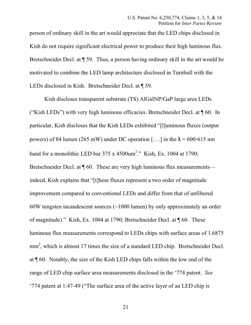
Kish discloses transparent substrate (TS) AlGaINP/GaP large area LEDs
(“Kish LEDs”) with very high luminous efficacies. Bretschneider Decl. at ¶ 60. In
particular, Kish discloses that the Kish LEDs exhibited “[l]uminous fluxes (output
powers) of 84 lumen (265 mW) under DC operation [. . .] in the = 600-615 nm
band for a monolithic LED bar 375 x 4500um2.” Kish, Ex. 1004 at 1790;
Bretschneider Decl. at ¶ 60. These are very high luminous flux measurements—
indeed, Kish explains that “[t]hese fluxes represent a two order of magnitude
improvement compared to conventional LEDs and differ from that of unfiltered
60W tungsten incandescent sources (~1000 lumen) by only approximately an order
of magnitude).” Kish, Ex. 1004 at 1790; Bretschneider Decl. at ¶ 60. These
luminous flux measurements correspond to LEDs chips with surface areas of 1.6875
mm2, which is almost 17 times the size of a standard LED chip. Bretschneider Decl.
at ¶ 60. Notably, the size of the Kish LED chips falls within the low end of the
range of LED chip surface area measurements disclosed in the ‘774 patent. See
‘774 patent at 1:47-49 (“The surface area of the active layer of an LED chip is
U.S. Patent No. 6,250,774, Claims 1, 3, 5, & 14Petition for Inter Partes Review
22
comparatively small, for example of the order of a few tenths of a mm2 up to a few
mm2.”); Bretschneider Decl. at ¶ 60.
The Kish LEDs exhibit a luminous flux of 84 lumens at 7 A input current
(7,000 mA). Kish, Ex. 1004 at 1791; Bretschneider Decl. at ¶ 61. However, Kish
discloses that the Kish LEDs will exhibit luminous flux in excess of 5 lumens even
when DC drive current is lower. Bretschneider Decl. at ¶ 61. A person of ordinary
skill in the art would understand that to a first approximation the relationship
between luminous flux and DC drive current is linear. Bretschneider Decl. at ¶ 61.
A PHOSITA would also understand that assuming a linear relationship based on
maximum output would actually underestimate the luminous flux at lower currents.
Bretschneider Decl. at ¶¶ 61-68.
In light of the luminous flux calculations detailed in Paragraphs 61-68 of the
Bretschneider declaration, it is clear that a person of ordinary skill in the art would
be motivated to combine the high luminous flux and high luminous efficacy LEDs
of Kish with the LED lamp architecture of Turnbull. See Bretschneider Decl. at ¶¶
61-69. Kish discloses amber LEDs that exhibit luminous flux in excess of 5 lumens
when in operation with a DC drive current of 0.321 Amps is applied. See
Bretschneider Decl. at ¶¶ 61-69. Indeed, the Kish LEDs have 16.39 lumens of
luminous flux in operation at 1 Amp (DC current) and are disclosed to show up to
84 lumens of luminous flux in non-equilibrium operating conditions when current is
U.S. Patent No. 6,250,774, Claims 1, 3, 5, & 14Petition for Inter Partes Review
23
at 7 Amps (during a non-equiplibrium current ramp to 8 Amp in less than 3
seconds). Kish, Ex. 1004 at 1791; Bretschneider Decl. at ¶¶ 61-69. 1 Amp of DC
current is a typical amount of current that a person of ordinary skill would expect to
when operating an LED street lamp or floodlight. Bretschneider Decl. at ¶ 69.
Depending on the heat sink, a PHOSITA would expect up to about 1-3 W of
electrical input per LED in a street lamp or floodlight. Bretschneider Decl. at ¶ 69.
Given that AlInGaP LEDs have a typical forward voltage of about 2.1 V, this would
suggest up to 1.4-1.5 A current input, which would have the Kish LEDs illuminating
well within the linear region and over 5 lm of luminous flux. Bretschneider Decl. at
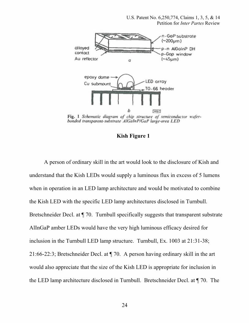
¶ 69. Additionally, Kish discloses an LED package structure with an integrated
epoxy dome, copper submount and a TO-66 header, mounted on a heat sink in such
a manner that would allow it to be easily incorporated into an LED lamp or other
device. Kish, Ex. 1004 at 1791, Fig. 1; Bretschneider Decl. at ¶ 69.
U.S. Patent No. 6,250,774, Claims 1, 3, 5, & 14Petition for Inter Partes Review
24
Kish Figure 1
A person of ordinary skill in the art would look to the disclosure of Kish and
understand that the Kish LEDs would supply a luminous flux in excess of 5 lumens
when in operation in an LED lamp architecture and would be motivated to combine
the Kish LED with the specific LED lamp architectures disclosed in Turnbull.
Bretschneider Decl. at ¶ 70. Turnbull specifically suggests that transparent substrate
AlInGaP amber LEDs would have the very high luminous efficacy desired for
inclusion in the Turnbull LED lamp structure. Turnbull, Ex. 1003 at 21:31-38;
21:66-22:3; Bretschneider Decl. at ¶ 70. A person having ordinary skill in the art
would also appreciate that the size of the Kish LED is appropriate for inclusion in
the LED lamp architecture disclosed in Turnbull. Bretschneider Decl. at ¶ 70. The

U.S. Patent No. 6,250,774, Claims 1, 3, 5, & 14Petition for Inter Partes Review
25
Kish LEDs are transparent substrate AlGaInP/GaP large area LEDs and,
consequently, a PHOSITA would be motivated to combine the Kish LEDs with the
Turnbull LED lamp architecture, thereby achieving the goal of high luminous flux
and efficacy. Bretschneider Decl. at ¶ 70.
While Turnbull teaches that amber LEDs may be used in combination with
blue-green LEDs to achieve white light by color mixing, a person of ordinary skill
in the art would understand that use of the amber Kish LEDs alone in the Turnbull
LED lamp architecture would yield desirable results. Bretschneider Decl. at ¶ 71.
A person of ordinary skill would be aware that many lighting applications do not
require a particular type or color tone of “white” light—indeed, Claim 1 of the ‘774
patent does not require a particular type or color tone of white light. Bretschneider
Decl. at ¶ 71. For just one example, it would have been well known to those of
ordinary skill in the art that amber colored lights could function as floodlights for
outdoor illumination tasks—Turnbull itself refers to such uses for highly saturated
yellow light. Turnbull, Ex. 1003 at 2:36-47; Bretschneider Decl. at ¶ 71. Indeed,
until just a few years ago, Low Pressure Sodium (“LPS”) lamps were the highest
efficacy light sources known (up to 180-200 lumens/W) and were commonly used
for street lighting. Bretschneider Decl. at ¶ 71. LPS lamps are almost purely
monochromatic with highly saturated yellow light emitted at about 589 nm.
Bretschneider Decl. at ¶ 71. A person of ordinary skill in the art would appreciate

U.S. Patent No. 6,250,774, Claims 1, 3, 5, & 14Petition for Inter Partes Review
26
that an LPS lamp yields highly saturated yellow light with the same chromaticity
and color rendering properties that is acceptable for street lighting applications.
Bretschneider Decl. at ¶ 71. Overall, a person having ordinary skill in the art would
be motivated to combine the amber LEDs disclosed in Kish with the LED lamp
architecture disclosed in Turnbull to create an LED lamp with a luminous flux in
excess of 5 lumens during operation. Bretschneider Decl. at ¶ 71.
2. Claim 3
(a) Limitation (3a): “A luminaire as claimed in claim 1wherein the optical system of the lighting unitscomprises a primary and a secondary optical system,”
Turnbull discloses a luminaire wherein the lighting units include both a
primary and a secondary optical system. Bretschneider Decl. at ¶ 72. For example,
Turnbull teaches a primary optical system including a polymer matrix enclosure
(18) located adjacent to the LED chip. Turnbull, Ex. 1003 at 11:18-25;
Bretschneider Decl. at ¶ 72. Turnbull also teaches a secondary optical system
comprising a reflector that is conically shaped (26) surrounding the LED chip.
Turnbull, Ex. 1003 at 12:61-13:3; Bretschneider Decl. at ¶ 72.
(b) Limitation (3b): “said primary optical system beingprovided with a primary reflector on which the LEDchip is provided and with a transparent envelope inwhich the LED chip is embedded,”
Turnbull teaches a primary optical system being provided with a primary
reflector on which the LED chip is provided and with a transparent envelope in

U.S. Patent No. 6,250,774, Claims 1, 3, 5, & 14Petition for Inter Partes Review
27
which the LED chip is embedded. Bretschneider Decl. at ¶ 73. In particular,
Turnbull teaches a “miniature reflector cup” that may be located adjacent to the
LED chip that functions as a primary reflector. Turnbull, Ex. 1003 at 11:18-20 (“a
miniature reflector cup (not shown) may also be located adjacent to chip 16 to
further improve light extraction from the device”); Bretschneider Decl. at ¶ 73.
Turnbull also teaches that the LED chip is embedded in a transparent envelope.
Turnbull, Ex. 1003 at 11:20-25 (“a clear, tinted, or slightly diffused polymer matrix
enclosure 18 is used to suspend, encapsulate, and protect the chip 16, lead frame 17,
optional reflector cup (not shown) and wire conductor 20 and to provide certain
desirable optical characteristics”); Bretschneider Decl. at ¶ 73. Turnbull further
explains that “[i]n most conventional discrete LED designs, enclosure 18 also acts
as an integral optical element such as a lens 27, deviator 28 or diffuser 29.”
Turnbull, Ex. 1003 at 11:49-51; Bretschneider Decl. at ¶ 73.

U.S. Patent No. 6,250,774, Claims 1, 3, 5, & 14Petition for Inter Partes Review
28
Turnbull Figure 1
(c) Limitation (3c): “said secondary optical system beingprovided with a secondary reflector in whosecomparatively narrow end portion the LED chip ispositioned.”
Turnbull teaches a secondary optical system being provided with a secondary
reflector in whose comparatively narrow end portion the LED chip is positioned.
Bretschneider Decl. at ¶ 74. Reflector 26 is shown in Figure 1 of Turnbull to have a
conical shape with the LED chip positioned in the narrow end portion of the cone,
as indicated by the annotations on Figure 1 of Turnbull below. Turnbull, Ex. 1003
at 12:61-13:3 (“The reflector 26, if used, is normally a conical parabolic, or

U.S. Patent No. 6,250,774, Claims 1, 3, 5, & 14Petition for Inter Partes Review
29
elliptical reflector and typically is made of metal or metal-coated molded plastic.
The purpose of the reflector 26 is to collect or assist in the collection of light emitted
by the LED chip 16 and project it toward the area to be illuminated in a narrower
and more intense beam than otherwise would occur.”); Bretschneider Decl. at ¶ 74.
Turnbull Figure 1
3. Claim 5
(a) Limitation (5a): “A luminaire as claimed in claim 1wherein the optical system of the lighting unitcomprises a transparent body with a first optical partwhich deflects the light generated by the LED chipthrough refraction”

U.S. Patent No. 6,250,774, Claims 1, 3, 5, & 14Petition for Inter Partes Review
30
Turnbull discloses a luminaire as claimed in claim 1 of the ‘774 patent
wherein the optical system of the lighting unit comprises a transparent body with a
first optical part which deflects the light generated by the LED chip through
refraction. Bretschneider Decl. at ¶ 75. Turnbull discloses that the optical system
of the lighting unit may include secondary optical elements (21) that perform
refraction on the light generated by the LED chip. Turnbull, Ex. 1003 at 13:49-63;
Bretschneider Decl. at ¶ 75. In particular, Turnbull provides that such secondary
optical elements may “comprise one or more of a lens 27, a deviator 28, and a
diffuser 29, each of which may be in conventional form or otherwise in the form of
a micro-groove Fresnel equivalent, a HOE, binary optic or TIR equivalent, or
another hybrid form.” Turnbull, Ex. 1003 at 13:59-61; Bretschneider Decl. at ¶ 75.
Turnbull also explains that “it should be understood that Plano-convex, bi-convex,
aspheric or their Fresnel, total-internal-reflection (TIR), catadioptric or holographic
optic element (HOE) equivalents are variants of lenslet 27a.” Turnbull, Ex. 1003 at
13:39-42; Bretschneider Decl. at ¶ 75. A catadiotripic optical element utilizes both
reflection and refraction, and is clearly disclosed by Turnbull as part of the optical
system for a viable lighting unit. Bretschneider Decl. at ¶ 75. A deviator (28) is
specifically described by Turnbull as being “a molded clear polycarbonate or acrylic
prism operating in refractive mode.” Turnbull, Ex. 1003 at 14:2-3; Bretschneider

U.S. Patent No. 6,250,774, Claims 1, 3, 5, & 14Petition for Inter Partes Review
31
Decl. at ¶ 75.
(b) Limitation (5b): “and a second optical part whichdeflects the light generated by the LED chip throughreflection.”
Turnbull further discloses that the optical system of the lighting unit includes
a second optical part that deflects the light generated by the LED chip through
reflection. Bretschneider Decl. at ¶ 76. Specifically, Turnbull discloses reflector
(26) that is included in the optical system surrounding the LED chip and directing
the light emanating from the LED chip. Turnbull, Ex. 1003 at 13:64-14:2 (“A
deviator 28 may be optionally mounted on or attached to the housing 19 or
otherwise attached to or made integral with the lens surface 27b and used to
conveniently steer the collimated beam in a direction oblique to the optic axis of the
lens 27 and/or reflector 26 used in the LED illuminator 10.”); Bretschneider Decl. at
¶ 76. Also, as noted above, a catadiotripic optical element utilizes both reflection
and refraction, and is clearly disclosed by Turnbull as part of the optical system for
a viable lighting unit. Turnbull, Ex. 1003 at 13:39-42; Bretschneider Decl. at ¶ 76.
Likewise, Turnbull discloses that “Plano-convex, bi-convex, aspheric or their
Fresnel, total-internal-reflection (TIR), catadioptric or holographic optic element
(HOE) equivalents are variants of lenslet 27a” and may be second optical parts in
the LED lamp. Turnbull, Ex. 1003 at 13:39-42; Bretschneider Decl. at ¶ 76.
U.S. Patent No. 6,250,774, Claims 1, 3, 5, & 14Petition for Inter Partes Review
32
Turnbull Figure 1
4. Independent Claim 14
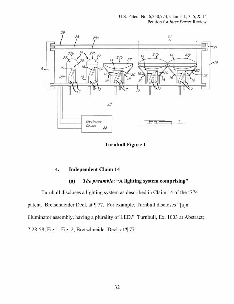
(a) The preamble: “A lighting system comprising”
Turnbull discloses a lighting system as described in Claim 14 of the ‘774
patent. Bretschneider Decl. at ¶ 77. For example, Turnbull discloses “[a]n
illuminator assembly, having a plurality of LED.” Turnbull, Ex. 1003 at Abstract;
7:28-58; Fig.1; Fig. 2; Bretschneider Decl. at ¶ 77.

U.S. Patent No. 6,250,774, Claims 1, 3, 5, & 14Petition for Inter Partes Review
33
Turnbull Figure 1
(b) Limitation (14a): “at least one luminaire comprising ahousing with a light emission window and a lightingmodule in said housing for illuminating an objectoutside of said housing”
Turnbull teaches a luminaire, or lighting device, as described in Claim 14 of
the ‘774 patent. Bretschneider Decl. at ¶ 78. Specifically Turnbull discloses an
“illuminator assembly” with a plurality of LEDs that emit light when in operation.
Turnbull, Ex. 1003 at 7:27-32; Bretschneider Decl. at ¶ 78. The illuminator
assembly described in Turnbull is a device that incorporates “a plurality of light
emitting diodes on a support member to provide a light-weight, robust illuminator.”

U.S. Patent No. 6,250,774, Claims 1, 3, 5, & 14Petition for Inter Partes Review
34
Turnbull, Ex. 1003 at 7:63-65; Bretschneider Decl. at ¶ 78. Figures 1 and 2 of
Turnbull illustrate the lighting device, or luminaire, described by Turnbull.
Bretschneider Decl. at ¶ 78.
Turnbull also teaches a luminaire that includes a housing with a light
emission window and a lighting module in said housing for illuminating an object
outside of said housing. Bretschneider Decl. at ¶ 79. In the ‘774 patent, the housing
is identified as the protective outer layer at number 10, and the light emission
window is identified as the space within the housing surrounding the lighting units
at number 11, as shown in Figure 2 below. Bretschneider Decl. at ¶ 79. Turnbull
similarly teaches that a housing with a light emission window should be provided in
the lighting assembly illustrated in Figures 1 and 2 of Turnbull. Bretschneider Decl.
at ¶ 79.
A “lighting module,” according to the ‘774 patent, is a set of lighting units,
and a “lighting unit” is at least one LED chip and a primary optical system
cooperating therewith. Bretschneider Decl. at ¶ 80. Thus Figure 1 of Turnbull
illustrates a luminaire with five lighting units depicted that may together serve as a
lighting module. Bretschneider Decl. at ¶ 80. Figure 16 of Turnbull further
discloses that LEDs may be oriented to illuminate portions of an object outside the
housing. Bretschneider Decl. at ¶ 80. Thus, Turnbull discloses a lighting module
for illuminating an object outside the housing. Bretschneider Decl. at ¶ 80.

U.S. Patent No. 6,250,774, Claims 1, 3, 5, & 14Petition for Inter Partes Review
35
‘774 patent Figure 2
Turnbull Figure 1

U.S. Patent No. 6,250,774, Claims 1, 3, 5, & 14Petition for Inter Partes Review
36
Turnbull Figure 2
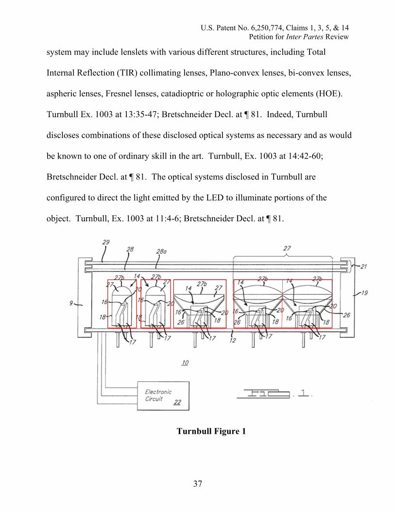
(c) Limitation (14b): “said module comprising a pluralityof lighting units each of said plurality of lighting unitscomprising at least one LED chip and an opticalsystem”
Turnbull teaches a plurality of lighting units within the lighting module,
where each lighting unit comprises at least one LED chip (item 16 in Figure 1 of
Turnbull) and an optical system cooperating therewith (items 18, 26, and 27 in
Figure 1 of Turnbull). Bretschneider Decl. at ¶ 81. Specifically, Turnbull teaches
that the individual LED chips are disposed within optical systems including an
enclosure (18) that also acts as an integral optical element, such as a lens (27),
deviator (28), diffuser (29), or reflector (26). Turnbull, Ex. 1003 at 11:49-51;
12:61-13:3; Bretschneider Decl. at ¶ 81. Turnbull further discloses that the optical
U.S. Patent No. 6,250,774, Claims 1, 3, 5, & 14Petition for Inter Partes Review
37
system may include lenslets with various different structures, including Total
Internal Reflection (TIR) collimating lenses, Plano-convex lenses, bi-convex lenses,
aspheric lenses, Fresnel lenses, catadioptric or holographic optic elements (HOE).
Turnbull Ex. 1003 at 13:35-47; Bretschneider Decl. at ¶ 81. Indeed, Turnbull
discloses combinations of these disclosed optical systems as necessary and as would
be known to one of ordinary skill in the art. Turnbull, Ex. 1003 at 14:42-60;
Bretschneider Decl. at ¶ 81. The optical systems disclosed in Turnbull are
configured to direct the light emitted by the LED to illuminate portions of the
object. Turnbull, Ex. 1003 at 11:4-6; Bretschneider Decl. at ¶ 81.
Turnbull Figure 1

U.S. Patent No. 6,250,774, Claims 1, 3, 5, & 14Petition for Inter Partes Review
38
(d) Limitation (14c): “said LED chips each supplying aluminous flux of at least 5 lm during operation, saidluminous flux being directed through a respectiveoptical system toward respective portion of saidobject.”
As explained in detail above in connection with Claim Limitation 1d and at
Paragraphs 54 and 59 to 71 of the Bretschneider Declaration, the combination of
Kish and Turnbull would disclose to one of ordinary skill in the art that each LED
chip supplies “a luminous flux of at least 5 lm during operation.” Bretschneider
Decl. at ¶¶ 54; 59 to 71.
Furthermore, Turnbull discloses that the luminous flux generated by each
LED is directed toward its respective optical system toward the respective portion of
said object. Bretschneider Decl. at ¶ 83. In particular, Figure 16 of Turnbull
illustrates how the luminous flux of each LED is directed toward respective portions
of an object outside of the lighting system. Bretschneider Decl. at ¶ 83. Thus, the
light and luminous flux emanating from each LED is directed to a portion of the
object outside the housing. Bretschneider Decl. at ¶ 83.

U.S. Patent No. 6,250,774, Claims 1, 3, 5, & 14Petition for Inter Partes Review
39
Turnbull at Figure 16
VIII. CONCLUSION
Based on the foregoing, Claims 1, 3, 5, and 14 of the ’774 patent recite
subject matter that is unpatentable. The Petitioner requests institution of an inter
partes review to cancel these claims.
U.S. Patent No. 6,250,774, Claims 1, 3, 5, & 14Petition for Inter Partes Review
40
RESPECTFULLY SUBMITTED,RADULESCU LLP
Date: May 28, 2015
The Empire State Building350 Fifth Avenue, Ste. 6910New York, NY 10118Phone: (646) 502-5950
/s/ David C. RadulescuDavid C. Radulescu, Ph.D.Attorney for Petitioner WangsAlliance Corporation d/b/a WACLighting Co.Registration No. 36,250

U.S. Patent No. 6,250,774, Claims 1, 3, 5, & 14Petition for Inter Partes Review
41
Attachment A:
CERTIFICATE OF SERVICE ON PATENTOWNER UNDER 37 C.F.R. §§ 42.6(e) and 42.105
Pursuant to 37 C.F.R. §§ 42.6(e) and 42.105, the undersigned certifies that
on May 28, 2015, a complete and entire copy of this Petition for Inter Partes
Review of U.S. Patent 6,250,774 was served via EXPRESS MAIL®, postage
prepaid, to the Patent Owner by serving the following parties:
Philips Intellectual Property & StandardsP.O. Box 3001Briarcliff Manor, NY 10510Patent owner’s correspondence address of record
Denise W. DeFrancoFinnegan, Henderson, Farabow, Garrett & Dunner, LLPTwo Seaport LaneBoston, MA 02210-2001Additional address known to Petitioner as likely to effect service
RADULESCU LLP
Dated: May 28, 2015
The Empire State Building350 Fifth Avenue, Suite 6910New York, NY 10118Phone: (646) 502-5950
/s/ David C. RadulescuDavid C. Radulescu, Ph.D.Attorney for Petitioner WangsAlliance Corporation d/b/a WACLighting Co.Registration No. 36,250

U.S. Patent No. 6,250,774, Claims 1, 3, 5, & 14Petition for Inter Partes Review
42
Attachment B: Appendix of Exhibits
Exhibit DescriptionEx. 1001 U.S. Patent No. 6,250,774 to BegemannEx. 1002 Patent History of U.S. Patent No. 6,250,774 to BegemannEx. 1003 U.S. Patent No. 5,803,579 to TurnbullEx. 1004 F.A Kish, et al., High luminous flux semiconductor wafer-bonded
AlGaInP/GaP large-area emitters, 30 (21) Elecs. Letters 1790 (Oct.13, 1994)
Ex. 1005 F.A. Kish, et al., Very high-efficiency semiconductor wafer-bondedtransparent-substrate (AlxGa1-x)0.5In0.5P/GaP light-emitting diodes, 64(21) APPL. PHYS. LETTERS 2839 (May 23, 1994)
Ex. 1006 Declaration of Eric BretschneiderEx. 1007 Curriculum Vitae of Eric Bretschneider