Embed Size (px)
Citation preview
(Page intentionally blank)
FP7-611223
Project co-funded by the European Commission under the
Information and Communication Technologies (ICT) 7th
Framework Programme
Files for Recurrent Manufacturing
Document Identifier: D4.4 Due Date: 30/10/2015
Delivery Date: 06/11/2015 Classification: Public
Editors: Josias WACKER, Olivier CHÉTELAT Rita PARADISO Laura CALDANI
Document Version: 1.0
WELCOME Wearable Sensing and Smart Cloud Computing for Integrated Care to COPD Patients with
Comorbidities
Contract Start Date: 1st November 2013 Contract Duration: 48 months
Project Partners: EXODUS (GR), CSEM (CH), KINGSTON (UK), AUTH (GR), INVENTYA (UK), CAU (DE), ROYAL COLLEGE OF SUR (IR), SMARTEX (IT), CIRO+ B.V. (NL), Kristronics GmbH (DE), UNIVERSADE DE COIM (PT), Croydon Health Servi (UK)

D4.4 – Files for Recurrent Manufacturing Page 2 of 18

D4.4 – Files for Recurrent Manufacturing Page 3 of 18
(Page intentionally blank)
D4.4 – Files for Recurrent Manufacturing Page 4 of 18
Contributors
Name Organization
Olivier CHÉTELAT CSEM
Josias WACKER CSEM
Michaël RAPIN CSEM
Christophe MEIER CSEM
Abdessamad FALHI CSEM
Etienne HÄNNI CSEM
Jacques-André PORCHET CSEM
Rita PARADISO SMARTEX
Laura CALDANI SMARTEX
Carlo MANCUSO SMARTEX
Maria PACELLI SMARTEX
Olimpia SACCHETTO SMARTEX
Roberto ORSELLI SMARTEX
Peer Reviewers
Name Organization
Andreas RAPTOPOULOS EXUS
Vassilis KILINTZIS AUTH
Ioannis KOUTRAS EXUS
Revision History
Version Date Modifications
01 14/10/2015 V1 released
0.3 04/11/2015 Corrected according to internal reviewers’ comments
1.0 06/11/2015 Submission

D4.4 – Files for Recurrent Manufacturing Page 5 of 18
Executive Summary
This report sums up the files for recurrent manufacturing of all sub-units of the WELCOME vest
system. Namely, these sub-units are the measuring sensors (type I and type V), the reference sensor
and the textile vest (with cabling and accessories such as press buttons and a zipper).
D4.4 – Files for Recurrent Manufacturing Page 6 of 18
Table of Contents
Executive Summary .................................................................................................................................. 5
1 Introduction ..................................................................................................................................... 7
2 Type V sensor ................................................................................................................................... 8
2.1 Electronic components ........................................................................................................... 8
2.2 Mechanical components ......................................................................................................... 8
3 Type I sensor .................................................................................................................................. 10
3.1 Electronical components ...................................................................................................... 10
3.2 Mechanical components (housing) ....................................................................................... 10
4 Reference Sensor ........................................................................................................................... 12
4.1 Electronical components ...................................................................................................... 12
4.1.1 Optical part PCB ................................................................................................................ 12
4.1.2 Processing part PCB .......................................................................................................... 12
4.2 Mechanical components (housing) ....................................................................................... 13
5 Textile vest ..................................................................................................................................... 14
5.1 Fabrication procedure of the vest......................................................................................... 14
5.2 Buttons .................................................................................................................................. 15
5.3 Cabling .................................................................................................................................. 16
6 Conclusions .................................................................................................................................... 17
Abbreviations ......................................................................................................................................... 18

D4.4 – Files for Recurrent Manufacturing Page 7 of 18
1 Introduction
WELCOME is a European project which aims at improving the quality of life of patients who suffer
from chronic obstructive pulmonary disease (COPD). One strategy to reach this goal is to closely
monitor several relevant health parameters of COPD patients. One part of the WELCOME system is
therefore a vest containing sensors which are in direct contact with the patients’ skin and measure
various physiological signals (e.g. electrocardiogram [ECG], activity, blood oxygen saturation [SpO2]
electrical impedance tomography [EIT] of the chest).
While D4.1 has detailed the design of the WELCOME vest, this document assembles all necessary files
for the production of all sub-systems of the WELCOME vest. These subsystems are namely:
Type I sensors
Type V sensors
Reference sensor
The textile vest
Each measuring sensor consists of an electrical part (battery and PCB with mounted electronic
components) and of a mechanical part (housing and structural elements inside the sensor housing).
Both, mechanical and electrical parts are detailed with drawings and production files. Files for
production of electrical parts were transferred to KRISTRONICS..
The vest consists of a textile part with wiring and of accessories (snap buttons and a zipper). These
items are also detailed in the respective chapter.
For reasons of confidentiality, this document does not detail every part of the vest. For each item of
the vest, we therefore list the files which are comprised in the full master document. All files are
available at request (contact [email protected]).
D4.4 – Files for Recurrent Manufacturing Page 8 of 18
2 Type V sensor
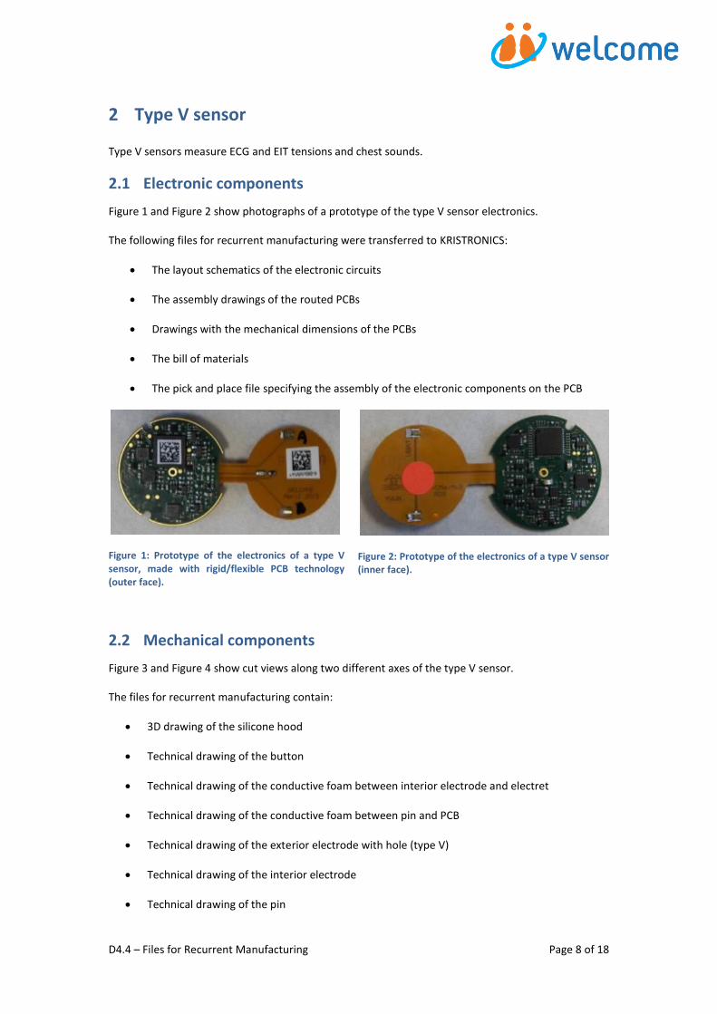
Type V sensors measure ECG and EIT tensions and chest sounds.
2.1 Electronic components
Figure 1 and Figure 2 show photographs of a prototype of the type V sensor electronics.
The following files for recurrent manufacturing were transferred to KRISTRONICS:
The layout schematics of the electronic circuits
The assembly drawings of the routed PCBs
Drawings with the mechanical dimensions of the PCBs
The bill of materials
The pick and place file specifying the assembly of the electronic components on the PCB
Figure 1: Prototype of the electronics of a type V sensor, made with rigid/flexible PCB technology (outer face).
Figure 2: Prototype of the electronics of a type V sensor (inner face).
2.2 Mechanical components
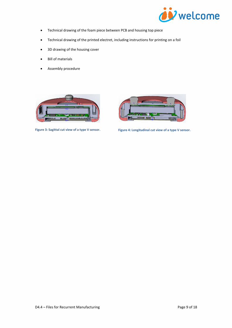
Figure 3 and Figure 4 show cut views along two different axes of the type V sensor.
The files for recurrent manufacturing contain:
3D drawing of the silicone hood
Technical drawing of the button
Technical drawing of the conductive foam between interior electrode and electret
Technical drawing of the conductive foam between pin and PCB
Technical drawing of the exterior electrode with hole (type V)
Technical drawing of the interior electrode
Technical drawing of the pin
D4.4 – Files for Recurrent Manufacturing Page 9 of 18
Technical drawing of the foam piece between PCB and housing top piece
Technical drawing of the printed electret, including instructions for printing on a foil
3D drawing of the housing cover
Bill of materials
Assembly procedure
Figure 3: Sagittal cut view of a type V sensor.
Figure 4: Longitudinal cut view of a type V sensor.
D4.4 – Files for Recurrent Manufacturing Page 10 of 18
3 Type I sensor
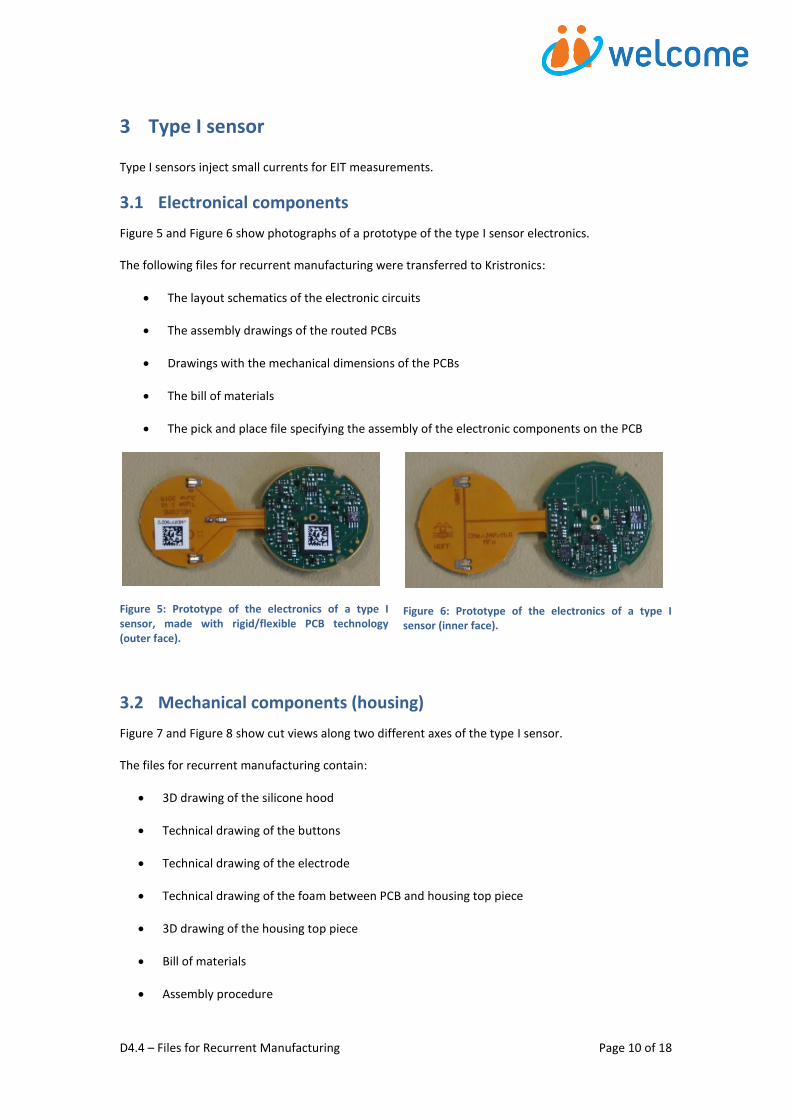
Type I sensors inject small currents for EIT measurements.
3.1 Electronical components
Figure 5 and Figure 6 show photographs of a prototype of the type I sensor electronics.
The following files for recurrent manufacturing were transferred to Kristronics:
The layout schematics of the electronic circuits
The assembly drawings of the routed PCBs
Drawings with the mechanical dimensions of the PCBs
The bill of materials
The pick and place file specifying the assembly of the electronic components on the PCB
Figure 5: Prototype of the electronics of a type I sensor, made with rigid/flexible PCB technology (outer face).
Figure 6: Prototype of the electronics of a type I sensor (inner face).
3.2 Mechanical components (housing)
Figure 7 and Figure 8 show cut views along two different axes of the type I sensor.
The files for recurrent manufacturing contain:
3D drawing of the silicone hood
Technical drawing of the buttons
Technical drawing of the electrode
Technical drawing of the foam between PCB and housing top piece
3D drawing of the housing top piece
Bill of materials
Assembly procedure

D4.4 – Files for Recurrent Manufacturing Page 11 of 18
Figure 7: Sagittal cut view of a type I sensor.
Figure 8: Longitudinal cut view of a type I sensor.
D4.4 – Files for Recurrent Manufacturing Page 12 of 18
4 Reference Sensor
4.1 Electronical components
4.1.1 Optical part PCB
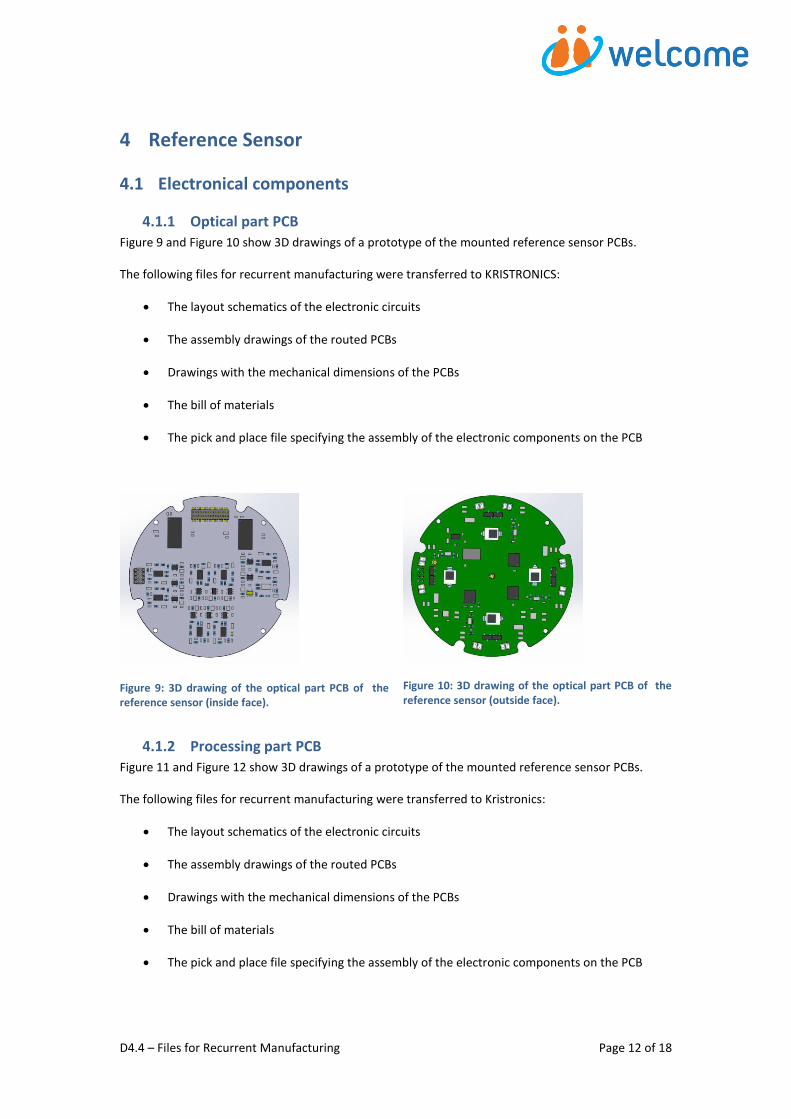
Figure 9 and Figure 10 show 3D drawings of a prototype of the mounted reference sensor PCBs.
The following files for recurrent manufacturing were transferred to KRISTRONICS:
The layout schematics of the electronic circuits
The assembly drawings of the routed PCBs
Drawings with the mechanical dimensions of the PCBs
The bill of materials
The pick and place file specifying the assembly of the electronic components on the PCB
Figure 9: 3D drawing of the optical part PCB of the reference sensor (inside face).
Figure 10: 3D drawing of the optical part PCB of the reference sensor (outside face).
4.1.2 Processing part PCB
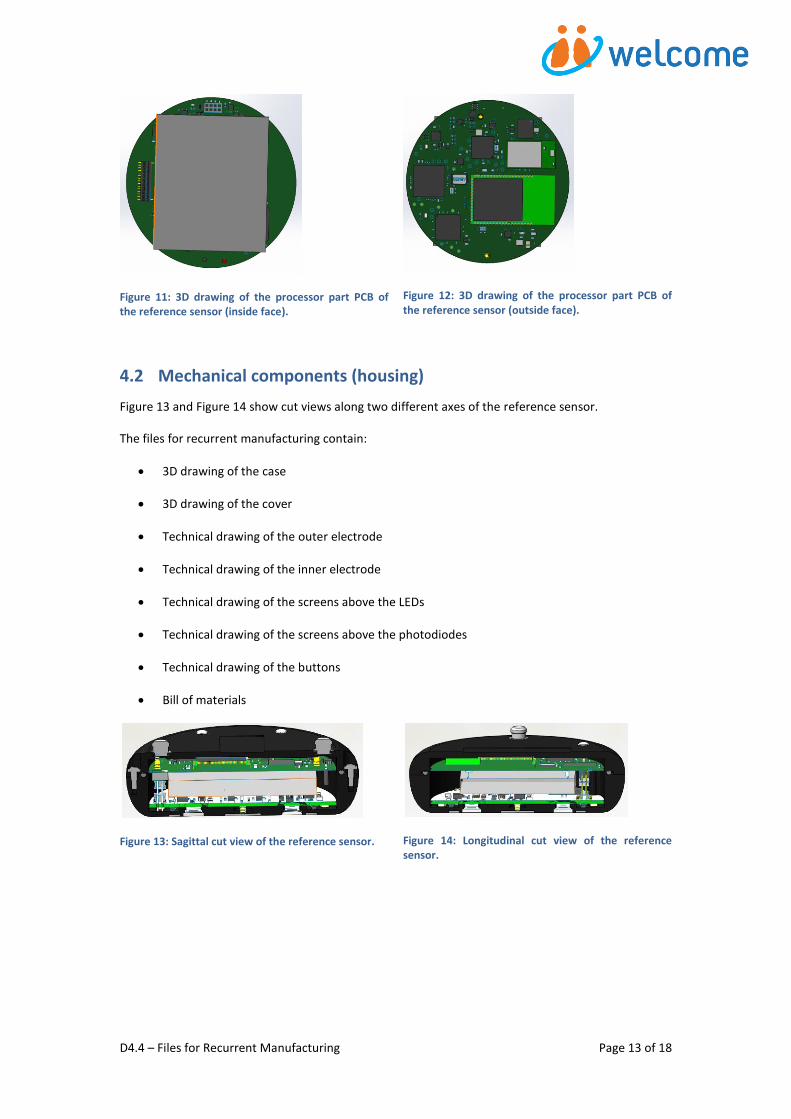
Figure 11 and Figure 12 show 3D drawings of a prototype of the mounted reference sensor PCBs.
The following files for recurrent manufacturing were transferred to Kristronics:
The layout schematics of the electronic circuits
The assembly drawings of the routed PCBs
Drawings with the mechanical dimensions of the PCBs
The bill of materials
The pick and place file specifying the assembly of the electronic components on the PCB
D4.4 – Files for Recurrent Manufacturing Page 13 of 18
Figure 11: 3D drawing of the processor part PCB of the reference sensor (inside face).
Figure 12: 3D drawing of the processor part PCB of the reference sensor (outside face).
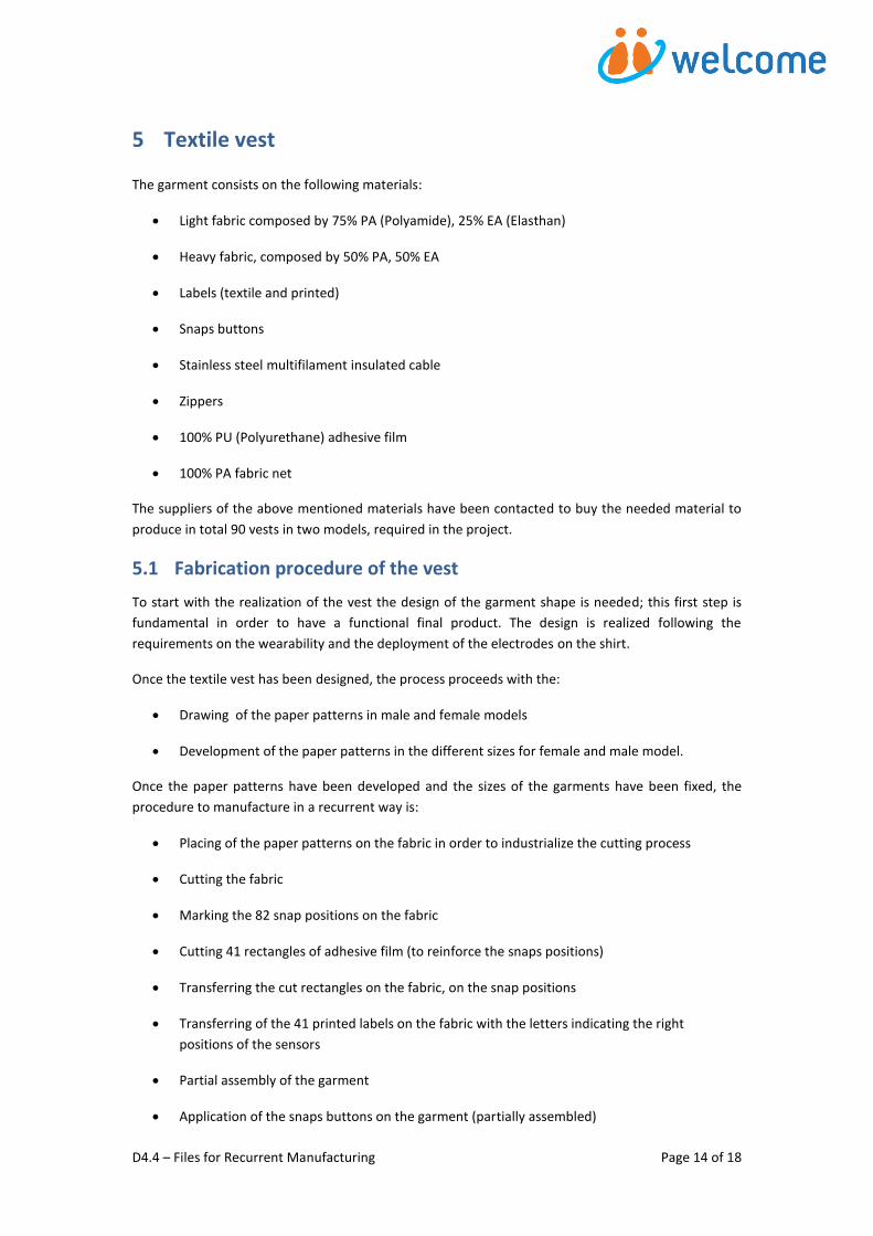
4.2 Mechanical components (housing)
Figure 13 and Figure 14 show cut views along two different axes of the reference sensor.
The files for recurrent manufacturing contain:
3D drawing of the case
3D drawing of the cover
Technical drawing of the outer electrode
Technical drawing of the inner electrode
Technical drawing of the screens above the LEDs
Technical drawing of the screens above the photodiodes
Technical drawing of the buttons
Bill of materials
Figure 13: Sagittal cut view of the reference sensor.
Figure 14: Longitudinal cut view of the reference sensor.
D4.4 – Files for Recurrent Manufacturing Page 14 of 18
5 Textile vest
The garment consists on the following materials:
Light fabric composed by 75% PA (Polyamide), 25% EA (Elasthan)
Heavy fabric, composed by 50% PA, 50% EA
Labels (textile and printed)
Snaps buttons
Stainless steel multifilament insulated cable
Zippers
100% PU (Polyurethane) adhesive film
100% PA fabric net
The suppliers of the above mentioned materials have been contacted to buy the needed material to
produce in total 90 vests in two models, required in the project.
5.1 Fabrication procedure of the vest
To start with the realization of the vest the design of the garment shape is needed; this first step is
fundamental in order to have a functional final product. The design is realized following the
requirements on the wearability and the deployment of the electrodes on the shirt.
Once the textile vest has been designed, the process proceeds with the:
Drawing of the paper patterns in male and female models
Development of the paper patterns in the different sizes for female and male model.
Once the paper patterns have been developed and the sizes of the garments have been fixed, the
procedure to manufacture in a recurrent way is:
Placing of the paper patterns on the fabric in order to industrialize the cutting process
Cutting the fabric
Marking the 82 snap positions on the fabric
Cutting 41 rectangles of adhesive film (to reinforce the snaps positions)
Transferring the cut rectangles on the fabric, on the snap positions
Transferring of the 41 printed labels on the fabric with the letters indicating the right
positions of the sensors
Partial assembly of the garment
Application of the snaps buttons on the garment (partially assembled)
D4.4 – Files for Recurrent Manufacturing Page 15 of 18
Soldering of the cable on the snap buttons (cabling)
Final assembling of the garment and finishing with the application of zippers and sewing
labels
Ironing and packaging.
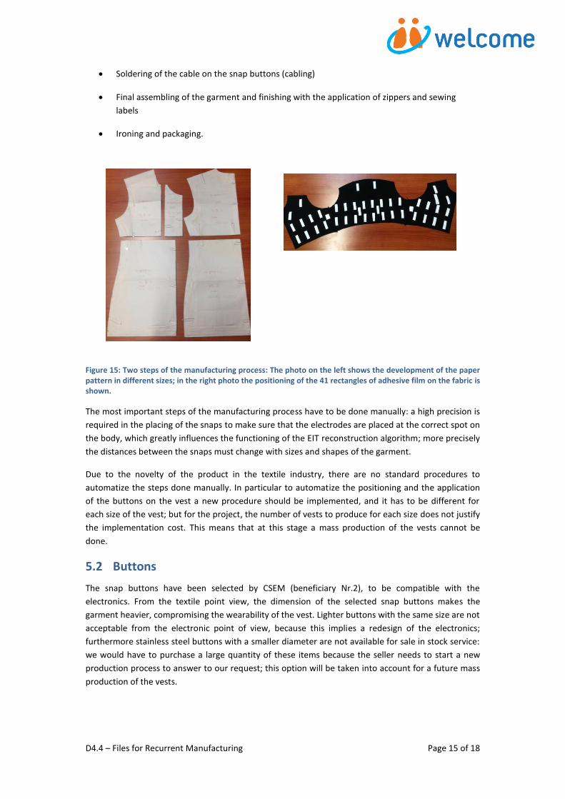
Figure 15: Two steps of the manufacturing process: The photo on the left shows the development of the paper pattern in different sizes; in the right photo the positioning of the 41 rectangles of adhesive film on the fabric is shown.
The most important steps of the manufacturing process have to be done manually: a high precision is
required in the placing of the snaps to make sure that the electrodes are placed at the correct spot on
the body, which greatly influences the functioning of the EIT reconstruction algorithm; more precisely
the distances between the snaps must change with sizes and shapes of the garment.
Due to the novelty of the product in the textile industry, there are no standard procedures to
automatize the steps done manually. In particular to automatize the positioning and the application
of the buttons on the vest a new procedure should be implemented, and it has to be different for
each size of the vest; but for the project, the number of vests to produce for each size does not justify
the implementation cost. This means that at this stage a mass production of the vests cannot be
done.
5.2 Buttons
The snap buttons have been selected by CSEM (beneficiary Nr.2), to be compatible with the
electronics. From the textile point view, the dimension of the selected snap buttons makes the
garment heavier, compromising the wearability of the vest. Lighter buttons with the same size are not
acceptable from the electronic point of view, because this implies a redesign of the electronics;
furthermore stainless steel buttons with a smaller diameter are not available for sale in stock service:
we would have to purchase a large quantity of these items because the seller needs to start a new
production process to answer to our request; this option will be taken into account for a future mass
production of the vests.
D4.4 – Files for Recurrent Manufacturing Page 16 of 18
5.3 Cabling
The cabling of the vest is not an industrializable process, due to the difficulties of the soldering: the
selected cable is an insulated stainless steel multifilament (see Error! Reference source not found. ),
the insulation has to be removed from the cable before soldering it on the top of the snap buttons.
This has to be done in for each button; moreover the thick diameter of the cable, needed to reduce its
electrical resistance, makes it more rigid than the previous one (see Error! Reference source not
found.): this makes it difficult to manage the cable between two soldering points; the consequence is
that the cabling is done manually which is time- and resource consuming.
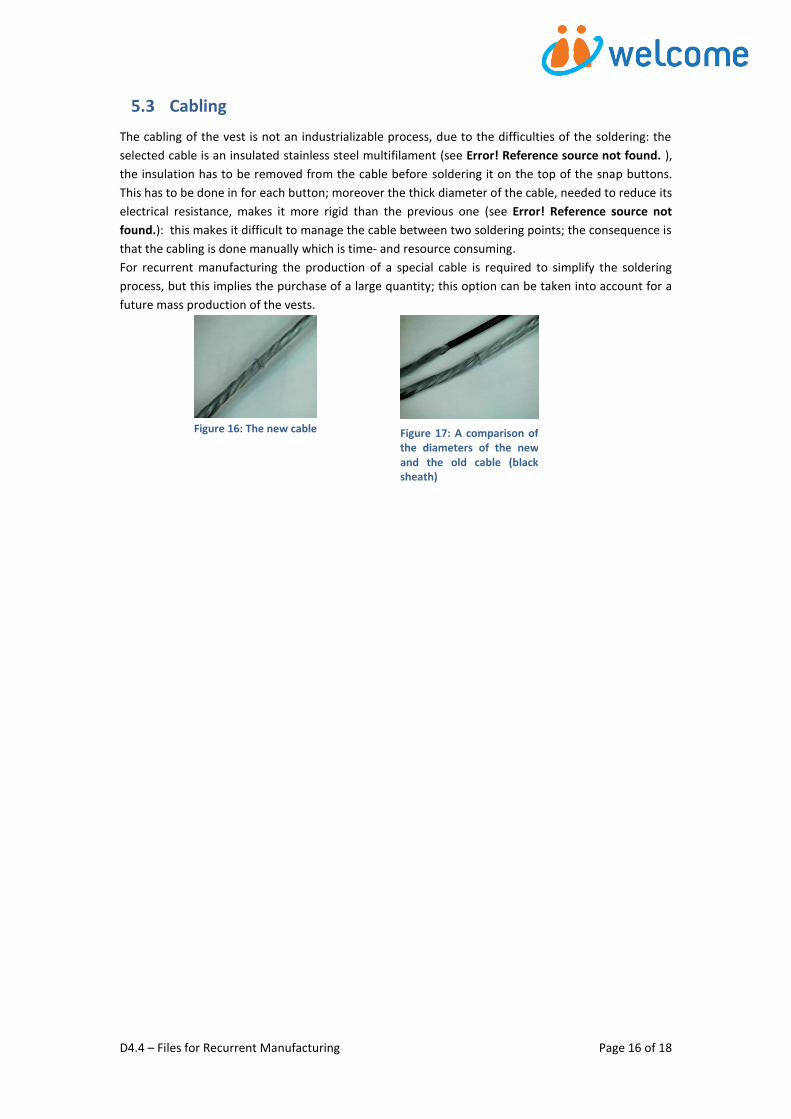
For recurrent manufacturing the production of a special cable is required to simplify the soldering
process, but this implies the purchase of a large quantity; this option can be taken into account for a
future mass production of the vests.
Figure 16: The new cable
Figure 17: A comparison of the diameters of the new and the old cable (black sheath)

6 Conclusions
In this report, we have presented the files necessary for recurrent manufacturing of the WELCOME
vest. In more detail, these files contain the mechanical design and the electrical schematics of all
components of the sensor vest. The files were sent to the partners and sub-contractors for
manufacturing analysis and have already been produced for a prototype vest. The parts are being
produced in the next 6 months. Moreover we have described the steps for the realization of the
textile vests; the final model of the vest has been developed and a final prototype has been realized;
in the next months we will start with the production of the garments foreseen in the project.

D4.4 – Files for Recurrent Manufacturing Page 18 of 18
Abbreviations
COPD: Chronic Obstructive Pulmonary Disease
ECG: Electrocardiogram (recording of the heart activity through electrodes)
EIT: Electrical Impedance Tomography (imaging procedure which is based on
the impedance of the inspected object)
EA: Elastan (synthetic material)
PA: Polyamide (synthetic material)
PCB: Princted circuit board (board on which electrical components are
connected to each other)
PU: Polyurethane (synthetic material)
SpO2: Blood oxygen saturation