Embed Size (px)
Citation preview

ED 219 653
AUTHORTITLEINSTITUTION
PUB DATENOTE
AVAILABLE FROM
EDRS PRICEDESCRIPTORS
ABSTRACT
DOCUMENT RESUME
CE 033 510
Davis, Ronald; And OthersBasic Drafting: Book One.Mid-America Vocational Curriculum Consortium,Stillwater, Okla.81512p.; For related documents see CE 033 501 and CE033 511.Mid-America Vocational Curriculum Consortium, 1515West Sixth Avenue, Stillwater, OK 74074.
MF02 Plus Postage. PC Not Available from EDRS.*Architectural Drafting; Competency Based Education;Criterion Referenced Tests; *Drafting; *EngineeringDrawing; Equipment; Equipment Utilization;Instructional Materials; Job Skills; LearningActivities; Metric System; Postsecondary Education;Safety; *Technical Education; *TechnicalIllustration
The first of a two-book course in drafting, thismanual consists of 13 topics in the following units: introduction todrafting, general safety, basic tools and lines, major equipment,applying for a job, media, lettering, reproduction, drawing sheetlayout, architect's scale usage, civil engineer's scale usage,mechanical engineer's scale usage, and metric scale usage. Includedin the individual instructional units are some or all of the
following: performance objectives, suggested activities for teachers,information sheets, assignment sheets, job sheets, visual aids,tests, and test answers. Instructional materials in the publicationare written in terms of student performance using measurableobjectives and include the content necessary for employment in anentry-level drafting occupation. (MN)
*.* 4 ; , J,*********** ******* *************** ***** *************************** Reproductions supplied by EDRS are the best that can be made *
* from the original document. *
******** ***************************************************************

1.4041Mt NT 01, ling Ilory
BASIC [)RAFT ING )0K UNE
Aor''I d Vnt C'JF
Board of flirt (
David MerriH, South DakotMerle Rudebusch, Nebraska, Vict C-
Jim Dasher, Ark.)f1SdSBill Barnes, ColoradoEd Hankins, l\arNe,
David Poston, LOLPS',311,1Anion Herd, Missouri
Bill Jackson, New Mexi«)I irr. Barnhardt North D
Bob Patton, OklithornPar I. tridley, fex
Ann BPrISCHI, Ex.ecutive DttLr'1'
AICCROF1( ONI,,A,, Pr I, I ,

COPYRIGHT 1981
Mid Arnericd Vocational Curriculum Consortium, Inc
PnnTed try
ct 4te Df=pdr !mew of Voc ational dnn Techrtc dl Enoc,ct*onStilLvater, Ol,idhOflld /40741
))

;Hi
()Pr' 0 III',I .ollIno ill a series of diati Iva tes kilt) II Ht,
toe ^1iil ArneHi a V(II al Moil LAIIHCIlitirn Cn,IiltP,Orl 1 Ii rO at ';,'%/1the bay( s necessary 'o He employ 41 in ,ha-on ; Ii 01),C,Itm
A,e1`, f ',pet rah/anon so( 0 as Mo Hnical )raton.; Ind Art Iii IThol Dr iltm,; mi mi'lm,;
supplerhcots to oe used with tins hook
Sl/C(I",S cu thic, public itum 15 tinw, It' t, It uI lu a /,' ",,, is
vVitir It`, development The techrm .11 wa 'ter, ha,e niwierons yf'tea( Plop and wr t I op experwoce Assisting them I their Hlwts «inelatn,
pint",entatives who brought with them Its Hnical tA[mrtise and writ Hi,
lassroorn and to the trade To assure that the make kik would parallel tht rio Ntr y irsi
tiinIiitrit and he accept"d as a transport Ode hay( tem,lun(1 tool, oh,ht orgaiiiiatiohs iiiimnicistry representatives were involved In the oevidownelital phases of tilt ilirlilu Amor
non is extended to them for their valuable contrioiatIons to the "lanual
This r1ohlicaticri IS designed to t101,1(, iftV01/01 ),,1 111 T1111 A, ',Hs
publicatIon IS MIZ'd, It IS hoped that the stttit'11t Pflr for aiar t",%11111,111-0Vt` arid
he ',Wile,- able to assume a role in their i lentIl Hccuparion Every ef tort ha',
11, MakI this publication basu r"adahlP, and iev ill neart,, cIsihIlt 'Put t' \,11,11 ill 1 ,of
ili-ariac non ti iVe been intentionally °mitt, 1 irr(tiVitI(nmI rts(mlIiI/lIIuil frht liicirew, il a lett to the indiviIiu I i1 Ii toh, oil OF, I I
rnis ,111111 real I mn 01 1 5 Itd1 ;)(irt .)f IP it'd( liii tll 111/1
In* lir Hindi materials ii Chi: LIP 101111 ,ilo 5511115; 0 IrS (If r[lIlt III ijec II S iS 111s I 1111115 Itlyt' IHIff i 1 to ti',1( I11111 t'l 1(
it1(111[111 it'd/111N 111111, s (.,t111111111 tarts ii t'vraktatInIrr
for thilf(trrn rlwasureluent of ',TIP Jt It 11)1111`(,`, il 11,1111,`11 II` I IHJ
liii !Pal 11''IS art ' (Hiratwii, II ni ili ntl r,f it, Li, III( H;
I.! ,11 tIlt' t'iId of 1,,t
I t i s " 1 . 011cr alitt ( i t t " ' VL,L, I I uri 011 Ili a '''r `,11,1 `11 LIII
11,11 11(1_, ,tk011
1,,, ; 1'
, II ( (;, .1 Iiit I ,'
Hi I Vii It (

PRE :\r1
Dr,i1Hrui RuHA Om, 1,, the first if two publi, dOrm ,11,0wi, Jot '
content nee essary for employment in an entry level (1raftinc, f11( unatio,.
as only one, volume, the separation of 80su [)rdf,'/Hq into 1%,,o 110)4,, A.1,, If I' TI t II ;I I to
rHuce the size of the materials The result is two books that X. 'Lot !( Orr,/ and much more convenient to vvork with
ri ,1 time when educational costs continue to se 1 lower poe eu lit \;,,;!teachers am I students alike But mote tlian that,
comp,' "rime size svi II be easier to adapt to speceducation
If'cre nos never been a MAVcr publication in to N./ (ii st /II
and educators let us know how the (WriCtill.1111 irip out in thp Lew tHipl Ttat iltrpsoonse to date has helped make the MAVCC format the most solid 111 VOC' ito nit tee mill al
education, and this new, comprehensive publication of Rasir Draffim; sinnuH ow,, Mill I,more that as roavcc, continues to publish we also contlnue to li,,ten
Ann, fie'ri',011Ez.o Dire, fipf',1H Arne,r I( .1 VI lk '

ACKNOWLEDGMETS
Appreciation is extended to those indtviduals who contributed their tune and talents in thedevelopment of Basil Drafting Book One
The contents of this publication were planned and review by
Mid America Vocational Curriculum Consortium Committc e
Bruce YanceyW H Par kisonRonald D DavisKaren SchertzRick RomanJohn H SchmeltzMilton MooreKeith LockardJames BrownThomas M PalmcrChar les E. CarhonneauWilliam PayneJoe Porter
Hunter OklahomaNatchitoches, LouisianaWayne, OkLhomaBoulder, ColoradoAustin, TexasSanta Fe, New MexicoSt Joseph, MissouriLincoln, NebraskaPine Bluff, ArkairsusDevil's Lake, North DakotaWatertown, South Dakot.Westininister , ColoradoPittslnir q, Kansas
Special dome( ration is extended to Jack Hetiwr, of the Oklahoh.a State Departn'en staff,representing state lesrel supervision, and to Tom Siltherlin, teacher educator C,nwronUniversity for their technical assistance with the text
Gratitude is expressed to Jenny Fowler, Wendy Rodebaugh, Rose Primeaux, GaH ShaLeisher, Robin Ketch, Terry Stanley, and Beth Renwa k of the Graphics Division ofOklahoma State Department of Vocational Technic al Euucation for typing
Gratitude is expressed to Bill Dunn, Kim Hale, Robert Randall, and Nancy Kiley of theGraph cs Division of Oklahoma State Separtment of Vol at 10[411 Technical Education for theillustrations used in this publication.
,A,poreciation is extended to the people at OW Ok lahoMa State Department of VocationalTechnical Education Print Shop for their fine service in printing the text
Thanks are also extended to Bill Reeves D;in Filiker;onind Kathy Dolan for their assistincev./di) editing and proofreading
-
I X

Section A- Orientation
Urit I
TABLE OF CONTENTS
Introduction to Drafting . . 1 A
tUnit II General Safety. ..... 33-A
Unit III Basic Took and Lines . .79-A
Unit IV Major Equipment .147 A
()nit V Applying for a Joh .199-A
Section B--Bam Skills
Unit I Media 1-B
Unit II Lettering . 27-B
Unit III Reproduction . 99-B
Unit IV Drawing Sheet Layout 145 B
Unit V Architect's Scale Usage .. 173 B
Unit VI Civil Engineer's Scale Usage 223 B
Unit VII Mechanical Engineer's Scale Usage 263 B
Unit VIII Metric Scale Usage . .293 B

a
USE OF THIS PUBLICATION
Instructional Units
Basic Drafting: Book One includes thirteen units. Each instructional unit includes someor all of the basic components of a unit of instruction performance objectives, suggestedactivities for teachers, information sheets, assignment sheets, job sheets, visual aids, tests,and answers to the test. Units are planned for more than one lesson or class period ofinstruction.
Careful study of each instructional unit by the teacher will help to determine.
A. The amount of material that can be covered in each class periodB. The skills which must be demonstrated
1 Supplies needed2. Equipment needed3 Amount of practice needed4. Amount of class time needed for demonstrations
C. Supplementary materials such as pamphlets or filmstrips that must be orderedD. Resource people who must be contacted
,
Objectives
Each unit of instruction is based on performance objectives. These objectives state thegoals of the course, thus providing a sense of direction and accomplishment for the student.
Performance objectives are stated in two forms: unit objectives, stating the subjectmatter to be covered in a unit of instruction, and specific objectives, stating the student per-formance necessary to reach the unit objective.
Since the objectives of the unit provide direction for the teaching-learning process, itis important for the teacher and students to have a common understanding of the intent ofthe objectives. A limited number of performance terms have been used in the objectives forthis curriculum to assist in promoting the effectiveness of the communication among allindividuals using the materials.
Following is a list of performance terms and their synonyms which may have been usedin this material
Name Identify Describe_Label Select DefineList in writing Mark Discuss in writingList orally Point out Discuss orally
Letter Pick out I nterpret
R ecord Choose TeH how
Repeat Locate Tell \A:hat
Give Explam
XI:i
ft
If
,
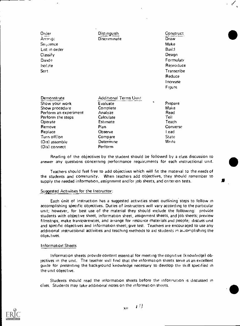
OrderArr.ig,:Ser,uenceList in orderClassifyDivideIso!ateSort
DemonstrateShow your workShow procedufePerform an experimentPerform the stepsOperateRemoveReplaceTurn off/on(Dis) assemble(Dis) connect
Distin9uishDiscriminate
Additional Terms UsedEvaluateCompleteAnalyzeCalculateEstimatePlanObserveCompareDeterminePerform
ConstructDrawMakeBuildDesignFormulatrReproduceTranscribeReduceIncrease
Figure
PrepareMakeReadTeilTeachConverseI .ead
StateWrite
Reading of the objectives by the student should be followed by a class discussion toanswer any questions concerning performance requirsaments for each instructional unit.
Teachers should feel free to add objectivEs which will fit the material to the needs ofthe students and comrnunity. When teachers add objectives, they should remember tosupply the needed information, assignment and/or job sheets, and criterion tests.
Suggested Activities for the Instructor:
Each imit of instruction has a suggested activities sheet outlining steps to follow inaccomplishing sPecific objectives. Duties of instructors will vary according to the particularunit; however, for best use of the material they should include the following: providestudents with objective sheet, information sheet, assignment sheets, and job sheets; previewfilmstrips, make transparencies, and arrange for resource materials and people; discuss unitand specific objectives and information sheet; give test. Teachers are encouraged to use anyadditional instructibnal activities and teaching methods to aid students in acornplishing theobjek.tives.
Information Sheets
Information sheets provide content essential for meeting the cognitive (knowledge) ob-jectives in the unit. The teacher will find that the information sheets serve as an excellentguide for presenting the background knowledge necessary to develop the skill specified inthe unit objective.
Students should read the information sheets before the information is discussed inclass. Students may take additional notes on the information sheets.
XII 1 . ;
I
e
o

..
Transparency Masters
Transparency masters provide inforr iation in a special way. The students may see aswell as hear the material being presented, thus reinforcing the learning process Transparencies may present new information or they may reinforce information presented in the information sheets. They are particularly effective when identification is necessary
Transparencies should be made and placed in the notebook where they will be imme-diately available for use. Transparencies direct the class's attention to the topic of discus-sion They should be left on the screen only when topics shown are under discussion.
Job Sheets
Job sheets aie an important segment of each unit The instructor should be able toarld in most situations should demonstrate the skills outlined in the job sheets Proceduresoutlined in the job sheets give direction to the skill being taught and allow both student andteacher to check student progress toward the accomplishment of the skill Job sheetsprovide a teddy outline for students to follow if they have missed a demonstration. Jobsheets also furnish potential employers with a picture of the skills being taught and theperformances which might reasonably he expected from a person who has had this training.
Assignment Sheets
Assignment sheets give direction to study and furnish practice for paper and pencilactivities to develop the knowledges which are necessary prerequisites to skill developmentThese may be given to the student for completion in class or used for homework assign-
ments. Answer sheets are provided which may be used by the student and 'or teacher forchecking student progress
Test and Evaluation
Paper pencil and performance tests have been constructed to measure student achieve
merit of each objective listed in the unit of instruction fridivalual test items may he pulledout and used as a short test to determine student achievement of d particular olgective This
kind of testing may be used as a daily quiz and will help the teacher spot dif ficul ties being
encountered by students in their efforts to accomplish the unit objective Test items for ohjectives added by the teacher should be constructed and added to the test
Test Answers
Test answers d re provided for each unit These may be used by the teacher and/orstudent for checking student achievement of the objectives
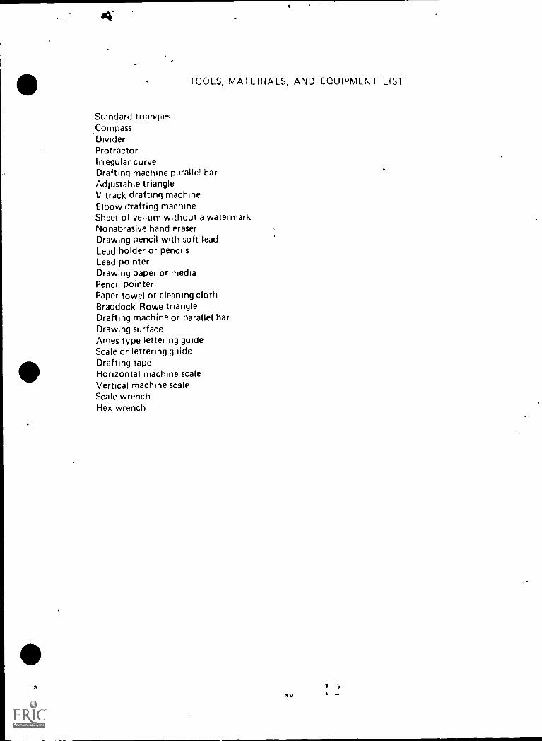
TOOLS, MATERIALS, AND EQUIPMENT LIST
Standard triangles,CompassDividerProtractorIrregular curveDrafting machine parallel barAdjustable triangleV track drafting machineElbow drafting machineSheet of vellum without a watermarkNonabrasive hand eraserDrawing pencil with soft leadLead holder or pencilsLead pointerDrawing paper or mediaPencil pointerPaper towel or cleaning clothBraddock Rowe triangleDrafting machine or parallel barDrawing surfaceAmes type lettering guideScale or lettering guideDrafting tapeHorizontal machine scaleVertical machine scaleScale wrenchHex wrench

RFFERENCES
A. A Look dt Service Safety Tecumseh, Michigan, Tecumseh Products Co.
B. The ABC's of Fire Protection. Belleville, New Jersey Kidde Portable Extinguishers/Walter Kidde and Co., Inc.
C. An 4ccident Prevention Program for School Shops and Laboratories. Washington, D.C.Office of Education/U.S. Department of Health, Education, and Welfare.
D. Allen. Cliff "About Getting a Job" and "After High School-What?" Practical FamilyLife. Greenfield, MA: Charming L. Bette, Inc., 1S77.
E. American National Standards Institute. Line Conventions an(1 Lettering New York-The American Society of Mechanical Engineers, 1979.
F The American Society of Mechanical Engineers. Line Co»ventions and Lettering.New York, NY, 10017, 1979.
G. BlAckledge, Ethel H.; Blackledge, Walter L.; and Helen .1. Kelly. You and Your Job.DaHas: South-Western Publishing Company, 1967.
H. Brown, Walter C. Drafting for Industry. South Holland, IL Goodheart-WillcoxCompany, Inc., 1974.
I. Can I Get the Job? Detroit. General Motors Put)lic Relations Staff, 1972.
J. Drawing Sheet Size and Format. New York, NY 10017 The American Society ofMechanical Elgineers, 1975.
K. Dygdon, John Thomas and Henry Cecil Spencer. Basic 7echricl; Drawing. New York1GC22 Macmillan Publishing Co., Inc., 1968
L. French, Thomas E. and Carl L. Svenson, Mechdnical Drawing. Dallas, Texas WebsterDivision, McGraw-Hill Company, 1966.
M. Federal Register Vol. 36 Number 105. Part II Department of Labor, May 29, 1971.
N. Feingold, S. Norman, and Swerdloff, Sol. Occupation.- d,;;1 Careers St. Louis: McGraw-,.
Hili Book Company/Webster Division, 1969
0. Gerevas, Lawrence E. Drafting Technology Problems Indianapohs, IN, lioward W.Sams and Co., Inc., 1976.
P. Giesecke, Mitchell, Spencer, and Hill Technica/ Drawing New York The MacmillanCompany, 1980
a Interviewing Women Candidates Washington, DC US Civil Service Commission,1974.
R. Jensen, Cecil and Helsel, Jay Engineering Drawing and Design New York Gregg
Division/McGraw.Hill Book Company, 1979

S Keeton, Marsha. Job Application and Interview. University of Kentucky: VocationalEducation Curriculum Development Center of Kentucky, 1973.
T. Kimbrell, Grady, and Vineyard, Ben S. Succeeding in the World of Work. Blooming.ton, IL: McKnight Publishing Company, 1975.
U. Milburn, Paul M. How to Get a Job. Shawnee, OK: Gordon Cooper Area VocationalTechnical School, 1957.
V. Moynihan, Moynihan, and Daeger, You and Your Job--How to Get It. Chicago: J.GFerguson Publishing Company, 1968.
W Olivo, Thomas C. and Albert V. Payne. Basic Blueprint Reading NO Sketching.Albany, New York: Delmar Publishers, Inc., 1974.
X Robert F. Noll, "Safety in the Drafting Room; Safety Education Data Sheet #95,"Chicago, IL 60611: National Safety Council.
Y Safety Practices and Procedures in School Shops. Division of Vocational Education/New Jersey Department of Education.
Z. Spence, William P. and Atkins, Michael B., Technical Drafting Metric Design andCommunication. Peoria, I L 61615: Chas. A. Bennett Co., Inc., 1980.
AA Spence, William P. Drafting Technology and Practice. Peoria, IL 61615: Chas.Bennett Company, Inc., 1973.
BB Vocational Curriculum Development and Research Center. Basic Drafting. Natch-itoches, Louisiana 71457: State of Louisiana Vocational Curriculum Development andResearch Ceipter, revised 1979.
CC. Wood, Merle W., and McKeena, Margaret The Receptionist. Dallas. McGraw-Hill BookCompany/Gregg Qivision, 1966.
DD Wright, Lawrence S. Drafting Technical Communication. Bloomington, Illinois:McKnight and McKnight Publishing Company, 1968.
EE. Your Attitude Is Showing Austin, TX. Instructional Materials, D.vision of Extension/University of Texas, 1972.
XVIII

e
...
BASIC DRAFTING: BOOK ONE
INSTRUCTIONAL/TASK ANALYSIS
JOB TRAINING: What the RELATED INFORMATION. WhatWorker Should Be Able to Do the Worker Should Know
(Psychomotor) (Cognitive)
SECTION A--UNIT I: INTRODUCTION TO DRAFTING
1. Terms
2. Areas of specialization
3. Job descriptions
4. Advantages and disadvantages
5 Minimum qualifications
6. Important personel traits
7. Abbreviations
8. Develop an organizational chart
UNIT II: GENERAL SAFETY
1. Terms
2. Safety responsibilitif3s
3. Safety hazards
10. Subscnbe to s'udent safety pledge
xix
4. Maintaining a clean andorderly snop
5. Personal safety
6. Electr;cal accidents
7. Electi ical tools
8. Fire triangle
9. Accidents
a , J

JOB AiNING Vidhat theWorker Should Bo Able to Do
(Pvclwmotorl
RELATED INFORMATION VI' letthe Worker Should Know
(Cognitive)
UNIT III BASIC TOOLS AND LINES
1. Terms
2. Standard triangles
3. Compasses
4 Dividers
5 Curves
6. Templates
7. Maintenance and care
Pencils
9 Types of lines
10 Widths of linework
11 Lead, plastic lead and ink
12 Draw lines on a drawing
13 Sharpen a compass lead
14 Divide d circle into 24 parts
15 Use i compass to draw circles and arcs
16. Use a divider
17 Me,,sure angles with a protractor
18 Use an irregular curve to construct a curvedline
UNIT IV MAJOR EQUIPMENT
1 Terms
2 PardHei bar
3 Adjustable triangle
4 Elbow drafting machine
5 V track drafting machine
6 Maintenance and care
7 Electric erasing machine
XX 1a 1 ;

JOB TRAINING. What the RELATED INFORMATION. WhatWorker Should Be Able to Do the Worker Should Know
(Pshchomotor) (Cognitive)
8 Operate a parallel bar
9. Opt ! an adjustable triangle
10. Mea ... 2 angles
11 Make adjuments to a V track draftingmachine
.2 Make adjustments to an elbow draftingmachine
*0
UNIT V APPLYING FOR A JOB
1 Terms
2 Locating job openings
3 Personal interviews
4. Methods
5 Items needed
6 Write a resume
7 Write a Ir...tter of application
8 Complete an employment application form
9 Prepare a personal portfolio
10 Practice interview questions
11 Make an appointment by phone
12 Write a follow up letter
13. Evaluate a job offer
14 Comi.are job opportunities
1 '..XXI A I
JOB TRAINING: What the RE LATED INFORMATION WhatWorker Should Be Able to Do the Worker Should Know
(Psychomotor) (Cognitive)
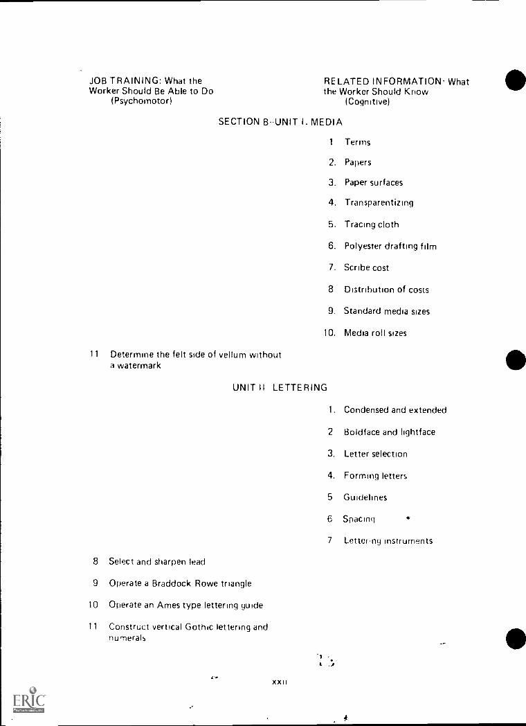
SECTION B--UNIT I. MEDIA
1 Terms
2. Papers
3. Paper surfaces
4. Transparentizing
5. Tracing cloth
6. Polyester drafting film
7. Scribe cost
8 Distribution of costs
9. Standard media sizes
10. Media roll sizes
11 Determine the felt side of vellum withouta watermark
UNIT II LETTERING
1. Condensed and extended
2 Boldface and lightface
3. Letter selection
4. Forming letters
5 Guidelines
6 Spacing
7 Lettering instruments
8 Select and sharpen lead
9 Operate a Braddock Rowe triangle
10 Operate an Ames type lettering guide
11 Construct vertical Gothic lettering andnumerals
4 .;Co
JOB TRAINING: What the RELATED INFORMATION WhatWorker Should Be Able to Do the Worker Should Know
(Psychomotor) (Cognitive)
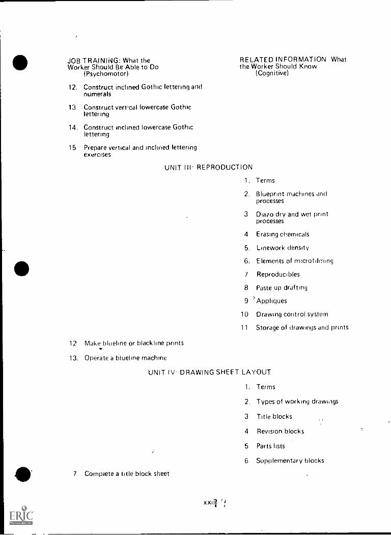
12. Construct inclined Gothic lettering andnumerals
13 Construct vert.cal lowercase Gothiclettering
14. Construct inclined lowercase Gothiclettering
15 Prepare vertical and inclined letteringexercises
UNIT III- REPRODUCTION
1. Terms
2. Blueprint machines andprocesses
3 Diazo dry and wet printprocesses
4 Erasing chemicals
5. Linework density
6. Elements of rrncrofilming
7 Reproducibles
8 Paste up drafting
9 7Appliques
10 Drawing control system
11 Storage of drawings and prints
12 Make blueline or blackline prints
13. Operate a blueline machine
UNIT IV DRAWING SHEET LAYOUT
1. Terms
2. Types of working drawings
3 Title blocks
4 Revision blocks
5 Parts lists
6 Supplementary blocks
7 Complete a title block sheet
xxiii '.!

JOB TP -\NG What the .1ELATED INFORMATION: WhatWorker Shr ild Be Able to Do the Worker Should Know
(rs,yr nrimotor) (Cognitive)
UNIT V: ARCHITECT'S SCALE USAGE
1. Terms
2 Architect's scale
3. Shapes of scales
4. Scale ratios
5 Interpret 1/16 and 1/32 graduationson a full size scale
6 Read architect's scale at full scale ratio12" = 1I-011
/ Read architect's scale at scale ratio6" = 11-0"
8 Redd arctutect's scale at scale ratio3" = 11 0"
9 Redd architect's scale at scale ratio1 1/2 1' 0"
10 Measure lines
UNIT VI: CIVIL ENGINEER'S SCALE USAGE
1. Terms
2. Cn. I engineer's scale
3 Shapes of scales
4. Scale graduations
5 Read scale using l'' = 1'-0"
6. Read scale using 1" = 20'
7 Read scdle usinl 1" = 30'
8. Read scale using 1" = 40'
9 Redd scale using 1" = 50'
10. Read scale using 1" = 60'
11 Measure lines

JOB TRAINING: What the RELATED INFORMATION: WhatWorker Should Be Able to Do the Worker Should Know
(Psychomotor) (Cognitive)
UNIT VH: MECHANICAL ENGINEER'S SCALE USAGE
1 Terms
2 Mechanical engineer's scale
3 Shapes of scales
4. Scale ratios ,
5 Read scale using ratio of 1" = ln
6. Read scale using ratio of 1/2" = 1"
7 Read scale using ration of 1/4" = 1"
8 Read scale using ratio of 1/8" 1 1"
9 Measure lines
UNIT VIII METRIC SCALE USAGE
1. Terms
2. Metric scale
3. Rules for usage
4. Scale graduations
5 Read scale at ratio of 1 1
6 Read scale at ratio of 1 2
7. Read scale at ratio of 1:5
8. Read srale at ratio of 1:25
9 Read scale at ratio of 1:33 1/3
10. Read scale at ratio of 1:75
11. Measure lines-
r

D I 1-A
INTRODUCTION TO DRAFTINGUNIT I
UNIT OBJECTIVE
After completion of this unit, the student should be able to define drafting, select areas ofspecialization within the drafting profession, and name areas in which a drafter and a drawingwill be evaluated. The student should also be able tp develop an organizational chart for-atypical engineering department. This knowledge will be evidenced by correctly performingthe procedures outlined in the assignment sheet and by scoring 85 percent on the unit test.
SPECIF IC OBJECTIVES
After completion of this unit, the student should be able to:
1. Match terms related to drafting with their correct definitions.
2. Write a definition of drafting.
3. Select areas of specialization in the drafting profession.
4. List industries that employ drafters.
1111 5. Name related ocupational fields that employ drafters.
6. Match job descriptions with their correct job titles.
7. Arrange in order the sequence for the completion of drafting work.
8. Match job classifications within a manufacturing structure with their cor-rect definitions.
9. Distinguish between the advantages and disadvantages of a drafting occupa-tion.
10. Select minimum qualifications for a drafter trainee, drafter, designer, li-censed engineer, and licensed architect.
11. Select personal traits that are important for a successful drafter.
12. Select five related skills important for a successful drafter.,.
13 Name areas in which a drafter will be evaluated.
14. Name areas in which a drawing will always be evaluated.
15. Define the abbreviations of professional drafting organizations.
16. Name advantages enjoyed by drafters who join a professional organization.
17. Cevelop an organizational chart for a typical engineering department.
D I 3-A
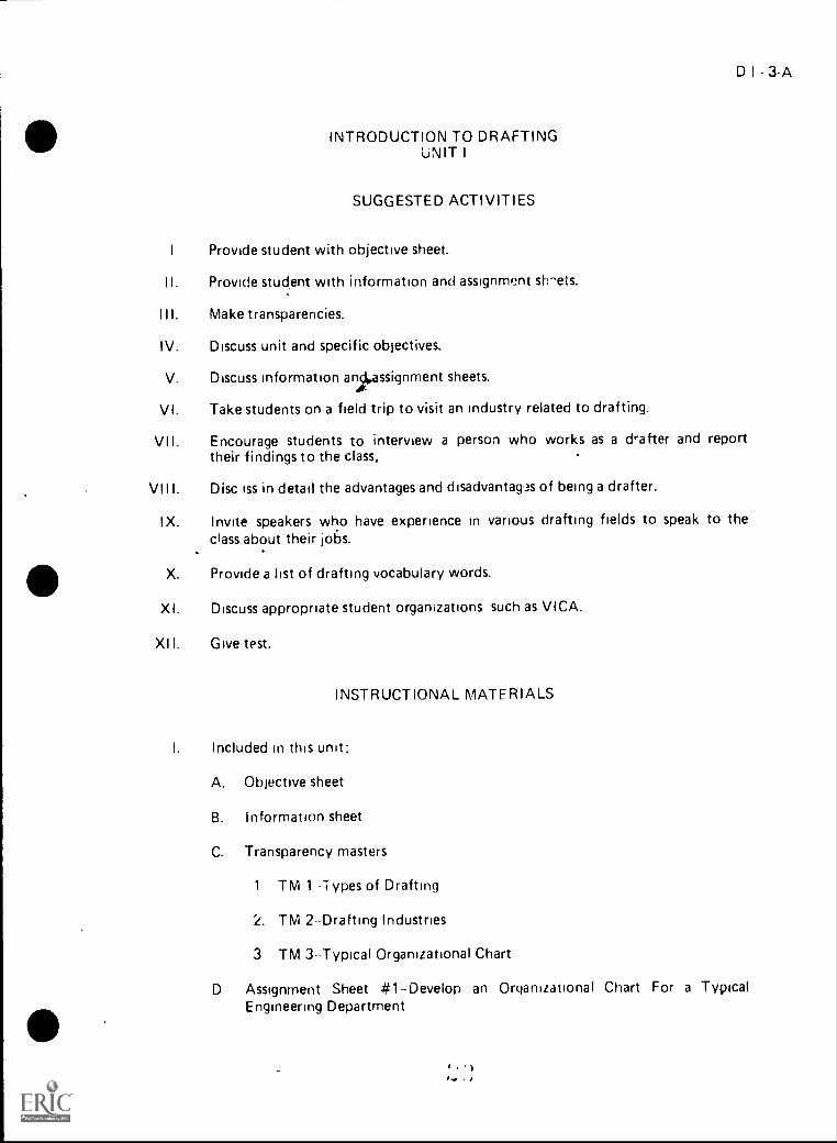
INTRODUCTION TO DRAFTINGUNIT I
SUGGESTED ACTIVITIES
I Provide student with objective sheet.
II. Provide stud,ent with information and assignment shi^ets.
I I I. Make transparencies.
IV. Discuss unit and specific objectives.
V. Discuss information andossignment sheets.A
VI. Take students on a field trip to visit an industry related to drafting.
VII. Encourage students to interview a person who works as a &after and reporttheir findings to the class.
VII I. Disc iss in detail the advantages and disadvantagas of being a drafter.
IX. Invite speakers who have experience in various drafting fields to speak to theclass about their jo6s.
X. Provide a list of drafting vocabulary words.
Xl. Discuss appropriate student organizations such as VICA.
Xl I. Give test.
INSTRUCTIONAL MATERIALS
I. Included m this unit:
A. Objective sheet
B. Information sheet
C. Transparency masters
1 TM 1 1 ypes of Drafting
2. TM 2- Drafting Industries
3 TM 3--Typical Organizational Chart
D Assignment Sheet #1-Develop an Organizational Chart For a TypicalEngineering Department
( . )I.... , )
A-A
eE. Answers to assignment sheet
F. Test
G. Answers to test iII. References:
A. Brown, Walter C. Drafting for Industry. South Holland, I L: Goodheart.Willcox Company, Inc., 1974.
B. Dygdon, John Thomas and Henry Cecil Spencer. Basic TechnicalDrawing. New York 10022: Macmillan Publishing Co., Inc., 1968.
C. Giesecke, Frederick E., et al. Technical Drawing. New York, 10022:Macmillan Publishing Company, Inc., 1980._
D. Jensen, Cecil and Helsel, Jay. Engineering Drawing incr 10esign. NewYork,: Gregg Division/McGraw-Hill Book Company, 1979.
E. Spence, William P. Drafting. Techpology and Practice. Peoria, It 61614.Chas. A. Bennett Company, Inc., 1973.
INTRODUCTION TO DRAFTINGUNIT I
A
I. Terms and definitions
INFORMATION SHEET
;
D I - 5-A
4
A. Technical-Having to do with the practical, industrial, or mechanicalarts or the applied sciences
B. Technician-A specialist in the technical details of a particular subject
C. Engineering--The application of science and mathematics in makingstructures, machines, products, systems, and processes useful to human-
ity
D. Craftsworker--A skilled worker who practices a trade; a specialist in
an area of construction or manufacturing
E. Cartography-The art of map making
F. Estimating--Cataloging and pricing all materials needed to build a
product
II. Definition of drafting--The process of taking the ideas, sketches and specificationsof designers and engineers and preparing drawings to scale, using standard symbolsand approved drafting techniques so that a product can be made
III. Areas of specialization in the drafting profession (Transparency 1)
A. Machine
B. Structural
C. Piping
D. Electrical
E. Aircraft
F. Architectural
G. Pressure vessel
H. Electronic
I. Civil
J. Computer graphics
K. Sheet metal
e , ....,... 1

6.A
INFORMATION SHEET
IV, Indüsti les that employ drafters (Transparency 2)
A. Transportation industries
B. Oil industries
C. Construction industries
D Topographic industries
E. Communications industries
F. Pipeline industries
0. Material fabrication industries
Electrical industries
I. Military related industries
V Related occupational fields that employ drafters
A Estimating-Cost analysis
B. Inspection-Ouahty control
C. Model fabrication
D Surveying .-E. Engineering aid
F. Sales Dratting.equibment and reproduction
G Technical illustration
H Cartography
VI. Job descriptions and job titles
A Trair..e
' or copies draNvinqs mdde ty, whets
2. 14, v.ses draviin.le workingrfrom insuuctions
3. Rejai s or rttravic (Jan lagcd dtawirojs
B Jjt vir dr;i'ter
1 ( ,,hd s
- 2. Vd snake simple cletail and d5SCti`tik/ drawings
Ii
0
4
C. Drafter
.
Cr 1 . 7-A
-
INFORMATION SHEETMk
\\. \
\1. Draws detail and assembly drawings
2. Works with reference material
3. Makes routine calculations
4. Takes field rates-,
D. Senior drafter-
1. Kindles design drafting detail assignments
2. Exercises considerable judgment in layout
3. Makes or reviews many calculations
E. Ch*cker
\ r
\
*
1. Checks all final drawings for errors
2. Is directly responsible for errors
3. Routes' drawings through the department \
F. Junior designer
1. Works-front engineering notes and specifications
2. Does calculations
3. Has some supervisory dutiei
-
1
1)4. Handles cbmblete design assignment with minimum supervisi n
G. Senior designerso
1. Works ivith engineering staffi
2. Works wjth mathematics, strength of materials, gear katios, anddrive systems
3. Generally, will have i college degree in engineering .br drafting,
technology , 1
4. May coordinate production deadlines, cost analysis, atid generallymanage the drafting department
;
i
1 .,*.
ita.. $
. I
*

8Aa
INFORMATION SHEET
H. Chief Drafter
1. Responsible for all drafting in a company0
A 2. In charge of hiring and firing
3. Sets work sChedules, company drafting standards, and work loads
4. Responsible for budgeting and purchasing for the needs of drafting department
VII. Sequence for the completion of drafting work
A. Preliminary design layout and rough sketches
B. Set of working drawings with materials list and specifications
C. Check9
D. Corrections
E. Engineer's approvala
F. Drawing release
G. Prints made and sent to fabricators
H. Revisions (when necessary)
VIII. Job classifications within a manufacturing structure
A. Engineers--Design, management
B. Technicians-Development, drafting
C. Craftworkers--iyoduction, skilled trades
C.'
/IX. Advantages and disadvantages of a drafting occupation
*
A. Advantages
1. Clean indoor working conditions
2. Open job market
't 3. Lots of overtime available
4. Sense of self-satisfaction and pride
5. Stepping stone for higher paying occupations
6. Variety of challenging assignments
..

*,e
INFORMATION SHEET
D I - 9A
B. Disadvantages
1. Confinement to one area
2. Long hours at times of peak production
3. Responsible to both management and production
4. Rigid accountability for accuracy of work
5. Knowledge of many technical fields required
6. Very little physical exercise
7. Rigid time limits for doing work
X. Minimum qualifications for a drafter trainee, drafter, designer, licensed engineer,licensed architect
A. Drafter trainee
1. High school diploma, or be successfully working toward one
2. Course work in vocational drafting with average or better grades
3. One year of algebra and one year of geometry
4. Good character references
5. Good school attendance record
B. Drafter
1. High school diploma
2. Two or more years of vocational drafting with average or bettergrades
3. One year of algebra and one yegi- of geometry
4. Good character references
5. Successful completion of an in-company training period- _,..../
(NOTE: In some companies this could be as long as one year astrainee.)
C. Designer
1. Associate degree in technical area
2. Minimum five years drafting experience III a specialty area
3. Good work credentials

10 A
4
r,FOPMATInN SHEET
D. Licensed , Nine, r
1 Degree in enginr ing (fivo years college)
2. Successtu; completion -if st;ih. examination for engineewig
3. Succr-.sful completion of ant)! -nticeslup under licensed enginec,
E. Architect
1. Degree in architectural area (six years college)
2 Successful completion of three year apprenticeship under licensedarchitect
3. Successful completion of state examination
(NOTE:. These ii,inimur, requirement, may vary for various statesand for J aHons drat I ri occupations but can be considered as ageneral description.)
Xl. Personal nails that are unpor (ant for a sucressful drafter
A Listens to and foiloc.s ;mstiuction,, vi
B Punctu
Dependarle and
D. An;e to accent cow,' uctive c!itRisn,
E Success oriented willin,:ness In ontinue educ,.tion
F. Af,ility u ,it (1,110k, and wor t. pato fl1 a, detailed work for longhour,.
(1 .11 iole to vvol ' 4- I other'
XII Related !moor, . LI' ,!. ! (i;m1
A Sp.-!ed
13 f)pe: Ii .ii.i I. nue
C. tf. /
E L t, .
Mat .
S.

D I - 11-A
INFORMATION SHEET
G. Ability to visualize three-dimensional objects recorded on a two dimen-sional plane .
H. Ability to do neat legible lettering
I. Ability to use alphabet of lines
XIII. Areas in which a dratter will be evaluated
A. Speed
B. Accuracy
C. Completeness
D. Ability to get along with others
E. Ability to work unsupervised
F. Wasted materials and man hours
X1 V. Areas in which a drawing will always be evaluated
A. Accuracy
B. Linework
C. Lettering
D. Neatness
E. Dimensioning
F. Reproducibility
XV. Abbreviations of professional drafting organizations and their meanings
A. AIDD--American Institute of Design Draftsmen
B. SME--Society of Mechanical Engineers
C. SPE--Society of Professional Engineers
D. AIA-Arnerican Institute of Architects
E. NHBA--National Home Builder's Association (local association)
ASHRAE--American Society of Heating, Refrigerating and Air-Conditioning Engineers

12-A
INFORMATION SHEET
.XVI. Advantages enjoyed by drafters.who join a professional organization
A. Helps them keep up with new trends within a specialty area
B. Allows them to maintain contacts within the industry for job openingsand business trends
C. Potential library of reference materials
(NOTE: Some organizations publish standards and reference materialsfor their trade area.) .
e
D. Certification credentials offered by many professional organizationi
(NOTE; Many of these credentials are recognized nationally. These canbe extremely important if a person wants to change localities withinthe United States.)
I

:1.
TYPES OF DRAFTING
1 . Machine2 . Structural3 . Piping4 . Electrical
5 . Aircraft6 . Architectural7 . Pressure Vessel
8 . Electronic
9 . Civil1 0 . Computer Graphics1 1 . Sheet Metal
r
It I)CI .1
Am.
D I - 11A
TM 1
II.

DRAFTING INDUSTRIES
1. Transportation Industries
2. Oil Industries
3 . Construction Industries
4. Topographic Industries
5. Communications Industries
6. Pipeline Indusiries
47 . Material Fabrication Industries
8 Electrical Industries
9. Military Related Indukries
I - 15-A
TM 2

a
w
,
I
r
Typical Organization Chart
Chief Drafter
e
Senior Designer(Engineering) Checker
Senior Drafter(Drafting)
Design TechnicalIllustrations
Jig andFixtures
Details
s
Reproduction
roductiooordinato
Trainee
Squad Leader(Junior Designer)
Welding MachineShop
JuniorDrafter #1
Drafter#1
Drafter#2
Drafter#3
Sh tMetal
Squad Leader(Drafter)
JuniorDrafter #2
JuniorDrafter #3
n f1-.0 ')

s
D I - 19A
INTRODUCTION TO DRAFTINGUNIT I
,
ASSIGNMENT SHEET *1-DEVELOP AN ORGANIZATION CHARTFOR A TYPICAL ENGINEERING DEPARTMENT
Procedure:
1. Determine the areas of responsibility within the given department
2. Determine the job titles for the various individuals within the department
3. Prepare a block diagram sketch of the various supervisor's in the department
Example:
DEPT. HEAD -
4
SENIOR ENGINEER
LCHECKER
LSENIOR DRAFTER
(NOTE: All individuals with similar responsibilities will be shown in a straight line
across the chart.)
J.,

20-A
ASSIGNMENT SHEET *1
4. Continue down the chain of command on the sketch until it includes every job titlwithin the department
Example:
DEPT. HEAD
SENIOR DRAFTER
DRAFTER
JUNIORDRAFTER
TRAINEE
CHECKER SENIOR ENGINEER
JUNIOR JUNIORDESIGNER I DESIGNER
(NOTE: Normally, squares are use to represent positions within a department, andcircles to represent positions or components not in the department.)
5. Complete the sketch with all flow lines between blocks.
INOTE: Charts are not to scale but care must be taken to keep all squares in pro-portion and to a;low enough room for lettering within the square.)

D - 21-A
ASSIGNMENT SHEET *1
Problem:
Develop a sketch of an organizational chart showing the flow of authority for a typicalengineering department. Refer to mnquww_t_ney. 3. Get your sketch approved by yourinstructor. Use the following infon.17.77'''"'Y
Name of Corporation: Utility international
Personnel:
1. One Chief Drafter -14
2. Two Senior drafters, one in charge of drifting, one in charge of engineering
3. One Checker, who reports directly to chief drafter and is equal to senior drafters
4. Two squads of three junior drafters, one squad is in engineering
5. Two drafters who serve se squad leaders, one in engineering, one in drafting
6. Two trainees, one in engineering, one in drafting, who report directly to squad
loaders
I.1)l

ISENIOR DRAFTER 1
INTRODUCTION TO DRAFTINGUNIT I
ANSWERS TO ASSIGNMENT SHEET *1
*ORGANIZATION CHART
CHIEF DRAFTER
DRA TER'I&
TRAINEE I
CHECKER
TRAINEE
UTILITY INTERNATIONAL CORI.ENGINEERING DEPT
SENIOR DRAFTER I
(
DRAFTER
JUNIORDRAFTER
JUNIORDRAFTER
s
I - 23-A

0
INTRODUCTION TO DRAFTINGUNIT I
NAME
TEST
1. Match the terms on the right with their correct definitions.
a. Cataloging and pricing all materiels needed tobuild a product
b. The application f science and mathematics inmaking structu , machines, products, sys-tem., and useful to humadity
c. A skilled worker who practices a trade;a specialist in an area of construction ormanufacturing
d. Haying to do with the practical, industrial, or,-mechanical arts or the applied sciences
e. The art of map making.-,1
f. A specialist in the iechnical details of a parti-
I\cu subject
2. Define drafti
D I 25-A
1. Technical
2. Engineering
3. Technician
4. Craftsworker
5- cartoliraPhy
6. Estimating
3. Seleet areas of specialization in the dieting profession by placing an "X" ln theappropriate blanks.
A PipIng
b. Aircraft
c. Political science
d. pectronic
e. Architectural
f. Sheet metal

28-A
4. List six industries that employ drafteis.
a. d.
b. e.
C. f.
S. Name five related occupational fields that employ drafters.
a.
b.
C.
d.
C.
6. Match the job titles on the right with their correct descriptions.
a. Traces or copies drawings made by others;revises drawings, working from instruc-tions and repairs or redraws damaged draw-ings.
b Checks all final drawings for errors, is directlyresponsible for errors and routes drawingsthrough the department
c. Handles design drafting detail assignments,exercises considerable judgment in layout andmakes or reviews many calculations.
d Works with engineering staff; works withmathematics, strength of materials, gear
ratios, and drive systems; generally, will havea college degree in engineering or draftingtechnology, and may coordinate productiondeadlines, cost analysis, and generally managethe drafting department
e. Works from engineering notes and speci-fications, does calculations, has some super-visory duties, and handles complete designassignment with minimum supervision
f Responsible for all drafting in a company; incharge of hiring and firing; sets work sched-ules, company drafting standards, and workloads, and responsible for budgeting andriLitchastng for the needs of drafting department
1. Trainee
2. Junior drafter
3. Senior drafter
4. Checker
5. Junior designer
6. Senior designer
'7. Chief drafter
8. Drafter

g. Cor,ects and revises drawings and may makesimple detail and assembly drawings
h. Draws detail and assembly drawings, workswith reference material, makes routinecalculations and takes field notes.
0 I 27-A
7. Arrange in order the sequence for the completion of drafting work by placing thecorrect sequence number in the appropriate blank.
a. Revisions
b. Check
c. Preliminary design layout and rough skAtches
d. Prints made and sent to fabricators
e. Corrections
f. Engineer's approval
g. Drawing release
h. Set of working drawings with materials list and specifications
8. Match job classifications within a manufacturing structure with. their correct defini-tions.
a. Design, management 1. Technicians
b. Production, skilled trades 2. Engineers
c. Dgvelopment, drafting 3. Craftworkers
9. Distinguish between advantages and disadvantages of a drafting occupation by placingan "X by each statement that is an advantage.
a. Clean indoor working conditions
b. Open job market
c. Confinement to one area
d. Long hours at times of peak production
e. Respons;bilc to both management and production
f. Variety of challenging assignments
q. Stepping stone for higher paying occupations
h. Rigid accountability for accuracy of work
i. Knowledge of many technical fields required

28-A
i Lots of over time available
k. Very little physical exercise
I. Sense of self satisfaction and pride_10. Select minimuni qualif ications for a drafter trainee, drafter, designer, licensed engineer,
and iicensed architect by matching their qualifications with the job title on the right.
a. 1) High school diploma , or be successfully working toward one
1. Designer
2) Course work in vocational driftingwith average or hetter grades
2. Architect
3) One- year of algebra and one yeai ofgeometry
3. Crafter trainee
4) Good character references 4. Drafter.. 5) Good school attendance record
5. Licensed engineerb. 1) High school diplomd
2) Two or more years of vocational drafting3) Succelsful completion of an in-company
it aining period
c 1) Associate degree in technical area2) Minimum five years drafting experi-
ence .ri a specialty area3) Good work credentials
d 1) Degree in engineering2) Successful completion of state examina-
tion for engineering specialty area31 Sacessful completion of apprenticeship
under licensed engineer
c. I I Degree in architectural area2) Successful completion of three-year
apprent,ceship under licensed architect3) Successful completion of state examina-
tion
11. Select personal traits that are important for a successful drafter by placing an '' X" inthe appropriate blanks.
a. Listens to and follows instructions well
b Ahiliti to not listen tu constructive criticism
c. Willingness to he satisfied with present education
d. Punctual
e. Must he able to work well with others
44 I

D I 29A
'
12. Select five related skills important for a successful drafter by placing an "X" in theappropriate blanks.
a. ?Speed *
. b. Operate machinery
c. Manual dexterity
d. Communication skills
e. Do survey work
f. Math skills
g. Operate drafting equipment correctly
13. Name five areas in which a drafter will be evaluated.
a.
b.
d.
e.
14. Name five areas in which a drawing will always be evaluated.
a.
b.
C.
d.
e.
15. Define the abbreviations of the professional drafting organizations listed below.
a. NHBA
b. SME
C. ASHRAE
d. AIDO
e. AIA
(
4 ......
A 4 )

30-A
16. Name three advantages njoyed by drafters who join a professional organization.
a.
b.
C.
17. Develop an organizational chart for a typical engineering department.
(NOTE: If this activity has not been accomplished prior to the test, ask your instructorwhen it should be completed.)
i
A.
1. 4 ts40
/

1. t 6b. 2C. 4d. 1
e. 5f. 3
INTRODUCTION TO DRAFTINGUNIT I
ANSWERS TO TEST
DI-31-A
2. The process of taking the ideas, sketches and specifications of designers and preparingdrawings to scale, using standard symbols and approved drattg techniques so that aproduct can be made
3. a, b, d, e, f
4. Any six of the following:
a. Transportation induslriesb. Oil industriesc. Construction industriesd. Topographic industriese. Communications industriesf. Pipeline industriesg. Material fabrication industriesh. Electrical industriesI. Military related industries
5. Any five of the following:
a. Estimating--Cost analysisb. Inspection-Quality controlc. Model fabricationd. Surveyinge. Engineering aidf. Sales--Drafting equipment and reproductiong. Technical illustrationh. Cartography
6. & 1 e. 5. b. 4 f. 7c. 3 g, 2d. 6 h. 8
7. a. 8b. 3C. 1
d. 7e. 4f. 5g. 6h. 2
44 I
6

32-A
8. a. 2
b. 3
C. 1
9. a, b, f, g, j, t
10. a. 3b. 4
C. 1
0. 5e. 2
1 1 . a, d, e
12. a, c, d, f, g
13. Any five of the following:
a. Speedb. Accuracyc. Completenessd. Ability to get along With otherse. Ability to work unsupervisedf. Wasted materials and man hours
14. Any five of the following:
a. Accuracyb. Lineworkc. Letteringd. Neatnesse. Dimensioningf. Reproducibility
15. a. National Home Builder's Associationb. Society of Mechanical Engineersc. American Society of Heating. Refrigerating
and Air-Conditioning Engineersd. American Institute of Design Draftsmene. Society of Professional Engineersf. American Institute of Architects
16. Any three of the following:
-At
a. Helps them keep up with new trends within a speciality areab. Allows them to maintain contacts within the industry for job openings and busi-
ness trendsc. Potential library of reference materialsel. certification credentials offered by many professional organizations
17. Evaluated to the satisfaction of the instructor,

UNIT II
UNIT OBJECTIVE
D I 33-A
After completion of this unit, the student should be able to list reasons and select rules formaintaining a clean and orderly drafting classroom. The student should also be able to listten .specific rules for personal safety and describe the steps to be followed in ow of anaccident This knowledge will be evidenced by correctly performing the procedures outlinedon the assignment sheet and by scoring 100 per cent on the unit test.
SPECIFIC OBJECTIVES
After completion of this unit, the student should be able to:
1. Match terms related to general safety with their correct definitions.
2. Select safety responsibilities of school, instructor, and student.
3. Distinguish between safety hazards involving classroom environment and class-room equipment.
4. List two reasons for maintaining a clean and orderly drafting classroom.
5. List six steps in maintaining a clean and orderly shop.
6. List ten specific rulestor personal safety in the drafting classroom.
7. List five potential hazards of misusing electricity.
8. List three major causes of electrical accidents.
9. List four safety rules for using electrical tools.
10. Match the classes of fires to the correct definitions.
11. Label the three components of the fire triangle.
12. Match the types of fire extinguishers with their operation and the class of firesthey are intended to extinguish.
13. List the two classes of fires that might be encountered in a typical draftingclassroom.
14. List six steps to be follovied in case of an accident in the classroom.
15. Indicate a willingness to work safely by subscribing to the student safety pledge.

0 I - 35-A
GENERAL SAFETYUNIT II
SUGGESTED ACTIVITIESis
I. Provide student with objective sheet..1
II. Provide student with information and assignment sheets.
III. Make transparencies...
IV. Discuss unit and specific objectives.
V. Discuss information and assignment sheets.
VI. Show a safety film.
VII. Invite fire department representative to give a talk on fire safety.
VIII. Discuss evacuation plan.
IX. Have a fire and disaster drill.
X. Have an accident victim address the class.
Xl. Have a paramedic/nurse visit the class and give lecture on first aid.
XII. Give test.
INSTRUCTIONAL MATERIALS
I. Included in this unit:
A. Objective sheet
B. Information sheet
C. Transparency masters
1. TM 1-- Do Not Misuse Electrical Tools /
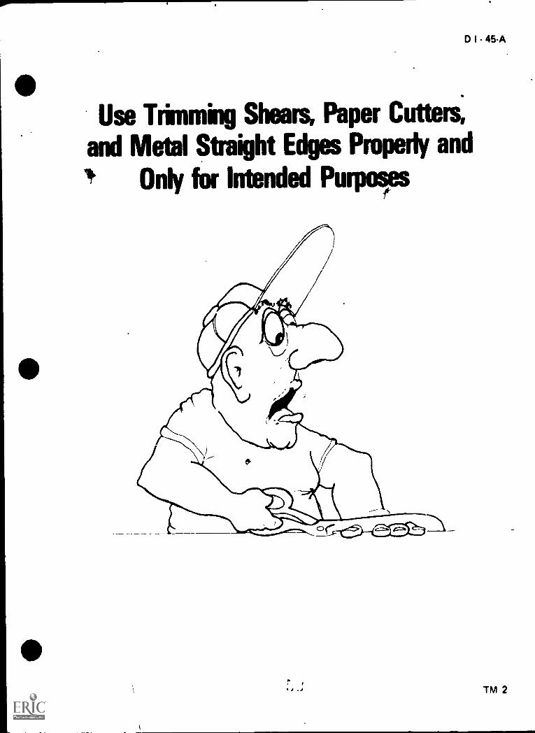
2. TM 2--Use Trimming Shears, Paper Cutters, and Metal Straight EdgesProperly and Only for Intended Purposes
2. TM 3--Handle Sharp, Pointed Instruments With Care
4. TM 4--Avoid Horseplay
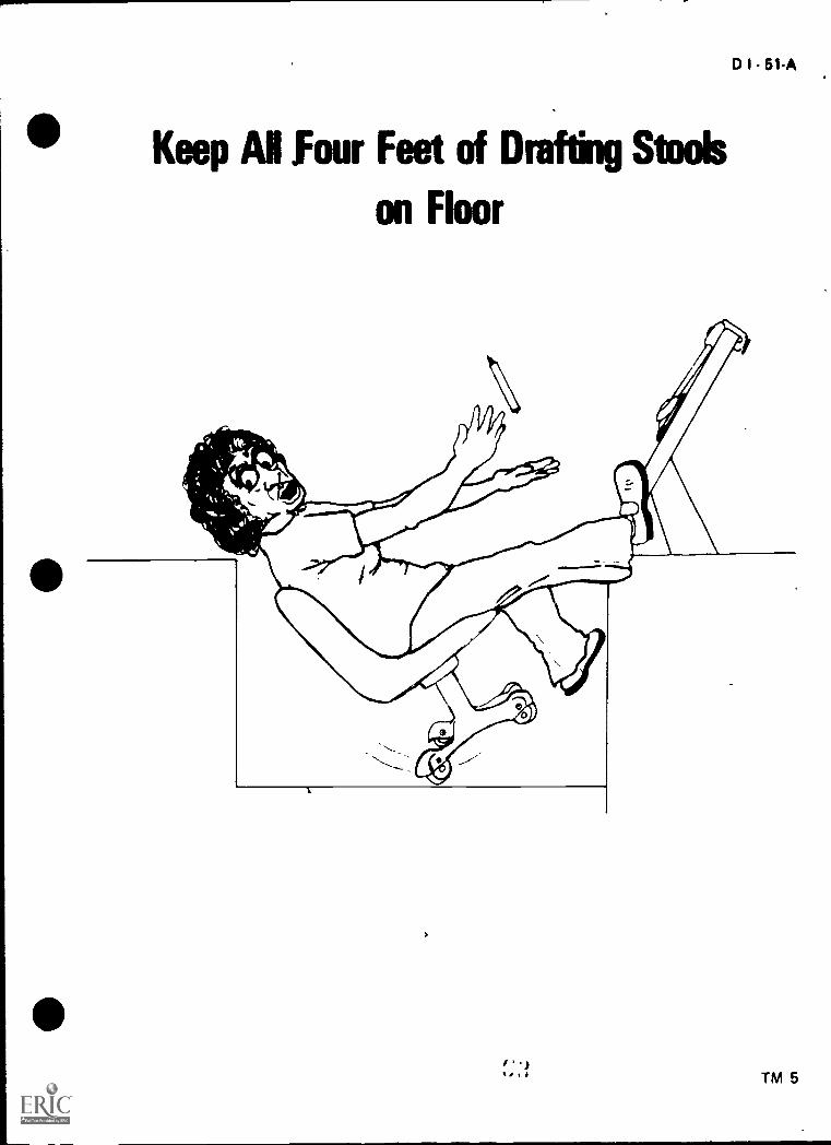
, 5. TM 5--Keep All Four Feet of Drafting Stools on Floor
6. TM 6--Use Both Hands to Raise and Lower Drafting Table Tops
)

3C-A
7. TM 7 -Use Reproduction Equipment With Proper Care
8. TM 8--Do Not Throw Any Objects
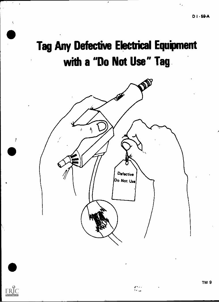
9. TM 9--Tag Any Defective Electrical Equipment With a "Do Not Use"Tag
10. TM 10--Follow All Rules and Regulations of the School Completely
11. TM 11--Potential Results of Improper Usage of Electricity
12. TM 12--The Fire Trianglec'
13. TM 13--Know Your Fire Extinguisher
D. Assignment Sheet #1--Subscribt to the Student Safety Pledge
E. Test
F Answers to test
3.
II. References:
A. The ABC's of Fire Protection. Belleville, New Jersey: Kidde Portable Extin-guisher,s/Walter Kidde and Co., Inc.
B. An Accident Prevention Program for School Shops and Laboratories. Wash-ington, D.C.: Office of Education/U.S. Department of Health, Education,and Welfare.
C. Federal Register. Vol. 36. Number 105. Part II. Department of Labor,May 29, 1971.
b. Safety Practices and Procedures in School Shops. Division of Vocation-al Education/New Jersey Department of Education.
,...,40
E. A Look at Service Safety. Tecumseh, Michigan: Tecumseh Products Co.
F Robert F. Noll, "Safety in the Drafting Room; Safety Education DataSheet #95, "Chicago, IL 60611: National Safety Council.
III. Additional materials:
A. Film- "Housekeeping Means Safekeeping." 146-009. Journal Films, 930Pinter Avenue, Evanston, IL 60202.
B. Firn- "Stop a Fire Before it Starts." 146-024, Journal Films, 909 DiverseyParkway, Chicago, IL 60614.
r; 1
s

GENERAL SAFETYUNIT II
INFORMATION SHEET
I. Terms and definitions
0 I 37-A
A. SafetyState or condition of being safe; freedom from danger, risk, or injury
B. Accident-Any suddenly occurring, unintentional vent which causes injuryor property damage I
C. First aid-Immediate, temporary care given the victim of an accident orsudden illness until the services of a physician can be obtained
D. Hazard-A potential source of danger
II. Safety responsibilities of school, instructor, and student
A. School
1. Provide adequate facilities, including a classroom large enough toaccommodate students without crowding
2. Provide modern, up-to-date equipment and working conditions
3. Provide adequate facilities for good lighting and temperature controls
B. Instructor .
1. Provide a well-organized, progressive instructional program that chal-lenges all students, thus eliminating free time when horseplay andunsafe acts commonly occur
2. Provide a well-planned cleanup program with individual assignments
(NOTE: It's a good idea to rotate cleanup duties weekly.)
3. Provide adequate instruction in the safe use and proper care of alldrafting and reproduction equipment
4. Provide plans for students to follow in emergency situations
5. Provide an accident reporting system which insures fast and efficienthelp in case of accident
,
. t.
0

384
c
,INFORMATION SHEET
C. Student
1. Be responsible for own area and equipment and see that it is keptclean and in good working condition
2. Report any safety hazard to instructor immediately
3. Do not abuse or misuse any piece of equipment in the classroom
4. Conduct oneself in a manner conducive to safe practice
III. Safety hazards involving classrooma
environment and classroom equip:rent-..
r
A. Classroom environment,.
1. Narrow aisles
2. Poor lighting
3. Crowded conditions
4. Lack of storage area
5. Poor maintenance of facility
6. Misuse of extension cords
\r\\
.1
t.
B Classroom equipment
1. Desks and drafting tables with Tharp corners and adjustable tops
2. Reproduction equipment (improper handling)
3. Electrical outlets and electrical equipment
4. Paper cutters and trimmers
V. Reasons for maintaining a clean and orderly drafting classroom
A. To provide the safest working conditions possible
B. To provide working conditions as near as possible to what will be found inindustry
(NOTE: Because many industry representatives and potential employersvisit drafting programs in session, a clean and orderly classroom is an impor-
tant public relations tool)

V ..
-,
D I - 39-A '.
INFORMATION SHEET
V. Steps in maintaining a clean and orderly shop
A. Arrange desks and drafting tables to permit safe, efficient work practices aniease of cleaning
B. Store materials and supphes in safe, secure places
C. Keep working stations clean and free of debris
D. Keep floors clean and free of obstacles
E. Have sufficient brooms, brushes, and other housekeeping equipment readilyavailable
F. Develop procedures for cleanup and follow them on a daily basis
VI. Specific rules for personal safety in the drafting classroom
A. Do not misuse electrical tools (Transparency 1)...,..
(NOTE: Report all electrical failures immediately.)
B. Use trimming shears, paper cutters and metal straight edges only for in-
tended purposes (Transparency 2)
(NOTE: Do not remove guard from paper cutter.)
C. Handle sharp, pointed instruments with care (Transparency 3)
(NOTE: Never throw a compass or a divider.)
D. Avoid horseplay (Transparency 4)
(NOTE: More accidents reiult from horseplay than any other single cause.)
E. Keep all four feet of drafting stools on the floor (Transparency 5)
(NOTE: Leaning back and tilting a drafting stool is a dangerous practice.)
F. Use both hands to raise and lower drafting table tops (Transparency 6)
(NOTE: Be prepared to hold table top as control rod knobs are loosened.)
G. Use reproduction equipment with proper care and only after instructionin its use and with the instructor's permission to use it (Transparency 7).
(NOTE: Means must be provided for eyewash equipment.)
1

40-A
INFORMATION SHEET
H. Do not throw any object (Transparency 8)
Tag any defective electrical equipment with a "Do N9t Use" tag and turn itin to instructor (Transparency 9)
J. Follow all rules and regulations of the school (Transparency 1(4'
VII. Potential hazards of misusing electricity (Transparency 11)
A. Electrical shock
B. Ruined equipment
C. Fire
p. Hospitalization
E. Death
VIII. Major causes of electrical accidents
A. Carelessness
B. Poor equipment maintenance
C. Equipment not grounded properly
IX. Safety rules for Using electrical tools
A. Use three wire, grounded equipment
(NOTE: Never cut ground prong from a plug.)
B. Use proper size electrical cord
C. Do not use frayed or damaged cords
D. Stand on dry nonconductive surfaces
X. Classes of fires
A. Class A--Fires that occur in ordinary combustible materials
Examples: Paper, wood, rags, and rubbish
B. Class B--F ires that occur with flammable liquids
Examples: Gasoline, oil, grease, paints, and thinners
,)
.1)
fr.)
INFORMATION SHEET
C. Class C-Fires that occur in or near electrical equipment
Examples: Motors, switchboards, and electrical wiring
D. Class D--Fires that occur with combustible metals
Example: Magnesium
Xl. Components of the fire triangle (Transparency 12)
A. Fuel- Any combustible material
B. Heat-Enough to raise the fuel to its ignition temperature
C Oxygen-Necessary to sustain combustion
(NOTE: To produce f re these three elements are necessary and must bepresent at the same time. If any ore of the three is missing, a fire cannot be
started With the removal' of any one of them, the fire will be extinguished.)
Xi I. Types of fire extinguishers, their method of operation, and the classes of fires
they are intended to extinguish (Transparency 13)
A. Pressurized water -Operates usually by squeezing a handle or trigqer, used on
Class A fires
B. Soda acid Operates by turning oxbrujuisher upside down, used d'n Class
A fires
C Carbon dioxide (CO- ) Ooerates usuall y by squeezing handle or trigger;used on Class B arm ;ffes
(), Dry chemical Operates lisua",.. by squo0,,,nii o handle, trigger, or levcr, used
on ads; B, C and D fires
(NOTE On Class D fires, dry sang is as effective as any dry chemical otherthan Purple X The cost of the Purple X chemical places it Out of reach of
most shops I
E. Foarn- -Operates bi turning extinguisher upside down, used on Class A
and B fires
XIII Classes of fires that might he encountered in a typical drafting classroom
A Coss A
8 Class C
42 A
INFORMATION SHEET
XIV. Steps to be followed in case of an accident in the classroom
A. All accidents and injuries will be reported to the instructor no matter howminor they may seem
B. First aid will be administered if needed
(NOTE: Check with local school policy.)
C. Student will be taken to school nurse
D. Student's parent or guardian will be notified if school nurse requires studemto see a physician
E. Investigation of the accident will take place to determine the cause of theaccident and ways to prevent the same accident from happening again
F. Accident report form will be filled out by instructor

01-41A
Do Not Misuse Electrical ToolsI
v
TM 1
D I - 45-A
Use Trimming Shears, Paper Cutters,
and Metal Straight Edges Properly and
! Only for Intended Purposes
TM 2

Handle Sharp Pointed Instruments with Care

Avoid Horseplay
I ' 1
D I - 49-A
TM 4
Keep Ai Four Feet of Drafting Stoob
on Floor
DI51A.
I'.)lIgh TM 5

D I - 53-A
Use Both Hands to Rabe and LowerDrafting T; Ile Tops
;1 1 TM 6

Use Reproduction Equipmentwith Proper Care
Incorrect
,
Correct
m0 I - 55-A
:4.
TM 7

c ,
Do Not Throw Any Objects
/
0 I - 59-A
Tag Any Defective Electrical Equipment
with a "Do Not Use" Tag
If
TM 9

Follow Al Rules ambRegulations
of the &Mel Completely
Olar
CI I - 61-A
TM 10

DI61A
Potential Results of Improper
Usage of Electricity
Never BecomePart of the Circuit
4 I /
\\A
A Never Use ElectricalTools Beyond
Their Rated Capacity
TM 11

-IK
f;11-- T 1
,
The Fire Triangle
To produce fire, three things must be present at the same time.
1010
OXYGENIf any one of the three is missing, a fire cannot, be started or, with the removal
of any one, the fire will be extinguished
OXYGEN OXYGEN0

KNOW YOUR FIRE EXTINGUISHER
TYPEEXTINGUISHER
WATER TYPE FOAM CARSONDIOXIDE
DRY CHEMICAL
flSTORED
PRESSUREWATER
TANK
..
PUMPSODA ACID
CARTRIDGEOPERATED
STOREDPRESSURECO2FOAM
CARTRIDGEOPERATED
TYPES OF FIRES
CLASS A:WOOD, PAPER, TRASHHAVING GLOWING EMBERS
YES YES YES YES YES NO NO NO
CLASS 8:FLAMMABLE LIQUIDS.GASOLINE, OIL, PAINTGREASE, ETC
NO NO NO NO YES YES YES YES
CLASS C:ELECTRICALEQUIPMENT NO NO NO NO NO YES YES YES
CLASS D:COMBUSTIBLE METALS
* * *
PUMPHANDLE
*
TURNUPSIDEDOWN
*
TURNUPSIDEDOWN
* * *
PULLPIN,
SQUEEZELEVER
RUPTURECARTRIDGE,
SQUEEZELEVER
PULLPIN,
SQUEEZELEVER
METHODOF
OPERATION
SQUEEZEHANDLE
ORTURNVALVE
TURNUPSIDEDOWNAND
BUMP
..,,. ..I
DO NOT USE FIRE EXTINGUISHER. SMOTHER FIRE WITH DRY SAND, GRAPHITE, DIRT, OR SODA ASH.
OP
'1 4II A

tD I 69-A
GENERAL SAFETYUNIT II
ASSIGNMENT SHEET #1--SUBSCRIBE TO THE STUDENT SAFETY PLEDGE
STUDENT SAFETY PLEDGE FORM FOR VOCATIONAL DRAFTING
who is
enrolled in Vocational Drafting, will as a part of his/her shop experience, operate machinesand instruments, providing that his/her parent or guardian gives written permission.
It is understood that each student will be given proper instruction, both in the use of theequipment and in the correct safety procedures concerning it, before being allowed tooperate it himself/herself. The student must assume responsibility for the following safepractices, and we therefore ask that he/she subscribe to the following safety pledge.
1. I PROMISE TO ABIDE BY ALL SAFETY RULES FOR THE SHOP AS FOLLOWS:
a. To not misuse electrical tools
b. To use trimming shears, paper cutters, and metal straight edges only for theirintended use
c. To handle sharp pointed instruments with care
d. To avoid horseplay
e. To keep all four legs of drafting stools on the floor
f. To use both hands to raise and lower drafting table tops
g. To use reproduction equipment with proper care and only after instructionin its use and with the instructor's permission to use it
h. To not throw any object
I. To tag any defective electrical equipment with a "Dq Not Use" tag and turnit in to the instructor
j. To follow all rules and regulations of the school
2. I WI LL REPORT ANY ACCIDENT TO THE TEACHER IMMEDIATELY.
DATE STUDENT'S, SIGNATURE
I hereby give consent to allow my son/daughter to operate, all machines and equipmentnecessary in carrying out the requirements of the course ih wnich he/she is enrolled.
DATE PARENT'S SIGNATURE(Required according to school
policy)
(NOTE Parents are cordially invited to visit the school,to inspect the Drafting Lab at anytime.)

GENERAL SAFETYUNIT II
NAME
TEST
1. Match the terms on the right with their correct dbfinitions.
a. Immediate, temporary care given the victimof an accident or sudden illness until theservices of a physician can be obtained
b. State or condition of being safe, freedomfrom danger, risk, or injury
Any suddenly occurring, unintentional evertwhich causes injury or proper damage
d. A potential source of danger
D I 71-A
1. Safety
2. Accident
3. First aid
4 Hazard
2. Select safety responsibilities of the school, instructor, and student by placing in theappropriate blanks an "S" to indicate school responsibilities, an "I" to indicate instruc-tor responsibilities, and an "X" to indicate student responsibilities.
a. Provide adequate facilities, including a classroom large enough to accom-modate students without crowding
b. Be responsible for own area and equipment and see th,ic it e, kept in goodworking condition
c. Conduct oneself in a manner conducive to safe practice
d Provide a well-orcanizecl, progressive, instructional program that challengesall students, thus eliminating free time when ;;orseplay and unsafe actscommonly occur
e. Provide plans for students to follow in emergency situations
f Provide adequate facilities for good lighting and temperature controls
Do not abuse or misuse any piece of equipment in the classroom
h Provide adequate instruction in the safe use and proper care of all draftingand reproduction equipment

7 2 A
Provide a well ol,.nned cieanup program with individual assignments
Rcport dny 'safety hazard to instructor immediately
k. Provide modern 1;0 to date egLipment and working conditions
provide an accident reporting systern which insures fast and efficient helpin case of accident
hoween safety hazards involving classroom emoronmfmt and classroomn-rwr!- by placIng an "X" by all tatements concerning classroom equinnwnt
a Desks and drafting taoles with sharp corners and adjustable tops
b. Poor maintenance of facility
r E lectr ical outlets and electrical equipment
d Lack of stotiige area
Pr,r)r lighting
Paper cutters and trimmers
rj Crowded conditlutiS
R eproduction egulpmeni
Naircw aisles
Inaliir reasons for 11,a Hi 11111,1q a cluan and or deny dratttnj das,,room
of.ps in waintain,nri a clean and orderly shop

6. List ten specific rules for personal safety in the draft:ng classroom.
a.
b.
C.
d.
e.
f.
9.
h.
j,
D I 73-A
7. List five potential hazards of misusing electricity.
a.
b.
C.
d.
e.
8. List thri major causes of electric,accidents.
a.
b.
C.
9. List four safety rules for using electrical tools.
a.
b.
C.
d.

74A
10. Match the classes of fire on the right with their correct definitions.
a Fires that occur with flammable liquids 1. Class A
b Fires that occur in ordinary combustiblematerials
2. Class B
c. Fires that occur in or near electrical equip-3. Class C
ment 4. Class D
*
0
d Fires that occur with combustible rnetals
11. Label the thiee components of the fire triangle.
to
12. Match the types of fire extinguishers on the right with their method of operationand the class of fires they are intended to extinguish.
,
a. Operates, usually by squeezing a handleor trigger; used on Class A fires
h Operates by turning extinguisher upsidedown; used on Class A fires
_-e Operates, usually by squeezing handle oi
ii ig(er, used or Clas% B and C fires
d Operates, usually by squ&ezing d hand!eor ti igger, used on Class B, C, and D fires
e. Operates by tur ning extinguisher upsidedown, used on Class A and B fires
1. Soda acid
2. Dry chemical
3. Foam
4 Pressurizedwater
5 Carbon dioxide(CO21
13 L ist the trvo classes of fires that might be encountered in a typical drafting classroom.
i
I)
79

14. List six steps to be followed in case of an accident in the classroom.
a.
b.
c.
d.
e.
f.
0 I 75A
15. Indicate a willingness to promote classroom safety by subscribing to the studentsafety pledge.
(NOTE: If this activity has not been accomplished prior to the test, ask your instructorwhen it should be completed.)
80

1. a. 3 C. 2b. 1 d. 4
2. a. S
b. XC. Xd. I
e. I
f. S
9. X
3. a, c, f, h
i
GENERAL SAFETYUNIT II
ANSWERS TO TEST
DI-7TA .
4. a. To provide the safest working conditions possibleb. To provide working conditions as near as possible to what will be found in in-
dustry
a. Arrange desks and dra ;Ling tables to permit safe, efficient work practices and easeof cleaning
b. Store materials and supplies in safe, secure placesc. Keep working stations clean and free of debrisd. Keep floors clean and free of obstacles
\ e. Have sufficient brooms, brushes, and other housekeeping equipment readilyavailable
f. Develop procedures for cleanup and follow them on a daily basis
6. a,. Do not misuse electrical toolsb. Use trimming shears, paper cutters and metal straight edges only for intend-
ed purposesc. Handle sharp, pointed instruments with cared. Avoid horseplaye. Keep all four feet of drafting stools on the floorf. Use both hands to raise and lower drafting table topsg. Use reproduction equipment with proper care and only after instruction in
its use and with the instructor's permission to use ith. Do not throw any object1. Tag any defective electrical equipment with a "Do Not Use" tag and turn it
in to instructorj Follow all rules and regulations of the school
7 a Electrical shockb Ruined equipmentc Fire(1 Hospitalizatione. Death
81
111

78-A
.." a. Carelessnessb. Poor equipment maintenancec. Equipment not grounded properly
9. a. Use three wire, grounded equipmentb. Use proper size electrical cordc. Do not use frayed or damaged cordsd. Stand on dry nonconductive surfaces
\ 1(1 a. 2b. 1
\ C. 3\ ,1 4\
t
i 1
All
OXYGEN
''..J
13 a Class Ar Class C
1,1 a. All accidents and injuries will he reported to the instructor no matter how, minorthey may seem
h First aid will be administered if needed
c. Student will be taken to school nurse
Student's parent or guardian will he notified if school nurse requires student tosee a physician
Investigation of the dccident will take place to determine the caus,2 of the accident and ways to prevent the same accident from happening again
f. Accident report form will be filled out by instni,-.tor
15. Evaluated to the satisfaction of the instructor.
, 82

D I - 79A
,. BASIC TOOLS AND LINESUNIT III
UNIT OBJECTIVE
. ip
After completion of this unit, the student should be able to identify basic drafting tools,demonstrate the ability to use various drafting tools and properly care for them. The stu-dent should ONO be able to name the types and sizes of lines, list the uses of lead, plasticlead, and ink, and relate grades of lead to their uses. This knowledge will be evidenced bycorrectly performing the procedures outlined on the assignment sheets and by scoring 85percent on the unit test.
SPECIFIC OBJECTIVESA
After completion of this imit, the student should be able to:
1. Match terms related to basic tools and lines with their correct definitions.
2. Identify the angles found on the two standard triangles.
3. State the purpose for using a standard triangle.
4. List three types of compasses.
5. Identify the three types of dividers.
6. List four types of irregular curves.
7. List five types of common templates.
8. Identify tools used to erase and/or clean a drawing surface.
9. Select true statements concerning rules for maintenance and care oftools and equipment.
10. Name three types of drafting pencils.
11. List the sizes of thinlead mechanical pencils.
12. Match the types of lead with the devices used to sharpen them.
13. Identify the basic types of lines.
14. Name the 18 grades of pencil leads from hard to soft.
15. Match the general classes of leads with their uses.
16. Distinguish between the disadvantages of hard and soft leads.
17. Select suggested line widths for linework.
83,
drafting-.

90-A
18. Distinguish betweenlead.
19. Match lead, plasticties.
20. Describe non-reproducible lead.
21. Draw lines on a drawing medium using lead and plastic lead.
22. Sharpen a compass lead or mechanical lead-holder lead with a conical or a wedge
point
23. Divide a circle into 24 parts of 15 by using the 30'/60' and 45' triangle.
24. Use a compass to draw circles and arcs.
25. Use a divider.
26. Measure angles with a protractor.
27. Use an irregular curve to construct a curvet line.
Ithe advantages and disadvantage% of ink, lead, and plastic
lead, and ink with their comparable reproduction quali-
84
i
4

D I 81.A
BASIC TOOLS AND LINESUNIT III
SUGGESTED ACTIVITIES
I. Provide student with objective sheet.
i I. Provide student with information and assignment sheets.
III. Make transparencies.
IV. Discuss unit and specific objectives.
V. Discuss information and assignment sheets.
VI. Demonstrate the use of an eraser shield and eraser to erase a line.
VII. Show students media such as lead, plastic lead, ink, vellum, polyester film, wood-cased pencil, mechanical pencil, thin-lead mechanical pencil.
VIII. Discuss information and assignment sheets.
IX. Give test.
INSTRUCTIONAL MATERIAL
I. Included in this unit:
A. Objective sheet
B. Information sheet
C. Transparency masters
1. TM 1--Standard Triangles
2. TM 2--Three Types of Compasses
3. TM 3--Three Types of Dividers
4. TM 4--Types of Drafting Pencils
5. TM 5--Tools Used to Erase and/or Clean a Drawing Surface
6. TM 6--Visible Lines and Hidden Lines
7. TM 7--Section Lines and Center Lines
8. TM 8--Extension, Dimension, and Leader Lines
9. TM 9--Cutting Plane Lines and Short-Break Lines
10. TM 10--Long-Break Lines and Phantom Lines
85

82-A
11 1 M 11 Line App:iva Oons
12 -1M ' Lead Grades
1.) Ass t sH,ets
1 Assiii. ,nent Sheet #1 Draw Lhies or r ivving Medium II', t 2,1d
and Plastic Lead
2 Assign tient Sheet #2--Sharpen a Comp- iead or Mechartcal Lead-ho:der Lead With a Comal or a Weoge Point
3 Assicrpoent Sheet #3--Div;de 3 Cir1e Into 14 Parts of 15 ()sink, Fhe30760 and 45' Triangle
4. ,Assignmen Sheet #4--Use a Ccmpass to Draw Circles and Arcs
A.,.-,ignn,nt Sheet #5 Use d Div'fitt
Assiiinment Sheet #6 -Measure Angles with Pt otractor
/ ,A,s.t;nrt it Skot t .7 -Use do Irre9u:ar Ld've to Construct a Cu. ved
E Test
F Ais '*st
Refer.,oi-es
A Aweru i ii St InddH k Institut,. Lot- vernions annNew Yor k ht, Punt, 'Can Society of MeLlianii Lngineers, 1979
-reiL , Ploni.)% L,111 pi 't.11 fA,1( H II ,,
t .y 4.i:two/Hc \eV Sanis .11.0 ini: '1976
DrL
Mitchell, Spencer, and Hill. Tat hm,-.1: Drawing New York TLitM,irroril L.)rni.ony, 1980
.on.as r, id Alber"V Pdy,3 Rdstf ileprint Reading am'NeA, YOrK DP! fifi Publishers 't. 1974
,neof 14 ,1111', 'r ,pf); ,r .1 I
n(,er F. iJSIt ret ir,t / i , j `!?.v; York, N, , 10022
MacMiiian Put,u3ning
14'411(1h* f.1 t /...),Jtmq red), ,tr unlfi dttori Bhp ,
Mf wid MKr I PtibIrsh,r, ; Coinnany, 1968.
86

BASIC TOOLS AND LINESUNIT III
INFORMATION SHEET
I Terms and definitions
D I 83-A
A. Triangle-An instrument consisting of a thin, flat, right-angled piece of plasticor metal with acute angles of 450, or 300 and 600
B. Lettering guide--An instrument used to lay out guidelines for lettering
C Compass--An instrument used io draw circles and arcs
D. Divider-An instrument used to transfer dimensions
E Dusting brush--A tool used to brush loose graphite and eraser dust from adrawing
F. Erasing shield-A metal plate with various slots and openings used to protectlinework when a portion of the drawing is to be erased
G. Lead pointer-A sharpening device for mechanical pencil leads
H. Mechanical lead holder--A metal holder in which leads of various hardnesscan be inserted
I Scale-An instrument used to measure the length of a line
J. Dust cover--A covering used to protect drawings and equipment when notin use
K Irregular curve- An instrument used to lay out any noncircular curve
L Protractor--An instrument used to measure angles
M Template--A thin, flat, plastic tool with various size openings of differentshapes used to expedite the drawing of standard features
N Cleaning pad--A loosely woven bag of ground art gum eraser used to removeloose graphite from a drawing ,
0. Lead cleaner--A stymfoam pad or tissue paper used to remove loose graphite
from a pencil lead after it has been sharpened
P Eraser A devise used to rcmove pencil lines and graphite smudges from
d drawing
O Drafting tape A specially prepared tape that does not harm surface of
table or drawing media
0
87 .

84-A
INFORMATION SHEET
R Lead Made of graphite with kaolin (cla I added in varying amounts inorder to make the eighteen grades from the hardest (9H) to the softest
-113)
NCTE Grade labeling varies per the manufacturer.)
S Ink Composed mainly of carbon in colloidal suspension, (latex or solutionsof special shellac) and gum. The fine particles of carbon give the deep, dark,black appearance to the ink, and the gum makes it quick to dry and water-proof
T Plastic lead--Composed of varying amounts of graphite with plastic
I I Angles found on the two standard triangles (Transparency 1)
A 90 degree angle
B 30 degree angle
C 60 degree angle
D 45 degree anglr.
II Purpose of using a standard triangle -To provide a s t edge for drawingPrai or nchned lines at any angle that is a multiple o egrees
IV Types of compasses (Transparency 2))
A Fr,( tinn
B Bow
C Beam
iypes of divider, (Transparency 3)
A F
B Bow
C Pr000ruonal
VI Types of irregular curves
A Ships curve
B Flexible curve
C Rule curve
D French curve

INFORMATION SHEET
VII Types of c(Jmmon templates
A Circle templatP
B El lioce template
C Ar( hitectural template
D Isometric ellipse template
E Piping template
F Structural steel shape template
G Hex bolt head template
H. Thread template
I Plumbing template
J Civil template
(NOTE Many others may be added to this list.)
VIII Tools used to erase andior clean a drawing surface (Transparency 4)
A ErcrIer
B Eraet shicld
C Cleaning pad
D Dusting brush
E Electric eraser
IX Rules for rnz,intenance and care of drafting tools and equipment
A Kr.,.p hands arid ii'iulpinent clpan
B Do Pot hr ,emplatcs shafply
C Keep, all trv,truments clr:an and dry
D Do not ow ternplate or scale as a straight edge for cutting tools
E Do not llse templates as an eraser shield
F Do not hit scales and triangles on edges
G Do not Oyer Pxtend compasses and dividers
H Cluran plastic tools with soap and water only
.,
89
D I 85-A
ill
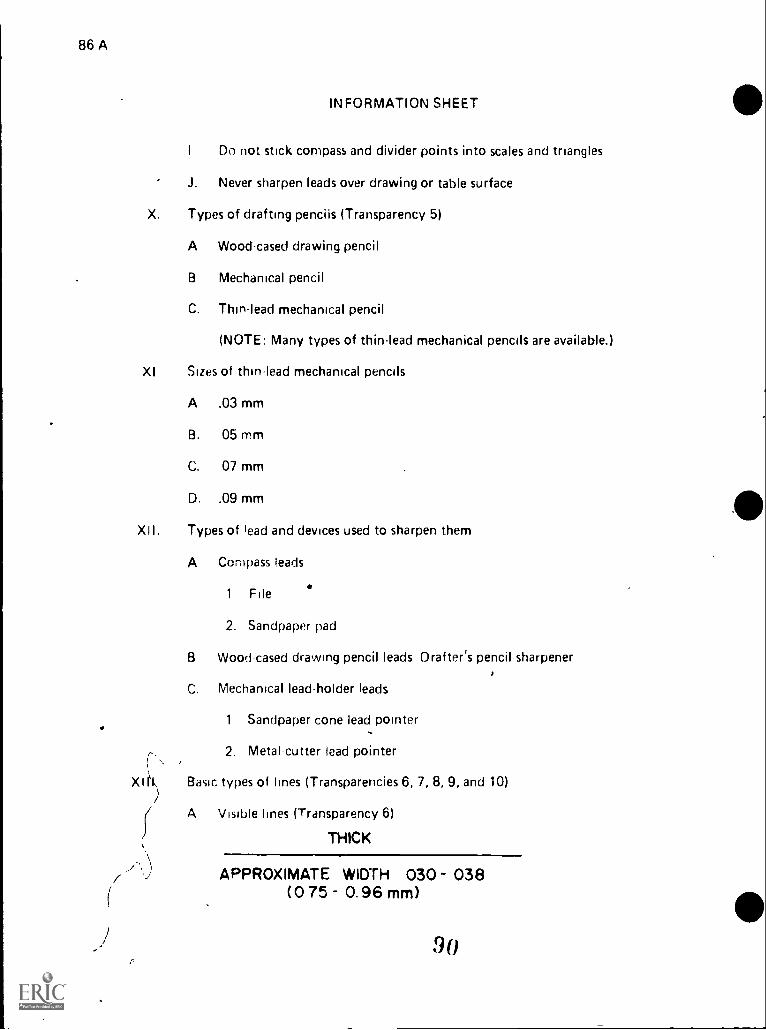
86 A
INFORMATION SHEET
I Do not stick compass and divider points into scales and tnangles
J. Never sharpen leads over drawing or table surface
X. Types of drafting pencils (Transparency 5)
A Wood-cased drawing pencil
B Mechanical pencil
C. Thin-lead mechanical pencil
(NOTE: Many types of thin-lead mechanical pencils are available.)
Xl Sizes of thin-lead mechanical pencils
A .03 mm
B. 05 mm
C. 07 mm
D. .09 mm
XII. Types of lead and devices used to sharpen them
A Compass leads
.1 File
2. Sandpaper pad
B Wood-cased drawing pencil leads Drafter's pencil sharpener
C. Mechanical lead-holder leads
1 Sandpaper cone lead pointer,2. Metal-cutter lead pointer
,
Basic types of lines (Transparencies 6, 7, 8, 9, and 10)
A Visible lines (Transparency 6)
THICK
APPROXIMATE WIDTH 030 038(0 75 0.96 mm)
90

gi
INFORMATION SHEET
B. Hidden lines (Transparency 6)
1/8 .12 (3.2 mm) --01 h THIN -14 1/32 .03 (0. 8 mm),
APPROXIMATE WIDTH .0(5-.022(0.38 0.55 mm)
C. Section lines (Transparency 7)
THIN
APPROXIMATE WIDTH .015-.022(0.38 0.55 mm)
D. Center lines (Transparency 7)
..--3 to I 1/2
1/8 .12 (3.2 mm)
r/4 ",- 1/16 .06 (I.6mm)IFT5-150(19-38mm) THIN
APPROXIMATE WIDTH .015-.022(0.38- 0.55 mm)
E. Extension lines (Transparency 8)
THIN10.11 ip-
APPROXIMATE WIDTH .015- 022
(0.38 0.55 mm)
91us
4
D I - 87-A
,

88 A
INFORMATION SHEET
r)i nens,on lines (Transparency 8)
c
THIN
aPPRGxIMATE WIDTH 015-.022(0 38- 0 55 mm)
G. i dJ(Jer I:nes (Transparency 8)
/- ( SHOULDER OPTIONAL APPROXIMATELY/ 1/4", LONG )//THIN -----\\
\ APPROXIMATE WIDTH 015 022(0 38 0 55 mm)
Ctittini; plane I:ne (Transparency 9)
1/16 06 (I 6 mm) --
1
1/8 12 (3. 2 mm)1
3/4 to I 1/2.75-150
(19-38 mm)
THICK
APPROXIMATE WIDTH 030 038(0 75 0 96 mm)
I Short break lines (Transparency 9)
THICK
FREEHAND
-_/----APPROXIMATE WIDTH 030 038
(0.75 0 96 mm)
92

INFORMATION SHEET
J. Long break hnes (Transparency 10)
3/4 to H/2
THIN
.75 i.50(19- 38 mm)
FREEHAND
APPROXIMATE WIDTH 015-.022(0.38- 0 55 mm)
K. Phantom lines (Transparency 10)
THIN
3/4 to II/1/8 .12 (3.2 mm)-1 r75-1.50
(19-38m4
APPROXIMATE WIDTH.015 .022(0.38 -0.55 mm)
L. Stitch lines
.06 ( 1.6 snm )
D I 89-A
(NOTE The stitch line is used for !ndic,iting a stitching or sewing process.)
THIN.06 (16 mm) 1/16 .06 ( 1.6 mm )
II i!
1,.1:'R0XIMATE WIDTH 015 .022 (0 38- 0.55)
1
(1/64 016 (0 35mm)
(NOT Some companies are not willing t()11,,. the Iwo; stdod,lok, dierefore)the hidden dnd stitch lines \Add havi, d medium line width )
93

90 A
1 0
INFORMATION SHEET
M. Chain lines
(NOTE: The chain line is used to indicate that a surface or surface area is toreceive some additional treatment specified on drawing.)
L._3/4 to 1 1/2
THICK1/8 .12 .2
_..1 11= .75-150
(19-3 emm)
APPROXIMATE WIDTH.030 .038(0.75 -0.96 mrn ) -011,-1/16 .06 (1.6mm)
N. Border lines
THICK
APPROXIMATE WIDTH .030 - .038(0.75- 0.96 mm)
XIV. Pencil lead grades (Transparency 11)
A. Hard
1. 9H
2 8H
3. 7H
4. 6H
5 5H
6. 4H .94

..
INFORMATION SHEET
B. Medium
1. 3H
2. 2H
3. H
4. F
5. HB
6. B
C. Soft
1. 2B
2. 3B
3. 4B
4. 5B
5. 6B
6. 78
XV. Uses of leads by their general clrss
A. Hard leadsM1t
1. Wherever extreme accuracy is required
2. Guidelines for lettering
3. Construction lines
B. Medium leads
1 General burposetwork
2. The softer of these are used for
a. Lettering
b. Technical sketching
c. Arrowheads
d. Any freehand work on drawings
95
DI-91-A

92 A
I
t.
INFORMATION SHEET
The harder of these are used for:
a Lint, work on drawings
b. The 2H and H leads are the two leads most often used on pencildrawings, which will be reproduced
Jo t leads
1. Fine art drawing
2. Architectural rendering
3. Production illustration
4. Lettering
XVI Disdthantages of hard and soft leads
usadvantages of hard leads--Use mrestricted, apt to be too light
(NOTE: Humidity is sometimes a problem. On humid days the paper absorbsmoisture from the atmosphere and becomes soft, it will expand and becomeI rinkled. When this occurs a softer lead will be needed to offset the soft-
enir4ig of the paper. For example if the drafter has been using a 4H lead, use a2H until the weather clears up.)
b. Disadvantages of soft leads
1 Will result in smudged, rough lines
2 Difficultjo erase_.
_3 Must l-IP continually sharpened
..( :-,t.iggestod line widths for iinework
A Thick
1. , Visit
2. Viewing plane or cutting plane
3 Short-break
4. Chain hne
5. Border line
B. Thiri
_ 1. Center (symmetry line)
. 96
,
4
.-)

D I 93-A
2. Section
3. Dimension
4. E xtension
5. Leader
6. Long break
INFORMATION SHEET
,
7. Phantom or adjacent-part
8. Hidden line
9. Stitch line
(NOTE: To obtain a sharp hne always rotate the drafting pencil slowlyas you draw.)
XVIII. Advantages and disadvantages of ink, lead, and plastic lead
A. Ink
1. Advantages
a. Reproduces a clean, dense line
h Does not smudge
c. Revisions of original drawings can be made easily with no"ghost" or damage to drawing surface
ri Ink lines are completely readable through microfilm reduction and.blowbac.k
..
2. Disadvantages
d Messy
b Hard to clean up
c Time consuming maintenance of pens
B. ,Lead
1 Advantages
d Quick
b Easy\
9 7
I
-N
94 A
INFORMATION SHEET
2. Disadvantages
d. Smudges easily..
b. Leaves fuuy lines after reproduction
c. Point dulling and breaking
C Plastic lead
1 Advantages
a. Does not smudge as easily as lead
b. Quick
2. Disadvantages
a. Can only be used on polyester film
b. Point dulling and breaking
c Lack of adequate opacity
d. Extremely brittle
XIX. Comparable reproduction qualities of 1,:ad, plastic lead, and ink
A Lead Acceptable
B. Plastic lead -Good
l'C Ink Excellent
XX Nonreproducible lead--A lead that will not reproduce by standard reproduc-tion machine% It is used for layout work, only
(NOTE This lead can be obtained for a wood cased drawing pencil, or for a05 mm thin lead mechanical pencil.)
98
ar,

A
Standard Triangles
A

Three Types of Compasses
Compass, Lengthening Bar,Pen Attachment
Friction Compass
Jet Bow Compass
OSpeed Bow Compass
Beam
Connector Pen
Point_-NOM
Extension Beam
Beam Compass
Divider orCompass I Pen
Bow tompass
Ratchet Bow Compass
101
D I - 97A
Pencil
V
Drop Spring Bow Compass
TM 2

.
Three Types of Dividers
1. Friction Divklers
VERNIER, ADJUSTING
GRADUATIONS KNOB
.,1 t1
2. Bow Dividers
3. Proportional Dividers
102
D I - 99-A
TM 3t

6=zifilla111 a"- Iiia
s.
Types of Drafting Pencils
DRAWING PENCIL
Sharp Conical Point Grade Mark
For General Linert;ork and Lettering Do not sharpen this end!
MECHANICAL PENCIL
j03
Drafting Pencil Leads
Available in all grades
Thin - Lead Mechanical pencil
Thin Leads Require no Sharpening
10 1
0-6>

Tools Used To Erase And/OrClean A Drawing Surface
141r11111681.,4,:;.....:4:*. POI
1. ERASERS
2. ERASINat"'*SCI
so t h 1,040
A W
D I I 03-A
f r ott C
3. CLEANING PAD
4. DUSTING BRUSH
5. ELECTRIC ERASER
105TM 5

.,
Visible Lines and Hidden Lines
h
ylOTH AND CHARACTEROF LINES
LINES APPLICATIONSu
.,
TH
Pill)ICK
VISIBLE UNEAPPROXIMATE WIDTH .030 - .038
(0.75 - 0.96 mm)
Y.
1/32 0.3(0.8mm) .lr- THINHIDDEN LINE
APPROXIMATE WIDTH .015 - .022(0.38-0.55mm)_
,

iSiction Lines and Center bites
WIDTH AND °CHARACTERUNES APPLICATIONS
OF LINES
Ra, 42THIN
SECTION LINE APPROXIMATE WIDTH .015-.022 Pr.11111
i 11
(0.38 - 0.55 rnm)
3/4 to I 1/2 .75-1.50(19 38mmJ7 V8 .12 (3. 2 mm
I --Tt4t..V16 .06 (L.6rTwn)
CENTER LINETHIN
APPROXIMATE WIDTH .015-.022
(0.38- 0.55 mm)
-4 109109

Extension, Dimension, and Leader Lines
THIN
1-*APPROXIMATE WIDTH .015 .022(0.38 0.55 mm)
3. 50
DIMENSION LINE
3. 50
MUM' IOW
IMII
i
LEADER LINETHIN APPROXIMATELY .010WIDE
(SHOULDER OPTIONALAPPROXIMATELY 1/4" LONG)
0
NMI
- E XTENgION LINE

a
Cutting Plane Lines and Short-Break Lines
WIDTH AND CHARACTEROF LINES
LINES APPLICATIONS
VIEWING PLANE ORCUTTING PLANE LINES
1/16 .06 (1.6 mm)
1 MININ11
.3/4 to 1 I/A
75-1.50 I
09-38 mm)
APPROXIMATE WIDTH .030-.038(0.75 - 0.96 mm)
1/16 .06 (I.6mm)
L Li r 14 1/4 25 (6.4 mm)
011011uSHORT BREAK LINE
THICK
FREEHAND
APPROXIMATE WIDTH .030-.038(0.75- 0.96 mm)
412
113

Long-Break Lines and Phantom Lines
LONG BREAK LINE 62, 4 to 1 1/2
THIN p5-1.50A(19-38 mmV
APPROXIMATE WIDTH .015- .022(0.38 - 0.55 rnm)
Phantom Line
.11
1/8
Thin 1/161:1 IF-3/4to1 1/21
Approximate Width .010
115

VIEWING PLANE LINE
EXTENSION LINE
a rI
Line Applications
DIMENSION LINECENTER LINE
HIDDEN LINE
_ _
0 1 - 115A
/I
BREAK LINE
CUTTING PLANE LINE
VISIBLE LINE
CENTER LINE(PATH OF MOTION)
LEADER
it
PHANTOM LINE4. COVER
SECT 11-6
SECTION LINE
116
I
TM 11

Penci Lead Grades
9H 8H 7H 6H 5H 4H1
Hard
t
,
3H 2H H F HB BI
Medium
#
i 17
B 3B 4B 5B 6B 7BI
Soft
_
,
..
...

:
%
i
D I - 119A
BASIC TOOLS AND LINESt UNIT III
ASSIGNMENT SHEET #1-DRAW LINES ON A DF1AWING MEDIUMUSING GRAPHITE AND PLASTIC LEAD
Directions: Make three drawings .
41. Make two drawings on a sheet of vellum, one with plastic lead and one with graphite
: ioad (size to be determined by the instructor). .
2. Make one drawing on a sheet of polyester film (size to be determined by the instruc-
tor)
3. Include the complete alphabet bf lines
4. Show variations in line width
5. Reproduce on the print machine
t-.
.,
..
11 9

D I - 121A
BASIC TOOLS AND LINESUNIT III
ASSIGNMENT SHEET #2-SHARPEN A COMPASS LEAD OR MECHANICALLEAD-HOLDER LEAD WITH A CONICAL OR A WEDGE POINT
#I. Procedure
(NOTE: A properly sharpened lead, both lead holder and compass, is extremelyimportant because a dull lead produces fuzzy, rough lines. Only a sharp lead canproduce the clean, sharp, dark lines needed for proper reproduction.)
A. Sharpen a mechanical lead holder in a lead pointer (Figure 1)
1. Extend the load approximately 1/2" ou't of the mechanical lead holderand insert it into the opening in the top of the lud pointer (Figure 1)
2. Rotate the lead holder in the pointer until it is sharpened into a clean,
sharp point
3. Check the point by drawing a clean, sharp line on paper
,
(NOTE:. If th(1 point produces .a fuzzy, rough line, sharpen it agaiin.). -
FIGURE 1
1 21)
i

122.A
ASSIGNMENT SHEET #2
B. Sharpen a compass point
1 Extend the lead approximately 1/2" but of the compass ard placeit at a 3(7 angle on the sandpaper p igute 2)
2 Move the compass lead back and forth over the sandpaper until itforms a smooth, wedge shaped point` on a long cut rr ;TirC 2) t.
3. Turn the compass lead to each side at a 30° angle on 1.he sandpaperand make smooth side cuts slightly shorter than the long cut on thewedge (Figure 2)
4. Check the point by drawing a clean, sharp line on paper
(NOTE: If the pomt produces a fuzzy, rough line, sharpen it again I
.4v.at
(t Problems
c 7 LIPL,1k,
_,
FIGURE 2
f I.`.11."
A. Direct.ons Sharpen a mechanical lead-holder lead. Follow the procedures outlined on th;s assignment sheet.
B. Directions: Sharpen a compass point Follow the procedures outlined onthis page.

4
D I 123-A
BASIC TOOLS AND LINESUNIT III
ASSIGNMENT SHEET *3-DIVIDE A CIRCLE INTO 24 PARTSOF 15' BY USING THE 30760" AND 45' TRIANGLE
I. Procedure
A. Use the established center point and center lines as a reference point fromwhich two standard triangles can be used to find the first 15.Nangle (Figure
1)
B. Use one triangle to find the 30" angle next to the first 15" angle
C. Use one Wangle to find the 45" angle next to the first 30' angle
D. Use one triangle to find th660' angle next to the first 45" angle
E. Use two triangles to find the 75' angle next to the 60' angle
F. Use one triangle to find the 90" angle next to the first 75" angle
G. Continue with triangles and a parallel bar until the circle has been dividedinto 24 parts and each angle has been correctly labeled
FIGURE 1
122
0

-
al124-A
1
I
II. Problem
%.
ASSIGNMENT SHEET *3
e4
Directions: Divide a circle into 24 parts of 15' using only standard trianglesand a parallel bar following the procedure demonstrated in Figure 1
,
*4
t
.. ..
4i ....
0
i
1 4r) ri1 .. a)
- ..

4D I - 126-A
BASIC TOOLS AND LINESUNIT III
. ASSIGNMENT SHEET #4--USE A COMPASS TODREW CIRCLES AND ARCS
-e
I. ProcedUie
.L
... ..
.._
(NOTE: A c mpass is used to draw cirCles or arcs that are too large or different insize from a circle template.)
a
A. Set the radius to be used (Figure 14)
(CAUTION:' Do not place the compass directly on the scale because this1 practice'could eventually damage the scale.)
B. After radius is determined, start the circle by holding the compass handlebetween the thumb and forefinger (Figure 1-b)
y.)
,
C. Sot Compass point at center, then use one hand to adjust the compassto the determined radius (Figure 1-c)_
D. Complete ihe circle by rotating the compass in a clockwise direction
E. Use the scale to check accuracy of the diameter before darkening lines
,
&
,
124
,

126-A
:-
ASSIGNMENT SHEET #4
I I. Problems
A. Directions. Use "A" size drawrai vehum with standard horde; and titleblcck and divide the woNag. space into two equal parts. Constiuct a 31/2" square centered on the lett side of the working space and constructa figtire like the ow: shown in Figure 2 in that space. Draw 1 3/4" radius arcsa$ A, 13, C,-and D., and etbstruct small arcs so that they intersect as shown inFigure 2. Complete the problem by adding center lines.
(NOTE ..0mit radius lines A, B, C, and 0 from finished drawing.)
HGURE 2
B Directions: Construct a 3 1/2" square centered on the right side of thevellum used for Problem A and construct a figure like the one shown inFigule 3 in that space. Construct a 3" circle from center point, and thenronstruct ,four 1 3,'4" radius arcs usinti colliers or squares as center points.
/ Draw an inner cirrle so that it intersects as shown in Figure 3, and completethe problem by adding center lines.
(NOTE. Omit radius lines A, B, C and D from finished drawings.)
FIGURE 3

BASIC TOOLS AND LINESUNIT III
ASSIGNMENT SHEET #5-USE A DIVIDER
I. Procedure
D I - 127-A
(NOTE: A divider is used to transfer a dimension from one point to another
or to subdivide a line into ',Given number of equal parts.)
A. Divide a line into a given number of equal parts
B. Set one point of the divider at one end of the line and use one hand to adjustthe divider to approximately 1/3 the distance of the line (Figut 1-a)
(NOTE: Distance will change depending upon number of divisions.)
C. Swing the divider clockwise to the second point on the line (Figure 1b)
D. Swing the divider counterclockwise to the third point on the line (Figure
1-c)
(NOTE: If spacing is too short or long, lengthen or shorten the dividerspacing slightly and try spin; this is a trial and error method, but a usefulmethod to practice.)
FIGURE 1
0
126
(c)

128-A
II. Problem
Directions: Use "A" size vellum with standard border and title block and con-struct a 4" square in the center of the working space. Usiqg Figure 2 as an exam-ple, divide lines A-D and B-C into seven equal parts locatirtg the corners of thesquares. Construct the squares and complete the figure by adding canter lines.
..
.
I
FIGURE 2
-
1 01"
.,.

e
BASIC TOOLS AND LINESUNIT III
ASSIGNMENT SHEET #13-MEASURE ANGLES WITH A PROTRACTOR
I. Procedure
D I - 129-A
A. Place the base line or 180 line of the protractor along one leg of angle to bemeasured with vertex of angle at marked center point of protractor (Figure1)
B. Starting at zero, road up the side of the protractor right or left depending onthe angle being measured
e
FIGURE 1
,

130-A
ASSIGNMENT SHEET #6
II. Problem
Directions: Measure and record the angles shown in the blanks provided
.,

. D I - 131-A
BASIC TOOLS AND LINESUNIT III
ASSIGNMENT SHEET #7--USE AN IRREGULAR CURVE TO CONSTRUCTA CURVED LINE
I. Procedure^
(NOTE: The irregular curve is used to construct noncircular arcs.)
A. Move the curve around to connect three or more given points
B. Connect these points
C. Move curve to new position using at least two points previously given
D. Extend line to join new points (Figure 1)
FIGURE 1
. 13u

#
--
II. Problem
s
ASSIGNMENT SHEET *7 .
Directions: Complete the following figure using irregular curve.
# .
, FIGURE 2
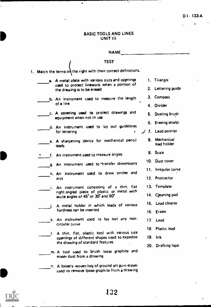
BASIC TOOLS AND LINESUNIT III
NAME
TEST
1. Match the terms o the right with their correctdefinitions.
a. A metal plate with various slots and openingsused to protect linework when a portion ofthe drawing is to be erased
b. An instrument used to measure the lengthof a line
c. A covering used to protect drawings andequipment when not in use
d. An instrument used to lay out guidelinesfor lettering
e. A sharpening device for mechanical pencilleads
f. An instrument used to measure angles
9. An instrument used to -transfer dimensions
h. An instrument used to draw circles andarcs
i. An instrument consisting of a thin, flatright-angled piece of plastic or metal withacute angles of 45 or 30 and 60'
I.
_
A metal holder in which leads of varioushardness can be inserted
k. An instrument used to lay out any non-circular curve
I. A thin, flat, plastic tool with various sizeopenings of different shapes used to expeditethe drawing of standard features
m. A tool used to brush loose graphite anderaser dust from a drawing
n. A loosely woven bag of groUnd art gum eraserused to remove loose graphite from a drawing
132
0 I - 133A
1.
2.
3.
4.
5.
6.
7.
8.
Triangle
Lettering guide
Compass
Divider
Dusting brush
Erasing shield
Lead pointer
Mechanicallead holder
9. Scale
10. Dust cover
11. Irregular curve
12. Protractor
13. Template
14. Cleaning pad
15. Lead cleaner
16. Eraser
17. Lead
18. Plastic lead
19. Ink
20. Drafting tape

134-A
-
o. A device used to remove pencil lines andgraphite smudges from a drawing
-P. A styrofoam pad or tissue paper used toremove loose graphite from a pencil lead after
it has been sharpened
_q. A specially prepared tape that does notharm surface of table or drawing media
r. Composed mainly of carbon in colloidalsuspension and gum. The fine particlesof carbon give the deep, dark, black, appear .ance to the ink, and the gum makes it quickto dry and waterproof
s. Made of graphite with kaoline added invarying amounts in order, to make the eigh.teen grodes from the hardest (9H) to the
softest (78)
t. Composed of varying amounts of graphitewith plastic
2., Identify the angles found on the two standard triang:es.
.00
a.
b.
C.
d.
,
Jr.........
b. C.
;.
%

I
s..
3. State the purpose for using a standard triangle.i
D I -, 135-A
4. List ihree types of compasses.
a.
b.
f i
-
S. Identify the three types of dividers.
a.
6. List four types of irregular curves.
a.
b.
C.
d.
NI
le
\
7. List five types of common templates.
a.
b.
C.
d.
e.
13 1e

136-A
8. Identify tools used to erase and/or clean a drawing surface.
a. b.
4.0
c d.
e.
ma?
4Q.- - ..,........ .1
rietai*
9. Select true statements concerning rules for maintenance and care of drafting tools andequipment by placing an "X" in the appropriate blanks.
a. Do not bend templates sharply
b. Ternpiate and scales can be used as a straight edge for cutting
c. Keep ah ingruments clean and dry_d A cin.l template can be used as an eraser shield
e. Do not hit scales and triangles on edges10
f. Compasses and dividers cannot be over extended
g. Clean plastic tools with soap and water only
,1 o) am1 ua
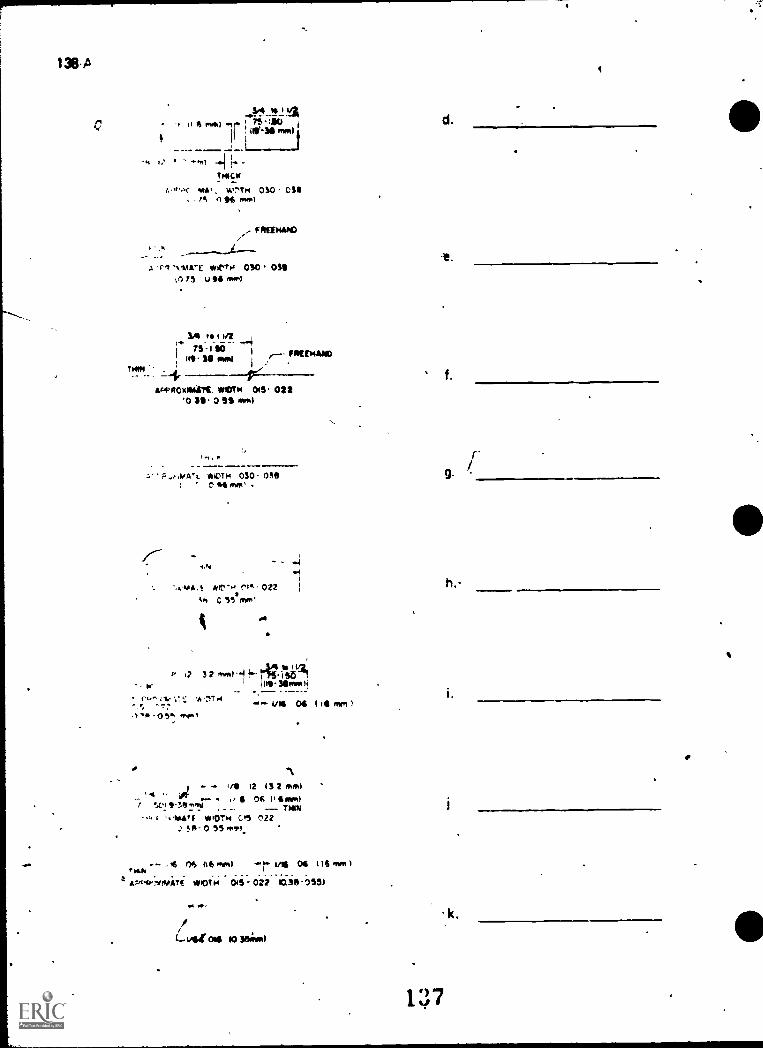
Z." I
*4
Polon 01 900 ISA
(no - of pi en - SO osioio
WU, SI) 90 90 Imm yo 91, «-
-64., SS 0 - r 14.1.0im hVs.
9 .
fri WY. t 11 90 "'" . 14.4' /1
law 941 0 91/4 I 40-111.4.'
MIA:, V, :;
II wain t t*i Now
g,i es
fro
.40464 LS 0 ZZO - .IJ
)
iii0 OSO I41.04* ,
NAV Sfi C -It 0, 880 MOM -3414111099,0
.1
New It 14) --
C4904.3394 as s-gi
I
1,T Wt 4-4
44044 94 n te StO OS0 )44.44*
-
*MON
(+Ami 94 lt IIS0 OtO NU:A
N3114
-
J.. If .0" 11C41)
ee
- .
VIC

TON-
APPROxiMATE ROTH 015 02210 51- 0 55 mm)
THICK
*PROMOTE WIDTH 030 - 030tO 75-0 Mow)
3/4r 75-1210
1813 2 km..3
Newman m-*a 11
030 -1072-004 own -46-1/111 04 Mimi
14. Name the 18 types of leads from hard to soft.
b.
C.
in.
n.
m.
h. n.
d. j.
e.
f.
I. p.
I. r.
D l 139-A
15.. Match the general classes of leads on the right with their uses.
a. The softer of these are used for technical 1. Hard leads
sketching, arrowheads, and any freehandwork on drawings 2. Medium leads
b. Wherever extreme accuracy is required 3. Soft leads
c. Construction lines
d. Fine art drawing
e. Architectural rendering
f. General purpose work
g. Lettering, (exclusively)
h. Production illustration
i. Line work on drawings
j. Guidelines for lettering

140-A
16. Distinguish between the disadvantages of hard and soft leads by placing an "H" next tothe disadvantages of hard leads and an "S" next to the disadvantages of soft leads.
a. Will result in smudyed, rough le es
b. Use is restricted, apt to be too light
c. Difficult to erase
d. Must be continually sharpened
17 Select line widths for linework by placing in the appropriatethick and a "TN" for thin.
a: Visible
b. H.dden
c. Dimension
f. Section
g. Short-break
h. Extension
d. Long break i. Phantom oradjacent-part
e. Leader
18. Distinguish between the advantages and disadvantagesplaciniA an I" next to the advantages ot ink, anand a P" next to advantages of plastic lead.
a. Quick and easy
b. Can offiy be i sect on polyester film
c. Extremely brittle
d. Does not smudge
e Hard to clean up
Does not smudge as easily as iead
Leaves fuzzy lines after reproduction
h Lines are completely readable through microfilm reduction and
1 Does not smudge
Hard to clean up
k Messy
Rtbroduce% a ciean, dense line
m. Point dulhng and breaking
blanks a "TK" for
j. Stitch
k. Center
I. Viewing plane orcutting plane
m. Chain line
n. Border line
of ink, lead, and plastic lead bynext to the advantages of lead,
blowback

D it - 1411%
n. Revisions of original drawings can be made easily with no "ghost" or damageto drawing surface
o. Time consuming maintenance of pens
19. Match the reproduction on the right with their correct medium.
a. Lead
b. Plastic lead
c. Ink
20. Describe nonreproducible lead--
1. Acceptable
2. Good
3. Excellent
21. Draw lines on a drawing medium using lead and plastic lead.
22. Sharpen a compass lead or mechanical lead-holder lead with a conial point anda wedge point.\
23. Dividca circle into 24 parts of 15 by using the 30°/60° and 450 triangle.-
24. Use a. compass to draw circles and arcs.
25. Use a divider.
26. Measure angles with a protractor.
27. Use an irregular curve to construct a curved line.
(NOTE: If the activities in item 21-27 have not been completed prior to the test, askyour instructor when they should be completed.)
c

2.
a. 6 e. 7b. 9 f. 12c. 10 g. 4d. 2 h. 3
a. 90°b. 30'C. 60°d. 45
BASIC TOOLS AND LINESUNIT III
ANSWERS TO TEST
i. 1 m. 5 q. 20
i. 8 n. 14 r. 19k. 11 o. 16 s. 17
I. 13 p. 15 t. 18
D I - 143-A
1) -I.
3. To provide a straight edge for drawing vertical or inclined lines at any angle that is amultiple of 15 degrees.
4. a. Frictionb. Bowc. Beam
5. a. Frictionb. Bowc. Proportional
6. a. Ships curveb. Flexible curvec. Rule curved. French curve
7. Any five of the following:
a. Circle templateb. Ellipse templatec. Architectural templated. Isometric ellipse templatee. Piping templatef. Structural steel shape templateg. Hex bolt head templateh. Thread templatei. Plumbing templatej. Civil template
8. a. Eraser shieldb. Cleaning padc. Dusting brushd. Erasere. Electric eraser
9. a, c, e, g
10. a. Wood-cased drawing pencilb. Mechanical pencilc. Thin-lead mechanical penco
1 1 1
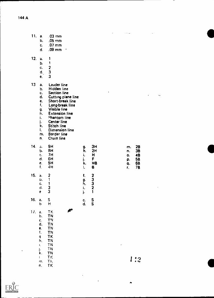
144 A
11. a, .03 mmb. .05 mmc. .07 mmd. .09 mm
12. a. 1
b. 1
C. 2d., 3e. 3
13 a. Leader lineb. Hidden linec. Section lined. Cutting plane linee. Short-break linef. Long-break lineg. Visible lineh. Extension lineI. Phantom linej. Center linek. Stitch lineI. Dimension linem. Border linen. Chain line
14. a. 9Hb. 8Hc. 7Hd. 6He. 5Hf. 4H
15. a. 2b. 1
c. 1
d. 3e 3
16. a. S
b H
11. a. TK itab. TNc. TNd. TNe. TNf. TNq TKh. TN1. TNI. TNk. TN
1 TK1 4 9A 4.rTI. TI\
n. TK
g. 3H m. 28h. 2H n. 38i. H o. 48j. F p. 58k. HB q. 68I.
f.
8
2
r. 78
9.h.i,j.
c.d.
3321
SS

6
18. a. Ld. I
f. P
19, a. 1
b. 2C. 3
20. A lead that will not reproduce bylayout work, only.
21. Evaluated to the satisfaction
22. Evaluated to the satisfaction
23. Evaluated to the satisfaction
24. Evaluated to the satisfaction
25. Evaluated to the satisfaction
26. Evaluateil to the satisfaction
27. Evaluated to the satisfaction
0 I - 145-A`
n. I
cstandard reproduction machines. It is used for
of the instructor
of the instructor
of the instructor
of the instructor
of the instructor
of the instructor
of the instructor

-
MAJOR EQUIPMENTUNIT IV
UNIT OBJECTIVE
D I - 147-A
After completion of this unit, the student should be able to operate a parallel bar, adjustabletriangle and an electric eraser. The student should also be able to make adjustments to anelbow drafting machine and a Vtrack drafting machine. This knowledge will be evidencedby correctly performing the pmcedures outlined in the assignment and job sheets and byscoring 85 percent on the unit test.
SPECIFIC OBJECTIVES
After completion of this unit, the student should be able to:
1. Match terms related to major equipment with the correct definitions.
2. Identify parts of a parallel bar.,
3. List three advantages of a parallel bar.
4. Describe the operation of a parallel bar.
5. Describe the use of an adjustable triangle.
6. Identify the parts of mn elbow drafting machine.
7. List four advantages of an elbow drafting machine.
8. Describe the operation of an elbow drafting machine.
9. Identify the parts of a V-track drafting machine.
10. List four advantages of a V-track drafting machine.
11. Describe the operation of a V-track drafting machine.
12. Select rules to remember in the maintenance and care of drafting machines.
13. List four rules related to the use and maintenance of an electric erasing machine.
14. List two factors that determine the type of electric eraser refill to use.
15. Select types of electric refills and their uses.
16. Operate a parallel bar.
17. Operate an adjustable triangle.

148-A
18. Measure angles with the protractor and vernier scale on a drafting machine.
19. Demonstrate the ability to:
a. Make adjustments to a V-track drafting machine to install and align malt&
b. Make adjustments to an elbow drafting machine to install and align scales.
o
t
c 1 15
11

l
.....-...--,--__
0 I - 149-A
MAJOR EQUIPMENTUNIT IV
SUGGESTED ACTIVITIES
I Provide student with objective sheet.iII. Provide student with information, assignment, and job sheets.
III. Make transparencies.
IV. Discuss unit and specific objectives.
V. Discus information, assignment, and job sheets.
VI. Demonstrate and discuss the procedures outlined in the assignment sheets.
VII. Demonstrate and discuss the procedures outlined in the job sheets.
VIII. Have students perform activities on job sheets before assignments sheets arestarted.
IX. Demonstrate the set-up and accuracy of a parallel bar.
X. Discuss the advantages and disadvantages of an electric erasing machine.
XI. Have vendors give demonstrations on new products.
XII. Give test.
INSTRUCTIONAL MATERIALS
lkI. Included in this unit
A. Objective sheet
B. Information sheet
C. Transparency masters
1. TM 1-Parts of a Parallel Bar
2. TM 2-Adjustable Nellie
3. TM 3-Parts of an Elbow Drafting Machine
4. TM 4-Parts of a Standard Protractor Head
5. TM 5-Parts of a V-Track Drafting Machine
1
I
,

150 A
II Assignment sheets
1. Assignment Sheet #1--Operate a Parallel Bar
2. Assignment Sheet #2--Operate an Adjustable Triangle
3. Assignment Sheet #3--Measure Angles with the Protractor and Vern
Scale on a Drafting Machine
E. Answers to ass,gnments sheets
F Job Sheets
1. Job Sheet #1--Make Adjustments to a V-Track Drafting Machine toIr,stall and Align Scales
2. Job Sheet #2--Make Adjustments to an Elbow Drafting Machine toInstall and Align Scales
G Test
A..swer; to test
11, tercnoes:
A. Brnwn, Waiter C. DI afting for Industry. South Holland, IL: Goodheart-Micox Company, Inc., 1974.
B Giesecke, Frederick E., et al. Technical Drawing. New York, NY, 10022:MacMillan Publishincj.Co., Inc., Seventh Edition, 1980.
C. Spence, Miidm P. Drafting Technology and Practice. 'Peoria, IL 61611:Chas. A Bennett, Company, Inc., 1973.
Jensen, Cecl! and Jay Helsel. Engineering Drawing and Design. St. Louis, MO6.3100: Gregg Division/McGraw-Hill Book Company, 1979.
Dygdon, John Thomas and Henry Cecil Spencer. Basic Technical Drawing.New York, NY 10022, MacMillan Publishing Co., Inc., 1968.
D I - 151.A
MAJOR EQUIPMENTUNIT IV
INFORMATION SHEET
I. TIMM and defintions
A. HorizontalParallel to the plane of the horizon
B. Vertical-A line straight .up and down, perpendicular to the horizontalplane
C. Drawing media-Any type of drawing material upon which an object isgraphically represented
D. Working surface-Any surface such as a drafting board or desk used tosecure drawing media
E. Perpendicular-At a 90* angle to a given plane or line
F. Parallel-Two lines or surfaces side by side, equal distances apart at all pointsI .*?
G. Working edge-An edge used as a point of reference, such as the edge of adrawing board or T,square
H. Ellipse-A foreshortened circle with a major and minor diameter
I. Vernier-A measuring device consisting of a main fixed scale and a smallergraduated scale that slides to obtain fine measurements
IL Parts of a parallel bar (Transparency 1)
A. Cable
B. Bar
C. Cable clamp
D. Cable pulleys
E. Tension bracket
III. Advantages of a parallel bar
A. Easy to make long-horizontal lines
B. More accurate than a T-square
C. Very little maintenance
D. Simple to operate
^

152.A
. ..
INFORMATION SHEET
IV. Operdtiun of a parallel bar--A parallel bar is a long flat bar similar to a T-squarethat has a hollow area in its middle through which cables pass. These cables workthrough a series of pulleys, and the ends are attached to a tension bracket. Thecdhles allow the bar to move in a parallel motion up and down the workingsl .1 t ace (Transparency 1)
V Use of an adjustable triangle.-An adjustable triangle is used in combinationwith a T-square or parallel bar to lay out lines that are not at the standard 156inc.rement (Transparency 2)
VI. Parts of an elbow drafting machine (Transparencies 3 and 4)
A. Clamp
B. Upper arm
C. Lower arm
D. Elbow brake
F.. Standard protractor head (Transparency 4)
F. Vertical scale
G. Horizontal scale
H. Protractor
I. Handle
J. Base line wing nut
K. Index thumbpiece
L. Protractor brake Wing nut
M. Chuck plate
N. Vernier plate
0. Scale chuck..
P. Adjusting screw
V H. Advantages of an elbow drafting machine
A. Increases Braking output
B. Requires fewer tools to operate
oC. Less expensive than parallel track machine
D. Can be aligned to any base line
el
..

Af
I 153-A
di X
INFORMATION SHEET
E. More accurate than separate protractor instrument
F. Can be operated from any side of the drawing desk
VIII. Operation of an elbow drafting machine--An elbow drafting machine has a pro-
tractor head which can be adjusted to.any angle weasurement acidrate to the
nearest 5 minutes of a degree. The protractor head moves in any direction on
the working surface. The head is mounted at the end of two arms hinged in the
middle with an elbow swivel joint This allows the drafter to make parallel firms at
any angle.
IX. Parts of a V-track drafting machine (Transparencies 4 and 5)
A. Mounting clamp
B. Horizontal track
C. Vertical track
D. Standard protractor head (Transparency 4)
E. Vertical scale
F. Horizontal scale
G. Vertical motion brake
H. Horizontal motion brake
I. Protractor head pivot point
X. Advantages of a V.track drafting machine
A. Simple to operate
B. Versatile
C. Accuracy is better maintained
D. All areas of drawing board accessible
E. Few working parts
Xl. Operation of a V-track drafting machine--The V-track machine has a protrac-
tor head which can be adjusted to any angle measurement accurate to the nearest
5 minutes of a degree; this protractor head moves on a vertical track which in turn
moves on a horizontal track. This allows the drafter to make parallel lines in any
direction.
1 .1Cl

154 A
a
INFORMATION SHEET
XI I. Rules to remember in maintenance and care of drafting machines
A. Keep support clamps secured snugly to desk
B Keep scales aligned and tight
(CAUTION: Do not overtighten.)
C. Keep scales clean
D. Keep scales flat on working surface; do not lift machine by scales
E. Keep band tension adjusted properly
F. Protractor head should adjust easily
(CAUTION: Do not force. Check protractor brake wing nut.)
G. Tighten baseline and protractor wing nuts snugly but not too tight
(CAUTION: Do not force.)
H Lift machine by handle to move from posinon to position
L M.ikr. sure scales are never used to cut or tear paper
J. Never use scales as straight edges for cutting vvith a knife
K Never store drafting machine with scales protruding over the edge of thedrat ting table
XIII. Rules for the use and maintenance of an electric erasing machine
A. /Select correct eraser refill for media being used
B. Keep erdser movtng to prevent burning a hole in drawing media and draftingsur face
C erasinq shield to isolate area being erased
O Be careful when plugging and unplugging erasei from an electric recep-tacle
F- Pr event eraser crumbs and foreign inatemil from talling inside workingrn
Hang er,Ist;r on .orik Or place in tray when not is uso
XIV Fdl tor, that ft !ermine type of electric eraser refill to use
A 1 vi4 ,it wwor k

\
INFORMATION SHEET
XV. Types of electric eraser refills and their uses
A. Dark grey-Used to erase ink
B. White-Used to erase pencil lead
C. Pink-Used to erase pencil lead
D. Green soft-Used to erase pencil lead
E. Pink soft--Used to erase pencil lead
F. Standard red--Used to erase pencil lead
G. Nu-Red--Used to erase pencil lead and used with plastic film
H. Vinyl--Used with plastic film
1)
10
Os
D I 155-A
,,

Parts of a Parallel Bar
Cable Cable Clamp
Cable Pulleys
Tension BracketBar
17,3

!
eI
Adjustable Triangle
Adjusting Knob
NOTE: In Closed Position
Triangle forms Standard 450 Triangle
D I 159-A
TM 2

Parts of an Elbow Drafting Machineei.
Upper Arm
Vertical Scale
Lower Arm
WI FIFT I i FIFITIttlIll 11111 ill\
Clamp t
.ttandard Protractor Head
(Transparency 4)
Horizontal Scale
157
0-5;
il.

,
0
Parts of a Standard Protractor HeadAdjusting Screw
Scale Chuck
Chuck Plate
Protractor
Vernier Plate
srl-iii I, II pl 1
BaseplateHandle .
Lill. iiii IIBase Line Protractor Brake Wing Nut
Wing Nut Index Thumbpiece
s
Ill
0_
il*. 151 c..)
x.
153

Parts of a It-Track Drafting Machine
L.,
r
Vertical Track
VerticalMotion-Brake
1.....--boah
HorizontalMotionBrake
, _
\ CI:.Mounting Clamp
Horizontal Track
Vertical Scale
J
Horizontal Scale
, . ,
: `, 1,_ i,4, I
IP
Standard Protractor Head (Transparency 4)Protractor HeadPivot Point 0
,. I0,
1C)f)

D I - 167-A
MAJOR EQUIPMENTUNIT IV
ASSIGNMENT SHEET #1--OPERATE A PARALLEL BAR
I. Procedure
A. Loosen cable clomp as required (Figure 1) s\B. Move parallel bar to bottem limit of drawing surface
C. Both ends of parallel bar should be in contact with tension brackets
D. Place drawing media on working surface so that top edge of parallel bar doesnot catch bottom edge of drawing media
E. Move top edge of parallel bar up and align with top edge of drawing media
(figure 2)
F. Hold drawing media in position and tape corners toworking surface
Adjustment of Parallel Bar
FIGURE 1
TensionBracket
Positioning the paper on the board
G. Tighten cable clamp adjustment as required
FIGURE 2
H. Move parallel bar up and down on the working surface by holding themiddle of the parallel bar and lifting slightly
I rl 9%., ...,
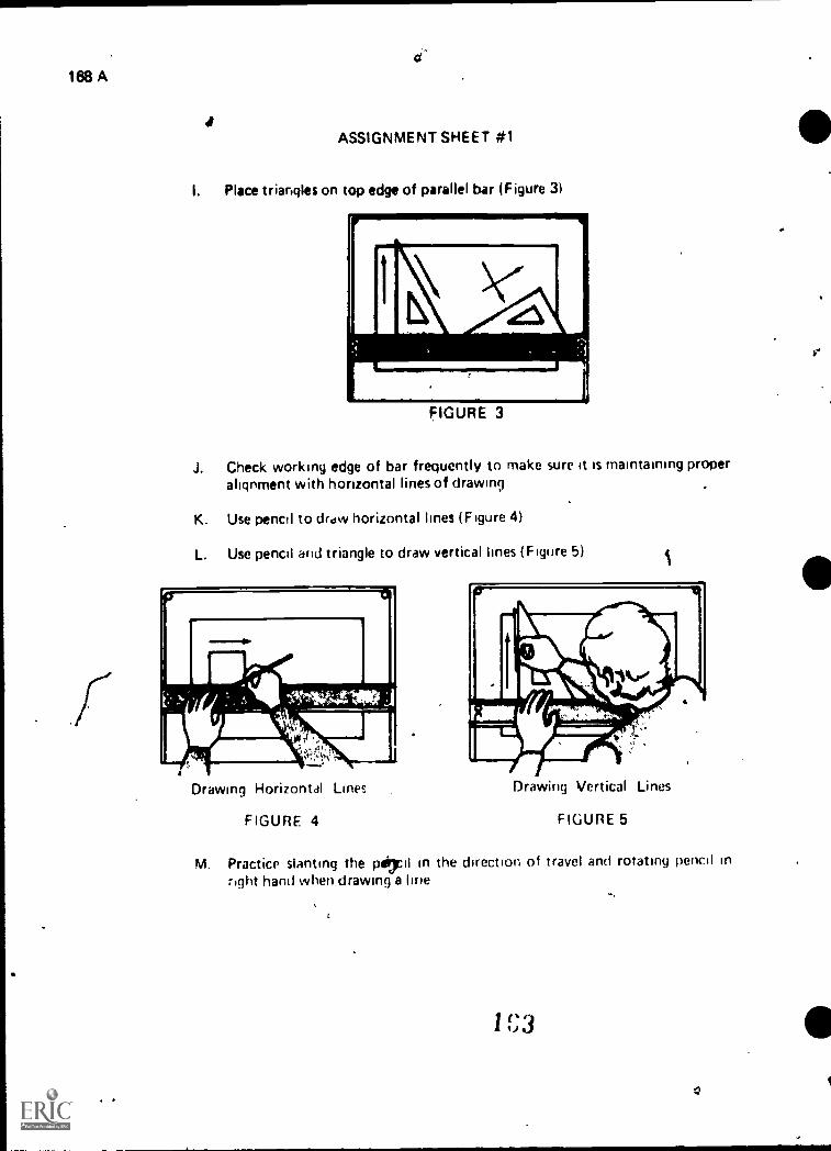
168 A
IASSIGNMENT SHEET #1
I. Place triangles on top edge of parallel bar (Figure 3)
FIGURE 3
J. Check working edge of bar frequently to make sure it is maintaining properalignment with horizontal lines of drawing
K. Use pencil to draw horizontal lines (Figure 4)
L. Use pencil and triangle to draw vertical lines (Figure 5)
Drawing Horizontal Lines
FIGURE 4
i
Drawing Vertical Lines
FIGURE 5
M. Practice slanting the pepl in the direction of travel and rotating pencil inright hand when drawing a line
,
1 (' 3, J
0
I

D I - 169-A
IL ProbleMs
Ar.
ASSIGNMENT SHEET #1
A. Operate a parallel bar and triangles to construct the following figure.
Directions-Use "B" (11 x 17) size drawing vellum with standard border
and title block. Divide the working space into two equal areas. Center
in the left hand area, construct the following figure using proper techniques.
C
--- _
--
_
_
_
I
_
-
-
i
4"
Line BC is Divided into 9 equal parts.Line AB is divided into 6 equal parts.
(NOTE: Work at keeping all object lines the same width and darkness.)
,

170-A
ASSIGNMENT SHEET #1
a
B. Operate a parallel bar and a triangle to construct the following figure.
Directions-Use the right hand area of problem "A" drawing vellum. Con-struct the following grid pattern using proper techniques.
ea.
II
3 3/4 "
4
(NOTE: Accuracy is must" for d drafter, start novv working on accuracyof soacing and keeping all corners clean and sharp.)
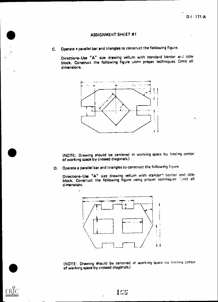
D I 171-A
ASSIGNMENT SHEET #1
C. Operate A parallel bar and triangles to construct the following figure.
Directions-Use "A" size drawing vellum with 3tandard border and titleblock. Construct the following figure usinn proper techniques. Omit all
dimensions.
i
(NOTE: Drawing should be centered in working space by finding centerof working space by crossed diagonals.)
D. Operate a parallel bar and triangles to construct the following figure.
Directions-Use "A" size drawing vellum with standar-1 border and titleblock. Construct the following figure using proper techniques ',mit alldimensions.
(NOTE: Drawing should be centered in working space by finding centerof working space by crossed diagonals.)
1 f; G

D I - 173-A
MAJOR EQUIPMENTUNIT IV
ASSIGNMENT SHEET *2OPERATE AN ADJUSTABLE TRIANGLE
I. Procedure
A. Set required angle on triangle by loosening adjusting knob and settingthe scale (Fig 0.1re 1)
B. Read numbers on lower half of scale, if required angle is greater than 45, theangle will bf the actual angle made by the triangle
C. Read numbers on upper half of scale, if required angle is less than 45, theangle will be complementary to the triangle
i
FIGURE 1
Adjusting Knob
39° 'ft*,
Reading is at 39° --1.-
Parallel Bar Blade
Note-- In Closed PositionTriangle forms Standard 450 Triangle

174-A
\ASSIGNMENT SHEET #2
D. Adjustable triangle can be adjusted so that the long side can serve as the base
line. This changes the direction the individual lines will run (Figure 2)
FIGURE 2
(NOTE: Using long side as base allows you to construct perpendicularlines merely by sliding the triangle.)
.411........39°
dli \ .
51°
39°
3.
51°.----------**1
Adjusting knob
Parallel Bar
a
E. Practice setting various angles and rotating triangle to get various line angles
F Construct parallel hnes by drawing along one edge of the triangle (Figure 3)
1 f' 4LII.
I
I
I

i#
#
D I - 175-A
ASSIGNMENT SHEET #2
G. Slide the triangle along working edge to new position and construct the newline (Figure 3)
Parallel Bar
e

176-A
II. Problem
A
ASSIGNMENT SHEET #2.
Directions-Complete the figures below using a parallel bar and adiustable triangle.
Draw lines parallel to given line through given points
.0.
.0.
Une A-B is aangle to thehorizontal
Draw lines perpendicular to given line through given points
\
D .
0
Line C-D is aangle to thevertical
C
0
*

D I - 177-A
MAJOR EQUIPMENTUNIT IV
ASSIGNMENT SHEET *3MEASURE ANGLES WITH THEPROTRACTOR AND VERNIER SCALE ON A DRAFTING MACHINE
I. Procedure
A. Operaton of the standard protracto head
(NOTE: The standard prctractor head is divided into one degree unitswith a side mounted vernier scale divided into five minute readings. The
protractor has 4 quarters of 90' each.)
1. Push indexing thumbpiece in and rotate head
(NOTE: Protractor will automatically lock every 15 degrees.)
2. Push indexing thumbpiece in and down
(NOTE: This procedure will lock the indexer in the open positionand free the protractor head to completely rotate.)
(CAUTION: NEVER FORCE the head if it does not rotate freely;check protractor brake wing nut.)
8. Measuring angles
(NOTE: The standard protractor head is designed to read an angle to thenearest 5 minutes of a degree. Remember, there are 360' in a circle and 69minutes in one degree.)
1. Locate the "0" on the protractor and the "0" on the vernier scale
2. Push thumb index in
3. Slide the "0" 1 the vernier up or down the protractor until it lines upwith the degree mark needed on the protractor (Figure 1-a)
Example:
1. Assume the vernier is set at a positive,(upward) angle
2. Note the reading is between 7 and 8 degrees
1 7 1

178.A
ASSIGNMENT SHEET #3
3. Find the 5 minute mark on the upper half of the vernier which ismost closely in alignment with a degree mark
(NOTE: The correct reading is 740. The procedure is the same whenreading negative (downward); in this case .the reading is 425'. Refer toFigure 1-b.)
A
C. Setting angles
6
A.
FIGURE 1..1
IP"
1. Release the protractor brake wing nut
2. Push the index thumbpiece in and down to release the index
3. Rotate the protractor arm until the zero of the vernier is at the desireddegree
4. Rotate (slowly) the protractor arm counter-clockwise until the desiredminute mark on the upper half of the vernier is precisely aligned withthe nearest degree mark on the protractor
5. Lock the protractor brake wing nut
(NOTE: The prOcedure for settirg negative angles is essentially thesame except the protractor head is rotated ciockwise.)
172
o

ASSIGNMENT SHEET #3
Il.' Problem
D I - 179-A
Directions-Use "A" size drawing vellum with standard border and title block.Construct the following figure using STD protractor head with vernier scale to lay
out all angles. Sta t point A. Label all corners, show dimensions in table form.Measure and label c sing .angle (B, A, G,) and find the length of G, A to the
nearest 32nd. All ang should be calculated using the deflection method illus-trated in Figure 2 of the example before starting the drawing.
Example: Deflection method
1. Extend line AB beyond object giving 180" line
2. Subtract known 135" from 180' line
3. Set base line scale on 180" line
4. Set protractor head at 45'
5. Construct line B-C
FIGURE 2
0
4

lea.A
ASSIGNMENT SHEET *3
-..
a
A, B 2"
9, C = 2 11 t32"
C. D 1 3/4"
D, E = 2"
E, F = 1 17/32"
F, G - 1 3/4"
G, A B, A. G =
(NOTE: Required angles to draw figure have to be calculatEl Use deflection method.)
171
I

MAJOR EQUIPMENTUNIT IV
A NSW E RS TO ASSIGNMENT SHEETS
Assignment Sheet #1
D I 181-A
Evaluated to the satisfaction of the instructor..
Assignment Sheet #2
Line A-8 = 25° angle
Line C-D = 480 angle
Assignment Sheet #3
G.4 = 3 5/16
BAG = 84° 30'
e
1 a 3
MAJOR EQUIPMENTUNIT IV
JOB SHEET #1--MAKE_ADJUSTMENTS TO A V-TRACKDRAFTING MACHINE TO INSTALL AND ALIGN SCALES
I. Tools and equipment
A. V-track drafting machine
B. Drawing surface
C. Horizontal machine scale
D. Vertical machine scale
E. Scale wrench
F. Hex wrench
G. Pencil
H. Drawing media
II. Procedure
,:.
A. Insert scales
,1
D I 183-A
1. Tighten flathead chuck plate screws on both vertical and horizon-tal scales
(CAUTION: Do not overtighten plastic scales!!)
2. Place scales flat on working surface in line with scale chucks on pro-tractor and firmly press, do not drive, the chuck plate on the scale intothe chuck
(CAUTION: Do not bend scales as you apply pressure.)
1 ",)

1
184-A
JOB SHEET #1
B. Remove scales-Release scales by means of a scale wrench
(NOTE: With the pin side of the wrench downward, slip the wrench overthe panhead sCrew and turn clockwise, pressing the curved part of wrenchagainst end of scale chuck. Figure 1)
v
C. Align scales
1. Install scales
a. Tighten flathead screws on each chuck plate
Insert scales in base plate, and press them firmly into place
c. Loosen the panhead screw on horizontal scale, and set scalenear the center of its angular range of adjustment
d. Tighten panhead scretry on horizontal scale
2. Align horizontal scale
a Draw a reference line parallel to the horizontal track by:
b.
1) Locking thebrake
2) Placing pencilmoving pencilthe board
vertical brake and releasing the horizontal
point at zero on the horizontal scale andand protractor head together laterally along
(NOTE: Merely drawing the pencil along the scale willnot assure a line parallel to the horizontal track,)

D I - 185-A
JOB SHEET #1
b. Release the base line wing nut and bring the horizontal scaleparallel to the reference line (Figure 2)
"-Base- Line
Wing NutChuck-Plate Lock-Screws
Horizontal Scale
Reference Line
Chuck Plate
FIGURE 2
c. Tighten the base line wing nut
3. Align vertical scale
a. Index the head 90 degrees clockwise (Figure 3)
.. . .
IIIEFININCI LINE
VIIIIIT1CAL SCALE
b. Loosen panhead screw on vertical scale
c. Adjust vertical scale to the reterence line
.c.
I -".a ,..
r
..
4.0
--..,---
_.J.

!
186-.A
-
JOB SHEEf#1
d. Tighten panhead screw on vertical scale -e. Index the head 90 degrees counter-clockwise so that horizontal scale is
parallel with reference l'ne
(NOTE: This setting is extremely important and should be checked
periodically.)

188-A
-
JOB SHEET #2
C. Align scales
1. Install scales
a. Tighten flathead screws on each chuck plate
b. Insert scales in base plate and press them firmly into place
(NOTE: See Procedure step A-2.)
2. Align horizontal scale
a. Loosen the panhead screw on horizontal scale, and set scalenear the center of its angular range of adjustment
b. Tighten panhead screw on horizontal scale
c. Loosen base line wing nut and set horizontal scale parallel tobottom of drawing surface
d. Tighten base line wing nut
e. Draw a light reference line the length of horizontal scale
3. Align vertical scale
a. Index the head 900 clockwise
b. Loosen the panhead screw on vertical scale and bring the verticalscale parallel to the reference line (Figure 2)
FIGURE 2
Reference Line
Vertical Scale
1 S I
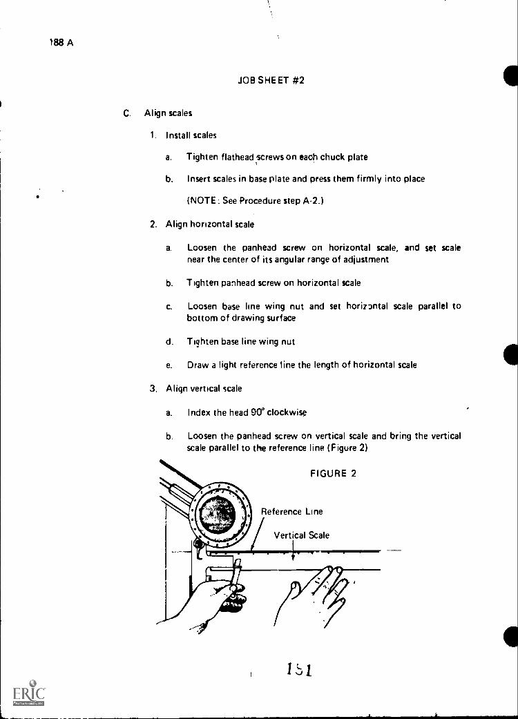
188 A
JOB SHEET #2
C. Align scales
1. Install scales
a. Tighten flathead screws on each chuck plate
b. Insert scales in base plate and press them firmly into place
(NOTE: See Procedure step A-2.)
2. Align horizontal scale
a. Loosen the panhead screw on horizontal scale, and set scalenear the center of its angular range of adjustment
b. Tighten panhead screw on horizontal scale
c. Loosen base line wing nut and set horiz3ntal scale parallel tobottom of drawing surface
d. Tighten base line wing nut
e. Draw a light reference line the length of horizontal scale
3. Align vertical scale
a. Index the head 900 clockwise
b. Loosen the panhead screw on vertical scale and bring the verticalscale parallel to the reference line (Figure 2)
FIGURE 2
Reference Line
Vertical Scale

a
MAJOR EQUIPMENTUNIT IV
NAME
TEST
1 Match the terms on the ,ight to the correct definnons
a. At a 90- angle to a (oven plane or line
b Any surface such as a drafting hoard ordesk used to Secure drawing media
c. Two lines or surfaces side by side, eyia;distances apart at all points
d. An edge used as a point of reference, such asthe edge of a drawing board or T square
e Parallel to the plane of the horizon
f, Any type of drawing material upon whichan object is graphically represented
g A line straight up and down, perpendicu-lar to the horizontal plane
h A measuring device consisting of a smallermain fixed scale and a smaller graduated scalethat slides to obtain brie measurements.
A foreshortened circle with a major andminor diameter
1 Horizontal
2 Vertical
3. Drawing media
4. Working surface
5. Perpendicular
6 Parallel
7. Working edge
8 Ellipse
9 Vernier
D 1 191 A
2 Identify the barts of a parallel bar hy Hal,1101 the correct numbi-r- to the ktft of itscorresponding narhe
a Bar
b Cable pulleys
c Cable clamp
ij Tension bracket
e Cdtlie
vor

192 A
-,t t ,hr f.: ljvdntars of a pdrallel bar.
b
c.
4. Describe the operation of a parallel bar.
5 Describe the use of an adjustable triangle.
6. Identify the parts of an elbow drafting machine by placing the correct number tothe .eft of its corresponding name.
e
a Elbow brake 1. Veptier plate
....
h Upper arm 1. Chuck plate
c. Clamp k. Protractor brake wing nut
led. Horizontal scale I. Index thumbpiece
e. Vertical scale rn. Base line wing nut
f Protractor _n Handle
q,
Adjusting screw o Standard protractor hi ao
Scale c huck p Lower arm- -10
g

7. List four advantages of an elbow drafting machine.
a.
b.
C.
d.
D I 193-A
ill
8. Describe the operation of an elbow drafting machine.
9. Identify the parts of a V-track drafting machine by placing the correct number to theleft of its corresponding name.
a. Horizontal motion brake 1. Vertical motion brake
b. Handle k. Chuck plate
c. Scale chuck I. Base line wing nut
d. Mounting clamp m. Protractor brake wing nut
e. Horizontal track n. Vernier plate
f. Vertical track o. Protractor
q. Standard protractor head p. Index thumbpiece
h. Vertical scale q. Baseplate
i. Horizontal scale r. Protractor head pivot point
s. Adjusting screw
19
5
1(;-,3
1817
11
13
15
7

194 A
10. List four advantages of a V-track drafting machine.
a.
b.
C.
d.
11. Describe how a V-track drafting machine operates.
12 Select rules to reitiember concerning -riaintenance and care of drafting machines byplacing an "X" in the approwiate blanks.
a. Keep scales alpgned and tight
b. Scales can be used as straight edge for exacto knife
c. Scales do not need to be kept clean
d. fighten baseline and protractor wing nuts snugly but not too tight
e. Store drafting machine with scales over the edge of the drafting table out ofthe way
Lift and move drafting machine by the scales
_y. Pvt,artor heath are hard to adjust, force if necessary
h Keep nand tension adjusted properly
Keep cupport clamps loose when not in use
13 List four rules related to the use and maintenance of an electric erasing machine.
a
b.
C.
d.
1 I11)

14. List two factors that determine the type of electric eraser refill to use.
a.
b.
D I - 195-A
15. Select types of electric refills and their uses by placing an "X" in ,he blank by the refillused only to erase pencil marks.
a. Dark grey
b. White
c. Pink
d. Green soft
e. Pink soft
f. Standard red
_g. Nu-Red
h. Vinyl
16. Operate a parallel bar.
17. Operate an adjustable triangle.
18. Measure angles with the protractor and vernier scale on a drafting machine.
19. Demonstrate the ability to:'
a. Make adjustments to a V-track drafting machine to install and align scales.
b. Make adjustments to an elbow drafting machine to install and align scales.
(NOTE: If these activities have not been accomplished prior to the test, ask yourinstructor when they should be completed.)
1 (.. -1A. ...) l
,
4,

,.
2.
D I - 197-A
MAJOR EOUIPMENTUNIT IV
ANSWERS TO TEST
a. 50. 4 _
C. 6'cf. 7e. 1
f. 3 0.
9. 2h. 9i. 8
tt
a. 5 c. 2 e. 1
b. 3 d. 4
3. Any three of the following:
a. Easy to make long horizontal linesb. More accurate than a T-squarec. Very little maintenanced. Simple to operate
4. A parallel bar is a long flat bar similar to a T-square that has a hollow area in its middlethrough which cables pass. These cables work through a series of pulleys, and the endsare attached to a tension bracket. The cables allow the bar to move in a parallel Motionup and down the working surface
5. An adjustable triangle is used in combination witha T-square or parallel bar to lay outlines that are not at the standard 15° increment
6. Parts of an elbow drafting machinea. 13 f. 12b. 10 k. 4c. 9 I. 7
d. 8 m. 5
e. 1 1 n. 6f. 2 o. 16
.9. 1 p. 17h. 3i. 15
7. Any four of the following:
a. Increases drafting outputh. Requires fewer tools to operatec. Less expensive than parallel track machined. Can be aligned to any base linee. More accurate than separate protractor instrumentf. Can be operated from any side of the drawing desk
i4
t
s
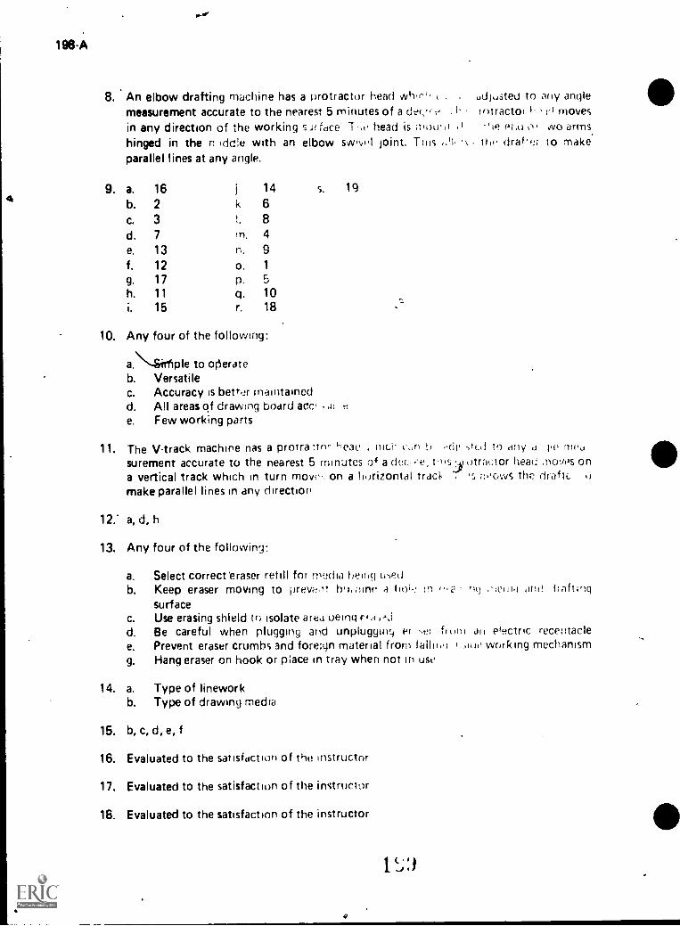
196-A
8. An elbow drafting machine has a firotractor head whIri,measurement accurate to the nearest 5 minutes of a der,-, t,in any direction of the working s,.11 face 7'.e head is mow ithinged in the n Idcfie with an elbow swiw.l joint. Thisparallel lines at any angle.
16
2
37
13
121711
15
14 S. 19
k 6!. 8rn. 4
n. 9o. 1
P.
q. 10r. 18
5
10. Any four of the followmg:
a.\-6ir1ple to oftrateb. VersatileC.
d.e.
Accuracy is better mallItainedAll areas (If drawIng board acc,Few working parts
udjusteu to any anglerotractor 1' ri moves
ii NM C I Wo armsliii draf,2;
11. The V-track machine nas a protra heac . t'S,r) Li de tid to artysurement accurate to the nearest 5 minutes of a dm. ins iotrat:tor head .novos ona vertical track which in turn move- on a horizontal tracIt i s a..owS the draftc.make parallel lines in any direction
to make.
d 1.E' filf'd
12." a, d, h
13. Any four of the followin9:
a.
b.
C.
d.e.
9.
14. a.
Select correct eraser refill for media heihri LhedKeep eraser moving to prev-t,lt nn.,linr. a hoi.: n ,..o '1(3 or 1 1,i arid iraftingsurfaceUse erasing shield to isolate area tieing F #.1Be careful when plugging and unplugginc it .er from an efectric recentaclePrevent eraser crumbs and fore:gn material from tallimi I ,1(11' working mechanismHang eraser on hook or pace in tray when not in use
Type of lineworkb. Type of drawing media
15. b, c, d, e, f
16. Evaluated to the satisfaction of the instructor
17. Evaluated to the satisfaction o f the i nstrucl or
18. Evaluated to the satisfaction of the instructor
1

0 I - 199-A
APPLYING FOR A JOBUNIT V
UNIT OBJECTIVE
After completion of this unit, the student should be able to locate a job opening, make aformal application, and effectively interview for a job. This knowledge will be tdenced bycorrectly performing the procedures outlined on the assignment sheets and by scoring 85
percent on the unit test.
SPECIFIC OBJECTIVES
After completion of this unit, the student should be able to:
1. Match terms aisociated with applying for a job with the correct definitions.
2. Select means of locating job openings.
3. List three methods of applying for a job..
4. Select personal attributes or attitudes an employer looks for during a personal
interview. C li
5. Select six items which an applicant may need to prepare when applying for ajob.
6. Select guidelines to follow when participating in a job interview.
7. Write a resume.
8. Write a letter of application for a drafting job.
9. Complete an effiployment application form for a job as a drafter.
10. Prepare a personal portfolio.
11. Practice interview questions.
12. Make an appointment by phone for a drafting job interview..,,..
13. Write a follow-up letter or make a follow-up phone call after interviewing for adrafting job:4
14. Evaluate a drafting job offer.
15. Compare job opportunities.
g

D I 201-A
APPLYING FOR A JOBUNIT V
SUGGESTED ACTIVITIES
I. Provide student with objective sheet.
Pronde student with information and assignment sheets.
III. Make transparencies.
I V. Discuss unit and specific objectives.
V. Discuss information and assignment sheets.
VI. Invite an Industry personnel manager to discuss "What to look for on applica-tion letters, resumes, employment application forms, and follow-up devices" and"How do equal opportunity and affirmative action affect my hiring procedures?"
VI I Obtain actual letters of application and resumes, both good and bad examples,and discuss each with students.
VIII. Use a panel of employers to talk about things they look for in a prospectiveemployee.
IX. Use video tape to record student practice interviews.
(NOTE: Although not as effective, an audio tape recorder can also be used.)
X. Have students critique their taped interviews.
XI Give test
INSTRUCTIONAL MATERIALS
A. Objective sheet
B Information sheet
C. Transparency masters
1. TM 1--Attitudes
2. TM 2--Appropriate Dreis
3. TM 3--Take Time to be on Time
/s).' A
AS,3 i',ment sneets
1. A ,ignment Sheet .4'-; 1 Write a Resumu
2 Assignment Sheet #2 -Write a Le;.ter of A,ji);.t n
Joh
3. Assignment Shect -43 Complete Esstp!ujoner,tJob as a Drafter
4
4. Assignment Sheet #4--Prepare a Per,,o,.al Po.'
5, Assignment Sheet #5 Practice Inter .ew nue
6. Assignment Sheet #6--Make an Appointment by Prione f.21 i uratonr
Job Interview
7 Assignment Sheet #1 I;e Eiplovy up , Make
Phone Call after IntenAewing for a DraitimJ Ii
8 Assignment Sheet #e, Fvaluate a Prhfo Ii- 5.
9 Assignment Sheet #0- Compare Joh .1t,e
Test
Ansv,t to test
1)nit -eler; nces
,
.edge, Eloci Fl tHrlt!,
our Job. Dal!es South li,estetrt
Ppol M How to cio .1 Job. Sho ritVocational Tecunical /
t",ov ohio, Moynihan, and ,ideut t''hl -1
Chicago .1 G. Ferguson Poblishirqj Conman,
Merle W and 1\4( Megarei., B CornuAnyo 1) IV1,05)11, IfY
-sci° 'so nut
t"I''t Me-W3( t. 'I
in.,, I. fl `,;(: r
Wolpfell JU!I Ii 145t Way ,,,Intiss'n;t, 19 74
(4.,1 Artirode is .3,
ieAds, 1972
Alien, Cliff "A i t Getttn t J jb" ord "At,fe. 'OA àflflIflL L
,oI. "''
It-

4
D I 203-A
J. Kimbrell, Grady, and Vineyard, Ben S. Succeeding in the World of Work.Bloomington, IL: McKnight eublishing Company, 1975.
K. Feingold, S. Norman, and Swerdloff, Sol. Occupations and Careers. St.Louis: McGraw-Hill Book Company/Webster Division, 1969.
Ir
,

. D I 205-A
APPLYING FOR A JOBUNIT V
INFORMATION SHEET
I Terms and definitions
A. Award Recognition received for outstanding achievement
B Extracurricular activities--Clubs, organizations, and social or church groups
in which one participates
Examples- VICA, AIDD
C. Fringe benefits--Extras provided by an employer, such as paid vacations, sick
leave, and insurance protection
D. Oualifications-Experience, education, and physical characteristics which suit
a person to a job
E Resume -Brief, typed summary of one's qualifications and experiencethat.is used in applying for a job
F Vocational preparation- Any vocational courses and skills one has learned in
school or through work experience
G Interview Meeting of employer and job applicant for pui pose of evalua-tion and questioning
H. Application form- Printed form on which job applicants record imormationabout their personal history, job history, job experience, education, and
references
I Blind ad Classified advertising that does not identify the advertiser
(NOTE: Applicant is asked to send a letter of application and resume to a
post office box number or to call a certain number.)
J. Help wanted ad-Classified advertisement telling what kind of job is available
and what the qualifications are
K Employment/situation wanted ad- Classified advertisement pli:ced by in-dividuals seeking employment and telling what their qualifications are
L Employment agency -Business that is designed to help individuals find em-
ployment
M. Portfolio A (Young-1g of samples of an individual's work
N Legible-Capable of being read; clear

206 A
INFORMATION SHEET
0 Equal opportunity employer-rmployet who is making a special effort ioassure that no form of discrimination is practiced
Fxampli;s: Age, sex, race, creed
II. Mewls of locating job openings
Classif ied ads
1. Newspapers
2. Magazines
B. Employment offices
I. State and federal labor offices
2. Private
(NOTE A fee is charged by most private agencies.)
C. Local labor union business office
D. School officials
1. Teacher
2. Counselor
3. Principal
4. Placement officer
E. Current worler.s in the drafting field
I; Methods of applying for a job
A Letter
d Telephone
In person
IV Perconal attributes or attitudes an employer looks for during a personal inter-view (Transparency I)
A. Enthusiasm and interest
(NOTE: This includes taking pride in your work and being willing to domore than your share when needed.)
"

D I - 207-A
INFORMATION SHEET
B. Dedication and dependability
(NOTE; This involves good work habits which include regular attendanceand being on time. It also means you should readily follow directions.)
C. Alertness, quickness of mind
(NOTE: You should always look for unsafe shuations that could injure'workers or damage property, and you should constantly look for moreefficient working practices.$ ,
D. Honesty and integrity
(NOTE: Employees should give truthful information both to customersand to their employer.)
c.
E. Desire to work
F. Ability to work with others
G. Desire to improve one's self
(NOTE: Good employees always look for ways to increase their know-ledge; this benefits both the employer and employee.)
V. Items which applicant may need to prepare when applying for a job (Assign-ment Sheets #1, #2, #3 and #6)
A. Resume
B. Letter of application
C. Applicatim form
D. Aptitude test
E. Portfolio
F. Follow up letter
VI. Guidelines to follow when participating in a job interview (Transparencies 2 and3)
A. Preparing for the interview
1. Wear appropriate clothing and shoes
(NOTE: Dress better for the interview than you would for a day onthe job. This includes well coordinated clothing and avoid the wearingof sneakers, sandals, or hats.)
\
4

208-A
B.
INFORMATION SHEET
2. t3t. tm_11croomed and neat
(NOTE: For a woman, this means neat Itair and anoworia,t, iewelry, for a man, neatly trimmed hair and beard, .1 ho wea,s one.)
3. Take an ink pen, several copies o4 your resume. and all ,nlo:rnat4onconcerning social security number, references. names and widreAsel,dates employed, and dates you attended school
4. rio alone, do not take parents or friends
5. Do not be late
(NOTE: Allow adequate time to complete a job application form I
6. Find out facts about the interviewer ahead of time
(NOTE: Obtain this information from the receptionist )
a. Nome
(NOTE: Make sute you hie.e the correct pronunciaticr
b. Tale
7. Know facts about the business
a. Name
b. Kind of business
Products and services
d How olt4 tfr company ts and where the plants, offtec. Itmesare located
(NOTE: This information may be h-trd to obtain Be r,tnerv:n waiting room. Ask receptionist for brochure on c)mpany !
Mewl() the receptionist/secretary
1 Smile
2 introduce yourself, stattnq thtif hay' an aoluid.tro
"tlooct mtirrtin9. 1 aq, rerr, 1. I
ire) 'or jc.t) Graf tor I hoVi, It) 00 ^
rni.:0% t,4CeiniOn;St'S :r1S1rilrtione
Vv.iit olfieNly
1 Owto'

e
D I 209-A
INFORMATION SHEET
C. Starting the interview
1. Smile
2. Listen carefully
3. Enter with poise
4. Greet the interviewer by name
5. Shake hands firmly
6. Introduce yourself
7. State purpose of call
8. Be seated only at interviewer's invitation
9. Do not show signs of nervousness
(NOTE: If you do not know where to put your hands, leave them onyourlap and keep them sthl.)
10. Do not place personal things on intervieweet desk
11. Do not smoke or chew gum
12. Look alert; look interested and enthusiastic
(NOTE: Words such as Mr., Mrs., Miss, Ms., thank you, please, andsir never go out of style.)
D. Answering questions clearly
1. Do not interrupt'
2. Anticipate questions that might be asked and volunteer proper infor-mation
a. Explain yes and no answers
b. Avoid criticisms of former employers or competitors
c. Do not talk about personal problems
d. Show copies of your work if applicable
(NOTE: Never go on a drafting job interview without takingseveral drawings. Good lettering should appear on application.)
1 '3

210
INFORMATION SHEET
Answer all questions honestly
Examples: "The, thing I liked least about my last was
that I was. on the night shift and couldn't getchanged. I really- Nanted to be home with myfamily at night.'
"Truthfully, my relationship with my supervisorcould have been better. We seemed to nave a per-son4jity conflict and never became fond of eachother. However,. we did manage to work together.This was my first experience like that and I surelyhope it doesn't happen again."
f. Give positive answers tiR unfavorable questions
E xamples: Interviewer: "Your work expenence doesn'tseem to relate specificallSr to thisjob. Why do you feel qualified tofill this position?"
Applicant. "I understand Our cbncern. How-.ever, my lob eiperienee is nroadenough to permit me to vvzs.-k intothis particular setuaticn. I Nave
done wort, similar to thi: joh Fndthink my general work ret,urd is
good enough to convince you that Iwould he a good employe' . I would
willuij to receive auditionaltra,ninc4
F4ind a true, positive sta tement :thoot your reasons I or iech IflCj
previous jobs, even if you were fit ed
Examplei: "I was laid off, iiiit I ;ear ro:d from iy mistakes "
"I left because ihr, rnany employees during the slow season "
h. Try to mention your best relatino sPridt him]
concrete
Example: "1 earned 75 rdertA,n' of my e),poses whilt, goingto school" is better ;him "I 0' .1 .4( '-vorker
want to get ahead."
1 s t

v!.
1341- 211,A
INFORMATION SHEET
i. Be prepared for personal questions about your home life andparents' occupations
I.
(NOTE: These questions are inappropriate but are sometimesasked by the interviewer.)
Avoid questions concerning politics, economics, religion, andother controversial subjects
k. Antwer questions about career objectives using specific termsabout what you would like to do in the near future in that parti-cular field without limiting your opportunities.
Example: "I would like to work as a mechanical drafter andgo to school part time;my ultimate goal is tobecome a mechanical engineer."
3. Look directly at interviewer
4. Speak in clear, moderate tones
5. Use correct English
(NOIE: Avoid rwearing, slang terms, or annoying phrases lik"you know," or "uhhuh.")
6.' Show interest in the business; ask questions
11
Example: Ihcorrect: "Listen, I need to know if you have anybenefits."
Incorrect: "Now that you've questioned me, thereare a few things that I want to knowbefore I decide if I want to work foryou."
Correct: "I wonder if you could give me someinformation about the benefits availableto employees?" .
7. Sell yourself
(NOTE: Never refer to yourself as just average or fair. Always look fora positive response.)
8. Give the interviewer the opportunity to mention salary and fringebenefits
9. Act enthusiastically

212.A
INFVRMATION SHEET
E. Closing the interview
1. Watch for signs that the interview is over. such as the inlet viewershuffling papers and moving around in chair
2. Ask "May I say one thing more?" or "Would you be inte,estei in...rid the interview seems to be ending before all important sellingpoints have been made
3. Thank interviewer for his/her time
E xample: "I've enjoyed talking to you. Mr. Smith. Thank you foryour time and consideration. I'm excited about thisjob and do hope I'm hired. Can you tell me when theposition will be filled and how the applicants will benotified? (Answer) Please let me know if you nek anyadditional information."
4. Learn from every situation even if the interviewei does not offerthe position
IMP
F. Following up the interview--Write thank you letter, call, or visit again toexpress interest in the job and appreciation foi the opportunity to interview
tIf

*
Attitudes
oc
Enthusiasm, Interest, Dedication, Dependability, Alertness,
Quickness of Mind, Honesty, Integrity, Desire to Work,
Desire to Help Others, Desire to Improve One's Self
, w
0-1116I n.)
C 2 1 ) 3 ia...1 III 09 >
4,..,..,

,
Appropriate Dress
v
..
Hair neatly trimmed and Combed ?
Well-Groomed ?
Conservative and CoordinatedClothing ?
Shoes in Good Repair ?
a
\
.. ,.-
1
2' )

Take the Time to be on Time
...
12
11

D I 719-A
APPLYING FOR A JOBUNIT V
ASSIGNMENT SHEET #1--WRITE A RESUME
Write a resume using accurate facts about yourself, Use the information below and thesample resume included in this assignment sheet as guides. A good resume should imme-diately give prospective employers a brief summary of your accomplishments, educationalbackground, work experience, skills, and job objective. It ifnot necessary to use the exactwording and outline form used on the sample resume, but it is necessary that your resumebe neat and balanced and contain all the information which might help you get a job. Keepa current copy of the resume and use it to apply for jobs.
1. Inspect several resume formats and choose one that best fits your needs or use theexample included in this assignment sheet as a guide
2. Type your resume on 8 1/2 x 11 inch white paper. Try not to exceed two pages.
3. Keep resume error free.
(NOTE: Many employer . will not consider persons who have resumes that includemisspelled words and typographical errors.)
4. Use outline form.
5. Put your name prominently at the top in the upper left-hand corner. Beneathname, give full street address, city, state, zip code, telephone number witn areacode, and a number where messages can be accepted.
(NOTE: Leave space at upper right for a wallet size photo.)
t Under Personal Data include birthdate, height, weight, health, and marital status.Do not include religious and political affiliations,
7. Describe your job objective or career goal briefly.
8. Descnbe your educational background, giving names of schools, dates of enroll-ment, and diploma or degrees received.
9. List related subjects studied. Include grade averages, if favorable.
10. List student activities and awards.
11. List hobbies and extracurricular activities, if they are relevant.
12, List your past employment, starting with your most recent job. Include name offirm, mailing address, job title, starting and ending dates of employment, name ofimmediate supervilor; and phone number.

220 A
ASSIGNMENT SHEET #1
13. List doties of your last job.
(NOT E. Concentrate on skills you have used. Let employer know what you cando. Remember, you have to prove your valu- to the business, especially if youhave little expeience.)
14 List three persons as character references. Include complete mailing addresses andphone numbers.
(NOTE Ask permission before you use anyone as a reference.)
.2. List one or mora jobs or work references, include people that you have actuallyworked for
(NOTE: Avoid listing relatives as a reference unless you have actual!y worked forthem on a salary basis.)
16 Write "Confidential" at the top of the resume if you don't want your currentemployer to know you are looking for other employment.
17. Proofread your resume carefully and retype if necessary. Reproduce severalcopies on white bond paper
(NOTE. Your resume's physical appearance is VERY IMPORTANT. Avoid using
ditto or carbon copies. Be sure to proofread the printer's work. Always bringextra copies to interview. Leave one copy of resume with interviewer and use oneas a reference when filling out the application form. You should also mail oneresume with your letter of application.)
/

ASSIGNMENT SHEET #1SMPLE RESUME
RESUMETERRY McKRACKFN
ADDRESS:
Present. 774 E. Adams Street Permanent: Route #3YourTown, YourState 77704 Anytown, YourState 77704(405) 311-7779 (405) 235-4433
PERSONAL DATA
Age: 18Birthdate: Jan. 21, 1963Height: 5' 7"Weight: 160 lbs.
JOB OBJECTIVE:
Mechanical Drafter
ULTIMATE GOAL:
Mechanical Engineer
EDUCATION:
Anytown High School, Anytown, YourState
Health: ExcellentMarital Status: SingleSocial Security Number: 447.37-0652
1977-81
Progress Vo-Tech, Progressville, YourState 1981Certificate: Drafting, Four SemestersGrade Average: 3.5 on a 4.0 scale
RELATED SUBJECTS STUDIED:
HO School
Algebra 2 semestersGeometry 1 semesterBasic Mechaniul Drawing 1 semesterTechnical Report Writing 1 semester
STUDENT ACTIVITIES
+.,
Vo-Tech School
Machine DraftingArchitectural thaftingPiping LayoutStructural DetailingDescriptive GeometryRelated MathematicsTrigonometry
President, Senior ClassPresident, VICATreasurer, Baptist Youth Fellowship OrganizationDrafting contest, Second Place State, Fifth Place National
-540 hrs.-270 hrs.-135 hrs.-135 hrs.
30 hrs.60 hrs.30 hrs.
D I 221-A
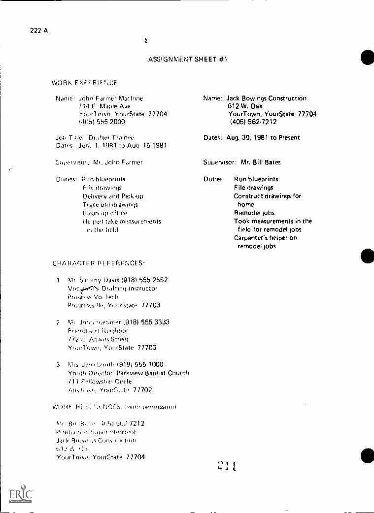
222 A
ASSIGNMENT SHEET #1
WORK EXPFR%CE
Nam. John Farmer M;chine114 E Maple AveYour Town, Your State 77704005) 555 2000
Joh Titk.- Drafter TraineeDates Juni 1, 1981 to Aug 15,1981
..e.ucer visor, Mr. John Farmer
Duties. Ron blueprintsF. III, (IraVVINS
Delivery and Pick-upTrace old ifrahingsCloan op officeticped take measurements
in the field
CHARACTER PLFERFNCES
1 Mr Siiiimy Davis (918) 555 2552Vocttierri'll Drafting InstructorProgress Vo I f,chProgressviile. YourState 77703
MI J9tin 'rammer t918) 555 3333Friond 'in.! Neighbor7/2 E Ariains StreetYtUfTOVVP, YourState 77703
3 Mrs Jerri 1918) 555 1000Youth Dirtic.tor Parkview Baptist Church/11 fellowshin Circle
YourSt ito 77702
WORk i. rr $ sviih permission)
1311, '41;'')) ',-)61 7212Pt,olt.c.,,(,,, ',mot -torviontJack Btl,t.y; Coris ructionc,1 2 ,".
YourTom,, YourState 77704
Name: Jack Bowings Construction612 W. OakYourTown, YourState 77704(405) 5627212
Dates: Aug. 30, 1981 to Present
Supervisor: Mr. Bill Bates
Duties- Run blueprintsFile drawingsConstruct drawings for
homeRemodel jobsTook measurements in the
firld for remodel jobsCarpenter's helper onremodel jobs

D I 223-A
APPLYING FOR A JOBUNIT V
ASSIGNMENT SHEET #2--WRITE A LETTER OFAPPLICATION FOR A DRAFTING JOB
The application letter is a sales technique to tell the employer how your abilities wilt beuseful to the business. The letter should specify your qualifications while the resume gives
general background information.
Cut a help-wanted ad for a drafting ob from the classified ad section of the local paper.Write an application letter to accompany the resume you prepared in Assignment Sheet #1.Use the following information ard the sample letter as a guide.
(NOTE: If you cannot type, q is recommended that you locate someone to type yourletters for you. Make sure you have a good typewriter available.)
1. Use acceptable form and appearance
a. Type neatly and accurately
b. Write on only one side of the paper
c. Avoid smudges and typographical errors
d. Use 8 1/2" x 11" white bond paper
(NOTE: Do not use personal or fancy paper.)
e. Spell, capitalize, and punctuate correctly
f. Include employer's full name, title, and address
g. Include your full name and address with zip code on the letter
h. Retain a copy for further reference
2. Include proper information
a. Write to a specific person
(NOTE: Find out the name of the personnel manager'employer you want toreach and the correct title. When in doubt, write to the top person who willrefer your resume to the right party. Use TO WHOM IT MAY CONCERN ifanswering a blind ad.)
b. Avoid excessive use of the pronoun "I"
c. Be brief; do not repeat information in the resume
1) State the position for which you are applying
2) Avoid needless details
rl 9am A ...,
224 A
ASSIGNMENT SHEET #2
3) Cover 311 points requested in the advertisement in exactly the orderin which they were asked
(NOTE: Some prospective employers make it a point of testing theapplicant's ability to follow directions )
d State reason for interest in job
(NOTE: Employers look for people who look for future advancementopportunities rather than just a paycheck.)
e. Refer briefly to the main points in the attached resume
f. Mention that persons listed on the resume have given their permissionto serve as references
g. Request interview at employer's convenience
1 Tell where you can he reached
2: Enclose self addressed envelope and resume
3) Say you will phone next week
3 Be original in your approach--Attract attention in opening paragraph
Examples
Dear Mr. Money:
My experience as a drafter would be of interest to you,
Dear Ms. Owner
Mr Co worker informed me that you are in need of a person who can be a draftertrainee. I believe that my experience and training have taught me how to handlethese duties efficiently and accurately.
4. End the letter properly
(NOTE: Sincerely yours or Very truly yours is appropriate.)
5. Use permanent address for the return address and make sure to include thecurrent date
6. Staple letter to resume as it may be circulated to several departments an-1 other-wise become detached

D I 225-A
ASSIGNMENT SHEET #2
6
7. Follow up and phone for an appointment a week later
(NOTE: Don't be surprised if the resume has been referred to another depart-ment. Remember, they are in business and you may not get immediate atten-tion, especially if you sent a blind letter. Be persistent until you reach the rightperson and ask for a convenient date to set up an interview.)
8. Keep in touch regarding possible openings now and in the future
(NOTE: The "iob hunt" may take several weeks or even months! It's importantto keep your contacts alive without being a nuisance.)
N

226-A
ASSIGNMENT SHEET #2
SAMPLE LETTER OF APPLICATION
Route #3Anytown, Yourstate 77702June 15, 1982
Mr. John JonesPersonnel Director8 & H DesignersYourtown, Yourstate 77704
Dear Mr. Jones:
Please consider me for the drafting job that you advertised in the Daily Chronicle.
The skills I have learned in my vocational drafting courses should qualify me for this job. Ihave had experience in all of the basic skills required by the drafting trade, including thesafe use of surveying instruments.
I will graduate from technical school in May, and I would like to become a drafter. A morecomplete description of my qualifications is given in the enclosed resume.
I would appreciate the opportunity to comeAnd talk over this job opportunity at ypurconvenience. I can be reached by telephone al 405-235-4433 fter 3:30 or at the atioveaddress.
Sincerely yours,
Terry MoKrackenEncl
IP^

r
I 227A
APPLYING FOR A JOBUNIT V
ASSIGNMENT SHEET #3-.COMPLETE EMPLOYMENT APPLICATIONFORM FOR A JOB AS A DRAFTER
Complete the following application form using the guidelines below. Use informationcorresponding to the classified ad and to your letter of application. Use information about
..yourself from your resume.
(NOTE: Although each business uses its own form, general rules of preparation applyto any form.)
1. Be prepared
a. Take a good ink pen with you
b. Take copies of resume
2. Look over entire form before starting to write, do not hurry
3. Follow directions
a. Note whether information is to be printed or handwritten
(NOTE: Many drafting firms have drafting applicants letter an applicationso it can be evaluated-)
b. Complete all directir;iis
4. Write or print clearly, neatly, and legibly
5. Answer briefly
6. Be honest
7. Answer all questions
(NOTE: If qu ntions do not apply to you, write Not Applicable or NA in thespace to show that you did not overlook the question.)
B. Include complete information, use resume
9. Recheck application when finished
10. Avoid cross-outs and obvious erasure marks
11. Do not list any restrictions to the geographical area in which you would workunless you absolutely will not consider other geographical areas
12. Use the word "open" for questions about minimum salary since most employerspay standardized rates and will not negotiate on this
13. Make copy of application, if possible

vD I 229-A
APPLYING FOR A JOBUNIT V
ASSIGNMENT SAET #4-PREPARE A PERSONAL PORTFOLIO
Aportfolio is a group ot samples of a person's work. Such work is then made available, to a prospective employer at the time of an interview so that he/she can see examples
of the quality work that you do.It
Prepare your personal portfolio for use in a job application. Be sure to remember thefollowing:
1. Select a wide variety of work
(NOTE: A job may require many different kinds of skills. A wide variety ofsamples will help the employer to see that you are qualified to do more thanjust one job.)
2. Select samples of your best work
(NOTE: To use samples of less than quality work would defeat the purpose ofthe portfolio. Show only samples of good work.)
3. Place your identification on all pieces included in the portfolio
(NOTE: An employer may choose to compare th4 work of various prospectiveemployees.)
4. Place all samples in some type of a case or covering
(NOTE: This is essential to protect the samples while being moved to new loca-tions. Be sure o put your name on the outside.)
0 1 ....4. k I

D I - 231-A
APPLYING FOR,A JOBUNIT V
ASSIGN ME NT SHE ET #5--PR ACTI CE I NTE RV I EW QUESTIONS
The following are some additional questions which might .be asked when applying forvarious jobs. 1<eep the assignment sheet to review before going on any actual interview.
)(NOTE: Quest' ns about yam personal life may not legally be asked. In fact, it is illegal foran employer t ask your maiden name or your father's surname if you a;e a female appli-cant; your ma *tal status; who lives with you; the church you attend or the name of yourspiritual leader; how many children you have, their ages, or who will care for them whileyou are at work; whether yoU own or rent yoUr residence; whether you have ever had your
wages garnished; and.whether you have ever been arrested. However, many interviewers,particularly in smaller businesses, may ask such questions. Whether or not you choosetoanswer the questions depends on how much you want the job.)
How would you answer the following questions? Why do you think each question might beasked?
1. Where do you go to school? When will you graduate?
2. Do you (did you) earn any of your own expense money while in school?
3. Why did you leave your pr/vious job(s)?
4. What did you like best and what did you like least about your classes?
(NOTE: This could be asked about teachers, jobs, or employers.)
5. What books have your read lately? What are your favorite magazines?
6. Are you in good health?
7. What do you expect to be doing five or ten years from now? What is your chosenttfield of work?
8. At what salary do you expect to start?
9. What are some of your special abilities? What skills do you possess? What tools orequipment can you operate?
10. How would you rate your training for this job? Very good? Fair?
11. What persona( characteristics do you think are needed to succeed in your voca-tion? A
C) I .
A A j

732- A
,
I
ASSIGNMENT SHEET #5
12. In what area do you need the most improvement?SN
13. Do you hke to work with other people or do you work best alone?
14. Do you have any questions you want to ask us?
15 Do you think your extracurricular activities were worth the time'you devotedto them?
16. How could you contribute to our organization? Why should we hire you?
t 17. Tell us about your family and any plans for marriage or further education.
(NOTE: REMEMBER: Legally, you do not hay.. to answer this question. How-ever, it is a good idea to prepare an answer in case such a question is asked.)
Examp:es: "My family includes a younger sister and my parents, with whom Ilive. My plans for marriage are undecided at this time, and I'mhoping that the experience gained by being an employee of yourcompany will help me to decide about furthering my education."
rather than
"Quite frankly, I regard this information as personal and choosenot to answer."
18. For what other jobs have you applied?
19. Do you have any military obligations to fulfill?
20. Give us an example of a project.,you finished under pressure.
21. May we write or call your last employer?
'2. How many people have you supervised at work or through organizations ofwhich you are a member?
L. How ctp you feel about the progress you have made salary-wise?
24. Would you be able to work all day Saturday and Sunday?
25. If you could start whool (or work) over again what would you do different-ly?
26. What is your school attendance record?
27. Have you done the best school work of which you are capable?
ill4*1. ti

D I 233-A
ASSIGNMf NT SHEET.:5----,
28. Do you require attention? Does criticism (listed) you?
(NOTE These- questrons are usually asked in a more subtle and indirect way )
29. What motivates you?
30. Would you be willing to relocate?
31. What size city do you prefer?
32. Have you saved any money?
33. Define cooperation.
34. What job with our company would you choose if you were entirely free to (Jo
so?
35. How do you feel about working overtime?
REMEMBER: YOU NEVER GFT A SECOND CHANCE TO MAKE A GOOD FIRSTIMPRESSIONn! GETTING A JOB IS A jOB1II
1
I ) . 1 1
Pl...."./
..

D I 235-A
APPLYING FOR A JOBUNIT V
ASSIGNMENT SHEET #13--MAKE AN APPOINTMENT BY PHONEFOR A DRAFTING JOB INTERVIEW
Making an appointment by phone does two things. First, it shows that you are interes-ted in saving :he employer's time. Second, it shows that Ni o u are thoughtful for asking whatwould be the Lest 1ime for you to see the employer.
1. Steps in making an appointment by phone
a. Plan what you are going to say before you call
b. State your name and reason for calling
Example: "Hello, this is Terry McKracken. I'm calling about your adin last night's paper for a drafter. May I have an appointmentfor an interview?"
c. Ask when would be the best time for you to come for the interview
d. Record the day, time, and place of the interview
e. Thank the receptionist for the help
2. Things to remember when calling for an appointment
a. Keep the receptionist on your side; the receptionist is there to help you
(NOTE: The receptionist is sometimes asked to evaluate the applicant.)
b. Do not ask ove'r the phone how much the job pays
(NOTE: Some questions about the nature of the job may be appropriate.)
C. Be polite and courteous
(NOTE: Remember that this call is the first contact you may have withthe firm. Make that first impression a good one.)
d. Ask if you should pick up an application blank or if they would like to sendit to you before the interview
Now that you have read about the correct way to arange for a lob interview, role play asituation where you make an appointment y phone. Use the checklist on the next page toevaluate your performance.

a
a
I
f
1
236-A
ASSIGNMENT SHEET #6
Was prepared before calling
Did not have to stammer to find the rightwords
Identified self immediately
Stated reasons for calling immediately
Asked the best time for an appoiniment withemployer
Was courteous and friendly
Asked about picking up application blank orhaving apphcation blank sent prior to inter-view
Thanked the receptionist
Made record of the interview date, hour, andplace
\
YES NO
I'
1
0 I 1"0.... a,. ,..:

D I - 237-A
APPLYING FOR A JOBUNIT V
ASSIGNMENT SHEET #7-WRITE A FOLLOW-UP LETTER OR MAKE AFOLLOW-UP PHONE CALL AFTER INTERVIEW FOR A DRAFTING JOB
It is sometimes hepful to return to a business an check again on possible job openings. Thisis often done about a week after the first interview. This short casual visit accomplishes twothings. It helps the interviewer remember you, and it shows that you haul a sincere interestin working for that company.
However, it is not always possible to have this type of informal atmo., ere when applyingfor a job. In which case, it is always proper to send a follow-up letter or make a follow-uptelephone call.
PART A
Write a follow-up letter thanking the employer for the interviw. Use any form you wish orfollow the format of the sample follow-up letter included in the assignment sheet.
1. Make sure your letter meets the following standards
a. Typed or written perfectly
b. Clean, nalt, and attractively arranged on the page
c. Free from spelling, punctuation, and grammatical errors
d. Sent within a day or two after the interview
? Include the following points in your follow-up letter
a. Expression of appreciat'an for interviewer's time and interest
b. Summary of your qualifications ind interest in position-
c. Your name, address, antl phone number (to make it easier for the employer tocontact you)
3. Make this last bid for the job a prime example of your excellent work habits; make theletter clean, neat, and well-worded
PART B
Role play a follow-up telephone call using the guidelines below.
1 Make sure you include the following information
a. Your name
b. Date of your interview
c. Position for which you were interviewed

238-A
ASSIGNMENT SHEET #7
2. Ask whether a decision has been made
Example: Incorrect: "Hello, Mr. Jones. This is Terry McKracken. You toldme you would let me know about the job, but I haven'theard anything from you. Why haven't you called me?"
Incorrect: "This is Terry McKracken. Did I get the job?"
Correct: "Hello, Mr. Jones. This is Terry Mckracken. I inter-viewed with you on June 30th for the position of adrafter. Have you made a decision on my applicationvet?"
3. If someone has, already been hired, thank the interviewer for considering you butexpress continued interest in working for the company
Example: Incorrect: "Oh well, that's my luck. Thanks anyway."
Incorrect: "I didn't want to work for your company anyway."
Correct: "I am sorry I was not hired. Thank you for at leastconsidering my apphcation. I am still interested inworking for the company and would appreciate youkeeping my application on file."

ASSIGNMENT SHEET #7
SAMPLE FOLLOW-UP LETTER
Route #3Anytown, Yourstate 77702July 1, 1980
Mr. John JonesPersonnel DirectorB & H DesignersBox 19Yourtown, Yourstate 77704
Dear Mr. Jones:
D I - 239.A
Thank you for interviewing me for the job of drafter trainee with your company. I feelthat working for B & H Designers would be enjoyable and that I could do the generaldrafting work that the job requires. I hope that I will have the opportunity to prove myworth
The application form you gave me is enclosed.
I will be available for work May 15. You may call me a'. my horde after 3.30 p.m. Thenumber is 405-235-4433.
Sincerely yours,
Terry McKracken
Encl.
(NOTE Be sure to sign your letter.)

0 I 241-A
APPLYING FOR A JOBUNIT V
ASSIGNMENT SHEET #8--EVALUATE A DRAFTING JOB OFFER
Instead of saying "yes" or "no" on the spot to a lob offer, express your gratitude in a warm
arid friendly manner, and then ask if you may have time to consider the opportunity youhave been offered. Few reputable employers will deny you a reasonable time to be certain
before agreeing to take a job.
Avoid :jetting stuck with a job that's wrong for you by using the following checklist toevaluate the job offer.
THE JOB .
Do I clearly understand the nature of the work and is it what I want to do? Are myresponsibilities reflected in the job title?
If this isn't my dream job, can it be a stepping stone as I acquire the skilts and exper-
ience needed for advancement?
Is the background I'm building so narrow that I will have difficulty transferring it toanother employer?
Will I he able to make any decisions affecting my work? Do I care?
Il I need more training and will the company pay for it?
IA0.1 oyertitne be necessary or available?
Wil I be able to leave all thought of the jot) behind at day's end? If not, do I care?
hue to travel or relocate?
the Itrh permanent (..r temporary?
b,,manent, is there reasonable job security?
r11 es rim job require union membership?
DI! COMPANY
tho fit ru; Too large and heavy with rules for my personaley?
t`e firr, too small to offer room for advancement i)r- mot eS',ivv credenti,es for a
',Iture resume?

242 A
ASSIGNMENT SHEET #8
Does the firm have a healthy financial position and is it a growing organization'
Is there a high turnover of personnel, and if so, why?
Does the firm promote from within the ranks or turn to outsiders to fill supervisoryjobs?
Have I met the person who would be my immediate supervisor'
Does the supervisor seem like the sort of person with whom I could get along?
Do co-workers appear to be my kind of people?
Is the company's location convenient?
What is the firm's reputation for fair treatment of employees?
Is a written personnel statement available that covers vacations, sick leave, cause fordismissal, and so forth?
FINANCIAL REWARDS ...
Do the earnings meet my minimum needs? Are there automatic costof-living increases?
What is the method of payment salary, hourly wage?
Are raises based on merit, length of service, formal exams?
What fringe benefits are given health insurance, free parking, discount privileges, andothers?
WHEN TO SAY NO . . .Should you always turn down an offer that doesn't measure up?
That depends on several questions. How desperately do you need to earn money? Howcompetitive is the field you hope to enter, and would it be best to get your foot in the doorany way you can? How valuable is the experience you'll gain? There are times when it iswise to accept a lob w'lich is not perfect in your eyes.
On the other hand, it could be hest to refuse the offer.
Adiot,1 T'{' Li Sh.40. tip I May rJor Td lot,' C. V.A.( Wj 1 F delr 1977
I

D I 243-A
APPLYING FOR A JOBUNIT V
ASSIGNMENT SHEET #9--COMPARE JOB OPPORTUNITIES
When you are offered a job or are changing jobs there are many factors to weigh beforetaking the position. Some of these include:
1. What is your take-home pay?
2. What are the benefits which accompany the job?
3. How much will it cost to actually be at work each day?
4. Would the job be satisfying to you?
5. How would the job meet your needs and aspirations?
WHAT'S MY TAKE-HOME PAY?
Salaries and wages are often quoted by employers as gross earnings. Gross earnings are usedbecause tax deductions vary due to the number of dependents, the amount of earnings, andother information.
Optional benefits and deductions offered by an employer also differ. It is generally advisableto ask what programs are available for enrollment as these can affect the actual money youreceive on pay day.
() ,/6. ...., .".!
"F4

244 A
ASSIGNMENT SHEET *9
WHAT OTHER BENEFITS DO I GET FROM THIS JOB?
Some benefits associated with working are not always visible. Often some of these overlooked benefits are paid for in part by your employer. At the time of the interview or whenconsidering a position ask about:
Employer's contributions for your protection which may include:
1. Health insurance
2. Unemployment compensation
3. Clothing and safety garments
4 Medical facilities and health tests
5 Pensions
6 1 ravel insurance (covering mithaps when traveling on business)
7. Educational programs or reimbursement for courses related to job
8. Sick leave with pay
9. Paid vacations,and holidays
WHAT WILL IT COST TO WORK AT THIS JOB?
r
Frequentiv, we often overlook the costs which are associated with being employed. Itmay be of value to calculate estimated weekly expenses before you make a decision about ajob.
Estimate weekly expenses for:
Transportation (parking,bus fares) $
Lunches (or cost of foodeaten away fromhome, includingsoft drinks andcoffee) $
Clothing (includingcleaning) e
..)
Child care for workingparent S
Gifts for otheremployees
Special uniforms,materials, orequipment forjob $
Other $
TOTAL $
1 ) I .. . 1aw ..... . i

D I - 245-A
ASSIGNMENT SHEET *9
WHAT IS IMPORTANT TO ME IN A JOB?
Take-home pay and benefits may be only part of what you want from a job. Think throughother things you consider important in a job.
What are some of the most rewarding things you've felt about any job you've ever had?
1.
2.
3.
How might you rate these in order of what's important to you?
Job security (little chance you'll be released from the job)
Opportunity for advancement
Recognition for your work
Good wages
Opportunity to learn and use your ideas
Flexible working hours
Long vacations
Pleasant working conditions
Interesting work
Friendly co-workers
Travel
Other, such as
ARE YOU READY TO DECIDE????
Take all the information you have gathered and summarize it below and on the next page toreach a decision about whether you want the job or not.
1. Would the job be satisfying to you? Why/why not?

246 A
wO
ASSIGNMENT SHEET #9
2. What are the benefits which accompany the job?
3. How Much will it cost to actually be at work each day?
How would the job meet your needs and aspirations?
5. I estimate my take-home pay to be $
6. I estimau. my expenses related to working to be $
7 I would most enjoy rhe following about this job.
8. I estimate my job henefits to be worth $
i
5'

APPLYING FOR A JOBUNIT V
NAME
TEST
D I 247 A
1. Match the terms on the tight to the correct definitions
a Brief, typed summary of one's lluallheationsand experience that is used in applying for aton
b Extras provided by an employer, sui h ,.tpaid vacations, sick leave, and insuranceprotection
c Recognition received for outstanding achievement
d. Experience, education, and physical char
2
3.
4
5
6.
7
8.
9.
10.
11
12
1:3
14
15
Award
Intetvww
Extracutricularactivities
Fringe benefits
Applicationform
Qualifications
Resort w
Portfolio
Vocationalprepatot mu
F mplo irntagency
Equal op, Airtung yeifiployi"
Blind ad
Help v\idirtedad
Legibli
Employment situ
4
acteristics which suit a person to a jun
Any vocational courses and skills one haslearned in high school or through worextwnence
f. Clubs, orgamiations, aryl social or churchgroups in which one par t innate',
It A grouping of samples of an Indkilddal',work
h Meeting of employet anil joh add'HCant
for purpose of evaluation and dni",iloning
Printed foim on which job applii ants te«edinformation about the,' person i history, johhistory, job experience, foiticd , Id leteretices
13usiness that is designed to Lido in(lividualsfind enloloynient
Classified advertising that does 1101 Of citifythe advertiser
.1 Classified advertisement placedeeking empioyment Ind hi idnq Writ
qualif irations are
9416, t.1
atinn vs anut d dd

,.,
248 A
,
.}
In. Classified advertisement telling what kind of_
,ob is available and what the qualifications are
n. Capable of being read; clear
__o. Employer who is making a special effort
,o assure that no form of discriminationis practiced
2 Seiect meads of locating job openings by placing an "X" in the appropriate blanks.
a. School officials
b. Parents
c. Employment offices
d. Local labor union business office,
e. Waiting to be called
f . Classified ads
3. i iv three methods of applying for a job.
10
4. r3.'' ct nerso,'al attribptes or attitudes an employer looks for during a personal inter-, v placing an "X" in the appropriate blanks.
.1
I
a. Alertness, quickness of mind
b. Long wavy hair
c. Dedication and dependability
d thusiasm and interest .0/
e. New car
f. Honesty and integrity
_g. Desire to work
h *Beard
r" i. Flashy clothes74--
il 1
AMII. II if %
,

I. Desire to help others
k: Desire to improve one's self
I. Ability to work well with others
0 I 249 A
5. Select items which an applicant may need to prepare when applying for a job byplacing an "X" in the appropriate blanks.
a. Written critique of company
b. Letter of application
c. Birth certificate
d. Resume
e. Portfolio
f. Application form
g. Follow-up latter
6. Select guidelines to follow when participating in a job interview by placing an "X" inthe appropriate blanks.
a. Take parents or friends with you to job interview
b. Know facts about the business
c. Start the interview with a smile and greet the interviewer by name
d. Place personal things, such as coat, hat, or purse, on interviewer's desk
e. Criticize former employers or competitors when applicable
f. State that you are willing to start at the beginning salary
9. Answer all questions honestly
h. Ask questions about politics, economics, religion, and other' controverskilsubjects
1. Look directly at interviewer
I. Do not ask questions or show interest in the business
k. Don't bother to take a pencil or pen with you
I. Thank interviewer for his/her time
rn. Write thank you letter, call, or visit dqiiin to express intere.,f in th( j()11,indappreciation for the opportunity to interview
4) II,aa. ii,

im
250 A
7. Write a resume.
8. Write a letter of application for a drafting job.
9. Complete employment application form for a job as a drafter.
10. Prepare a personal portfolio.
11. Practice interview questions.
12. Make an appointment by phone for a drafter job interview.
13. Write a follow-up letter or make a follow-up phone call after interviewing for a drafterjob.
14. Evaluate a drafting job offer.
15. Compare job opportunities.
(NOTE: If these activities have not been accomplished prior to the test, ask yourinstructor when they should be completed.)
,.

APPLYING FOR A JOBUNIT V
ANSWE RS TO TEST
1. a.
b.c.
d.e.
f.
9.h.
7
41
69382
i.
j.k.I.
m.n.
o.
5101215131411
2. a, c, d, f
3. a. Letterb. TelephoneC. In person
4. a, c, d, f, g, j, k, I
5. b, d, e, f, g
6. b, c, g, i, k, I, m
7.-15. Evaluated to the satisfaction of the instructor
fl 'bre1(... a .0 % )

D I - 1-B
MEDIAUNIT I
UNIT OBJECTIVE
After completion of this unit, the student should be able to relate media to its compositionand uses, list standard sheet and roll sizes, and demonstrate the ability to determine the feltside of vellum. This knowledge will be evidenced by correctly performing the proceduresoutlined in the job sheet and by scoring 85 percent on the unit test.
SPECIFIC OBJECTIVES
After completion of this unit, the student should be able to:
1. Match terms related to media with their correct definitions.
2. Match types of papers with their characteristics and uses.
3. Match types of papers with their compositions.
4. Describe two major problems with papers and their causes.
5. Match chalacteristics of paper surfaces with their correct definitions.
6. Match methods and characteristics of transparentizing with their correct defini-tions.
7. Select true statements concerning the composition and characteristics of tracingcloth.
8. Select true statements concerning the composition and characteristics of polyesterdrafting film.
9. Define scribe coat composition and scribe coat technique.
10. Complete a pie chart showing the distribution of costs for a drawing.
11. Classify standard media sheet sizes into the standard or alternate system by letterand dimension.
12. Arrange in order the suggested sequence for remembering standard media sheetsizes.
13. Complete a chart showing metric drawing sheet sizes and the nearest standardsizes.
14. List three basic widths and lengths of media roll sizes.
15. Select true statements concerning methods of determining the felt side of vellumwith and without watermarks.
16. Demonstrate the ability to determine the felt side of vellum without a watermark.

D I - 3-8
MEDIAUNIT I
SUGGESTED ACTIVITIES
I. Provide student with objective sheet.
II. Provide student with information and job sheets.
III. Make transparencies.
IV. Discuss unit and specific objectives.
V. Discuss information sheet.
VI. Discuss job sheet.
VII. Show students different types of media that might be used.
VIII. Show examples of different ways that various media are used.
IX. Invite a resource person from industry to relate to the students about the costsinvolved in drafting and how the dollar is divided.
X. Invite a vendor to bring samples of various media to class.
X I. Give test.
INSTRUCTIONAL MATERIALS
I Included in this unit
A. Objective sheet
B Information sheet
C. Transparency masters
1 TM #1 The Cost of a Drawing
2 TM #2 Sheet Sizes
D Job Sheet #1 -Determine the Felt Side of Vellum Without a Watermark
E. Test
F Answers to test
0'1 r;IL. 1 _J

4 Fi
W.PS
. nth, Waite! C Drafting for Industry. South Holldnii, IL 60473 TheI Willcox Company, Inc., 1974.
Joilo Thomas and Henry Cecil Spencer. Bas,c Technical Di-ail/myYork, NY 10022: Macmillan Publishing Co., Inc., 1968
Frederick E., et al. Technical Drawing. New York, NY 10022cr-l'an Puhlishinq Co., Inc., 1980.
Cecil and Jay Helsel. Engineering Drawing aril l)esiwl New YorkDiyision/McGraw Hill Book Company, 1979
3pPrice, P Drafting Technology and Practice Peoria, IL 61615-is Ai Bennett Co., Inc., 1973.
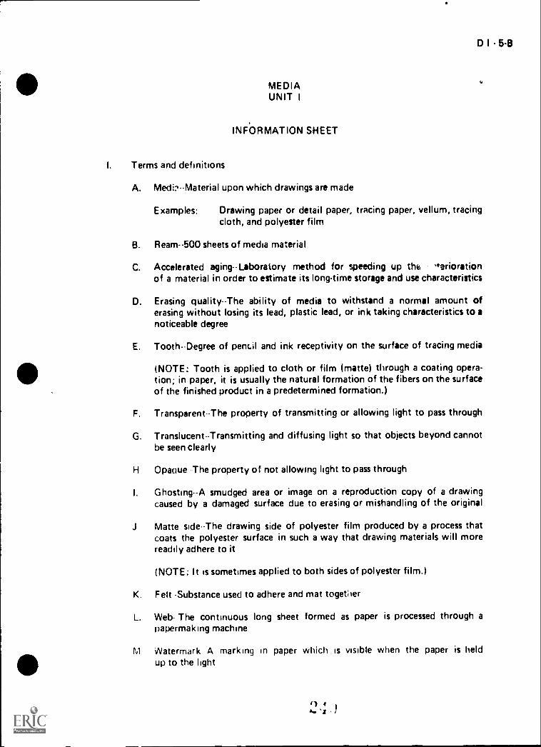
D I - 5-8
MEDIAUNIT I
INFORMATION SHEET
I. Terms and definitions
A. Medi?--Material upon which drawings are made
Examples: Drawing paper or detail paper, tracing paper, vellum, tracingcloth, and polyester film
B. Ream--500 sheets of media material
C. Accelerated aging-Laboratory method for speeding up the "adorationof a material in order to estimate its long-time storage and use characteristics
D. Erasing quality--The ability of media to withstand a normal amount oferasing without losing its lead, plastic lead, or ink taking characteristics to anoticeable degree
E. Tooth--Degree of pentd and ink receptivity on the surface of tracing media
(NOTE: Tooth is applied to cloth or film (matte) through a coating opera-tion; in paper, it is usually the natural formation of the fibers on the surfaceof the finished product in a predetermined formation.)
F. Transparent-The property of transmitting or allowing light to pass through
G. Translucent--Transmitting and diffusing light so that objects beyond cannotbe seen clearly
H Opaque The property of not allowing light to pass through
I. Ghosting--A smudged area or image on a reproduction copy of a drawingcaused by a damaged surface due to erasing or mishandling of the original
J Matte side-The drawing side of polyester film produced by a process thatcoats the polyester surface in such a way that drawing materials will morereadily adhere to it
(NOTE: It is sometimes applied to both sides of polyester film.)
K. Felt -Substance used to adhere and mat together
L. Web- The continuous long sheet formed as paper is processed through apapermaking machine
M Watermark A marking in paper which is visible when the paper is heldup to the light
tt) 4

6.8
INFORMATION Sill-
Tytics.,' papers their oar teristics, and ISeS
.1 40/1"9 p1),)1 A, heavy paper s,d,, used to, ,n1. work,'!1f,! !OUP Srde sed for pencit C,-,(111o: rivioduced nv blueprinting or similar processes
)(_.tsiii paper A heavy paper wh(P-e ade is used tor a.r. vt'or I , theUSW for pont t Aork, 1 Juno+, r". repruiluceu by blueptintinq
similar pi ocesses
C Tracing paper A th,n. untreated, ranikcelii oaper u'ted for ink ra pencilwork, it can he reproduced by t)11.1eprinIng or similar processes
(NOTE: Tracing paper and natural tracmit; pmaer ha.re qimiIar characteristicsand uses /
I) Vellum A ri ache) pallet that ildS heictl tr"ated .1 torospari.;ntizing .1.1C11t,
an be repioduced by blileprin'onn saraiar prof esse,
i I Ts pms tf plpers ..nd Moe compositions
Iv
',.-icipf;itt 100 percent Wv000 1)1,10 ISt ,orti ilita t,o r,r;
Rai, A clot,i anon? pript" flr'r,1 ' nig I, to ,,, ii(If wr
(N+OTE Pipe.r vlti 1CO, rOnrcnI , 111"-f 1,
!),lctiOt pro, 1,11)i lilt ,,11
A BeHy The r 0S,.1 "1,1; tht.' relirt,1 are ot (I
or web of ,fian:i,al osaai'y ao ,ahorot,o,l it mohoirehetv,een the center ahd the ed ;es if n- ;al
f-ri ripplt The raiplaii; ot the 1-41,,,e, of I 1,f 1, ItrrLi! 1.,; iiyby moistun, ihsoisition C'eatIng I0114 I III1US i Cent,uf Me material fails to expand an r
V Ch.o.tCtortt,CS of p iper ';urfaces and their
A T sided Ref-rence to the tart thal t ; `, 11,
IVOICh prndaros stY Lir-es ,APth dif f"rt:nr Jet ,is
ri oapelP, olt stile TI-,e side ot the p '1aperfiroaii`i a Paper inakinn machine
at; usual! ; pleierir, lo , l titt IN!
C \AJire side In., .,ide r, i !he paper 'ic r S , oy,11
th,ot1(111,1 pdOer tni1(1, n rriaefi,n,
(orE th,s svie usuaily presents tf'i r net,
41 4 Ii.

D I 7-8
INFORMATION SHEET
D. With the grain-The grain produced in the direction of flow as a sheet passesthrough a paper-making machine, (NOTE: It is usually along the length or longest dimension of the sheet.)
E. Cross grain-Across the width of a sheet
F. Closed formation--Formation of fibers in a sheet so that they give a uniform
appearance
G. Open formation-Formation of fibers in a sheet so that they give a mottledappearance
H. Mottled--Giving the appearance of uneven arrangement of fiber spacing
VI. Methods and characteristics of transparentizing and their definitions
A. Trarisparentizing-The treatment of paper or tracing cloth with oils, waxes,or resins to achieve a high degree of translucency
B. Solid transparentizer--A solid resin whose permanent nature will not leach or
lose its translucency
C. Mobile transparentizerA nonsolid resin, oil, or wax that will migrate and
usually leach on contact with any absorbent material
(NOTE: This is sometimes called a nonsohd transparentizer)
D. Nonhydroscopic transparentizer-A permanent, synthetic resin which makestracing paper water resistant and inhibits the tendency of media to curl
E Leaching--The tendency of a transparentizer to be removed from tracingpaper by migration from a media to another material
F Pin holes--Fiber ends that have become completely transparentized orparticles of man-made fibers that give tracing paper the appearance ofhaving tiny holes in it
VII. Composition and characteristics of tracing cloth
A. Made from a fabric that has undergone a transparentizing process
B. Usually made of a muslin fabric sized with a starch compound and plastic topro ,ide a good working surface for pencil or ink
(NOTE: Although sometimes referred to af. "linen," tracing cloth is actuallymade from cotton I
C. Tracing cloths made especially for pencil are available
E) 4 o)4., I ..

P. B
INF ORMATM SHEET
D 01.1' ',ult. of the ,,loth is used for drewing
E Itnportaiit dravvinus that must he stored for long rieriods of time are placedon tracing cloth because it is strong and durable and wiP Idst many yearslAuthout detertoiating
VIII Conioosition dnd iTharacteristics or 001/ester draft irN f
A UsudIly InaJe ny bonding a matte surfaca. to one or both sides ot 3 le4r
imiyester sheet to form a tough, transljefant orafting medium
B Rf2wts vei v. little to temperature or humidity changes necause of its dimen-sional stability
C Will retain stability even after much eras,' a;
D is aLriCAt impos,Ible to tear
Is mo,cture tes:siaot
D,; or nirtac side shoaii' be u-,en 1::.1.Pv:H9 +nen one side of to, titin haSa 7ndtte teush
oi r:;eaned vvit'- a moist ;hip( t- or lint free cic.th pricy t.) use
Poi sto, f1p SOIllctir1111:, 'Mylar, Which is re,iisteiedrrlftwiiark af
X r'LIC ;soda, t,Chrig,
j'0 :t ,F ade of I ado i r.o;) re,dted libe-glass c'ofl'i and asiwe: 10 tot nit material suitable for
ritairi
B tet.holque tisincj a scribe (stylusj to form lines into a scli)e coaiire ;Nt, ij f dravving them wi..h o' ink
OT[ rc scrib:ni, technical' ',,ith whtch reters toe ira;te soace of d
r,2tc,ota,i,tir
'1'}t'
1111 4..( r i, lc iuII crit,ts

D I 9-8
INFORMATION SHEET
X l. Letters and dimensions of standard media sheet sizes (Transparency 2)
A. Standard system
1. Size A--8 1/2" x 11"
2. Size B--11" x 17"
3. Size C--17" x 22"
4. Size D -22" x 34"
5. Size E--34" x 44"
(NOTE: Use of the standard sheet size of 8 1/2" x 11" and its multiplespermits filing in standard files.)
B. Alternate system
(NOTE: Use of the alternate sheet size of 9" x 12" and its multiples iscommon in the automobile industry because of the advantage of largerdrawing areas.)
1. Size A-9" x 12"
2. Size B--12" x 18"
3. Size C. 18" x 24"
4. Size D- 24" x 36"
5. Size E- 36" x 48"
(NOTE: Roll sizes are also classified, From small to large, these receivea designation of G, H, J, or K.)
XII Steps in remembering standard media sheet sizes
A Memorize the first size in each system
Example In the standard system, the first size is 8 1/2" x 11"; inthe alternate system, the first size is 9" x 12"
8 1/2 x 11 9 x 12
B The second number of each preceding sheet size becomes the first number ofeach succeeding sheet size
Example In the standard system, the 11" in the first sheet size be-comes the first number in the succeeding 11" x 17" size,and in the a!ternate system, the 12" in the first sheet sizebecomes the first number in the 12" x 18" size
11 x 17 12 x 18
4 q
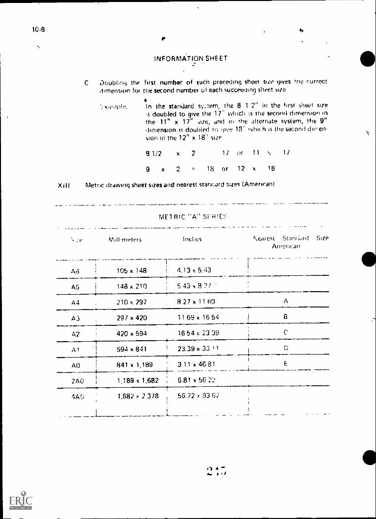
10-8
C Doubling thedimension for
INFORMATION SHEET
first number of each preceding sheet size gives the correctthe second number ot each soccer:row) sheet size
In the standard sy.tem, the 8 1'2" in the first sheet siteis doubled to give the 17" which is the second dimension inthe 11" x 17" size, dnd in the alternate system, the 9"dimension is doubled to 13" %vim h is the second deren-sion in me 12" x 18" size
8 1/2 x 2 1 / or 11 \ 1 /
9 x 2 - 18 or 12 x 18
XIII Metric drawing sheet sizes and nearest staricard sizes (American)
ME1 BIC "A" R
Ad
MIII.rneters
105 x 148 4.13 x 5.43
N.Cai est Stattf;orti SizeAlPerican
A5 148 x 210 5 43 x 8 21
A4 210 v. 297 8 27 x 11 h9 A
A3 291 x 420 11 69 x 16 54
A? 420 x 594 16 54 x 23 391
A 1 594 x 841 23.39 x 33 Ii4
AO 841 x 1,189 3 11 x 46 81
2A0 1,189 x 1,682 6.81 x 56 22
4A0 1,682 x 2,378 56.22 x 93 62
11 444.
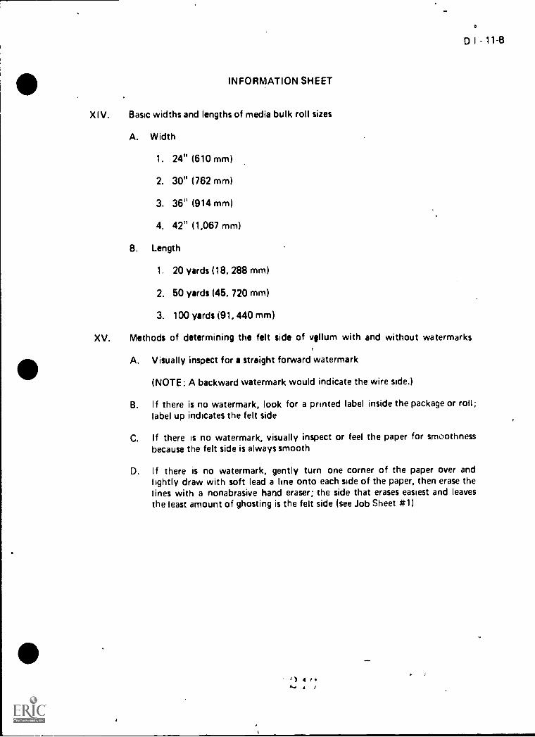
e
D I 11-B
0 INFORMATION SHEET
XIV. Basic widths and lengths of media bulk roll sizes
A. Width
1. 24" (610 mm)
2. 30" (762 mm)
3. 36" (914 mm)
4. 42" (1,067 mm)
B. Length
1. 20 yards (18, 288 mm)
2. 50 yards (45, 720 mm)
3. 100 yards (91, 440 mm)
XV. Methods of determining the felt side of vellum with and without watermarks
A. Visually inspect for a straight forward watermark
(NOTE: A backward watermark would indicate the wire side.)
B. If there is no watermark, look for a printed label inside the package or roll;label up indicates the felt side
C. If there is no watermark, visually inspect or feel the paper for smoothnessbecause the felt side is always smooth
D. If there is no watermark, gently turn one corner of the paper over andlightly draw with soft lead a line onto each side of the paper, then erase thelines with a nonabrasive hand eraser; the side that erases easiest and leavesthe least amount of ghosting is the felt side (see Job Sheet #1)
-4 1 4 e 0
L. 4 /

r
The Cost of a Drawing
CV I 13-B
RI$.65 Goes to Labor
. (Drafter Salaries) \
(51> (01
$.01 Goes for Tools $ Materials
4 TM I

.81/2x11 or 9 x12
7
A SIZE
c
B SIZE
C SIZE
i\li
Sheet Sizes
Round cornersoptional on all sizes
11x17
'for 12x18;
17x22 or 18x24
D SIZEMicrofilm alignment \___,arrowheads locatedmidway betweensheet edges on all4 sides E SIZE
-
1
r22x34 or 24x3 6
,
I,
Number BlockUpper Left
7
G
F
111,
-
/34 x 44 qr 36 x
1
4 5
iF
'..,Usuallyimaginary
Dlines forzone usage
c
Ar--
7 1 8
() 4S. '

D I - 17-B
MEDIAUNIT I
JOB SHEET #1--DETERMINE THE FELT SIDEOF VELLUM WITHOUT A WATERMARK
I. Tools and equipment
A. Sheet of vellum without a watermark
B. Nonabrasive hand eraser
C. Drawing pencil with soft lead
II. Procedure
A. Gently turn a corner of the vellum over until the backside forms a surfacewith the side that is up (Figure 1)
B. With soft lead, gently draw a line acrr.', ',1 paper at a point where thebackside and the up side intersect (Figure 2)
C Erase the lines, paying careful attention to which line erases the easiest andleaves the least amount of ghosting, this will be the felt side of the vellum

1
D I - 19-8
MEDIAUNIT I
NAME
TEST
1. Match the terms on the right with the correct definitions.
a. Material upon which drawings are made
b. A marking in paper which is visible whenthe paper is held up to the light
c. 500 sheets of media material
d. The continuous long sheet formed as paper ispncessed through a papermaking machine
e. Laboratory method for speeding up thedeterioration of a material in order to esti-mate its long-time storage and use charac-teristics
f,
9.
ft
Substance used to adhere and mat together
The ability of media to withstand a normalamount of erasing without losing its lead,plastic lead, or imit taking characteristics to anoticeable degree
The drawing side of polyester film produce:1by a process that coats the polyester surfacein sue, a way that draw ,nq (hi:aerialsmore radiiy adhere o it
Degree of pencil and ink receptiv,ty cnthe surface of tracing media
Th.r r;ror:ertv (if t' '",mttitu) f ()\Aring
it:;!it to paSs through
k Trdnynitting and hfobjects bevonii catmut ?so cledr:v
The property of not aro -cipg light to pass*J rough
pi A srpurirjed ,nt- in -riroductioncoo,/ co- ; t_ritlY2t ti
flc)r
lina
1. Transparent
2. Tooth
3. Erasing quality
4. Accelerated aging
5. Ream
6. Media
7. Translucent
8. Opaque
9. Ghosting
10. Matte side
11 Felt
12. Web
13. Watermark

r e types of pa,Ar on the right with the correct characteristics and uses.
a. A thin, untreated, translucent paper used forink or pencil work, it can be reproduced byblueprinting or similar process
1.
2.
b. A heavy paper whose smooth side is used 3.
for ink work, the rough side used for pencil 4.work; it cannot be reproduced by blue-printirg or similar processes
c. A tracing paper that has been treated with atransparentizing agent; it can be reproducedby blueprinting or similar processes
3. Match the types of paper on the right with their compositions.
Drawing paper
Detail paper
Tracing paper
Vellum
a. A cloth base paper containing various a- 1. Ragmounts of wood fiber
2. Sulphite1C0 percent wood pulp base stack paper;:ontaining no rag
4. Ddte two major problems with papers and their causes.
reify
r. Edge-ripple
tl'e caracteristics of paper surfaces on the right with their definitions.
Across the width of a sheet 1. Two sided
h The side of the paper which is up when 2. Felt side
the paper is processed through a paper-making machine
3. Wire side
4. With the grainc. Giving the appearance of uneven arrange-
ment of fiber spacing 5. Cross grain
d. Reference to the fact that all paper has 6. Closed formationa felt side and a wire side which producessurfaces with different qualities 7. Open formation
e. Formation of fibers in a sheet so that they 8. Mottled
give a mottled appearance
f. Formation of fibers in a sheet so that theygive a uniform appearance

g. The grain produced in the direction of flow asa sheet passes through a papermaking machine
h. The side of the paper which is down whenthe paper is processed through a papermaking machine
6. Match the methods and characteristics of transparentizngdefinitions.
a. The tendency of a transparentizer to beremoved from tracing paper by migrationfrom a media to another material
b. A solid resin whose permanent nature will notleach or lose its translucency
c. A nonsolid resin, oil, or wax that will migrateand usually leach on contact with any absor-bent material
d. The treatment of paper or tracing clothwith oils, waxes, or resins to achieve a highdegree of translucency
e Fiber ends that have be,.:ome completelytransparentized or particles of man madefibers that give tracing paper the appearanceof having tiny holes in it
f A permanent, synthetic resin which makestracing paper water resistant and inhibitsthe tendency of media to curl
DI-2141
on the right with their
1. Pin holes
2. Leaching
3. Nonhydroscopictransparentizer
4. Mobile transpar-entizer
5. Solid transparent.zer
6. Transparentizing
7 Select the true statements concerning the composition and characteristics of tracingcloth by placing an "X" in the appropriate blanks.
a. Tracing cloths made especially for pencil are available
b Made from a fabric that has not undergone a transparentizing process
c The shiny side of the cioih is used for drawing
d Usually made of a muslin fabric sized with a starch compound and plastic toprovide a good working surface for pencil or ink
Important fir-awl-1gs that must be stored for long periods of time are placedon tracing cloth because it is strong and durable and will last many yearswithout deteriorating

22-8
8. Select the true statements concerning the composition and characteristics of polyesterdrafting film by placing an "X" in the appropriate blanks.
d. Will retain stability even after much erasing
b. Is almost impossible to tear
c. Is not moisture resistant
O. Dull or matte side should be used for drawing when one side of the film hasa matte finish
e. Should be cleaned with a dry paper towel or lint-free cloth prior to use
f. Usually made by bonding a matte surface to one or both sides of a clearpolyester sheet to form a tough, translucent drafting medium
g. Reacts to temperature or humidity changes because of its dimensionalstability
9 Define scribe coat composition and scribe coat technique
10 Complete d pie chart showing the distribution of costs for a drawing.
11. Classify the foHoyon? standard media sheet sizes as either in the standard ot alternatesystem by placing a 'S" to the left of the standard and an "A" to the left of those inthe alternate system
Size A 9" x 12"
ti Size C 17" x 22"
Size E- 34" x 44"
ri Size B 12" x 18"
Size A 8 1/2" x 11"

f. Size D. 24" x 36"
g. Size D 22" x 34"
h. Size E 36" x 48"
i. Size Ek 1 1 " x 1 7"
j. Size C 18" x 24"
D I 23-8
12. Arrange in order the suggested sequence for remembering standard media sheet sizes byplacing a "1" to the left of the first step and proceed through the remaining steps.
a. The second number of each preceding sheet size becomes the first num-ber of each succeeding sheet size
b. Memorize the first size in each system
c. Doubling the first number of each preceding sheet size gives the correctdimension for the second number of each suceeding sheet size
13. Complete the following chart showing metric drawing sheet sizes and the nearest
standard sizes.
Metric "A" Series
Size Millimeters Inches Nearest Standard SizeAmerican
a 210 x 297 8.27 x 11.69 f,
b. 297 x 420 11.69 x 16.54 9.
420 x 594 16.54 x 23.39 h.
594 x 841 23.39 x 33.11
e. 841 x 1,189 33.11 x 46.81 I.
14. List three basic widths and lengths of media roll sizes.
a Widths
1)
2)
3)
tO .1

24 13
);
1... ,I, trHe statements concerning methods of determining the felt side of vellum.. r: nitootit watermarks by placing an "X" in the appropriate blanks.
a VisuMly inspect for a straight forward watermark
h if there is no watermark, visually inspect or feel the paper for smoothnessbecause the felt side is always smooth
c If there is no watermark, look for a printed label inside the package or roll;lnbel down indicates the felt side
1 ,-.r.: the ahility to determine the felt side of vellum without a watermark.
wiry has not been accomplished prior to the test, ask your instructorl)c, cornhleted )

SD I - 25-8
MEDIAUNIT I
ANSWERS TO TEST
1 a. 6 f. 11 k. 7
b. 13 9- 3 I. 8c. 5 h. 10 m. 9
d. 12 I. 2
e. 4 I. 1
2. a. 3
b. 1 and 2C. 4
3. a. 1
b. 2
4. Descriptions should include:
a. Belly-The bagging (loss of dimensional stability) near the center area of a sheetor web of material usually caused by an uneven absorpton of moisture betweenthe center and the edges of the material
..,
b. Edge-ripple--The rippling of the edges of a sheet of material usually caused bymoisture absorption creating expansion along the edges when the center of thematerial fails to expand an equal amount
5. a. 5 e. 7
b. 2 f. 6C. 8 9- 4d 1 h. 3
6 a. 2 d 6b. 5 e 1
c. 4 f. 3
7. a, d, e
8 a, b, d, f
9 Definition should include.
d Scribe coat is made of thin aluminum sheets, coated fiberglass cloth, and a heavyplastic sheet to form a dimensionally stable material suitable for scnbing
b Scribing is a technique using a scribe to form lines into a scribe coat surfaceinstead of drawing them with pencil or ink

26 8
10 a. One cent goes fnr tools and materials costsFive cents (Ines for reproduction costs
ri, ( env; 9( ws tor engineering costsrI Sixty five C ..fits goes for drafting cost,
11 ,1 A Ab. S q S
( S t A
rt. A 1 S
I. S ,\
12. .1
I) 1
1. 3
13 a Aa f Ab A.3 q B
c A2 li C
d A ) 1 U
tA AO E
14 Width; (dhy ()Iwe of the followirn.)
94"') Jo31 36"4) 42"
7() var.21 50 /aids"1 100 vaids
15
1 6 F. , I , sd t t, Ihni f II F. it t 1.1CtUr
,

,
D 1 - 27-B
LETTE R I NGUNIT 11
UNIT OBJECTIVE
After completiOn of this unit, the student should 'be able to list the reasons for "nestthe.proodure for forming letters, and the use of guidelines arldthe instruments for
making them. the strident should also be able tq relote paper size to proPer lettering height
imd draw both, lower-cue and upper-case vertical and inclined Gothic letters. This know-ledge wit be evidenced by correctly performing the procedures outlined on the usignmentsheets end by sOoring 115 percent oh the unit test.
SPECIFIC OBJECTIVES
After completiOn of this unit, the student should be able to:
1. Differentiate between condensed and extended letters.
2. Differentiate between boldface and lightface letters.
3. Select true statements concerning ..zions end rules for neat lettering.
4. List guidelines for litter selection.
5. Select true statements concernihg the procedure for forming letters.
6. Select true statements concerning the rules for left-handed drafters.
7. Select the purposes of guidelines.
B. Select true statements concerning rules for making guidelines.
9. List reasons for using Gothic single-stroke vertical anOnclined lettering.
10. Select basic rules for learning to letter.
11. Select true statements concerning rules for spacing.
12. Distinguish between suggested leads used for lettering and for constructingguidelines. .
13. List types of line guides used for laying out gdidelines for lettering.
14. Arrange in order the sugrted steps in using a Braddock Rowe triangle.
15. Arrange in order the suggested steps in using an Ames type lettering guide.4
own t.,17

.
.r
16. Match the name of lettering instruments with the correct description.
17. Select true statements concerning rules for different types of lettering.
18. Complete a chart showing recommended lettering height in relation to papersize. . '
19. Identify common prOblenX in lettering uniformity.,
20. Discuss common problems in lettering nobility.
21. Ditmonstrate,the abilitito:
Ia
:
,.
I -a. Select and sharpen feed correctly:. ..
b. Operate a Braddock Rowe triangle to construct guidelines.
c. Operate an Ames type lettering guide to construct guidelines.
d. Construct vertical Gothic lettering and numerals.
ie. Construct inclined Gothic lettering and numerals.
f. Construct vertical lowercase Gothic letiering.
g. Construct inclined lower-can Gothic lettering. ,
h. Prepare vertical and inclined lettering exercises.-2\\
Ill e4.. i, ()
4
\
,
1

'0
,
} .
,,,
LETTERINGUNIT II
*,
SUGGESTED ACTIVITIES '.i
I. Provide student with objective sheet.
II. Provide student with information anel assignment sheets.
III. Make transparencies. q,
IV. Discusltnit and specific objectives. 4
e
0
,
D I --29-8
V. Discuss information sheet...
VI. Discuss the procedures outlined in the assignment sheets., . .
VII. .Use filg drawings to demonstrate to the class examples of correct and incorrectlettering.
VIII. Show lettering templates that may be used in drafting..1
IX. Demonstrate the use of different types of lettering instruments.4
X. Demonstrate the use of the Braddock Rowe triangle, Ames type lettering guideand parallelograph. i
/,
X I. Give test. ;
INSTRUCTIONAL MATERIALS
I. Included in this unit:
A. Objective sheet
B. Information sheet
C. Transparency misters,
1. TM 1--Condensed and Extended Lettering4, / ,2. TM 2--Rules for Making Guidelines
3. TM 3--Steps in Using a Braddock Rowe Triangle
4. TM 4--Steps'in Using an Ames Type Lettering Guide
5. TM 5--Types of Lettering Instruments
6, TM 6--Types of Lettering Instruments (Continued)
2C I

30-8
7. TM Types of Lettering instruments (Continued)
8. TM 6 .let.ical Gothic Lettering
9. TM 9 inclined Gothic Lettering
10. TM 10--Vertical Gothic Lower-Case Lettering
11. TM 11--Inclined Gothic Lower-Case Lettering
12. TM 12-- Inclined Lettering Unitormity
13. TM 13- Vertical Lettering Uniformity
U. Assignment sheets
1. Assignment Sheet #1--Select and Sharpen Lead Correctly
2. Assignment Sheet #2 Operate a Braddock Rowe Triaegle to Construct Guidelines
3 Assignment Sheet' #3--Operate an Ames Type Lettering Guide toConstruct Guidelines
4. Assignment Sheet .44-Construct Vertical Gothic Lettering and Nu-merals
5. Assignment Sheet #5.-Construct Inclined Gothic Lettering and Nu-Me als
6. Assignineat Sheet #6- Construct Vertical Lower-Case Gothic Letter-ing
7. Assignment She% #7--Construct Inclined Lower-Case Gothic Letter-ing
8. Assignment Sheet 48-Prepare Vertical and Inclined Lettering Exercises
F. Test
F AnsIAL's
renctic,
A Brown, Walter C. Drafting for Inclutry. South Holland, IL 60473: The(ooart Willcu4 Company, inc., 1974.
)ygdon, John Inomds and Henry Cecil Spencer Basic Technical Drawing.New York NY 10022: Macmillan Publishing Co., Inc., 1968.
Of b.)gh. IL0

D I - 31-13
110 C. Giesecke, Frederick E., et al. Technical Drawing New York, NY 10022:Macmillan Publishing Co., Inc., 1980.
D. Jensen, Cecil and Jay Helsel. Engineering Drawing and Design. New York,NY: Gregg Division/McGraw-Hill Book Company, 1979.
E. Spence, William P. Wafting Technology and Practice. Peoria, IL 61615:Chas. A. Bennett Co.; Inc., 1973.
F. The American Society of Mechanical Engineers. Line Conventions andLettering. Nel/ York, NY, 10017, 1979.

D I - 33-B
LETTERINGUNIT II
INFORMATION SHEET..
I. Condensed and extended letters (Transparency 1)
A. Condensed--Letters that are narrower and spaced closer together thannormal
(NOTE: Condensed letters may sometimes be referred to as compressedletters.)
B. Extended--Letters that are wider than normal
II. Boldface and lightface letters (Transparency 1)
A. Boldface--Letters made up of heavy components
B. Lightface--Letters made up of thin components
III. Reasons and rules for neat lettering
410 A. Sill Se approximately 20% of a drafter's time is used in lettering, neat let-tering conserves time and money for the individual and the company
B. Lettering can greatly affect the oyerall appearance of a drawing
C. Most drawings are reproduced, therefore, the lettering must be done withneatness, accuracy, speed, legibility, and be a dense black
D. The letters must be formed very carefully and not crowded together orthey will run together When reproduced
E. When additions or revisions are made to a drawing, the original style oflettering should be matched
IV. Guidelines for letter selection
A. For machine drawings, upper case (capital) letters are used and may bevertiral or inclined
(NOTE: Vertical and inclined letters should never be mixed on the samedrawing.)
B. For topographic drawings or maps, lower case letters are used for notes
(NOTE: Vertical letters are a little mote legible than slant letters; however,they are more difficult to draw.)
I) I 4A-.. I) i

34
iNFORMAT1ON SHEET
V. ProGeduie f.2r pirninq lettels
A The yertii.11 or inclined sttokes of letters are usually tormed hy fingermovement
Tne horizontal stiokes of letters aro made by (i movement ot 1 mc handthe wrist alono Nat, a very slight fill.jer movement
C Ovak of the. Litters are formed hy a movement of the nand and tingersvigether
J. The forearm should he at a 90 #ngie to the Tea to he lettered, and rest onthe drawing board for all lettering movements
VI Roles for ieft-handed drafters
A The left hardnd drafter should follow a system of stt'okes that will involvepulhne the pen or pencil instead of pushing it
(rxrE. Pushing the pen or pencil tends to dig into tne paper.)
B Vert e- a: ,niti inclined strokes should be done from top to bottom
C. Muyement on horizontal strokes should be done from right to left
Vvhen lettering, a lefthandershruld normally take a position exactlythat of a right winder, the left-handers that letter with a hooked
have more dftiCuiLy and must adopt a system that seen s he;.t for theirt,r ular abits )
VII 1:wpos,:s
r.,,keet, :et ters exactly the :same heir,ht
-op iet icrs ,paccd pri,perly
C I I.tt I t:c!rs positioned in the same direction
T,-; toe o-trall 1 omnosition uf letter( d infia rnal,on
,
H( I
'1,
0"gneo ar;,-1 cut clIC C:1 oltn 'a,,e to .rfact
of,es shoi.:(i n did i f a .etrelin'i guide
H I e
e,
,
A...1)o)
t1`'

D I - 35-8
INFORMATION SHEET
IX. Reasons for using Gothic single-stroke vertical and inclined lettering
A. Saves time in production
B. Easy to read and provides drawing consistency
C. Students learn to use it faster
D. Cost of drawings is reduced
X. Basic rules for learning to letter
(NOTE When lettering, select a comfortable position either sitting or standing.)
A. Learn the shapes
B. Learn the strokes
C. Learn the rules of spacing
D. Learn to practice with a determination to improve
E. Master one letter at a time
X l . Rules ior spacing
A. Spacing between letters is determined by the area between two letters10.06" or 1.5 mm), not just the distance between two letters
B. The spacing of words is attained by using an imaginary letter "0" as aspacer
C. The spacing between two sentences is attained by using an imaginary doubleletter "00" as a spacer
D. The space between two numerals separated by a decimal point (4.1) shouldhe a minimum of 2/3 the height of the numerals
E. The space between lines of lettering should be a minimum of 1/2 the heightof the lettering and a maximum of the same height as the lettering
F. Notes must be placed horizontally on the drawing
(NOTE: To identify separate notes, at least double the height of the charac-ter is used.)
G. Use underline lettering only when special emphasis is needed
(NOTE: The underline should be a minimum of 0.06" (1.5mm) below thelettering.)

36-8 4
INFORMATION SHEET
H. The division line in a common fraction should be parallel to the direction thedimension reads and the numerator and denominator of a fraction should beseparated by a 0.06" (1.5mm) space
RIGHT WRONG
i -a
1_2
I 8A -6r-64
I. A diagonal line is permissible only when fractions are placed in lists, tables,or notes
J Each numeral in a fraction should be the same height as a whole number
XII. Suggested leads
A. Lettering
1. HB
2. F
3. H
4 2H
B. Constructing guidelines
1. 4H
2. 5H
3. 6H
1 r . +.4A.0 t..# /

0 I - 378
.INFORMATION SHEET
4. Non-reproducible blue
(NOTE: Guidelines should be light enough so that when a drawingis held at arms length they cannot be seen.)
XIII. Types of line guides used in laying out guidelines for lettering
A. Braddock Rowe triangle
B. Ames type lettering guide
C. Parallelograph
XIV. Steps in using a Braddock Rowe triangle (Transparency 3)
A. Align and secure paper to drawing surface with drafting tape on each corner
B. Place Braddock Rowe triangle against top' edge of drafting machine orparallel bar
C. Select letter height which is expressed in 1/32 (3/32 through 8/32)
D. Sharpen lead
E. Place pencil in appropriate tioles fqr height of letter required and movetriangle across horizontal blade
F. When lettering uppercase letters, omit the middle guideline which is used forlowercase letters
G. Construct guidelines vertically by using vertical blade or a triangle
H. Incline guidelines by using a 68 notch on the Braddock Rowe triangle
XV: Steps in using an Ames type lettering guide (Transparency 4)
A. Align and secure paper to drawing surface with drafting tape on each corner
B. Place Ames type lettering guide against top edge of drafting machine orparallel bar
C. Select appropriate letter height which is expressed in 1/32 and can beselected by rotation of the circular selector
D. Sharpen lead
E. Place lead in appropriate holes for height of letter required and move Amestype lettering guide across top edge of blade in a smooth, light motion
F. When lettering uppercase letters, omit the middle guideline which is used forlowercase letters
'1 I .,A..... o _J

38-3
INFORMATION SHEET
G Construct guidelines vertically by using vertical blade or triangle
H. Incline guidelines by using the 68" slope on the Ames type lettwing quide
XVI Description of lettering instruments
A. Leroy lettrmng instrumentAn instrument consisting of a template, a scriber,and an inking,pen (Transparency 5)
(NOTE A guide pin follows grooved letters in a template, and the inkpoint moves on the paper. Various sizes and styles of guides are available.)
B. Vangraph--A device for making a wide variety of either single stroke or"built-up" letters (Transparency 6)
(NOTE : Angle of letters, size, and height of letters can be changed byadjustments on the body of the scriber.)
C. LetterguideAn instrument much like the varigraph (but simpler) whichalso makes a large variety of styles and sizes oi letters (Transparency 6)
(NOTE: It also operates with a guide pin moving in the grooved lettersof the template while the per, which is mounted on the adjustabie arm,makes toe letters in outline.)
D Varityper -An instrument which uses a one time carbon ribbon and has anear standard typewnter keyboard with an Open ended carnage (Trans-parency 6)
(NOTE. This allows it to receive various size drawings i-fundreds of insr,inr I v changeable typefaces are available for the vantyper.)
F Terhizite A thin, flat sheet of plastic with letters cut through the sheet(Tr.irtr,narency 6)
(NOTE A pN I 1, inserted Into the ,irorive arid retx4ed back And tortlit,- limn the shdp at me letter. Spncing of inOlvitival Ielters rtitl.t be done
fl Thir A roach.ne that produc,s "Type on tape" ransparenc,i
(NO f F d blaLk letters Lorne out of a transparent tauk. that can heHet!): ) the r-op sdc._ of i urdiit,,n,4 Type di .t.s fot the rmichino
'sly ir,tere nar, ii lr em, in four p,.p.t;dt typ,: drbt e
trurr 8 to 3t.,

D I - 39-I3
INFORMATION SHEET
XVII. Rules concerning different types of lettering
A. Vertical Gothic (Transparency 8)
1. The number 1 end letter I have no width,
2. The width of the letter W is 1 1/3 times its height
3. Letters that are equal in height and width are A, M, 0, Ci, T, V, X, Y
4. All other letters not noted above have a width 5/6 their height
5. All numerals except the numeral one have a width 5/6 their height
6. If the center area of the following letters is placed at midheight of theline, it appears to be below center; therefore, these strokes are placedslightly above the center point of these letters: 13, E, F, and H
,7. When the heights vary on upper case letters, the small upper case
letters are to be 2/3 to 4/5 the height of the large upper case lettering
Example LETTERING8. Lettering is not writing but freehand drawing, and the six funds-, mental strokes of freehand drawing are used in lettering
Examples:
.
Vertical
Inclined
0
aB. Inclined Gothic (Transparency 9)-..
1. The same rules for letter sizes and spacing that apply in vertical let-tering apply in inclined lettering
2. Circular parts of letters should be made elliptical by having the majoraxis inclined at a 45 angle to the horizontal so they will appear to slantproperly to the ri Iht
.ffirrammorm=marffilY1110111

40.E1
,
4 ,,
INFORMATION SHEET
1
3 The letters A, V. W, X, and Y have sloping sides and are difficult tomake unless an imaginary inclined center line is used and the letter isdrawn symmetrically around it
(NOTE: This method is a good one for beginning drafters to prac-tice.)
C. Vertical Gothic lower-case (Transparency 10)
1. The shapes of vertical lower-case lettering are based on the circle,circular arc, and straight line
(NOTE: There are some variations.)
2. The third stroke of the e is shghtly above midheight of the letter
3. The horizontal strokes of the f and t are placed on the waist line, andare an equal distance frpm stroke number 1
4. On the letters h, m, n, and r, the curved strokes intersect the first strokeat roughly 2/3 the distance from the base line to the waist line
5. On the letters g, j, and y, the descenders form a curve tangent to thedrop line
6. The letters p and q terminate without curves on the drop line
7. When upper case and lower case letters are used, the lower case leitershould be 2/3 the height of the uppercase letter
(NOTE: An exception to this rule is lettering for microfilm.)
8. On lower-case letters, the ascending or descending stems are equal iniength to the height of the capitals
D. Inclined Gothic lower-case (Transparency I 1)
1 The same rules for letter sizes and spacing that apply in verti_caI lettenng apptv in inclined lettering
, 2. Circular parts of letters should be made elhptical by having the majoraxis inclined at a 45° angle to the horzontal so they;ivill appear to slantproperly to the right
3. The letters c, o, s, v, w, x, and z have the same form as their cor-responding capitals
fl " 1A . A.

D I - 41-B
1 INFORMATION SHEET
XVIII. Paper size and lettering standards
\ A. Paper size and letter height
tandard U.S. Metric Paper\ Paper Size Size
Recommended LetteringHeight
Millimeters Decimals Fractions(Inches) (1 nches)
A A4
,
3.2 0.125 1/8
El A3 3.2 0.125 1/8
C A2 4.0 0.156 5/32
D Al 4.8 0.188 3/16
E AO 4.8 0.188 3/16
(NOTE: The larger the drawing size the larger the lettering required.)
XIX. Common problems in-lettering uniformity (Transparencies 12 and 13)
A. Letters are not uniform in height
B. Letters are not inclined or vertically uniform
C. Letters are not uniform in stroke thickness
D. Areas are not tiniform between letters
E. Style of letters is not uniform
F. Areas are not uniform between words
XX. Common problems in lettering stability (Transparencies 12 and 13)
A. On some letters, if the top portion is the same width as the bottom, the.3,
letter, appear to be top heavy
B. If the center area of certain letters is placed at midheight to the line, itappears to be below center, therefore these strokes are placed slightly abovethe center point of the letters B, E, F, and H
ii. ...

Condensed and Extended
Lettering
CONDENSED LETTERS
EXTENDED LETTERS
Vertical
Condensed Letters
Extended LettersInclined
.,
1 BOLDFACE LIGHTFACE
Boldface and Lightface Letters-.,
2-;3
D I - 43-EI
TM 1

i!ules for Making GStep A
Step B Step CStep D
Step E

Step A
Steps in Using a
s" Braddock Rowe Triangle

o,,,,
Step B
,
Steps in Using an i .
Ames Type Lettering Guide4

Types of Lettering Instninentsop
Pen
Scriber
qo
Leroy Lettering Instrument
or
a_alCo

Types of Lettering histruments
.nglp Alphabet'.4NTS MEWL ALL
G SMALL
11LTACJIL" TILL
Any TyfrIES
b.
Varigraph, Italic Model Headwriter
Varigraph, Inc.
Courtesy Letterguide
17
VIERTIcALSghaVire ITALICS
AMERCED SOLIDS64MMM4115 SIOWAL
AuLvmm ONEturrnommno
C.
Letterguide
VariTyper Corporation
" mormmmwomm4mmimms- ,
cms
d.
Vari Typer Office ComposingMachine, Model 660
e.
Template

Types of Lettering Instruments
---
i
.
-1Nis
IMMIN"""8"...°°. 4
D I - 551-B
)
Lettering Machine
(NoteAvailable in either Manual or Electric )
41
2 S 3
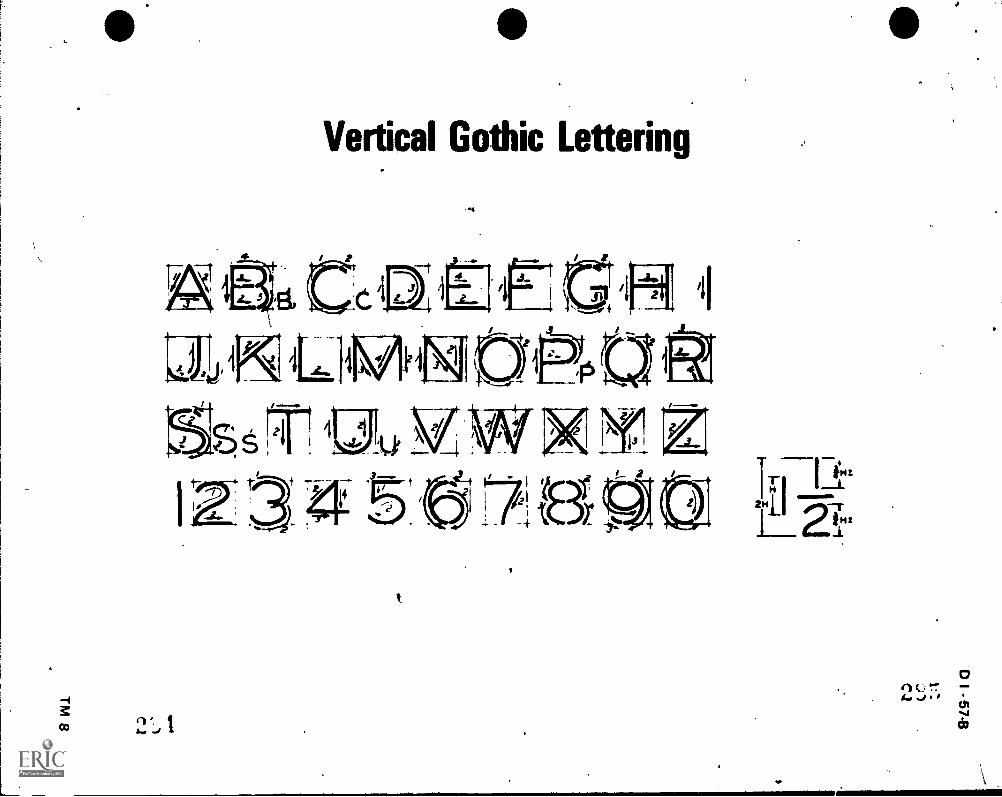
Vertical Gothic Lettering
,,,
4-N.,,,cliq

/
Inclined Gothic Lettering,
g

Vertical Gothic Lower Case Lettering
e
...a ...Mil....
4 II
-.4
--

LT 77,
o e
Inclined Gothic Lower Case Lettering

Inclined Lettering Uniformity
e
I.+
UNIFORM
UMFORM
UNIFORM
LIN IFO R M
UniFoRM
66000 LETTERINGSHOULOBE UMFOPM
UMFORM
rop HEAVY'LE r TERS
CORRECT.LE rrEps
D I 65 B
A LETTERS NOT UNIFORMIN HEIGHT
8 LETTERS ARE NOT UNIFORMLYINCLINED
C LETTERS NOT UMFORM INSTROKE THICKNESS
:
D AREAS ARE NOT UMFORMBETWEEN LETTERS
E STYLE OF LETTERS ISNOT UNIFORM
F AREAS ARE NOT UN/FORMBETWEEN WORDS
G UNIFORM LETTERING
Lettering Stability
c/ ciaqiE/oovH#/zo4
I Iwo,foigtt 4 i ' 1I.... t TM 12

/ D I 67-8
Vertical Lettering UnifonnityUNIFORM A LETTERS NOT UNIFORM
IN HEIGHT
UNIFORM B LET TERS ARE NOT VERTICALLYUNIFORM
UNIFORM
UN I FO R M
UniFoRM
IGOOD LE T TERINGSHOULDBE UNIFORM
C LETTERS NOT UNIFORM INSTROKE THICKNESS
D AREAS ARE NOT UNIFORMBETWEEN LETTERS
E STYLE OF LETTERS ISNOT UNIFORM
F AREAS ARE NOT UNIFORMBETWEEN WORDS
UNIFORM G UNIFORM LETTERING
TOP-HEAVYLETTERS
CORRECTLETTERS
Lettering Stability
S X21
1z
3 5
TM 13

D I 69-B
LETTERINGUNIT II
ASSIL 'MENT SHEET #1--SELECT AND SHARPEN LEAD CORRECTLY
Tools and equipment
A. Lead holder or pencil
B. Lead pointer
C. Drawing paper or media
D. Pencil pointer
E. Paper towel or cleaning cloth
F. Styrofoam point cleaner or tissue
II. Procedure
A. Select correct lead weight
B. Sharpen lead to correct point
C. After lead has been sharpened correctly, remove excessgraphite from pencilusing styrofoam point cleaner or tissue
(NOTE: This will preyent lead from smudging drawing.)
Pencil Lead Holder
IA.... , ;
;i

D I 71-B
LETTERINGUNIT II
ASSIGNMENT SHEET #2--OPERATE A BRADDOCK ROWE TRIANGLETO CONSTRUCT GUIDELINES
Tools and equipment
A. Braddock Rowe triangle
B. Drafting machine or parallel bar
C. Lead holder
D Drawing media
E. Drawing surface
I I Procedure (Transparency 3)
A. Align and secure paper to drawing surface with drafting tape on each corner
B. Place Braddock Rowe triangle against top edge of machine or bar
C Select letter height which is expressed in 1/32 (3/32 through 8/32 areindicated on the mangle)
D Sharpen lead
E. Place pencil in appropriate holes for height of letter required and movetriangle across horizontal blade
F. Omit the middle guideline which is used for lowercase letters when letteringuppercase letters
(NOTE: Guidehnes may be constructed vertically by using vertical blade ortriangle.)

Still A
,
tep 4
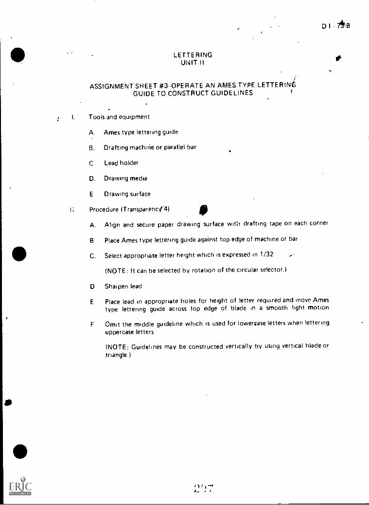
LETTERINGUNIT II
ASSIGNMENT SHEET #3 OPERATE AN AMES TYPE LETTERINGUIDE TO CONSTRUCT GUIDELINES
I. Tools and equipment
A. Ames type lettering guide
B. Drafting machine or parallel bar
C Lead holder
D. Drawing media
E Drawing surface
Procedure (TransparencNT4)
D I 7913
A. Align and secure paper drawing surface with drafting tape on each corner
8 Place Ames type lettering guide against top edge of machine or bar
C. Select appropriate letter height which is expressed in 1/32
(NOTE: It can be selected by rotation of the circular selector.)
D Shat pen lead
E Place lead in appropriate holes for height of letter required and move Amestype lettering guide across top edge of blade in a smooth light motion
F Omit the middle guidehne which is used for lowercase letters when letteringuppercase letters
(NOTE: Guidehnes may be constructed vertically by using vertical blade ortriangle.)
1)1.1.-4IL, 1

11
74 L3
4*
-
ASI(NMENI ;-)rif `. i
-,.
, ti, igho, r,f Ihi: procodlirc
Step B
N.
i
1

LETTERINGUNIT II
ASSIGNMENT SHEET #4CONSTRUCT VERTICAL GOTHICLETTERING AND NUMERALS
I Tool. and equipment
A Lead holder or pencil
B. Drafting tape
C. Drawing surface
D Scale or lettering guide
E Drafting machine or parallel bar
F Pencil pointer
11. Procedure (Transparency 8)
A. Secure lettering exercise paper to surface with tape
B Prepare point of lead for lettering4
C. Hold lead holder in correct position
D Study forms and strokes of letters and numerals shown in diagram
E Copy letters and numerals on guidelines
(NOTE: Use proper form anti stroke techniques.)
I I I Diagram of the procedure
A Obtain A size drawing media
./1
D I 75 8

76 B
ASSIGNA4NT SHEET #4
epai e point of lead
(NOTE. Point should de dulled clightly to dive ,jvsred width".of letterelements )
C. Use correct lead DOStQfl
(f\...)TE. Use an even pressure and rotate the lead in the fingers after everyfew suni. es to get uniforri line.,
D StLdv form of letters
TiacP over letters to learn strokes of eech letter ard numer )
4 le, , II
VWXYZ
1,1
u...) I
ro
D I - 77-8
0 ASSIGNMENT SHEET *4 \
,
_E. Construct guidelines
(NOTE: Space 1/4" apart and copy letters end numerals shown in step D.Use space below for lettering exercise.)
t.
I

t
.
-°°PLETTERING
UNIT II
ASSIGNMENT SHEET #5-CONSTRUCT INCLINED GOTHICLETTERING ANC NUMERALS
Tools and equipment
A. Lead holder or pencil
B. Drafting tape
C. Drawing surface
D. Scale or lettering guide
E. Drafting machine or parallel bar
F. Pencil pointer
II. Procedure (Transparency 9)
A. Secure lettering exercjse paper to drawing surface with tape
B. Prepare point of lead for lettering
C. Hold lead holder in correct position
D. ptUdy forms and strokes of letters and rumerals shown in diagram
E. Copy letters and numerals on guidelines
(NOTE: Use p;oper form and stroke techniques.)
III. Diagram of the procedure
A. Obtain A size drawing med:a
4 4o )....
-_rioll111111111
ill7
D I - 79-8

7jr
A 80 13
,
ASSIGNMENT SHEET '4 5
B. Prepare point of lead
(NOTE: Point should be dulled slightly to givp desired width of letterelements 1
C. Use correct nencil position
;NOTE Use an even pressure and rotate the lead in the fingers after everyfevv strokes to get uniform lines l
D. Study form of letthrs
_. .
(NOTE. Trace over letters to learn strokes of each letter and numeral.)
.
C D .L7,---:' F G. f-L--/ /j LM Al a P Q RST VVWXY &,,
1 ..: 3. .
\
44
1-------/ 'I4"
t ,; 4 1
.1_l''it
tl

0 l - 81-B
ASSIGNMENT SHEET #5
E. Construct guidelines
(NOTE: Space 1/4" apart and copy letters and numerals shown in step D.
Use space below for lettering exercise.)
o1 ,,
',..

D I - 83-B
iLETTERING
UNIT II
ASSIGNMENT SHEET #6--CONSTRUCT VERTICAL LOWERCASEGOTHIC LETTERING
I. Tools and equipment
A. Lead hi 1r or pencil
B. Drafting tape
C. Drawing surface
D. Scale or lettering guide
E. Drafting machine or parallel bar
F. Pencil pointer
II. Procedure (Transparency 10)
A. Secure lettering exercise paper to drawing surface with tape
B. Prepare point of lead for lettering
C. Hold lead holder in correct position
D. Study forms and strokes of letters and numerals shown in diagram
E. Copy letters and numerals on guidelines using proper form and stroketechniques
III. Diagram of the procedure
A. Obtain A size drawing media
1
_

84-8
ASSIGNMENT SHEET 6
B. Prepare point of lead
(NOTE. Point should be dulled siightIy to give desired width of letterelements )
C. Use correct pencil position
(NOTE: Use an even pressure and rotate the lead in the fingers after everyfew strokes to get uniform lines.)
D Study form of letters
/
..INOTE, Trace over letters to learn strokes of each ietter and numeral )
di: Occietf gib I;
Mlfiapc:r3I'LlivwX4 :4--....---------7
') , l .. ,

D 1 - 85-B
ASSIGNMENT SHEET *6
E. Construct guidelinti
(NOTE : Space 1/4" apart and copy letters and numerals shown in step D.Use space below for lettering exercise.)
i --.3,, ,
'r
lit
P

LETTERINGUNIT ll
ASSIGNMENT SHEET #7--CONSTRUCT INCLINED LOWER-CASEGOTHIC LETTERING
Tools and equipment
A. Lead holder or pencil
B. Drattin9 tape
i C. Drawing lurface
D. Scale or lettering guide
E. Drafting machine or parallel bar
F. Pencil pointer
II. Procedure (Transparency 11)
A. Secure lettering exercise paper to drawing surface with tape
B. Prepare point of lead for lettering
C. Hold lead holder in correct position
D. Study forms and strokes of letters and numerals shown in diagram
r
D I - 87-8
E. Copy letters and pumerals on guidelines using proper form and stroketechniques
III. Diagram of the procedure
A. Obtain A size drawing media

888
ASSIGNMENT SHEET #7
B. Prepare point of lead
(NOTE: Point should be dulled slightly to give desired width of letterelements.)
C. Use correct pencil position
(NOTE: Use an even pressure and rotate the lead in the fingers after everyfew strokes to get ,iniform lines I
D. Study form of letters
(NOTE: Trace over letters to learn strokes of each letter and numeral.)
ik /Ann q
pqrq wx

\ D 1 89-8
ASSIGNMENT SHEET #7
E. Construct guidelines
(NOTE: Space 1/4" apart and copy letters and numerals shown in step D.
Use space below for lettering exercise.)
,

0 I 91-B
LETTERINGUNIT II
ASSIGNMENT SHEET #8-PREPARE VERTICAL AND INCLINEDLETTERING EXERCISES
I. Tools and equipment
A. Lead holder or pencil
B. Drafting tape
C. Drawing surface
D. Scale or lettering guide
E. Drafting machine or parallel bar
F. Pencil pointer
II. Procedure
A. Complete vertical lettering exercise--uppercase
1. Secure A size drawing media to drawing surface and lay out sheetas shown in diagram
2. Use proper form and strokes to complete exercise of vertical letters andnumerals as assigned by instructor
3. Use A size media with 1/2" borders; use guidelines as shown
B. Complete inclined lettering exercise--uppercase
1. Secure A size drawing media to drawing surface and lay out sheetas shown in diagram
2. Use proper form and strokes to complete exercise of inclined lettersand numerals as assigned by instructor
3. Use A size media with 1/2" borders; use guidelines as shown
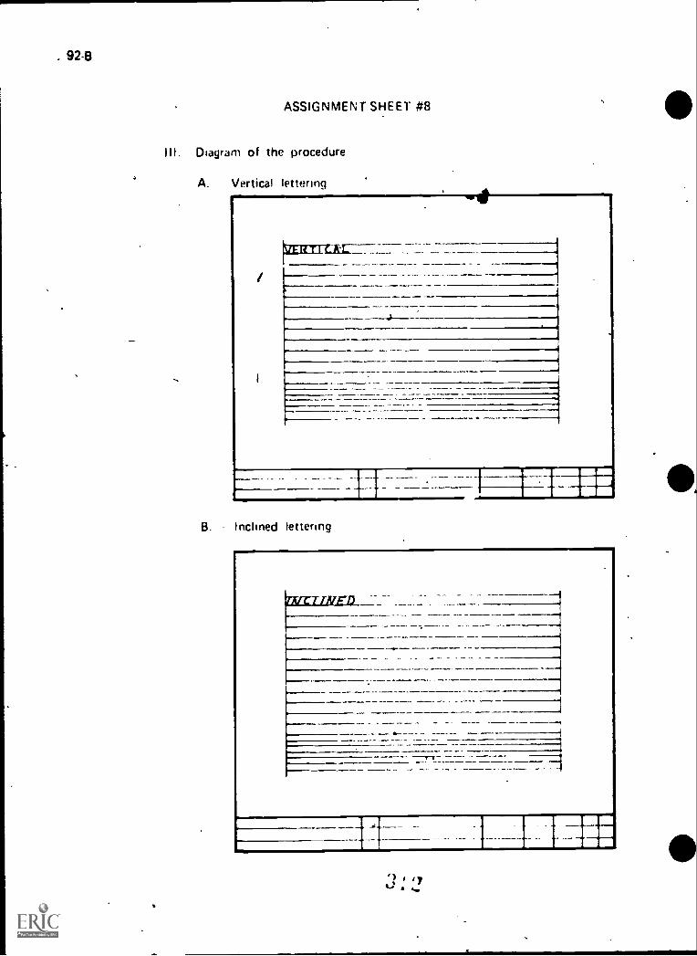
. 92-B
ASSIGNMENT SHEET #8
III. Diagram of the procedure
A. Vertical lettering
isannizkr_
B. Inclined lettering
941

i
/
t
LETTERINGUNIT II
NAME 4
TEST
D I 93-B
SD1. Differentiate between condensed and extended letterc by placing an "X" the left of
the description of extended letters.
a. Letters that are narrower and spaced closer together than normal
b. Letters that are wider than normal
2. Differentiate between boldface and lightface letters by placing an "X" to the left ofthe description of lightface letters.
a. Letters made up of thin components
b. Letters made up of heavy componentsPs
3. Select true statements concernin9 the reasons and rules for neat lettering by placing an
"X" in the appropriate blanks.
a. Since .approximately 60% of the drafter's time is used in lettering, both timeand money are saved by the individual or company
b. Lettering can greatly affect the overall appearance of a drawing
c. Although letters must he formed very carefully, skill should be used sto letter
as much as possible in a limited space
d. When additions or revisions are made to a drawing, the original style oflettering should be matched
e. Most .drawings are reproduced, therefore, the lettering must be done withneatness, accuracy, speed, legibility, and be a dense black
4. List two guidelines for letter selection.
a.
b.
5. Select true statements concerning the procedures for forming letters by placing an
in the appropriate blanks.
a. Ovals of the letters are formed by a movement of the hand and fingers
together
b. The forearm should be at a 90* angle to the area to be lettered, .ind rest on
the drawing board for all lettering movements
2 ' 1

94 8t
c The vertical or inclined strokes of letters are usually formed by finger andwrist movement
d. The horizontal strokes of lettering are made by a movement of the handat the wrist along with a very slight finger movement
6. Select true statements concerning rules for left-handed drafters by placing an "X" inthe appropriate blanks
a. Vertical and inclined strokes should be done from top to bottom
n. Movement on horizontal strokes should be done from left to right
c The left-handed drafter should follow a system of strokes that will involvepulling the pen or penctl instead of pushing it
7 Select from the following list the purposes of guidelines by placing an "X" in theappropriate blanks.
f.
a. To keep letters spaced properly
b To improve the overall composition of lettered information
c To keep letters exactly the same width
d. fo maintain correctness in drawing illustrations
e To keep letters exactly the same height
f. To keep letters positioned in the same direct:on
8. Select true statements concerning rules ior making guidelines by placing anin the appropriaze blanks.
a. Make vertical guidelines with the aid of a lettering guide
h Ahgn paper and secure corners with tape to working surface
c Horizontal guidelines should be accurately spaced
d Although guidelines are often useful, they are not necessary when a Brad-dock Rowe triangle is used
e Guidelines should not reproduce
9 List three reasons for using Gothic single stroke verbcal and inclined lettering
a.
b.
c.
"3( : 1

1
D I - 95-B
10. Select from the following list basic rules for learning to letter by placing an "X" in theappropriate blanks. .
a. Learn the strokes
b. Master groups of five letters at a time
c. Master one letter at a time
d. Learn the shapes
_e. Learn the rules of spacing
f. Learn the sizes
g. Learn to practice with a determination to improve
11. Select true statementi concerning rules for spacing by placing an "X" in the appro-priate blanks.
a. The spacing of words is attained by using an imaginary letter "0" as aspacer
, b. Notes must be placed vertically on the drawing
c. Use underline lettering only when special emphasis is needed
d, The division line in a common fraction should be parallel to the direction thedimension reads and the numerator and denominator of a fraction should beseparated by a 0.06" space .
e. The spacing between two sentences should always be 1/4"
f. Spacing between letters is determined by the area between- two letters,not just the distance between two letters
g. Each numeral in a fraction should be the same width as a whole number
12. Distinguish between tuggested leads for lettering and thpse used for constructingguidelines by placing an "X" to the left of those used in lettering.
a. Non-reprn-'.icible blue
b. H
c. 2H
d. 4H
e. 5H
f. 6H
g.
h,

96-84
13. Lkt three types of hrr guides used hr laying out guidelines for lettering.
a.
b.
14. Arrange in order the suggested steps in using a Braddock Rowe Mangle by placing a"1" to the left of the first step and continue through all steps.
a. Sharpen lead
b. tielect letter height which is expressed in 1/32
c. Align and secure paper to drawing su'rface with drafting tape on each corner
d. When lettering uppercase letters, omit the middle guideline which is used forlowercase letters
Incline:guidelines by using a 68° notch on the Braddock Rowe Marilee
f.
g.
Place pencil in appropriate holes for height of letter required and movetriangle across horizontal blade
Plac.. Braddock Rowe ti iangle against top edge of drafting rnachine orparaile! bar
h. Construct gu defines vertically by using vertical blade or a triangle
15., Arrange In order the suggested ;teps in using an Ames type lettering guide by placing ato tne left of the first step and continue through all r,teps.
a Place Ames type 41ttering guide against top edge of drafting machine orparallel bdr
b. Siiarren lead
c. tnclirw guidehnes by using the EC slope on the Ames type lettering guide
d. Align and secure paper to drawing surface with drafting tape on each corner
Construct guidelines .erticaMy by using vertical blade or triangle
t. When lettering uppercase letters, omit the middle guideline which is used for!owercase lettcs
g. Select aPPropriate letter height, which is expressed in 1/32 and can beselected by rotation of the circular selector
h. Place lead in appropriate holec 'or height of letter required and move Amestype lettering guide across tcp edge of blade in a smooth, light, motion
1.
1 1
4-1 j
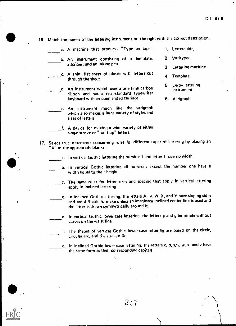
*
,
,
Ix
D I - 97-8
16. Match the names of the lettering instrument on the right with the correct description.
a. A machine that product..i "Type on tape" 1. Letterguide,
b. An instrument consisting of a template, 2. Varitypera scriber, and an inking pen
3. Lettering machine
c. A thin, flat sheet of plastic with letters cutthrough the sheet
4. Template
5. Leroy letteringd. An instrument which uses a one-time carbon instrument
ribbon and has a near-standard typewriterkeyboard with an open ended carriage 6. Varigraph
e. An instrument much like the varigraphwhich also makes a large variety of styles andsizes of letters
f. A dPvice for making a wide variety of eithersingle stroke or "built-up" letters
17. Select true statements concerning rules for different types of lettering by placing an
" X" in the appropriate blanks.
!
a. In vertical Gothic lettering the number 1 and letter I have no width
b. In vertical Gothic lettering all numerals except the number orie hav ?. a
width equal to their height
c. The same rules for letter sizes and spacing that apply in vertical letteringapply in inclined lettering
d. In inclined Gothic lettering, the letters A, V, W, X, and Y have sloping sidesand are difficult to make unless an imaginary inclined center line is used and
the letter is drawn symmetrically around it
e. In vertical Gothic lower-case lettering, the letters p and g terminate withoutcurves on the waist line
f. The shapes of vertical .Gothic lower-case lettering are based on the circle,
circular arc, and the straight line
g. In inclined Gothic lower-case lettering, the getters c, o, s,.v, w, x, and z have
the same form as their corresponding capitals
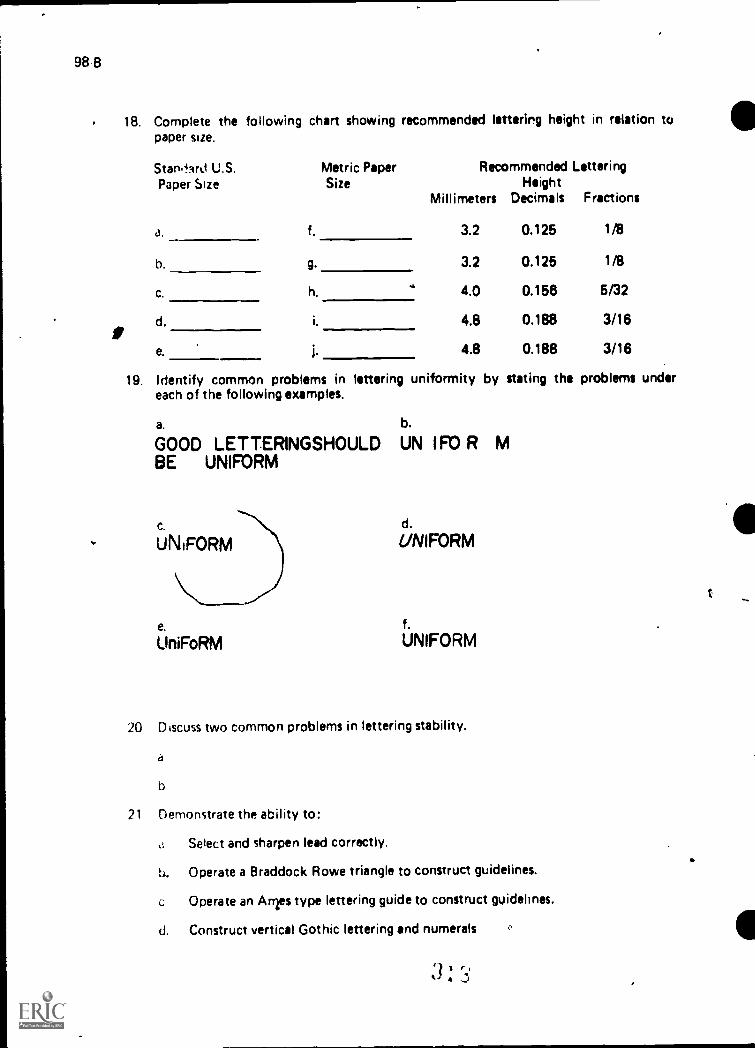
98 8
ar
.,
18. Complete the following chart showing recommended lettering height in relation topaper size.
Stan,lArd U.S. Metric Paper Recommended LetteringPaper Size Size Height
Millimeters Decimals Fractions
a. f. 3.2 0.125 1/6
b. 9. 3.2 0.125 1/8
c. h..
4.0 0.156 5/32
d. i. 4.8 0.188 3/16
e. i. 4.8 0.188 3/16
19. Identify common problems in lettering uniformity by stating the problems undereach of the following examples.
a. b.
GOOD LE T TERINGSHOULD UN I FO R MBE UNIFORM
e.
UniFoRM
d.
UNIFORM
f.UNIFORM
20 Discuss two common problems in lettering stability.
d
b
21 Demonstrate the ability to:
c: Select and sharpen lead correctly.
b. Operate a Braddock Rowe triangle to construct guidelines.
c Operate an Anrs type lettering guide to construct guidelines.
d. Construct vertical Gothic lettering and numerals
k. £
.
t

LETTERINGUNIT II
ANSWERS TO TEST
1. b
2. a
3. b, d, e
D I - 101-8
4. a. For machine drawings, upper case letters are used and may be vertical or inclinedb. For topographic drawings or maps, lower case letters are used for notes
5. a, b, d
6. a, c
7. a, bte, f
8. b, c, e
9. Any three of the following:a. Saves time in productionb. Easy to read and provides drawing consistencyc. Students learn to use it fasterd. Cost of drawings is reduced
10. a, c, d, e, g
11. a, c, d, f
12 b, c, g, h
13
14.
15.
16
a.
b.c
Braddock Rowe triangleAmes type lettering guideParallelograph
a 4 e. 8b. 3 f. 5c. 1 g, 2d. 6 WI 7
a 2 e. /b. 4 f. 6c 8 g. 3d. 1 h. 5
,
a 3 d. 2b 5 e. 1
c 4 f. 6
17. a, c, d, f, g

102 B
,
18. a. A f A4b. B q. A3C. C n. A2(1. D 1, A 1
e. E i AO
19 ..1 Areas are not unitorm between wordsb. Areas are not uniform between lettersc. Letters are not uniform in heightri. Letters are not inclined or vertically uniforme Style of letters is not uniformt. Letters are not uniforrg in stroke thickness
20. Discussion should include:a. On some letters, if the top portion is the same width as the bottom, the letters
appear to be top heavyb. If the center area of certain letters is placed at midheight to the line, it appears to
be below center; therefore, these strokes are placed slightly above the center pointof the letters B. E, F, and H
71 Pei Immance skills evjuated to the satisfaction of the instructor
IP
'?' 1t ,,,, k

I,- 103-B
REPRODUCTIONUNIT III
UNIT OBJECTIVE
After completion of this unit, the student should be able to list the materials and processesinvolved in blueprinting and other reproduction activities in drafting. The student shouldalso be able to list materials and processes in microfilming and operate reproduction equip-ment. This knowledge will be evidenced by correctly performing the procedures outlined onthe assignment and job sheets and by scoring 85 percent on the unit test.
SPECIFIC OBJECTIVES
After completion of this unit, the student should be able to:
1. Match terms related to reproduction with their correct definitions.
2. Distinguish between two types of blueprint machines.
3. Select true statements concerning the uses of the blueprint process.
4. List two advantages and two disadvantages of blueprints.
5. Match materials, equ43ment, and characteristics of diazo dry and wet processeswith their correct de nitions.
6. Select true statements concerning important factors in the diazo dry prirftprocess.
7. List advantages of th- diazo dry print process.
8. Select true statements concerning the diazo wet print process and its advantages.
9. List common problems in the diazo dry print process and how to correct them.
10. Select true statements concerning how to safely use erasing chemicals in diazoprocessing.
11. Discuss the need for correct linework density and how to test for it.
12. Match basic elements of microfilming with their correct definitions.
13. List suggestions for preparing drawings to be microfilmed.
14. Select true statements concerning the advantages of microfilm.
15. Describe the purpose and method for making reproducibles from existingdrawings.

104.B
16. Select true statements concerning the uses and procedures for paste-up drafting.
1;. Select true statements concerning the characteristics of appliques.
18. Arrange in order the steps in using transfer appliques.,
13. Arrange in order the steps in using cutout appliques.
20. List elements of a proper drawing control system..
21. List ways a proper drawing control system benefits a drafting organization.
22. Discuss correct storage of drawings and prints.
23. Discuss the proper distribution of completed drawings.
24. Demonstrate the ability to:
a. Make blueline or blacklineprints.
b. Operate a hlueline machine.
:
4
\

D I 105-B
REPRODUCTIONUNIT III
SUGGESTED ACTIVITIES
I. Provide student with objective sheet.
II. Provide student with information, assignment, and job sheets.
III. Make transparencies.
IV. Discuss unit and specific objectives.
V. Discuss information sheet.
VI. Discuss the procedures outlined in the assignment and job sheets.
VII. Discuss with the class the safety precautions required when using chemicalsin various reproduction processes.
VIII. Have examples available of materials reproduced by methods other than blue-printing or the diazo processes such as Thermo-Fax or Verifax.
IX. Demonstrate how to opaiate a print machine.
X. Demonstrate how to clean a print machine.
XI. Discuss other types of reproduction methods.
XI I. Give test. a
INSTRUCTIONAL MATERIALS
I. Included in this unit:
A. Objective sheet
B. Information sheet
C. Transparency masters
1. TM 1--Reproduction Processes
2. TM 2--Blueprint Process
3. TM 3--Dry Print Process
4. TM 4--Moist Print Process
5. TM 5--Fourth Generation Reproduction
6. TM 6--Microfilm System from Original Drawing to Distribotion ofPrints or Aperture Cards
3" 1

106 13
Assignrnprit Sheet I Mak" alueline Pt
.)l) ;;neot 1 Opprat L1teline Machine
Tort
Answers to test
Brown, W C Drafting for industry,. South Holland, IL 60473 fli"600dh,'art Willcox Company, Inc., 1974
DAcion, .John rhomas and Henry Cecil Spencer Basic Technical Drawing
New York, NY 10022: Macmillan Publishing Co., Inc., 1968
:socke Frederick E., et al Technical DrawingINWew York, NY 10022M r-mil!an Pubhshinq Co., inc., 1980.
Jemen, cil and Jay Helsel Engineering Drawing and Design. New York,NY Cireci, Divis:oniMcGiaw Hill Book Company 1979
P Drafting Technology and Practke Peoria, IL 6161!).b, ilnett Co., Inc 1973..
\, )( .,ona, Corricuum Development and Researcli Center Basic Drafting
Nat, Loue:I ma 71457 State of Louisiana Vocational Conicuium n N.t.duornent ald Research Center , revised 1979
)I),.0' if

REPRODUCTIONUNIT III
INFORMATION SHEET
I. Terms and definitions
D I - 107-B
A. Drawing reproduction-Making copies from completed drawinparency 1)
s (Trans-
B. Back curl--The curl of paper toward the uncoated side
C. Face curl--The curl of paper toward the coated side
D. Silk screening--Stenciling through a silk screen to form an imai5e
E. Brownprint process-Reproduction method using light-sensitive iron andsilver salts which will produce a negative sepia image from a positive master
F. Composite print--Print made by combining the parts of two Pr more masters
G. Contact print--Print made by placing a master or an original in contact withlight-sensitive material while exposure is being made
H. Contrast--The difference between the image and background areas of aprint
I. Core--Tube on which print paper, film, sepia, or other material is wound,
J. Density--The darkness of an image (linework or lettering) area
K. Developer-Chemical agent used for treating an exposed light-sensitivematerial to make the image visible to the eye
L. Development--Any process used for rendering an image visible
M. Discoloration--Yellowing or other color char?ges of white areas on prints..1
N. Double coated stock-Duplicating material which has a sensitized layeron each side
0. Double feed--Improper feeding of two sheets of duplicating paper instead ofone
P. EradicatorChemical solution containing acid designed to bleach out unwanted portions of a print
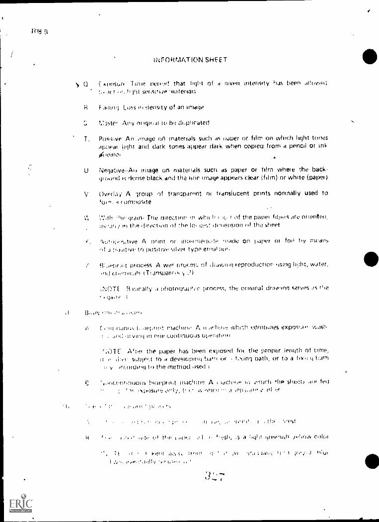
lNrOitrAATION SHEET
Anosuri nere.,d that light of <1 filvfll intensity has been apowedac r ors li int serssiri re .14 ateriar,
H Failing Loss v. density of an imdge
3srer Ansi or iginai to ha drsphrated
T. Posonve An -image on materials such as thIper or film on which light tonesappear light and dark tones appedr dark when copieu from a pencil or ink
U Negative-Au image on materials such ds paper or film where the back-rwid i dcose black and the hne image appeers clear (film) or white (paper)
Overlays' A lroup of transparent ni trdnsiucent Prints normally used ton, a r ornnorate
"le grain- The uire;.t inn ri whkh of the paper Niels are or ienteo,in the direction I the lo, uv$ dimension of thii sheet
'Auto; we A nrim or inn-fined', te inade on 1,dN't or foil by meansof :io.ative to positive silver type eri,u1;lon
BLienr.nt process A wet proces., nf di (owing reproductron using licht, water,rod chemicals IT: ansparciii y
'NOTE R roral!y nhotograpic process, the or mina; draviann serves sis ttleijoi!v ;
.1 r
(soli aluous is sievirit machirii, A II arinr,.., combines exposisre wushs II Vintj Ill one continuous
After the paper has been exposed for the proper ierulth of time,cntnP'.t to a developing hatn or ts \Irv) oath, or to a fix,' q Leh
irir.orunio to the method ,ised
C burepriht machine A. 1 'actinic flip fed; \;11)stir,j tr 0. I '" ,Pr),.01" aslser
If ;if
i' xi:
,11).: Is a ',gilt irreenish cidoi
. i-I i fr id', 1,%. I Lc, 1 ;re
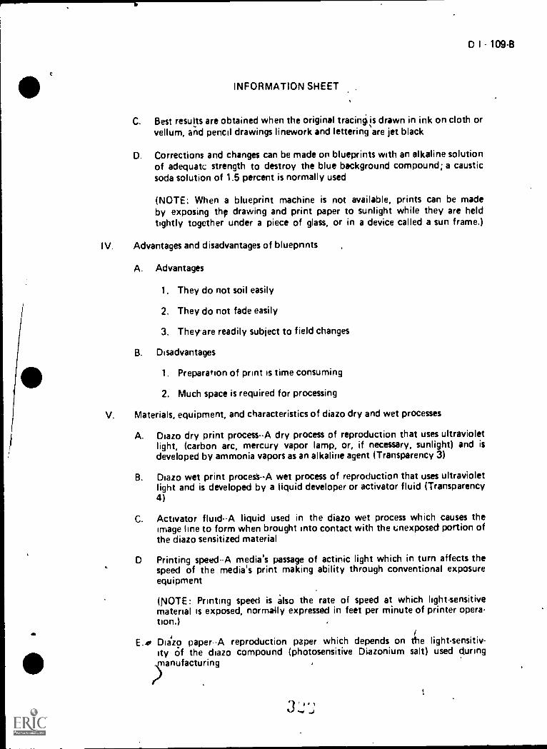
0 I - 109-B
INFORMATION SHEET
C. Best results are obtained when the original traciniis drawn in ink on cloth orvellum, and pencil drawings linework and lettering are jet black
D. Corrections and changes can be made on blueprints with an alkaline solutionof adequatc strength to destroy the blue background compound; a causticsoda solution of 1.5 percent is normally used
(NOTE: When a blueprint machine is not available, prints can be madeby exposing the drawing and print paper to sunlight while they are heldtightly together under a piece of glass, or in a device called a sun frame.)
IV. Advantages and disadvantages of bluepnnts
A. Advantages
1. They do not soil easily
2. They do not fade easily
3. They are readily subject to field changes
B. Disadvantages
1. Preparation of print is time consuming
2. Much space is required for processing
V. Materials, equipment, and characteristics of diazo dry and wet processes
A. Diazo dry print process--A dry process of reproduction that uses ultravioletlight, (carbon arc, mercury vapor lamp, or, if necessary, sunlight) and isdeveloped by ammonia vapors as an alkaline agent (Transparency 3)
B. Diazo wet print procest--A wet process of reproduction that uses ultravioletlight and is developed by a liquid developer or activator fluid (Transparency4)
C. Activator fluidA liquid used in the diazo wet process which causes theimage line to form when brought into contact with the unexposed portion ofthe diazo sensitized material
D Printing speed--A media's passage of actinic light which in turn affects thespeed of the media's print making ability through conventional exposureequipment
(NOTE: Printing speed is also the rate of speed at which light-sensitivematerial is exposed, normally expressed in feet per minute of printer opera-tion.)
E.40 Dia'zo paperA reproduction paper which depends on tlhe light-sensitiv-ity of the diazo compound (photosensitive Diazonium salt) used during

110
INFORMATION 1-f.r..:ET
F F le aging The change in appearance of a diazo p r storaue ficl exposedto light
G F iii OuSitlye- Firm base which carries a wit we image, often ci photographicm iterial which it necessarN, can serve es oldster for diazo-type prints
H Printer section -Area of print machine used to expose light sensitive materials
Dew loper soction -Area of print macr int used to develop Itql.t sensitivematerials
J Shelf life-Time period before deterioration renders a sensitlied materialunusable
K Reproducible-Item capable of being used as a master for makihg prints
L. Sensitized-A reproduction material coated with a Ant sensitive corn-ound
'e i,rinediatt!- The translucent reproiluction -nade on" vellum, cloth, or'oil made from an original drawing and risen in place of the original for',taking f)ther prints-
;NOTE Sometimes the original is filaced on the intermediate paper upsidedown so the drafter can draw on the side of tile r away from Cie dyelines A typical use of Nples occurs in architectu, ii wor k xhen severalcopies are made of trw basic floor plan of d budding, I e cop,cs are then usedfor framing, plumbing, heating, ventilating end air 00hnditioning, electrical,arvi reflecteo ceiling work )
N Polvster fkm -Diazu-sensinzed transparent collolose acetates
(NOTE. Polyester film is sometimes referred to as foil )
O Diai0 color film -Diazo sensitized material for list: (10 dial() i In y process
to produce audiovisual aides
VI. Irioortant factors in the diazo dry print process
A. '..Thp nrncess dependf on the transn .,,sion of Wilit il, ()ugh the ortginal 4or the reproduction ot poSitNe prints
B. Subject matter may be pen, pencil, I ypewrytn, or printed matte-, orany opaque image-
C No negative step is involved: positives ore used to obta.n pksitvP priqts
(NOTE: To remove the ammonia odor Iron, ihe Orin!, feed the print intothe printer section with the back of the print next to the war-r, glass cylindr:rsur,oundina the lamp.)
fool,

D I -111-B
INFORMATION SHEET
VI I. Advantages of the diazo dry print process
A. Sensitized materials can be handled under normal indoor illumination
B. Prints may have black, blue, or red lines on a white background depend-ing upon which paper is used
C Prints can be worked on easily with pen, crayon, or pencil
D. Intermediates can he made of the original to save wear on the original, theseintermediates can be made on special paper (sepia), cloth, or foil
E. Changes can be made to intermediates with correction fluid
VIII. Diazo wet print process and its advantages
A. It is similar to the diazo dry process except paper is fed through a specialdeveloper which dampens the coated side of the paper with developingsolution
B. Prints may have black, red, brown, or blue lines on a white backgroundsimply by selecting the appropriate paper
(NOTE: These prints along with diazo dry prints have largely replaced
the more burdensome blueprint process.)
IX. Common problems in diazo dry print processing and how to correct them
A. Print with a green tint Ammonia may be too cold or too old or tubescontrolling ammonia flow may be clogged, need cleaning, or flow adjusted
B. Print with streaking on it-Ammonia flow is excessive and rleds to beadjusted
X. How to safely use erasing chemicals in diazo processing
A Eradicator for sepia intermediates is a one-step method, but the eradicatorcontains acid and application should be made with care
B. Erasing sfluid for foils is a two step method involving application of a first
fluid containing hydrochloric acid
(NOTE: This reacts with the metallic silver in the sheet to produce a \Nhite
salt of silver.)
C The second step in erasng foils involves application of d fluid containingthiourea which dissolves the silver salt
(NOTE. The silver salt must be completoly dissoloqf or it as j
yellow stain when exposed to light I
ki)
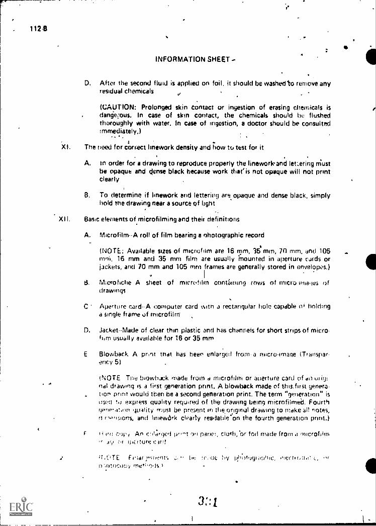
112
INFORMATION SHEET-
D. After the second fluid is applied on foil, it should be washecrto remove anyresidual chemicals
(CAUTION: Prolonged skin contact or ingestion of erasing chemicals isdanget.ous. In Case of skin contact, the chemicals should bo flushedthoroughly with water. In case of ingestion, a doctor should be consultedimmediately,)
.
The need for cortlect linework density and how to test for it
A. In order for a drawing to reproduce properly the linework and letering Mustbe opaque and dense black because work that' is not opaque will not printclearly
B. To determine if linework arid lettering are opaque and dense black, simplyhold me drawing near a source of light
XII. Basic elements of microfilming and their definitions
A. Microfilm-A roll of film bearing a nhotographic record
(NOTE: Available sizes of microfilm are 16 rtim, 3e mm, 70 mm, and 105rnrri, 16 mm and 36 mm film are usually 'mounted in aperture cards orjackets, and 70 mm and 105 mrn frames are generally stored in envelopes.)
M:crohche A sheet of microfilm contiening rows of micro images ofdrawings
C Aperture card--A computer card wan a rectangular hole capable of holdtnga single frame of microfilm
D. Jacket--Made of clear thin plastic and has channels for short strips of micro-him usually available for 16 or 35 ram
E Blowback A print that has been enlarged from-a necrogrnage (Transpar-ency 5)
!NOTE Tne h-tow.eac.. made from d microfilm Or aperture card of dli ()I IU:ndl drawing ts a first generation print. A blowback made of this.flist genera-tion onnt would tben be a second generation print. The term "generation" isused ro express quality required of the drawing being microfilmed. Fourthqpno.1:ont qu4Iity must be present hi the.original drawing to make ail notes,rf r,.."sionS, and linewdrk clparly readahle'on the fourth generation print.)
frt1 cot' y An e:#1:freierf pr--,t oft pahef, Cloth, br toll made from .3 MICrOfiltli'' Jilt ipErtUrk: ( irr!
ir ,f;tTE Frtcfr rrrrient; tis fy p..hott)914-.101c, otertu,;tot(),-,Otoco;)y rrier;.0,,s.)
3:4

0 I - 11343
. INFORMATION SHEET
XIII. Suggestions for preparing dra%. 'igs to be microfilmed
A. Check linework and lettering for uniformity and density
B. All lines of theism@ type must be the same width-.,
C. Ink lines produce the best results tin microfilm..
(NOTE: Ink lines are sharper, blacker and have more density than, pencillines. They also dry flat so there is less reflection.) :
D. Experimentation should be done with various pencils, inks, and vellums
E. Lettering must be large enough to reduce photographically and then beenlarged without loss of clarity .
Example: Some companies establish lettering height standards formicrofilm; one such standard is as fpllows for 35 mm micro-film:
Standard U.S.Paper Size
Metric PaperSize
RecOmmended LetteringHeight
Millimeters Decimals(Inches)
Fractions(Inches)
'AEl
CDE
A4A3A2AlAO
3.23.24.04.84.8
0.1250.125
' 0.1560.1880.188 \
1/81/85/323/163/16
(NOTE: The larger the drawing size the larger the lettering regLited.)
F. The letters must be formed very carefully and not crowded or they willrun together when reduced
G. When lines of lettering are used, the space between the lines should be aminimum of one-half the height of the letters with more space betweenparagraphs
H. If lettering is typed on, care must be used to produce a dense, uniform, andsolid letter
(NOTE: Ribbons with too much ink smear, and worn ribbons, type, andtypewriter p!atens produce a poor letter; carbon ribbons usually workbest.)
IA
I. Exercise care when erasing because all smears and dirt will show on themicrofilm
(NOTE: If a portion of the drawing is cut away and replaced with newmateriaI, the material should be of the same type and match the origi-
4 nal background.)
3 ). 0 ...

1148
INFORMATION SHEET
J. Keep drawing covered when not working on it; when working on thedrawing, rover areas not needed, use a drafter's brush and dry cleaning pad,and keep perspeation from hands and arms off the drawing
v.
K. Drawings that are to be microfilmed should be stored flat
(NOTE. After drawings have been rolled or made from rolled stock theyare difficult to flatten.)
L. Do not use the original drawing for reference; if a print is needed it shouldbe made from the microfilm
XIV Advantages of microfilm (Transparency 6)
A. Used where large numbers of drawings are involved
B. Used to store drawing duplications in a small amount of filing space
C Used to duplicate copies for security purposes
Examples: Burglary, vandalism, fire
D. Aperture cards may be viewed in a reader, a full.size print may be made froma reader-printer unit when produced through a' C size
E. Aperture cards are basically the same as cards used in electronic computers;equipment is capable of sorting, filing, and retrieving these cards
F. Duplicate aperture cards and drawing reproductions to any desired sizemay be produced on specialized equipment
G. Microfilm drawings may be sent to another of flee at less expense than stan -dard prints
XV Purpose and method for making reproducibles from existing drawings
A. Purpose--Used when a new drawing cah be made from an existing drawinggirwith only minor changes
B Method
Make transparent or translucent print of the m winal drawing
2. Remove unwanted information from an old print and then ddd newinformation
(NOTE. A problem may be encountered when old diawloris do notconform with the newest drafting standards I
D I - 115-B
INFORMATION SHEET
XVI. Uses and procedures for paste-up drafting
A. Uses
1. With new designs, some features may be repetitive; therefore, paste-updrafting is possible
1 A major advantage of . paste-up drafting is that it reduces drawingand rechecking time
B. Procedures
1. Make transparent or translucent print of the original drawing
2. Cut out needed existing drawings, charts, notes, or drawing forms
3. Arrange information on a clear acetate sheet using the correct size andproper arrangement
4. Tape pieces to the acetate sheet with transparent tape
5. Make a transparent or translucent print to form a new original
6. Remove pieces from the acetate sheet, discard used transparent tape,and remove transparent tape residue from the drawing pieces andacetate sheet
7. Store drawing pieces and acetate sheet for future use
8. Add additional drawings, dimensions, and notes
XVII. Characteristics of appliques
A. Appliques are overlays which are pressure-sensitive and printed on blank,transparent, or translucent sheets with adhesive backing
B. Time is saver, when notes, symbols, shapes, or parts are used repeated-ly
(NOTE: The mat surface on appliques will accept pencil or ink lines, and canbe used in a typewriter.)
C. Appliques can be used for long notei which can be typed faster than theycan be lettered, or for making char.ges or corrections to drawings or lists
D. Appliques are used extensively in industry, mostly in the piping and elec-tronics areas
E. Appliques are available in two types, transfer and cutout

0
INFORMATION SHEET
XVIII. Steps in using transfer appliques
A. Remove the carrier from the image sheet
B. Place the image in the proper position on the drawing
C. Rub over the image to be transferred with a blunt object Of a burnish-ing tool
D. Lift the transfer image carefully so the image will remain on the drawing
E. Place the carrier sheet over the image and rub or reburnish it again
(NOTE: Transfers sometimes crack with age or come off on the gloss cylin-der of a print machine, but they can be secured with transparent tape if tapeis free of fingerprints and the tape dispenser ends are removed.)
XIX. Steps in using cutout appliques
A. Position the image in the correct location on the drawing and lightly markreference points on the drawing
B. Lift the image and remove the backing material on the applique
C. Reposition the image in the correct place on the drawing and lightly rub orburnish it
D. Use a razor knife to \cut away unwanted material from around the image
(NOTE: Use caution with a razor knife, so the media surface will not becut; backing material should be used.)
E. Reburnish the area
XX. Elements of a proper drawing control system
A. Drawing numbers
B. Proper methods of filing
C. Microfilming
D. Security files
E. Print making and print distribution control
XXI. Ways a proper drawing control system benefits a drafting organizat:on
A. Allows the person in charge to know the status of a cjrawing at all times
(),1..q.1 .1

INFORMATION SHEET
B. Minimizes the possibility that an original drawing will be'damagtd frombeing handled for printing, changes, or checking
,C. Controls the distribution of prints to the appropriate people
XXII. Correct storage of drawings and prints '
A. Drawings may be stored in large, flat file drawers or hung vertically in acabinet or a freeitanding file
B. Prints may be folded and filed in standard office file cabinets, or extra largeprints can be rolled and stored in cibinetsitubes, or tubes in cabinets
XXIII. Proper distribution of completed drawings
A. Whether prints or intermediates, copies should be made for distribution
B. The original should NEVER be sent but
t... *-1 . I
\
,

mil
.
..
I
II
Reproduction Pmcesses
IREPRODUCTION PROCESSES
I
TOCHEMICAL
I
1SPECIAL
*
u
TRANSMITTED UGHT(CONTACT)
REFLECTED UGHT(PROJECTION)
*1. VANDYKE2. BLUEPRINT3. blAZO, MOIST4. DIAZO, DRY5. PHOTOGRAPHIC
CONTACT PRINT
1. PHOTOGRAPHICREFLEX PRINT
2. PHOTOSTAT. MICROFILM
6...--.21
1. LITHOGRAPHY2. PHOTOGRAVURE3. LETTERPRESS
3::7os.
I ..[1: IMMEOGRAWH2. HECTOGRAPH3. TYPEWRITER

Tracing
a
Blueprint Process
Light
\\\ ati, ,,,
/
CONTACT
I
SensitizedPaper
POTASSIUM
DICHROMAUJATH
3 3 9
,,
EXPOSURE
A
WATER RINSE
I
\
\\
WATER WASH \
*DRYING
34 1

_
it
Tracing,
%
.,
..
Dry Print ProcessI
,
.Z7/.- h..4:
3-11
CONTACT
&JP
Sensitized Paperr
1EXPOSURE
DEVELOPING WITH AMMONIA VAPORS,
3:2

I .
Moist PInt Process
Tracing
CONTACT
311;
Sensitized Paper EXPOSURE
LIQUID DEVELOPER
3'41
,

Fourth Generation Reproduction
IoRicaNALDRAWING
I
MASTER°INTERMEDIATE
ORMICROFILM
I
FIRST GENERATIONREPRODUCTIONMADE FROMMASTERINTERMEDIATE
SECOND GENERATIONREPRODUCTIONMADE FROMREVISION OFFIRST GENERATIONREPRODUCTION
(PRINT)
THIRD GENERATIONREPRODUCTIONMADE FROMREVISION OFSECOND GENERATIONREPRODUCTION
(PRINT)
FOURTH GENERATIONREPRODUCTIONMADE FROMREVISION OFNIRD GENERATIONREPRODUCTION
(PRINT)

D I 129-6
Microfilm System from Original Drawing
to Distribution of Prints or Aperture Cards
0. ORIGINAL DRAWING
1
<CAMERA PROCESSOR
INSPECTION FORMICROFILM OUALITY
4 tCARD
DUPLICATOR
ELECTRONIC ACCOUNTINGMACHINE PUNCHINGIDENTIFYING INFORMATIONIN CARD
DISTRIBUTION OF PRINTS
TO STORAGE
DUPLICATE
4CARDS
1/
ELECTRONICACCOUNTING
MACHINECARD 'SORT
FORDISTRIBUTION
READER-PRINTER
34.7
,1
I
REVISION AND UPDATING
TM 6

D I - 131-B
R EPRODUCTIONUNIT III
ASSIGNMENT SHEET #1--MAKE BLUELINE OR BLACKLINE PRINTS
Directions: Make blueline or blackline prints of 'several drawings done to this date usingeither a diazo dry process machine or a diazo wet process machine.
(NOTE: Instructor may wish to have some drawings reproduced on intermediates such assepia or foil.)
3 4
D I - 133-8
REPRODUCTIONUNIT III
,
JOB SHEET #1OPERATE A BLUELINE MACHINE
I. Tools and equipment
A. Machine as selected by instructor
B. Safety gear as specified by instructor
(NOTE: Before doing any of the following remove all rings, loose jewelry,and if necessary tie back hair.)
II. Procedure
I* AA. Start up t
1. Remove cover
2. Turn on exhaust fan
3. Turn on ammonia pump BEFORE turning machine on
4. Turn from off to blower-dryer motors and wait approximately 5seconds
5. Turn from blower dryer motors to heaters and wait approximately 5seconds
6. Turn from heaters to lamp
7. Be sure switch is set to forward
8. Set ammonia control at approximately 15 drops per minute
9. Set speed control and wait approximately 15 minutes for machineto warm up
B. Make blueline
C. Shut down
1. Turn ammonia flow switch off GENTLY
2. Turn switch from lamp to heaters and wait approximately 5 seconds
3. Turn from heaters to blower dryer motors and wait approximately 5seconds
4. Turn from blowd dryer motors to off
5. After machine has turned off, turn off the ammonia pump
3 4 3
1 34 B
JOB SHEET *11,
6. Turn off exhaust fan
7. Cover machine
(NOTE: Ask instructor to verify how the machine in the draftingdepartment works.)
I, am1eI., 1_,, .
..

REPRODUCTIONUNIT III
NAME
TEST
1. Match the terms on the right to the correct definitions.
_ 0 1 - 13543
a. Chemical solution containing acid designed tobleach out unwanted portions of a print
b. Improper feeding of two sheets of dupli-cating Frper instead of one
c. Duplicating material which has a sensi-
tized layer on each side
d. Yellowing or other color changes of whiteareas on prints
e. Any process used for rendering an imagevisible
f. Chemical agent used for treating an exposedlight-sensitive material to make the imagevisible to the eye
g. The darkness of an image area
h. Tube on which print paper, film, sepia,
or other material is wound
i. The difference between the image and back-ground areas of a print
i. Print ma& by placing a master or an originalin contact with light-sensitive material whileexposure is being made
k. Print made by combining the parts of twoor more masters
I. Reproduction method using light-sensitiveiron and silver salts which will producea negative sepia image from a positive master
m. Stenciling through a silk screen to forman image
331
1. Autopositive
2. Overlay
3. Positive
4. Fading
5. Eradicator
8. Double coatedstock
7. Development
8. Density
9. Contrast
10. Composite print
11. Silk screening
12. Back curl
13. Drawing repro-duction

138-8
n. The curl of paper toward the coated side
o. The curl of paper toward the urcoatedside
p. Making copies from completed drawings
q. Agaprint or intermediate made on paper orfoil by means of a positive to positive silver-type emulsion
r. The direction in which most of the paperfibers are oriented, usually in the direction ofthe longest dimension of the sheet
s. A group of transparent or translucent printsnormally used to form a composite
t. An image on materials such as paper orfilm where the background is dense blackand the line image acipears clear or white
14. Face curl
15. Brownprintprocess
16. Contact prirt
17. Core
18. Developer
19. Discoloration
20. Double feed
21. Exposure
22. Master
23. Negative
24. With thegrain
u. An image on materials such as paper or 25.film on which light tones appear light anddark tones appear dark when copied from apencil or ink original
v. Any original to be duplicated
w. Loss in density of an image
x. Time period that light of i given inten-sity has been allowed to act on light-sensitivematerials
y. A wet process of drawing reproductionusing light, water. and chenlicals
Blueprintprocess
2. Distinguish between the two types of blueprint machines by placing an "X" to theleft of the description of a continuous blueprint machine.
a. A machine in which the sheets are fed through for exposure only, thenworked in a separate washer
b. A machine which combines exposure, washing, and drying in one contin-uous operation
ej dv,

0 I - 137-B /3. Select true statements concerning the uses of the blueprint process by placing an
in the appropriate blanks.
a. Of several reproduction p..xesses in use, blueprinting is the newest
b. Best results are obtained when the original tracing is drawn in ink on cloth orvellum, and pencil drawings linework and lettering is let black
c. The coated side of the paper, when fresh, is a light greenish yel:ow color
d. Corrections and changes cannot be made on blueprints
4.. List two advantages and two disadvantages of blueprints.
a. Advantages
1)
2)
b. Disadvantages
1)
2)
5. Match the materials, equipment, and characteristics ofon the right with the correct definitions.
a. Diazo sensitized material for use with thediazo dry process to produce audiovisual aides
b. Diazo-sensitized transparent cellulose acetates
c. The translucent reproduction made onvellum, cloth, or foil made from an originaldrawjng and used in place of the original formaking other prints
d. A reproduction material coated with a light.sensitive compound
e. Item capable of being used as a master formaking prints
f. Time period before deterioration renders
a sensitized material unusabie
g. Area of print machine used to develop light-sensit ive materials
3
diazo dry and wet processes
1. Diazo dryprint process
2. Diazo paper
3. Diazo wetprint process
4. Printing speed
5. Activator fluid
6. Diazo color film
7. File aging

1394.
Ii
ri.
h. Area of print machine used to expose light.sensitive materials
i. Film base which carries a positive image,often a photographic material which, ifnecessary, can serve as master for diazo-typeprints
The change in appearance of a diazo print instorage not exposed to light
k. A reproduction paper which depends onthe light-sensitivity of the (Imo compoundused during manufacturing
I. A media's passage of actinic light whichin turn affects the speed of the media'sprint making ability through conventionalexposure equipment
in. A liquid used in the diazo wet process whicffcauses the image line to form when broughtinto contact with the unexposed portion ofthe diazo sensitized material
n. A wet j.rocess of reproduction that usesultraviolet light and is developed by a liquiddeveloper or activator fluid
o. A dry plocess of reproduction that usesultraviolet light and is developed by ammoniavapors as an alkaline agent
8. Polyester film
9. Film positive
10. Intermediate
11. Printer section
12. Sensitized
13. Developer section
14. Reproduciblp
15. Shelf.life
,
i
. _
6. Select the true statements concerning important factors in the diazo dry print processby placsni an " X" in the appropridte blanks.
_a. The process depends upon the transmission of light through the original
for the reproduction of positive prints _.
I.....,
b. Subject matter may be pen, pencil, typewritten, orany opaque image
tc,)
c Only negative steps are involved in the process
7. List thsree advantages of the diazO dry print process.
a.
b.
c =41
I'lI..; .,,
printed matter, or
,

D I - 1398
8. Select true statements concerning the diazo wet print process and its advantages byplacing an "X" in the appropriate blanks.
a. Prints may have only black or blue lines on a white background by selecting_
the appropriate paper
b. It is similar to the diazo dry process except paper is fed through a specialdeveloper which dampens the coated side of the paper with developingsolution
9. List two common problems in the diazo dry print process and how to correct them.
a.
10. Select true statements concerning how to safely use erasing chemicals in diazo pro-cessing by placing an "X" in the appropriate blanks.
a. Eradicator for sepia intermediates is a one-step method, but the eradicatorcontains acid and application should be made with care
b. Erasing fluid for foils is a two-step method involving application of a firstfluid containing acetic acid
c. After the second fluid is applied on foil, it should be washed to remove anyresidual chemicals
11. Discuss the need for correct linework density and how to test fO-r it
12. Match the basic elements of microfilming on the right to the correct definitions.
a. A print that has been enlarged from a micro-image
b. An enlarged print on paper, cloth, or foilmIde from a microfilm image or aperture card
c. A sheet of microfilm containing severalrows of micro-images of drawings
d. Made of clear thin plastic and has channels forshort strips of microfilm usually available for16 or 35 mm
1. Microfilm
2. Microfiche
3. Aperature card
4. Jacket
5. Blowback
6. Hard copy

140-B
)
p.
e. A roll of film bearing a photographic record
f. A computer card with a rectangular holecapable of holding a single frame of microfilm
13. List five suggestions for preparing drawings to be microfilmed.
a.
h.
e.
14. Select true statements concerning the advantages of. microfilm by placing anin the appropriate blanks.
a. Used to.store drawing duplications in a small amount of filing space
b. Duplicate aperlure cards and drawing. reproduction') to anyldesired sizemay be produced on specialized equipment
c. Used where small numbers of drawings are involved
d. Postage requirements are higher for microfilm when sending to anotheroffice becomes necessary
e. Used where large numbers of grawings are involved
15. Describe the purpose and method for making reproducibles from existing drawings.

D 1 141-B
16. Select true statements concerning the uses and procedures for paste-up drafting byplacing an "X" in the appropriate blarks.
a. With new designs, most features may not be repetitive; therefore, pasteupdrafting is possible
b. A major disadvantage of paste-up drafting is that it increases drawing andrechecking time
c. Make transparent or translucent print of the original drawing
d. Arrange information on a clear acetate sheet using the correct size and
proper arrangement
e. Tape pieces to the acetate sheet with opaque tape
f. Make a transparent or translucent print to form a new original
g. Store pieces attached to the acetate sheet
h. Add additional drawings, dimensions, and notes
17. Select true statements concerning the characteristics of appliques by placing an "X" inthe appropriate blanks.
a. Appliques are overlays which are pressure-sensitive and printed on blank,transparent, or translucent sheets with adhesive backing
h. Use of appliques increases time needed to work with notes, symbols, andshapes
c. Appliques can be used for long notes which can be typed faster thon theycan be lettered, or for making changes or corrections to drawings or lists
d. Appliques are more practical for home use than they are for industry
e. Only one type of a0plique, the transfer, is available
18. Arrange ,n order the following steps in using transfer appliques by placing the number"1" to the left of the first step, "2" to the left of the second step and continuethrough all steps.
a. Lift the transfer image carefully so the image will remain on the drawing
b Remove the carrier from the image sheet
c. Place the carrier sheet over the image and rub or reburnish it again
d. Rub over the image to be transferred with a blunt object or a burnish-
ing tool
e. Place the image in the proper position on the drawing

142 B
19 Arrange in order the following steps in using cutout appliques by placing the number"1' to the :eft of the fiqt step, "2" to the left of the second step and continue throughjh stepl
1.:ft the image ard romove the backing material on the applique
P, Reposition the linage in the correct place on the drawing and lightly rub orbdrilish it
, Reournish the al« a
(I Position thi, image in the correct location on the drawing and lightly markreference points on the drawing
r. Use a razor knife to cut away unwanted material from around the image
ist thrpo e!eir, nts of a oroper drawing control system
2 1 List thriv, ways a proper }drawing controi system benefits a drafting orgaruzation.
22 frsc.,s,, correi t storage of drawing anu prints
s Dim us. t,i4, ;:rooty di;tribution r.ompieted drawings

D I - 143-B
\0 24. Demonstrate the ability to:
a. Make blueline or blackline prints.
b. Operate a blueline machine.
(NOTE: If these activities have not been accomplished prior to the test, ask yourinstructor when they should be completed.)
4)
t

D I 1458
REPRODUCTIONUNIT III
ANSWERS TO TEST
1. a. 5 h. 17 o. 12 v. 22
b. 20 i. 9 4f).13 w. 4
c. 6 I. 16 q. 1 x. 21
d. 19 k. 10 r. 24 y. 25e. 7 I, 15 s. 2
f. 18 m. 11 t. 23
g. 8 n. 14 u. 3
2. b
3. b, c
4. a. Advantages (any two of the following)1) They do not soil easily2) They do not fade easily3) They are readily subject to field changes
b. Disadvantages1) Preparation of print is time consuming2) Much space is required for processing
5. a. 6 e. 14 i. 9 m. 5
b. 8 f. 15 I. 7 n. 3
c. 10 g. 13 k. 2 o. 1
d. 12 h. 11 I. 4
6. a, b
7 Any three of the following
a. Sensitized materials can be handled under normal indoor illumination
b. Prints may have black, blue, or red lines on a white background depending upon
which paper is usedc. Prints can be worked on easily with pen, crayon, or pencil
d. Intermediates can be made of the original to save wear on the original, these inter-mediates can be made on special paper, cloth, or foil
e Changes can be made to intermediates with correction fluid
8. b
9. a. Print with a green tint--Ammonia may be too cold or too old or tubes con-trolling ammonia flow may be clogged, need cleaning, or ammonia flow ad-
justedb. Print with streaking on it--Ammonia flow is excessive and needs to be adjusted
10. a, c

146-B
11 fIlscu',. sJ
ooler to, d ("" U rt produce Inoue, v the unework dod lettering must beup3que and (h nse blar k by 'ause work that is tv)t opaque will not pint clearlyTo deter U Ifl f 11.)ework and lettering are opaque and dense black, simply holdthe driwilifi new sourGe of light
4. 12. d. 4
e 1
2 f 3
13 Any 'iv, tne fohowng
a Check linework and lettering for uniformity and densityb All hnes of the same type must be the same width
. Ink lines produce the best reiults on microfilmd Experimentation should be done with various pencils, inks, and vellurns
ettermq .uust be large enough to reduce photographically and then be enlargedwithout In,s of clarityThe letters must be fornied very carefu!Iy and not crowded or they will run()nether VI lit educed
Wh.:11 Itm:s of lettering are cr,ed the Sfleiro between the lines should be a minimum«.,rie half the herght of the lt,tte-s with more ;nice between paragraphsIt letterinij is typed on, care must be used to produce a dense, uniform andsolid letterL KOrcIse (Ire whim erasing Hca 1SP all smi ors and dirt will show on the microfilmKeel, (irawing covered when not working on it, when working on the drawing,.ver drezb not neimed, use a drafter's brw;h and dry cleaning pad, and keepper speatiun from hands and drmc off ,the drawingf)rawings that are to be microfiimed should t,e stored flatD(, not IP, the (irigmal draenng for reference, if a print is needed it should he
fr011$
1'; I,
15 Des( uution
I kou \,tvhen new drawing rari mane f( rn an existing drawing withr chdiulps
1) rilfO. 1101, trarr p ;rent or tr rv,lurent or [PI ,,f the original drawing7 P um dri' lpforrnd.,on frop old punt and Ikon add new infor
18 t 4

D I 147-13
19. a. 2 d. 1
b. 3 e. 4C. 5
20. Any three of the following:
a. Drawing numbersb. Proper methods of filingc. Microfilmingd. Security filese. Print making and print distribution control
21. a. Allows the person in charge to know the status of a drawing at all timesb. Minimizes the possibility that arrtriginal drawing will be damaged from being
handled for printing, changes, or checkingc. Controls the distribution of prints to the appropriate people
22. Discussion should include:
a. Drawings may be stored in large, flat file drawers or tp.ing vertically in a cabinet ora free-standing file
b. Prints may be folded and filed in standard office file cabinets, or eXtra large printscan be rolled and stored in cabinets, tubes, or tubes in cabinets
23. Discussion should include:
a. Whether prints or intermediates, copies should be made for distributionb The original should NEVER be sent out
24. Evaluated to the satisfaction of the instructor.

I
D I - 149-B
DRAWING SHEET LAYOUTUNIT IV
UNIT OBJECTIVE
After completion of this unit, the student should be able to select items of informationrequired on a correct drawing sheet layout and the items in working drawings that arechecked for accuracy. This knowledge will be evidenced by correctly performing theprocedures outlined on the assignment sheet and by scoring 85 percent on the unit test.
SPECIFIC OBJECTIVES
After completion of this unit, the student should be able to:
1. Match terms related to a drawing sheet layout with their correct d-'initions:
2. Match types of working drawings with their correct definitions.
3. Match other types of drawings with their correct definitions.
.4i4. Select basic nformation needed on a drawing.
5. Select information frund in a title block.
6. Select information found in a revision block.
J7. Select information found in a parts list.
c
8. Select information found in supplementary blocks.
9. Demonstrate the ability to complete a title block sheet.
" ) f . )0 1:. di
.,

D I - 161-13
DRAWING SHEET LAYOUTUNIT IV
SUGGESTED ACTIVITIES
Provide student with objective sheet..
II. Provide student with information and assignment sheets.
III. Make transplrencies.
IV. Discuss unit i nd specific objectives.
V. Discuss information sheet.
VI. Discuss the procedures outlined in the assignment sheet.
VII. Use file drawings to demonstrate to the'class the location of various informationblocks and areas on a set of working drawings.
VIII. :nvite a checker from a local drafting or architectural firm to speak to the classconcerning techniques used in checking drawings.
IX. Using information from various companies, have stwients complete severaltitle blocks.
X. Give test.
INSTRUCTIONAL MATERIALS
e,
I. Included in this unit: o
A. Objective sheet
B. Information sheet
C. Tyansparency masters
1. TM 1--Sheet Sizes
2. TM 2--Parts List
3. TM 3--Title Blocks
4. TM 4--Title Blocks (Continued)
5. TM 5--Revision Blocks
D. Assignment Sheet #1--Complete a Title Block Sheet
3 ' 1u
.,
DRAWING SHEET LAYOUTUNIT IV
INFORMATION SHEET
D I - 153-B
I. Terms and definitions
A. DrawingGraphic and lettered information on an original media surface
(NOTE: A drawing is sometimes referred to as a plate.)
B. Zones--The areas on the border of a drawing sheet used for locating specificpoints by the coordinate poirij system (Transparency 1)
(NOTE: On a complicated drawing, if there is a revision to be made whichwould be difficult to locate, use zones to determ:.te the revision quickly andaccurately.)
C. Revision-A correction made on a drawing to reflect a needed change
D. Title block location--Should be located in the lower right corner of the;drawing layout
(NOTE: Some companies may move the location.)
E. Revision block location--Should be located in the upper right corner of thedrawing layout
(NOTE: Some companies may move the location.)
F. Pai ts list (list of materials or bill of materials) location-Should be located inthe lower right corner above the title block (Transparency 2)
(NOTE: If additional parts lists are needed they should be located left of oradjacent to the original parts list.)
r:s G. Supplementary block locationShould be located in the same respectivelocation on all drawings, usually to the left of the title block
t
H. Drawing number locationsShould be located in the lower right cornerof the title block and in at least one other location
I. Microfilm alignment-Arrowheads placed in the margins of a drawing toaid in the alignment of drawings to be microfilmed (Transparency 1)
J. Change order -An approved engineering change on an existing drawing
I I.' Typg of working drawings and their definitions\A. Working diawingA drawing needed to manufacture, build, assemble, or
install any unit, component, or structure-
(NOTE: The drawing must have size and shape descriptions, specifica-
tions for the materials to be used, the finish, and completeness of the pro-lect.)
154 B
INFORMATION SHEET
B Detail drawing The complete size, material, and specification descripnor of an individual port
C Subassembly drawing -A description of how several parts fit together in oneunit
D Assembly drawing A description of how several stMassemhhes and detailsmake op a larger unit
E Installation drawing A description of how an object fits into its workingPosition
F. Set of working drawings -A number of working drawings bowl(' togetherto do a complete project or joh
I I Other types of drayings and their definitions
A. Process drawings Drawings of only one step in a production or manufacturing assembly which enable a machine operator to set up equipmentfor a single operation
F xampies. Drining, punching holes, nulling a surface
3 Layout (!rawing.c.. -Drawings usea in the development of experimental Oru!toot ioe designs
(NOTE Thev appear to h ssembly drawings: however, layout drawings-ire used in the earl developmental stages of a product and acsemoly drawrris ,HP for thi. final fabilcation process
C dr,nvinqs or cher set Drawings whrch atP carefuhy checkedjr.dc hetore they are ...ent into thr: fre:d or into the shop for fabrica
t,ot,
cr7E,. ;hould he done ;iy drafter who is not working on theurd tnq or tq the project onqineer or arcuitect, chief drafter, or the check
cerrerll HIP, on the company structure )
Fids,r neeoPd On a drvrr-H,
rh.ate'. E'
'
f

D I - 155-13
IN FORMAT ION SHEET
G. Revision block
H. List of materials
I. Tolerance
J. Approval signature
V. Information found in a title block (Transparencies 3 and 4)
A. Company name and address or manufacturer's (code identification) number
(NOTE: The manufacturer's number may be referred to as the FSCM. Thisstands for the Federal Supply Code for Manufacturers.)
B. Drawing (plate) name
C. Drawing (plate) number
D. Drafter's name
E. Date drafter completed drawing
F. Checker's name
G. Date checker completed checking functions
H. Approval signatures
I. Issue date
J. Contract numbers
K. Approval by someone in another company
(NOTE: Used only when a contractor-subcontractor situation exists.)
L. Scale- -,.
M. Letter slesignation of drawing size if necessary
N. Estimated or actual weight of the item
(NOTE: This may not be required.)
0. Drawing sheet number
(NOTE: This is included only if needed.)
t

156-B
INFORMATION SHEET
VI In formrition found in a revision block (Transparency S)
A Fievisiui. rpirnber
B Descnpnon or identification
C
D
Fi Zone
(NOTE: The zone may not be needed.)
F Reason for revision
(NOTE, This may not be necessary )
In.,irmation found in a parts list (Transparency 2)
A. \.1;riterls name
B. Approval sirature
C Chorker's naoie
D Odte "-
F Assembly list riumber
F Doscrionon of the assembly
G Page number ot the total parts lists
H Arcnunt number if needed 'for billing purposes
N -ime of item
iiiiniher of subdssembly
K (Mann needed
L. fesi otion of subassembly
ft.1 Pa' nurtiber of subassembIN;
designTho'l Or drirming size
(NOT F 1ms or / not he necessary )
And other ,n(ornletun ibiit the vendor ,t t,art, ,s :)utcl,ased from.-inother romDany

-:
*
V
INFORMATION SHEET
VII r. . I nfOrmation found in supplementary blocks
,.
4I .
(N. Information covering noteson dimensioning and tolerancesor
B. Material
C. Usage and general notes
D. Treatment
E. Finish
N
t.
al
1
.
v
1
J
c.
;
V.
-:
D I - 167-13
\
P.
,

r
8fx I lor 9"x12"
1
A SIZE
B SIZE
C SIZE
Sheet Sizes
...
ROUND CORNERSOPTIONAL ONALL SIZE
17 x 22 or 18 x24(
D SIZE
MICROFILM ALIGNMENTARROWHEADS LOCATEDWNW BETWEEN SHEETEDGES ON ALL 4 SIDES
emll.
3 7 1
E SIZE
IC
4
Number Block inUpper Left Corner
\
22 x 34 or 24 x 36
34 x 44 or 36x 4
Y.' 2
USUALLYIMAGINARY
.UNES FORZONE USAGE

. Parts List
41,
1ST NUMBER WRITTEN BY:
OESCRIPTIONPH- VIMINO1610
VERIFIED
DATE'
0 I.
BY;
PAGE OF ACCOUNT NO. REQUIRED FOR
ITEM, ,.
OTY. DESCRIPTION PART NO. ge VENDOR NO.
i
.
ii
I
3-.".; 3": I

Title Blocks
38 14
.38
.41
sal rm. NO.
$ALE® aDM NO.
!NUT
6.25
TITLE BLOCK FOR A ,B, AND C SIZES
NOTE:ALL DIMENSIONS ARE IN INCHES.0
k4 c*3
La
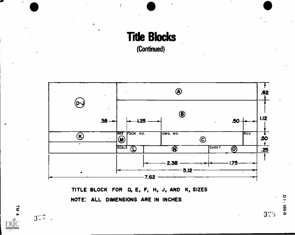
1
4
Title Blocks(Continued)
®
h-I.25
VE-FSCM NO.
, ®DWG. NO.
®
SCAL SHEET ©
I2.38
5.12
1:75 .
TITLE BLOCK FOR D, E, F, H, J, AND K, SIZES
NOTE: ALL DIMENSIONS ARE IN INCHES.
257
A 31)ft.'

Revision Blocks
REVISIONS
ZONE REV DESCRIPTION DATE 4 APPROVED
.50
T-
5.50.88 -91-4-1.00 H
f.25.25
=1_1.25
if
ZONE REY
REVISIONS
DESCRIPTION DATE APPROVED
7.001.00
NOTE: ALL DIMENSIONS ARE IN INCHES
2-5-±
3S:)

r
0 DRAWING SHEET LAYOUTUNIT IV
s%
t
t
ASSIGNMENT SHEET #1--COMPLETE A TITLE BLOCK SHEET
I. Tools and equipment
A. Pencil
B. Drawing sheet
C. Parallel bar or drafting machine
II. Procedure
A. Tape sheet to drowing surface
B. Select correct pencil
C. Compile title block data
D. Letter in information in its proper place
)III. Diagram of the procedur:e
,Psi
D I - 169-B
(NOTE: Instructor should select an appropriate title block to use in this class and
give instructions on filling it out.)
Pictured on Transparencies 3 and 4+are samples of title blocks. Devise one of yoilr
own or select one shown.
.%
)
3') 1...),
P
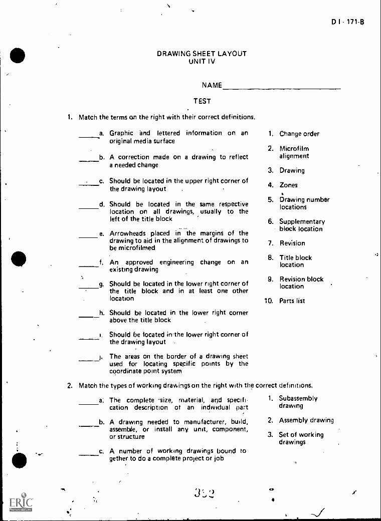
-
DRAWING SHEET LAYOUTUNIT IV
NAME
TEST
1. Match the terms on the right with their correct definitions.
a. Graphic nd lettered information on anoriginal media surface
b. A correction made on a drawing to reflecta needed change
c. Should be located in the upper right corner ofthe drawing layout .
d. Should be located in the same respectivelocation on all drawings, usually to theleft of the title block
... _e. Arrowheads placed in the margins of the
drawing to aid in the alignment of drawings tobe microfilmed
f. An approved engineering change on anexisting drawing
Should be located in the lower right corner ofthe title block and in at least one otherlocation
g.
h. Should be located in the lower right cornerabove the title block
i. Should be located in-the lower right corner ofthe drawing layout ..
The areas on the border of a drawing sheetused for locating specific points by thecoordinate point system
D I - 171-8
1. Change order
2. Microfilmalignment
3. Drawing
4. Zones4
5. Drawing numberlocations
6. Supplementaryblock location
7. Revision
8. Title blocklocation
9. Revision blocklocation
10. Parts list
2. Match the types of working drawings on the right with the correct definitions.
a: The complete .size, material, and specifi-cation description ot an individual part
b. A drawing needed to manufacturer, build,assernbde, or install any. unit, component,or structure
c. A number of working drawings bound together to do a complete project or job
,-..,
3:, 2. ,
I'
1. Subassemblydrawing
2. Assembly drawing
3. Set of workingdrawings
42, .t
,.)

172-8
d. A description of how an object fits intoits working position
e. A description of how several subassembliesand details make up a larger unit
f. A description of how several parts fit togetherin one unit
4. Working drawing
5. Detail drawing $
6. Installationdrawing
3. Match the other types of drawings on the right with their correct definitions.
a. Drawings which are carefully checked foraccuracy before they are sent into the field orinto the shop for fabrication
1. Process drawings
2. ChecIsjoi drawings
Drewings used in the development of experi- or check seI
mental or protbtype designs3. Layout drawings
c. DraAngs of onlyor manufacturingmachine operatora single operation
4. Select the basic informationpriate blanks.
a. Drawing media
b. Scale
, C.
a
one step in a productionassembly which enable ato set up equipment for
needed on a drawing by placing an "X" in the ap
ComPin'y name and address
Revision block
Notes
Approval signature
List 'Of materials
Drafter
Final check
j. Droving number
, k. 'Revision number
I. ToleranceA
rn. Issue date
n Drawing name
o. Date
P. Contract numbers
0.
a.

i.
----........e
1,.
\
A
IL. ). ...
..
D I - 173-13
5. Select the information found in the title block by placing an "X" in the appropri-ate blw-iks.
I
a i
r.
o
-a
1
. a. Material
b. Drawing name%
c. Drafter's name,
d. Part number
e. Checker's name ,.
, -I
N
f. ....Approval signatures .
etg. Contract numbers 1
h. 'Approval by someone in another company-
i. Quantity needed
l. Issue date t 'vet
lf. Date checker completed chedking functionsI
I. Date drafter completed drawing
*Y7 C, s,m. Description subassembly
n. Drawing number
o. Company name and address of manufacturer's number
,
6. Select the information found in the revision block by placing an in the appro-priate blanks.
4.?
a.. Date
b. Tolerance,
c. Approval
d. Zone '''7 .
e. Reason foi revision
f. Description or identification
g. Checker's name
h. Revision number
1. List of materials
(% . ,_,
/r

174-B
7. Select inforMation found in a parts list by placing an "X" in the appropriate blanks.
a. Part number of subassembly
b. Quantity needed
c. Name of item
d. Zone
e. Page number of the total parts lists
f. Assembly list number ,
g. Tolerance
h. Checker's name
i. Write/Cs name
j. Approval signature
k. Date
I. Description of the assembly
m. TreatiMnt
n. Account number if needed for billing purposes
o. Item number of subassembly
p. Description of subassembly
q. Letter designation of drawing size
8. Select information found in supplementary blocks by placing an "X" in the appro-priate blanks.
a. Finish
b. Treatment
c. Quantity needed
d. Material
e. Information covering notes on dimensioning and tolerances
f. Usage and general notes
g. Checker's name
9. Demonstrate the ability to complete a title block sheet.
(NOTE: If this activity has not been accomplished prior to the test, ask your instructorwhen it should be completed.)
)
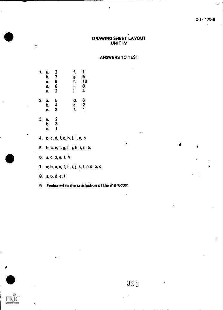
40
a
DRAWING SHEET LAYOUTUNIT IV
ANSWERS TO TEST
1. a. 3 f. 1
b. 7 g. 5c. 9 h. 10d. 6 i. 8e. 2 j. 4
2. a. 5 d. 6b. 4 e. 2C. 3 f. 1
3. a. 2b. 3C. 1
4. b, c, d, f, g, h, j, I, n, o
6. b, c, e, f, g, h, j, k, I, n, o,
6. a, c, d, e, f, h
7. it b, c, e, f, h, i, j, k, I, n,o, p, q..
,
8. a, b, d, e, f
9. Evaluated to.the satisfaction of the instructor
,1
.h
a
D I - 175-8
i

ARCHITECT'S SCALE USAGEUNIT V
UNIT OBJECTIVE,
D I - 177-8
0
After completion of this unit, the student should be able to describe an architect's scale,,listthe seven scale ratios found on an architect's. scale, and read an architect's Wile at variousratios. The student should also be able to meast4e lines accurately using various scale ratios.This knowledge will be evidenced by correctly performing the procedures outlined on theassignment sheets and by scoring 85 percent on the unit test.
SPECIF I ;OBJECT I VES
After completion of this unit, the student should be able to:
1. Match terms related to 'architect's scale usage with their correct definitions.
2. Describe an architect's scale.
3. State the purpose for using a scale.
4. Identify five basic shapes of scales. `
5. List seven scale ratios found on an architect's scale.
6. Select rules for correct scale usage.
7. Interpret 1/16, 1/8, and 1/4 graduations on a full size scale.
8. Calculate and locate 1/32" graduations on a full size scale.
9. Read the architect's Kale at full scale ratio 12" x 1'- 0".
10. Read the architect's scale at the scale ratio 6" ai 1'- 0".
11. Reed the architect's scale at the scale ratio 3" x 1'- 0".
12. Read the architecesscale at the scale ratio 1 1/2" = 1'. 0".
13. Read the architect's scale at the scale ratio 1/4" = 1'. 0".
14. Demonstratenthe ablity to:
a. Interpret 1/16 and 1/32 graduations on a -full size scale.
b. Read the architect's scale at full scale ratio 12" = 1'. 0".
c. Read the architect's scale at the scale ratio 6" x l'- 0".
1 C.0 0.4t..., if i
o

1784
d. Read the architect's scale at the scaleratio 3" 1'. 0".
e. Read the architect's scale at the scale ratio 1 1/2" 1% 0".
f. Measure lines accurately with various scale ratios on an architect's scale.
t
I
.*
-
* / D I - 179-B
ARCHITECT'S SCALE USAGEUNIT V .
f&A
SUGGESTED ACTIVITIES
I. Provide student with objective sheet.
II. Provide student with information and assignment sheets.
III. Make transparencies.
IV. Discuss unit and specific objectives.
V. Discuss information and assignment sheets.
VI. bevelop a displa% of all types of measuring rules, tapes, scales, and related iteinsused in various mkhine and building trades. Include all five types of scales used ina drafting room. Discuss this display in depth with students.
1
VII. Explain why scaling should not be com_pleted on blueprint copies.
Ail I I. Use unit test ai a pre-test to determine prior knowledge of the architect's scaleusage.
I X. " Grve test.
INSTRUCTIONAL MATERIALS
I. Included in this unit:
A. Objective sheet
B. Information sheet
C. Transparencir masters
1. TM 1--Architect's Scale
2. TIV 2- Graduations on a Rule
3. TM 3--Measurements at Scale of 12" = 1'- 0" (Full-size)i
4. TM 4--Measurements at Scale of '6" = fl- 0"(Half-rize)
5. TM 5--Measurements at Scale of 3" = 11- 0" (1/4 size)
6. TM 6--Measurements at Scale of 1 1/2" = l'- 0" (1/8 size)
7. TM 7--Measurements at Scale of 1/4" = l'- 0" (1/48 size)
lf ii' ...)
c
\\"'".......---
a

Ais1.111..ne
Assigninert Sheet 41 litieiiiret 1/16 and 1/32 Graduations On d FullSI/ N'i.t,11 Rule
2 Assiiiirnerit Sheet #2 Re,:d Om Architect's Scali- at Full Scale ,Ratiu12" 1' C''
Assigitment Sheet #3- Read the Architect's S(..ale at the Scale Ratio.6" 11. 0"
4 As-sic:nit-tent Stwer fri Ro:.;t it Architect's Scale at :he Scalr '3atio3.,
1,
5. Assignment Sheet #5.-Read the Architect's Scale at the Scale Ratio1 1/2" = 1' 0"
A
6 Assignment Sheet #6 Wisure Lines Accurately with Vaitous ScaleRutin-, (pi rin Architect's SI ale
-10;i1n::Lut sheets
T.
'.'ialttr C. thdttimiy tom Industry. SouttralZilland, 60473 TheG,10,1116ar Con,r)dny In, 1974
Dy , homas and Spenr Henry.ew I"Y 19022: Macmillan Publuchinq Co Inc , 1968.
I Fi-derick E ci at Terhini iirdy/mq. New York, -;Y 10022.R.ifir:11111q Co 1980
- ;ptil ar 4 Hidsel, .1' Ort.../in am: Design're Liv s LGr (WV HIll Book Con pany, ");9
otaut,,N rt( hflo/dqv Pr& ii Peoria, IL ')1615,Ii; A tir'n't' Co ,111( , 19 13
e?,

,
ti
-.
ARCHITECT'S SCALE USAGEUNIT V
INFORMATION SHEET
I. Terms and definitions
0 I - 181-B
A. Actual size--An object's dimensions, the size it actually is in completed form
/ vrB. Scale--An instrument used as a standard of reference when drawing an
object to a proportional size
C. Draw to scale--Drawing an object at a set proportion such as half its actualsize, one-fourth its actual size, or double its actual size
D. Architecture--Dealing with the design and drawing of public and privatebuildings
E. Graduations--The subdivisions in a scale unit, all of which are equal in size or
length
F. Scale ratio--A relationship between dimension values used to reduce orenlarge the size of an object so that it can be drawn to proportion 4
G. Fraction--A part of a whole, such as 1/2 or 1 /4
H. Full-divided scale--A scale with the basic units subdivided throughout thelength of the scale
I. Open-divided scale--A scale with'only the end unit subdivided into fractionalparts ,1
,
J. NTS--Abbr Niation meaning "not-to-scale"
II. Description of architect's scale--Scale used primarily for drawings of buildings,piping systems, and otherlarge structures which must be drawn to a, reduced scale
to fit on a standard sheet size; it has one full-size scale and ten reduced-size scales
(Transparency 1) f
.
(NOTE: In all of the reduced scales, the major divisions represent feet, and their ,..,subdivisions represent inches and fractions thereof. Thus 3/4" scale means 3/4inch = 1 foot, NOT 3/4 illch * 1 inch.)
III. Purpose of using a scale to draw--Enables objects which are too large or too smallto be drawn to actual size, or be drawn with a standard point of reference con-trolling the relative size of each part
,-,
a
1 ri I41,1,1 I
r,

102-B
INFORMATION SHEET
IV. Basic shapes.of scales
A Triangular
B. Four-bevel '
C One bevel
Two-bevel
E Opposite bevel
<
V Scale ratios found on architect's scale
A
B
C
D
E.
F
C
12" 1' 0" Full size
6:' 11 0" Hal! ;ire
3" 1' 0" 1/4 size
1 I 2" 1' 01 18 size
1" 1' 0" 112 size?
. ,3'3" - 1' 0" 1'16 sqe
1,?" 1' 0" 1 24 sirn
3 8 1' 0- 1 32

rINFORMATION SHEET
I. 1/4" = 1'. 0" -- 1/48 size
J. 3/16", = 1'- 0" 1/64 size
K. 118". 1'. 0" -1/96 size
,L. 3/32"= (5" 1/128 size
VI. Rules for correct scale usage
A. Selettproper scale ratio
B. Scale should lay flat on the surface being measured
C. Scale should be parallel with or on line bilk% measured
D. Do not stick compass or divider points into stale
D I - 183-8
E. Edge of the scale should be protectedtd-prevern damage to its graduationmarks
F. A short dash shouldiwrree rather than a point to mark a distance
. G. If a series of measurementkare to be made on full size scale, do not movescale for each measurement
(NOTE: Set off measurements with scale in one position.)
H. iviake sure that the line ot sight does not create an optical illusion
(NOTE: This could result in an Incorrect measurement.)
VII. How to Interpret 1/16", 1/8" 1/4" and 1/2" graduatidns on a full size scale(Transparency 2)
A. Full tale (12" represents 1'. 0")
1. Sixteen one-sixteenths (16/16) = one inc (1")
z
1111Ill I 11
1
2. Eigh one-eighths 8/8 = oneeighth inch (1/8")ill
III III III
1
inch (1"); two one.sixteenths (2/16) = one.
:j p

184 8
F:FOI,MATIoN SHEET
3. Four one feturtha '(4 4) owl. ineh (1"), fotir one %octeenths t4i16)ono fourth inch (1/4") 1 1
4 i wo one halves (2/2) ,Olh` Inc) 1"). l`killt Ofi0 sixteenths (816)one 1141f inch (1'2") irrrTrlirn:L1
1
_St
5. For 1/32" increments there are two 1/32" in one 1116" and two116" In One 1/8" 1 8 1 16 1 32
B. 1);men+unt, n r-,1,1 iii ts
1 Feet ma, ked th; t't
2, inchrc rnsrked th :s l°1
4'1, F.* t'T I I
I Ii
ow`
3 Fract on; of An (1 4 1 2 5.t ,
(NOTE I)idn 12 wh,s, ose. Int r;yinho, Over12istenes snook; t,cs oo', t 1 'oo rij r e-ht, as in 1' 3".)
VIII How to L,iicul6to ettidl.)catk. 1 32" A ;,,tiof ,% o
A. Fos 1:32" Incren ontt te,v 1 1 16'
8 5ithtract 1 32° 'roil; rh. ,t.,a1 t 11.1 vs,otked ,t:ith to hod the1(31.no, 141 hit" Pre
C Add 1'32" N'o the read.ro,civer the rt'ad;'1(1
-; th to tol ..,ssest 1 16
0 Find the 'aho ;.,111.. 1 1') ind ittpro-...ette thecenter bets,e.-ti toe t,e,
S.

et6
9
INFORMATIPN SIitETI
D I - 18511
E. Mark this approximate center by 'making short dash with a sharp lightlead arAd observe reading
Example; The reading wanted is 11/32"6
.1. Subtract 1/32" which give(10/32 or 5/16"
2. Add 1/32" which gives 12/32 or 3/8"
3. Locaie 5q 6 and 3/13 and approximate center
4. Mark approximate 11/32" point
IX. Read the architect's scale at full scale ratio 12" 1'- 0"
(NOTE: Measurement is made by reading directly from full size scale in inchesand fractions.) (Transpiirency
Example: If the reading Wanted is 2 13/16", start at "0" and determine howmany full inches are between 0 and the point being measured; there are2. Next, determine how manyw 1/16" units are between thelast full inch arid the point being measured; there are 13 1/16" unitsand the measurement is 2 13/16"
210

.1'86 8
*INFORMATION SHEE r
X. Read the architect.$ scdlc at'.the scale ratio 6" ( Transparency 4)
A. When measurrng i glyen line at half size, use Ore full size scale, and multiplyPm full siz e. dhnensinn by 2
B When laying out or drawing a line at hal( i7e, use the full size scale, andd'uflie the full si by 2 to obt:-;:n line lentil].
F. sample: The t;riding is 2 3/16" and the full size scale ,measures 1 13132",so multiply 1 1132" hy 2 giying 2 13/16", the measurement is2 13/16" at half sizt. because at half size, each 1/16" .unit will
.represent 1,8"
Ftill f,17e)
ti...11t.5ize;_ I
.d;
SIZO Scahl
N;UTF Study. this 01.1,4;rdt or riarefullv; as it cit.) be confusing.)
X I Read the ;Jrcilliact's 1*Itto 2" 11 0" ;TrjnsparenLy 5)
A ;Own .t;.(isurti,,,; a ip','f ni it 3 1' , ose the quartet size scale marked
with .1 "3"
B T he subuiy,ded to the riqht ot 2110 lopre8ents one foot ( /2") com-pressed tn actually 3" in length, and it is divided Otto inches, then half
elo.itter ond ..it.ltith inches
Example If the reddinq r, 1'-9 114". lay the scale-so that the 3" 1%0" scale
lays parallel to the 1.ne being measur'ed, then determine how manyfoil feet to -the Ir..ft r)f zero the line eXtPilds (In this example it is1" 0' stt the 1' 0. mark at the left end of the line beingrof:j-oirokt 0001r:for tr t!--ir! r 411 of the zero in the subdivided scalet ;1, 'if .:1 f; ut,* i tw, exarnolt, ot lc 9 1/4"). so
- 4-; 1 1 4"
Hit F.Jurtl,
1 4'
1., 0

INFORMATION SHEET
XII. Read the architect's scale at the scale ratio 1 1/2" z 1'- 0" (Transparency 6)
A. When measuring a given line, at 1 1/2" z 1'- 0" use the 1/8 size scale rirkedwith a "1 1/2"
B. The subdivided unit to the left of zero represents one foot (12") compressedto actually 1 1/2" in length, and is divided into inches, half inches, and guar.,.ter inches
C. Measure full feet to the right of the zero and measure agthing less than 12"in the subdivided unit to the left of zero
Example: If the reading is 2'- 7 3/4", lay the scale so that the 1 1/2"scale lays parallel to the line being measured; determine how manyfull feet to Atte right of zero the line extends fin this example it is2'- 0") then set the 2'- 0" mark at the right.end of the line beingmeasured and refer to the left of the zero in the subdivided stalearea for the inches and fractions (in this example it Is 7 3/4") sothe total length is 2'- 7 3/4"
( One-Eighth Size ) 1 1/2"=110"
XIII. Read the architect's scale at the scale ratio 1/4" = 0" (Transparency 7)
A. When measuring a given line at 1/4" = 1' 0", use the 1/48 size scale marked
with a VA"
B. The subdivided portion to tne right of zero represents one foot (12") com-pressed to,actually 1/4" in length, and is divided into inches
.; 7
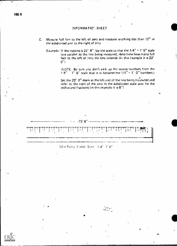
188-8
INFORMATION. SHEET
C. Measure full feet to the left of zero and measure anything less than 12" inthe subdivided unit to the right of zero
Example: If the reading is 23'. 8", lay the scale so that the 1/4" 1' 0" scalelays parallel to the line being measured, determine how many fullfeet to the left of zero the line extends (in this example it is 23'-
If
)NOTE. Be sure you don't pick ap the wrong numbers from the1'8" 1' 0" scale that is in between the 1/4" -= 1 OThumbers.r
Set the 23' 0" mark at the left end of the line being measured andrefer to the right of the zero in the subdivided scale area for theinches and fractions (in this example it is 8")
-23' 8"
17-T1FITTTT I 1 rITT-rj I 'T,.; I I j,-ST 171.1771-41.
A
ft.)-w Forty riuhth 1 4' 1' 0"

DI-1894 I
Architect's Scale
7 -0"00--714" or 91'
ia Size
This is how the Architect's Scale sh
3 Ls 3
_ _ _

--t
Halves
Graduations on a Scale
1 --)
Quarters
Sixteenths
1 e
Eighths
U1.1111111111
1
Thi -Seconds
-.
.1/2i
1/4 3/4
1/8 1 3/8 5/8 I 7/8t t I t3/16 7/16 111/16 115/16
1,16 I 5/16 I 9/16 113/161 Iti 1 1 1 Iti 1 1 I
Graduations Applied to a Rulea
401 ie

Measurements at Scale of 12" r. T-0"
(Ful Size)A
. 324
... 2a. .
4 1 I 65
T
\I
i 1 1 11 1 I -1 TT1-
161 I 1 2. r:
3 4 5
- 41.)1
,
o
. a

..,
:
IC ,
Measurements at Scale of 6"ii T-0"
Ma if-Sizel i
81
4
a
434
s
A
,.
Measurements at Scab of 6" =
c
.,

Mftsurements atSage
illuanerftsizei
4J7

1
Measuremmits at Scale of,112": VO"
(1/8 Size)
. 1%1r
1019.
3'-0"
b
4
,
One-Eighth Scab Si" = 1%0%
0

4
,
4
T.
: 4 11
Measurements at Scale of 1/41' a T-0"
(Y48 Size)
: .
..
9
...
,
24'-0"
.,1481 1 52
2256
IR
17-9"
i 4re- 3'-2"
40 I 641. n 1 76 I C I Els I92
1
16 14 1 10 8 -6 4 2 0
4.
A
.,

i
ARCHITECT'S SCALE USAGEUNIT V
ASSIGNMENT SHEET #1--INTERPRET 1/16 AND 1/32 GRADUATIONS .
ON A FULL SIZE METAL RULE
D I - 2034
Directions: Reed the measurements shown below at full size by reading from end of rule atleft to points indicated by extension lines.
IREAM(
'1IIIIIII111911111111IplypillypiliThitilill
11 21 31 41 51II
2.
4.
5.
READING
1.
furl w I i ill!! 11 i I II I I 11 II I I II I pp' T
READING
2
Tilifillippil2
'HI IIIIIIIT P11111111111111111 lil ilili III
31 41 51
READING
3
1 .
1111t 11 lif III i I III' 1 1Ilif [1 mill IIIIIIIII3
IIIIIIIII1(111111111111111111111
41 51
READING
_ 1
wiliriliT IITTITI1111111111101111111iiiiiiiiiitirifi 11111911111111111111113
1 21 31 4' 511
5.
4.
..
OM
READING
6 1214202426 4 12142024261 e 2
4 II 12142024263 4 6 1214202426
4
a
4 6 1214202426
5
6
.

204-8
7.
a.
9.
10.
tprIvirprilivir,1 III
1
ASSIGNMENT SHEET #1
READING
A 1216 2024 28
try-111,4I 1
1216202428 A 11 121'02024283 4
4 121112024215
r--- READING
7.
1 12162024 2111
4 1216 2024 211
24 1216202421 1216202422
44 12111202420
5
READING
a.
4 8 121620242R 4 81216202428 i 4 1216202428 4 8 1216202428 4 11 1218 2024214
4
READING
9. f
i.111!.i 111111,1111.11111111111.01,1,111111111111111 bfill!11111111111111p18r1111'I II 1111
9 11/6202428 1 4 8 12192C24 28 4 8 12162024A I 4 I 17162074281 2 3 4
,11111111111111111111111111
4 1242024205
Ito
10.
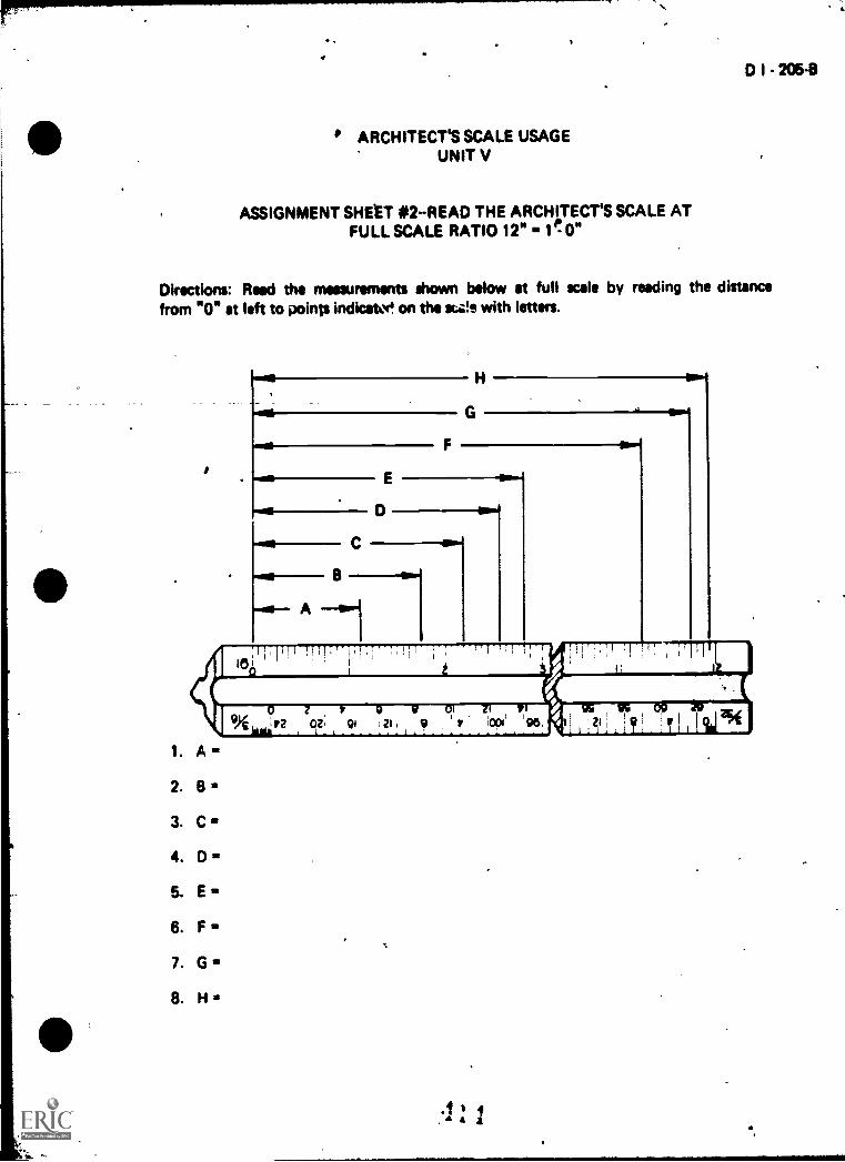
D I - 206-8
ARCHITECT'S SCALE USAGEUNIT V
ASSIGNMENT SHEET #2-READ THE ARCHITECT'S SCALE ATFULL SCALE RATIO 12" 1t0"
Directions: Reed the measurements shown below at full scale by reading the distancefrom "0" at left to points indica& on the sta!e with letters.
Noe
-NI-- A ---.1
TITIITH UlTiT1,77,
9,9 42 07, I I t ,
0 7 r 9 v 01 zi ri
0 1
t t 1 ti
1. Am
2. .3. C
4. D
5. E
6. F
7. G
8. H
1,111T1119i125)SS og /to

D I - 2074
ARCHITECT'S SCALE USAGEUNIT V
ASSIGNMENT SHOT #3-READ THE ARCHITECT'SSCALE AT THE SCALE RATIO 8"
Directions: Read the measurements shown below at half scale by reeding the distancefrom "0" at left to points indicated on the scale with letters.
D 7C
B
fro- A --1
1. A
2. 8
3. C
4. D
5. E-
6. F
7. G
8. H
4 z
11)

1
D I 2094
ARCHITECT'S SCALE USAGEUNIT V
ASSIGNMENT SHEET #4-READ THE ARCHITECT'S SCALEAT THE SCALE RATIOY . 1' ON
Directions: Reed the measurements shown below .et helf scale by reeding the distance
from "Os et left to points indicated on the scale with letters. ,
___ H
wool G
I
1. A.
2. B.
1 C.& D.a E.6.,F=
7. G.
a H.
ilz6
t
-
,

D I - 2114
ARCHITECT'S SCALE USAGEUNIT V
ASSIGNMENT SHEET #5--READ THE ARCHITECT'S SCALEAT THE SCALE RATIO 1 1/2" 11- 0"
Directions: Read measurements shown below at half scale by reedirig the distance froMat right to points indicated on tho scale with letters.
1. A =
2. 13 =
3. C =
4. 0 =
5. E =
6. F =
7. G
41

an
ARCHITECT'S SCALE USAGEUNIT V
ASSIGNMENT SHEET 06:MEASURE LINES ACCURATELY WITH VARIOUSSCALE RATIOS ON AN ARCHITECT% SCALE
D I - 21311
Directions: Measure the lines A through .1 to the scale heading each column in the table.Print the scale readings hi the appropriate spew in the tebie.
Example: Measure line A to the 3/32" I s- 0". A reeding of 63'. 6" is obtaintd.This dimension under the 3/32" I s- ON column and opposite theletter A. Use guide lines for 1/8" lettering.
(NOTE: Reedings must be accurate Or they will he conskierdo wrong, end lettering meetbe Met and correct.)
4
4

214-11
4
ASSIGNMENT SHEET #6
LINE 3/32" .110"
1/8" .1LO"
1/4" 1.r gO"
3/8" -11-0"
1/2" ,, 1Io"
1 1/2" .go"
3"go" .
A
s,
--._
E
. .
,
.
. .
,
,
,
,
Its
,.

ARCHITECT'S SCALE USAGEUNIT V
ANSWERS TO ASSIGNMENT SHEETS
111.
Assignment Sheet #1
1. 3 3/16"
2. 3 15/16"
3. 2 5/16"
4. 4 3/8"
5. 3 9/16"
6. 3 31/32"
7. 3 14/32" or 7/16"
6. 4 5/32"
9. 3 8/32" or 1/4"
10. 4 15/32"
Assignment Sheet *2
1. A = 1 1/8"
2. B = 1 3/4"
3. C = 2 3/16"
4. D = 2 9/16"
5. E 2 13/16"
6. F = 11 1/4"
7. G = 11 3/4"
8. H 11 15/16"

..
Assigrw.nom Shoot *3
%
1. A a 21/4"
2. 8 a 3 1/2"
3. C43/8"
4. 0 5 18"
5 5/r
22 1/2" or 11, 10 1/2"
7. G a 23 1/2" or 1% 11 1/2"
. 8.. H a 23 7/8" Or 1% 11 7/8"
A:segment Sheet *4
1. A=1"
2. s - 1 1 /2"'
3. C = 2"
, 4. 0 a 3"
5. E a 3 3/4"
6. F a 6"
7. G = 8 1 /4"
a H - 9"
Assignment Shoot *5
:
f
1. A - 1" 1
2. a 1. 1 314"
3. C = 3"
4. D a 6 1/2"
5. E - 8 1/4"
6. F a 11"41 6 a 1
7. G a 12" or 1 . 0" .... t
( \
1

.
Assignment Short 08I
,
LINE
_
3/32"11-0"
118"1.1-0"
1/4"1L0"
3/8"11-0"
1/2"1=0"
1 1/2"12-0"
3"-lid"
A 8410" 48'4" 24'-4" 16-244" 124.2" 4-046" 7-3/4"i.
e
.51-8" 38'-g" 19-4" 12401/1" 9-746" 3-21/2" , V-rA"
C 42'-5" 31-10" 15%11" 10'-714" T-111/2" 2'-746" 1'-3.1i"
0 47-0" 35-214" 17-7ve 11'43/4" 6-914"a
2-113/4" 1'-5%"
E 57-11" 43-5" 21-9" 14.5,6" 10'-10ye 3-71/s" 1-9114",
F 36-7' 27.5" 1341/2" 9-1;4" 6-101/4" 2-33/4" 1-13/4"
G 24.7's
18'-5" 9-3" 81-146" 4'.71/2" 1 '-7" 0%91/4",,
H 14%4" 10.9" 5'-41/2" 3-7" 241/4" 0%103/4" 0-546"
I T-9" 5-10" 2-1.1" 1%11" 1.51/2" 0-516" 0'.2%"
.1 2'4" 2'4" 1'4" 0'4" 0'4" 0%2" 0%1"
I
J
!I ft.
s
I

ARCHITECT'S SCALE USAGEUNIT V
NAME
TEST
1. Match the terms on the right with their COrreCt definiti .
a. An obfen's dimensions, the size it actually is
in completed form
b. An instrument used as a standard of referencewhen drewie9 an obict to a Proportional size
C. Drawing an object at a setooportion such ashalf its actual size, one-fourth its actual .size,or double its actual size
d. Dealing with the design and drawing ofpublic arld priyate buildings
e. The subdivisions in a scale unit, all of whichare equal in size or length
f. A relationship between dimensignal valuesused to reduce or enlarge the size of an objectso that it can be drawn to proportion
g. A part of a whole, such as 1/2 or 1/4
h. A scale with the basic units sUbdividedthroughout the length of the scale
i. A scale with only. the end unit subdivid-ed into fractional parts
j. Abbreviation meaning "not-to-scale"
2. Describe an arcliitect's scale.
3. State the purpose for using a scale.
1. Graduations
2. Open dividedKale
3: kection
4. Architecture
5. Actual size
8. Full-divided.scale
7. NTS
8. Scaleratio
9. Draw toscale
.10. Scale
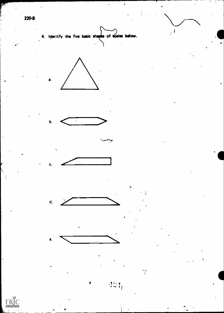
4. Identify the five basic
a.
b. < . >\ _,.,
d.
es below.
4..... 1 /
i

5. List seven scale ratios found on an architect's scale.
a.
tr
C.
d.
e. .
f.
9.
6. Select rules for correct scale usage by placing an "X" in the appropriate blanks.
a. Select proper scale ratio
b. Scale should be at a 30 angle to the line being measured
c. Scales can be used as a c -ting edge
d. Scaie should lay flat on the surface being measured
e. A short daih should be made rather than a point to mark a distance
f. Stick compass or divider points into scale to set instruments
g. Edge of the scale should be protected to prevent damage to its gradua-tion marks
h. If a series of measurements ar to be made on the full size scale, do notmove scale for each measurement
i. Make sure that the line of sight does not create an optical illusion
7. Interpret 1/16, 1/8 and 1/4 graduations on full size scale shown below:.. a. ... b.
i
9GI 21 tf 1 9G
I I 12
72 2 ,4 2 q r DO 96 21 9
.-a. b. c. d. e.
41
4.
1..e...d.
1
alg h
Li

F181.1118.411111011111
222-8
8. Calculate and locate 1/32" graduations on the full size scale shown below hy markingeach dimension with a 1/8" dash and labeling the point with the correct dimension.
a. 1 5/32"
b. 2 21/32"
c. 11 13/32"
.,
9. Read
a.
the architect's scale at full scale ratio 12" = 1'-
b.
0"
c.
....1.
c..0-- ba...
!2
-77'1.4 :' Ot
i
1.-
,... IQe t-,
2()
10. Read the architect's scale at the scale ratio 6" . 1 '- 0".
I-
a b.
T
C.
[1 b.----1I
,
C.
4,,... ..,,

0 1 - 223-8
11. Read the architect's scale at the scale ratio 3" = 0".
9. b. 1811...
12. Read the architect's scale at the scale ratio 1 1/2" = 0".
a..
b..
C.
rIy2 ,,, , 31 01
13. Read the architect's scale at the scale ratio 1/4" = 0".
a.
b.
C.

224-13
14. Demonstrate the ability to:
..a. Interpret 1/16 and 1/32 graduations on a full size wale.
b. Read the architect's wale at full scale ratio 12" = 1% 0".
c. Read the irchiteces scale at the scale ratio 6" = l' 0".
d Read the architect's scale at the scale ratio 3" = l' 0".
e. Read the architect's scale at the scale ratio 1 1/2" = l'- 0".
f. Measure lines accurately with various scaie ratios on an architect's scale;,
(NOTE: If these activities have not been accomplished prior to the test, ask yourinstructor when they should be completed.)
il 4 ' ' .A ... -J
_

..
ARCHITECT'S SCALE USAGEUNIT V
ANSWE RS TO TEST
1. a.
b.c.d.e.
510941
f.
9-h.i.
j-
8362
7
2. Description should include: scale used primarily for drawings of buildings, pipingsystems and other large structures which must be drawn to a reduced scale to fit on astandard sheet size; it has one full-size scale and ten reduced-size scales
3. Enables objects which are too large or too small to be drawn to actual size, or be drawnwith a standard ppint of reference controlling the relative size of each part
4. a. Triangular d. Two-bevelb. Four-bevel e. .Opposite-bevelc. -One-bevel
5. Any seven of the following:
A.
B.
C.
12" = V- 0" - Full size
6" = 1'- 0" - Half size
3'1.= l'- 0" - 1/4 size
D. 1 1/2" = 1'- 0" -- 1/8 size
E. 1" = r- 0" 1/12 size
F. 3/4" = 1'- 0" 1/16 size
G. 1/2" = 1'- 0" 1/24 size
H. 3/8" = 1'. 0" 1/32 size
I. 1/4" = r- 0" 1/48 size
.1. 3/16" = r- 0" -- 1/64 size
K. 1/8"= 1'. 0" -1/96 size
L. 3/32"= r- 0" 1/128 size
41 4 4 4 Ia"
4a.

6. a, d, e.g. h, i
7. a. 10 3/4"b. 2 13/16"c. 1 13/32"d. 1/16"0. 1/8"
8.
1
1 5/32.
,
11 13/32
9., a. 1 9/16"b. 2 11/16"c. 11 3/16"
10. a. 1"b. 2 9/16"c. 5 3/8"
11. a. 11- 11 1/2"b. V- 9 1/4"C. s"
12. a. 4"b. 6 1/2"c. 2'- 6 1/2"
13. a. 3"b. 5'. 6"c. 43'. 10"
,
..
14. Evaluated to the satisfaction of the instructor

,D I - 227-It
CIVIL ENGINEER'S SCALE USAGE* UNIT VI
UNIT OBJECTIVE
After completion of this unit, the student should be able to describe a civil engineer's scale,select rules for its correct usage, and interpret scale graduations. The student should SW beable to mod a civil engineer's scale in various scale ratios. This knowledge will be evidencedby correctly performing the procedures outlined on the assignment sheets and by scoring 85percent on the unit test.
SPECIFIC OBJECTIVES
After completion of this unit, the student should be able to:
1. Match terms related to civil engineer's scale usage with their correct detnitions.
2. Describe a civil engineer's scale.
3. State the purpose for using a civil engineering scale.
4. Identify five basic shapes of scales.
5. Select rules for correct scale usage.
6. List scale diviskins that tairfetrifd on a civil engineer's scale.
7. Interpret scale graduations found on a civil engineer's scale.
8. Demonstrate the ability to:
a. Find the civil engineer's scale using a scale ratio of 1" 1' -0".
b. Read the civil engineer's !Cale using a scale ratio of 1" 20
c. Reed the civil engineer's scale using a scale ratio of 1" 30
d. Read the civil engineer's scale using a scale ratio of 1" 40
e. Resd the civil engineer's scale using a scale ratio of 1" 50
f. Read the civil engineer's scale using a scale ratio of 1" 60 *.
g. Measure lines accurately with various scale ratios on a civil engineer's scale.
'1 kr411')

D 1 - 2294
CIVIL ENGINEER'S SCALE USAGEUNIT VI
SUGGESTED ACTIVITIES
I. Prade student with objective sheet.
II. Provide student with information and assighment sheets.
III. Make transparencies.
IV. Discuss unit and specific objectives.
V. Discuss information and assignment sheets.
VI. Develop a display of all types of measuring rules, tapes, scales, and related items
used in various machine and building trades. Include all five types of scales used in
a drafting room. Discuss this display in depth with students.
VII. Invite resource person to attend class and discuss use and types of scales.
VIII. Lead discussion on the advantages and disadvantages of different types of scales.
1)4. Provide problems for the students to use in practicing using the engineer's scale.
X. Give test.
INSTRUCTIONAL MATERIALS
I. Included in this unit:
A. Objective sheet
B. Information sheet
C. Transparency masters
1. TM 1-Civil Engineer's Scale
2. TM 2Civil Engineer's Scale (Continued)
D. Assignment sheets
1. Assignment Sheet #1 -Read the Civii Enginecr's Scale Using a ScaleRatio of 1" = 1' -0"
2. Assignment Sheet #2- Read the Civil Engineer's Scale Using a Scale
Ratio of 1" = 20'

3. Assignment Sheet #3--Read the Civil C. cur's S'Ale Using a Sra'eRatio of 1" = 30'
4. Assignment Sheet #4--Read the Civil r oneer's Scale Using a ScaleRatio of 1" 40'
F. Assignment Sheet #6--Read the Civil 'leer's Scale Using SCct le
Ratio of 1" 50'
6. Assignment Sheet #6--Read the Civi: F ,i,ur's Scale Using a ScaleRatio of 1" 60'
7. Assiganent Sheet #7-Measure Ln ,.ttliy with Various ScaleRatios on a Civil Engineer's Scale
E. Answers to assignment sheets
F. Test
G. Answers to test
I. References:
A. Brown, Walter C. Drafting for IndustryGoodheart-Willcox Company, Inc., 1974.
8 Dygdon, John Thomas and Henry CecilNew York, NY 10022: Macmillan Publishing
C Giesecke, Frederick E., et Technic., !,Macmillan Publishing Cj, Inc.:, 1980.
D. Jensen Cecil and Jay Helsel Engineering )-NY. Gregg Division/McGraw Hill Book Cor,,:
Holland, IL 60473: The
alsic Technical Drawing.we. , 1968.
New Yoilik NI ,10022.
Design. New Yolk,!279
E Spence William P. Drafting Technology t,, Peoria, IL 6115.Chas, A. Bennett Co . Inc., 1973.
0

CIVIL ENGINEER'S SCALE USAGEUNIT VI
\
INFORMATION SHEET
I. Terms and definitions
ro 0 I -1314
A. Actual size--An object's actual dimensions, the size it actually is in com-pleted form
B. Scale--An instrument used as a standard of reference when drawing anobject to a proportional size
C. Draw to scale-Drawing an object at some set proportion such as half itsactual size, one fourth its actual size, or double its actual size
D. Civil engineering-Design and construction of public works, transportationsystems, environmental systems, and other systems
E. Graduations-The subdivisions in a scale unit,all of Which are equal in size orlength
, .
F. Scale ratio--A relationship betkeeri dimensional values used to reduceor enlarge the size of an object so that it can be drawn
G. FractionA part of a whole, such as 1/2 or 1/4.
H. Full-divided scale--A scale with the bilic units subdivided throughout thelength of the scale (
, .
II. Description of civil engineer's scale-Scale used for civil engineering work; it is
graduated in units of one ;nch divided into 10, 20, 30, 40, 50, and 60 parts(Transparencies 1 and 2)
(NOTE: It is used in drawing maps to scales of 1" = 50', 1" = 500, 1" = 5 miles,etc.) .
III. Purpose for using a civil engineer's scaleTo provide a standard of reference that. is needed when drawing civil projects
(NOTE: It allows areas and objects that are too large to be drawn actual size to bedrawn to a usable proportion.)
/ 1 ' . 44 .
tf

232 8
INFORMATION SHEET
&WC shapes of scales
A. Triangular
8 Four bevel
C. One bevel
D rwo bevel
E Oppos te bevel
I a .3, a 4'
sr ft i,t.);wr LI' 0
(:!1 t bf n'l
j" 1t4 i Pd to, cn en re be.n I measured
t.
st.

4111.INFORMATION SHEET
D - 2336
D. Do nt5I stick compass or divider points into scale
E. Protect the edge of the scale to prevent damage to its graduation marks
F. Make a short dash rather than a point to -mark a distance
G. If a series of measurements are to be made on full size scale, do not move
scale for each measurement, but set off measurements with scale in one
position
H. Make sure that the eye's line of sight does not create en optical illusion and
thus an incorrect measurement
VI. Scale divisions found on an engineer's scale
A. 10 scale--1" subdivided in 10 parts
B. 20 scale-1" subdivided in 20 parts
C. 30 scale 1" subdivrled in 30 parts
D. 40 scale--1" 4crivided in 40 parts
E. 50 scale -1" subdivided in 50 parts
F. 60 scale--1" subdivided in 60 parts
VII. How to interpret graduations on the civil engineer's scale
CI
A. 1" = scale ratio
1. Measurement is made by reading directly from the full size scalemarked 10
2. This is a full divided scale with each indi divided into 10 units of 1/10inch
(NOTE: Pits scale can be used for various rattos, such as 1" = 1',
1" = 10', 1" 100', or 1" = 1,000'.)
Example. On the 1" = l scale ratio, ea ch diyision represents1/10 of a foot, so a line containing 10 bnits Would ix10/10 or 1' long, on the 1" = 100' scale ratio, each'division represents 1/10 of 100', so each division is10' long
,1 .

234 B
INFORNIA7 ION ;;IiF
I
i'v
lo,(1
!fl
I = !0.0
,1
8 1" 20 wok. rdt.10
1 Meiclut(ment () tr 0 mdlked 20
2 Th"., s a.full ccoh' h oo ci .:.to 20 units of 1'20 inch
'NOTE. Tn.", ',caw c;..n) uNon r stICIi cis 1" 20, 1" = 200',or 1" 2000' )
Ex impip -On thi 2')' sTrm woresentc 1/20of 20' o lin,. A is23' If`rIfi ;);1 It 1 t:ch div;sion rope
1/20 ,1 2C):1' 0: .n ,t,s,t,nli.ns 50B :30{)
_ _ . 23.
500' " AT 2C)0' LENGTH
rry 1TP p I I IF, T.T7-711177-71.77.7' I
20 0 5
Pt. 91, Vt. litS*
.11 .1, :
.3'

INFOFIMATIO SHEET
1" is 30' scale
D - 23543
1. Measurement is made by reading directly from the scale marked 30
2. This is a full divided scale with each inch divided into 30 units of 1/30inch
(NOTE: This stale can be used for various ratios such as 1" 30',1" a 300', 1" a 3,000'1
Example: On the 1" 30' scale ratio, each division represents1/30,0 30' or one foot, so since it contains 42 units,line A is 42' long; on the 1" a 300' scale ratio, eachdivision represents 1/30 or 300' or ten feet, so sinceit contains 55 units, line B is 550' long
A
550'
42'
l" 300'
I" 30'
30 0 I 2 r3 4 6
D. 1" a 40' scale ratio
1. Measurement is made by reading directly from the scale marked 40
2. This is a full divided scale with each inch divided into 40 units of 1/40inch
(NOTE: This scale can be used for various ratios such as 1" = 40',1" a 400', or 1" a 4,000'.)
Example: On the 1" = 40' scale ratio, each division represents1/40 of 40' or one foot, so since it contains 10 units,line A is 10' long; on the 1" = 400' scale ratio, eachdivision represents 1/40 of 400' or ten feet, so since Itcontains 50 units, line B is 500' long

211i B
r\J E
r- 4001
A- h-10,
4(1i
2 4 6 8
I
)7 r
tP3 EZ ZE IZ 03lii 1111
pA 41.- AI
1,
ctly from fte scale marked 50
divic;ed ;nto 50 rwits of 150
f Ir f,ii ,i)tis ratios stIL'i 1'. 50 1'
1 0 ',col- rdtio, ecrcn div s on represents(); ./1 s4ice !t contains 65 units,
'Irl t!'" 500 scale rata, each'30 n bUO. or ten f.-et, so since it
! s 1,000' :ow;
I":500'
59'
A ,

r F. 1" = 60' scale
a
D I - 237-B
INFORMATION SHEET
1. Measurement ic made by reading directly from the scale marked 60
2. This is a full divided scale with each inch divided ,nto 60 units of 1/60inch
(NOTE: This scale can be used for various ratios such as 1" = 60',1" = 600, l'' -- 6,000' I
Example On the 1" '-=, 60 scale ratio, each division represents1/60 of 60' or o,ne foot, so since it contains 25 units,line A is 25' long, on the 1" = 600' scale ratio, eachdivision represents 1/60 or 600' or ten feet, so since itcontdIns 110 units, line B is 1,100 long
09 9G 9G pG ag ,s ,og 90o
11 Isioliadmislieridiliffilliiiiiitioilitimini dilifitImii

-4C.. A 12
4 11
Civil Engineer's Scale
0111111111111111111IF1
1 I 2
I 11111111111111,11111'11,IIIii110 II 12
G 1 V £ Z I ?OZinpluitImilimhililtnIIIIIIIIIIIIIIIIhaii
Examples for Reading
This scale can be used to reada
IP..
1.01-0-
-. 10.0' 0-
tiwir
I" is I.0'
in a 10.0
I" ss 100.0
I111111i111111112

&
ChM Engineer's Scab(Continued)
300 2 4 6
11111111 1,11F111111111111111111111111r1:11 11 0,111 1
EL 09
IH=50',..
,
IH= 40'-.......4.
50.0' _
r10.0.
400 2 4
i
D 1 - 2414
iP2 CZ ZZ 1Z IZ
111111111111111111111111111,11LIIIImilmillin
100.0'-- ---.-10.01
,.,p,79,,717,10 2 4 6 6 10 12 14
Ilez 60'
1
9t tf 2£ Of
lil, kl.1,11,1L ,..1111.1...1..l.1 a 1 11 k Ililli..1111)11,1illi kJ A1111.111"11
4 4 1
,
TM 2

:
0 I - 243-11
CIVIL ENGINEER'S SCALE USAGEUNIT VI
ASSIGNMENT SHEET#1--READ THE CIVIL ENGINEER'S SCALEUSING SCALE RATIO OF 1" = 1' -0"
Directions: Read the measuremints shown below at 1" = 1' -0" scale reading the distancefrom 0 at left to points indicated on the scale. Place the correct measurements in the blanksbelow the scale.
,i,
[*".. 1
C.
D.
E.
11111111111 11111111110 0
I
I I2
Ion
WWII I3
-4. D =
5. .E =
,4 4
A

D I - 245:8
CIVIL ENGINEER'S SCALE USAGEUNIT VI
ASSIGNMENT SHEET #2-READ THE CIVIL ENGINEERI.S SCALEUSING SCALE RATIO OF 1 u = 20'
Directions: Read the following scale from distance at left to points indicated. Place thecorrect measurements in the blanks below the scale.
1. A=
2. B =
3. C =
1,
-
,
. 4 4,1

0 CIVIL ENGINEER'S SCALE USAGEUNIT VI
6
D I - 247-6
ASSIGNMENT SHEET #3READ THE CIVIL ENGINEER'S SCALEUSING SCALE RATIO OF 1" = 30'
o
Directions: Read the measurements shown below at 1" = 30' scale readinii the distancefrom 0 at left to points indicated on the scale. Place the correct measurements in the blanksbelow the scale.
/
_
-,.
30
A.
B.
C.
D.
E.
4
10 12 14 16
Cl. OL e9 09 OS 9S tS CS oc et et tt et
1. A =
2 =. 3
3. C =
4. D --
5. E =

CIVIL ENGINEER'S SCALE USAGEUNIT VI
D I - 249-8
ASSIGNMENT SHEET ;IA-READ THE CIVIL ENGINEER'S SCALEUSING SCALE RATIO OF 1" . 40'
I.
Directions: Read the measurements shown below at 1" . 40 scale reading the distance,
from 0 at left t9 points indicated on the scale. Place the correct measurements in the blanksbelow the scale.'
1. A =
2. 8 =
3. C i
A. D i
5. E i
,2 f2 22, 12 02
Luillitliitillit111111111ntillultittItiatiltil
i

p.
D I - 251-8
CIVIL ENGINEER'S SCALE USAGEUNIT VI .
ASSIGNMENT SHEET #5READ THE CIVIL ENGINEER'S SCALEUSING SCALE RATIO OF 1" I. 50'
Directions: Read the measurements shown below at 1" z 50' scale reading the distancefrom 0 ats left to points indicated on the scale. Place the correct measurements in the blanksbelow the scale.
1. A z
2. B
3. C =
4. D
5. E
,444 :

D I - 263-11
CIVIL ENGINEER'S SCALE USAGEUNIT VI
ASSIGNMENT SHEET #6--READ THE CIVIL ENGINEER'S SCALEUSING SCALE RATIO OF 1" = 60'
Directions: Reed the measurements shown below at 1" 60' scale reading the distancefrom 0 at left to points indicated on the scale. Place the correct measurements in the blanksbelow the scale. e'
1. A =
2. B =
3. C =
4. 0 =
5. E =
,
/
/r
///
/
I
1
(4,
4 4 . )

D I - 255-8
CIVIL ENGINEER'S SCALE U$AGE. UNIT VI
ASSIaNMENT SHEET #7--MEASURE LINES ACCURATELY WITHVARIOUS SCALE RATIOS ON A CIVIL ENGINEER'S SCALE
Directions: Measure the lines A through F to the scale ratio heading each column in thetable. Letter the scale readings in the appropriate space in table using guidelines for 1/8"lettering.
Example: On a 1" = 10' scale ratio, lin* A would be 55' long; this figure should belettered uncle!. the 1" = 10' column opposite letter A.
A
A
7.!
1"=10' 1"= 20" 1"=300' 1"=40' 1"=500' 1"=60' 111=10

, D I - 257-B
1-..
Assignment Sheet #1
1. A7 .1'
2. B = 1.35'%
3. C = 3'
4. D = 8.7'
5.--£..z 10'P
1
Assignment Sheet #2 ,
CIVIL ENGINEER'S SCALE USAGEUNIT VI
ANSWERS TO ASSIGNMENT SHEETS
-
1. A = 20'
2. 8 = 60'
1 C = 70'
0 AssignMent Sheet #3
,
I
I
1.1
1. A = 10'
2. 8 = 52'
3. C = 90'
4.
5. E = 150'
1......Assignment Sheet #4
1. A = 9'
2. B = 37'4
3. C = 57'
4. D = 70' :7....."---.,
5. E = 86',

258-8
Assignment Sheet #5
1 A = 10'
2. B = 42'
3. C 75'
4. Dr 107'
5. E 140'
Assignment Sheet #6
1. A = 12'
2. B = 72'
3. C 90'
4 D 117'
5 E 141'
Assignment Sheet #7
1"=10 1":= 20" 1"=300' 11'40' 1"=500' 1"=60' 1%10 MILES
44' 88' 1320' 176' 2200' 264' 44 miles
37' 74' 1110' 148' 1850' 222' 37 miles
C 31' \ 62' 930' 124' 1550' 186' 31 miles_f
0 42' 84' 1260' 168' 2100' 252' 42 miles
E 12' 24' 360' 48' 600' 72' 12 miles-- 1- i
30' 60' 900' 120' 1500' 1 180' 30 miles

e
CIVIL ENGINEER'S SCALE USAGEUNIT VI
NAME
D I - 259-8
TEST
1. Match the terms on the right witti the correct definitions.
a. An object's ktual dimensions, the size itactually is in completed form
b. An ,instrument used as a standard of referencewhen drawing an object to a proportional size
c. Drawing an object at some set proportionsuch as half its actual size, one fourth its ac-tual size, or double its actual size
d. Design and constkuction of public works, trans-portation systems, environmental systems, andother systems
,
,
---, e. The subdivisio s in a unit all of which areequal in size or length
1
f. A relationship \ between dimensional valuesused to reduce qr enlarge the size of an objectso that it can be drawn
A part of a whole\ such as 1/2 or 1/4g.\
\
h. A scale with the basic units subdividedthroughout the lensih of the scale
\
2 Describe a civil engineer's scale.
I
a
, 1 ' iArO r
a
1.
2.
3.
4.
5.
6.
Fraction
Graduations
Scale
Civil engineering
Scale ratio
Full-dividedscale
7. Draw to scale
8. Actual size

260-8\ ,\3. Describe the purpose for using a civil engineer's scale.
4. Identify the five shapes of scales pictured below,
a
b
c
d
e
Z\
-__1.7.

D I - 261-8
.7
5. Select the rules for correct scale usage by placing an "X" in the appropriate blanks.
a. Select proper scale ratio
b. Scale should be at a 30 r angle to the line being measured
c. Scales can be id as a cutting edge
d. Scale should lay/flat 8n the surface being measured
e. Make a short dash rather than a point to mark a distance
f. Stick compass or divider points into scale to set instruments
g. Protect the edge of the scale to prevent damage to its graduation marks
h. If a series of measurements are to be made on the full size scale, do not movescale for each measurement, but set off measurements with scale in oneposition
I. Make sure that the eye's line of sight does not create an optical illusion and
thus an incorrect measurement
6. List six scale divisions that are found on a civil engineer's scale.
a.
b.
7. Interpret graduations on a civil engineer's scale.
a. 1" = 10'
1)
2)
"OM-- 2) loo
I 0 2
09r Ri i"; `t H1

262-13
b 1" 20'
1)
1
1Milli111111Iilllil,ITTI11,11y111111111:11 HMI
20 0 3
kit Pt IP (It af 9
tiulatillitiltiliI1111,11,,,,L,LA:11111,.11,JuluiLd.1111,41
1" 30' 2)
1)
t 1
1)
1'' 40'i
T; 7111 11,10 711T1,11I111111111,11111,,
1 1 I
4 a
1̀, I

e.
f. = 60'
21,
8. Demonstrate the ability to:
a Read the civil engineer's scale using a scale ratio of 1" =1'
Read the civil engineer's scale using a scale ratio of 1" = 20'.
c. Read the civil engineer's scale using a scale ratio of 1" = 30'.
Read the civil engineer's scale using a scai ratio of 1" = 40'.
e. Road the civil engineer's scale using a scale ratio of 1" = 50'.
f. Read the civil engineer's scale using a scale ratio of 1" = 60'.
g.
D I - 263-B
tiA
Measure lines accurately with various scale ratios on a civil engineer's scale.
(NOTE. If these activities have not been accomplished prior to the test, ask yourinstructor when they should be completed.) -
j

CIVIL ENGINEER'S SCALE USAGEUNIT VI
ANSWE RS TO TEST
1. a. 8 e. 2b. 3 f. 5c. 7 9. 1
d. 4 h. 6
2. Description should include:
D I 265-$
Scale used for civil engineering work; it is graduated in units of one inch divided into10, 20, 30, 40, 50, and 60 parts
3. To provide a standard of reference that is needed when drawing civil projects
4. a. Triangularb. Four-bevelc. One-beveld. Two-bevel ae. Opposite-bevel
5. a, d, e, g, h, i ,
6. a. 10 scale--1" subdivided in 10 parts
b. 20 scale--1" subdivided in 20 parts
c. 30 scale- 1" subdivided in 30 parts
d. 40 scale--1" subdivided in 40 parts
e. 50 scale--1" subdivided in 50 parts
f. 60 scale- 1" subdivided in 60 parts
7. ' a. .1" = 10'1) 10'2) 100'
b. 1" - 20'1) 10'2) 50'
c 1" = 300'1) 100'2) 500'
li 'A I 4 .....
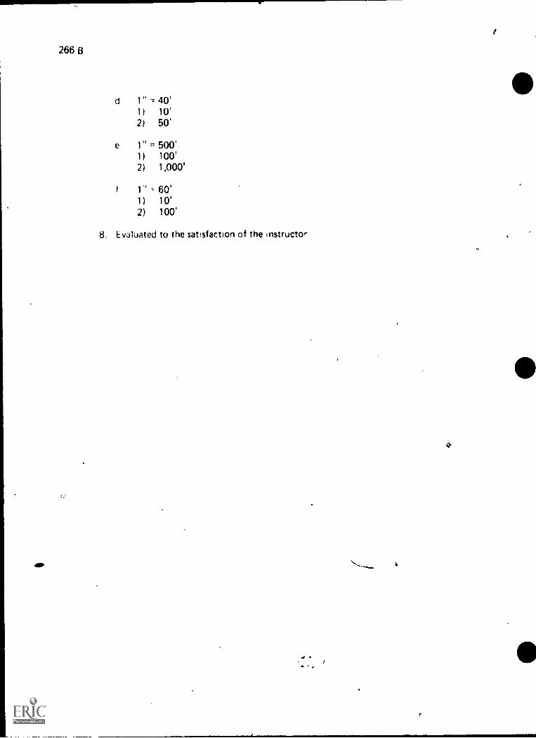
266 B
d1) 10'2) 50'
e 1" ,,, 500'1) 100'2) 1,000'
i 1" = 60'1) 10'2) 100'
8. Evaluated to the satisfaction of the Instructor
41P \ -.., i,
4 .
,
G.
I

"I
MECHANICAL ENGINEER'S SCALE USAGEUNIT VII
UNIT OBJECTIVE
D I - 267-8
,After completion of this unit, the student should be able to describe a mechanical engineer'sscale and state the purpose for using one. The student should also be able to list ratios foundon a mechanical engineer's scale and read the ratio scales correctly when measuring lines.This knowledge will be evidenced by correctly performing.the procedures outlined on theassignment sheets and by scoring 85 percent on the unit test.
SPECIFIC OBJECTIVES
After completion of this unit, the student should be able to:
1. Match terms related to mechanical engineer's scale usage with their correctdefinitions.
2. Describe a mechanical engineer's scale.
3. State the purpose for .using a mechanical engineer's scale.
4. Identify five basic shapes of scales.
5. Select rules for correct scale usage.
6. List four scale ratios that are found on a mechanical engineer's scale.
7. Interpret scale graduatiohs found on a mechanical engineer's scale.
8. Demonstrate the ability to:
a. Read the mechanical engineer's scale at the scale ratio of 1" = 1" (Full size)
b. Read the mechanical engineer's scale at the scale ratio of 1/2" = 1" (Half size)
a.
c. Read the mechanical engineer's scale at the scale ratio of 1/4" = 1" (Quartersize)
, d Read the mechanical engineer's scale at the scale ratio of 1/8" = 1" (One-eighth size)
e. Measure lines accurately with various scale ratios on a mechanical engineer'sscale
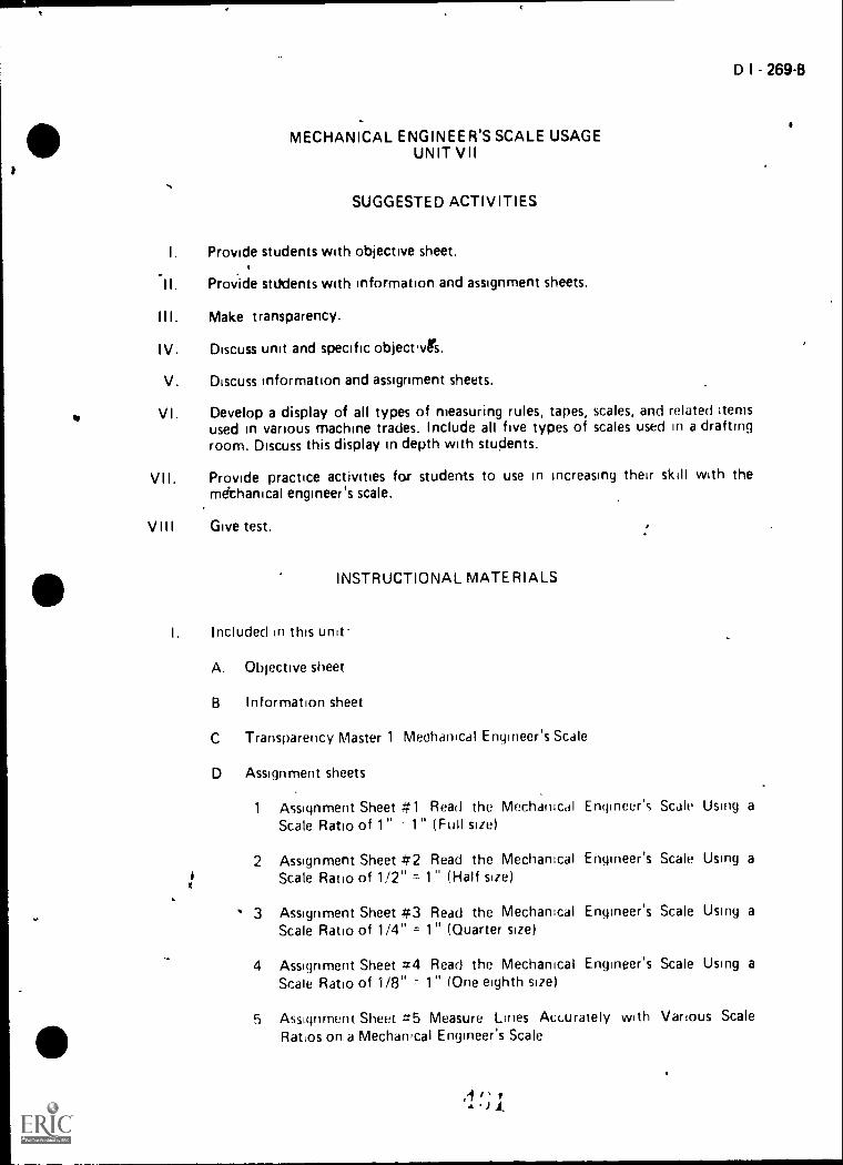
D I - 269-B
MECHANICAL ENGINEER'S SCALE USAGEUNIT VII
SUGGESTED ACTIVITIES
Provide students with objective sheet.
Provide stUdents with information and assignment sheets.
Make transparency.
Discuss unit and specific object.vrs.
Discuss information and assignment sheets.
Develop a display of all types of measuring rules, tapes, scales, and related itemsused in various machine trades. Include all five types of scales used in a draftingroom. Discuss this display in depth with students.
Provide practice activities for students to use in increasing their skill with themechanical engineer's scale.
Give test.
INSTRUCTIONAL MATERIALS
Included in this unit.
A. Objective sheet
B Information sheet
C Transparency Master 1 Mechanical Engineer's Scale
0 Assignment sheets
1 Assignment Sheet #1 Read the Mecharucal Engineer'sScale Ratio of 1" 1" (Full size)
2 Assignment Sheet #2 Read the Mechanical Engineer's
xiScale Ratio of 1/2" = 1" (Half size)
3 Assignment Sheet #3 Read the Mechanical Engineer'sScale Ratio of 1/4" = 1" (Quarter size)
4 Assignment Sheet #4 Read the Mechanical Engineer'sScale Ratio of 1/8" - 1" (One eighth size)
5 Assignment Sheet #5 Measure Lines Accurately withRatios on a Mechanical Engineer's Scale
/'
Scale Using a
Scale Using a
Scale Using a
Scale Using a
Various Scale

B
; ;runt irr
Aii,,Aeri, te.1
Walter C Drafting tor Inanstry. South HoILid IL 60473 TlwWillcox Company, Inc 19/4.
jonri n'ontas dmi Henry Cocd Snenr,:r Basic 7i,cho1( al D,aw figOtt' NY 10022 Macrnilldi, Puhlishing Co., 1968
, FrederiLk E., et dl reciwical Drawing. New York, NY 10022'Mdcmillan Publtshing Co., Inc., 1980.
0-1,0n, Cecil dnd Jay Helsel Engineering Drawing airi De.;ign New Yo,k,J (or'11 D,visirin;McGraw Hill Book Company, 1979
P D,Iffltry Terhr ,Ioay aml Practice Peoria, IL 61615A. Beiiett Cu 19/3

S.
MECHANICAL ENGINEER'S SCALE USAGEUNIT VII
INFORMATION SHEET
I. Terms and definitions
D I 271B
A. Actual size An object's actual dimensions, the size it actually is in completed form
B. Scale- An instrument used as a standard of reference when drawing anobject to a proportional size
C. Draw to scale -Drawing an object at some set proportion such as half itsactual size, one fourth its actual size, or double its actual size
D Open divided scale -A scale with only the end unit subdivided into fractionalparts
E Full divided scale A scale with the basic units subdivided throughoutthe length of the scale
F Graduations- The subdivisions in a scale unit, all of which are equal in size orlength
G Scale ratio A relationship between dimensional values used to reduceor enlarge the size of an object so that it can be drawn
H Fraction A part of a whole, such as 1/2 or 1 /4
I I Description of mechanical engineer's scale A scale commonly used by mechanicaldrafters because of its scale ratios; the mechanical engineer's scale is divided intounits representing full size (1" = 1"), half size (1/2" = 1"), quarter siie (1 /4" 1"),and one eighth size (1/8" = 1")
(NOTE The mechanical engineer's scale is sometimes called a mecharucaldrafter's scale
HI Purpose for using a mechanical engineer's scale To provide a standard of teference that is needed when drawing mechanical ports where the dimension,, <ire ininches or fractions
(NOTE It allows objects that are too large or too small to be drawn actual size tobe drawn to a usable proportion.)

277 B
INFORMATION SHEET
r0:11 ioJwI
<__
_
L 1 It! :WV,izr flr; 1
'
0,0 'I
D p() k Cott',1J_, f)r,j V -It2r ;)o.nts

D I 273-8
INFORMATION SHEET
E. Protect the edge of the scale to prevent damage to its graduation marks
F? Make a short dash rather than a point to mar* a distance
G. If a series of measurements are to be made on full size scale, do riot movescale for each measurement, but set off measurements with scale in .one
position
H. Make sure that the eyes' line of sight does not create an optical illusion and
thus an Incorrect measurement
Scale ratios found on a mechanical engineer's -sale
A. 1" 1"--Full size
B. 1/2" = 1"--Half size,
C. 1/4" = 1"- Quarter size
D. 1/8" 1"-One-eighth size
(NOTE. On some mechanical engineer's scales you will find a 3/8" = 1",and 3/4" = 1", but these are not considered standard reduction scales )
V I I. How io interpret scale graduations found on the mechanical. engineer's scale
A. 1" = 1" (Full size) Measurem nt is made by reading directly from fullsize scale in inches and fractrons
Example To measure tI distance indicated on the scale below, startat 0 and the point being measured (in this case it is 2"), next,determine the number of 1/16" units between the last fullinch and the point beind measured (in this case there are.thirteen 1/16" upits), add the inches and the fraction, aridthe measurement is 2 13/16"
113/16'
1
STANDARD 1/ T,
16/GRADUATIONS
1.1
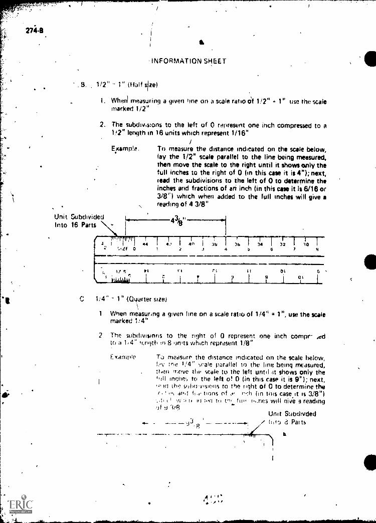
INFORMATION SHEET
B. 1/2" 1" (Half size)
1. Whed measuring a given line on a scale ratio Of 1/2" 1" use the scalemarked 1/2"
2. The subdivisions to the left of 0 represent one inch compressed to a1/2" length in 16 units which represent 1/16"
Example. To measure the distance indicated on the scale below,lay the 1/2" scale parallel to the line being measured,then move the scale to the right until it shows only thefull inches to the right of 0 (in this case it is 4"); next,read the subdivisions to the left of 0 to determine theinches and fractions of art inch (in this case it is 6/16 or3/13v) which when added to the full inches will give areading of 4 3/8"
Unit SubdividedInto 16 Parts
7_0
1/ 4" 1" 4C/toner size)
1 When measuring a given line on a scale ratio of 1/4" = 1", use the scalemarked 1:4"
2 The 'subdivisions to the right of 0 represent one inch comprto a 1,4" tcnijth in 8 units which represent 1/8"
Ex,imple To measure the distance indicated nn the scale below,Zne 1/4" scale tiarafiel to the line being measured,
:heti rr;ove the scale to the lett until .11 shows only theinche,, to the left of 0 (in this case it is 9"); next,
,01(1 the shhh-v4sions to the fight of 0 to determine ther. t tions of of ri:h (in Ibis case.it is 3/8")
kiv to 1(1 tool tt) tn, ftw nric3 will give 3 reading:)f 1'8
Unit Subdivded,/ 1:,te) 8 Paits
':14K/
1

,,.
INFORMATION SkEET
i1
D. 1/8" = 1" (one-eighth size)
1. When measuring a given lir,e oni, a scale ratio f 1/8" = 1", use the scalemarked 1/8 1
D 1 - 275-8
2. The subdivisions to the left of 0 represent oI7 inch compressed to a1/8" length in 4 uriits Which reviresent 1/4" ,
Example.: To measure thti distance indicat d on the scale below,lay the 1/8 scale parallel 10 the line being measured,then move the;scale to the right til it shows only thefull inches to the right of 0 (in thi case it is 18"); next,read the subdivisions to the left of 0 to determine theinches and fractions of an inch lin ihis case it is 3/4"),which when added to the full inche will give a readingof 18 3/4" 1
1
Unit Subdivided \
Into 4 Parts
, N1 iiri/8 0
183/4
.1,
I I
41
1
4418
4cI I 121
40
0
11 1u g
1- I I I 1
16 I 20 I
38 36

Mechanical Engineers Scale
1"=1" Full Scale '
16 I [TIT FIT1 trIMITT1 l TPTIITTP 91 MI PI/II
11111111111 Ilq
3-10$'121 7°2 II I i iii I i lrin till iToPl 17(gPl lif 1 ii3r? I
16 Subdivions in 1 st Unit
I
1
i ,
One-Eighth Size (1/8" =1")
oo 20
[II 9th
One-Half Size (1/2"=1")412 1 410 1 38 1 36 1 34 1- 312 I 310 I 28 1 2161
SIZE 0 8 92 3 4 5 6 7
0, 3ZIS ZZ , IZ OZ 61. 81. LL 91 91 Pt et C
I Lila 1 I 1 ti' 1 ? 1 II I csil I III 1 `PII I 911 1 EiL i (15
I8 Subdivions in 1 st. Unit
,i , . 4..0 ....
One-Quarter Size (1/4"=1")
An alternate form of mechanicalengineer's scale is shown at right
4 C 9

D I - 279-B
MECHANICAL. ENGINEER'S SCALE USAGEUNIT VII
0
- ASSIGNMENT SHEET #1--READ THE MECHAN4CAL ENGINEER'S SCALEUSING A SCALE RATIO OF 1" = 1"
Directions: Read the measurements shown below at 1" = 1" scale (full size). Read thelengths from 0 at left of points indicated on the scale. Place the correct measurements inthe blanks below the figure .
B.
41
C.
D.
E.
111111tillrui111111 lip-1111i iJT T-Tipi flpiriTH1111 1111
1

,
1
!
,.
DI- 281-B
,MECHANICAL ENGINEER'S SCALE USAGE
UNIT VII
ASSIGNMENT SHEET #2-READ THE MECHANICAL ENGINEER'S SCALEUSING A SCALE RATIO OF 1/2" = 1"
Directions: Read the messureMents shown below at 1/2" = 1" scale (half size). Read
the full inch units from 0 to the right and the fractional units to the left. Place the correct.,measurements in the blanks below the figure.
'
A.
B.
C.
D.
B.
C.
4
NOT TO SCALE
-
4;1,
-;
..,
Ii
..
.

0 1 283-8
MECHANICAL ENGINEER'S SCALE USAGEUNIT VII
ASSIGNMENT SHEET #3-READ THE VECHANICAL ENGINEER'S SCALEUSING A SCALE RATIO Ot '114" 1 " -
DirictiOns: Read the measurements shown below at 1/4" = 1" scale (quarter size). Read
the tull inch units from 0 to the left and the fractional units to the right of 0. Place thecorrect measurements in the blanks below the figura.
A.
114 11
1 1
22 16 16 1011
62
2 9170$125 4
111111P
9i
A.
B.
C.
D.
21 OZ CZ1 I i 1 LILLIALIALLIAI
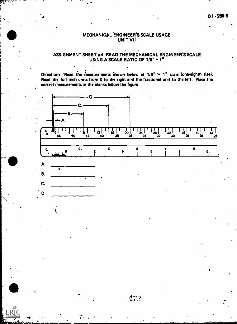
fa
0 1 285-8
MECHANICAL 'ENGINEER'S SCALE USAGEUNIT VII
ASSIGNMENT SHEET 414-READ THE MECHANICAL ENGINEER'S SCALEUSING A SCALE RATIO OF 1/8" 1 sr
Directions: 'Read ihe ineasurements Shown below at 1/8" 1. 1" scale (one-eighth size).Read the full inch units from 0 to the right and the fractional unit to the left. Place thecorrect measurements in the blanks Wow the figure.
A.
i 440
11121 11014 /41 ' 1 48 I ' 13'21 ' 3141 I 1'41 t4 I42 40 38 30 34 32 30 20 20 34
A.
8.
C.
D.
otLiLikuiko
At
DS.
01

D - 287-B
MECHANICAL ENGINEER'S SCALE USAGEUNIT VII
ASSIGNMENT.SHE ET *5-MEASURE LINES ACCURATELY WITHVARIOUS SCALE RATIOS ON A MECHANICAL Ett94EER'S SCALE
Directions: Measure tho lines A through F to the scale heading each column in .the table.Letter the scale readings in the appropriate space in the table.
Example: Measure Line A to the scale 1/2" = 1". A reading of is
obtained. This dimension is lettered under the 1/2" = 1" column and oppo-
site the letter A. Use guide lines for 1/82 lettering.
(NOTE: --Readings: must be accurate or they will be considered wrong.)
a
1/2" .= 1" 1/4" = 1" 1/8" ft1"
A .
B
C
_
-D .
,
.
E
F
1111111.1101111111
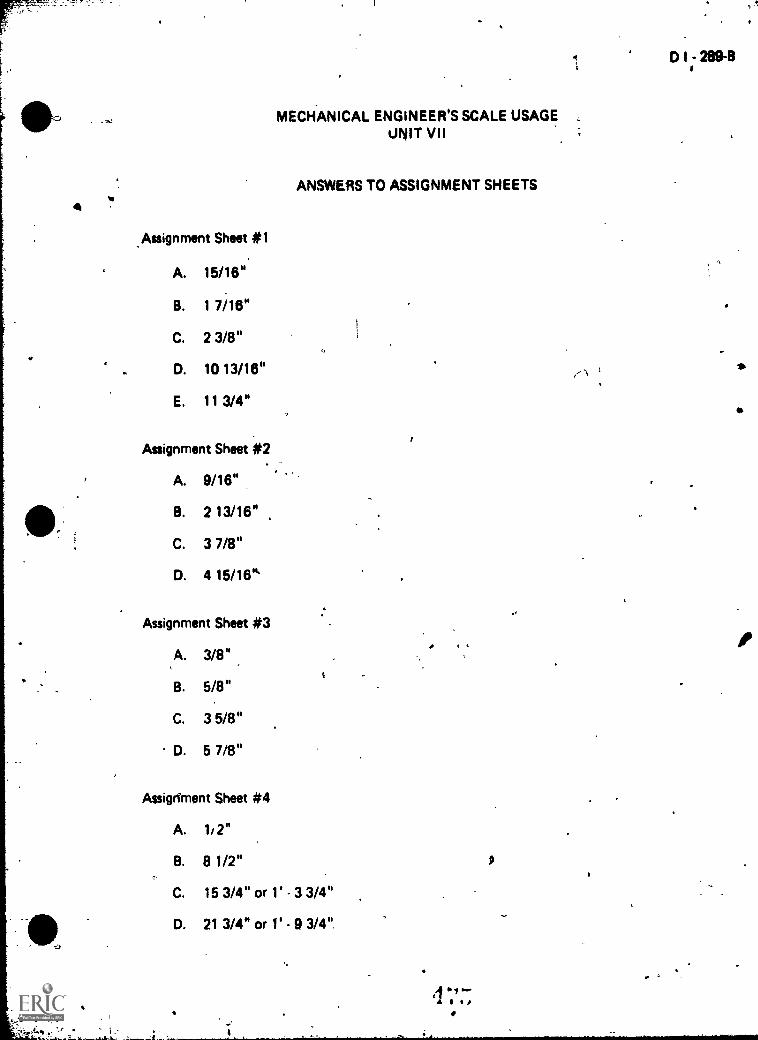
MECHANICAL ENGINEER'S SCALE USAGE ,
UNIT VII
ANSWERS TO ASSIGNMENT SHEETS
Assignment Sheet *1
A. 15/16"
B. 1 7/16"
C. 2 3/8"
D. 10 13/16"
E. 11 3/4"
Assignment Sheet *2
A. 9/16"
B. 2 13/16"
C. 3 7/8"
D. 4 15/16'
Assignment Sheet #3
A. 3/8"
B. 5/8"
C. 3 5/8"
D. 5 7/8"
Assigdment Sheet #4
A. 1/2"
B. 8 1/2"
C. 15 3/4" or 1' - 3 3/4"
D. 21 3/4" or - 9 3/4",
D I - 289-13

290,8
Assignment Sheet #5'
1" = 1"
A 4 15,32
3 106"
D 7 32"
F 2 15,16"
1:2" - 1" 1/4". 1" 113" .1"_3r.;
29 in"
rC 16/10 17 /,8"
3+8" 14 3;4
6 1/8" 12 1/4" 24 1/2"
8 7,/16" IS 7 11" 33 3/4"
2 1/2"
5 7/8" 11 '3/4" 23 1/2'
s.
i.

,
4
i
,
MECHANICAL ENGINEER'S SCALE USAGEUNIT VII
.--,''
NAME*
TEST.
D I - 291-8
11. Match the terms on the right with their correct definitions./
11. An object's actual dimensions, the size itactually is in completed form
b. An instrument used as a atandard of referen.qwhen drawing an object to a proportional siza
c. Drawing an object at some set proportionsuch as half its actual size, one fourth itsactual size, or double its actual size
d. A WSW with only the,end unit subdivided intofractional parts --
e. The subdivisions in a scale unit, all of whichare equal in size or length
f. A relationship between .dimensional valuesused to reduce or enlarge the size of an objectso that it can be &awn
A
9. A part of a whole, such as 1/2 or 1/4
h. A scale with the basic Units subdividedthroughout the length of the scale
/2. -Describe a mechanical engineer's scale.
_
I
qt 4
1. Graduations
2. Fraction
3. Open-divided scale
4. Scale4
5. Actual size
6. full-divided scale
-1-.---9cearratio
8. Draw to scale
*
. 14
I
*
..-
..,
*
4.
\L,
\
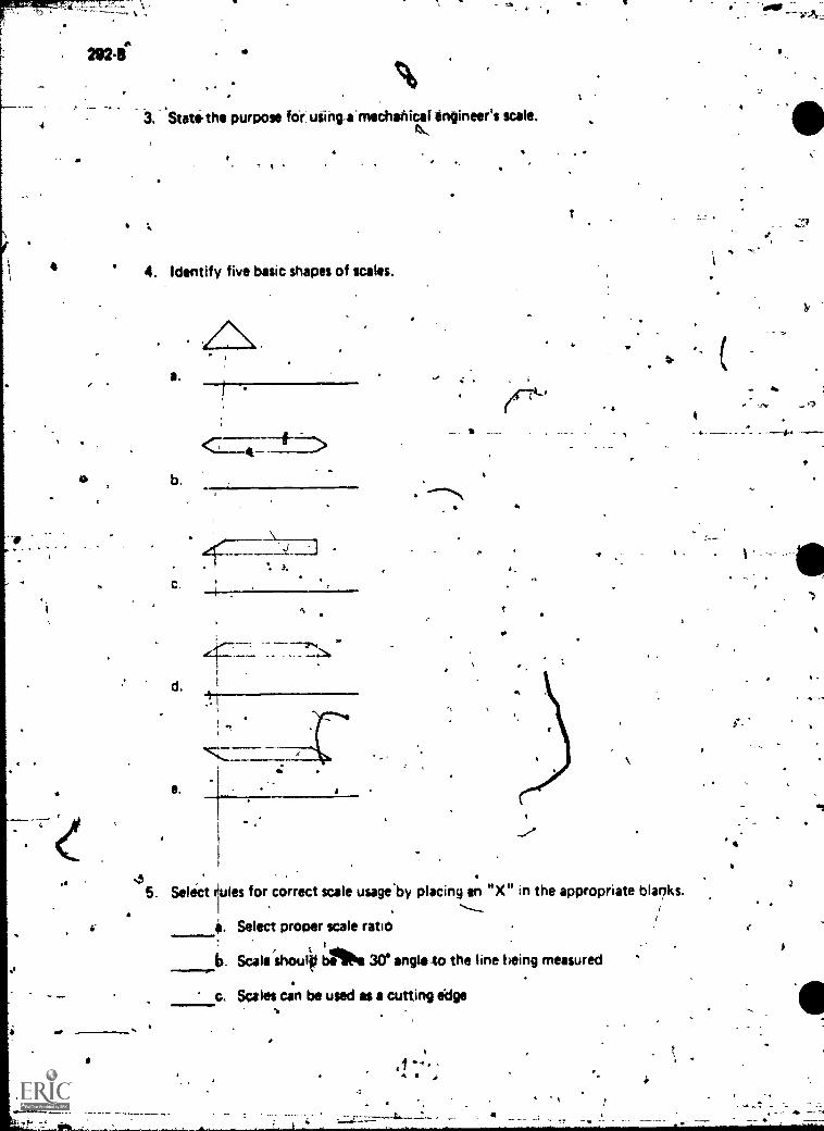
3. State.the purpose fo-r using_a-mechahicat engineer's scale.
4. Identify five basic shapes of scales.
cis
.
IS-
..,. .
5. Select lutes for correct scale usageSby placing an "X" in the appropriate blanks....._
. Select proper scale ratio. ,
b. Sca shoulfl AN Wangles() the line being measured ., 1..
..... le
c. Scales can be used as a cutting edge
.144 4
_
",
44. Alb

I /-- :I- -.)
P : i
es
:
d. Scale should lay:flit on the :4'1pm-being Measured
..- -e` Make a short dash rather Vain a point to mark a distance
f. Stick compass or divider points into scale to set instruments
Protect the edge
h. lf a seriee ofscale for oathpoon-
of the- scale to prevent dam* tAilis graduation mirks
gaments anflo be Made on the full siie scale, do not mbviuurement, but set off measurements with scale in one
i. Make sur: that the eyes' lint of sight does not create an optical illusionthus an incorrect measurement
44 List four scale ratioi that are found on a mechanical engineer's scale.
d.
7. lnterpretgraduations on-the erigineer's scale.I.
2)
3)
.'-
4 -I,i .!
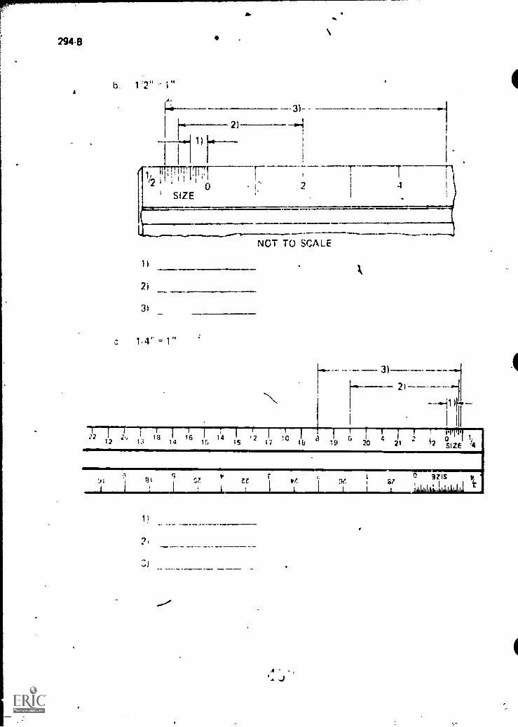
294-8
b 1 '2" 1"
12
--1-102 0 4
SIZE2
1,4" = 1"
NOT TO SCALE
16 14 1214 IS 11 Us 19 21 2 °SIZE
0 32ISSF0? Zt tf,

D I - 295-B
d. 1/8" = 1"
1)
r78 11 101 1111111111/ 112 I 116 011 I )4 I 1- I ' 312 316 1 "J. I 1 a4 1446 4 4 4 2 4 0 3 8 36 34 3 2 30 28 26 2
0Lau 821--I-- PI
91
1)
2)
8. Demonstrate the ability to:
9
a. Read the mechanical engineer's scale at the scale ratio of 1" = 1" (Full size)
1. Read the mechanical engineer's scale at the scale ratio of 1/2" = 1" (Half size)
c. Read the mechanical engineer's scale at the scale ratio of 1/4" = 1" (Quartersize)
d. Read the mechanical engineer's scale at the scale ratio of 1/8" = 1" (One eighthsize)
e. Measure linet accurately with various scale ratios on a mechanical engineer's scale
(NOTE: If these activities have not been accomplished prior to the test, ask yourinstructor when they should be completed.)

I - 297-8
1.
MECHANICAL ENGINEER'S SCALE USAGEUNIT VII
ANSWERS TO TEST
a. 5 e. 1
b. 4 f. 7
c. g. 2d. 3 h. 6
2. Description should include:
A scale cc lmonly used by mechanical drafters because of its scale ratios; the mech-anical engineer's scale is divided into units representing full size (1" = 1"), half size(1/2" = 1"), quarter size11/4" 1"), and one-eighth size (1/8" 1")
3. To provide a standard of reference that is needed when drawing mechanical partswhere the dimensions are in inches or fractibns
4. a. Triangularb. Four-bevelc. One-beveld. Two-bevele. Opposite-bevel
5. a, d, e, g, h, i
6. a. 1" = 1"b. 1/2" zi 1"C. 1/4"'= 1"d. 1/8" = 1"
7: a. 1) 1 5/16"2) 2 3/8"3) 3 1/16"
b. 1) 3/8"2) 2 5/8"3) 5 7/8'
C. 1) 5/8"2) 6 3/4"3) 8 7/8"
d. 1) 11 1/4"2) 19i 1/2"
8. Evaluated to satisfaction of the instructor

METRIC SCALE USAGEUNIT VIII
UNIT OBJECTIVE
_
D I - 299-13
After completion of this unit, the student should be able to describe the purpose for using a* , metric scale and be able to list standard scale ratios to which objects can be drawn with the
'metric scale. The student should be able to interpret scale graduations and correctly measurelengths with the metric scale. This knowledge will be evidenced by correctly performing the
procedures outlined on the assignment sheets and by scoring 85 percent on the unit test.
SPECIFIC OBJECTIVES
After completion of this unit, the student should be able to:
1. Match terms related to metric scale usage with their correct definitions.
2. State the purpose for using a metric scale.
3. Identify basic shapes of inetric scales.
4. Select rules for correct scale usage.
5. Explain a scale ratio.
.c.
6. Distinguish between a reduction scale ratio and an enlargement scale ratio.
17. Select metric scale ratios commonly used for various drafting applications.
8. List commonly used scale ratios found on triangular metric scales.
9. Interpret scale graduations on a full divided 1:1, 1:100 metric scale.
10. Interpret metric scale ratios commonly used for machine drawings.
11. Interpret metric scale ratios commonly us id for architectural construction details,
12. Demonstrate the ability to:
a. Read the metric scale at the scale ratio of 1:1.
b. Read the metriegAde at the scale ratio of 1:2.s.
c. Read the metric scale at the scale ratio of 1:5.
41( ' )a t..4 . 4

d. Read the metric scale at the scale ratio 1:25.
e. Read the metric scale at the scale ratio 1:33 1/3.
1. Read the .etric scale at the scale ratio 1:75.
g. Measure lines accurately with various scale ratios found on a metric scale.
AN*

's
I
, D I - 301B
METRIC SCALE USAGE cUNIT VIII
SUCGESTED ACTIVITIESt
i
I. Provide students with objective sheet. -
II. Provide students with information and assignment sheets.
III. Make transparenciet4,
IV. Discuss unieand specific objective&
V. Discuss information and assignment sheets.
VI. Develop a display of all types of measuring rules, tapes, scales aid related itemsused in various machine and building trades. Include all five types of scales used ina drafting.room. Discuss this display in depth with students.
VII. Have students practice measuring objects in the classroom.
VIII. Use metric comparison charts in discussing the use of metric scales.
411kaIX. Give test.
INSTRUCTIONAL MATERIALS
I. Included in this unit:
A. Objective sheet
B. Information sheet
C. Transparency m4sters
c 1. TM 1.-Metric Scales (Triangular) I
2. TM 2--Frequentiv (Vsed Metric Reduction Scales
3. TM 3--Frequently Used Metric Enlargement Scales
D. Assignment sheets ,
1. Assignment Sheet #1--Read the Metric Scale at the Scale Ratio of, 1:1
2. Assignment Sheet #2.-Read the Metric Scale at the Scale Ratio of1:2
3. Assignment Sheet #3--Read the Metric Scale at the Scaie Ratio 1;5
t

302 B
Asserrnent Sheet #4- Read the Metric Seale at Vie Sra le Ratio 1:25
Assiortruunt S!reet 45 -Read me Metric Scale at th Scale Rat 4o 1.331'3
Assionment Sheet #6 -Read the Metric Scale at the Scale Ratio 1.15
Ass03.1.,ient .heet #7..Measure Lines Accurately with Various ScaleRatios Found on a M tric Scale
t,r,vors to assipment steets
Test
Answcis to test
11 References:
Brown, W.Ilter C! Drafting for Piclustry. South Holland, IL 60473. Theiiipart Willcox Company, Inc 1974.
1),, :001 Joh Troi.las and Henry Cecil Spencer. Basic Technical Dr.itving,Nf-N Yo,k, N) 10022. Macmillan Publishing Co Inc 1968
Freqe, E . et ,rI To-hrucal Drawing. Naw York, NY 10022-: drmilIan Puoilishing Co Inc, 1980.
Jonsei, Cccil and Jay HP'sel. Engineering Drawing and Design, N.,AN York,NY Division/McGraw Hit! Book Company, 1919.
Willhan P. Drafting Technology and Pract.ce Peoria, '1. 61615Chas A Ber lett , Inc , '19/3
'opence P and Au-sini, Micha,,, 6., lechnical Diafting Alefr, Designpv: Cf:norlarliCdt1011 Pere hi IL b1615. Chas. A Bennett Co., Irc 1980
6
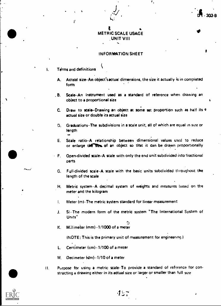
%
f'
d .METRIC SCALE USAGE
.UNIT VIII .*v.
INFORMATION SHEET
. kI. Terms and definitions
#
A. Actdal size--An objecesactual dimensions, the size it actually is in completedform
B. Scale-An instrument used as a standard of reference when drawing anobject to a proportional size i
C. Draw to scale-Drawing an object at some set proportion such as half its Gactual size or double its actual size
D. Graduations-The subdivisions in a scale unit, all of which are equal in size orlengthaltal
E. Scale ratioA relationship between dimensional values used to reduceor enlarge thirs'Ift of an object so trtat it can be drawn proportionally
....._..1
F. Open-divided scale-A scale with only the end unit subdivided into iractionalparts
G. Full-divided scale-A scale with the basic units subdivided throughout thelength of the scale
H. Metric system--A decimal system of weights and measures based on thee meter and the kilogram
I. Meter (m)-The metric system standard for linear measurement
J. SI--The modern form of the metric system "The International System ofUnits"
5K. Mlimeier (mm)--1 /1000 of a meter
(NOTE: This is the primary unit of measurement for engineering )
L. Centimeter (cm)--1/100 of a meter
M. Decimeter (drn)-1/10 of a meter
II. Purpose for using a metric scale-To provide a standard of reference for con-. structing a drawing either in its actual size or larger or smaller than full size
.1 c- ~.a ../ 4

304 a
INFORMAT ION SHEET
Basic shapes ot metric scares
A Oval
B. Two bevo
C. Opposite Bevel
D. Four bevel
E. Trtangular
IV. Rules fcr correct scale usage
A. Sek it proper 3cale ratio
B. Sr.ale shohld lay fiat on the surface hei,g treasurtid
C should be parallel with or on line being measured
O. Do not st,:k cempass or divider nolgrs into scale
E Protuct I w edge ot the scale to prevent darnarie to its graduat,on marks
F Mike a short dash rather loan a noint to mark d distance
G tf c of measurements arc RI be made on full sr.re scale, do not trovescale for each cleasurenient, but set off measurements with scale in oneposition
H. Maxe sure that the eyes' hne of sight dces not create an optical IUSIOfl andthus are incorrect measurement
v't
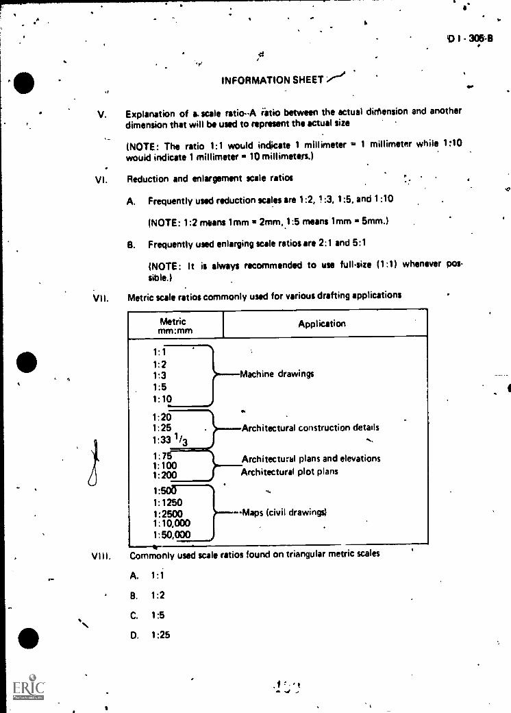
...
t
0 I - 305-6.71
INFORMATION SHEET ,-""00
V. Explanation of &scale ratio-A retio between the actual dimension and anotherdimension that will be used to represent the actual size
(NOTE: The ratio 1:1 would indicate 1 millimeter = 1 millimeter while 110would indicate 1 millimeter 10 millimeters.)
VI. Reduction and enlargement scale ratios ..- .
A. Frequently used reduction scales are 1:2, 1:3, 1:5, and 1:10
(NOTE: 1:2 means 1mm = 2mm,.1:5 means 1mm = 5mm.)
B. Frequently used enlarging scale ratios are 2:1 and 5:1
(NOTE: It is always recommended to toe full-size (1:1) whenever pos-sible.)
VII. Metric scale ratios commonly used for various drafting applications
J
Metricnln,:nnir -
Application
1:1
1:21:31:51:10
1:201:251:33 1/3
1:751:1001:200
1:
1:12501:25001:10,0001:50,000
)--Machine drawings
..
.1wwww
Architectural construction details
Architectur& plans and elevationsArchitectural plot plans
4.
--Maps (civil drawings)
.. VIII. Commonly used scale ratios found on triangular metric scales
.- A. 1:1
\B. 1:2
C. 1:5
D. 1:25
.1 f,'t- -0 ,

306 B
INrORMATIONSHEET
E. 1. 33 1 '71
1 751'
IX. How to interpret scat,: i_inirluations forbid -on a full-divided 1.1, 1 '1 00 metrica I
A. Many metric scales have multiple scale rdtios dlon9 one edge to allow for avariety of scales to be used from a single ingrument
B. The 1:1 (full size) scale ratio is the basic scale ratio used; each subdivision isactuatly 1 rfan in width with the calibrations numbered at 10 mm intervals
E '<ample On the 1.1 scale ratio, line X in the figlire beloWis 100 mm:ono, but on the 1.100 scale ratio at the bottom of the scale,ITie X would be 10,000 mm or 10 meters long
.0'7'T"711-.111'F.T1T111111 Fril I 4711" ! I101, Ac r '1 41(1
,
1,,
- e
X comilionly ut.t.d for machine dravnngs
A i I rano (full nds scale yilmlivision 1 mm in width wim calibrationsriirotrerqo in 10 min mr,roleirts
No r F. Sryne have subdivisions in 1.'2 inm, and these should notbe r Jrifrit1 e.Tth I ,,binddrd 1 min subdivisitios.)
.nade t rear:m.1 rirriTtly from the 1:1 scale ratio iniF .iptri.
Orvn2 3O 4O 6O ro;oo
11.--,0L-Ti 5 6-1-- 7_ _
x1 i00 ITTM AT 1.1x=1,000 mrn AT 1.10x.10,000 mrn. AT 1 100
'Jr-E 1
1 1

,
I
..1
0 I 307-13
INFORMATION SHEET
..Ap 2. When read f :10, .this scale ratio is used for machine drawings, when 0read 1:100, this scale.ratio is used fpr architectural drawings, and when
: read 1:1000, this scale ratio is used for map drawings t. B. 1:2 'ratio (half size) has scale subdivisions representing 2 mm of width with
calibrations numbered in 20 mm increments`ay
1. Measurements are. made by reading directly from the 1:2 scale ratio inmillimeters (Figure 1)
2.. When read 1,10, this scale ratio is used for machine drawings, 'whenread 1:200, this scalp ratio is used for architectural drawings, an'd when
t'''' reac1:2000, thisscale ratio is used for map drawing
C. 1:5 ratio (Qre-fifth size) has scale subdivisions representing 5 mm of widthwith calibrations numbered in 100 mm increments
*1. Measurements are made by reading directly fr8m the 1:5 scale ratioln
millimeters (F igure 2),
X l.
FIGURE 2
2. When read 1:50, this scale ratio is used for machine drawings, whenread 1:500, this scale rein is used for architectural drawings, and whenread I.:50p0, this scale is used for map drawings
.--. ..
Metrie scale ratios commonly used for architectural construction details.-
A. 1:25 ratio has subdivisions' representing zo mm of, width with calibre-. tions numbered in .500 'mm increments, and measurements are made by
reading directly from the 1:25 scale ,in meters and millimeters (Figure3) .
r .* B. .11y1f3 . ratio has subdivisions representing 20 mm of width with cali-
brationt numberea in 1000 mm increments, and measurements are made by" reading directly from the 1:33 1/3 scale in millimeters ,( F igure 3)
-.... .
11
,.-
..is. .,
'. . ' .
.-
t
%.
1

INFORMATION SHEU
20 ram
FIGURE 3
C. 1:75 ratio ras subdivisions representing 50 mm of width with calibra .tions numbered in 1000 mm (1 rn) increments, ow) measuroments are madeby reading direct! from the 1:75 scale in millimeters (Figure 4)
1560mm 4-4,II5Omml
1:331/3 RATIO METRIC SCALE
10
1:75 RATIO METRIC SCALE-2350mm
L._ - -4470mm
f-i(JURE 4
,11,0k wo
0 cz
50 mm

Mei& Scales(Triangular)
1 1 :1 RATIO METRIC SCALE (Full-Size
1 - 3(10-4
5mm
1:2 RATIO METRIC SCALE (Half -Size)
t4
29Orrim175mm
I 5 100mm 200 3 0
op ot oz o III ir:1111:01u ntlitinkilI
-1 2 mm35mm
is-49mm
RATIO METRIC-SCALE (One-Fifth Size)
1300 1400 1500mm
oc
1:25 RATiO METRIC SCALE-44 500mm
1000mm(I meter)
1:331/3 RATIO METRIC SCALE
20 mm.0%
1:75 RATIO METRIC SCALE
493TM 1

D I - 31141
Frequently Used Metric Reduction Scales
OBJECT (1:1)
I
1 2
1:3
-
TM 2

Frequently Used MetricEnlargement Scales
OBJECT (1:1)
c
D 1 - 313-1)
A
TM 3

D I - 3151I\
--IvMETRIC SCALE USAGE
UNIT yiii
ASSIGNMENT SHEET #1READ THE METRIC SCALEAT THE SCALE RATIO OF 1:1
Directions: Road the measurements shown below at 1:1 IOW ratio (full size). Read thelengths from 0 at the left side to the point indicated on the scale. Place the correct measure-ments in the blanks below the' figure.
a.
b.
C.
cl.
e.
1:10 10mm I 30 40 SO 60 . 70
i,
.
el I a fl4.11,/1/
,

ft
METRIC SCALE USAGEUNIT VIII
ASSIGNMENT SHEET #2--READ THE METRIC SCALEAT THE SCALE RATIO OF 1:2
D I - 317-6
Directions: Road measurements shown below at 1:2 'scale ratio (half size). Read thelengths from 0 at loft side to the point indicated on the scale. Place the correct measure-ments in the blsnkj below the figure.
a.
b.
c.
d.
e.
-c
460 4 500 5 0 560 WO 6
wOOE 06Z OK oa o OL 09 OS OE OZIPLuOt 01:1

4METRIC SCALE USAGE
UNIT VIII
ASSIGNMENT SHEET #1-READ THE METRIC SCALEAT THE SCALE RATIO OF 1:5
0114
,
D I - 319-11
N.Directions: Road the measurements shown below at 1:5 ratio. Read the lengths from 0 NNNat the left side to the point indicated on the scale. Place the correct measurements in theblanks below the figure. .
a.
b.
C.
d.
e.

DI-321-5
METRIC SCALE MAGEUNIT VIII
r""
ASSIGNMENT F, dEET #4READ THE METRIC SCALEAT THE SCALE RATIO OF 1:25
Directions: Read the measurements shown below at 1:25 ratio. Reed the lengths from 0at the left to the point indicated on the scale. Place the correct meesurements in the blanksbelow the figure.
r,
e.
r
&
b.
C.
d.
S.
.,

METRIC SCALE USAGEUNIT VIII
-ASSIGNMENT SHEET 405-READ THE METRIC SCALEAT THE SCALE RATIO OF 1:33 1/3
...
0 1 - 32311
Directions: Reed the measurements shown below at 1:33 1 /3 ratio. Read the iengths from 0at the left end to the point indicated on the scale. Piece the correct measurements in theblanks below the figure. .
a
e.

.
METRIC SCALE USAGEUNIT VIII
ASSIGNMENT SHEET #6-READ THE METRIC SCALEAT THE RATIO OF 1:75
^
D 1 325-5
f .
Directions: Read the measurements shown below at 1:75 ratio. Read the lengths from 0at the left end to the point indicated on the scale. Place the correct measurements in theblanks below the figure.
L
I
b.
C.
d.
I.
o
.
,
,
f
.
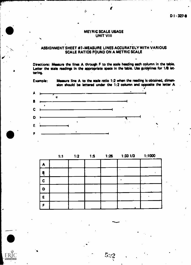
ID I - 3274
a
...
METRIC SCALE USAGEUNIT VIII
ASSIGNMENT SHEET #7-MEASURE LINES ACCURATELY WITH VARIOUSSCALE RATIOS FOUND ON A METRIC SCALE
DWections: Measure the lines A through F to the scale heeding each column in the table.Low the mak readings in the appropriate war in the table. Use guidtlines for US let-tering.
Example: Measure line A to the scale ratio 1:2 when the reeding is obtained, dimen-sion should be lettered under the 1:2 column and opposite the letter A.
A
e
c i
D
F
F
1:1 1:2 1:5 1:25
It
1:33 1/3 1:1000
A
w
W
g
C
- -
+.
ammeII
Al
0
E
MP
F- I
a
t":, -)1144 -

Assignment Shoat #1
a. 34 mm
b. 52 mm
c. mm
'd. 270 nim
t. 294 mm
Assignment Sheet *2
a. 30 mm
b. 56,mm
c. 480 mm
d. 518 mm
a. 550 mm
Assignment Sheet #3
a. 80 mm
b. 180 mm
C. 280 rnm -
d. 1300 mm
e. 1365 mm
Assignment Sheet *4
a. 660 mm
b. 1 m\.)
c. 6 m
METRIC SCALE USAGEUNIT VIII
ANSWERS TO ASSIGNMENT SHEETS
d. 6 m - 400 mm or 6400 mm
e. 6 m :920 mm or ONO mm MO*
.f)fr a 14
.
A
I - 329-8

Als;gnment Sneet 411
a. 600
I. 1000 :n") or 1 m
C. ,s1 rr. milli 04 1500 mori
d. 3m .300 nu or 8300 nlm
e. 9 ro 500 rim mm
Msignment Shtmt #6
a. 1 m 100 nun-c,r 1/00 mm
b. 3 m 150 rrn, or 3150 mm
c. 4nOOmmor4O0mm
d. 19 n. nr 19,000 mrn
e. 20 m 300 I r.n :t 2n,:30C
Assignment Shmt tt 7
1:2
113 nim 2 )7 mm
93 mm 1b(5 :rr
_107
30 n,y1 ,
I 73t
154 mn,
24L1 mm 536 rrr I 268 men 3:ie - m '1 n,r.}0 t 71 rr1.....
rr n. 160 mrn" iik- :Irv. ; 1 ( r rlro I ,1,00r,i-,-.....i, ------ ---- --4. - --- _ .... f _ _ . _
,lir , 364 ttlf-1, 192 mm I 244 r1m i,3ri rnni i.1
1:5 1 25 ; '3 1:1000
566 jam/42 i2.5 mmi 3/8 mm 11.3on mr2]
I =
466 rnml 233 inn" 310 PIT c! 300 trim
3E:6 mrni 193 mm I 267 Iv+Ir I ,7u mm

VS
0 METRIC SCALE USAGEUNIT VIII
NAME
TEST
1. Match the terms on the right with the c'orrect
a.
b.
egia'
D I - 331-8
An object's actual dimensions,, the sizeit actually 4 in completed form
An instrument used as a standard of reference!tchen driiving an object to a proportional size
-.
Drawing an Object At some, set proportionsuch as half its actual size or double ks actualsize .
d. The subdivisions in a scale unit, all of whiChare equal in size or length
e. A rilationship between dimensional valuesused to reduce or enlarge thesis, of an objectso that it can be drawn proportionally
f. A scale itith only the And unit subdividedinto fractional parts
g. 'scale with the basic units, subdividedthroughout the length of the scale
h. A dicimal system of weights and measu2,based on the meter and the kilogram
i. The metric :yr,- ; dard for lineer mu:surement
1. Meter
2. Open-dividedscale
3. Graduations
4. Actualiize
5. Draw toscale
8. Decimeter (DM)
7. SI
8. Full-disvkledscale.
9: Scale ratio
10. Millimeter (mm)
11. Scale
Metric systeM
13. Centimeter (Cm)
j. The modern form of the metric systenituThe International System of Units*
k. 1/1000 of a meter
I. 1/100 of a Teter
m. 1/10 of a meter
2. State thu purpose for usihg a metric scale.
44
e".. to ,)

3. Identify basic shapes of metric scales. ,
a.
b.
d.
mew. NEN.= .....m/le.0
e.
4. Select rules for correct scale user by placing an '')(u in the approriate blanks.
a. Select proper scale ratio
b. Scale should be at a cr angle to the line being measured
c. Scales can be used as a cutting edge
d. Scale should lay flat on the surface being measured
e. Make a short dash rather than point to mark a distance
f. Stick compass or divider pointi into scale to set instruments
g. Protect the edge of the scale to prevent damage to its graduation marks
h. If a series ot measurements are to be made on the full size scale, do not movescale for each measurement, but set off measurtments with scale in oneposition
i. Make sure that the eyes '. line of sight creates an opticalAsion arid thus anincorrect measurement

D I - 33341
5. Explain a scale reduction ratio.
6. Distinguish between a reduction scale ratio and an enlargement scale ratio by placingan "X" by each example of a roduction Kik ratio.
a. 1:2
b. 5:1
C. 1:5
d. 2:1
e. 1:33 1/3
f. 1:25
7. Select metric scale ratios commonly used for various drafting applications by placingan "MD" by those ratios commonly used for machine drawings, an "AD" by thoseratios commonly used for architectural plans, details and plot plans, and an uM" byAhose ratios commonly used for maps.
a. 1:1 i. 1:25
b. 1:50,000 1:100
c. 1:3 k. 1:200
d. 1:500 -A../ I. 1:5
e. 1:10 m. 1:20
f. 1:2,500 n. 1:10,000
g. 1:75 0. 1:2
h. 1:33 1/3
r.,:t 40,/., g

334-B
8. List commonly used scale ratios found On metric scales.
a.
b.
C.
d.
e.
f.
*NMI.
9. Interpret scale graduations found on a full divided 1:1, 1:10 metric scale.
1 l)!UHT/ 111.1M 1111'7 T'",r17/177/111 irliP"T1117: "Ti 1"
tl It 1 I 4 t;,At 1:1 ratio
a.
b.
c.
At 1:100 ratia
a.
C.
10. Interr.ret metric scale ratios commonly used for machine drawings
a Hb.
711 5 6 100, nrn
OCI I
At 1:5
a
C.
200
0(.3
+
- 300
011. I" tee 1110
46.

b.
c.
a
D I - 3315-13
10m 30 40 50 60 70
9 OBS ON 0 9 009 0 09t,
C. C.
11. Interpret scale ratios commonly used for architectural construction details.
C.
e
.01
b.
c.
b.
C.

336
At 1:25
a.
b.
C.
1.1,.....NIM
12. Demonstrate the abitity to:
a. Read the metric scale at the scale ratio of 1:1.
b. Read the metric scale at the scale ratio of 1 :2.
c. Read the metric scale at the scale ratio of 1:5.
d. Read the metric scale at the scale ratio of 1:25.
e. Read the metric wale at the scale ratio of 1:33 1/3.
f. Read the metric scale at the scale ratio of 1:75.
q. Measure lines accurately with various scale ratios found on a metric scale.
(NOTE: If these activities have not been accomplished prior to the test, ask yourinstructor when they should be completed.)
r.1
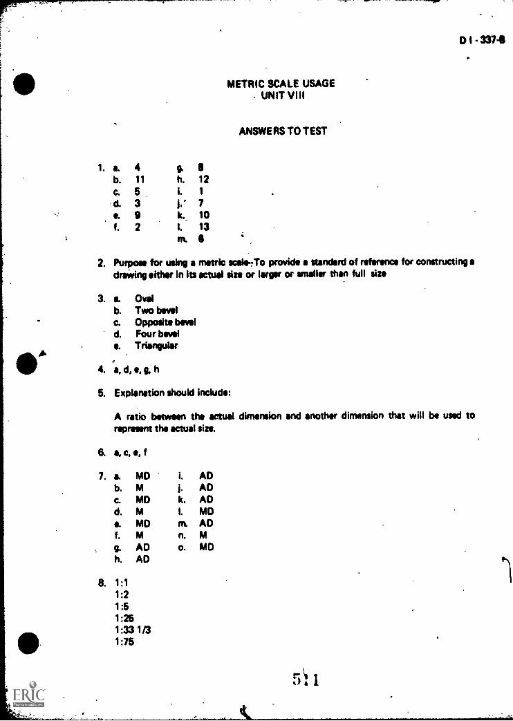
1.
METRIC SCALE USAGEUNIT VIII
ANSWERS TO TEST
a. 4 6 8b. 11 h. 12
C. 5 I. 1
d. 3 7S. 9 k.. 10f. 2 I. 13
on. 6
D I - 337-8
2. Purpose for using a metric scale-rTo provide a standard of reference for constructing adraWing either in its actual size or larger or smaller than full size
3. a. Ovalb. Two bevelc. Opposite beveld. Four bevelS. Triangular
4. a, d, e, g, h
5. Explanation should include:
A ratio between the actual dimension and another dimension that will be used torepresent the actual size.
6. a, c, e. f
7. a. MD I. ADb. M j. ADC. MD k. ADd. M I. MDe. MD m. ADf. M n. M
g.
h.ADAD
o. MD
8. 1:11:21:51:251:33 1/31:75
r 1A

oe
338.8
9.
1:1 Ratio
10.
11.
a. 14 mmb. 27 mmC. 40 mm
At 1:5 Ratio
a. 5 mmb. 175 mmc. 290 mm
At 1:1 Ratio
1:100 Ratio
a, 1.4 mb. 2.7 mC. 4.0 m
At 1:2 Ratio
a. 1 mm a. 2 mmb. 35 mm b. 35 mmc. 48.5 mm C. 49 mm
1:25 Ratio At 1:33 1/3 Ratio
a. 20 mmb. 500 mmc. 1000 mm
a. 20 mmb. 1150. mmC. 1560 mm
At 1:75 Ratio
a. 350 mmb. 1400 mmc. 2600 mm
12. Evaluated to the satisfaction of the instructor
1 2
11