Embed Size (px)
Citation preview

Filling levelsensorOriginal operating manual Series with
Modbus® RTU interfaceHFB MD Flex
Version BA-2016.11.28 ENPrint-No. 300 619
TR MA DE Rev002
ASV Stübbe GmbH & Co. KGHollwieser Strasse 532602 VlothoGermanyPhone: +49 (0)5733-799-0Fax: +49 (0)5733-799-5000Email: [email protected]: www.asv-stuebbe.com
We reserve the right to make technical changes.
Read carefully before use.
Save for future use.
Table of contents
Table of contents
1 About this document . . . . . . . . . . . . . . . . . . . . . . . . . . . . . . . 4
1.1 Target groups . . . . . . . . . . . . . . . . . . . . . . . . . . . . . . . . . 4
1.2 Other applicable documents . . . . . . . . . . . . . . . . 4
1.3 Warnings and symbols . . . . . . . . . . . . . . . . . . . . . . . 4
2 General safety instructions . . . . . . . . . . . . . . . . . . . . . . . 5
2.1 Intended use . . . . . . . . . . . . . . . . . . . . . . . . . . . . . . . . . . 5
2.2 General safety instructions . . . . . . . . . . . . . . . . . . 52.2.1 Obligations of the operating company . . . . . . 52.2.2 Obligations of personnel . . . . . . . . . . . . . . . . . . . . . 5
2.3 Specific hazards . . . . . . . . . . . . . . . . . . . . . . . . . . . . . . 52.3.1 Hazardous media . . . . . . . . . . . . . . . . . . . . . . . . . . . . 5
3 Layout and Function . . . . . . . . . . . . . . . . . . . . . . . . . . . . . . . 6
3.1 Type plate . . . . . . . . . . . . . . . . . . . . . . . . . . . . . . . . . . . . . 6
3.2 Description . . . . . . . . . . . . . . . . . . . . . . . . . . . . . . . . . . . . 6
3.3 Layout . . . . . . . . . . . . . . . . . . . . . . . . . . . . . . . . . . . . . . . . . 73.3.1 Housing and sensor . . . . . . . . . . . . . . . . . . . . . . . . . . 73.3.2 UNI display . . . . . . . . . . . . . . . . . . . . . . . . . . . . . . . . . . . 73.3.3 Measured value display . . . . . . . . . . . . . . . . . . . . . 7
4 Transport, Storage and Disposal . . . . . . . . . . . . . . . . . 8
4.1 Unpacking and inspection on delivery . . . . . . 8
4.2 Transportation . . . . . . . . . . . . . . . . . . . . . . . . . . . . . . . . 8
4.3 Storage . . . . . . . . . . . . . . . . . . . . . . . . . . . . . . . . . . . . . . . 8
4.4 Disposal . . . . . . . . . . . . . . . . . . . . . . . . . . . . . . . . . . . . . . . 8
5 Installation and connection . . . . . . . . . . . . . . . . . . . . . . . 9
5.1 Check operating conditions . . . . . . . . . . . . . . . . . 9
5.2 Install device . . . . . . . . . . . . . . . . . . . . . . . . . . . . . . . . . . 9
5.3 Electrical connection of device . . . . . . . . . . . . . . 9
6 Operation . . . . . . . . . . . . . . . . . . . . . . . . . . . . . . . . . . . . . . . . . . . . 10
6.1 Basic operation using the UNI display . . . . . . 106.1.1 Measured value display . . . . . . . . . . . . . . . . . . . . . 106.1.2 Parameterizing . . . . . . . . . . . . . . . . . . . . . . . . . . . . . . . 10
6.2 Initial start-up with UNI display . . . . . . . . . . . . . . 11
6.3 Managing several devices . . . . . . . . . . . . . . . . . . . 116.3.1 Backing up parameter sets . . . . . . . . . . . . . . . . . . 116.3.2 Parameterizing several devices . . . . . . . . . . . . . 11
6.4 Reading the data logger . . . . . . . . . . . . . . . . . . . . . 11
6.5 Updating firmware . . . . . . . . . . . . . . . . . . . . . . . . . . . . 11
7 Menus and functions . . . . . . . . . . . . . . . . . . . . . . . . . . . . . . . 12
7.1 Measured value display . . . . . . . . . . . . . . . . . . . . . 12
7.2 Main menu . . . . . . . . . . . . . . . . . . . . . . . . . . . . . . . . . . . . 12
7.3 Basic settings menu . . . . . . . . . . . . . . . . . . . . . . . . . 12
7.4 Output menu . . . . . . . . . . . . . . . . . . . . . . . . . . . . . . . . . . 137.4.1 Selecting relay output . . . . . . . . . . . . . . . . . . . . . . . . 137.4.2 Setting . . . . . . . . . . . . . . . . . . . . . . . . . . . . . . . . . . . . . . . . 13
7.5 Display menu . . . . . . . . . . . . . . . . . . . . . . . . . . . . . . . . . 14
7.6 Diagnostics menu . . . . . . . . . . . . . . . . . . . . . . . . . . . . 14
7.7 Service menu . . . . . . . . . . . . . . . . . . . . . . . . . . . . . . . . . 15
8 Maintenance . . . . . . . . . . . . . . . . . . . . . . . . . . . . . . . . . . . . . . . . . 16
8.1 Servicing . . . . . . . . . . . . . . . . . . . . . . . . . . . . . . . . . . . . . . 16
8.2 Maintenance . . . . . . . . . . . . . . . . . . . . . . . . . . . . . . . . . . 168.2.1 Removing the device . . . . . . . . . . . . . . . . . . . . . . . . 168.2.2 Replacement parts and return . . . . . . . . . . . . . . 16
9 Troubleshooting . . . . . . . . . . . . . . . . . . . . . . . . . . . . . . . . . . . . 17
9.1 Troubleshooting . . . . . . . . . . . . . . . . . . . . . . . . . . . . . . 189.1.1 Fixingsoftware loading errors . . . . . . . . . . . . . . . 18
10 Appendix . . . . . . . . . . . . . . . . . . . . . . . . . . . . . . . . . . . . . . . . . . . . . 19
10.1 Technical specifications . . . . . . . . . . . . . . . . . . . . . . 19
10.2 Dimensions . . . . . . . . . . . . . . . . . . . . . . . . . . . . . . . . . . . 19
10.3 Accessories . . . . . . . . . . . . . . . . . . . . . . . . . . . . . . . . . . . 19
10.4 Modbus RTU connection plan . . . . . . . . . . . . . . . 19
10.5 Modbus RTU termination . . . . . . . . . . . . . . . . . . . . 2010.5.1 Termination for one device . . . . . . . . . . . . . . . . . . 2010.5.2 Termination for several devices . . . . . . . . . . . . . 20
10.6 Pin assignment on sensor cable . . . . . . . . . . . . 21
10.7 Modbus functions . . . . . . . . . . . . . . . . . . . . . . . . . . . . 21
10.8 Modbus RTU message formats . . . . . . . . . . . . . 22
2 HFB MD BA-2016.11.28 EN 300 619
Table of contents
List of figures
Fig. 1 Type plate . . . . . . . . . . . . . . . . . . . . . . . . . . . . . . . . . . . . . 6
Fig. 2 Housing and sensor layout . . . . . . . . . . . . . . . . . . 7
Fig. 3 UNI display layout . . . . . . . . . . . . . . . . . . . . . . . . . . . . 7
Fig. 4 Display of measured values . . . . . . . . . . . . . . . . . 7
Fig. 5 UNI display . . . . . . . . . . . . . . . . . . . . . . . . . . . . . . . . . . . 10
Fig. 6 Modbus RTU connection plan . . . . . . . . . . . . . . . 19
Fig. 7 Pin assignment for the Flex version . . . . . . . . 21
List of tables
Tab. 1 Other application documents, purpose andwhere found . . . . . . . . . . . . . . . . . . . . . . . . . . . . . . . . . . 4
Tab. 2 Warnings and symbols . . . . . . . . . . . . . . . . . . . . . . . 4
Tab. 3 Button functions with measured valuedisplay . . . . . . . . . . . . . . . . . . . . . . . . . . . . . . . . . . . . . . . . 10
Tab. 4 Button functions when parameterizing . . . . . 10
Tab. 5 Button function with measured valuedisplay . . . . . . . . . . . . . . . . . . . . . . . . . . . . . . . . . . . . . . . . 12
Tab. 6 Main menu . . . . . . . . . . . . . . . . . . . . . . . . . . . . . . . . . . . . 12
Tab. 7 Basic settings menu . . . . . . . . . . . . . . . . . . . . . . . . . 13
Tab. 8 Output menu (relay) . . . . . . . . . . . . . . . . . . . . . . . . . . 13
Tab. 9 Output menu . . . . . . . . . . . . . . . . . . . . . . . . . . . . . . . . . . 13
Tab. 10 Display menu . . . . . . . . . . . . . . . . . . . . . . . . . . . . . . . . . 14
Tab. 11 Diagnostics menu . . . . . . . . . . . . . . . . . . . . . . . . . . . . 14
Tab. 12 Data logger settings . . . . . . . . . . . . . . . . . . . . . . . . . . 14
Tab. 13 Service menu . . . . . . . . . . . . . . . . . . . . . . . . . . . . . . . . . 15
Tab. 14 Servicing activities . . . . . . . . . . . . . . . . . . . . . . . . . . . 16
Tab. 15 Troubleshooting . . . . . . . . . . . . . . . . . . . . . . . . . . . . . . 17
Tab. 16 Troubleshooting . . . . . . . . . . . . . . . . . . . . . . . . . . . . . . 17
Tab. 17 Accessories . . . . . . . . . . . . . . . . . . . . . . . . . . . . . . . . . . . 19
Tab. 18 Modbus RTU terminal allocation . . . . . . . . . . . . 19
Tab. 19 Modbus functions . . . . . . . . . . . . . . . . . . . . . . . . . . . . 21
Tab. 20 Modbus RTU Message Formats . . . . . . . . . . . . 22
300 619 BA-2016.11.28 EN HFB MD 3
About this document
1 About this document
This manual
• is part of the equipment
• applies to all series referred to
• describes safe and proper operation during all operatingphases
1.1 Target groups
Operating company
• Responsibilities:– Always keep this manual accessible where the device
is used on the system.– Ensure that employees read and observe this docu-
ment, particularly the safety instructions and warnings,and the documents which also apply.
– Observe any additional country-specific rules and reg-ulations that relate to the system.
Qualified personnel, fitter
• Mechanics qualification:– Qualified employees with additional training for fitting
the respective pipework.
• Electrical qualification:– Qualified electrician
• Transport qualification:– Qualified transport specialist
• Responsibility:– Read, observe and follow this manual and the other
applicable documents, especially all safety instructionsand warnings.
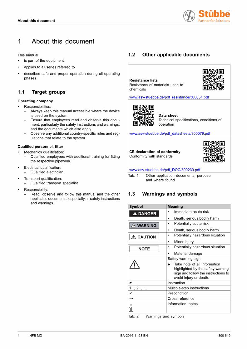
1.2 Other applicable documents
Resistance listsResistance of materials used tochemicals
www.asv-stuebbe.de/pdf_resistance/300051.pdf
Data sheetTechnical specifications, conditions ofoperation
www.asv-stuebbe.de/pdf_datasheets/300079.pdf
CE declaration of conformityConformity with standards
www.asv-stuebbe.de/pdf_DOC/300239.pdf
Tab. 1 Other application documents, purposeand where found
1.3 Warnings and symbols
Symbol Meaning
• Immediate acute risk
• Death, serious bodily harm
• Potentially acute risk
• Death, serious bodily harm
• Potentially hazardous situation
• Minor injury
• Potentially hazardous situation
• Material damage
Safety warning sign
Take note of all informationhighlighted by the safety warningsign and follow the instructions toavoid injury or death.
Instruction
1. , 2. , … Multiple-step instructions
Precondition→ Cross reference
Information, notes
Tab. 2 Warnings and symbols
4 HFB MD BA-2016.11.28 EN 300 619
General safety instructions
2 General safety instructions
The manufacturer accepts no liability for damages causedby disregarding any of the documentation.
2.1 Intended use
The device measures or monitors the level of a liquid medium.The relay version switches off a consuming unit (e.g. pump) iflimit values are exceeded or not achieved. The limit values areadjustable.
• Device must only be used for monitoring filling level in liquidmedia.
• Only use the device with suitable media (→ resistancelists).
• Adhere to the operating limits (→ 10.1 Technical specifica-tions, Page 19).
2.2 General safety instructions
Observe the following regulations before carrying out anywork.
2.2.1 Obligations of the operating company
Safety-conscious operation
• Only operate the device if it is in perfect technical conditionand only use it as intended, staying aware of safety andrisks, and in adherence to the instructions in this manual.
• Ensure that the following safety aspects are observed andmonitored:– Intended use– Statutory or other safety and accident-prevention reg-
ulations– Safety regulations governing the handling of haz-
ardous substances– Applicable standards and guidelines in the country
where the pump is operated
• Make personal protective equipment available.
Qualified personnel
• Make sure all personnel tasked with work on the devicehave read and understood this manual and all other appli-cable documents, especially the safety, maintenance andrepair information, before they start any work.
• Organize responsibilities, areas of competence and thesupervision of personnel.
• The following work should be carried out by specialist tech-nicians only:– Installation, repair and maintenance work– Work on the electrical system
• Make sure that trainee personnel only work on the deviceunder supervision of specialist technicians.
2.2.2 Obligations of personnel
Only complete work on the device if the following requirementsare met:
• System is empty
• System has been flushed
• System is depressurized
• System has cooled down
• System is secured against being switched back on again
• Do not make any modifications to the device
2.3 Specific hazards
2.3.1 Hazardous media
• When handling hazardous media, observe the safety reg-ulations for the handling of hazardous substances.
• Use personal protective equipment when carrying out anywork on the device.
• Collect leaking pumped liquid and residues in a safe man-ner and dispose of in accordance with environmental reg-ulations.
300 619 BA-2016.11.28 EN HFB MD 5
Layout and Function
3 Layout and Function
3.1 Type plate
HFB MD FlexFüllstandssensorMessbereich 0-0,5 bar
18-30V DCId.No.140557
Material PE / FPM
1304-05371
1
2
3
452 Relais
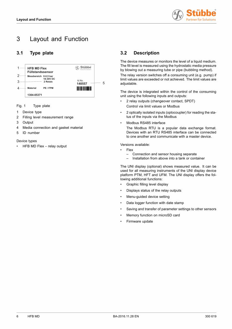
Fig. 1 Type plate
1 Device type
2 Filling level measurement range
3 Output
4 Media connection and gasket material
5 ID number
Device types
• HFB MD Flex – relay output
3.2 Description
The device measures or monitors the level of a liquid medium.The fill level is measured using the hydrostatic media pressureby blowing out a measuring tube or pipe (bubbling method).
The relay version switches off a consuming unit (e.g. pump) iflimit values are exceeded or not achieved. The limit values areadjustable.
The device is integrated within the control of the consumingunit using the following inputs and outputs:
• 2 relay outputs (changeover contact, SPDT)
Control via limit values or Modbus
• 2 optically isolated inputs (optocoupler) for reading the sta-tus of the inputs via the Modbus
• Modbus RS485 interface
The Modbus RTU is a popular data exchange format.Devices with an RTU RS485 interface can be connectedto one another and communicate with a master device.
Versions available:
• Flex– Connection and sensor housing separate– Installation from above into a tank or container
The UNI display (optional) shows measured value. It can beused for all measuring instruments of the UNI display deviceplatform PTM, HFT and UFM. The UNI display offers the fol-lowing additional functions:
• Graphic filling level display
• Displays status of the relay outputs
• Menu-guided device setting
• Data logger function with date stamp
• Saving and transfer of parameter settings to other sensors
• Memory function on microSD card
• Firmware update
6 HFB MD BA-2016.11.28 EN 300 619
Layout and Function
3.3 Layout
3.3.1 Housing and sensor
3
7
52
1
4
6
8
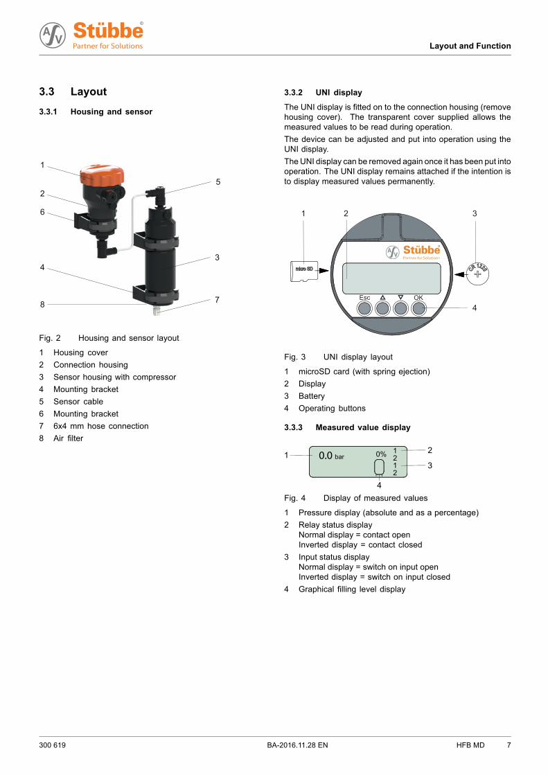
Fig. 2 Housing and sensor layout
1 Housing cover
2 Connection housing
3 Sensor housing with compressor
4 Mounting bracket
5 Sensor cable
6 Mounting bracket
7 6x4 mm hose connection
8 Air filter
3.3.2 UNI display
The UNI display is fitted on to the connection housing (removehousing cover). The transparent cover supplied allows themeasured values to be read during operation.
The device can be adjusted and put into operation using theUNI display.
TheUNI display can be removed again once it has been put intooperation. The UNI display remains attached if the intention isto display measured values permanently.
Esc OK
1 2 3
4
Fig. 3 UNI display layout
1 microSD card (with spring ejection)
2 Display
3 Battery
4 Operating buttons
3.3.3 Measured value display
1 2
30.0 bar
1 2 0%
4
12
Fig. 4 Display of measured values
1 Pressure display (absolute and as a percentage)
2 Relay status displayNormal display = contact openInverted display = contact closed
3 Input status displayNormal display = switch on input openInverted display = switch on input closed
4 Graphical filling level display
300 619 BA-2016.11.28 EN HFB MD 7
Transport, Storage and Disposal
4 Transport, Storage and Disposal
4.1 Unpacking and inspection on delivery
1. Unpack the device when received and inspect it for trans-port damage and completeness.
2. Check that the information on the type plate agrees withthe order/design data.
3. Report any transport damage to the manufacturer immedi-ately.
4. If fitted immediately: dispose of packaging material accord-ing to local regulations.– If fitted at a later point: leave device in its original pack-
aging.
4.2 Transportation
Device should preferably be transported in the originalpackaging.
4.3 Storage
NOTE
Material damage due to inappropriate storage!
Store the device properly.
1. Make sure the storage room meets the following condi-tions:– Dry– Frost-free– Vibration-free– Not in direct sunlight– Storage temperature +10 °C to +60 °C
2. Device should preferably be stored in the original packag-ing.
4.4 Disposal
Plastic parts can be contaminated by poisonous or radioac-tive media to such an extent that cleaning will not be suffi-cient.
WARNING
Risk of poisoning and environmental damage frommedium.
Use personal protective equipment when carrying out anywork on the device.
Prior to the disposal of the device: Neutralize residues ofmedium in the device.
1. Remove battery and dispose of in accordance with localregulations.
2. Remove electronic parts and dispose of in accordance withlocal regulations.
3. Dispose of plastic parts in accordance with local regula-tions.
8 HFB MD BA-2016.11.28 EN 300 619
Installation and connection
5 Installation and connection
5.1 Check operating conditions
1. Ensure the required operating conditions are met:– Resistance of body and seal material to the medium
(→ resistance lists).– Media temperature (→ 10.1 Technical specifications,
Page 19).– Working pressure (→ 10.1 Technical specifications,
Page 19).
2. Consult with the manufacturer regarding any other use ofthe device.
5.2 Install device
Tank has been properly prepared.
WARNING
Risk of injury and poisoning due to medium spraying out.
Use personal protective equipment when carrying out anywork on the device.
1. If present, mount bracket for connection housing and sen-sor housing.
2. Secure connection housing and sensor housing in bracket.
3. Mount tank lead-through on the tank.
4. Attach hose to sensor housing.
5. Guide hose through the tank lead-through.
6. Mount additional weight (→ Data sheet)– Guide hose through hole in additional weight– Push in nipple in hose– Withdraw hose
7. Lower hose with additional weight to the bottom of the tank.– The end of the hose must not touch the base– Tighten fitting on tank lead-through (finger-tight)
5.3 Electrical connection of device
Device is connected to the process pipework.
Power supply is switched off and secured against beingswitched back on again.
Cable without shielding can be used to connect the device.If electromagnetic interference is anticipated, then useshielded cable.
Terminal strips are pluggable.
DANGER
Risk of electrocution
All electrical work must be carried out by qualified electri-cians only.
Switch off system power supply and secure it against beingswitched back on again.
1. Unscrew the housing cover from the connection housing,remove UNI display if required.
2. Guide the connection cable through the cable glands andconnect:– Cable (→ Data sheet).– Connection diagram (→ 10.4 Modbus RTU connection
plan, Page 19).
3. Tighten the cable glands securely.
4. Insert jumper– If the bus cable ends at this device, plug jumper on to
“ON”– If the bus cable does not end at this device or is
extended, plug jumper on to “OFF”(→ 10.5 Modbus RTU termination, Page 20).
5. Screw on the housing cover.
6. Use earthed Modbus power supply (power supply unit withPE connection).
300 619 BA-2016.11.28 EN HFB MD 9
Operation
6 Operation
NOTE
Changing parameters affects the switching outputs imme-diately.
Make sure that changing a parameter does not trigger amalfunction (e.g. a pump running dry).
When switching on the device, all relay contacts are openfor 3 s (NO).
After this the relay contacts assume the status which cor-responds with the setting and the measured values.
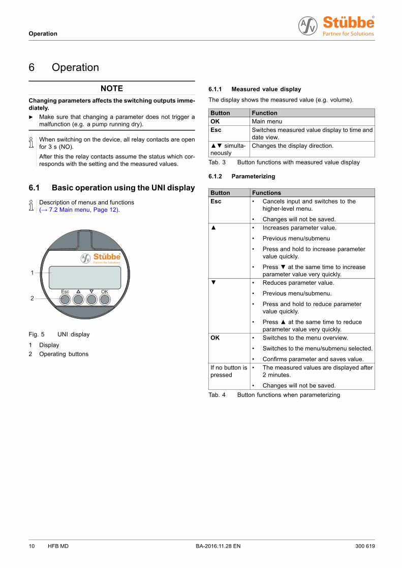
6.1 Basic operation using the UNI display
Description of menus and functions(→ 7.2 Main menu, Page 12).
Esc OK
1
2
Fig. 5 UNI display
1 Display
2 Operating buttons
6.1.1 Measured value display
The display shows the measured value (e.g. volume).
Button Function
OK Main menu
Esc Switches measured value display to time anddate view.
▲▼ simulta-neously
Changes the display direction.
Tab. 3 Button functions with measured value display
6.1.2 Parameterizing
Button Functions
Esc • Cancels input and switches to thehigher-level menu.
• Changes will not be saved.▲ • Increases parameter value.
• Previous menu/submenu
• Press and hold to increase parametervalue quickly.
• Press ▼ at the same time to increaseparameter value very quickly.
▼ • Reduces parameter value.
• Previous menu/submenu.
• Press and hold to reduce parametervalue quickly.
• Press ▲ at the same time to reduceparameter value very quickly.
OK • Switches to the menu overview.
• Switches to the menu/submenu selected.
• Confirms parameter and saves value.
If no button ispressed
• The measured values are displayed after2 minutes.
• Changes will not be saved.
Tab. 4 Button functions when parameterizing
10 HFB MD BA-2016.11.28 EN 300 619
Operation
6.2 Initial start-up with UNI display
The UNI display can be removed again once it has beenput into operation.
The UNI display remains attached if the intention is to dis-play measured values permanently.
If the display is upside down, press ▲▼ buttons simulta-neously.
Device is installed properly.
Device is connected properly with the power supply andready for operation.
1. Unscrew the housing cover.
2. Insert UNI display on to the electronic equipment (whiteplug-in location).
3. Configure device (→ 7.2 Main menu, Page 12).
4. Remove UNI display if necessary.
5. Screw on housing cover or transparent cover.
6.3 Managing several devices
Using the UNI display and microSD card, parameter setscan be transferred between devices or archived on a PC.
All microSD cards or microSDHC cards with FAT32 format-ting are supported. Files must be maintained in the masterdirectory.
Files should be named in Format 8.3 (e.g. PARA_1.ASV),otherwise only an abbreviated file name is displayed.
The memory function always names the filesSTUEBBE.ASV. If a STUEBBE.ASV file already exists onthe microSD card, then this file is overwritten.
6.3.1 Backing up parameter sets
1. Save the parameter set from the device on to the microSDcard (→ 7.7 Service menu, Page 15).
2. Insert the microSD card into the PC, then transfer andarchive the STUEBBE.ASV file.
6.3.2 Parameterizing several devices
1. Parameterize the first device (→ 7.2 Mainmenu, Page 12).
2. Save the parameter set from the device on to the microSDcard (→ 7.7 Service menu, Page 15).
3. Attach the UNI display, with the microSD cards inserted, onto the next device.
4. Save the parameter set from the microSD card on to thedevice (→ 7.7 Service menu, Page 15).
6.4 Reading the data logger
Series of measurements can be created and read using theUNI display and microSD card.
1. Insert the microSD card in a UNI display and attach the UNIdisplay to the device.
2. Set up the data logger function (→ 7.6 Diagnostics menu,Page 14).
3. Remove the microSD card and read the log file (csv format)on the PC.
6.5 Updating firmware
Current sensor firmware or UNI display firmware can beobtained via the Internet(→ www.asv-stuebbe.com/service/downloads).
In the event that the updating is interrupted(→ 9.1.1 Fixingsoftware loading errors, Page 18).
1. Download the latest version of the sensor firmware(e. g. HFB_Vxxx.HEX) and UNI display firmware(UNI_Vxxx.HEX) from the Internet and save on themicroSD card.
2. Insert the microSD card in a UNI display and attach the UNIdisplay to the device.
3. Save sensor firmware or UNI display firmware from themicroSD card on to the device (→ 7.7 Service menu,Page 15).
4. Observe release notes. If “reset factory settings” is neces-sary:– Note all parameters.– Perform “reset factory settings” (→ 7.2 Main menu,
Page 12).– Reset the device (→ 7.7 Service menu, Page 15).
5. Check date and time, and reset if necessary (→ 7.3 Basicsettings menu, Page 12).
300 619 BA-2016.11.28 EN HFB MD 11
Menus and functions
7 Menus and functions
7.1 Measured value display
The display shows the measured value (e.g. volume).
Button Function
OK Main menu
Esc Switches measured value display to time anddate view.
▲▼ simulta-neously
Changes the display direction.
Tab. 5 Button function with measured value display
7.2 Main menu
Main menu Function
Basic settings Performs basic settings(→ 7.3 Basic settings menu, Page 12).
Output Adjusts the behavior of the outputs(→ 7.4 Output menu, Page 13).
Display Sets the display options(→ 7.5 Display menu, Page 14).
Diagnostics Checks the diagnostics functions(→ 7.6 Diagnostics menu, Page 14).
Service Performs the service functions(→ 7.7 Service menu, Page 15).
Tab. 6 Main menu
7.3 Basic settings menu
Submenuvalues
Function
Language
DeutschEnglishFrançaisEspañolItaliano
Sets the operating language
Lighting
automatic The display lighting switches onautomatically for 15 seconds:
• if the display value of the pressurechanges by 5%
using any button The display lighting switches on for 15s each time a button is pressed.
off Display lighting is always off.on Display lighting is always on.
Integration time
Submenuvalues
Function
0 … 60 s Sets the measurement interval for thepressure sensor.An average is calculated and displayedusing the measurement interval. Thisremoves the effect of short-termpressure fluctuations.A long integration time delays thereaction to pressure fluctuations.
Calibration
Basic correction The current pressure is set as thereference pressure (0 bar). All othermeasures then refer to this referencepressure.
min. calibration Setting % display pressure. The valueset is displayed as “0%”:
▲▼ – sets pressure value for 0%
OK – accepts setting
max. calibration Setting % display pressure. The valueset is displayed as “100%”:
▲▼ – sets pressure value for100%
OK – accepts setting
Specific gravity of medium
xxxx.yyy kg/m3 ▲▼ – sets the specific gravity ofmedium to be measured.
OK – accepts setting
Volume expansion
xxx.y 10-5/K ▲▼ – sets heat-related volumeexpansion of medium to bemeasured.
OK – accepts setting
Tank volumexx.y m3
xxxxx l▲▼ – sets volume of tank to bemeasured
OK – accepts settingxxxx mm ▲▼ – sets tank height.
OK – accepts setting
100% ▲▼ – tank height = 100%(yes/no).
OK – accepts setting
Container shape
LinearSpherical tankHorizontal tank
▲▼ – sets tank shape.
OK – accepts setting
▲▼ – sets number of tanks (1 …5) for accumulation tanks.
OK – accepts setting
12 HFB MD BA-2016.11.28 EN 300 619
Menus and functions
Submenuvalues
Function
Time
DD.MM.YYYYHH:MM
Display/setting of date and time.The first position in the date isunderlined.
▲▼ – adjusts value
OK – accepts value and sets nextposition
After setting minutes, OK returnsyou to the basic settings menu
Modbus settings
Setting baud rate.
▲▼ – selects value between 2400and 38400.
OK – accepts setting
Interface
All busparticipants musthave the samesettings for baudrate / parity
Setting paritySame parity 1 stop bitNo parity 2 stop bits
▲▼ – adjusts value.
OK – accepts setting
Address
All busparticipants musthave differentaddresses
Setting slave addressThe first position in the address isunderlined.
▲▼ – selects value between 1and 247.
OK – accept value and set nextposition.
After setting the last number, OKreturns you to the basic settingsmenu.
Tab. 7 Basic settings menu
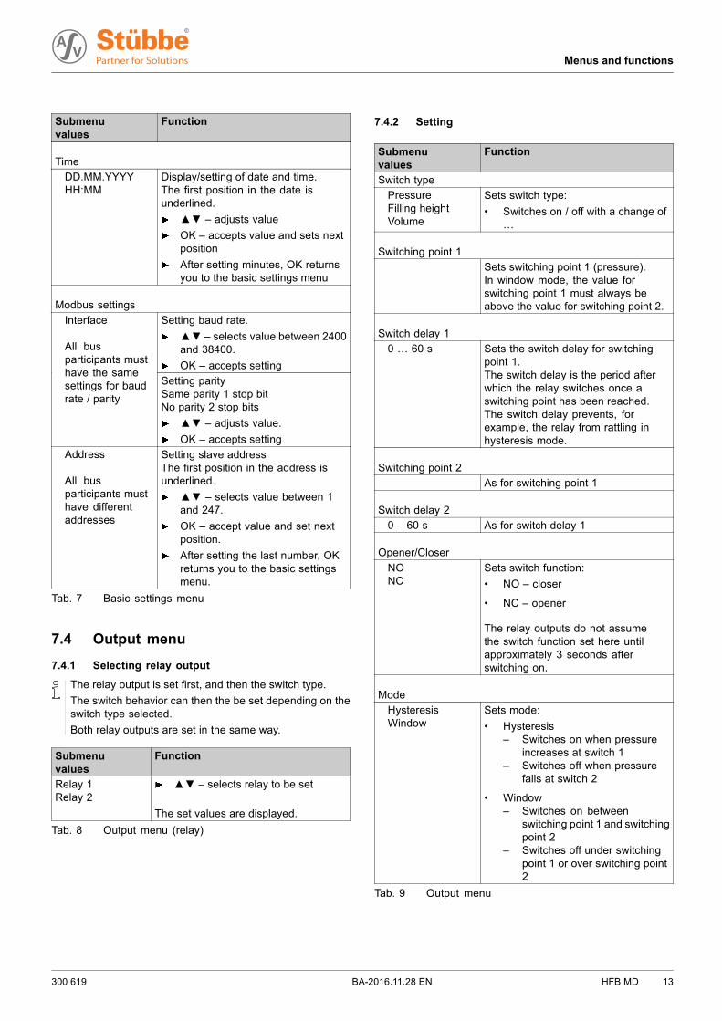
7.4 Output menu
7.4.1 Selecting relay output
The relay output is set first, and then the switch type.
The switch behavior can then the be set depending on theswitch type selected.
Both relay outputs are set in the same way.
Submenuvalues
Function
Relay 1Relay 2
▲▼ – selects relay to be set
The set values are displayed.
Tab. 8 Output menu (relay)
7.4.2 Setting
Submenuvalues
Function
Switch type
PressureFilling heightVolume
Sets switch type:
• Switches on / off with a change of…
Switching point 1
Sets switching point 1 (pressure).In window mode, the value forswitching point 1 must always beabove the value for switching point 2.
Switch delay 1
0 … 60 s Sets the switch delay for switchingpoint 1.The switch delay is the period afterwhich the relay switches once aswitching point has been reached.The switch delay prevents, forexample, the relay from rattling inhysteresis mode.
Switching point 2
As for switching point 1
Switch delay 2
0 – 60 s As for switch delay 1
Opener/Closer
NONC
Sets switch function:
• NO – closer
• NC – opener
The relay outputs do not assumethe switch function set here untilapproximately 3 seconds afterswitching on.
Mode
HysteresisWindow
Sets mode:
• Hysteresis– Switches on when pressure
increases at switch 1– Switches off when pressure
falls at switch 2
• Window– Switches on between
switching point 1 and switchingpoint 2
– Switches off under switchingpoint 1 or over switching point2
Tab. 9 Output menu
300 619 BA-2016.11.28 EN HFB MD 13
Menus and functions
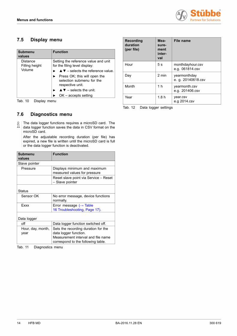
7.5 Display menu
Submenuvalues
Function
DistanceFilling heightVolume
Setting the reference value and unitfor the filing level display:
▲▼ – selects the reference value.
Press OK; this will open theselection submenu for therespective unit.
▲▼ – selects the unit.
OK – accepts setting
Tab. 10 Display menu
7.6 Diagnostics menu
The data logger functions requires a microSD card. Thedata logger function saves the data in CSV format on themicroSD card.
After the adjustable recording duration (per file) hasexpired, a new file is written until the microSD card is fullor the data logger function is deactivated.
Submenuvalues
Function
Slave pointer
Pressure Displays minimum and maximummeasured values for pressure
Reset slave point via Service – Reset– Slave pointer
Status
Sensor OK No error message, device functionsnormally.
Exxx Error message (→ Table16 Troubleshooting, Page 17).
Data logger
off Data logger function switched off.
Hour, day, month,year
Sets the recording duration for thedata logger function.Measurement interval and file namecorrespond to the following table.
Tab. 11 Diagnostics menu
Recordingduration(per file)
Mea-sure-mentinter-val
File name
Hour 5 s monthdayhour.csve.g. 061814.csv
Day 2 min yearmonthdaye. g. 20140618.csv
Month 1 h yearmonth.csve.g. 201406.csv
Year 1.8 h year.csve.g 2014.csv
Tab. 12 Data logger settings
14 HFB MD BA-2016.11.28 EN 300 619
Menus and functions
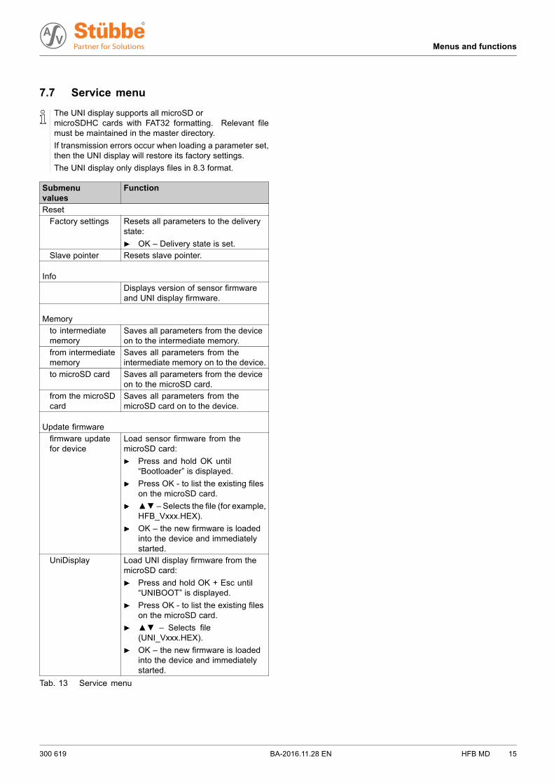
7.7 Service menu
The UNI display supports all microSD ormicroSDHC cards with FAT32 formatting. Relevant filemust be maintained in the master directory.
If transmission errors occur when loading a parameter set,then the UNI display will restore its factory settings.
The UNI display only displays files in 8.3 format.
Submenuvalues
Function
Reset
Factory settings Resets all parameters to the deliverystate:
OK – Delivery state is set.
Slave pointer Resets slave pointer.
Info
Displays version of sensor firmwareand UNI display firmware.
Memory
to intermediatememory
Saves all parameters from the deviceon to the intermediate memory.
from intermediatememory
Saves all parameters from theintermediate memory on to the device.
to microSD card Saves all parameters from the deviceon to the microSD card.
from the microSDcard
Saves all parameters from themicroSD card on to the device.
Update firmware
firmware updatefor device
Load sensor firmware from themicroSD card:
Press and hold OK until“Bootloader” is displayed.
Press OK - to list the existing fileson the microSD card.
▲▼ – Selects the file (for example,HFB_Vxxx.HEX).
OK – the new firmware is loadedinto the device and immediatelystarted.
UniDisplay Load UNI display firmware from themicroSD card:
Press and hold OK + Esc until“UNIBOOT” is displayed.
Press OK - to list the existing fileson the microSD card.
▲▼ – Selects file(UNI_Vxxx.HEX).
OK – the new firmware is loadedinto the device and immediatelystarted.
Tab. 13 Service menu
300 619 BA-2016.11.28 EN HFB MD 15
Maintenance
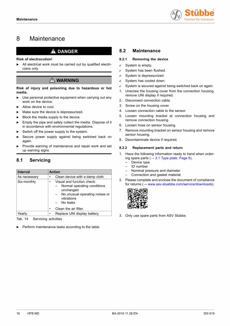
8 Maintenance
DANGER
Risk of electrocution!
All electrical work must be carried out by qualified electri-cians only.
WARNING
Risk of injury and poisoning due to hazardous or hotmedia.
Use personal protective equipment when carrying out anywork on the device.
Allow device to cool.
Make sure the device is depressurized.
Block the media supply to the device.
Empty the pipe and safely collect the media. Dispose of itin accordance with environmental regulations.
Switch off the power supply to the system.
Secure power supply against being switched back onagain.
Provide warning of maintenance and repair work and setup warning signs.
8.1 Servicing
Interval Action
As necessary • Clean device with a damp cloth.
Six-monthly • Visual and function check:– Normal operating conditions
unchanged– No unusual operating noises or
vibrations– No leaks
• Clean the air filter.
Yearly • Replace UNI display battery.
Tab. 14 Servicing activities
Perform maintenance tasks according to the table.
8.2 Maintenance
8.2.1 Removing the device
System is empty.
System has been flushed.
System is depressurized.
System has cooled down.
System is secured against being switched back on again.
1. Unscrew the housing cover from the connection housing,remove UNI display if required.
2. Disconnect connection cable.
3. Screw on the housing cover.
4. Loosen connection cable to the sensor.
5. Loosen mounting bracket at connection housing andremove connection housing.
6. Loosen hose on sensor housing.
7. Remove mounting bracket on sensor housing and removesensor housing.
8. Decontaminate device if required.
8.2.2 Replacement parts and return
1. Have the following information ready to hand when order-ing spare parts (→ 3.1 Type plate, Page 6).– Device type– ID number– Nominal pressure and diameter– Connection and gasket material
2. Please complete and enclose the document of compliancefor returns (→ www.asv-stuebbe.com/service/downloads).
3. Only use spare parts from ASV Stübbe.
16 HFB MD BA-2016.11.28 EN 300 619
Troubleshooting
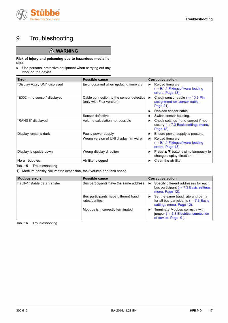
9 Troubleshooting
WARNING
Risk of injury and poisoning due to hazardous media liq-uids!
Use personal protective equipment when carrying out anywork on the device.
Error Possible cause Corrective action
“Display Vx.yy UNI” displayed Error occurred when updating firmware Reload firmware(→ 9.1.1 Fixingsoftware loadingerrors, Page 18).
Cable connection to the sensor defective(only with Flex version)
Check sensor cable (→ 10.6 Pinassignment on sensor cable,Page 21).
Replace sensor cable.
“E002 – no sensor” displayed
Sensor defective Switch sensor housing.
“RANGE” displayed Volume calculation not possible Check settings1) and correct if nec-essary (→ 7.3 Basic settings menu,Page 12).
Faulty power supply Ensure power supply is present.Display remains dark
Wrong version of UNI display firmware Reload firmware(→ 9.1.1 Fixingsoftware loadingerrors, Page 18).
Display is upside down Wrong display direction Press▲▼ buttons simultaneously tochange display direction.
No air bubbles Air filter clogged Clean the air filter.
Tab. 15 Troubleshooting
1) Medium density, volumetric expansion, tank volume and tank shape
Modbus errors Possible cause Corrective action
Bus participants have the same address Specify different addresses for eachbus participant (→ 7.3 Basic settingsmenu, Page 12).
Bus participants have different baudrates/parities
Set the same baud rate and parityfor all bus participants (→ 7.3 Basicsettings menu, Page 12).
Faulty/instable data transfer
Modbus is incorrectly terminated Terminate Modbus correctly withjumper (→ 5.3 Electrical connectionof device, Page 9 ).
Tab. 16 Troubleshooting
300 619 BA-2016.11.28 EN HFB MD 17
Troubleshooting
9.1 Troubleshooting
9.1.1 Fixingsoftware loading errors
If an error occurs when updating the sensor firmware orthe UNI display firmware (e.g. power failure), it may not bepossible to call up the “Update firmware” menu.
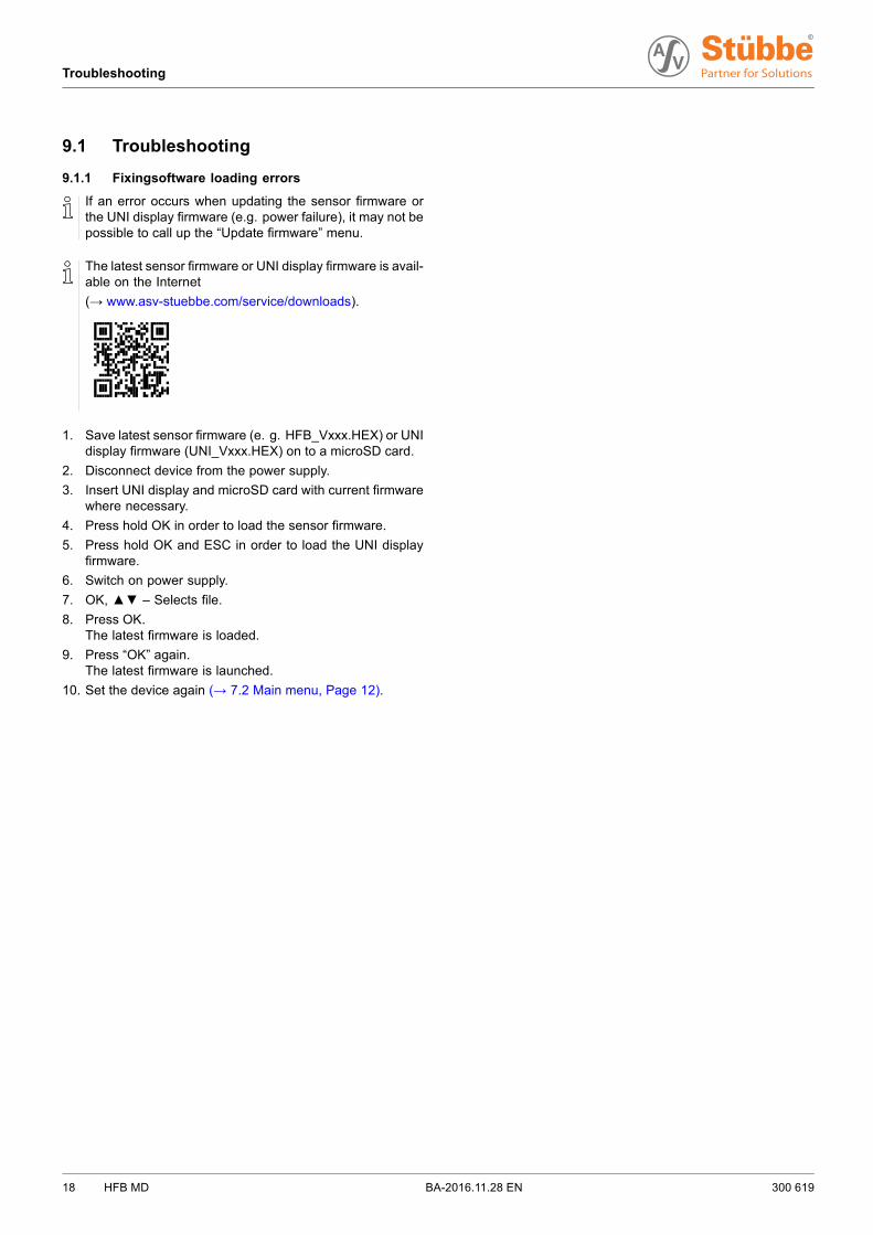
The latest sensor firmware or UNI display firmware is avail-able on the Internet
(→ www.asv-stuebbe.com/service/downloads).
1. Save latest sensor firmware (e. g. HFB_Vxxx.HEX) or UNIdisplay firmware (UNI_Vxxx.HEX) on to a microSD card.
2. Disconnect device from the power supply.
3. Insert UNI display and microSD card with current firmwarewhere necessary.
4. Press hold OK in order to load the sensor firmware.
5. Press hold OK and ESC in order to load the UNI displayfirmware.
6. Switch on power supply.
7. OK, ▲▼ – Selects file.
8. Press OK.The latest firmware is loaded.
9. Press “OK” again.The latest firmware is launched.
10. Set the device again (→ 7.2 Main menu, Page 12).
18 HFB MD BA-2016.11.28 EN 300 619
Appendix
10 Appendix
10.1 Technical specifications
Technical data (→ Data sheet).
10.2 Dimensions
Dimensions (→ Data sheet).
10.3 Accessories
Description Ident. number
UNI display
• Display and control unit
• with PA transparent cover for theconnection housing
• Languages: DE, EN, FR, ES, IT
144153
Battery, CR1220, 3 V 144328
Memory card, Micro SD 144329
HFB PVDF additional weight 148196
6x4 PE hose, maximum length 50 m 148200
6x4 PTFE hose, maximum length 5 m 148186
Tank lead-through 2" PP EPDM 148157
Tank lead-through 2" PP FPM 148158
Tank lead-through 2" PVDF EPDM 148149
Tank lead-through 2" PVDF FPM 148150
Tab. 17 Accessories
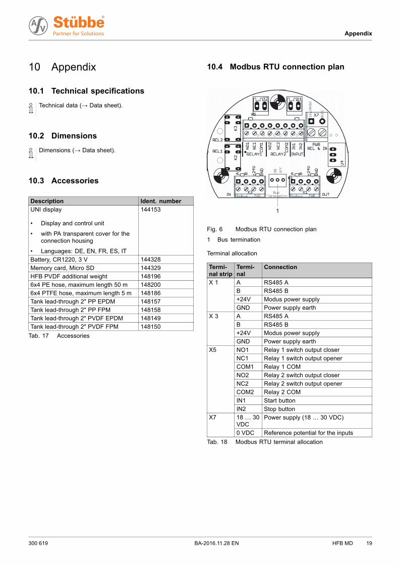
10.4 Modbus RTU connection plan
1
Fig. 6 Modbus RTU connection plan
1 Bus termination
Terminal allocation
Termi-nal strip
Termi-nal
Connection
A RS485 A
B RS485 B
+24V Modus power supply
X 1
GND Power supply earth
A RS485 A
B RS485 B
+24V Modus power supply
X 3
GND Power supply earth
NO1 Relay 1 switch output closer
NC1 Relay 1 switch output opener
COM1 Relay 1 COM
NO2 Relay 2 switch output closer
NC2 Relay 2 switch output opener
COM2 Relay 2 COM
IN1 Start button
X5
IN2 Stop button
18 … 30VDC
Power supply (18 … 30 VDC)X7
0 VDC Reference potential for the inputs
Tab. 18 Modbus RTU terminal allocation
300 619 BA-2016.11.28 EN HFB MD 19
Appendix
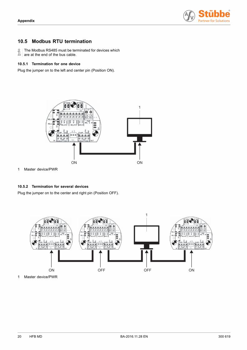
10.5 Modbus RTU termination
The Modbus RS485 must be terminated for devices whichare at the end of the bus cable.
10.5.1 Termination for one device
Plug the jumper on to the left and center pin (Position ON).
1
ON ON
1 Master device/PWR
10.5.2 Termination for several devices
Plug the jumper on to the center and right pin (Position OFF).
1
ON OFFOFF ON
1 Master device/PWR
20 HFB MD BA-2016.11.28 EN 300 619
Appendix
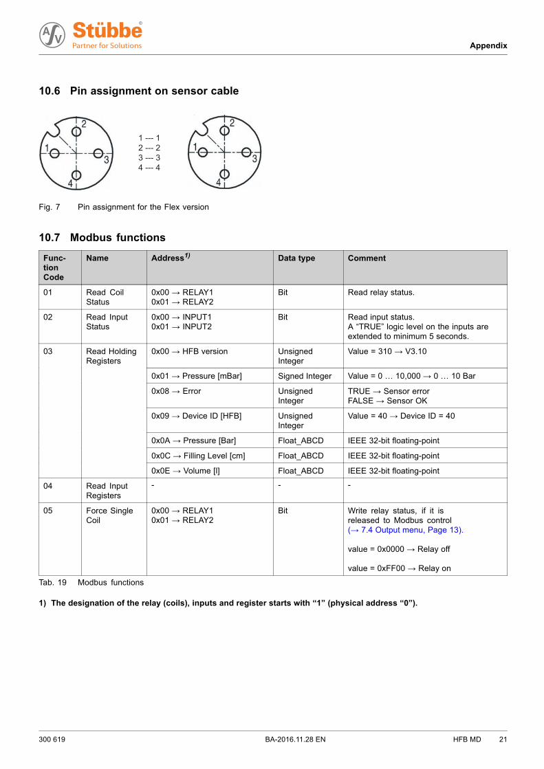
10.6 Pin assignment on sensor cable
1 --- 12 --- 23 --- 34 --- 4
Fig. 7 Pin assignment for the Flex version
10.7 Modbus functions
Func-tionCode
Name Address1) Data type Comment
01 Read CoilStatus
0x00 → RELAY10x01 → RELAY2
Bit Read relay status.
02 Read InputStatus
0x00 → INPUT10x01 → INPUT2
Bit Read input status.A “TRUE” logic level on the inputs areextended to minimum 5 seconds.
0x00 → HFB version UnsignedInteger
Value = 310 → V3.10
0x01→ Pressure [mBar] Signed Integer Value = 0 … 10,000→ 0 … 10 Bar
0x08 → Error UnsignedInteger
TRUE → Sensor errorFALSE → Sensor OK
0x09→ Device ID [HFB] UnsignedInteger
Value = 40 → Device ID = 40
0x0A→ Pressure [Bar] Float_ABCD IEEE 32-bit floating-point
0x0C→ Filling Level [cm] Float_ABCD IEEE 32-bit floating-point
03 Read HoldingRegisters
0x0E → Volume [l] Float_ABCD IEEE 32-bit floating-point
04 Read InputRegisters
- - -
05 Force SingleCoil
0x00 → RELAY10x01 → RELAY2
Bit Write relay status, if it isreleased to Modbus control(→ 7.4 Output menu, Page 13).
value = 0x0000 → Relay off
value = 0xFF00 → Relay on
Tab. 19 Modbus functions
1) The designation of the relay (coils), inputs and register starts with “1” (physical address “0”).
300 619 BA-2016.11.28 EN HFB MD 21
Appendix
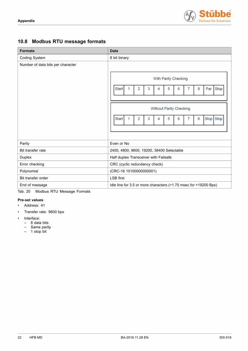
10.8 Modbus RTU message formats
Formats Data
Coding System 8 bit binary
Number of data bits per character
Parity Even or No
Bit transfer rate 2400, 4800, 9600, 19200, 38400 Selectable
Duplex Half duplex Transceiver with Failsafe
Error checking CRC (cyclic redundancy check)
Polynomial (CRC-16 10100000000001)
Bit transfer order LSB first
End of message Idle line for 3.5 or more characters (>1.75 msec for >19200 Bps)
Tab. 20 Modbus RTU Message Formats
Pre-set values
• Address: 41
• Transfer rate: 9600 bps
• Interface:– 8 data bits– Same parity– 1 stop bit
22 HFB MD BA-2016.11.28 EN 300 619