Embed Size (px)
Citation preview
80.30-1us
FNK 050 · FNK 100· Operating pressure up to 145 psi
· Nominal flow rate up to 33 gpm
· Cooling capacity up to 45 kW
F i l te r Coo l ing Un i t s
Descr i p t ion
Ch arac ter i s t i c s
ApplicationReturn-flow or off-line filter in hydraulic systems with water cooling.
GeneralHigh power densities in modern hydraulic systems require on one hand excellent cleanliness classes of the oil and on the other hand powerful cooling systems. The ARGO-HYTOS filter cooling unit FNK meets both demands on smallest installation space.
Performance featuresProtection against wear: By means of filter elements that meet even the the highest demands regarding cleanliness classes.
Cooling: Efficient discharge of large heat flow volumes by means of a powerful cooler.
Assembly and operating modeOil that has to be cooled is first cleaned over a fine filter element and then flows – through a check-valve and the high-performance tubular cooler – in cooled-down condition into the tank.Monitoring of filter clogging is effected by an optionally available diffe-rential pressure indicator. The integrated by-pass valve protects the filter element in cold start against increasing differential pressures.
Special design featuresBy combination of fine filter and cooler in one unit the necessary space is considerably reduced compared to conventional solutions. This also results in less assembling and piping.The filter element is hooked to the cover and is pulled upwards when it has to be changed. Because of the cover design the filter element can be changed almost without losing any oil. An integrated check valve prevents draining of oil from the tank when assembling the filter cooling unit below the oil level.With maintenance work at the cooler it simply can be removed from the housing after removing the water connections.
Filter elementsFlow direction from outside to center. The star-shaped pleating of the filter results in:• largefiltersurfaces• lowpressuredrop• highdirtholdingcapacities• longservicelife
Filter maintenanceBy using a clogging indicator the correct moment for maintenance is stated and guarantees the optimum utilization of the filter.The cooler is maintenance-free up to a large extent.Unfavourable water qualities (e.g. high water hardness and PH-value) and high temperatures may lead to sediments in the water pipes and/or the cooler surface. The water quality therefore has to be controlled regularly and if necessary improved. For cleaning of the water pipes the cover of the cooler can be removed. The maintenance instructions give detailed information on the mainte-nance of the cooler.
Materials:Filter housing FNK 050: GG, Filter head: SteelFilter housing FNK 100: Aluminum alloyFilter cover: GGCooler cover: GGCooler catalyst tube: SteelSeals: NBR (FKM on request)Filter media: EXAPOR®MAX 2 – inorganic multi-layer microfibre web
AccessoriesElectrical and optical clogging indicators are available. Dimensions and technical data see catalog sheet 60.30.
Operating pressureMax. 145 psi
Cooling capacityUp to 45 kW
Nominal flow rateUp to 33 gpm(see Selection Chart, column 3)
Filter fineness5 µm(c) β-values according to ISO 16889(see Selection Chart, column 5 and Diagram Dx)
Dirt-holding capacityValues in g test dust ISO MTD according to ISO 16889(see Selection Chart, column 6)
Hydraulic fluidsMineral oil and biodegradable fluids(HEES and HETG, see info-sheet 00.20)
Temperature range of fluids-22 °F … +212 °F (temporary -40 °F ... +248 °F)
Mounting positionFilter preferably vertical and/or cooler horizontal
ConnectionThreaded ports according to ISO 228 or DIN 13.Sizes see Selection Chart, column 7.
Se l ec t ion Recommendat ions
1. Selection of the filter cooling unit according to the cooling performance chart
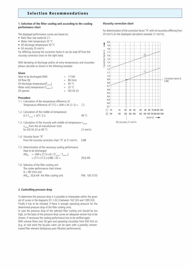
The displayed performance curves are based on:• Ratioflowratewater/oil2:1• Waterinlettemperature25°C• Oildischargetemperature50°C• Oilviscosity35mm²/sFor differing viscosity the correction factor A can be read off from the viscosity correction chart on the right hand.
With deviating oil discharge and/or oil entry temperatures and viscosities please calculate as shown in the following example:
GivenHeat to be discharged (AW) = 17 kWOil flow (Q) = 80 l/minOil discharge temperature(Toil out) = 45 °CWater entry temperature (Twater in) = 25 °COil species = ISO VG 32
Procedure1.1. Calculation of the temperature difference ∆T Temperature difference ∆T (°C) = (AW x 34,1) / Q = 7,2 1.2. Calculation of the middle oil temperature (2 x Toil out + ∆T) / 2 @ 49 °C
1.3. Calculation of the viscosity with middle oil temperature νactual
νactual from the oil manufacturer chart forISOVG32at49°C: 21mm²/s 1.4. Viscosity factor “A” Fromtheviscositycorrectionchart“A”at21mm²/s: 0,88
1.5. Determination of the necessary cooling performance Heat to be discharged AWeff. = (AW x 27,5 x A) / (Toil out - Twater in) = (17 x 27,5 x 0,88) / 20 = 20,6 kW
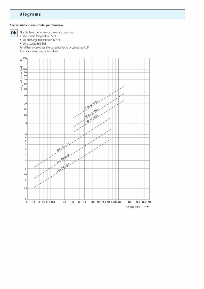
1.6. Selection of the filter cooling unit The cooler performance chart shows Q = 80 l/min and AWeff. 20,6 kW the filter cooling unit: FNK 100-3153
2. Controlling pressure drop
To determine the pressure drop it is possible to interpolate within the given set of curves in the diagrams D1.1-D2.3 between 162 SUS and 1395 SUS.Finally it has to be checked, if there is enough operating pressure for the determined pressure drop of the filter cooling units.In case the pressure drop of the selected filter cooling unit should be too high, on the basis of the pressure drop curves an adequate version has to be chosen. If necessary the cooling performance has to be verified again.With volume flows over 26 gpm and operating viscosities from 930 SUS on (e.g. at cold start) the by-pass valve can be open with a partially contam-inated filter element (temporary poor filtration performance).
Viscosity correction chart
For determination of the correction factor “A” with oil viscosities differing from 35mm²/s(inthedisplayedcalculationexample21mm²/s).
Corre
ctio
n fa
ctor
A
[mm²/s]
Oilviscosity21mm²/s
Correction factor A:0,88
Dk
Diagram s
Characteristic curves cooler performance
The displayed performance curves are based on:• Waterinlettemperature77°F• Oildischargetemperature122°F• Oilviscosity162SUSFor differing viscosities the correction factor A can be read off from the viscosity correction chart.
Flowrate[gpm]
Cool
ing
perfo
rman
ce[k
W]
1.1 1.3 1.6 1.8 2.1 2.4 2.6 4.0 5.3 6.6 7.9 10.6 13.2 15.9 18.5 21.1 23.8 26.4 39.6 52.8 66.0 79.3

D1.1
D1.2
D1.3 D2.3
D2.1
D2.2
Dx
Q[gpm]
Q[gpm]
Q[gpm] Q[gpm]
Q[gpm]
Q[gpm]
∆p[p
si]
∆p[p
si]
∆p[p
si]∆p
[psi]
∆p[p
si]∆p
[psi]
D iagrams
∆p-curves for complete filters in Selection Chart, column 4
Pressure drop as a function of the flow volume
Pressure drop as a function of the flow volume
Pressure drop as a function of the flow volume
Pressure drop as a function of the flow volume
Pressure drop as a function of the flow volume
Pressure drop as a function of the flow volume
Filter fineness curves in Selection Chart, column 5
Filtration ratio β as a function of particle size x obtained by the Multi-Pass-Test according to ISO 16889
Particlesizex[µm](forparticleslargerthan the given particle size x)
Filtr
atio
n ra
tion β
for p
artic
les
> x
[µm
]
Sepa
ratio
nef
ficie
ncy
[%]
The abbreviations represent the following β-values resp. finenesses:
For EXAPOR®MAX 2-Elements: 3EN2 = β3 (c) = 200 EXAPOR®MAX 2 5EN2 = β5 (c) = 200 EXAPOR®MAX 2 10EX2 = β10 (c) = 200 EXAPOR®MAX 2
For special applications, finenesses differing from these curves are also available by using special composed filter media.
In general the pressure drop increases in line with a larger cooler length.Exception:Due to lower distances of the disk sheets in the cooler the pressure drop of the FNK 050-1153 is higher than the one of the larger FNK 050-2153.
Due to lower distances of the disk sheets in the cooler the pressure drop of the FNK 100-3153 is higher than the one of the larger FNK 100-5153.
116.0
87.0
58.0
29.0
6.6 13.2 19.8 26.4 33.0 39.60
162 SUS
465 SUS
930 SUS
1390 SUS
116.0
87.0
58.0
29.0
6.6 13.2 19.8 26.4 33.0 39.60
162 SUS
465 SUS
930 SUS1390 SUS
116.0
87.0
58.0
29.0
6.6 13.2 19.8 26.4 33.0 39.60
162 SUS
465 SUS
930 SUS
1390 SUS
116.0
87.0
58.0
29.0
6.6 13.2 19.8 26.4 33.0 39.60
162 SUS
465 SUS
930 SUS1390 SUS
116.0
87.0
58.0
29.0
6.6 13.2 19.8 26.4 33.0 39.60
162 SUS
465 SUS
930 SUS
1390 SUS
116.0
87.0
58.0
29.0
6.6 13.2 19.8 26.4 33.0 39.60
162 SUS
465 SUS
930 SUS1390 SUS
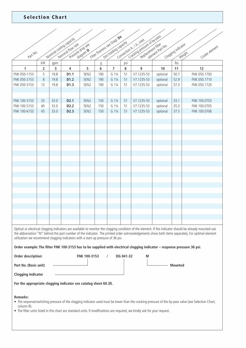
Se lec t ion Char t
Nominal cooling ca
pacity
Part No.
Clogging indicator
Cooler ele
ment
Nominal flow rate
Replacement filter
el
ement Pa
rt No.
Filter fi
neness se
e Diagr. D
x
1 2 3 4 5 6 7 8 9 10 11 12
kW
FNK 050-1153 5 19.8 D1.1 5EN2 190 G 1¼ 51 V7.1235-53 optional 50.7 FNK 050.1700FNK 050-2153 8 19.8 D1.2 5EN2 190 G 1¼ 51 V7.1235-53 optional 52.9 FNK 050.1710FNK 050-3153 13 19.8 D1.3 5EN2 190 G 1¼ 51 V7.1235-53 optional 57.3 FNK 050.1720 FNK 100-3153 33 33.0 D2.1 5EN2 150 G 1¼ 51 V7.1235-53 optional 33.1 FNK 100.0703FNK 100-5153 40 33.0 D2.2 5EN2 150 G 1¼ 51 V7.1235-53 optional 35.3 FNK 100.0705FNK 100-6153 45 33.0 D2.3 5EN2 150 G 1¼ 51 V7.1235-53 optional 37.5 FNK 100.0706
gpm g psi lbsDirt-
holding capacity
Connection A 1
/ A2 inlet
Cracking pres
sure of by-p
ass
Weight
Pressure d
rop see
diagram D
Optical or electrical clogging indicators are available to monitor the clogging condition of the element. If the indicator should be already mounted use the abbreviation “M” behind the part number of the indicator. The printed order acknowledgements show both items separately. For optimal element utilization we recommend clogging indicators with a start-up pressure of 36 psi.
Order example: The filter FNK 100-3153 has to be supplied with electrical clogging indicator – response pressure 36 psi.
Order description: FNK 100-3153 / DG 041-32 M
Part No. (Basic unit) Mounted
Clogging indicator
For the appropriate clogging indicator see catalog sheet 60.30.
Remarks:• Theresponse/switchingpressureofthecloggingindicatorusedmustbelowerthanthecrackingpressureoftheby-passvalve(seeSelectionChart, column 8). • Thefilterunitslistedinthischartarestandardunits.Ifmodificationsarerequired,wekindlyaskforyourrequest.
1
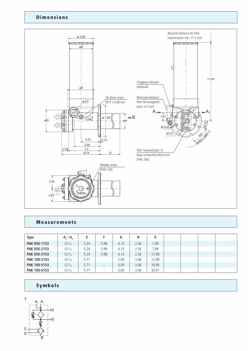
D im ens ions
Measurements
Sy m bo l s
Type A1 / A2 E F G H X
FNK 050-1153 G11/4 5.24 5.98 4.13 2.56 7.99FNK 050-2153 G11/4 5.24 5.98 4.13 2.56 7.99FNK 050-3153 G11/4 5.24 5.98 4.13 2.56 17.99FNK 100-3153 G11/4 5.71 - 5.00 3.46 12.99FNK 100-5153 G11/4 5.71 - 5.00 3.46 18.90FNK 100-6153 G11/4 5.71 - 5.00 3.46 30.91
Required distance for filter maintenance: min. 17.7 inch
Minimum distance from ferromagnetic parts: 0.3 inch
Clogging indicator(optional)
Oil drain screwM12 x 0.06 mm
Bleeder screw(FNK 100)
SMC Screwed joint ½,Hose connection-Ø 0.6 inch(FNK 100)
1
2
3
4
5
Our engineers will be glad to advise you in questions concerning filter application, selection as well as the cleanliness class of the filtered medium attainable under practical operating conditions.
Illustrations may sometimes differ from the original. ARGO-HYTOS is not responsible for any unintentional mistake in this specification sheet.
Subject to change80.30-1us · 0714
Quality management according to DIN EN ISO 9001
To ensure constant quality in production and operation, ARGO-HYTOSfilter elements undergo strict controls and tests according to the following ISO standards:
ISO 2941 Verification of collapse/burst pressure ratingISO 2942 Verification of fabrication integrity (Bubble Point Test)ISO 2943 Verification of material compatibility with fluids
ISO 3968 Evaluation of pressure drop versus flow characteristicsISO 16889 Multi-Pass-Test (evaluation of filter fineness and dirt-holding capacity) ISO 23181 Determination of resistance to flow fatigue using high viscosity fluid
Various quality controls during the production process guarantee the leakfree function and solidity of our filters.
Q u a l i ty Assurance
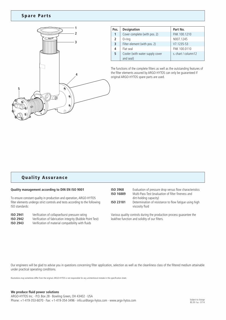
Spare Par t s
Pos. Designation Part No. 1 Cover complete (with pos. 2) FNK 100.1210 2 O-ring N007.1245 3 Filter element (with pos. 2) V7.1235-53 4 Flat seal FNK 100.0110 5 Cooler (with water supply cover s. chart / column12 and seal)
The functions of the complete filters as well as the outstanding features ofthe filter elements assured by ARGO-HYTOS can only be guaranteed if original ARGO-HYTOS spare parts are used.
We produce fluid power solutionsARGO-HYTOS Inc. · P.O. Box 28 · Bowling Green, OH 43402 · USAPhone: +1-419-353-6070 · Fax: +1-419-354-3496 · [email protected] · www.argo-hytos.com