Embed Size (px)
Citation preview
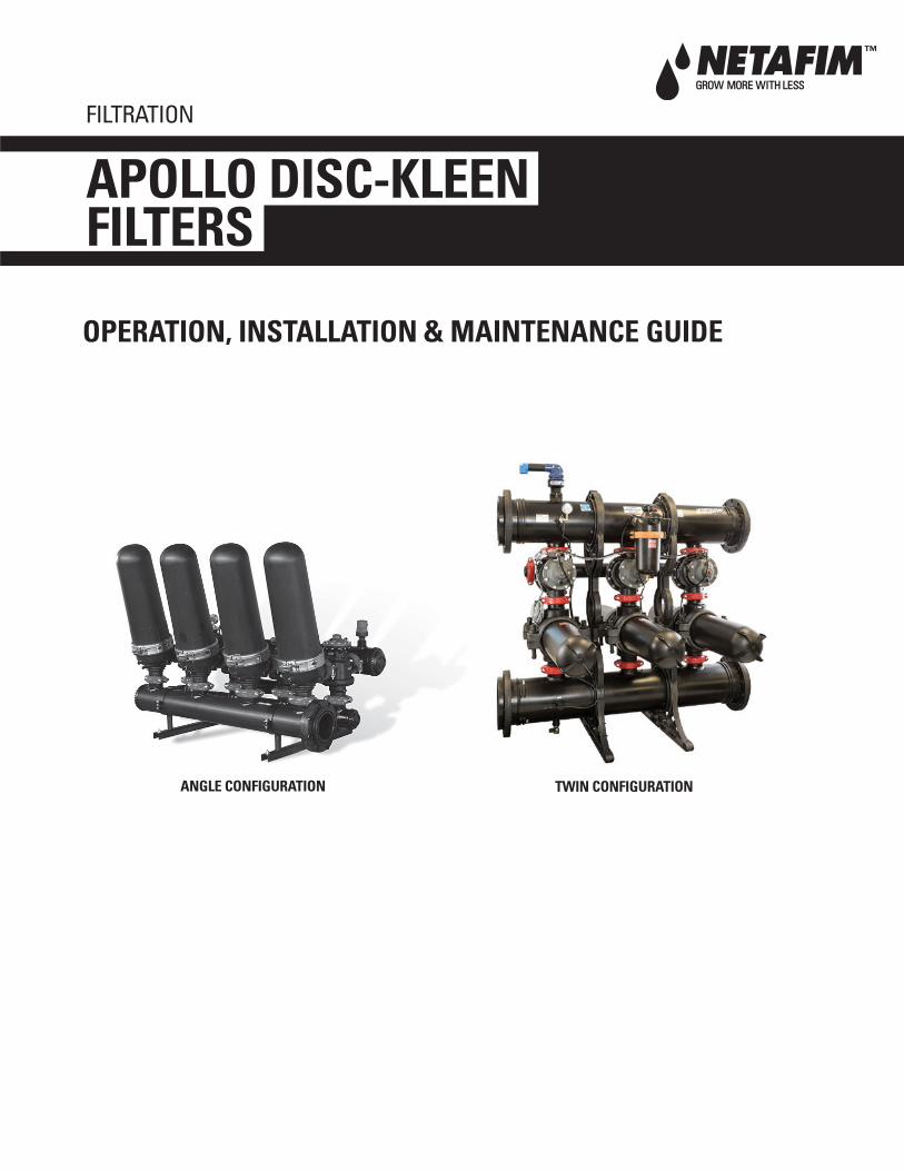
ANGLE CONFIGURATION TWIN CONFIGURATION
OPERATION, INSTALLATION & MAINTENANCE GUIDE
APOLLO DISC-KLEEN FILTERS
FILTRATION
2 • APOLLO DISC-KLEEN FILTER OPERATIONS, MAINTENANCE AND TROUBLESHOOTING GUIDE
TABLE OF CONTENTS
Specifications .................................................................................................................3
Filter Dimensions............................................................................................................4
Water Quality & Maximum Flow Rates ......................................................................5
Filter Operation ...............................................................................................................5
Installation.......................................................................................................................8
Filter Start-up ................................................................................................................10
System Maintenance ..................................................................................................10
Troubleshooting ............................................................................................................13
Replacement Parts ......................................................................................................15
APOLLO DISC-KLEEN FILTER OPERATIONS, MAINTENANCE AND TROUBLESHOOTING GUIDE • 3
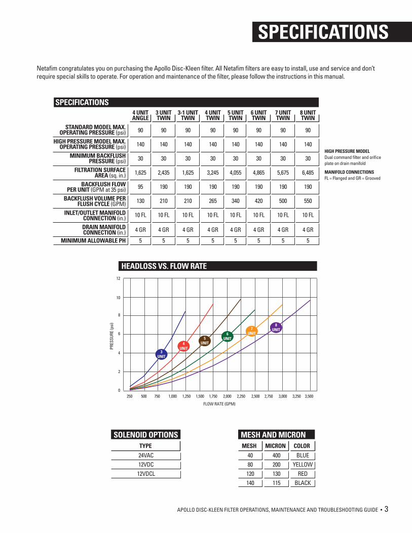
Netafim congratulates you on purchasing the Apollo Disc-Kleen filter. All Netafim filters are easy to install, use and service and don’t require special skills to operate. For operation and maintenance of the filter, please follow the instructions in this manual.
SPECIFICATIONS
STANDARD MODEL MAX.OPERATING PRESSURE (psi)
HIGH PRESSURE MODEL MAX.OPERATING PRESSURE (psi)
MINIMUM BACKFLUSHPRESSURE (psi)
FILTRATION SURFACEAREA (sq. in.)
BACKFLUSH FLOWPER UNIT (GPM at 35 psi)
BACKFLUSH VOLUME PERFLUSH CYCLE (GPM)
INLET/OUTLET MANIFOLDCONNECTION (in.)DRAIN MANIFOLDCONNECTION (in.)
MINIMUM ALLOWABLE PH
4 UNITANGLE
90
140
30
1,625
95
130
10 FL
4 GR
5
4 UNITTWIN
90
140
30
3,245
190
265
10 FL
4 GR
5
SPECIFICATIONS3 UNITTWIN
90
140
30
2,435
190
210
10 FL
4 GR
5
3-1 UNITTWIN
90
140
30
1,625
190
210
10 FL
4 GR
5
5 UNITTWIN
90
140
30
4,055
190
340
10 FL
4 GR
5
8 UNITTWIN
90
140
30
6,485
190
550
10 FL
4 GR
5
6 UNITTWIN
90
140
30
4,865
190
420
10 FL
4 GR
5
7 UNITTWIN
90
140
30
5,675
190
500
10 FL
4 GR
5
HIGH PRESSURE MODELDual command filter and orifice plate on drain manifold
MANIFOLD CONNECTIONSFL = Flanged and GR = Grooved
12
10
8
6
4
2
0
PRES
SURE
(psi
)
FLOW RATE (GPM)
250 500 750 1,000 1,250 1,500 1,750 2,000 2,250 2,500 2,750 3,000 3,250 3,500
3UNIT
4UNIT
5UNIT
6UNIT
7UNIT
8UNIT
HEADLOSS VS. FLOW RATE
SOLENOID OPTIONSTYPE
24VAC12VDC12VDCL
MESH AND MICRONMESH MICRON
400200130115
BLUEYELLOW
REDBLACK
4080120140
COLOR
4 • APOLLO DISC-KLEEN FILTER OPERATIONS, MAINTENANCE AND TROUBLESHOOTING GUIDE
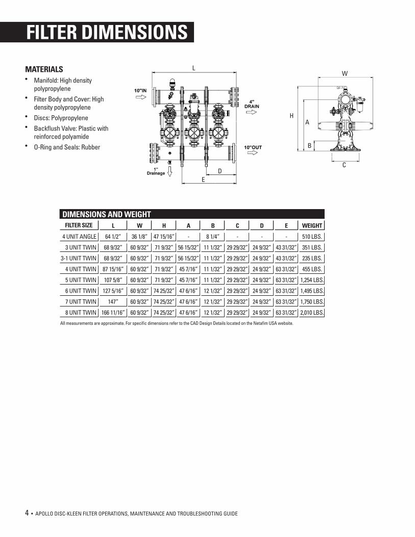
MATERIALS• Manifold: High density
polypropylene• Filter Body and Cover: High
density polypropylene• Discs: Polypropylene• Backflush Valve: Plastic with
reinforced polyamide• O-Ring and Seals: Rubber
FILTER DIMENSIONS
4 UNIT ANGLE
3 UNIT TWIN
3-1 UNIT TWIN
4 UNIT TWIN
5 UNIT TWIN
6 UNIT TWIN
7 UNIT TWIN
8 UNIT TWIN
L
64 1/2”
68 9/32”
68 9/32”
87 15/16”
107 5/8”
127 5/16”
147”
166 11/16”
W
36 1/8”
60 9/32”
60 9/32”
60 9/32”
60 9/32”
60 9/32”
60 9/32”
60 9/32”
H
47 15/16”
71 9/32”
71 9/32”
71 9/32”
71 9/32”
74 25/32”
74 25/32”
74 25/32”
A
-
56 15/32”
56 15/32”
45 7/16”
45 7/16”
47 6/16”
47 6/16”
47 6/16”
B
8 1/4”
11 1/32”
11 1/32”
11 1/32”
11 1/32”
12 1/32”
12 1/32”
12 1/32”
C
-
29 29/32”
29 29/32”
29 29/32”
29 29/32”
29 29/32”
29 29/32”
29 29/32”
D
-
24 9/32”
24 9/32”
24 9/32”
24 9/32”
24 9/32”
24 9/32”
24 9/32”
E
-
43 31/32”
43 31/32”
63 31/32”
63 31/32”
63 31/32”
63 31/32”
63 31/32”
WEIGHT
510 LBS.
351 LBS.
235 LBS.
455 LBS.
1,254 LBS.
1,495 LBS.
1,750 LBS.
2,010 LBS.
DIMENSIONS AND WEIGHTFILTER SIZE
All measurements are approximate. For specific dimensions refer to the CAD Design Details located on the Netafim USA website.
W
HA
B
C
L
DE
APOLLO DISC-KLEEN FILTER OPERATIONS, MAINTENANCE AND TROUBLESHOOTING GUIDE • 5
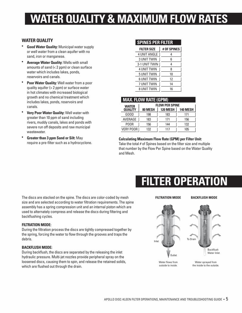
The discs are stacked on the spine. The discs are color-coded by mesh size and are selected according to water filtration requirements. The spine assembly has a spring compression unit and an internal piston which are used to alternately compress and release the discs during filtering and backflushing cycles.
FILTRATION MODE:During the filtration process the discs are tightly compressed together by the spring, forcing the water to flow through the grooves and traps the debris.
BACKFLUSH MODE:During backflush, the discs are separated by the releasing the inlet hydraulic pressure. Multi-jet nozzles provide peripheral spray on the loosened discs, causing them to spin, and release the retained solids, which are flushed out through the drain.
WATER QUALITY• Good Water Quality: Municipal water supply
or well water from a clean aquifer with no sand, iron or manganese.
• Average Water Quality: Wells with small amounts of sand (< 2 ppm) or clean surface water which includes lakes, ponds, reservoirs and canals.
• Poor Water Quality: Well water from a poor quality aquifer (> 2 ppm) or surface water in hot climates with increased biological growth and no chemical treatment which includes lakes, ponds, reservoirs and canals.
• Very Poor Water Quality: Well water with greater than 10 ppm of sand including rivers, muddy canals, lakes and ponds with severe run off deposits and raw municipal wastewater.
• Greater than 3 ppm Sand or Silt: May require a pre-filter such as a hydrocyclone.
BackflushWater Inlet
Water flows fromoutside to inside.
Water sprayed fromthe inside to the outside.
To Drain
FILTRATION MODE BACKFLUSH MODE
Outlet
Inlet
WATER QUALITY & MAXIMUM FLOW RATES
FILTER OPERATION
SPINES PER FILTER FILTER SIZE
4 UNIT ANGLE3 UNIT TWIN
3-1 UNIT TWIN4 UNIT TWIN5 UNIT TWIN6 UNIT TWIN7 UNIT TWIN8 UNIT TWIN
# OF SPINES464810121416
MAX. FLOW RATE (GPM)WATER
QUALITYGOOD
AVERAGEPOOR
VERY POOR
80 MESHFLOW PER SPINE
198183156132
120 MESH183171144117
140 MESH171156132105
Calculating Maximum Flow Rate (GPM) per Filter Unit: Take the total # of Spines based on the filter size and multiple that number by the Flow Per Spine based on the Water Quality and Mesh.
6 • APOLLO DISC-KLEEN FILTER OPERATIONS, MAINTENANCE AND TROUBLESHOOTING GUIDE
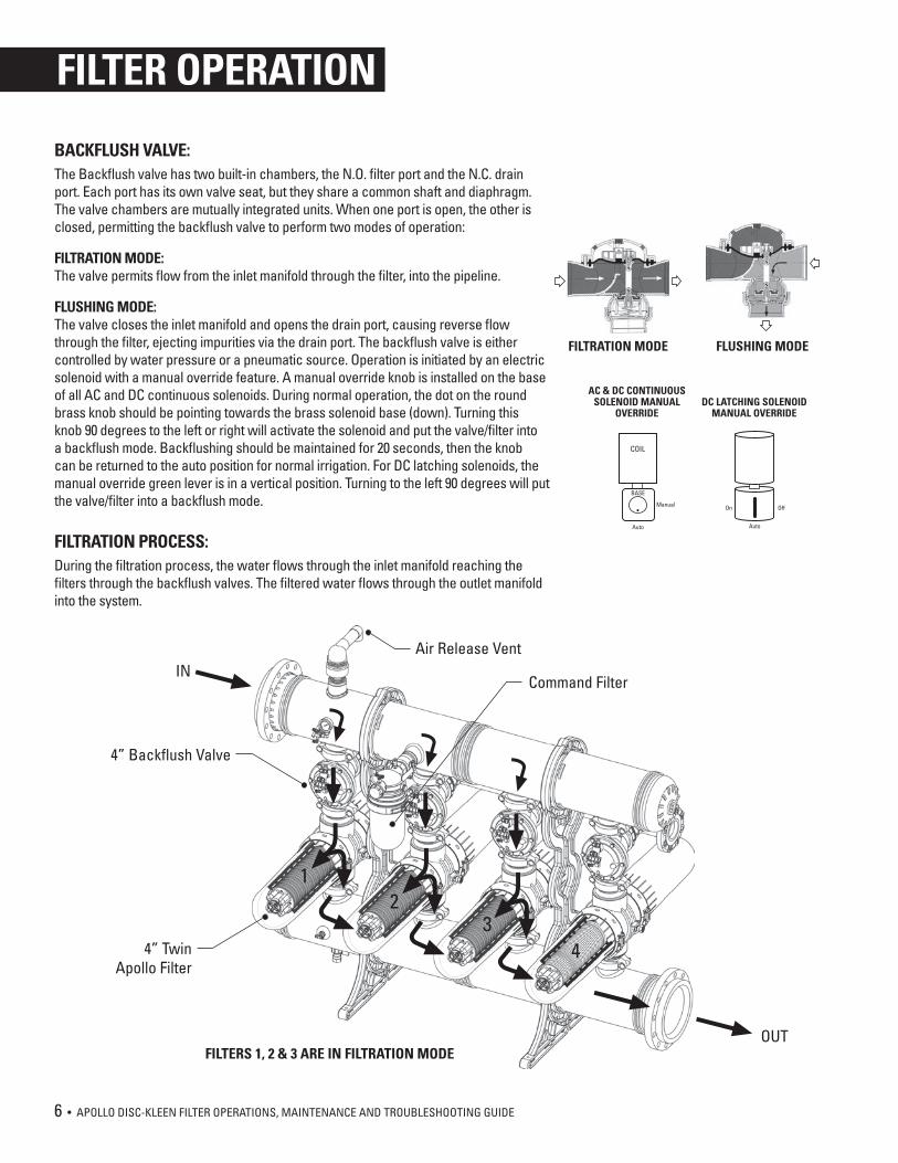
BACKFLUSH VALVE:The Backflush valve has two built-in chambers, the N.O. filter port and the N.C. drain port. Each port has its own valve seat, but they share a common shaft and diaphragm. The valve chambers are mutually integrated units. When one port is open, the other is closed, permitting the backflush valve to perform two modes of operation:
FILTRATION MODE:The valve permits flow from the inlet manifold through the filter, into the pipeline.
FLUSHING MODE:The valve closes the inlet manifold and opens the drain port, causing reverse flow through the filter, ejecting impurities via the drain port. The backflush valve is either controlled by water pressure or a pneumatic source. Operation is initiated by an electric solenoid with a manual override feature. A manual override knob is installed on the base of all AC and DC continuous solenoids. During normal operation, the dot on the round brass knob should be pointing towards the brass solenoid base (down). Turning this knob 90 degrees to the left or right will activate the solenoid and put the valve/filter into a backflush mode. Backflushing should be maintained for 20 seconds, then the knob can be returned to the auto position for normal irrigation. For DC latching solenoids, the manual override green lever is in a vertical position. Turning to the left 90 degrees will put the valve/filter into a backflush mode.
FILTRATION PROCESS:During the filtration process, the water flows through the inlet manifold reaching the filters through the backflush valves. The filtered water flows through the outlet manifold into the system.
Auto
COIL
OffOn
Auto
BASE
Manual
AC & DC CONTINUOUSSOLENOID MANUAL
OVERRIDEDC LATCHING SOLENOID
MANUAL OVERRIDE
Command Filter
4” Backflush Valve
4” TwinApollo Filter
IN
OUT
34
21
FILTERS 1, 2 & 3 ARE IN FILTRATION MODE
Air Release Vent
FILTER OPERATION
FLUSHING MODEFILTRATION MODE
APOLLO DISC-KLEEN FILTER OPERATIONS, MAINTENANCE AND TROUBLESHOOTING GUIDE • 7
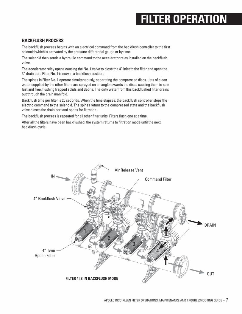
BACKFLUSH PROCESS:The backflush process begins with an electrical command from the backflush controller to the first solenoid which is activated by the pressure differential gauge or by time.
The solenoid then sends a hydraulic command to the accelerator relay installed on the backflush valve.
The accelerator relay opens causing the No. 1 valve to close the 4” inlet to the filter and open the 3” drain port. Filter No. 1 is now in a backflush position.
The spines in Filter No. 1 operate simultaneously, separating the compressed discs. Jets of clean water supplied by the other filters are sprayed on an angle towards the discs causing them to spin fast and free, flushing trapped solids and debris. The dirty water from this backflushed filter drains out through the drain manifold.
Backflush time per filter is 20 seconds. When the time elapses, the backflush controller stops the electric command to the solenoid. The spines return to the compressed state and the backflush valve closes the drain port and opens for filtration.
The backflush process is repeated for all other filter units. Filters flush one at a time.
After all the filters have been backflushed, the system returns to filtration mode until the next backflush cycle.
Air Release Vent
Command Filter
4” Backflush Valve
4” TwinApollo Filter
IN
OUT
DRAIN
34
21
FILTER 4 IS IN BACKFLUSH MODE
FILTER OPERATION
8 • APOLLO DISC-KLEEN FILTER OPERATIONS, MAINTENANCE AND TROUBLESHOOTING GUIDE
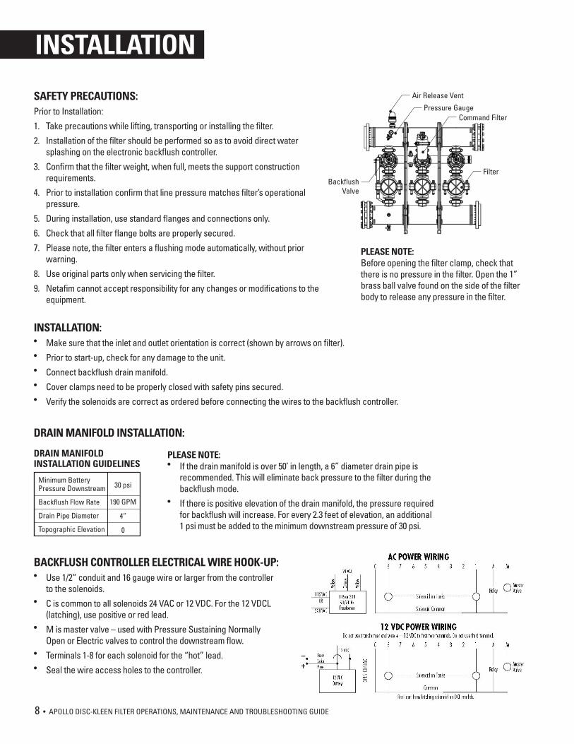
Air Release Vent
FilterBackflush
Valve
Pressure GaugeCommand Filter
PLEASE NOTE:• If the drain manifold is over 50’ in length, a 6” diameter drain pipe is
recommended. This will eliminate back pressure to the filter during the backflush mode.
• If there is positive elevation of the drain manifold, the pressure required for backflush will increase. For every 2.3 feet of elevation, an additional 1 psi must be added to the minimum downstream pressure of 30 psi.
INSTALLATION:• Make sure that the inlet and outlet orientation is correct (shown by arrows on filter).• Prior to start-up, check for any damage to the unit.• Connect backflush drain manifold.• Cover clamps need to be properly closed with safety pins secured.• Verify the solenoids are correct as ordered before connecting the wires to the backflush controller.
DRAIN MANIFOLD INSTALLATION:
BACKFLUSH CONTROLLER ELECTRICAL WIRE HOOK-UP:• Use 1/2” conduit and 16 gauge wire or larger from the controller
to the solenoids.• C is common to all solenoids 24 VAC or 12 VDC. For the 12 VDCL
(latching), use positive or red lead.• M is master valve – used with Pressure Sustaining Normally
Open or Electric valves to control the downstream flow.• Terminals 1-8 for each solenoid for the “hot” lead.• Seal the wire access holes to the controller.
SAFETY PRECAUTIONS:Prior to Installation:
1. Take precautions while lifting, transporting or installing the filter.
2. Installation of the filter should be performed so as to avoid direct water splashing on the electronic backflush controller.
3. Confirm that the filter weight, when full, meets the support construction requirements.
4. Prior to installation confirm that line pressure matches filter’s operational pressure.
5. During installation, use standard flanges and connections only.
6. Check that all filter flange bolts are properly secured.
7. Please note, the filter enters a flushing mode automatically, without prior warning.
8. Use original parts only when servicing the filter.
9. Netafim cannot accept responsibility for any changes or modifications to the equipment.
PLEASE NOTE:Before opening the filter clamp, check that there is no pressure in the filter. Open the 1” brass ball valve found on the side of the filter body to release any pressure in the filter.
INSTALLATION
DRAIN MANIFOLDINSTALLATION GUIDELINES
Minimum BatteryPressure Downstream
Backflush Flow Rate
Drain Pipe Diameter
Topographic Elevation
30 psi
190 GPM
4”
0
APOLLO DISC-KLEEN FILTER OPERATIONS, MAINTENANCE AND TROUBLESHOOTING GUIDE • 9
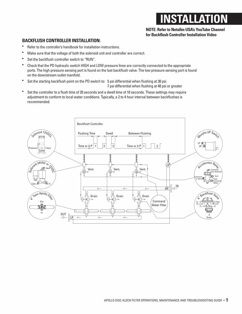
BACKFLUSH CONTROLLER INSTALLATION:• Refer to the controller’s handbook for installation instructions.• Make sure that the voltage of both the solenoid unit and controller are correct.• Set the backflush controller switch to “RUN”.• Check that the PD hydraulic switch HIGH and LOW pressure lines are correctly connected to the appropriate
ports. The high pressure sensing port is found on the last backflush valve. The low pressure sensing port is found on the downstream outlet manifold.
• Set the starting backflush point on the PD switch to: 5 psi differential when flushing at 30 psi 7 psi differential when flushing at 40 psi or greater
• Set the controller to a flush time of 20 seconds and a dwell time of 10 seconds. These settings may require adjustment to conform to local water conditions. Typically, a 2 to 4 hour interval between backflushes is recommended.
Backflush Controller
Flushing Time Between FlushingDwell
Vent. Vent. Vent.
1 2 3Time or ∆ P 1 2Time or ∆ P
Drain Drain Drain
CommandWater Filter
HPIN
LPOUT
Solenoid 12VDCL
InCom.
Solen
oid 24VAC or 12VDC
Vent
In
Out
4” Tw
in Apollo Filter
LPHP
M
urphy ∆P Switch
VentFeedCommandWater
Commandto Valve
Accelerator Relay
Commandfrom Solenoid
In Out4”
Backflush Valve
Drain
PressureComm
Vent
INSTALLATIONNOTE: Refer to Netafim USA’s YouTube Channel for Backflush Controller Installation Video
10 • APOLLO DISC-KLEEN FILTER OPERATIONS, MAINTENANCE AND TROUBLESHOOTING GUIDE
GENERAL REQUIREMENTS AND MAINTENANCE:• Confirm there is 30 psi of pressure downstream of the filter during backflush.• Check that the Pressure Differential (PD) Gauge returns to 0-2 psi after a
backflush.• All vent tubes need to vent freely to atmosphere without any back pressure.• To minimize damage to the backflush controller, always keep the door closed
and turn off the power when not using the controller for long periods of time.
SEASONAL MAINTENANCE:• At the end of the irrigation season, just before shutdown, initiate a backflush
with the required pressure and turn off the water. This will ensure the discs remain clean during the offseason.
• Manually clean the discs if needed – see detailed instructions on Page 11.• In order to prevent the filter from becoming damaged under freezing
conditions, drain all the water from the filter and leave the drain valve open. Disconnect the hydraulic tubes from the PD Gauge.
START-UP OPERATION:• Flush out the main line upstream of the filter by opening
the blind flange connection of the inlet manifold. After initial flushing, reassemble the blind flange.
• Turn the system on slowly to build up the pressure.• Start the backflush cycle making sure that all system
components function correctly.• Check that the PD gauge reads zero after a backflush
cycle.
IF FILTER LOADS UP DURING START-UP:• Close the downstream (flow control) valve to increase
pressure downstream of the filter.• Initiate backflush cycle until the discs are clean.• Slowly reopen the downstream valve.• If the pressure difference remains high, check and see if
the flow rate is too high. An excessive flow rate through the filter causes excessive pressure loss.
FILTER START-UP
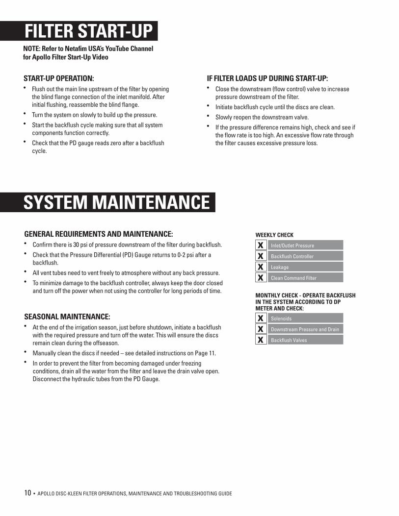
SYSTEM MAINTENANCEWEEKLY CHECK
Inlet/Outlet PressurexBackflush ControllerxLeakagexClean Command Filterx
SolenoidsxDownstream Pressure and DrainxBackflush Valvesx
MONTHLY CHECK - OPERATE BACKFLUSH IN THE SYSTEM ACCORDING TO DP METER AND CHECK:
NOTE: Refer to Netafim USA’s YouTube Channel for Apollo Filter Start-Up Video
APOLLO DISC-KLEEN FILTER OPERATIONS, MAINTENANCE AND TROUBLESHOOTING GUIDE • 11
PLEASE NOTE:• Make sure the system is not under
pressure.• Before removing the cover you
may experience the vacuum phenomenon which will make removing the cover very difficult or almost impossible.
• DO NOT insert any sharp tools or objects in between the cover and the body. You may damage the hydraulic seal and the cover.
• In order to remove the cover easily, you should drain the water from the filter.
• You may drain the filter through the drain valve located on the filter body. Once the filter is empty, the cover can then be removed safely and easily.
DISC CLEANING INSTRUCTIONS:• Use the clamp wrench to loosen the bolts. • Slide the clamp down and off the filter.• Remove the filter cover from the filter body.• Unscrew the butterfly nut on the filtration element.• Remove the tightening cylinders.• Remove the discs. For convenience, we recommend using a plastic bag.• Tie each disc set on a string and place them in a cleaning solution. Refer to
instructions on page 12 for recommended cleaning solutions based on water deposits.
• Thoroughly wash the discs with fresh water and then reassemble the discs on the spine.
• Check that the correct quantity of discs is assembled on the spine. When the discs are pressed with two hands, the top disc should be level with the imprinted white line on the outside of the spine.
• Replace the tightening cylinder and tighten the butterfly nut until it stops - do not overtighten.
• Ensure the cover O-ring is in the correct position with the holes facing out.• Place the filter cover on the filter body and secure it with a slight clockwise
rotation. Reposition the clamp onto the cover and tighten the bolts with the clamp wrench.
SYSTEM MAINTENANCENOTE: Refer to Netafim USA’s YouTube Channel for Apollo Disc Cleaning Video
12 • APOLLO DISC-KLEEN FILTER OPERATIONS, MAINTENANCE AND TROUBLESHOOTING GUIDE
DISC CLEANING INSTRUCTIONS FOR WELL WATER WITH MANGANESE, IRON OR CARBONATE DEPOSITS:
STEP 1• Make a 10% Hydrochloric Acid solution. Pour 1.8 gallons
of water into a container and add .80 gallons Hydrochloric Acid (30-35%) to the water.
• Soak the discs in this solution making sure the discs are loose and have good contact on both sides with the acid solution. Do not put too many discs in at one time.
• Stir the discs in the solution a few times.• Total soaking time is 1 to 3 hours. If the solution is no longer
cleaning the discs, replace it with a new mixture.• Remove the discs and rinse well with water – there should
only be a pale sedimentation on the discs.
STEP 2• After the discs have been rinsed with water, they must be
soaked in a 10% Peroxide solution to remove the organic residue.
• Make a 10% Peroxide solution. Pour 1.8 gallons of water into a container and add .80 gallons of Hydrogen Peroxide (35%) or pour 2.1 gallons of water into the container and add .53 gallons of Hydrogen Peroxide (50%) to the water.
• Soak the discs in this solution making sure the discs are loose and have good contact on both sides with the Peroxide solution. Do not put too many discs in at one time.
• Stir the discs in the solution a few times.• Total soaking time is 1 to 3 hours. If the solution is no longer
cleaning the discs, replace it with a new mixture.• Remove the discs and rinse well with water – there should
no longer be any residue between the grooves of the discs.• Put the discs on the spine and spine assembly in the filter
bank.• Flush the filter bank a few times to remove all chemicals.
DISC CLEANING INSTRUCTIONS FOR SURFACE WATER WITH ORGANIC AND BIOLOGICAL RESIDUE:
STEP 1• Make a 10% Peroxide solution. Pour 1.8 gallons of water into a
container and add .80 gallons of Hydrogen Peroxide (35%) or pour 2.1 gallons of water into the container and add .53 gallons of Hydrogen Peroxide (50%) to the water.
• Soak the discs in this solution making sure the discs are loose and have good contact on both sides with the Peroxide solution. Do not put too many discs in at one time.
• Stir the discs in the solution a few times.• Total soaking time is 1 to 3 hours. If the solution is no longer
cleaning the discs, replace it with a new mixture.• Remove the discs and rinse well with water – there should
only be a pale sedimentation on the discs.
STEP 2• After the discs have been rinsed with water, they must be
soaked in a 10% Hydrochloric Acid solution to remove the organic residue.
• Make a 10% Hydrochloric Acid solution. Pour 1.8 gallons of water into a container and add .80 gallons Hydrochloric Acid (30-35%) to the water.
• Soak the discs in this solution making sure the discs are loose and have good contact on both sides with the acid solution. Do not put too many discs in at one time.
• Stir the discs in the solution a few times.• Total soaking time is 1 to 3 hours. If the solution is no longer
cleaning the discs, replace it with a new mixture.• Remove the discs and rinse well with water – there should no
longer be any residue between the grooves of the discs.• Put the discs on the spine and spine assembly in the filter
bank.• Flush the filter bank a few times to remove all chemicals.
CAUTION: When blowing out with compressed air, make sure all parts are opened.
SYSTEM MAINTENANCENOTE: Refer to Netafim USA’s YouTube Channel for Apollo Disc Cleaning Video
APOLLO DISC-KLEEN FILTER OPERATIONS, MAINTENANCE AND TROUBLESHOOTING GUIDE • 13
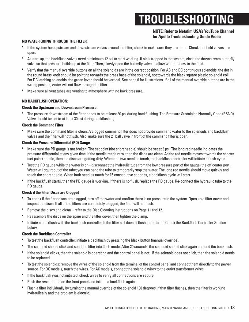
NO WATER GOING THROUGH THE FILTER:• If the system has upstream and downstream valves around the filter, check to make sure they are open. Check that field valves are
open.• At start-up, the backflush valves need a minimum 12 psi to start working. If air is trapped in the system, close the downstream butterfly
valve so that pressure builds up at the filter. Then, slowly open the butterfly valve to allow water to flow to the field.• Verify that the manual override buttons on all the solenoids are in the correct position. For AC and DC continuous solenoids, the dot in
the round brass knob should be pointing towards the brass base of the solenoid, not towards the black square plastic solenoid coil. For DC latching solenoids, the green lever should be vertical. See page 6 for illustrations. If all of the manual override buttons are in the wrong position, water will not flow through the filter.
• Make sure all vent tubes are venting to atmosphere with no back pressure.
NO BACKFLUSH OPERATION:
Check the Upstream and Downstream Pressure• The pressure downstream of the filter needs to be at least 30 psi during backflushing. The Pressure Sustaining Normally Open (PSNO)
Valve should be set to at least 30 psi during backflushing.
Check the Command Filter• Make sure the command filter is clean. A clogged command filter does not provide command water to the solenoids and backflush
valves and the filter will not flush. Also, make sure the 2” ball valve in front of the command filter is open.
Check the Pressure Differential (PD) Gauge• Make sure the PD gauge is not broken. The set point (the short needle) should be set at 5 psi. The long red needle indicates the
pressure differential at any given time. If the needle reads zero, then the discs are clean. As the red needle moves towards the shorter (set point) needle, then the discs are getting dirty. When the two needles touch, the backflush controller will initiate a flush cycle.
• Test the PD gauge while the water is on - disconnect the hydraulic tube from the low pressure port of the gauge (the off center port). Water will squirt out of the tube; you can bend the tube to temporarily stop the water. The long red needle should move quickly and touch the short needle. When both needles touch for 15 consecutive seconds, a backflush cycle will start.
• If the backflush starts, then the PD gauge is working. If there is no flush, replace the PD gauge. Re-connect the hydraulic tube to the PD gauge.
Check if the Filter Discs are Clogged • To check if the filter discs are clogged, turn off the water and confirm there is no pressure in the system. Open up a filter cover and
inspect the discs. If all of the filters are completely clogged, the filter will not flush. • Remove the discs and clean – refer to the Disc Cleaning Instructions on Page 11 and 12. • Reassemble the discs on the spine and the filter cover, then tighten the clamp. • Initiate a backflush with the backflush controller. If the filter still doesn’t flush, refer to the Check the Backflush Controller Section
below.
Check the Backflush Controller• To test the backflush controller, initiate a backflush by pressing the black button (manual override). • The solenoid should click and send the filter into flush mode. After 20 seconds, the solenoid should click again and end the backflush.• If the solenoid clicks, then the solenoid is operating and the control panel is not. If the solenoid does not click, then the solenoid needs
to be replaced• To test the solenoids: remove the wires of the solenoid from the terminal of the control panel and connect them directly to the power
source. For DC models, touch the wires. For AC models, connect the solenoid wires to the outlet transformer wires.• If the backflush was not initiated, check wires to verify all connections are secure. • Push the reset button on the front panel and initiate a backflush again.• Flush a filter individually by turning the manual override of the solenoid 180 degrees. If that filter flushes, then the filter is working
hydraulically and the problem is electric.
TROUBLESHOOTINGNOTE: Refer to Netafim USA’s YouTube Channel for Apollo Troubleshooting Guide Video
14 • APOLLO DISC-KLEEN FILTER OPERATIONS, MAINTENANCE AND TROUBLESHOOTING GUIDE
• For AC backflush controllers, make sure the transformer is still functioning and replace if needed. • The controller panel can malfunction if exposed to moist or dusty conditions, rust, or lightning. If you suspect
any of these causes, contact the backflush controller manufacturer for inspection and possible warranty or repair. Or call Netafim USA Technical Support for assistance.
CONTINUOUS BACKFLUSHING: Constant Water Flowing Out of the Drain Manifold• If there is constant water going through the drain manifold, then one of the backflush valves is stuck in the flush
position. This can be caused by one of these three issues:
- There may be debris stuck in the drain port of the backflush valve which does not allow the valve to return to the filtration position. Determine which valve is flushing all of the time. Turn the manual override of the solenoid to flush and then return the knob to filtration. Make sure the knob is in exactly the correct position. If the valve is still flushing, turn off the water.
- Remove the entire 4” drain manifold from the back of the backflush valves. Visually inspect the back side of all valves to see if there is debris. Start to disassemble the backflush valve from the back by removing the large plastic union. Put the large spring or large o-ring in a secure place. Remove the small bolt from the stem, pull out the black round piece and remove any debris. Carefully reassemble the valve and attach the drain manifold.
- The solenoid may be stuck and not returning to filtration mode. On the Backflush Controller, switch the terminal wire (the wire connected to terminal 1 and 2 for example) from a stuck solenoid to a working solenoid. If the problem moves with the solenoid that is stuck, then the problem is in the solenoid. Disassemble the solenoid to clean any debris. If the problem persists, replace the solenoid coil with a new one.
- The diaphragm of the backflush valve may be torn. To confirm, close the ball valve in front of the 2” command filter. If water is still flushing from the drain manifold, the diaphragm may be torn. Turn off the water and remove all of the bolts from the bonnet of the valve. Remove the diaphragm and inspect for tear. Replace if necessary.
Filter Completes a Backflush Cycle, Stops and Backflushes Again:• If the filter is constantly backflushing by going through a cycle, stopping for 1 minute and backflushing again,
look at the controller to see if the word “Alarm” is flashing. If it is, then the filter is probably clogged. • The filter will get clogged for the following reasons:
- There was less than 30 psi on the downstream side of the filter during backflush.
- The water quality changed and became too dirty for the filter to keep up. (Check for severe algae bloom or high silt load).
- The flow rate was increased by turning on an additional valve, so the filter cannot keep up with the increased flow rate.
- The diameter of the drain pipe is too long or too small or it’s plumbed so that it elevates back into a reservoir. All of these will create back pressure on the filter during the flush cycle and have a negative effect on the quality of the flush. The drain pipe should be at least 4” diameter, not to exceed 50 feet long and free flow to a drain pit. If the drain pipe needs to be longer than 50 feet, use a 6” pipe. There should not be a check valve or gate valve on the drain pipe.
- Remove the discs from the spines and clean them manually. Refer to the Disc Cleaning Instructions on Pages 11 and 12.
CHECK THE BACKFLUSH CONTROLLER (CON’T)
TROUBLESHOOTINGNOTE: Refer to Netafim USA’s YouTube Channel for Apollo Troubleshooting Guide Video
APOLLO DISC-KLEEN FILTER OPERATIONS, MAINTENANCE AND TROUBLESHOOTING GUIDE • 15
REPLACEMENT PARTS
NOTE: Substitute *** with desired mesh.
2425 23
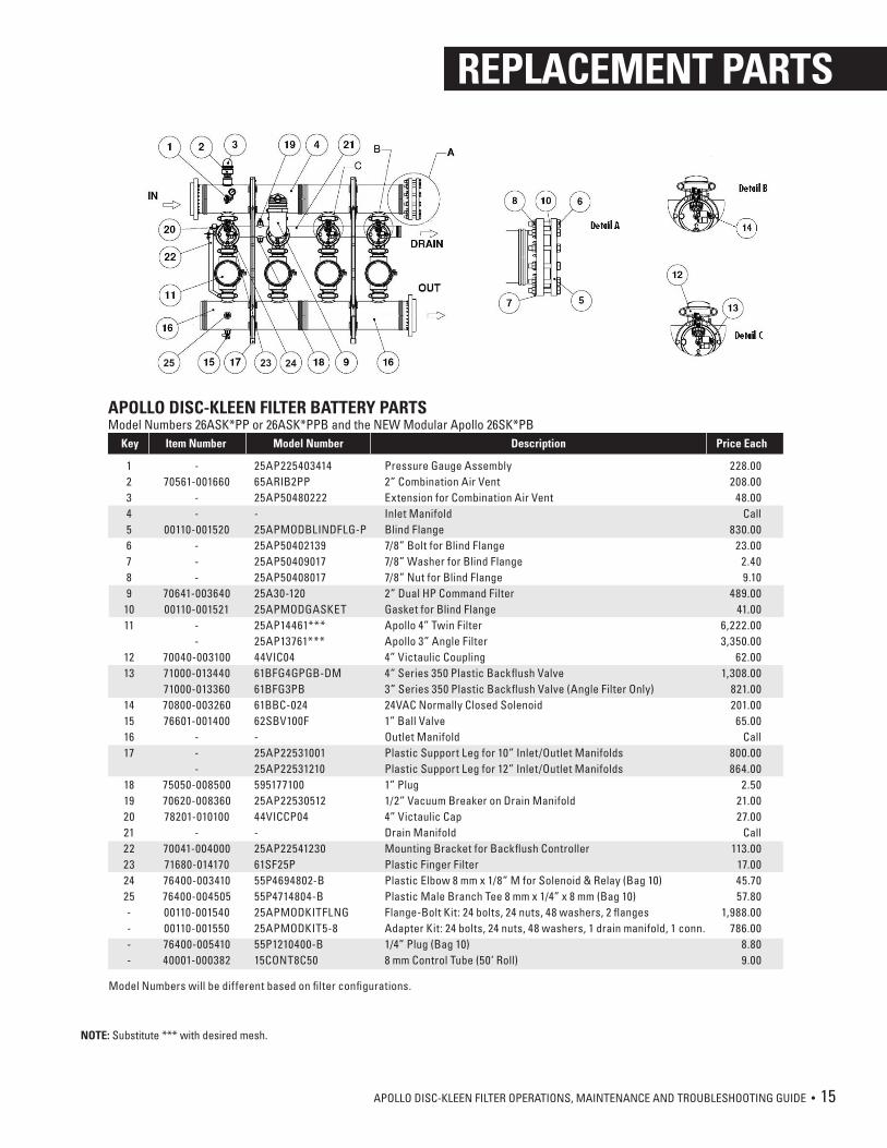
Pressure Gauge Assembly2” Combination Air VentExtension for Combination Air VentInlet ManifoldBlind Flange7/8” Bolt for Blind Flange7/8” Washer for Blind Flange7/8” Nut for Blind Flange2” Dual HP Command FilterGasket for Blind FlangeApollo 4” Twin FilterApollo 3” Angle Filter4” Victaulic Coupling4“ Series 350 Plastic Backflush Valve3” Series 350 Plastic Backflush Valve (Angle Filter Only)24VAC Normally Closed Solenoid1” Ball ValveOutlet ManifoldPlastic Support Leg for 10” Inlet/Outlet ManifoldsPlastic Support Leg for 12” Inlet/Outlet Manifolds1” Plug 1/2” Vacuum Breaker on Drain Manifold4” Victaulic CapDrain ManifoldMounting Bracket for Backflush ControllerPlastic Finger FilterPlastic Elbow 8 mm x 1/8” M for Solenoid & Relay (Bag 10)Plastic Male Branch Tee 8 mm x 1/4” x 8 mm (Bag 10)Flange-Bolt Kit: 24 bolts, 24 nuts, 48 washers, 2 flangesAdapter Kit: 24 bolts, 24 nuts, 48 washers, 1 drain manifold, 1 conn.1/4” Plug (Bag 10)8 mm Control Tube (50’ Roll)
Item Number Model Number Description Price EachKey
228.00208.00
48.00Call
830.0023.00
2.409.10
489.0041.00
6,222.003,350.00
62.001,308.00
821.00201.0065.00
Call800.00864.00
2.5021.0027.00
Call113.00
17.0045.7057.80
1,988.00786.00
8.809.00
123456789
1011
1213
14151617
1819202122232425----
-70561-001660
--
00110-001520---
70641-00364000110-001521
--
70040-00310071000-01344071000-01336070800-00326076601-001400
---
75050-00850070620-00836078201-010100
-70041-00400071680-01417076400-00341076400-00450500110-00154000110-00155076400-00541040001-000382
25AP22540341465ARIB2PP25AP50480222-25APMODBLINDFLG-P25AP5040213925AP5040901725AP5040801725A30-12025APMODGASKET25AP14461***25AP13761***44VIC0461BFG4GPGB-DM61BFG3PB61BBC-02462SBV100F-25AP2253100125AP2253121059517710025AP2253051244VICCP04-25AP2254123061SF25P55P4694802-B55P4714804-B25APMODKITFLNG25APMODKIT5-855P1210400-B15CONT8C50
APOLLO DISC-KLEEN FILTER BATTERY PARTS Model Numbers 26ASK*PP or 26ASK*PPB and the NEW Modular Apollo 26SK*PB
Model Numbers will be different based on filter configurations.
REPLACEMENT PARTS
NETAFIM USA5470 E. Home Ave.Fresno, CA 93727CS 888 638 2346www.netafimusa.com
APOPS 10/17
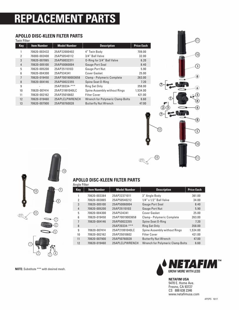
NOTE: Substitute *** with desired mesh.
3” Angle Body1/4” x 1/2” Ball ValveGauge Port SealGauge Port NutCover GasketClamp - Polymeric CompleteSpine Seat O-RingRing Set OnlySpine Assembly without RingsFilter CoverButterfly Nut WrenchWrench for Polymeric Clamp Bolts
Item Number Model Number Description Price EachKey
361.0034.00
8.405.90
25.00263.00
7.20358.00
1,534.00421.00
47.006.60
123456789
101112
70620-00338470620-00386570620-00510070620-00520070620-00430070620-01945070620-004146
-70620-00741470620-00216270620-00790070620-019460
25AP2237101125AP5054021225AP5006000425AP2511010325AP53434125AP7001900365825AP5002235525AP20334-***25AP21991040LC25AP2501060225AP5076002825APLCLPWRENCH
APOLLO DISC-KLEEN FILTER PARTS Angle Filter
4” Twin Body3/4” Ball ValveO-Ring for 3/4” Ball ValveGauge Port SealGauge Port NutCover GasketClamp - Polymeric CompleteSpine Seat O-RingRing Set OnlySpine Assembly without RingsFilter CoverWrench for Polymeric Clamp BoltsButterfly Nut Wrench
Item Number Model Number Description Price EachKey
709.0032.00
6.208.405.90
25.00263.00
7.20358.00
1,534.00421.00
6.6047.00
123456789
10111213
70620-00343276000-00240070620-00706570620-00510070620-00520070620-00430070620-01945070620-004146
-70620-00741470620-00216270620-01946070620-007900
25AP2200040225AP5054011225AP5003231125AP5006000425AP2511010325AP53434125AP70019000365825AP5002235525AP20334-***25AP21991040LC25AP2501060225APLCLPWRENCH25AP50760028
APOLLO DISC-KLEEN FILTER PARTS Twin Filter 11
9
10
11
10
912
13
11
12