Embed Size (px)
Citation preview
BOND BEHAVIOR OF CFRP STRENGTHENED STEEL STRUCTURES
D. Schnerch 1, M. Dawood 2, S. Rizkalla 2, E. Sumner 2 and K. Stanford 3 ABSTRACT
Recent research has focused on rehabilitation and strengthening of steel structures and bridges using
fiber reinforced polymer (FRP) materials. The bond behavior of FRP materials to steel structures is
quite different from that of concrete structures. Preliminary test results showed the occurrence of very
high bond stresses for most strengthening applications due to the amount of strengthening required for
steel structures and bridges. In this paper, surface preparation methods and means of preventing
galvanic corrosion are discussed. The results of an experimental program for selection of suitable
adhesives through determination of the development length is discussed as well as preliminary testing
showing the importance of proper detailing of the ends of the FRP strips. The shear stress distribution
determined in the experimental program is compared to analytical models using a stress-based
approach. The remainder of the paper focuses on the current methods for determining bond stresses
and their use for the design of FRP strengthening system for steel structures.
KEYWORDS
High modulus CFRP, steel bridge, strengthening, rehabilitation, bond stresses
_______________________
1 Wiss, Janney, Elstner Associates, Inc. 245 First Street, Suite 1200, Cambridge, Massachusetts, USA. E-mail: [email protected], tel: 1.617.225.9080, fax: 1.617.225.9081 2 Department Civil, Construction, And Environmental Engineering, North Carolina State University 3 Sutton-Kennerly and Associates, Greensboro, North Carolina, USA
Schnerch et al. (2006) p. 2 of 29
1.0 INTRODUCTION
Innovative methods are required for the strengthening and rehabilitation of steel structures that are
deficient due to the demand to increase the specified load and/or deterioration as a result of corrosion.
A considerable body of research has established the successful use of carbon fiber reinforced polymer
(CFRP) materials for strengthening concrete structures. With the introduction of new high modulus
CFRP materials, the possibility for providing a solution to the ongoing problem of infrastructure
deterioration may be extended to steel structures as well. Bond stresses may be much more critical
for steel structures than for concrete structures since more strengthening material is needed for steel
structures to achieve a similar increase in strength due to the inherent high strength of steel and also
since the debonding failure does not occur in the substrate as in concrete structures. Further
complications may arise due to the potential for galvanic corrosion between the carbon and steel
materials. Despite these challenges, since many structures built in the post-World War II era are
already past their design life, the inventory of deteriorated steel structures and bridges in need of
rehabilitation are extremely significant (Tang and Hooks, 2001). The aim of this paper is to examine
the proper techniques for the bond of CFRP to steel structures and compare the results of the
experimental program to analytical methods of determining bond stresses. The determination of these
bond stresses is necessary for the design of the CFRP strengthening for steel structures.
2.0 BONDING OF HIGH MODULUS CFRP STRIPS TO STEEL STRUCTURES
Proper installation of high modulus CFRP strips is essential in ensuring both the long-term
performance of the system and that the behavior of the system matches the intentions of the designer.
A certain level of care and expertise is required to ensure that these goals are met. Research into the
nature of bonding between FRP materials and metallic structures was first investigated by the
aerospace and naval industries. Later adoption of the technique for civil engineering applications has
typically used CFRP instead of GFRP due to the more reasonable necessary thickness of the applied
strengthening material. The axial stiffness required for strengthening steel structures is much higher
Schnerch et al. (2006) p. 3 of 29
than for concrete or masonry structures that have limited tensile strength, justifying the use of much
higher modulus strengthening materials.
2.1 Surface Preparation
Bonded joints are often the most effective way to join two different adherends, since the resulting
stress concentrations at the joint are much lower than for bolted connections. Furthermore, the
anisotropic nature of most CFRP materials would preclude bolting as a connection method. To ensure
full utilization of the applied CFRP material, surface preparation of the steel must be undertaken to
enhance the formation of chemical bonds between the adherend and the adhesive. This requires a
chemically active surface that is free from contaminants. Most surface treatment involves cleaning,
followed by removal of weak layers and then re-cleaning (Mays and Hutchinson, 1992). Degreasing
is a necessary first step in preparing most metals to remove, oils and other potential contaminates.
Brushing, ultrasonic or vapor degreasing systems are claimed to be most efficient in removing this
surface contamination, especially when sufficient amounts of solvent are used (Hashim, 1999).
Contamination may then be removed with the excess solvent, rather than simply redeposited on the
surface as the solvent evaporates.
The most effective means of achieving a high-energy steel surface is by grit blasting (Sykes, 1982,
Hutchinson, 1987, and Hollaway and Cadei, 2002). Parker (1994) found that for composite joints,
those that were grit blasted had higher peel strengths than those that were hand abraded. Grits are
found to have a clean cutting action that can expose a clean surface, unlike wire brushing. Grit
blasting procedures using angular grit, removes the inactive oxide and hydroxide layers by cutting and
deformation of the base material. The size of the grit will also affect the surface profile of the steel.
Harris and Beevers (1999) confirmed that finer grit particles produced smoother surfaces than coarser
particles in an investigation using three-dimensional profilometry measurements. For two of the three
grits studied, smoother surfaces exhibited higher surface energy readings as determined from static
Schnerch et al. (2006) p. 4 of 29
contact angle measurements. However, the initial joint strengths were independent of the coarseness
of the grit. Furthermore, the long-term durability was not affected by the surface profile.
Following grit blasting, the surface may be contaminated with fine abrasive dust. It has is generally
been agreed that abrasive dust should be removed prior to bonding. Hollaway and Cadei (2002) state
that the dust should be removed by dry wipe, or by a vacuum head with brushes and that solvent
cleaning should be avoided. This is due to the assumption that solvent wiping only partially removes
the dust, and redistributes the remaining dust on the entire surface. However, several different studies
have shown that solvents may be used to clean the surface after grit blasting without resulting in poor
bond performance (El Damatty et al. 2003, Photiou et al., 2004). If solvents are used, it may be
beneficial that they be applied in excess so that any debris removed by the solvent is removed from
the surface and is not redeposited after the solvent evaporates.
2.2 Durability of CFRP-Steel Bonded Joints
FRP materials typically have excellent resistance to corrosion and chemical attacks, resulting in the
expectation of a long life of the repair with little or no maintenance required. However, the adhesive
and steel may be affected by long term exposure to moisture, especially in conjunction with salts
resulting from deicing of roadways or from ocean spray. The effects of moisture or temperature that
is acting in conjunction with an applied stress, may influence the behavior of the joint due to stiffness
change of the resin resulting from the exposure (Karbhari and Shulley, 1995). In general, adhesive
joints subjected to high humidity, saturation with water or extreme temperatures, will result in a
reduction of the joint strength. Despite the change in the mechanical properties of the adhesive, the
primary mechanism for strength reduction in bonded steel joints in wet environments is the influence
of interfacial attack in displacing the adhesive from the adherend (Hutchinson, 1987 and Hashim,
1999). Moisture diffusing through the adhesive layer is energetically attracted to high-energy
substrate surfaces, resulting in adsorption of water molecules, thereby displacing secondary bonds
Schnerch et al. (2006) p. 5 of 29
between the adhesive and substrate. Compounding this effect is that moisture ingress occurs at the
edges of a joint, where the bond stresses may be the highest.
Adhesion promoters, such as silanes, have been shown to increase the durability of steel-epoxy bonds
without affecting the initial bond strength (McKnight et al., 1994). Similar findings have been
reported for grit blasted aluminum surfaces (Allan et al., 1988). For aluminum naval structures, silane
incorporated into the adhesives themselves was shown to be less effective than providing a separate
silane layer. Silane adhesion promoters are also noted to greatly reduce the variability of bond
performance, while protecting the freshly prepared surface from damage, exposure to environmental
conditions and contamination prior to bonding the FRP material. Gettings and Kinloch (1977) found
that durability was improved only when there was evidence of primary bonding between the
polysiloxane primer and the steel surface. Due to the promising results associated with the use of
silanes, they have been used in field applications such as the strengthening of bridge 1-704 that carries
southbound traffic on Interstate 95 in Delaware (Miller et al., 2001).
Prevention of galvanic corrosion is necessary for the long-term durability of any CFRP strengthening
applied to a metallic structure. In general, the requirements for galvanic corrosion are that the two
metals must be in direct electrical contact, the metals must have sufficient potential difference, they
must be bridged by an electrolytic solution and a cathodic reaction must be sustained on the noble
metal (Francis, 2000). This electrolytic solution may be generated by the presence of water with a salt,
fertilizer, acid or a combustion product. If all of these conditions are met, current will flow through
the electrolyte from the anodic metal to the cathodic metal. The cathodic metal is then protected from
corrosion, but the anodic metal may suffer even greater corrosion. The reactions that occur due to
galvanic corrosion, are similar to those that would occur on a single metal, however the rate of attack
is increased for the anode. Carbon is a very noble cathodic material that can drive the corrosion of
many different metals galvanically coupled to it. Steel and aluminum have similar positions in the
galvanic series, and behave anodically relative to the carbon. The composite itself may be degraded
by the galvanic process (Miriyala et al., 1992). In this study, the polymer material was found to be
Schnerch et al. (2006) p. 6 of 29
degraded on the cathodic surface, although it was not known whether this was due to direct
involvement in the cathodic reaction or due to chemical attack of the polymer by some product of the
cathodic reaction.
2.3 Prevention of Galvanic Corrosion
Considerable research has been focused on the prevention of galvanic corrosion. In general, to
prevent against galvanic corrosion the flow of corrosion currents must be prevented. This may be
achieved by insulating the dissimilar metals from one another or by preventing a continuous bridge of
electrolytic solution between the two by coating with a water resistant sealant (Evans and Rance,
1958). If the two metals are not in contact, galvanic corrosion cannot occur. Brown (1974) studied
the corrosion of different aircraft metals connected to CFRP by adhesive bonding or bolting. For the
specimens connected by adhesive bonding there was no accelerated corrosion attack. This behavior
was claimed to be due to the insulating behavior of most structural adhesives in not allowing electrical
contact between the two materials. Tavakkolizadeh and Saadatmanesh (2001) completed an
experimental study to determine the CFRP/steel corrosion rate when subjected to seawater and
deicing salt solutions. The effect of different epoxy thicknesses and the removal of fiber sizing agents
with different solvents were also examined. The effect of a thin coating of epoxy (0.25 mm) was
found to be significant as was the sizing applied to the fibers. In general, thicker epoxy films between
the steel and CFRP surfaces were shown to significantly slow the corrosion rate of the steel.
To reduce the possibility of galvanic corrosion, a non-conductive layer, such as an epoxy film or
GFRP sheet, can be used to isolate the carbon fiber from the steel. In the current study, it was found
that a uniform, 1 mm adhesive thickness could be achieved between the steel surface and the CFRP
strip by mixing a small amount of glass beads into the adhesive prior to application (Dawood, 2005).
West (2001) concluded that either an adhesive layer or a GFRP layer effectively isolated the two
components and protected against galvanic corrosion. Although accelerated tests have been
developed to determine the performance of lab scale specimens, there is little correlation between
Schnerch et al. (2006) p. 7 of 29
these tests and typical environmental exposure. This is an area were further research needs to be
directed.
A water resistant sealant on the surface can be used to prevent ingress of any electrolytic solution, and
preventing one of the necessary conditions for galvanic corrosion to occur. Brown and De Luccia
(1977) noted that, for aluminum to carbon fiber samples, the use of a water resistant sealant or the use
of a GFRP barrier performed equally in a corrosive salt-spray environment, but that a combination of
a nonconductive barrier plus a sealant was the most promising approach to control corrosion. This
was similar to the technique that was later used by Allen et al. (1982) for protecting aluminum aircraft
structures strengthened with CFRP material. A moisture barrier of aluminum foil was bonded over
the strengthened area and extended past this area on all sides. The aluminum patch in turn, was
protected by a chopped glass strand mat finished with additional epoxy resin. This ensured that the
strengthened region would remain free from moisture.
Considerable attention has been focused on the use of a GFRP insulation layer, rather than relying on
the insulating properties of the adhesive on its own. However, the introduction of GFRP material may
be less durable than the adhesive. There are two possible reasons for this. First, moisture intake may
be accelerated due to water traveling more quickly along the glass fiber-resin interface than through
the bulk adhesive itself (Choqueuse et al. 1997). The second reason is that salts can leach out of the
glass fibers themselves. This causes a concentration gradient that can draw more water into the
interface or into voids within the joint. The pressure generated by this process can cause the voids to
blister, resulting in damage to the surrounding material (Frieze and Barnes, 1996). Tucker and Brown
(1989) have found that glass fibers placed within a carbon fiber composite result in the blistering of
the composite by creating conditions favorable for the development of a strong osmotic pressure
within the composite. Clearly, water being drawn within the bond line by osmotic pressure is not
favorable for maintaining a durable bond. Other materials may be more suitable for this purpose.
Hollaway and Cadei (2002) reported that a polyester drape veil was installed to provide insulation
between the carbon fiber and the cast iron to prevent direct contact between the CFRP and the steel,
Schnerch et al. (2006) p. 8 of 29
although no durability information was given for this combination of materials. Finally, although
fiber-glass or epoxy films can be used to provide effective insulation, Sloan and Talbot (1992) note
that few materials retain their insulating properties for more than a few years due to wear, chemical
breakdown or electrolyte absorption. A monitoring program could also be initiated to identify
cathodic sites so that galvanic corrosion damage could be stopped or mitigated.
2.4 CFRP Detailing
For ease of shipping and handling CFRP strips are typically manufactured in finite lengths that are
suitable for strengthening most typical short span girders. To facilitate the implementation of the
strengthening system to longer span girders, it is necessary to develop an effective technique to splice
adjacent lengths of the CFRP materials. The use of a bonded splice cover plate is a promising
technique to ensure continuous transfer of forces across splice joints. However, the use of this
technique requires a careful consideration of localized bond stress concentrations that may occur at or
near splice locations. Other researchers have demonstrated that careful detailing of the ends of a
CFRP strip can significantly reduce the bond stress concentrations that typically occur at or near the
strip ends. Tapering of the CFRP strips at their edge avoids imposing a local stress concentration at
the boundary of the joint. For lapped joints it was recommended that peel stresses should be designed
out of the joint by tapering the ends of the overlap (Hart-Smith, 1980). In the case of joints made to
FRP adherends, it was also noted that this would also reduce the possibility of an interlaminar failure
within the FRP. Allan et al. (1988) recommended finishing steel to CFRP joints with a 10:1 taper (5.7
degrees) at their ends to reduce stress concentrations.
An alternate method of reducing the stress concentration at the end of the joint is to locally increase
the adhesive thickness. Wright et al. (2000) found that increasing the thickness of the bond line
resulted in a reduction in the stiffness of the adhesive layer, reducing the stress concentration at the
ends of the joint and thereby increasing its overall strength. Slight edge preparation of the steel was
Schnerch et al. (2006) p. 9 of 29
shown to further reduce the stress concentration. Earlier work had shown that increasing the adhesive
thickness was more effective than tapering the adherend (Price and Moulds, 1991).
It may be possible to combine the effects previously discussed to further reduce the stress
concentration by producing a reverse-tapered joint. For this type of joint the adherend is tapered,
while the adhesive thickness is also increased as a result of the taper. Price and Moulds (1991) found
this type of joint to be superior for loads that are applied statically or cyclically. For steel plates
bonded to aluminum the use of a reverse-taper improved the fatigue life by about a factor of four
Allan et al. (1988). For repairs consisting of multiple plys of a thinner CFRP material, like sheets, the
interlaminar shear and peel stresses can be reduced by reverse tapering of subsequent plys of material.
This was accomplished by increasing the length of each ply so that the shortest layer is on the inside
and progressively longer layers are towards the inside (Ong and Shen, 1992). Analytical modeling of
single lap joints has also shown that reverse tapering is a highly efficient technique in reducing the
stress peaks in both the adherend and in the adhesive, thereby improving joint strength (Hildebrand,
1994). More recently, finite element analysis has demonstrated that the use of a reverse taper and a
spew fillet can significantly reduce the peak shear and peeling stresses which occur near the end of a
bonded joint, with the majority of the advantage being achieved for taper and filet angles of 45o
(Belingardi et al., 2002). While the effectiveness of implementing a reverse taper has been
established analytically, there are relatively few experimental studies that investigate the suitability of
this type of detailing reported in the literature. Typically, in civil engineering applications, thick and
stiff composite plates are used for strengthening as compared to the relatively thin and flexible
composite materials used in aerospace applications. Consequently, the bond stresses can be more
critical and proper detailing of the joint ends is essential.
3.0 EXPERIMENTAL PROGRAM
3.1 Introduction
Schnerch et al. (2006) p. 10 of 29
There have been only limited published studies on the bond length of CFRP strips applied to steel
flexural members. Nozaka et al. studied the bond behavior of cracked steel girders (2005). For the
strips and adhesives studied, the failure was always by debonding. It was noted that the shear
ductility at failure seemed to be the most important parameter in insuring a high CFRP strain at failure,
since the adhesive would rapidly yield as the CFRP strip was loaded. This results in the CFRP strip
having a high strain at failure since the ductility of the adhesive reduces the stress concentration at the
end of the strip that can result in premature debonding. Debonding from the ends of the CFRP strip
will occur if the adhesive stresses at the end of the strip are exceeded or if these stresses exceed the
bond strength to the CFRP or steel. The development length found for the adhesives studied was
found to be less than 203 mm. In another study, a total of seven steel beams were strengthened with
standard modulus CFRP strips (Lenwari et al., 2006). The beams that were strengthened with the
shorter CFRP strips failed due to debonding of the CFRP while the beams strengthened with
1200 mm long strips failed by rupture of the CFRP. The study indicated that the critical stress
intensity factor near the end of the strengthening plate can be used to calculate the debonding strength
of the strengthened member based on a fracture mechanics approach.
Only a limited number of studies have been reported that investigate the suitability of splicing FRP
strips for civil infrastructure applications. Stallings and Porter (2003) recommend that splices should
be located such that the maximum strain at the end of the splice on the main CFRP strip does not
exceed a limiting value. Yang and Nanni (2002) recommend a minimum splice length to ensure
rupture of CFRP strips, but used relatively thin strips in their study. Neither of the reported studies
indicates that the CFRP splices were detailed in any way to reduce bond stress concentrations at the
CFRP ends.
In the present study, the bond behavior of uncracked steel flexural members, typical of most steel
structures, strengthened with high modulus CFRP strips was examined. These strips had a tensile
elastic modulus of 338 GPa and an ultimate elongation of 3.32 millistrain, with an essentially linear
Schnerch et al. (2006) p. 11 of 29
stress-strain behavior until rupture. Additional specimens were tested to determine the performance
of typical splice connections, considering the effect of different joint details.
3.2 Flexural Test Specimens for Bond
A flexural type of test specimen was used to study the bond performance for the adhesive bonding of
high modulus CFRP strips. This type of specimen was used due to the expectation that the CFRP
strips would generate significant normal, or peel stresses, and have similarly proportioned shear and
normal stresses to the larger structures they represent. The test specimens consisted of a wide flange
steel member, typically designated SLB 100 x 4.8. This designation represents the nominal depth in
millimeters and the mass in kilograms per meter. An additional grade A36 steel plate was stitch
welded to the compression flange to simulate the strain profile of a bridge girder that acts compositely
with a concrete deck. Welding was completed using E70 grade weld material and 4.8 mm fillets on
either side of the steel plate.
Strengthening of each specimen was completed by bonding the high modulus CFRP strip to the
bottom of the tension flange. Each of the strips was cut to a width of 36 mm and the thickness of each
strip was 1.45 mm. Surface preparation of the steel was completed by sandblasting, followed by
cleaning with liberal amounts of acetone to remove any dust. Since the CFRP strips used did not have
a peel ply, the strips were lightly sanded and wiped with methanol prior to bonding. The length of the
bonded CFRP strip used was varied from 50-200 mm. Figure 1 shows the specimen dimensions.
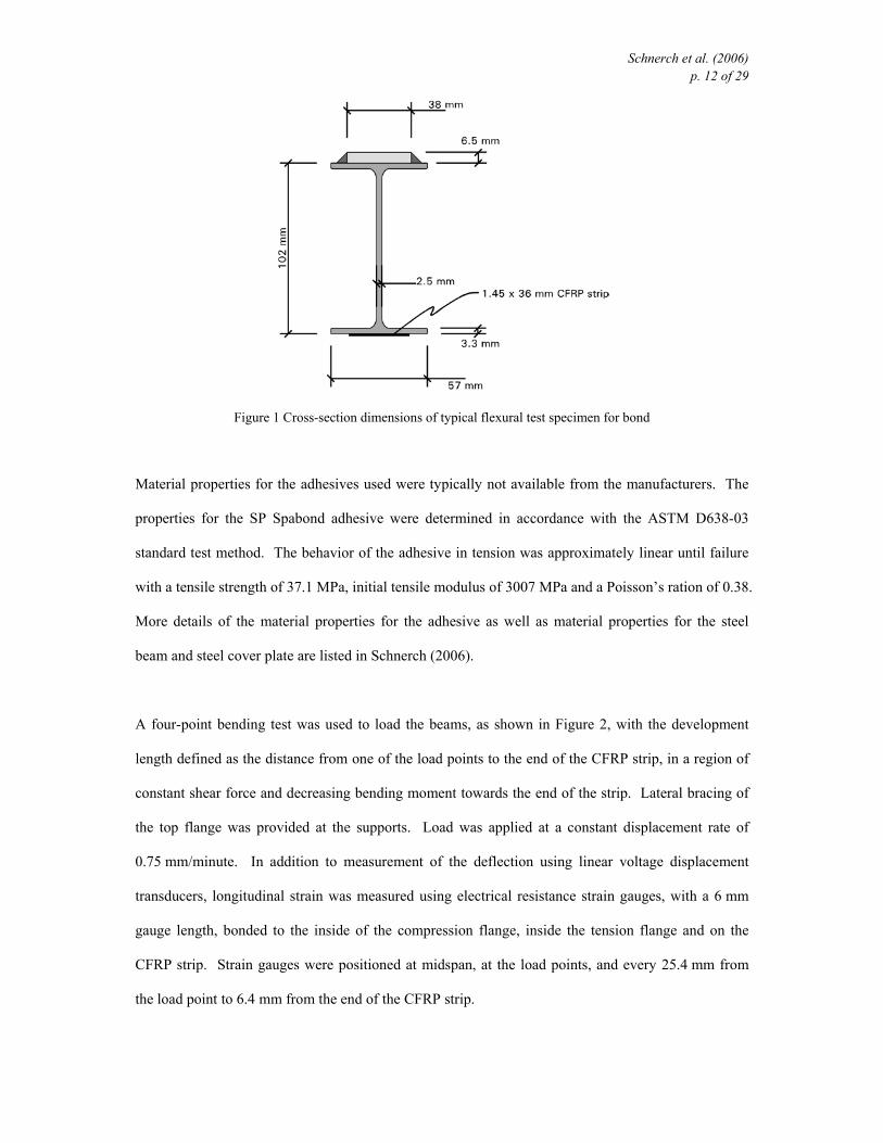
Schnerch et al. (2006) p. 12 of 29
Figure 1 Cross-section dimensions of typical flexural test specimen for bond
Material properties for the adhesives used were typically not available from the manufacturers. The
properties for the SP Spabond adhesive were determined in accordance with the ASTM D638-03
standard test method. The behavior of the adhesive in tension was approximately linear until failure
with a tensile strength of 37.1 MPa, initial tensile modulus of 3007 MPa and a Poisson’s ration of 0.38.
More details of the material properties for the adhesive as well as material properties for the steel
beam and steel cover plate are listed in Schnerch (2006).
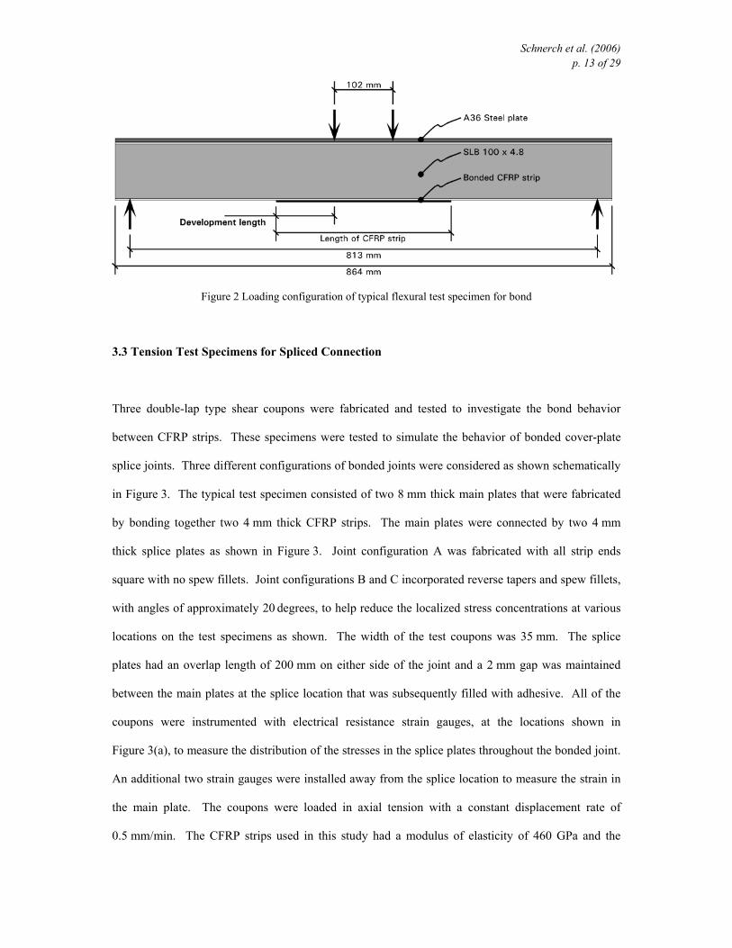
A four-point bending test was used to load the beams, as shown in Figure 2, with the development
length defined as the distance from one of the load points to the end of the CFRP strip, in a region of
constant shear force and decreasing bending moment towards the end of the strip. Lateral bracing of
the top flange was provided at the supports. Load was applied at a constant displacement rate of
0.75 mm/minute. In addition to measurement of the deflection using linear voltage displacement
transducers, longitudinal strain was measured using electrical resistance strain gauges, with a 6 mm
gauge length, bonded to the inside of the compression flange, inside the tension flange and on the
CFRP strip. Strain gauges were positioned at midspan, at the load points, and every 25.4 mm from
the load point to 6.4 mm from the end of the CFRP strip.
Schnerch et al. (2006) p. 13 of 29
Figure 2 Loading configuration of typical flexural test specimen for bond
3.3 Tension Test Specimens for Spliced Connection
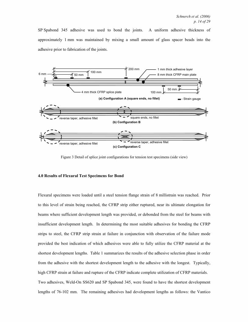
Three double-lap type shear coupons were fabricated and tested to investigate the bond behavior
between CFRP strips. These specimens were tested to simulate the behavior of bonded cover-plate
splice joints. Three different configurations of bonded joints were considered as shown schematically
in Figure 3. The typical test specimen consisted of two 8 mm thick main plates that were fabricated
by bonding together two 4 mm thick CFRP strips. The main plates were connected by two 4 mm
thick splice plates as shown in Figure 3. Joint configuration A was fabricated with all strip ends
square with no spew fillets. Joint configurations B and C incorporated reverse tapers and spew fillets,
with angles of approximately 20 degrees, to help reduce the localized stress concentrations at various
locations on the test specimens as shown. The width of the test coupons was 35 mm. The splice
plates had an overlap length of 200 mm on either side of the joint and a 2 mm gap was maintained
between the main plates at the splice location that was subsequently filled with adhesive. All of the
coupons were instrumented with electrical resistance strain gauges, at the locations shown in
Figure 3(a), to measure the distribution of the stresses in the splice plates throughout the bonded joint.
An additional two strain gauges were installed away from the splice location to measure the strain in
the main plate. The coupons were loaded in axial tension with a constant displacement rate of
0.5 mm/min. The CFRP strips used in this study had a modulus of elasticity of 460 GPa and the
Schnerch et al. (2006) p. 14 of 29
SP Spabond 345 adhesive was used to bond the joints. A uniform adhesive thickness of
approximately 1 mm was maintained by mixing a small amount of glass spacer beads into the
adhesive prior to fabrication of the joints.
Figure 3 Detail of splice joint configurations for tension test specimens (side view)
4.0 Results of Flexural Test Specimens for Bond
Flexural specimens were loaded until a steel tension flange strain of 8 millistrain was reached. Prior
to this level of strain being reached, the CFRP strip either ruptured, near its ultimate elongation for
beams where sufficient development length was provided, or debonded from the steel for beams with
insufficient development length. In determining the most suitable adhesives for bonding the CFRP
strips to steel, the CFRP strip strain at failure in conjunction with observation of the failure mode
provided the best indication of which adhesives were able to fully utilize the CFRP material at the
shortest development lengths. Table 1 summarizes the results of the adhesive selection phase in order
from the adhesive with the shortest development length to the adhesive with the longest. Typically,
high CFRP strain at failure and rupture of the CFRP indicate complete utilization of CFRP materials.
Two adhesives, Weld-On SS620 and SP Spabond 345, were found to have the shortest development
lengths of 76-102 mm. The remaining adhesives had development lengths as follows: the Vantico
square ends, no fillet reverse taper, adhesive fillet
reverse taper, adhesive fillet reverse taper, adhesive fillet
4 mm thick CFRP splice plate
8 mm thick CFRP main plate
1 mm thick adhesive layer
(a) Configuration A (square ends, no fillet)
(b) Configuration B
(c) Configuration C
200 mm 100 mm
50 mm 6 mm
50 mm 100 mm
- Strain gauge
Schnerch et al. (2006) p. 15 of 29
Araldite 2015 and Jeffco 121 adhesives had a development length of 102-127 mm, Fyfe Tyfo MB had
a development length of 152 mm and Sika Sikadur 30 had a development length of more than 203
mm. In all cases, debonding progressed extremely rapidly starting from one end of the CFRP strip to
the other side of the strip. The failure surface typically was mixed with some adhesive remaining
adhered to the steel and some adhesive adhered to the CFRP strip.
Table 1 CFRP strip strain at rupture/debonding for tested adhesives and development lengths
Adhesive Development Length
203.2 mm 152.4 mm 127 mm 101.6 mm 76.2 mm 50.8 mm
Weld-On SS620 3.077
rupture
2.964
rupture -
3.161
rupture
2.903
rupture
2.589
debond
SP Spabond 345 2.878
rupture
2.943
rupture -
3.111
rupture
2.433
debond
1.833
debond
Vantico Araldite
2015
3.094
rupture
2.980
rupture -
2.820
rupture
2.772
debond -
Jeffco 121 2.981
rupture
3.276
rupture
2.662
rupture
2.438
debond - -
Fyfe Tyfo MB2 3.470
rupture
3.060
debond -
2.096
debond - -
Sika Sikadur 30 2.814
debond - - - - -
* underlined values are the average of two test results
Six of the specimens tested were instrumented with strain gauges positioned along the development
length of the bonded CFRP strip on one side of the beam. These strain measurements were recorded
at discrete locations. The difference in tensile strain between two gauge locations must be balanced
by the shear force acting between the CFRP strip and the steel substrate, as noted by Garden et al.
(1998). The average shear stress could then determined between the two gauge locations as,
Schnerch et al. (2006) p. 16 of 29
12
12
xxtE frpfrpav −
−=
εετ (1)
where ε2 - ε1 is the difference in strain between two adjacent gauges and x2 – x1 is the distance
between the gauges. The longitudinal strain at the tip of the CFRP sheet was taken to be zero in order
to calculate the shear stress between the end of the strip and the location of the first strain gauge. As
shown in Table 2, the specimen using the SP Spabond 345 adhesive had the highest shear stresses of
the tests with one ply of CFRP strips. It is possible that some of the other adhesives could have
developed higher shear stresses, had the CFRP strips not ruptured first.
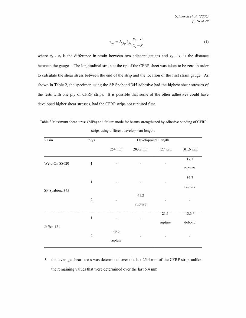
Table 2 Maximum shear stress (MPa) and failure mode for beams strengthened by adhesive bonding of CFRP
strips using different development lengths
Resin plys Development Length
254 mm 203.2 mm 127 mm 101.6 mm
Weld-On SS620 1 - - - 17.7
rupture
1 - - - 36.7
rupture SP Spabond 345
2 - 61.8
rupture - -
1 - - 21.3
rupture
13.3 *
debond Jeffco 121
2 49.9
rupture - - -
* this average shear stress was determined over the last 25.4 mm of the CFRP strip, unlike
the remaining values that were determined over the last 6.4 mm
Schnerch et al. (2006) p. 17 of 29
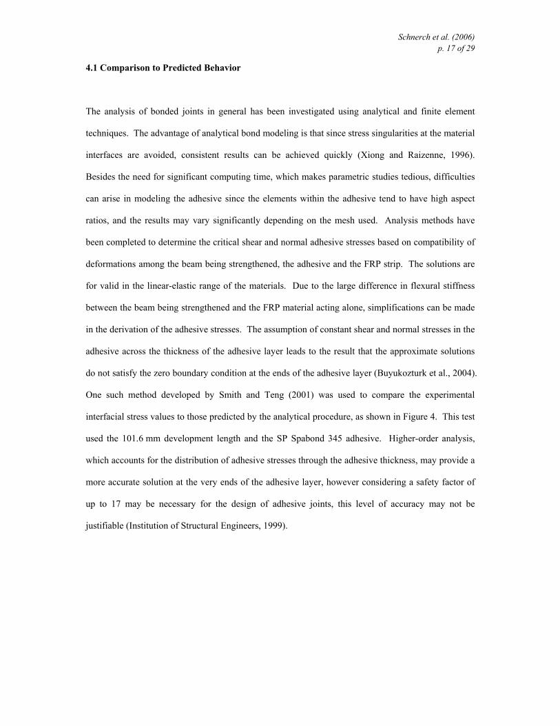
4.1 Comparison to Predicted Behavior
The analysis of bonded joints in general has been investigated using analytical and finite element
techniques. The advantage of analytical bond modeling is that since stress singularities at the material
interfaces are avoided, consistent results can be achieved quickly (Xiong and Raizenne, 1996).
Besides the need for significant computing time, which makes parametric studies tedious, difficulties
can arise in modeling the adhesive since the elements within the adhesive tend to have high aspect
ratios, and the results may vary significantly depending on the mesh used. Analysis methods have
been completed to determine the critical shear and normal adhesive stresses based on compatibility of
deformations among the beam being strengthened, the adhesive and the FRP strip. The solutions are
for valid in the linear-elastic range of the materials. Due to the large difference in flexural stiffness
between the beam being strengthened and the FRP material acting alone, simplifications can be made
in the derivation of the adhesive stresses. The assumption of constant shear and normal stresses in the
adhesive across the thickness of the adhesive layer leads to the result that the approximate solutions
do not satisfy the zero boundary condition at the ends of the adhesive layer (Buyukozturk et al., 2004).
One such method developed by Smith and Teng (2001) was used to compare the experimental
interfacial stress values to those predicted by the analytical procedure, as shown in Figure 4. This test
used the 101.6 mm development length and the SP Spabond 345 adhesive. Higher-order analysis,
which accounts for the distribution of adhesive stresses through the adhesive thickness, may provide a
more accurate solution at the very ends of the adhesive layer, however considering a safety factor of
up to 17 may be necessary for the design of adhesive joints, this level of accuracy may not be
justifiable (Institution of Structural Engineers, 1999).
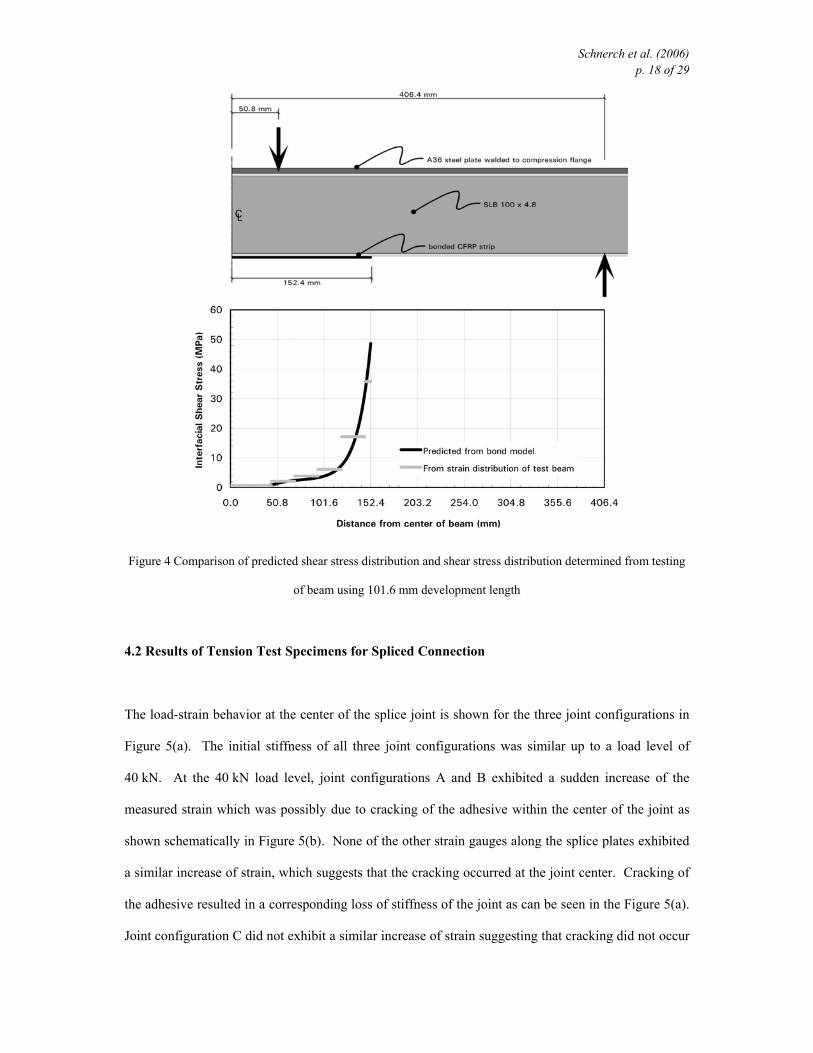
Schnerch et al. (2006) p. 18 of 29
Figure 4 Comparison of predicted shear stress distribution and shear stress distribution determined from testing
of beam using 101.6 mm development length
4.2 Results of Tension Test Specimens for Spliced Connection
The load-strain behavior at the center of the splice joint is shown for the three joint configurations in
Figure 5(a). The initial stiffness of all three joint configurations was similar up to a load level of
40 kN. At the 40 kN load level, joint configurations A and B exhibited a sudden increase of the
measured strain which was possibly due to cracking of the adhesive within the center of the joint as
shown schematically in Figure 5(b). None of the other strain gauges along the splice plates exhibited
a similar increase of strain, which suggests that the cracking occurred at the joint center. Cracking of
the adhesive resulted in a corresponding loss of stiffness of the joint as can be seen in the Figure 5(a).
Joint configuration C did not exhibit a similar increase of strain suggesting that cracking did not occur
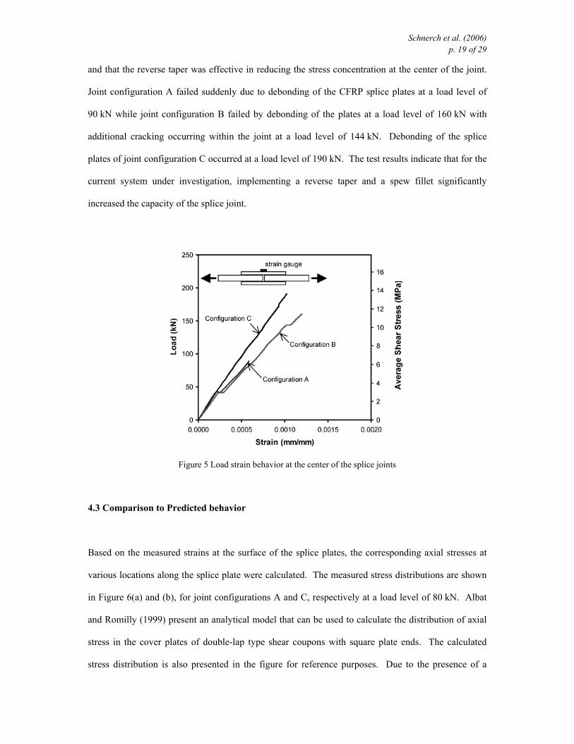
Schnerch et al. (2006) p. 19 of 29
and that the reverse taper was effective in reducing the stress concentration at the center of the joint.
Joint configuration A failed suddenly due to debonding of the CFRP splice plates at a load level of
90 kN while joint configuration B failed by debonding of the plates at a load level of 160 kN with
additional cracking occurring within the joint at a load level of 144 kN. Debonding of the splice
plates of joint configuration C occurred at a load level of 190 kN. The test results indicate that for the
current system under investigation, implementing a reverse taper and a spew fillet significantly
increased the capacity of the splice joint.
Figure 5 Load strain behavior at the center of the splice joints
4.3 Comparison to Predicted behavior
Based on the measured strains at the surface of the splice plates, the corresponding axial stresses at
various locations along the splice plate were calculated. The measured stress distributions are shown
in Figure 6(a) and (b), for joint configurations A and C, respectively at a load level of 80 kN. Albat
and Romilly (1999) present an analytical model that can be used to calculate the distribution of axial
stress in the cover plates of double-lap type shear coupons with square plate ends. The calculated
stress distribution is also presented in the figure for reference purposes. Due to the presence of a
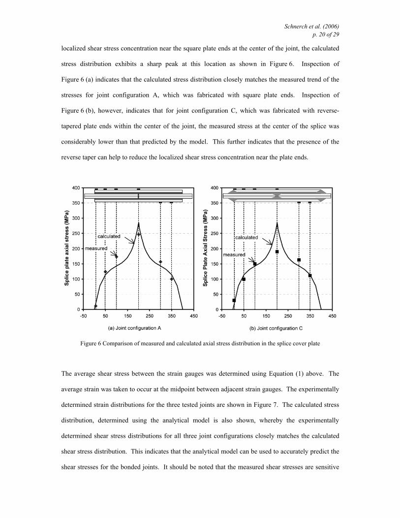
Schnerch et al. (2006) p. 20 of 29
localized shear stress concentration near the square plate ends at the center of the joint, the calculated
stress distribution exhibits a sharp peak at this location as shown in Figure 6. Inspection of
Figure 6 (a) indicates that the calculated stress distribution closely matches the measured trend of the
stresses for joint configuration A, which was fabricated with square plate ends. Inspection of
Figure 6 (b), however, indicates that for joint configuration C, which was fabricated with reverse-
tapered plate ends within the center of the joint, the measured stress at the center of the splice was
considerably lower than that predicted by the model. This further indicates that the presence of the
reverse taper can help to reduce the localized shear stress concentration near the plate ends.
Figure 6 Comparison of measured and calculated axial stress distribution in the splice cover plate
The average shear stress between the strain gauges was determined using Equation (1) above. The
average strain was taken to occur at the midpoint between adjacent strain gauges. The experimentally
determined strain distributions for the three tested joints are shown in Figure 7. The calculated stress
distribution, determined using the analytical model is also shown, whereby the experimentally
determined shear stress distributions for all three joint configurations closely matches the calculated
shear stress distribution. This indicates that the analytical model can be used to accurately predict the
shear stresses for the bonded joints. It should be noted that the measured shear stresses are sensitive
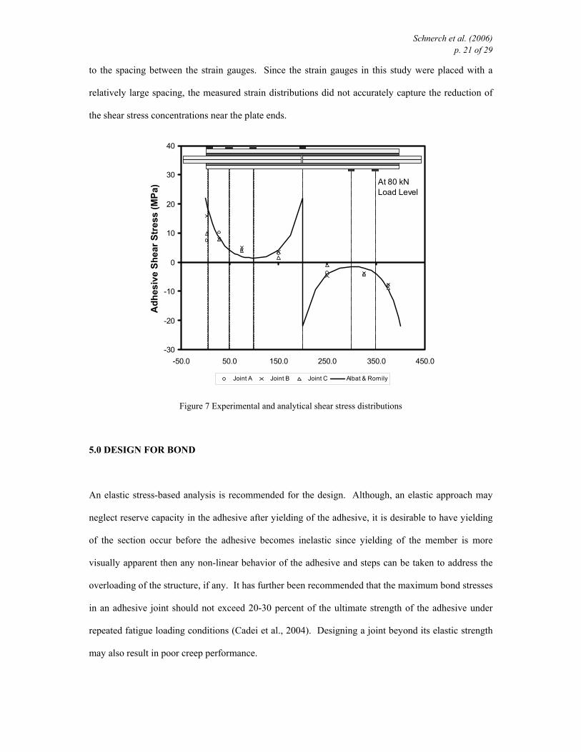
Schnerch et al. (2006) p. 21 of 29
to the spacing between the strain gauges. Since the strain gauges in this study were placed with a
relatively large spacing, the measured strain distributions did not accurately capture the reduction of
the shear stress concentrations near the plate ends.
-30
-20
-10
0
10
20
30
40
-50.0 50.0 150.0 250.0 350.0 450.0
Adh
esiv
e Sh
ear S
tres
s (M
Pa)
Joint A Joint B Joint C Albat & Romily
At 80 kN Load Level
Figure 7 Experimental and analytical shear stress distributions
5.0 DESIGN FOR BOND
An elastic stress-based analysis is recommended for the design. Although, an elastic approach may
neglect reserve capacity in the adhesive after yielding of the adhesive, it is desirable to have yielding
of the section occur before the adhesive becomes inelastic since yielding of the member is more
visually apparent then any non-linear behavior of the adhesive and steps can be taken to address the
overloading of the structure, if any. It has further been recommended that the maximum bond stresses
in an adhesive joint should not exceed 20-30 percent of the ultimate strength of the adhesive under
repeated fatigue loading conditions (Cadei et al., 2004). Designing a joint beyond its elastic strength
may also result in poor creep performance.
Schnerch et al. (2006) p. 22 of 29
An analytical procedure was developed for determining the bond stresses. This procedure allows the
analysis of beams with bonded FRP strips to the tension side of the beam. The analysis includes the
effect of the applied loading, the thermal effects resulting from differing coefficients of thermal
expansion, as well as any prestressing applied to the FRP strip before bonding. Thermal effects
should be considered for any structure that is subjected to thermal changes. More details regarding
the analysis, in addition to techniques to reduce the stresses at the ends of the CFRP strips may be
found in Schnerch (2005).
As indicated by Cadei et al. (2004), the strength of the bond must be determined empirically since this
strength depends not only upon the properties of the substrates and adhesives, but also upon the
degree of surface preparation that is expected. The characteristic strength of an adhesive system can
be established using small-scale single or double lap shear coupon tests. The test coupons should be
prepared using the same materials, surface preparation techniques and application techniques as will
be used for the strengthening project to ensure that the coupon test results are representative of the
expected behavior. The maximum shear stress, τ, and normal stress, σ, can be determined from these
preliminary tests using well established bond models such as those outlined for the case of double-lap
shear specimens (Hart-Smith, 1980). Typically, the maximum shear and normal stresses are
approximately coincident along the length of the adhesive joint. These stresses can then be used to
determine the maximum principal stress, of the adhesive or interface. A design value can then be
determined using an appropriate factor of safety considering the sudden debonding failure mode that
does not give any warning prior to failure.
6.0 CONCLUSIONS
Surface preparation and detailing are essential to ensure satisfactory performance of bonded joints
between steel and FRP materials, which are capable of sustaining the high interfacial stresses
necessary to realize the full strength of these materials. The primary challenge towards the successful
implementation of FRP materials for steel strengthening is the performance of the bond. It is not only

Schnerch et al. (2006) p. 23 of 29
necessary to consider the short term bond performance, but new research should attempt to correlate
the performance of accelerated tests to long-term field performance.
Small-scale flexural tests were conducted to investigate adhesive bond performance. Considerable
variation in the development length and maximum CFRP strain at failure was found among the
adhesives studied. Several of the adhesives were able to achieve rupture of the CFRP strip at
relatively short development lengths. The current study indicates that the development length is
proportional to the number of plys of CFRP strips. Existing analytical techniques are the most
suitable tools that are currently available to designers in describing the bond behavior of steel to
CFRP bonds. These models predict a shear stress concentration at the end of the CFRP, which was
confirmed in the current experimental program. The preliminary experimental results also confirm
the findings of previous finite element studies that the stress concentration at the end the end of the
strip can be significantly reduced by implementing a reverse taper and spew fillet. Adhesive selection
and careful detailing are critical to the satisfactory performance of steel members strengthened with
externally bonded CFRP strips.
7.0 ACKNOWLEDGEMENTS
The authors would like to acknowledge the financial support provided by the National Science
Foundation Industry/University Cooperative Research Center and Mitsubishi Chemical America, Inc..
8.0 REFERENCES
Albat, A.M. and Romilly, D.P. (1999). “A direct linear-elastic analysis of double symmetric bonded
joints and reinforcements,” Composites Science and Technology, v. 59, pp. 1127-1137
Allan, R.C., J. Bird and J.D. Clarke (1988). “Use of adhesives in repair of cracks in ship structures,”
Materials Science and Technology, v. 4, October, pp. 853-859.
Schnerch et al. (2006) p. 24 of 29
Allen, K.W., S.Y.T. Chan and K.B. Armstrong (1982). “Cold-setting adhesives for repair purposes
using various surface preparation methods,” International Journal of Adhesion and Adhesives, v.
2, n. 4, October, pp. 239-247.
Belingardi, G., Goglio, L. and Tarditi, A. (2002). “Investigating the effect of spew and chamfer size
on the stresses in metal/plastics adhesive joints,” International Journal of Adhesion and Adhesives,
v 22, pp. 273-282.
Brown, A.R.G (1974). “Corrosion of CFRP to metal couples in saline environments,” Proceedings of
the 2nd International Conference on Carbon Fibres, London, England, February 18-20, Paper No.
35, pp. 230- 241.
Brown, S.R. and J.J. De Luccia (1977). “Corrosion characteristics of naval aircraft metals and alloys
in contact with graphite-epoxy composites,” Proceedings of the Environmental Degradation of
Engineering Materials Conference, Virginia Polytechnic Institute and State University,
Blacksburg, Virginia, October 10-12, pp. 277-288.
Buyukozturk, Oral, Oguz Gunes, and Erdem Karaca (2004). “Progress on understanding debonding
problems in reinforced concrete and steel members strengthened using FRP composites,”
Construction and Building Materials, v. 18, n. 1, February, pp 9-19.
Cadei, J.M.C., T.J. Stratford, L.C. Hollaway, and W.G. Duckett. (2004). Strengthening Metallic
Structures Using Externally Bonded Fibre-Reinforced Polymers. Publication C595, Construction
Industry Research and Information Association (CIRIA), London, UK, 234 p.
Choqueuse, D., P. Davies, F. Mazeas, R. Baizeau (1997). “Aging of composites in water:
Comparison of five materials in terms of absorption kinetics and evolution of mechanical
properties,” High Temperature and Environmental Effects on Polymeric Composites: 2nd Volume,
ASTM Special Technical Publication 1302, Thomas S. Gates and Abdul-Hamid Zureick, eds.,
American Society for Testing and Materials, pp. 73-96.
Dawood, M. (2005). Fundamental Behavior of Steel-Concrete Composite Beams Strengthened with
High Modulus Carbon Fiber Reinforced Polymer Materials. Master’s Thesis, North Carolina
State University, 213 p.
Schnerch et al. (2006) p. 25 of 29
El Damatty, A, M. Abushagur, and M.A. Youssef (2003). “Experimental and analytical investigation
of steel beams rehabilitated using GFRP Sheets,” Steel and Composite Structures, v. 3, n. 6,
December, pp. 421-438.
Evans, Ulick R. and Vera E. Rance (1958). Corrosion and its Prevention at Bimetallic Contacts. Her
Majesty’s Stationery Office, London, England.
Francis, R (2000). Bimetallic Corrosion: Guides to Good Practice in Corrosion Control. National
Physical Laboratory, Teddington, Middlesex, 15 p.
Frieze P.A. and F.J. Barnes (1996). “Composite materials for offshore application – New data and
practice,” Proceedings of the 28th Annual Offshore Technology Conference, v. 3, Construction
and Installation, Houston, Texas, May 6-9, pp. 247-253.
Garden, H.N., R.J. Quantrill, L.C. Hollaway, A.M. Thorne, and G.A.R. Parke (1998). “An
experimental study on the anchorage length of carbon fibre composite plates used to strengthen
reinforced concrete beams,” Construction and Building Materials, v. 42, n. 2, June, pp. 175-188.
Gettings, M. and A.J. Kinloch (1977). “Surface analysis of polysiloxane/metal oxide interfaces,”
Journal of Materials Science, v. 12, n. 12, December, pp. 2511-2518
Harris, A.F. and A. Beevers (1999). “The effects of grit blasting on surface properties for adhesion,”
International Journal of Adhesion and Adhesives, v. 19, n. 6, December, pp. 445-452.
Hart-Smith, L.J. (1980). “Further developments in the design and analysis of adhesive-bonded
structural joints,” ASTM Special Technical Publication 749, Joining of Composite Materials: A
Symposium, K.T. Kedward, Ed., April 16, pp. 3-31.
Hashim, S.A. (1999). “Adhesive bonding of thick steel adherends for marine structures,” Marine
Structures, v. 12, n. 6, pp. 405-423.
Hildebrand, M (1994). “Non-linear analysis and optimization of adhesively bonded single lap joints
between fibre-reinforced plastics and metals,” International Journal of Adhesion and Adhesives,
v. 14, n. 4, October, pp. 261-267.
Hollaway, L.C. and J. Cadei (2002). “Progress in the technique of upgrading metallic structures with
advanced polymer composites,” Progress in Structural Engineering Materials, v. 4, n. 2, April-
June, pp, 131-148.
Schnerch et al. (2006) p. 26 of 29
Hutchinson, A.R. (1987). “Surface pretreatment – the key to durability,” Proceedings of the
International Conference on Structural Faults & Repair, University of London, July 1987, pp.
235-244.
Institution of Structural Engineers. A Guide to the Structural Use of Adhesives. The Institution of
Structural Engineers, London, UK, 1999, 51 p.
Karbhari, V.M. and S.B. Shulley (1995). “Use of composites for rehabilitation of steel structures -
determination of bond durability,” Journal of Materials in Civil Engineering, v. 7, n. 4, November,
pp 239-245
Lenwari, A., Thepchatri, T and Albrecht, P. (2006). “Debonding Strength of Steel Beams
Strengthened with CFRP Plates,” ASCE Journal of Composites for Construction, v. 10, no. 1,
January/February, pp. 69-78.
Mays, G.C. and A.R. Hutchinson (1992). Adhesives in Civil Engineering. Cambridge University
Press, New York, New York, 333 p.
McKnight, Steven H., Pierre E. Bourban, John W. Gillespie, Jr., and Vistap M. Karbhari (1994).
“Surface preparation of steel for surface bonding applications,” Infrastructure: New Materials
and Methods of Repair, Proceedings of the 3rd Materials Engineering Conference, ASCE, Kim D.
Basham, Ed., Nov 13-16, San Diego, California, pp, 1148-1155.
Miller, Trent C., Michael J. Chajes, Dennis R. Mertz, and Jason N. Hastings (2001). “Strengthening
of a steel bridge girder using CFRP plates,” ASCE Journal of Bridge Engineering, v. 6, no. 6,
November-December, pp. 514-522.
Miriyala, S.K., W.C. Tucker, T.J. Rockett, and R. Brown (1992). “Degradation of carbon reinforced
polymer composites under galvanic coupling conditions,” Proceedings of the 33rd
AIAA/ASME/ASCE/AHS/ASC Structures, Structural Dynamics, and Materials Conference, Dallas,
Texas, April 13-15, pp. 3036-3045.
Nozaka, Katsuyoshi, Carol K. Shield, and Jerome F. Hajjar (2005). “Effective bond length of carbon-
fiber-reinforced polymer strips bonded to fatigued steel bridge I-girders,” Journal of Bridge
Engineering, ASCE, v. 10, n. 2, March, pp. 195-205.
Schnerch et al. (2006) p. 27 of 29
Ong, C.L. and S.B. Shen (1992). “The reinforcing effect of composite patch repairs on metallic
aircraft structures,” International Journal of Adhesion and Adhesives, v. 12, n. 1, January, pp. 19-
26.
Parker, B.M. (1994). “Adhesive bonding of fibre-reinforced composites,” International Journal of
Adhesion and Adhesives, v. 14, n. 2, April, pp. 137-143.
Photiou, N.K., L.C. Hollaway, and M.K. Chryssanthopoulos. (2004) “An ultra-high modulus
carbon/glass fibre composite system for structural upgrading of steel members,” Proceedings of
the 2nd International Conference on FRP Composites in Civil Engineering – CICE 2004,
Seracino, R., ed., December 8-10, 741-748.
Price, A. and R.J. Moulds (1991). “Repair and strengthening of structures using plate bonding,”
Construction and Building Materials, v. 5, n. 4, December, pp. 189-192.
Schnerch, David A. (2005). Strengthening of Steel Structures with High Modulus Carbon Fiber
Reinforced Polymer (CFRP) Materials. Ph.D. Dissertation, North Carolina State University,
265 p.
Sloan, F.E. and J. B. Talbot (1992). “Corrosion of graphite-fiber-reinforced composites I - galvanic
coupling damage,” Corrosion, v. 48, n. 10, October, pp. 830-838.
Smith, S.T. and J.G. Teng (2001). “Interfacial stresses in plated beams,” Engineering Structures, v.
23, n. 7, July, pp. 857-871.
Stallings, M. and N.M. Porter (2003). “Experimental investigation of lap splices in externally bonded
carbon fiber-reinforced plastic plates,” ACI Structural Journal, v. 100, n. 1 January-February, pp.
3-10.
Sykes, J.M. (1982). “Surface treatments for steel,” Surface Analysis and Pretreatment of Plastics and
Metals, D.M. Brewis, Ed., Applied Science Publishers, Ltd., Essex, England, pp. 153-174.
Tang, Benjamin M. and John M. Hooks (2001). “FRP Composites industry is changing the American
bridge building industry,” Proceedings of the International Conference on FRP Composites in
Civil Engineering, v. 2, J.G. Teng, ed., Hong Kong, December 12-15, pp. 1657-1663.
Schnerch et al. (2006) p. 28 of 29
Tavakkolizadeh, Mohammadreza and Hamid Saadatmanesh (2001). “Galvanic corrosion of carbon
and steel in aggressive environments,” Journal of Composites for Construction, v. 5, n. 3, August,
pp 200-210.
Tucker, Wayne C. and Richard Brown (1989), “Blister formation on graphite/polymer composites
galvanically coupled with steel in seawater,” Journal of Composite Materials, v. 23, n. 4, April,
pp. 389-395.
West, Todd Douglas (2001). Enhancements to the Bond Between Advanced Composite Materials and
Steel for Bridge Rehabilitation. Master’s Thesis, University of Delaware, 207 p.
Wright, P.N.H., Y. Wu and A.G. Gibson (2000). “Fibre reinforced composite-steel connections for
transverse ship bulkheads,” Plastics, Rubber and Composites, v. 29, n. 10, pp. 549-557.
Xiong, Y. and D. Raizenne (1996). “Stress and failure analysis of bonded composite-to-metal joints,”
AGARD specialist meeting on bolted/bonded joints in polymeric composites, AGARD conference
proceedings 590, Florence, Italy, September, pp. 9.1-9.11.
Yang, X. and A. Nanni (2002). “Lap splice length and fatigue performance of fiber-reinforced
polymer laminates,” ACI Materials Journal, v. 99, n. 4, July-August, pp. 386-392.

Schnerch et al. (2006) p. 29 of 29
NOTATION
Efrp = Modulus of elasticity of FRP
tfrp = thickness of FRP strip
τ = shear stress
τav = average shear stress
σ = normal or peel stress